US20040252632A1 - Method and apparatus for multi-user multi-input multi-output transmission - Google Patents
Method and apparatus for multi-user multi-input multi-output transmission Download PDFInfo
- Publication number
- US20040252632A1 US20040252632A1 US10/645,858 US64585803A US2004252632A1 US 20040252632 A1 US20040252632 A1 US 20040252632A1 US 64585803 A US64585803 A US 64585803A US 2004252632 A1 US2004252632 A1 US 2004252632A1
- Authority
- US
- United States
- Prior art keywords
- signals
- data signals
- sub
- determining
- receiving
- Prior art date
- Legal status (The legal status is an assumption and is not a legal conclusion. Google has not performed a legal analysis and makes no representation as to the accuracy of the status listed.)
- Granted
Links
Images


Classifications
-
- H—ELECTRICITY
- H04—ELECTRIC COMMUNICATION TECHNIQUE
- H04B—TRANSMISSION
- H04B7/00—Radio transmission systems, i.e. using radiation field
- H04B7/02—Diversity systems; Multi-antenna system, i.e. transmission or reception using multiple antennas
- H04B7/04—Diversity systems; Multi-antenna system, i.e. transmission or reception using multiple antennas using two or more spaced independent antennas
- H04B7/0413—MIMO systems
- H04B7/0452—Multi-user MIMO systems
-
- H—ELECTRICITY
- H04—ELECTRIC COMMUNICATION TECHNIQUE
- H04B—TRANSMISSION
- H04B17/00—Monitoring; Testing
- H04B17/10—Monitoring; Testing of transmitters
- H04B17/11—Monitoring; Testing of transmitters for calibration
- H04B17/12—Monitoring; Testing of transmitters for calibration of transmit antennas, e.g. of the amplitude or phase
-
- H—ELECTRICITY
- H04—ELECTRIC COMMUNICATION TECHNIQUE
- H04B—TRANSMISSION
- H04B17/00—Monitoring; Testing
- H04B17/20—Monitoring; Testing of receivers
- H04B17/21—Monitoring; Testing of receivers for calibration; for correcting measurements
-
- H—ELECTRICITY
- H04—ELECTRIC COMMUNICATION TECHNIQUE
- H04B—TRANSMISSION
- H04B17/00—Monitoring; Testing
- H04B17/40—Monitoring; Testing of relay systems
- H04B17/401—Monitoring; Testing of relay systems with selective localization
-
- H—ELECTRICITY
- H04—ELECTRIC COMMUNICATION TECHNIQUE
- H04B—TRANSMISSION
- H04B7/00—Radio transmission systems, i.e. using radiation field
- H04B7/02—Diversity systems; Multi-antenna system, i.e. transmission or reception using multiple antennas
- H04B7/04—Diversity systems; Multi-antenna system, i.e. transmission or reception using multiple antennas using two or more spaced independent antennas
- H04B7/0413—MIMO systems
- H04B7/0456—Selection of precoding matrices or codebooks, e.g. using matrices antenna weighting
- H04B7/046—Selection of precoding matrices or codebooks, e.g. using matrices antenna weighting taking physical layer constraints into account
- H04B7/0465—Selection of precoding matrices or codebooks, e.g. using matrices antenna weighting taking physical layer constraints into account taking power constraints at power amplifier or emission constraints, e.g. constant modulus, into account
-
- H—ELECTRICITY
- H04—ELECTRIC COMMUNICATION TECHNIQUE
- H04L—TRANSMISSION OF DIGITAL INFORMATION, e.g. TELEGRAPHIC COMMUNICATION
- H04L1/00—Arrangements for detecting or preventing errors in the information received
- H04L1/02—Arrangements for detecting or preventing errors in the information received by diversity reception
- H04L1/06—Arrangements for detecting or preventing errors in the information received by diversity reception using space diversity
-
- H—ELECTRICITY
- H04—ELECTRIC COMMUNICATION TECHNIQUE
- H04L—TRANSMISSION OF DIGITAL INFORMATION, e.g. TELEGRAPHIC COMMUNICATION
- H04L5/00—Arrangements affording multiple use of the transmission path
- H04L5/0001—Arrangements for dividing the transmission path
- H04L5/0014—Three-dimensional division
- H04L5/0023—Time-frequency-space
-
- H—ELECTRICITY
- H04—ELECTRIC COMMUNICATION TECHNIQUE
- H04B—TRANSMISSION
- H04B17/00—Monitoring; Testing
- H04B17/10—Monitoring; Testing of transmitters
-
- H—ELECTRICITY
- H04—ELECTRIC COMMUNICATION TECHNIQUE
- H04B—TRANSMISSION
- H04B17/00—Monitoring; Testing
- H04B17/20—Monitoring; Testing of receivers
-
- H—ELECTRICITY
- H04—ELECTRIC COMMUNICATION TECHNIQUE
- H04B—TRANSMISSION
- H04B17/00—Monitoring; Testing
- H04B17/30—Monitoring; Testing of propagation channels
- H04B17/309—Measuring or estimating channel quality parameters
- H04B17/364—Delay profiles
-
- H—ELECTRICITY
- H04—ELECTRIC COMMUNICATION TECHNIQUE
- H04B—TRANSMISSION
- H04B7/00—Radio transmission systems, i.e. using radiation field
- H04B7/02—Diversity systems; Multi-antenna system, i.e. transmission or reception using multiple antennas
- H04B7/04—Diversity systems; Multi-antenna system, i.e. transmission or reception using multiple antennas using two or more spaced independent antennas
- H04B7/0413—MIMO systems
- H04B7/0426—Power distribution
- H04B7/0434—Power distribution using multiple eigenmodes
- H04B7/0443—Power distribution using multiple eigenmodes utilizing "waterfilling" technique
-
- H—ELECTRICITY
- H04—ELECTRIC COMMUNICATION TECHNIQUE
- H04B—TRANSMISSION
- H04B7/00—Radio transmission systems, i.e. using radiation field
- H04B7/02—Diversity systems; Multi-antenna system, i.e. transmission or reception using multiple antennas
- H04B7/04—Diversity systems; Multi-antenna system, i.e. transmission or reception using multiple antennas using two or more spaced independent antennas
- H04B7/0413—MIMO systems
- H04B7/0456—Selection of precoding matrices or codebooks, e.g. using matrices antenna weighting
- H04B7/0478—Special codebook structures directed to feedback optimisation
-
- H—ELECTRICITY
- H04—ELECTRIC COMMUNICATION TECHNIQUE
- H04B—TRANSMISSION
- H04B7/00—Radio transmission systems, i.e. using radiation field
- H04B7/02—Diversity systems; Multi-antenna system, i.e. transmission or reception using multiple antennas
- H04B7/04—Diversity systems; Multi-antenna system, i.e. transmission or reception using multiple antennas using two or more spaced independent antennas
- H04B7/06—Diversity systems; Multi-antenna system, i.e. transmission or reception using multiple antennas using two or more spaced independent antennas at the transmitting station
- H04B7/0613—Diversity systems; Multi-antenna system, i.e. transmission or reception using multiple antennas using two or more spaced independent antennas at the transmitting station using simultaneous transmission
-
- H—ELECTRICITY
- H04—ELECTRIC COMMUNICATION TECHNIQUE
- H04B—TRANSMISSION
- H04B7/00—Radio transmission systems, i.e. using radiation field
- H04B7/02—Diversity systems; Multi-antenna system, i.e. transmission or reception using multiple antennas
- H04B7/04—Diversity systems; Multi-antenna system, i.e. transmission or reception using multiple antennas using two or more spaced independent antennas
- H04B7/08—Diversity systems; Multi-antenna system, i.e. transmission or reception using multiple antennas using two or more spaced independent antennas at the receiving station
- H04B7/0837—Diversity systems; Multi-antenna system, i.e. transmission or reception using multiple antennas using two or more spaced independent antennas at the receiving station using pre-detection combining
-
- H—ELECTRICITY
- H04—ELECTRIC COMMUNICATION TECHNIQUE
- H04L—TRANSMISSION OF DIGITAL INFORMATION, e.g. TELEGRAPHIC COMMUNICATION
- H04L1/00—Arrangements for detecting or preventing errors in the information received
- H04L1/0001—Systems modifying transmission characteristics according to link quality, e.g. power backoff
- H04L1/0002—Systems modifying transmission characteristics according to link quality, e.g. power backoff by adapting the transmission rate
- H04L1/0003—Systems modifying transmission characteristics according to link quality, e.g. power backoff by adapting the transmission rate by switching between different modulation schemes
-
- H—ELECTRICITY
- H04—ELECTRIC COMMUNICATION TECHNIQUE
- H04L—TRANSMISSION OF DIGITAL INFORMATION, e.g. TELEGRAPHIC COMMUNICATION
- H04L1/00—Arrangements for detecting or preventing errors in the information received
- H04L1/0001—Systems modifying transmission characteristics according to link quality, e.g. power backoff
- H04L1/0009—Systems modifying transmission characteristics according to link quality, e.g. power backoff by adapting the channel coding
-
- H—ELECTRICITY
- H04—ELECTRIC COMMUNICATION TECHNIQUE
- H04L—TRANSMISSION OF DIGITAL INFORMATION, e.g. TELEGRAPHIC COMMUNICATION
- H04L25/00—Baseband systems
- H04L25/02—Details ; arrangements for supplying electrical power along data transmission lines
- H04L25/0202—Channel estimation
- H04L25/0204—Channel estimation of multiple channels
-
- H—ELECTRICITY
- H04—ELECTRIC COMMUNICATION TECHNIQUE
- H04L—TRANSMISSION OF DIGITAL INFORMATION, e.g. TELEGRAPHIC COMMUNICATION
- H04L25/00—Baseband systems
- H04L25/02—Details ; arrangements for supplying electrical power along data transmission lines
- H04L25/0202—Channel estimation
- H04L25/022—Channel estimation of frequency response
-
- H—ELECTRICITY
- H04—ELECTRIC COMMUNICATION TECHNIQUE
- H04L—TRANSMISSION OF DIGITAL INFORMATION, e.g. TELEGRAPHIC COMMUNICATION
- H04L27/00—Modulated-carrier systems
- H04L27/26—Systems using multi-frequency codes
- H04L27/2601—Multicarrier modulation systems
Definitions
- the present invention relates to a method for multi-user MIMO transmission, more in particular, a method for transmission between a base station and U (>1) user terminals, said base station and user terminals each equipped with more than one antenna, preferably in conjunction with considering the optimizing of joint transmit and receive filters, for instance in a MMSE context. Further disclosed are base station and user terminal devices suited for execution of said method.
- Multi-input multi-output (MIMO) wireless communications have attracted a lot of interest in the recent years as they offer a multiplicity of spatial channels for the radio links, hence provide a significant capacity or diversity increase compared to conventional single antenna communications.
- Multi-Input Multi-Output (MIMO) wireless channels have significantly higher capacities than conventional Single-Input Single-Output (SISO) channels. These capacities are related to the multiple parallel spatial subchannels that are opened through the use of multiple antennas at both the transmitter and the receiver.
- Spatial Multiplexing (SM) is a technique that transmits parallel independent data-streams on these available spatial subchannels in an attempt to approach the MIMO capacities.
- SDMA Spatial-Division Multiple Access
- a sub-optimal approach consists of using a fixed number of data streams and identical modulation and coding as in a single-user joint transmit-receive (TX-RX) MMSE optimization [H. Sampath and A. Paulraj, “Joint TX & RX Optimization for High Data Rate Wireless Communication Using Multiple Antennas”, Asilomar conf. On signals, systems and computers , pp. 215-219, Asilomar, Calif., November 1999].
- This latter solution is more convenient but is not directly applicable to SDMA MIMO communications where a multi-antenna base station communicates at the same time with several multi-antenna terminals.
- the joint TX-RX optimization requires channel knowledge at both sides, which is rather unfeasible at the terminal side (the terminal only knows its part of the multi-user wireless channel).
- multi-user interference results in a performance limitation. Further, the joint determination of optimal filters for both the base station and the user terminals in the case of a multi-user context is very complex.
- Embodiments of the present invention provide a solution for the problem of multi-user interference in a multi-user MIMO transmission scheme, which results in a reasonably complex filter determination in the case of joint optimal filter determination, although the invention is not limited thereto.
- the invention includes a method of multi-user MIMO transmission of data signals from at least one transmitting terminal with a spatial diversity capability to at least two receiving user terminals, each provided with spatial diversity receiving capability, comprising: dividing said data signals into a plurality of streams of (sub-user) data sub-signals; determining combined data signals in said transmitting terminal, said combined data signals being transformed versions of said streams of data sub-signals, such that at least one of said spatial diversity devices of said receiving user terminals only receives data sub-signals being specific for the corresponding receiving user terminal; inverse subband processing said combined data signals; transmitting with said spatial diversity device said inverse subband processed combined data signals; receiving on at least one of said spatial diversity receiving device of at least one of said receiving terminals received data signals, being at least a function of said inverse subband processed combined data signals; determining on at least one of said receiving terminals estimates of said data sub-signals from said received data signals; and collecting said estimates of said data sub-signals into estimates of said data signals.
- the transmission of the inverse subband processed combined data signals is performed in a substantially simultaneous way.
- the spectra of the inverse subband processed combined data signals are at least partly overlapping.
- the step of determining combined data signals in the transmitting terminal is carried out on a subband by subband basis. In other embodiments, the step of determining the estimates of said data sub-signals in the receiving terminals comprises subband processing.
- the determining combined data signals in the transmitting terminal may additionally comprise: determining intermediate combined data signals by subband processing of the data signals; and determining the combined data signals from the intermediate combined data signals.
- the subband processing includes orthogonal frequency division demultiplexing and the inverse subband processing includes orthogonal frequency division multiplexing.
- the method includes subbands that are involved in inverse subband processing being grouped into sets, whereby at least one set includes at least two subbands and the step of determining combined data signals in the transmitting terminal comprises: determining relations between the data signals and the combined data signals on a set-by-set basis; and exploiting the relations between the data signals and the combined data signals for determining the data signals.
- a guard interval may be introduced in the inverse subband processed combined data signals.
- the determining combined data signals may further comprise transmitter filtering.
- the determining estimates of the sub-signals comprises receiver filtering, said transmitter filtering and said receiver filtering being determined on a user-by-user basis.
- the number of streams of data sub-signals is variable. In other embodiments, the number of streams is selected in order to minimize the error between the estimates of the data sub-signals and the data sub-signals themselves. Alternatively, the number of streams may be selected in order to minimize the system bit error rate.
- Another aspect includes a method of transmitting data signals from at least two transmitting terminals each provided with spatial diversity transmitting device to at least one receiving terminal with a spatial diversity receiving device comprising: dividing said data signals into a plurality of streams of (sub-user) data sub-signals; transforming versions of said streams of said data sub-signals into transformed data signals; transmitting from said transmitting terminals said transformed data signals; receiving on said spatial diversity receiving device received data signals being at least function of at least two of said transformed data signals; subband processing of at least two of said received data signals in said receiving terminal; applying a linear filtering on said subband processed received data signals, said linear filtering and said transforming being selected such that the filtered subband processed received data signals are specific for one of said transmitting terminals; determining estimates of said data sub-signals from said filtered subband processed received data signals in said receiving terminal; and collecting said estimates of said data sub-signals into estimates of said data signals.
- the transmission is substantially simultaneous and the spectra of the transformed data signals are at least partly overlapping.
- the transformation of the data sub-signals to transformed data sub-signals may comprise inverse subband processing.
- the determining estimates of the data sub-signals from subband processed received data signals in the receiving terminal comprises: determining intermediate estimates of the data sub-signals from the subband processed received data signals in the receiving terminal; and obtaining the estimates of the data sub-signals by inverse subband processing the intermediate estimates.
- Another aspect includes an apparatus for transmitting inverse subband processed combined data signals to at least one receiving user terminal with spatial diversity device comprising at least: at least one spatial diversity transmitter; circuitry configured to divide data signals into streams of data sub-signals; circuitry configured to combine data signals, such that at least one of said spatial diversity device of said receiving user terminals only receives data sub-signals being specific for the corresponding receiving user terminal; circuitry being adapted for inverse subband processing combined data signals; and circuitry being adapted for transmitting inverse subband processed combined data signals with said spatial diversity device.
- the circuitry is configured to combine data signals and may comprise a plurality of circuits, each configured to combine data signals based at least on part of the subbands of the data sub-signals.
- the spatial diversity transmitter comprises at least two transmitters and the circuitry configured to transmit inverse subband processed combined data signals comprises a plurality of circuits configured to transmit the inverse subband processed combined data signals with one of the transmitters of the spatial diversity device.
- Yet another aspect includes an apparatus for transmitting data signals to at least one receiving terminal with the spatial diversity device, comprising at least: at least one spatial diversity transmitter; circuitry configured to divide data signals into streams of data sub-signals; circuitry configured to transform versions of the data sub-signals; and circuitry configured to transmit with the spatial diversity device the transformed versions of the data sub-signals, such that at least one of the spatial diversity devices of the receiving terminal only receives specific received data sub-signals.
- a further aspect includes a method to calibrate a transceiver for wireless communication comprising at least one transmitter/receiver pair connected to an antenna branch, such that front-end mismatches in the transmitter/receiver pair can be compensated, comprising: providing a splitter, a directional coupler, a transmit/receive/calibration switch, a calibration noise source and a power splitter; matching the power splitter outputs between all branches of the transceiver, matching the directional couplers and matching the transmit/receive/calibration switches between all antenna branches of the transceiver; switching on the calibration connection of the transmit/receive/calibration switch; in each of the antenna branches, generating a known signal and calculating an averaged frequency response of the cascade of the transmitter and the receiver of the transmitter/receiver pair; connecting the transmit/receive/calibration switch so as to isolate the receiver from both the transmitter and the antenna; switching on the calibration noise source; calculating an averaged frequency response of all receiver
- the transceiver is a base station transceiver.
- the pre-compensating may be performed digitally.
- FIG. 1 illustrates a downlink communication set-up.
- FIG. 2 illustrates an uplink communication set-up.
- FIG. 3 illustrates the multi-user (U>1), MIMO (A>1, B u ⁇ 1), multi-stream (C u ⁇ 1) context of the systems and methods.
- FIG. 4 illustrates the involved matrices.
- FIGS. 5 and 6 illustrate simulations results for the block diagionalization approach used in the context of joined transmit and receive filter optimization.
- FIG. 7 illustrates the matrix dimension for 8 antennas at the base station.
- FIG. 8 illustrates a Spatial Multiplexing MIMO System.
- FIG. 9 illustrates the existence (a) and distribution (b) of the optimal number of streams p opt for a (6,6) MIMO system.
- FIG. 10 illustrates p opt 's distribution for different reference rates R.
- FIG. 11 illustrates the MSE p versus p for different SNR levels.
- FIG. 12 illustrates a comparison between the exact MSE p and the simplified one.
- FIG. 13 illustrates a comparison between the BER performance of the spatially optimized and conventional Tx/Rx MMSE.
- FIG. 14 illustrates a comparison of the spatially optimized joint Tx/Rx MMSE to the optimal joint Tx/Rx MMSE and spatial adaptive loading for different reference rates R.
- FIG. 15 illustrates a block diagram of a multi-antenna base station with calibration loop.
- FIG. 16 illustrates the BER degradation with and without calibration.
- FIG. 17 illustrates a second calibration method.
- Embodiments of the systems and methods involve (wireless) communication between terminals.
- One can logically group the terminals on each side of the communication and refer to them as peers.
- the peer(s) on one side of the communication can embody at least two user terminals, whereas on the other side the peer(s) can embody at least one base station.
- the systems and methods can involve multi-user communications.
- the peers can transmit and/or receive information.
- the peers can communicate in a half-duplex fashion, which refers to either transmitting or receiving at one instance of time, or in a full duplex fashion, which refers to substantially simultaneously transmitting and receiving.
- Certain embodiments include MIMO wireless communication channels, as they have significantly higher capacities than conventional SISO channels.
- MIMO approaches may be used, depending on whether channel knowledge is available at either the transmit or receive side, as discussed below.
- FIG. 1 illustrates a downlink communication set-up
- FIG. 2 illustrates an uplink communication set-up
- SDMA Space Division Multiple Access
- communication peers 30 , 230 include terminal(s) 40 , 240 disposing of transmitting and/or receiving devices 80 , 220 that are able to provide different spatial samples of the transmitted and/or received signals. These transmission and/or receiving devices are called spatial diversity devices.
- a peer at the base station side is called a processing peer 30 , 230 .
- a processing peer communicates with at least two terminals at an opposite peer 10 , 340 , which can operate at least partially simultaneously and the communicated signals' spectra can at least partially overlap.
- the opposite peer(s) includes at least two user terminals 20 , 330 (labeled in FIG. 1 as User Terminal 1 and User Terminal 2 ) using the same frequencies at the same time, and are referred to as the composite peer(s) 10 , 340 .
- the systems and methods involve (wireless) communication between terminals whereby at least the processing peer(s) 30 , 230 disposes of subband processing capabilities.
- the communication between a composite peer and a processing peer can include downlink (FIG. 1) and uplink (FIG. 2) transmissions.
- Uplink transmission refers to a transmission whereby the composite peer transmits data signals and the processing peer receives data signals.
- Downlink transmission refers to a transmission whereby the processing peer transmits data signals and the composite peer receives data signals.
- the uplink and downlink transmissions can be, for example, simultaneous (full duplex) with respect to the channel (for example, using different frequency bands), or they can operate in a time-duplex fashion (half duplex)(for example using the same frequency band), or any other configuration.
- a (linear) pre-filter can be used at the transmit side, to achieve a block diagonalization of the channel.
- At the receiver side (linear) post-filtering can be applied.
- (Wireless) transmission of data or a digital signal from a transmitting to a receiving circuit includes digital to analog conversion in the transmission circuit and analog to digital conversion in the receiving circuit.
- the apparatus in the communication set-up can have transmission and receiving devices, also referred to as front-end, incorporating these analog-to-digital and digital-to-analog conversions, including amplification or signal level gain control and realizing the conversion of the RF signal to the required baseband signal and vice versa.
- a front-end can comprise amplifiers, filters and mixers (down converters).
- Communication of a data or a digital signal is thus symbolized as the transmission and reception of a sequence of (discrete) samples.
- the information contained in the data signals can be fed to one or more carriers or pulse-trains by mapping said data signals to symbols which consequently modulate the phase and/or amplitude of the carrier(s) or pulse-trains (e.g., using quadrature amplitude modulation (QAM) or quadrature phase shift keying (QPSK) modulation).
- QAM quadrature amplitude modulation
- QPSK quadrature phase shift keying
- the symbols belong to a finite set, which is called the transmitting alphabet.
- the signals resulting after performing modulation and/or front-end operations on the data signals are called transformed data signals, to be transmitted further.
- the information contained in the received signals is retrieved by transformation and estimation processes.
- these transformation and estimation processes can include demodulation, subband processing, decoding and equalization. In other embodiments, these transformation and estimation processes do not include demodulation, subband processing, decoding and equalization.
- received data signals are obtained, including symbols belonging to a finite set, which is called the receiving alphabet.
- the receiving alphabet is preferably equal to the transmitting alphabet.
- Embodiments of the invention further include methods and systems for measuring the channel impulse responses between the transmission and/or reception devices of the individual user terminals at the composite peer on the one hand, and the spatial diversity device of the processing peer on the other hand.
- the channel impulse responses measurement can be either obtained on basis of an uplink transmission and/or on basis of a downlink transmission.
- the measured channel impulse responses can be used by the processing peer and/or composite peer in uplink transmissions and/or in downlink transmissions. This, however, assumes perfect reciprocity between transceiver circuits, which usually is not the case in practice because of, e.g., the different filters being used in transmit and receive path. Additional methods are discussed below to address the non-reciprocity issue. Additional embodiments further include methods for determining the received data signal power and methods for determining the interference ratio of data signals.
- the spatial diversity device ensures the reception or transmission of distinct spatial samples of the same signal.
- This set of distinct spatial samples of the same signal is called a spatial diversity sample.
- spatial diversity devices embody separate antennas.
- the multiple antennas belonging to one terminal can be placed spatially apart (as shown in FIGS. 1 and 2), or they can use a different polarization.
- the multiple antennas belonging to one terminal are sometimes collectively called an antenna array.
- the systems and methods are maximally efficient if the distinct samples of the spatial diversity sample are sufficiently uncorrelated.
- the sufficiently uncorrelated samples may be achieved by placing different antennas apart over a sufficiently large distance. For example, the distance between different antennas can be chosen to be half a wavelength of the carrier frequency at which the communication takes place. Spatial diversity samples are thus different from each other due to the different spatial trajectory from the transmitter to their respective receiver or vice versa. Alternatively, said spatial diversity samples may be different from each other due to the different polarization of their respective receivers or transmitters.
- Certain embodiments of the systems and methods rely on the fact that at least the processing peer performs an inverse subband processing, called ISP in the sequel, in the downlink mode (FIG. 1) and subband processing, called SP in the sequel, in the uplink mode (FIG. 2).
- ISP in the sequel
- SP takes place either in the composite peer after reception (see FIG. 1, bottom) or in the processing peer before ISP (see FIG. 1, top).
- ISP takes place either in the composite peer prior to transmission (see FIG. 2, bottom) or in the processing peer after SP (see FIG. 2, top).
- Concentrated scenarios refer to the situation where both ISP and SP are in either transmission direction carried out in the processing peer.
- the remaining scenarios, e.g., where ISP and SP are carried out in different peers in either transmission direction are referred to as split scenarios.
- the communication methods can transmit data signals from one peer to another peer, but due to transmission conditions, in fact only estimates of the data signals can be obtained in the receiving peer.
- the transmission methods typically are such that the data signal estimates approximate the data signals as closely as technically possible.
- the systems and methods can include downlink transmission methods for communication between a base station and U (>1) user terminals.
- a double level of spatial multiplexing is used. This refers to the users being spatially multiplexed (SDMA) and each user receiving spatially multiplexed bit streams (SDM).
- the methods may further include the steps of (linear) pre-filtering in the base station and possibly (linear) post-filtering in at least one of the user terminals.
- the base transceiver station has an array of N (>1) base station antennas (defining a spatial diversity device).
- Each of the remote transceivers have an array of M u (>1) remote transceiver antennas (also defining a spatial diversity device), M u being terminal specific as each terminals may have different number of antennas.
- M u being terminal specific as each terminals may have different number of antennas.
- the method comprises the step of dividing each of the C independent signals into a plurality of streams of C u sub-signals and computing an N-component transmission vector U as a weighted sum of C N-component vectors V I , wherein the sub-signals are used as weighting coefficients.
- this aspect discloses a method for transmitting user specific data signals from at least one transmitting terminal 240 with a spatial diversity capability 220 to at least two receiving terminals 330 with a spatial diversity capability 320 .
- the method comprises: dividing 205 the user data signals 200 into a plurality of streams of sub-user data sub-signals 210 ; determining 250 combined data signals 300 in the transmitted signals, whereby the combined data signals are transformed versions of the streams of sub-user data sub-signals 210 , such that at least one of said spatial diversity device 320 of said receiving user terminals only receives data sub-signals being specific for the corresponding receiving user terminal (in other embodiments, ‘at least one’ can be understood to mean ‘substantially all’); inverse subband processing 260 the combined data signals 300 ; transmitting with the transmitting terminal spatial diversity device 220 the inverse subband processed combined data signals; receiving on at least one of the spatial diversity receivers 320 of at least one of the receiving terminals 330 received data signals; determining on at least
- a transmit pre-filter in the base station can be used to achieve a block diagonalization of the channel, resulting in a substantially zero multi-user interference.
- each terminal then only has to eliminate its own inter-stream interference, which does not require information from the other users' channels.
- the vectors V i are selected such that the M u component signal vector received by the antennas of a particular remote transceiver substantially only contain signal contributions directly related to the C u sub-signals of the original information signal that the remote transceiver should reconstruct.
- Determining combined data signals is essentially based on the distinct spatial signatures of the transmitted combined data signals (SDMA) and is such that the spatial diversity capability of a terminal receive the sub-data signals specific for the user of that terminal.
- SDMA transmitted combined data signals
- the close estimate of one of the C u independent information signals is constructed from the M component signal vector received at the related remote transceivers antenna array by using the steps comprising: selecting M component vectors P i and computing an M u component receive vector as a weighted sum of the M u component vectors P i wherein the components of the M u component signal vector are used as weighting coefficients. Thereafter, the components of the obtained weighted sum are combined in order to obtain the desired estimate.
- the vector V i , P i can be determined in a joint MMSE optimization scheme, independently for each remote terminal.
- the transmission can be done substantially simultaneously.
- the spectra of the (transmitted) inverse subband processed combined data signals can be at least partly overlapping.
- the determination of the data sub-signal estimates in the receiving terminals comprises subband processing 350 as shown in FIG. 1.
- determining 250 combined data signals in the transmitting terminal comprises: determining intermediate combined data signals 290 by subband processing 280 the data sub-signals 210 , and determining 270 the combined data signals from the intermediate combined data signals.
- uplink transmission methods for communication between U (>1) user terminals and a base station.
- a double level of spatial multiplexing may be used (SDMA-SDM).
- the methods further include the steps of pre-filtering in at least one of the transmitting user terminals and post-filtering in the base station.
- Each of the user terminals have an array of M u (>1) transmit antennas (also defining a spatial diversity device), M u being terminal specific as each terminal may have different number of antennas.
- the base transceiver station has an array of N (>1) base station antennas (defining a spatial diversity device).
- the base station may be capable of determining a close estimate of the C u independent information signals, said estimate being constructed from a N component signal vector received at the base station antenna array.
- the method further comprises the step of dividing each of the C independent signals into a plurality of streams of C u sub-signals and computing a M u -component transmission vector as a weighted sum of C M u -component vectors, wherein the sub-signals are used as weighting coefficients.
- Certain embodiments include a method of transmitting data signals 50 from at least two transmitting terminals 20 , each provided with spatial diversity transmitter 60 to at least one receiving terminal 40 with a spatial diversity receiver 80 , comprising: dividing 105 said data signals 50 into a plurality of streams of (sub-user) data sub-signals 108 ; transforming versions of said streams of said data sub-signals 108 into transformed data signals 108 ; transmitting from said transmitting terminals 20 said transformed data signals 70 ; receiving on said spatial diversity receiving device 80 received data signals being at least function of at least two of said transformed data signals 70 ; subband processing 90 of at least two of said received data signals in said receiving terminal 40 ; applying a linear filtering 95 on said subband processed received data signals, said linear filtering and said transforming being selected such that the filtered subband processed received data signals are specific for one of said transmitting terminals; determining 150 estimates of said data sub-signals 120 from said filtered subband processed received data signals 140 in said receiving terminal; and collecting said estimates of said data sub-
- the transformed data signals can be transmitted substantially simultaneously.
- the spectra of the transformed data signals can be at least partly overlapping.
- the transformation of the data sub-signals 108 (see FIG. 2) to transformed data signals 70 comprises inverse subband processing 160 .
- the determination 150 of data sub-signal estimates from the obtained subband processed received data signals in the receiving terminal comprises the steps of: determining 100 intermediate estimates 130 of the data sub-signals from the subband processed received data signals in the receiving terminal; obtaining the estimates of the data sub-signals 120 by inverse subband processing 110 the intermediate estimates.
- said transmission methods are not a straightforward concatenation of a Space Division Multiple Access technique and a multi-carrier modulation method.
- the methods for multi-user MIMO transmission include the use of a double level of spatial multiplexing.
- the users may be spatially multiplexed (SDMA) and each user can receive spatially multiplexed bit streams (SDM).
- SDMA spatially multiplexed
- SDM spatially multiplexed bit streams
- said method includes the steps of pre-filtering in the transmitting station and post-filtering in at least one of said receive terminals.
- Some embodiments implement a multicarrier modulation technique.
- An example of such a multicarrier modulation technique uses Inverse Fast Fourier Transform algorithms (IFFT) as ISP and Fast Fourier Transform algorithms (FFT) as SP, and the modulation technique is called Orthogonal Frequency Multiplexing (OFDM) modulation.
- IFFT Inverse Fast Fourier Transform algorithms
- FFT Fast Fourier Transform algorithms
- OFDM Orthogonal Frequency Multiplexing
- the processing that is carried out in the processing peer on samples between SP 90 280 (see FIGS. 1 and 2) and ISP 110 260 is called subband domain processing 270 100 .
- the processing that is carried out prior to ISP 160 260 in the transmitting terminals and after SP 90 350 in the receiving terminals is called subband domain processing (e.g., item numeral 250 in FIG. 1).
- “Prior to ISP” refers to occurring earlier in time during the transmission or the reception
- the term “after SP” refers to occurring later in time during the transmission or the reception.
- the signals 130 140 290 300 (as shown in FIGS. 1 and 2) between the SP and the ISP are called signals in subband domain representation.
- the signals 50 300 200 before the ISP in the transmitting terminals and the signals 360 140 120 after the SP in the receiving terminals are called signals in a subband domain representation.
- the subband processing consists of Fast Fourier Transform (FFT) processing and the inverse subband processing consists of Inverse Fast Fourier Transform (IFFT) processing.
- FFT processing refers to taking the Fast Fourier Transform of a signal.
- IFFT processing refers to taking the Inverse Fast Fourier Transform of a signal.
- the transmitted sequence can be divided in data subsequences prior to transmission.
- the data subsequences correspond to subsequences that are processed as one block by the subband processing device.
- a guard interval containing a cyclic prefix or postfix is inserted between each pair of data subsequences in the transmitting terminal(s).
- this guard introduction results in the substantial equivalence between convolution of the time-domain data signals with the time-domain channel response on the one hand and multiplication of the frequency-domain data-signals with the frequency-domain channel response on the other hand.
- the insertion of the guard intervals can occur in both concentrated and split scenarios.
- the transmitting terminal(s) insert guard intervals containing a cyclic prefix or postfix between each pair of data subsequences after performing ISP on the data subsequences and before transmitting the data subsequences.
- the guard intervals are inserted in the transmitted sequence between each pair of data subsequences without performing ISP on the data subblocks in the transmitting terminal(s). This can be formalized as follows by stating that in the uplink transmission methods the transformation of the data signals to transmitted data signals further comprises guard interval introduction. The guard interval introduction can be applied in the downlink transmission methods. Alternatively overlap and save techniques can be utilized also.
- the terminal(s) disposing of the spatial diversity device dispose(s) of SP and/or ISP capability that enable subband processing of the distinct samples of the spatial diversity sample. Also, it disposes of the capability for combinatory processing.
- Combinatory processing refers to process data coming from subbands of the distinct samples in the spatial diversity sample.
- different techniques can be applied to retrieve or estimate the data coming from the different distinct terminals or to combine the data to be transmitted to distinct terminals. Embodiments include methods for performing the combinatory processing, both for uplink transmission and for downlink transmission.
- Combinatory processing in the downlink includes a communication situation whereby the peer disposing of spatial diversity capability, which is referred to as the processing peer, transmits signals to the composite peer, which embodies different terminals transmitting (at least partially simultaneous) so-called inverse subband processed combined data signals (having at least partially overlapping spectra).
- Determining 250 (see FIG. 1) combined data signals 300 in the transmitting terminal in the downlink transmission method refers to the combinatory processing.
- Combinatory processing in the uplink includes a communication situation whereby the peer disposing of spatial diversity capability, which is referred to as the processing peer, receives signals from the composite peer, which embodies different terminals transmitting (at least partially simultaneous) transformed data signals (having at least partially overlapping spectra).
- the determination of estimates of the data sub-signals 120 (see FIG. 2) from the subband processed received data signals 140 in said receiving terminal in the uplink transmission method refers to the combinatory processing.
- each UT can be fitted with a number of antennas B u greater than or equal to C u (B u ⁇ C u ).
- This transmission scheme can be referred to as SDM-SDMA: SDMA achieves the user separation and SDM achieves the per-user stream separation.
- the model is typically used for flat fading channels, but it also applies to frequency selective channels with multi-carrier transmission (e.g., OFDM), where flat fading conditions prevail on each sub-carrier.
- FIG. 3 illustrates the set-up (the downlink transmission is illustrated from right to left).
- the BS transmits the signal vector s(k) obtained by pre-filtering the symbol vector x(k), which itself results from stacking the U symbol vectors x u (k) as follows (vectors are represented as boldface lowercase and matrices as boldface uppercase; the superscript T denotes transpose):
- the signal received by the u th terminal can be written as follows:
- Hu are the Bu rows of the full channel matrix H.
- Hu is the MIMO sub-channel from the BS to user u.
- Each user applies a linear post-filter Gu to recover an estimate of the transmitted symbol vector xu(k):
- x(k) contains the symbols of all U users, hence MUI can cause severe signal-to-noise ratio degradation if not properly dealt with.
- the F matrix is designed such that it block diagonalizes the channel, e.g., the product H ⁇ F is block diagonal with the u th block in the diagonal being of dimension B u ⁇ B u . This ensures that, under ideal conditions, the MUI is substantially eliminated, leaving primarily per-user multi-stream interference, which will be tackled by a per-user processing.
- H is the vertical concatenation of the U “BS-to-user-u” matrices H u and F is the horizontal concatenation of the U pre-filtering matrices F u :
- Matrix F is defined as N ⁇ E where E is also block diagonal with blocks of dimension B u ⁇ C u . This constrains F to use, per user u, a linear combination of N u which indeed block diagonalizes the full channel matrix. These linear combinations are contained in the sub-blocks that make up the E matrix.
- Matrix G is similarly designed as a block diagonal matrix where each block has dimension C u ⁇ B u .
- FIG. 4 illustrates the various matrices used together with their dimensions. Globally, this strategy is advantageous because the pre- and post-filtering (F and G) can be calculated independently per user. Zeroing the MUI is also advantageous to combat near-far effects.
- the scheme can accommodate terminals with different numbers of antennas, which is an additional advantageous feature.
- a joint TX-RX MMSE optimization scheme is modified and extended to take the block diagonalization constraint into account.
- the joint TX-RX optimization per user is computed for a MUI free channel: the optimization is performed over channel H u ⁇ N u for user u.
- ⁇ u is a parameter that has to be selected to satisfy the power constraint.
- a typical multi-user MIMO situation is considered first where a BS equipped with 6 to 8 antennas is communicating with three 2-antenna UTs.
- the 3 input bit streams at the BS are QPSK modulated and demultiplexed into 2 symbol streams each.
- Each symbol stream is divided in packets containing 480 symbols and 100 channel realizations are generated.
- the entries of matrix H are zero mean independent and identically distributed (iid) Gaussian random variables with variance 1 and are generated independently for each packet.
- the total transmit power per symbol period across all antennas is normalized to 1.
- FIG. 5 shows the performance of the proposed SDMA-MIMO system for the joint TX-RX MMSE design in solid line. Also shown in dotted line is the performance of a conventional single user MIMO system with the same number of antennas (6 to 8 antennas for the BS, 6 antennas for the UT).
- the scenario where the BS has 6 antennas is the fully loaded case: adding more parallel streams would introduce irreducible MUI.
- the scenarios where the BS has more than 6 antennas are underloaded and some diversity gain is expected.
- the single user system typically has a better performance since it has more degrees of freedom available at the receiver for spatial processing (for the conventional case, the receive filter matrix is 6 ⁇ 6 while for our multi-user MIMO case the 3 receive filter matrices are 2 ⁇ 2).
- An advantageous feature of the proposed SDMA MIMO system is that adding just one antenna at the BS provides a diversity gain of 1 to all simultaneous users. Also, the difference between single user and multi-user performance becomes negligible when the number of BS antennas increases.
- An SDMA MIMO scheme was proposed that allows to block-diagonalize the MIMO channel so that the MUI is completely cancelled. It was applied to a joint TX-RX MMSE optimization scheme with transmit power constraint. This design generally results in smaller per user optimization problems. The highest—and most economical—performance increase is shown to be achieved by increasing the number of antennas at the base station side. Increasing the number of antennas at the terminals beyond the number of parallel streams must be done carefully. This block diagonalization is very advantageous for MIMO-SDMA. In this context, it can be applied to a large range of schemes, including linear and non-linear filtering and optimizations, TX-only, RX-only or joint TX-RX optimization. It is also applicable for uplink and downlink. Extension to frequency selective channels is straightforward with multi-carrier techniques such as OFDM.
- An optimum power allocation policy allocates power only to a selection of subchannels that are above a given Signal-to-Noise Ratio (SNR) threshold imposed by the transmit power constraint. Furthermore, more power is given to the weaker modes of the previous selection, and vice versa. It is clear that the data-streams assigned to the non-selected spatial subchannels are lost, giving rise to a high MMSE and consequently a non-optimal Bit-Error Rate (BER) performance. Moreover, the arbitrary and initial choice of the number of streams p leads to the use of weak modes that consume most of the power. The previous remarks show the impact of the choice of p on the power allocation efficiency as well as on the BER performance of the joint Tx/Rx MMSE design. Hence, it is relevant to consider the number of streams p as an additional design parameter rather than as a mere arbitrary fixed scalar.
- SNR Signal-to-Noise Ratio
- the issue is addressed of optimizing the number of streams p of the joint Tx/Rx MMSE under fixed total average transmit power and fixed rate constraints for flat-fading MIMO channels in both a single user and multi-user context.
- the considered point-to-point SM MIMO communication system is depicted in FIG. 8. It represents a transmitter (Tx) and a receiver (Rx), both equipped with multiple antennas.
- the transmitter first modulates 830 the signal received from coder (COD) 860 and interleaver (II) 870 and transmits bit-stream b according to a pre-determined modulation scheme (this implies the same symbol modulation scheme over all spatial substreams), then it demultiplexes 834 the output symbols into p independent streams.
- This spatial multiplexing modulation actually converts the serial symbol-stream s into p parallel symbol streams or equivalently into a higher dimensional symbol stream where every symbol now is a p-dimensional spatial symbol, for instance s(k) at time k.
- These spatial symbols are then pre-filtered by the transmit filter T 810 and sent onto the MIMO channel through the M T transmit antennas.
- the M R received signals are post-filtered by the receive filter R 820 .
- the p output streams conveying the detected spatial symbols (k) are then multiplexed 840 and demodulated 844 to recover the initially transmitted bit-stream after being fed through deinterleaver (II ⁇ 1 ) 880 and decoder (DECOD) 890 .
- n (k) is the M R -dimensional receive noise vector at time k and H 850 is the (M R ⁇ M T ) channel matrix whose (i,j) th entry, h i j , represents the complex channel gain from the j th transmit antenna to the i th receive antenna.
- the sampling time index k is dropped for clarity.
- the trace constraint states that the average total transmit power per p-dimensional spatial symbol s after pre-filtering with T equals P T .
- SVD Singular Value Decomposition
- Considering the equivalent reduced channel corresponding to the p selected subchannels allows the reduction of the later introduced St and Sr to their diagonal square principal matrices as one gets rid of their unused null-part corresponding to the (MR-p) remaining and unused subchannels.
- ⁇ p which is a diagonal matrix containing the first strongest p subchannels of the actual channel H.
- RHT [ ⁇ n ⁇ ⁇ ⁇ p - 1 - ⁇ n 2 ⁇ ⁇ p - 2 ] ⁇ ⁇ ⁇ n ⁇ ⁇ p -> I p ⁇ ⁇ when ⁇ ⁇ ⁇ n -> 0 ( formula ⁇ ⁇ 17 )
- the resulting design (p opt , M opt , T opt , R opt ) is referred to as the spatially optimized Joint Tx/Rx MMSE design.
- the constrained minimization problem formulated in formula 19 reduces to: Min p ⁇ ⁇ trace ⁇ [ 2 3 ⁇ ( 2 R / p - 1 ) ⁇ ( 1 p - ⁇ t ⁇ ⁇ p ⁇ ⁇ r ) 2 + ⁇ n 2 ⁇ ⁇ r 2 ] ⁇ ( formula ⁇ ⁇ 20 )
- optimal p opt is the number of spatial streams that enables a reasonable constellation size M opt , while achieving the optimal power distribution that balances, on the one hand, the achieved SNR on the used subchannels and, on the other hand, the receive noise enhancement.
- the reference rate R certainly determines, for a given (M T , M R ) MIMO system, the optimal number of streams p opt as the MSE p explicitly depends on R as shown in formula 20. This is illustrated in FIG. 10 where p opt clearly increases as the reference rate R increases. Indeed, to convey a much higher rate R at reasonable constellation sizes, a larger number of parallel streams is desirable.
- FIG. 10 illustrates the system's MSE p for different SNR values.
- the MSE p globally diminishes as the SNR increases.
- the optimal number of streams p opt stays the same for the considered channel. This result is predictable since the noise power ⁇ n 2 is assumed to be the same on every receive antenna.
- the power allocation matrix ⁇ t basically acts on the subchannel gains ( ⁇ p ) (1 ⁇ p ⁇ min(MT,MR)) in ⁇ p trying to balance them while ⁇ r equalizes these channel gains.
- MSE p E s ⁇ ⁇ n 2 ⁇ trace ⁇ ( ⁇ p - 1 ) 2 P T + ⁇ n 2 ⁇ trace ⁇ ( ⁇ p - 2 ) ( formula ⁇ ⁇ 22 )
- the simplified Err p expressed in formula 23, is a product of only two terms, each depending on a single system parameter, namely the channel singular matrix ⁇ p and the reference rate R.
- the proposed simplified Err p eases p opt 's computation and more advantageously does not require noise power estimation.
- FIG. 13 depicts the BER performance of the conventional joint Tx/Rx MMSE design for different fixed number of streams and that of our spatially optimized joint Tx/Rx MMSE for the case study (6,6) MIMO system.
- p opt 3
- p opt 6
- Reducing the number of used spatial streams allows a better exploitation of the system's spatial diversity, which explains in part the observed higher curve slope.
- Second, reducing the number of used streams translates into a higher gain equivalent channel.
- the optimized joint Tx/Rx MMSE design uses the best p opt subchannels and discards the weak ones.
- the optimal joint Tx/Rx MMSE refers to the design that adaptively (for each channel realization) determines and uses the number of spatial streams p and the constellation size M p that minimizes the system BER under average total transmit power and rate constraints.
- FIG. 14 also illustrates a lower BER bound corresponding to the optimal performance of spatial adaptive loading, combined with MMSE detection.
- the loading algorithm used herein is the Fischer algorithm, although other analogous algorithms could alternatively be used.
- the optimization criterion namely global MSE minimization (see, e.g., formula 19)
- the optimized joint Tx/Rx MMSE design exhibits
- the systems and methods include a new spatially optimized joint Tx/Rx MMSE design.
- the optimality of the spatially optimized joint Tx/Rx MMSE is shown for fixed modulation across streams. Including the number of streams as a design parameter for spatial multiplexing MIMO systems can provide significant performance enhancement.
- An alternative spatial-mode selection criterion targets the minimization of the system BER, which is applicable for both uncoded and coded systems. This criterion examines the BERs on the individual spatial modes in order to identify the optimal number of spatial streams to be used for a minimum system average BER.
- ⁇ k denotes the k th diagonal element of ⁇ p , which represents the k th spatial mode gain.
- ⁇ T k is the k th diagonal element of ⁇ T , whose square designates the transmit power allocated to the k th spatial mode.
- SNR Signal-to-Noise Ratio
- the optimal number of streams to be used, p opt may be the one that maximizes the SNR on the weakest used mode under a fixed rate R constraint.
- the optimal number of streams to be used, p opt may be the one that maximizes the SNR on the weakest used mode under a fixed rate R constraint.
- a spatial-mode selection is derived based on the conventional joint Tx/Rx MMSE design because this design represents the core transmission structure on which the even-MSE design is based.
- An exemplary strategy is to first use a spatial-mode selection to optimize the core transmission structure ⁇ T , ⁇ p opt , ⁇ R ⁇ , the even-MSE then additionally applies the unitary matrix Z, which is now a p opt -tap IFFT, to further balance the MSEs and the SNRs across the used p opt spatial streams.
- a key element in the method described above is the block diagonalization concept, which is to be realized by carefully determining the matrices F and G.
- the pre-filtering at the base station allows the pre-compensation of the channel phase (and amplitude) in such a way that simultaneous users receive their own signal free of MUI.
- this technique includes quasi-perfect downlink channel knowledge, which can be acquired during the uplink or during the downlink and fed back by signaling. From the point of view of minimizing the signaling overhead and resistance to channel time-variations, the former approach is preferred. One starts from the assumption that the channel is reciprocal, so that the downlink channel matrix is simply the transpose of the uplink channel matrix.
- the ‘channel’ is actually made up of several parts: the propagation channel (the medium between the antennas), the antennas and the transceiver RF, IF and baseband circuits at both sides of the link.
- the transceiver circuits are usually not reciprocal and this can jeopardize the system performance.
- a system with a multi-antenna base station and a single antenna terminal is described. Note, however, that in other embodiments, the system is extended to a full MIMO scenario (multi-antenna base station and a multi-antenna terminal).
- U user mobile terminals transmit simultaneously to a BS using A antennas.
- Each user u employs conventional OFDM modulation with N sub-carriers and cyclic prefix of length P.
- Each user signal is filtered, up-converted to RF, and transmitted over the channel to the BS.
- Each BS antenna collects the sum of the U convolutions and add white Gaussian noise (AWGN) noise.
- AWGN white Gaussian noise
- the BS then down-converts and filters the signals, removes the cyclic prefix and performs direct Fourier transform, which yields the frequency domain received signals y a [n].
- AWGN white Gaussian noise
- x UL [n] is the column vector of the U frequency domain symbols at sub-carrier n transmitted by the terminals
- y UL [n] is the column vector of the A signals received by the BS antenna branches
- H UL is the composite uplink channel:
- H UL [n] Including the terminal transmitters and the BS receiver, H UL [n] can be expressed as:
- H UL D RX,BS ⁇ H ⁇ D TX,MT (formula 31)
- D RX,BS and D TX,MT are complex diagonal matrices containing, respectively, the BS receiver and mobile terminal transmitters frequency responses (as used herein, the letter D signifies that the matrices are diagonal).
- the matrix H includes the propagation channel itself, which is reciprocal.
- the BS uses a channel estimation algorithm that provides the estimate ⁇ UL affected by D RX,BS and D TX,MT .
- SDMA separation is achieved by applying a per-carrier pre-filter that pre-equalizes the channel. This pre-filtering is included in the F DL matrix of the frequency domain linear model:
- H DL is the composite downlink channel. H DL is also affected by the BS and terminals hardware:
- H DL D RX,MT ⁇ H T ⁇ D TX,BS (formula 33)
- D TX,BS and D RX,MT are complex diagonal matrices containing, respectively, the BS transmitter and mobile terminal receivers frequency responses and H T is the transpose of H, the uplink propagation channel; clearly, one can use H T for the downlink if the downlink transmission occurs without significant delay after the uplink channel estimation, compared to the coherence time of the channel.
- the channel is assumed to be static or slowly varying, which is a valid assumption for indoor WLAN channels.
- the pre-filtering matrix is the inverse (or pseudo-inverse if U ⁇ A) of the transpose of the uplink channel matrix so that, preferably, the product of the pre-filtering matrix and the downlink channel matrix is the identity matrix.
- H UL to ⁇ UL and express F DL as:
- D p Note that the introduction of D p allows this model to support other downlink strategies such as channel orthogonalization and, more generally, power control in the downlink.
- the effect of channel pre-filtering may be altered by the two diagonal matrices appearing between H T and H ⁇ T . This is due to transceiver effects at the BS. What causes MUI is the BS non-reciprocity: D TX,BS ⁇ (D RX,BS ) ⁇ 1 is not equal to the identity matrix multiplied by a scalar, although this product is diagonal. However, the identity matrix, multiplied by an arbitrary complex scalar, could be “inserted” between H T and H ⁇ T without causing MUI.
- the terminal front-end effects (D TX,MT and D RX,MT ) generally do not contribute to MUI. However, even with perfect BS reciprocity, D TX,MT and D RX,MT will result in scaling and rotation of the constellations received at the UT, which imposes the use of an equalizer at the UT.
- the power scaling matrix D P also contributes to amplitude modifications that must be equalized at the terminal.
- the terminal equalizer is a conventional time-only equalizer (as opposed to space-time equalizers). This equalizer is also useful to compensate the unknown phase of the base station RF oscillator at TX time.
- the propagation matrix H in this model also includes the parts of the BS or terminals that are common to uplink and downlink, hence reciprocal. This is the case for the antennas and for any common component inserted between the antenna and the Tx/Rx switch (or circulator).
- the MUI introduced by the BS front-end can be avoided by a calibration method that allows measuring the D TX,BS ⁇ (D RX,BS ) ⁇ 1 product at the BS so that the mismatches can be pre-compensated digitally at the transmitter.
- FIG. 15 The block diagram of the SDMA BS Transceiver with the calibration hardware is illustrated in FIG. 15.
- the complex frequency response of each transmitter 1510 1514 is represented by a single transfer function d TX,BS,a [n] 1530 1534 , which is, for the transmitter 1514 of antenna branch a, the concatenation (product) of the frequency response of the baseband section with the low pass equivalent of the IF/RF section frequency response.
- d TX,BS,a [n] 1530 1534 which is, for the transmitter 1514 of antenna branch a, the concatenation (product) of the frequency response of the baseband section with the low pass equivalent of the IF/RF section frequency response.
- the carrier frequency and the transceiver parameters that have an effect on the amplitude or phase response of the transmitter 1510 1514 and/or receiver 1520 1524 are set. This includes attenuator, power level, pre-selection filters, carrier frequency, gain of variable gain amplifiers, etc. Note that this may require several calibrations for a given carrier frequency. Once the parameters are set, the frequency responses are assumed static. The calibration is achieved in two steps: TX-RX calibration and RX-only calibration. Note that all described calibration operations are complex.
- the transmit-receive calibration is performed (measurement of D TX,BS ⁇ D RX,BS ).
- a transmit/receive/calibration switch 1550 1554 is put in calibration mode: T and R are connected, so as to realize a loopback connection where the transmitter signal is routed all the way from baseband to RF and back from RF to baseband in the receiver 1520 1524 .
- the RF calibration noise source 1580 is turned off.
- a suitable known signal s a an OFDM symbol with low peak-to-average power ratio
- the digital modem With the usual assumptions of perfect synchronization and cyclic prefix length, the frequency domain received signal is:
- s [s 1 . . . s A ] T and n k is a noise vector, the main contribution of which comes from the LNA noise Figure 1560 1564 .
- K measurements are taken, which is reflected by the index k.
- the transmit/receive/calibration switch 1550 1554 is connected so as to isolate the receiver 1520 1524 from both the transmitter 1510 1514 and the antenna 1570 1574 .
- the calibration noise source 1580 is turned on. Its excess noise ratio (ENR) is typically sufficient to exceed the thermal noise generated by the LNAs 1560 1564 by 20 dB or more.
- the signal is sampled and measured at baseband in the receiver 1520 1524 of all antenna branches substantially simultaneously, which is advantageous for perfect phase calibration.
- the received frequency domain signal is:
- n ref is the reference noise injected at RF, substantially identical at the input of all antenna branches.
- D RX,BS cannot be extracted directly, even by averaging, since n ref appears as a multiplicative term.
- n ref can be eliminated by using the output of one of the antenna branches as reference and dividing the outputs of all branches by this reference value. Without loss of generality, we will take the signal in the first antenna branch r 2,1 k as reference.
- the r 2,1 k term is normally dominated by the reference noise multiplied by the frequency response d RX,BS,1 of the receiver chain of the first antenna branch.
- the magnitude of this frequency response is by design non-zero since the filters have low ripple and are calibrated in their passband.
- the amplitude of this term can be shown to be Rayleigh distributed and, hence, can in some cases be very low. It is therefore advantageous to substantially eliminate these values before the averaging process since the non-correlated LNA noise 1560 1564 is dominant in these cases.
- a suitable criteria is to remove from the averaging process those realizations where the absolute value of r 2,1 k is smaller than 0.15 . . . 0.25 times its mean value.
- the desired value is given by:
- a variance analysis of the estimation error of the D RX,BS ⁇ (D RX,BS ) ⁇ 1 product shows that with very mild parameter setting (20 dB ENR, 64 point FFT and 32 averages), one reaches an amplitude variance of 0.0008 and a phase variance of 0.0009. At 1 sigma, this corresponds to 0.24 dB amplitude and 1.72° phase differences. This can easily be improved with higher ENR ratio and/or more averaging. These values were obtained for errors before calibration as large as ⁇ 3 dB for the amplitude and ⁇ for the phase.
- FIG. 16 shows the BER degradations with and without calibration. ‘5 degr. & 0.7 dB reciprocity mismatch’ indicates that both the phase and amplitude mismatches described above were introduced (a difficult matching requirement for complete TX and RX chain). Note that the 4-user case at a BER of 10 ⁇ 3 is not targeted because the required SNR is higher than 25 dB, even with ideal calibration.
- splitter ( 1590 in FIG. 15) outputs are matched between branches
- TX/RX/calibration switch 1550 1554 in FIG. 15
- the TX/RX/calibration switch are matched between branches
- Mismatches in the calibration hardware can be included in the model by including 4 additional diagonal matrices (T, R, A and C are indicated in FIG. 15):
- the mismatches introduced by the calibration hardware is advantageously minimized.
- this matching requirement is limited to a few components and is easier to achieve than the transmitter and receiver matching required when no calibration is included (matching of overall transfer functions including filters, mixers, LO phases, amplifiers, etc . . .).
- FIG. 17 An alternative way to solve the non-reciprocity problem is illustrated in FIG. 17.
- T1 complete TX transfer function (TF) until input of directional coupler #1 (DC 1 );
- R1 complete RX TF from DC 1 input until the end of RX1 (so T/R switch 1740 1744 is included in T1 and R1);
- D1 TF of DC 1 in the direct path;
- C1 TF from DC 1 input, through coupled port until combined port of top splitter/combiner; T2, R2, D2 and C2 are similarly defined;
- TR TF of reference TX until combined port of bottom splitter; and
- RR TF from combined port of bottom splitter until the end of reference RX.
- the measurement of the first branch is performed substantially simultaneously to the measurement of the second branch.
- the LO and sampling clock in the reference TX and RX are locked to the ones in the antenna branches.
- the FDMA scheme with the sub-carriers can be used (e.g., odd sub-carriers from TX 1 , even sub-carriers from TX 2 ).
- This approach offers several advantages: nothing needs to be calibrated or matched; compatibility with DBD 3 (shared HW in Tx and Rx); can be used for more than 2 branches; no 4-position switch.
Abstract
Description
- The present application claims priority to and the benefit of, under 35 U.S.C. §119(e), U.S. Provisional Application No. 60/405,759, filed Aug. 22, 2002, which is hereby incorporated by reference.
- 1. Field of the Invention
- The present invention relates to a method for multi-user MIMO transmission, more in particular, a method for transmission between a base station and U (>1) user terminals, said base station and user terminals each equipped with more than one antenna, preferably in conjunction with considering the optimizing of joint transmit and receive filters, for instance in a MMSE context. Further disclosed are base station and user terminal devices suited for execution of said method.
- 2. Description of the Related Technology
- Multi-input multi-output (MIMO) wireless communications have attracted a lot of interest in the recent years as they offer a multiplicity of spatial channels for the radio links, hence provide a significant capacity or diversity increase compared to conventional single antenna communications.
- Multi-Input Multi-Output (MIMO) wireless channels have significantly higher capacities than conventional Single-Input Single-Output (SISO) channels. These capacities are related to the multiple parallel spatial subchannels that are opened through the use of multiple antennas at both the transmitter and the receiver. Spatial Multiplexing (SM) is a technique that transmits parallel independent data-streams on these available spatial subchannels in an attempt to approach the MIMO capacities.
- In addition, Spatial-Division Multiple Access (SDMA) is very appealing due to its inherent reuse (simultaneously for various users due to the exploitation of the distinct spatial signatures of the users) of the precious frequency bandwidth.
- Several MIMO approaches can be followed which can be classified according to whether or not they require channel knowledge at either the transmitter or the receiver. Typically, the best performance can be obtained when the channel is known at both sides.
- The optimal solution is provided by SVD weights combined with a water-pouring strategy. However, this strategy must adaptively control the number of streams and also the modulation and coding in each stream, which makes it inconvenient for wireless channels.
- A sub-optimal approach consists of using a fixed number of data streams and identical modulation and coding as in a single-user joint transmit-receive (TX-RX) MMSE optimization [H. Sampath and A. Paulraj, “Joint TX & RX Optimization for High Data Rate Wireless Communication Using Multiple Antennas”, Asilomar conf. On signals, systems and computers, pp. 215-219, Asilomar, Calif., November 1999]. This latter solution is more convenient but is not directly applicable to SDMA MIMO communications where a multi-antenna base station communicates at the same time with several multi-antenna terminals. Indeed, the joint TX-RX optimization requires channel knowledge at both sides, which is rather unfeasible at the terminal side (the terminal only knows its part of the multi-user wireless channel).
- To approach the potential MIMO capacity while optimizing the system performance, several joint TX/RX MMSE designs have been proposed.
- Two main design trends have emerged that enable Spatial Multiplexing corresponding to whether Channel State Information (CSI) is available at the transmitter. On the one hand, BLAST-like space-time techniques make use of the available transmit antennas to transmit as many independent streams and do not require CSI at the transmitter. On the other hand, the joint transmit and receive space-time processing takes advantage of the potentially available CSI at both sides of the link to maximize the system's information rate or alternatively optimize the system performance, under a fixed rate constraint.
- Within multi-user MIMO transmission schemes multi-user interference results in a performance limitation. Further, the joint determination of optimal filters for both the base station and the user terminals in the case of a multi-user context is very complex.
- Embodiments of the present invention provide a solution for the problem of multi-user interference in a multi-user MIMO transmission scheme, which results in a reasonably complex filter determination in the case of joint optimal filter determination, although the invention is not limited thereto.
- The invention includes a method of multi-user MIMO transmission of data signals from at least one transmitting terminal with a spatial diversity capability to at least two receiving user terminals, each provided with spatial diversity receiving capability, comprising: dividing said data signals into a plurality of streams of (sub-user) data sub-signals; determining combined data signals in said transmitting terminal, said combined data signals being transformed versions of said streams of data sub-signals, such that at least one of said spatial diversity devices of said receiving user terminals only receives data sub-signals being specific for the corresponding receiving user terminal; inverse subband processing said combined data signals; transmitting with said spatial diversity device said inverse subband processed combined data signals; receiving on at least one of said spatial diversity receiving device of at least one of said receiving terminals received data signals, being at least a function of said inverse subband processed combined data signals; determining on at least one of said receiving terminals estimates of said data sub-signals from said received data signals; and collecting said estimates of said data sub-signals into estimates of said data signals.
- In certain embodiments, the transmission of the inverse subband processed combined data signals is performed in a substantially simultaneous way. Typically, the spectra of the inverse subband processed combined data signals are at least partly overlapping.
- In some embodiments, the step of determining combined data signals in the transmitting terminal is carried out on a subband by subband basis. In other embodiments, the step of determining the estimates of said data sub-signals in the receiving terminals comprises subband processing.
- The determining combined data signals in the transmitting terminal may additionally comprise: determining intermediate combined data signals by subband processing of the data signals; and determining the combined data signals from the intermediate combined data signals.
- In other embodiments, the subband processing includes orthogonal frequency division demultiplexing and the inverse subband processing includes orthogonal frequency division multiplexing.
- In certain embodiments, the method includes subbands that are involved in inverse subband processing being grouped into sets, whereby at least one set includes at least two subbands and the step of determining combined data signals in the transmitting terminal comprises: determining relations between the data signals and the combined data signals on a set-by-set basis; and exploiting the relations between the data signals and the combined data signals for determining the data signals.
- A guard interval may be introduced in the inverse subband processed combined data signals.
- The determining combined data signals may further comprise transmitter filtering. Wherein the determining estimates of the sub-signals comprises receiver filtering, said transmitter filtering and said receiver filtering being determined on a user-by-user basis.
- In certain embodiments, the number of streams of data sub-signals is variable. In other embodiments, the number of streams is selected in order to minimize the error between the estimates of the data sub-signals and the data sub-signals themselves. Alternatively, the number of streams may be selected in order to minimize the system bit error rate.
- Another aspect includes a method of transmitting data signals from at least two transmitting terminals each provided with spatial diversity transmitting device to at least one receiving terminal with a spatial diversity receiving device comprising: dividing said data signals into a plurality of streams of (sub-user) data sub-signals; transforming versions of said streams of said data sub-signals into transformed data signals; transmitting from said transmitting terminals said transformed data signals; receiving on said spatial diversity receiving device received data signals being at least function of at least two of said transformed data signals; subband processing of at least two of said received data signals in said receiving terminal; applying a linear filtering on said subband processed received data signals, said linear filtering and said transforming being selected such that the filtered subband processed received data signals are specific for one of said transmitting terminals; determining estimates of said data sub-signals from said filtered subband processed received data signals in said receiving terminal; and collecting said estimates of said data sub-signals into estimates of said data signals.
- In certain embodiments, the transmission is substantially simultaneous and the spectra of the transformed data signals are at least partly overlapping. Additionally, the transformation of the data sub-signals to transformed data sub-signals may comprise inverse subband processing.
- In an alternative embodiment, the determining estimates of the data sub-signals from subband processed received data signals in the receiving terminal comprises: determining intermediate estimates of the data sub-signals from the subband processed received data signals in the receiving terminal; and obtaining the estimates of the data sub-signals by inverse subband processing the intermediate estimates.
- Another aspect includes an apparatus for transmitting inverse subband processed combined data signals to at least one receiving user terminal with spatial diversity device comprising at least: at least one spatial diversity transmitter; circuitry configured to divide data signals into streams of data sub-signals; circuitry configured to combine data signals, such that at least one of said spatial diversity device of said receiving user terminals only receives data sub-signals being specific for the corresponding receiving user terminal; circuitry being adapted for inverse subband processing combined data signals; and circuitry being adapted for transmitting inverse subband processed combined data signals with said spatial diversity device.
- Additionally, the circuitry is configured to combine data signals and may comprise a plurality of circuits, each configured to combine data signals based at least on part of the subbands of the data sub-signals.
- In other embodiments, the spatial diversity transmitter comprises at least two transmitters and the circuitry configured to transmit inverse subband processed combined data signals comprises a plurality of circuits configured to transmit the inverse subband processed combined data signals with one of the transmitters of the spatial diversity device.
- Yet another aspect includes an apparatus for transmitting data signals to at least one receiving terminal with the spatial diversity device, comprising at least: at least one spatial diversity transmitter; circuitry configured to divide data signals into streams of data sub-signals; circuitry configured to transform versions of the data sub-signals; and circuitry configured to transmit with the spatial diversity device the transformed versions of the data sub-signals, such that at least one of the spatial diversity devices of the receiving terminal only receives specific received data sub-signals.
- A further aspect includes a method to calibrate a transceiver for wireless communication comprising at least one transmitter/receiver pair connected to an antenna branch, such that front-end mismatches in the transmitter/receiver pair can be compensated, comprising: providing a splitter, a directional coupler, a transmit/receive/calibration switch, a calibration noise source and a power splitter; matching the power splitter outputs between all branches of the transceiver, matching the directional couplers and matching the transmit/receive/calibration switches between all antenna branches of the transceiver; switching on the calibration connection of the transmit/receive/calibration switch; in each of the antenna branches, generating a known signal and calculating an averaged frequency response of the cascade of the transmitter and the receiver of the transmitter/receiver pair; connecting the transmit/receive/calibration switch so as to isolate the receiver from both the transmitter and the antenna; switching on the calibration noise source; calculating an averaged frequency response of all receiver branches of the transceiver; determining the values to be pre-compensated from the calculated averaged frequency responses of the cascade of the transmitter and the receiver of the transmitter/receiver pair and of all receiver branches of said transceiver; and pre-compensating the transmitter/receiver pair using the inverse of the values.
- In certain embodiments, the transceiver is a base station transceiver. In addition, the pre-compensating may be performed digitally.
- FIG. 1 illustrates a downlink communication set-up.
- FIG. 2 illustrates an uplink communication set-up.
- FIG. 3 illustrates the multi-user (U>1), MIMO (A>1, B u≧1), multi-stream (Cu≧1) context of the systems and methods.
- FIG. 4 illustrates the involved matrices.
- FIGS. 5 and 6 illustrate simulations results for the block diagionalization approach used in the context of joined transmit and receive filter optimization.
- FIG. 7 illustrates the matrix dimension for 8 antennas at the base station.
- FIG. 8 illustrates a Spatial Multiplexing MIMO System.
- FIG. 9 illustrates the existence (a) and distribution (b) of the optimal number of streams p opt for a (6,6) MIMO system.
- FIG. 10 illustrates p opt's distribution for different reference rates R.
- FIG. 11 illustrates the MSE p versus p for different SNR levels.
- FIG. 12 illustrates a comparison between the exact MSE p and the simplified one.
- FIG. 13 illustrates a comparison between the BER performance of the spatially optimized and conventional Tx/Rx MMSE.
- FIG. 14 illustrates a comparison of the spatially optimized joint Tx/Rx MMSE to the optimal joint Tx/Rx MMSE and spatial adaptive loading for different reference rates R.
- FIG. 15 illustrates a block diagram of a multi-antenna base station with calibration loop.
- FIG. 16 illustrates the BER degradation with and without calibration.
- FIG. 17 illustrates a second calibration method.
- The following detailed description of certain embodiments presents various descriptions of specific embodiments of the present invention. However, the present invention can be embodied in a multitude of different ways. In this description, reference is made to the drawings wherein like parts are designated with like numerals throughout.
- Embodiments of the systems and methods involve (wireless) communication between terminals. One can logically group the terminals on each side of the communication and refer to them as peers. The peer(s) on one side of the communication can embody at least two user terminals, whereas on the other side the peer(s) can embody at least one base station. Thus, the systems and methods can involve multi-user communications. The peers can transmit and/or receive information. For example, the peers can communicate in a half-duplex fashion, which refers to either transmitting or receiving at one instance of time, or in a full duplex fashion, which refers to substantially simultaneously transmitting and receiving.
- Certain embodiments include MIMO wireless communication channels, as they have significantly higher capacities than conventional SISO channels. Several MIMO approaches may be used, depending on whether channel knowledge is available at either the transmit or receive side, as discussed below.
- FIG. 1 illustrates a downlink communication set-up, and FIG. 2 illustrates an uplink communication set-up. Space Division Multiple Access (SDMA) techniques are introduced for systems making use of subband processing, and thus is consistent with a multi-carrier approach. As shown in FIGS. 1 and 2, communication peers 30, 230 include terminal(s) 40, 240 disposing of transmitting and/or receiving
devices processing peer opposite peer user terminals 20, 330 (labeled in FIG. 1 asUser Terminal 1 and User Terminal 2) using the same frequencies at the same time, and are referred to as the composite peer(s) 10, 340. The systems and methods involve (wireless) communication between terminals whereby at least the processing peer(s) 30, 230 disposes of subband processing capabilities. - The communication between a composite peer and a processing peer can include downlink (FIG. 1) and uplink (FIG. 2) transmissions. Uplink transmission refers to a transmission whereby the composite peer transmits data signals and the processing peer receives data signals. Downlink transmission refers to a transmission whereby the processing peer transmits data signals and the composite peer receives data signals. The uplink and downlink transmissions can be, for example, simultaneous (full duplex) with respect to the channel (for example, using different frequency bands), or they can operate in a time-duplex fashion (half duplex)(for example using the same frequency band), or any other configuration.
- A (linear) pre-filter can be used at the transmit side, to achieve a block diagonalization of the channel. At the receiver side (linear) post-filtering can be applied.
- (Wireless) transmission of data or a digital signal from a transmitting to a receiving circuit includes digital to analog conversion in the transmission circuit and analog to digital conversion in the receiving circuit. In addition, the apparatus in the communication set-up can have transmission and receiving devices, also referred to as front-end, incorporating these analog-to-digital and digital-to-analog conversions, including amplification or signal level gain control and realizing the conversion of the RF signal to the required baseband signal and vice versa. A front-end can comprise amplifiers, filters and mixers (down converters). As such, in the text all signals are represented as a sequence of samples (digital representation), thereby assuming that the above-mentioned conversion also takes place. This assumption does not limit the scope of the invention though. Communication of a data or a digital signal is thus symbolized as the transmission and reception of a sequence of (discrete) samples. Prior to transmission, the information contained in the data signals can be fed to one or more carriers or pulse-trains by mapping said data signals to symbols which consequently modulate the phase and/or amplitude of the carrier(s) or pulse-trains (e.g., using quadrature amplitude modulation (QAM) or quadrature phase shift keying (QPSK) modulation). The symbols belong to a finite set, which is called the transmitting alphabet. The signals resulting after performing modulation and/or front-end operations on the data signals are called transformed data signals, to be transmitted further.
- After reception by the receiving device, the information contained in the received signals is retrieved by transformation and estimation processes. In some embodiments, these transformation and estimation processes can include demodulation, subband processing, decoding and equalization. In other embodiments, these transformation and estimation processes do not include demodulation, subband processing, decoding and equalization. After said estimation and transformation processes, received data signals are obtained, including symbols belonging to a finite set, which is called the receiving alphabet. The receiving alphabet is preferably equal to the transmitting alphabet.
- Embodiments of the invention further include methods and systems for measuring the channel impulse responses between the transmission and/or reception devices of the individual user terminals at the composite peer on the one hand, and the spatial diversity device of the processing peer on the other hand. The channel impulse responses measurement can be either obtained on basis of an uplink transmission and/or on basis of a downlink transmission. Thus the measured channel impulse responses can be used by the processing peer and/or composite peer in uplink transmissions and/or in downlink transmissions. This, however, assumes perfect reciprocity between transceiver circuits, which usually is not the case in practice because of, e.g., the different filters being used in transmit and receive path. Additional methods are discussed below to address the non-reciprocity issue. Additional embodiments further include methods for determining the received data signal power and methods for determining the interference ratio of data signals.
- The spatial diversity device ensures the reception or transmission of distinct spatial samples of the same signal. This set of distinct spatial samples of the same signal is called a spatial diversity sample. In certain embodiments, spatial diversity devices embody separate antennas. In these embodiments, the multiple antennas belonging to one terminal can be placed spatially apart (as shown in FIGS. 1 and 2), or they can use a different polarization. The multiple antennas belonging to one terminal are sometimes collectively called an antenna array. The systems and methods are maximally efficient if the distinct samples of the spatial diversity sample are sufficiently uncorrelated. In some embodiments, the sufficiently uncorrelated samples may be achieved by placing different antennas apart over a sufficiently large distance. For example, the distance between different antennas can be chosen to be half a wavelength of the carrier frequency at which the communication takes place. Spatial diversity samples are thus different from each other due to the different spatial trajectory from the transmitter to their respective receiver or vice versa. Alternatively, said spatial diversity samples may be different from each other due to the different polarization of their respective receivers or transmitters.
- Certain embodiments of the systems and methods rely on the fact that at least the processing peer performs an inverse subband processing, called ISP in the sequel, in the downlink mode (FIG. 1) and subband processing, called SP in the sequel, in the uplink mode (FIG. 2). Furthermore, in the downlink mode, SP takes place either in the composite peer after reception (see FIG. 1, bottom) or in the processing peer before ISP (see FIG. 1, top). In the uplink mode ISP takes place either in the composite peer prior to transmission (see FIG. 2, bottom) or in the processing peer after SP (see FIG. 2, top). Concentrated scenarios refer to the situation where both ISP and SP are in either transmission direction carried out in the processing peer. The remaining scenarios, e.g., where ISP and SP are carried out in different peers in either transmission direction, are referred to as split scenarios.
- In addition, the communication methods can transmit data signals from one peer to another peer, but due to transmission conditions, in fact only estimates of the data signals can be obtained in the receiving peer. The transmission methods typically are such that the data signal estimates approximate the data signals as closely as technically possible.
- The systems and methods can include downlink transmission methods for communication between a base station and U (>1) user terminals. In some embodiments, a double level of spatial multiplexing is used. This refers to the users being spatially multiplexed (SDMA) and each user receiving spatially multiplexed bit streams (SDM). The methods may further include the steps of (linear) pre-filtering in the base station and possibly (linear) post-filtering in at least one of the user terminals. Substantially simultaneously C=ΣC u independent information signals are sent from the base transceiver station to the U remote transceivers, whereby, for each remote transceiver, the information Cu signals share the same conventional channel. The base transceiver station has an array of N (>1) base station antennas (defining a spatial diversity device). Each of the remote transceivers have an array of Mu (>1) remote transceiver antennas (also defining a spatial diversity device), Mu being terminal specific as each terminals may have different number of antennas. One advantage to such a method is that each of the U remote transceivers is capable of determining a close estimate of the Cu independent information signals, said estimate being constructed from a Mu component signal vector received at the related remote transceivers antenna array. The method comprises the step of dividing each of the C independent signals into a plurality of streams of Cu sub-signals and computing an N-component transmission vector U as a weighted sum of C N-component vectors VI, wherein the sub-signals are used as weighting coefficients.
- Alternatively formulated, this aspect discloses a method for transmitting user specific data signals from at least one transmitting
terminal 240 with aspatial diversity capability 220 to at least two receivingterminals 330 with aspatial diversity capability 320. The method comprises: dividing 205 the user data signals 200 into a plurality of streams of sub-user data sub-signals 210; determining 250 combined data signals 300 in the transmitted signals, whereby the combined data signals are transformed versions of the streams of sub-user data sub-signals 210, such that at least one of saidspatial diversity device 320 of said receiving user terminals only receives data sub-signals being specific for the corresponding receiving user terminal (in other embodiments, ‘at least one’ can be understood to mean ‘substantially all’);inverse subband processing 260 the combined data signals 300; transmitting with the transmitting terminalspatial diversity device 220 the inverse subband processed combined data signals; receiving on at least one of thespatial diversity receivers 320 of at least one of the receivingterminals 330 received data signals; determining on at least one of said receivingterminals 330 estimates of the specific user data sub-signals from the received data signals; and collecting said estimates of the data sub-signals into estimates of the data signals. - A transmit pre-filter in the base station can be used to achieve a block diagonalization of the channel, resulting in a substantially zero multi-user interference. In this embodiment, each terminal then only has to eliminate its own inter-stream interference, which does not require information from the other users' channels. The vectors V i are selected such that the Mu component signal vector received by the antennas of a particular remote transceiver substantially only contain signal contributions directly related to the Cu sub-signals of the original information signal that the remote transceiver should reconstruct. Determining combined data signals is essentially based on the distinct spatial signatures of the transmitted combined data signals (SDMA) and is such that the spatial diversity capability of a terminal receive the sub-data signals specific for the user of that terminal. This approach can be exploited in a multi-user SDMA MIMO TX-RX optimization context, which results in a decoupling of this overall optimization into several single user optimizations, where each optimization depends on a single-user MIMO channel. The close estimate of one of the Cu independent information signals is constructed from the M component signal vector received at the related remote transceivers antenna array by using the steps comprising: selecting M component vectors Pi and computing an Mu component receive vector as a weighted sum of the Mu component vectors Pi wherein the components of the Mu component signal vector are used as weighting coefficients. Thereafter, the components of the obtained weighted sum are combined in order to obtain the desired estimate. The vector Vi, Pi can be determined in a joint MMSE optimization scheme, independently for each remote terminal.
- The transmission can be done substantially simultaneously. The spectra of the (transmitted) inverse subband processed combined data signals can be at least partly overlapping.
- In the downlink split scenario, the determination of the data sub-signal estimates in the receiving terminals comprises
subband processing 350 as shown in FIG. 1. In the downlink concentrated scenario determining 250 combined data signals in the transmitting terminal comprises: determining intermediate combined data signals 290 by subband processing 280 the data sub-signals 210, and determining 270 the combined data signals from the intermediate combined data signals. - Also included are uplink transmission methods for communication between U (>1) user terminals and a base station. As in the downlink case, a double level of spatial multiplexing may be used (SDMA-SDM). The methods further include the steps of pre-filtering in at least one of the transmitting user terminals and post-filtering in the base station. Substantially simultaneously C=ΣC u independent information signals are sent from the U user terminals to the base transceiver station, whereby, for each user terminal, the information Cu signals share the same conventional channel. Each of the user terminals have an array of Mu (>1) transmit antennas (also defining a spatial diversity device), Mu being terminal specific as each terminal may have different number of antennas. The base transceiver station has an array of N (>1) base station antennas (defining a spatial diversity device). In this way, the base station may be capable of determining a close estimate of the Cu independent information signals, said estimate being constructed from a N component signal vector received at the base station antenna array. The method further comprises the step of dividing each of the C independent signals into a plurality of streams of Cu sub-signals and computing a Mu-component transmission vector as a weighted sum of C Mu-component vectors, wherein the sub-signals are used as weighting coefficients.
- Certain embodiments include a method of transmitting data signals 50 from at least two transmitting
terminals 20, each provided withspatial diversity transmitter 60 to at least one receivingterminal 40 with aspatial diversity receiver 80, comprising: dividing 105 said data signals 50 into a plurality of streams of (sub-user) data sub-signals 108; transforming versions of said streams of said data sub-signals 108 into transformed data signals 108; transmitting from said transmittingterminals 20 said transformed data signals 70; receiving on said spatialdiversity receiving device 80 received data signals being at least function of at least two of said transformed data signals 70;subband processing 90 of at least two of said received data signals in said receivingterminal 40; applying alinear filtering 95 on said subband processed received data signals, said linear filtering and said transforming being selected such that the filtered subband processed received data signals are specific for one of said transmitting terminals; determining 150 estimates of said data sub-signals 120 from said filtered subband processed receiveddata signals 140 in said receiving terminal; and collecting said estimates of said data sub-signals into estimates of said data signals. This can comprise a joint detection operation, for example, a State Insertion Cancellation. - In certain embodiments, the transformed data signals can be transmitted substantially simultaneously. The spectra of the transformed data signals can be at least partly overlapping.
- In the uplink split scenario the transformation of the data sub-signals 108 (see FIG. 2) to transformed data signals 70 comprises
inverse subband processing 160. In the uplink concentrated scenario, thedetermination 150 of data sub-signal estimates from the obtained subband processed received data signals in the receiving terminal comprises the steps of: determining 100intermediate estimates 130 of the data sub-signals from the subband processed received data signals in the receiving terminal; obtaining the estimates of the data sub-signals 120 byinverse subband processing 110 the intermediate estimates. - It is a characteristic of some embodiments that said transmission methods are not a straightforward concatenation of a Space Division Multiple Access technique and a multi-carrier modulation method. The methods for multi-user MIMO transmission include the use of a double level of spatial multiplexing. For example, the users may be spatially multiplexed (SDMA) and each user can receive spatially multiplexed bit streams (SDM). Further, said method includes the steps of pre-filtering in the transmitting station and post-filtering in at least one of said receive terminals.
- Some embodiments implement a multicarrier modulation technique. An example of such a multicarrier modulation technique uses Inverse Fast Fourier Transform algorithms (IFFT) as ISP and Fast Fourier Transform algorithms (FFT) as SP, and the modulation technique is called Orthogonal Frequency Multiplexing (OFDM) modulation. It can be stated that in the uplink transmission method, the subband processing is orthogonal frequency division demultiplexing. It can also be stated that in the uplink transmission method, the inverse subband processing is an orthogonal frequency division multiplexing. It can also be stated that in the downlink transmission method, the subband processing is orthogonal frequency division demultiplexing. It can also be stated that in the downlink transmission method, the inverse subband processing is orthogonal frequency division multiplexing.
- In concentrated scenarios, the processing that is carried out in the processing peer on samples between
SP 90 280 (see FIGS. 1 and 2) andISP 110 260 is calledsubband domain processing 270 100. In split scenarios, the processing that is carried out prior toISP 160 260 in the transmitting terminals and afterSP 90 350 in the receiving terminals, is called subband domain processing (e.g.,item numeral 250 in FIG. 1). “Prior to ISP” refers to occurring earlier in time during the transmission or the reception, and the term “after SP” refers to occurring later in time during the transmission or the reception. In concentrated scenarios, thesignals 130 140 290 300 (as shown in FIGS. 1 and 2) between the SP and the ISP are called signals in subband domain representation. In split scenarios, thesignals 50 300 200 before the ISP in the transmitting terminals and thesignals 360 140 120 after the SP in the receiving terminals are called signals in a subband domain representation. - In certain embodiments, the subband processing consists of Fast Fourier Transform (FFT) processing and the inverse subband processing consists of Inverse Fast Fourier Transform (IFFT) processing. FFT processing refers to taking the Fast Fourier Transform of a signal. Inverse FFT processing refers to taking the Inverse Fast Fourier Transform of a signal.
- The transmitted sequence can be divided in data subsequences prior to transmission. The data subsequences correspond to subsequences that are processed as one block by the subband processing device. In case of multipath conditions, a guard interval containing a cyclic prefix or postfix is inserted between each pair of data subsequences in the transmitting terminal(s). If multipath propagation conditions are experienced in the wireless communication resulting in the reception of non-negligible echoes of the transmitted signal and the subband processing capability consists of (an) FFT and/or IFFT operation(s), this guard introduction results in the substantial equivalence between convolution of the time-domain data signals with the time-domain channel response on the one hand and multiplication of the frequency-domain data-signals with the frequency-domain channel response on the other hand. The insertion of the guard intervals can occur in both concentrated and split scenarios. Thus in certain embodiments of a split scenario, the transmitting terminal(s) insert guard intervals containing a cyclic prefix or postfix between each pair of data subsequences after performing ISP on the data subsequences and before transmitting the data subsequences. In another embodiment of a concentrated scenario, the guard intervals are inserted in the transmitted sequence between each pair of data subsequences without performing ISP on the data subblocks in the transmitting terminal(s). This can be formalized as follows by stating that in the uplink transmission methods the transformation of the data signals to transmitted data signals further comprises guard interval introduction. The guard interval introduction can be applied in the downlink transmission methods. Alternatively overlap and save techniques can be utilized also.
- The terminal(s) disposing of the spatial diversity device dispose(s) of SP and/or ISP capability that enable subband processing of the distinct samples of the spatial diversity sample. Also, it disposes of the capability for combinatory processing. Combinatory processing refers to process data coming from subbands of the distinct samples in the spatial diversity sample. In the combinatory processing, different techniques can be applied to retrieve or estimate the data coming from the different distinct terminals or to combine the data to be transmitted to distinct terminals. Embodiments include methods for performing the combinatory processing, both for uplink transmission and for downlink transmission.
- Combinatory processing in the downlink includes a communication situation whereby the peer disposing of spatial diversity capability, which is referred to as the processing peer, transmits signals to the composite peer, which embodies different terminals transmitting (at least partially simultaneous) so-called inverse subband processed combined data signals (having at least partially overlapping spectra). Determining 250 (see FIG. 1) combined data signals 300 in the transmitting terminal in the downlink transmission method refers to the combinatory processing.
- Combinatory processing in the uplink includes a communication situation whereby the peer disposing of spatial diversity capability, which is referred to as the processing peer, receives signals from the composite peer, which embodies different terminals transmitting (at least partially simultaneous) transformed data signals (having at least partially overlapping spectra). The determination of estimates of the data sub-signals 120 (see FIG. 2) from the subband processed received
data signals 140 in said receiving terminal in the uplink transmission method refers to the combinatory processing. - The downlink transmission methods are now discussed in more detail. Consider therefore a base station (BS) with A antennas and U simultaneous user terminals (UT) each having Bu (M u) antennas. The BS simultaneously transmits several symbol streams towards the U UTs: C1 streams towards UT1, C2 streams towards UT2, and so on. Each user terminal UTu receives a mixture of the symbol streams and attempts to recover its own stream of Cu symbols. To this end, each UT can be fitted with a number of antennas Bu greater than or equal to Cu (Bu≧Cu). This transmission scheme can be referred to as SDM-SDMA: SDMA achieves the user separation and SDM achieves the per-user stream separation. The model is typically used for flat fading channels, but it also applies to frequency selective channels with multi-carrier transmission (e.g., OFDM), where flat fading conditions prevail on each sub-carrier.
- FIG. 3 illustrates the set-up (the downlink transmission is illustrated from right to left). In the embodiment of FIG. 3, at each time instant k, the BS transmits the signal vector s(k) obtained by pre-filtering the symbol vector x(k), which itself results from stacking the U symbol vectors x u(k) as follows (vectors are represented as boldface lowercase and matrices as boldface uppercase; the superscript T denotes transpose):
- s(k)=[s 1(k) . . . s A(k)]T =F·x(k) x(k)=[x 1(k)T . . . x U(k)T]T x u(k)=[x 1 u(k) . . . x C u u]T (formula 1)
- Assuming flat fading, the signal received by the u th terminal can be written as follows:
- r u(k)=H u ·s(k)+n u(k) (formula 2)
- where Hu are the Bu rows of the full channel matrix H. In other words, Hu is the MIMO sub-channel from the BS to user u. The full channel matrix H has dimension

- Each user applies a linear post-filter Gu to recover an estimate of the transmitted symbol vector xu(k):

- Note that x(k) contains the symbols of all U users, hence MUI can cause severe signal-to-noise ratio degradation if not properly dealt with.
- In order to zero out the MUI, in some embodiments the F matrix is designed such that it block diagonalizes the channel, e.g., the product H·F is block diagonal with the u th block in the diagonal being of dimension Bu×Bu. This ensures that, under ideal conditions, the MUI is substantially eliminated, leaving primarily per-user multi-stream interference, which will be tackled by a per-user processing.
- First, it is noted that H is the vertical concatenation of the U “BS-to-user-u” matrices H u and F is the horizontal concatenation of the U pre-filtering matrices Fu:
- H=[H1 T . . . HU T ]T F=[F 1 . . . FU] (formula 4)
- The block-diagonalization condition is fulfilled if each F u is chosen so that its columns lie in the null-space of HC u where HC u is obtained by removing from H the Bu rows corresponding to user u (so Hcu has
 H C u ·F u =O (formula 5)
- To achieve this, matrix N is introduced which is built as follows: N 1, the first columns of N, is an orthogonal basis for the null space of HC 1; the other columns of N are built in the same way for
user 2 to U:N=[N1 . . . Nu]. It is easy to see that each Nu has Du columns where Du is given by:
- Matrix F is defined as N·E where E is also block diagonal with blocks of dimension B u×Cu. This constrains F to use, per user u, a linear combination of Nu which indeed block diagonalizes the full channel matrix. These linear combinations are contained in the sub-blocks that make up the E matrix.
- Matrix G is similarly designed as a block diagonal matrix where each block has dimension C u×Bu. FIG. 4 illustrates the various matrices used together with their dimensions. Globally, this strategy is advantageous because the pre- and post-filtering (F and G) can be calculated independently per user. Zeroing the MUI is also advantageous to combat near-far effects.
- In certain embodiments, the requirements on the number of antennas are as follows:

- Within these limits, the scheme can accommodate terminals with different numbers of antennas, which is an additional advantageous feature.
- A joint TX-RX MMSE optimization scheme is modified and extended to take the block diagonalization constraint into account. To this end, the joint TX-RX optimization per user is computed for a MUI free channel: the optimization is performed over channel H u·Nu for user u. One has the following constrained minimization problem, with Pu denoting the transmit power of user u and the superscript H the Hermitian transpose:

- The constrained optimization is transformed into an unconstrained one using the Lagrange multiplier technique. Then, one can minimize the following Lagrangian:

- where λ u is a parameter that has to be selected to satisfy the power constraint. Following an approach similar to [H. Sampath, P. Stoica and A. Paulraj, “Generalised Linear Precoder and Decoder Design for MIMO Channels Using the Weighted MMSE Criterion”, IEEE Transactions on Communications, Vol. 49, No. 12, December 2001] and using the singular value decomposition (SVD) of Hu·Nu, one obtains the following transmit and receive filters Fu and Gu, per user:

- where (·)+ indicates that only the non-negative values are acceptable and, in the last line, only the non-zero values of the diagonal matrix are inverted.
- To illustrate the performance of the proposed SDMA-MIMO scheme, a typical multi-user MIMO situation is considered first where a BS equipped with 6 to 8 antennas is communicating with three 2-antenna UTs. Hence, this set-up has 3×2=6 simultaneous symbol streams in parallel. The 3 input bit streams at the BS are QPSK modulated and demultiplexed into 2 symbol streams each. Each symbol stream is divided in packets containing 480 symbols and 100 channel realizations are generated. The entries of matrix H are zero mean independent and identically distributed (iid) Gaussian random variables with
variance 1 and are generated independently for each packet. The total transmit power per symbol period across all antennas is normalized to 1. - FIG. 5 shows the performance of the proposed SDMA-MIMO system for the joint TX-RX MMSE design in solid line. Also shown in dotted line is the performance of a conventional single user MIMO system with the same number of antennas (6 to 8 antennas for the BS, 6 antennas for the UT). The scenario where the BS has 6 antennas is the fully loaded case: adding more parallel streams would introduce irreducible MUI. The scenarios where the BS has more than 6 antennas are underloaded and some diversity gain is expected. The single user system typically has a better performance since it has more degrees of freedom available at the receiver for spatial processing (for the conventional case, the receive filter matrix is 6×6 while for our multi-user MIMO case the 3 receive filter matrices are 2×2). An advantageous feature of the proposed SDMA MIMO system is that adding just one antenna at the BS provides a diversity gain of 1 to all simultaneous users. Also, the difference between single user and multi-user performance becomes negligible when the number of BS antennas increases.
- Next, the case is considered of an increased number of antennas at the user terminal. Two symbol streams are sent to each terminal and the terminals have 3 antennas (same number at each terminal). The BS has 8 or 9 antennas to satisfy the requirement in formula (7). For comparison, 2 antennas at the UTs have also been simulated. All other parameters are substantially identical to those of the first simulation scenario. The simulation results are shown in FIG. 6. As expected, increasing the number of BS antennas from 8 to 9 provides a diversity improvement. However, increasing the number of receive antennas results in a reduced performance. This counter-intuitive result is due to the fact that the higher number of receive antennas reduces the number of columns of N and, hence, the apparent channel dimension over which the MMSE optimization takes place. More specifically, for 8 antennas at the BS, one has the matrix dimensions given in FIG. 7. It can be seen that the actual channel (H u·Nu) available for per-user TX-RX MMSE optimization is smaller when the number of RX antennas is large. The BER curves corresponding to these two cases match closely with the BER curves of joint TX-RX MMSE optimization of a 2×4 and 3×2 MIMO system respectively, with a correction of 10 log 10(3)=4.8 dB. This correction is due to the power being divided between three users in this exemplary SDMA MIMO system.
- An SDMA MIMO scheme was proposed that allows to block-diagonalize the MIMO channel so that the MUI is completely cancelled. It was applied to a joint TX-RX MMSE optimization scheme with transmit power constraint. This design generally results in smaller per user optimization problems. The highest—and most economical—performance increase is shown to be achieved by increasing the number of antennas at the base station side. Increasing the number of antennas at the terminals beyond the number of parallel streams must be done carefully. This block diagonalization is very advantageous for MIMO-SDMA. In this context, it can be applied to a large range of schemes, including linear and non-linear filtering and optimizations, TX-only, RX-only or joint TX-RX optimization. It is also applicable for uplink and downlink. Extension to frequency selective channels is straightforward with multi-carrier techniques such as OFDM.
- Consider an approach based on the assumption that the channel is slowly varying and hence channel state information can be acquired through either feedback or plain channel estimation in TDD-based systems and consider among the possible design criteria, the joint transmit and receive Minimum Mean Squared Error (Tx/Rx MMSE) criterion, for it is the optimal linear solution for fixed coding and modulation across the spatial subchannels. Note that the latter constraint is set to reduce the system's complexity and adaptation requirements in comparison to the optimal yet complex bit loading strategy. For a fixed number of spatial streams p and fixed symbol modulation, this design devises an optimal filter-pair (T,R) that decouples the MIMO channel into multiple parallel spatial subchannels. An optimum power allocation policy allocates power only to a selection of subchannels that are above a given Signal-to-Noise Ratio (SNR) threshold imposed by the transmit power constraint. Furthermore, more power is given to the weaker modes of the previous selection, and vice versa. It is clear that the data-streams assigned to the non-selected spatial subchannels are lost, giving rise to a high MMSE and consequently a non-optimal Bit-Error Rate (BER) performance. Moreover, the arbitrary and initial choice of the number of streams p leads to the use of weak modes that consume most of the power. The previous remarks show the impact of the choice of p on the power allocation efficiency as well as on the BER performance of the joint Tx/Rx MMSE design. Hence, it is relevant to consider the number of streams p as an additional design parameter rather than as a mere arbitrary fixed scalar.
- In this further aspect of the systems and methods, the issue is addressed of optimizing the number of streams p of the joint Tx/Rx MMSE under fixed total average transmit power and fixed rate constraints for flat-fading MIMO channels in both a single user and multi-user context.
- The considered point-to-point SM MIMO communication system is depicted in FIG. 8. It represents a transmitter (Tx) and a receiver (Rx), both equipped with multiple antennas. The transmitter first modulates 830 the signal received from coder (COD) 860 and interleaver (II) 870 and transmits bit-stream b according to a pre-determined modulation scheme (this implies the same symbol modulation scheme over all spatial substreams), then it demultiplexes 834 the output symbols into p independent streams. This spatial multiplexing modulation actually converts the serial symbol-stream s into p parallel symbol streams or equivalently into a higher dimensional symbol stream where every symbol now is a p-dimensional spatial symbol, for instance s(k) at time k. These spatial symbols are then pre-filtered by the transmit
filter T 810 and sent onto the MIMO channel through the MT transmit antennas. At the receive side, the MR received signals are post-filtered by the receivefilter R 820. The p output streams conveying the detected spatial symbols (k) are then multiplexed 840 and demodulated 844 to recover the initially transmitted bit-stream after being fed through deinterleaver (II−1) 880 and decoder (DECOD) 890. For a flat-fading MIMO channel, the global system equation is given by
- where n (k) is the M R-dimensional receive noise vector at time k and
H 850 is the (MR×MT) channel matrix whose (i,j)th entry, hi j, represents the complex channel gain from the jth transmit antenna to the ith receive antenna. In the sequel, the sampling time index k is dropped for clarity. - The transmit and receive
filters T 810 andR 820, represented by a (MT×p) and (p×MR) matrix respectively, are jointly designed to minimize the Mean Squared Error (MMSE) subject to average total transmit power constraint as stated in:
- The statistical expectation E{ } is carried out over the data symbols s and noise samples n. Moreover, uncorrelated data symbols and uncorrelated zero-mean Gaussian noise samples with variance σ n 2 are assumed so that one has
- E(ss H)=I p E(nn H)=σn 2IM R E(sn H)=0 (formula 13)
- The trace constraint states that the average total transmit power per p-dimensional spatial symbol s after pre-filtering with T equals P T.
- Let H=U·Σ p·V* be the Singular Value Decomposition (SVD) of the equivalent reduced channel corresponding to the p selected subchannels over which the p spatially multiplexed data-streams are to be conveyed. Considering the equivalent reduced channel corresponding to the p selected subchannels allows the reduction of the later introduced St and Sr to their diagonal square principal matrices as one gets rid of their unused null-part corresponding to the (MR-p) remaining and unused subchannels. These p spatial subchannels are represented by Σp, which is a diagonal matrix containing the first strongest p subchannels of the actual channel H. The optimization problem stated in
formula 12 is solved using the Lagrange multiplier technique and leads to the optimal filter-pair (T,R):
- where Σ t is the (p×p) diagonal power allocation matrix that determines the power distribution among the p spatial subchannels and is given by

- The complementary equalization matrix Σ r is the (p×p) diagonal matrix given by:

- where [x] +=max(x,0) and λ is the Lagrange multiplier to be calculated to satisfy the trace constraint of
formula 15. The filter-pair MMSE solution (T, R) of formula 14 clearly decouples the MIMOchannel matrix H 850 into p parallel subchannels. Among the latter available subchannels, those above a given SNR threshold, imposed by the transmit power constraint, are allocated power as described informula 15. Furthermore, more power is allocated to weaker modes of the previous selection and vice-versa leading to an asymptotic zero-forcing behavior as subsequently shown:
- The above-described Tx/Rx MMSE design is derived for a given number of streams p, which is arbitrary chosen and fixed. Hence, the filter-pair solution can be accurately denoted as (T p, Rp). These p streams will always be transmitted regardless of the power allocation policy that may, as previously explained, allocate no power to certain subchannels. The streams assigned to the latter subchannels are then lost, contributing to a bad overall BER performance. Furthermore, as the SNR increases, these initially disregarded modes may eventually be selected and may monopolize most of the power budget, leading to an inefficient power allocation solution. Both previous remarks highlight the influence of the choice of p on the system performance and power allocation efficiency. Hence, the motivation to include p as a design parameter in order to optimize the system performance.
- For a fixed number of streams p and a fixed symbol modulation scheme across these streams, the optimal joint Tx/Rx MMSE solution, given by the filter-pair (T p, Rp), gives rise the minimum Mean Squared Error MSEp:

- which consists of two distinct contributions, namely the imperfect subchannel gain equalization contribution and the noise contribution. Certain embodiments of the systems and methods minimize MSE p with respect to the number of streams p under a fixed rate constraint. The same symbol modulation scheme is assumed across the spatial substreams for a low-complexity optimal joint Tx/Rx MMSE design. This symbol modulation scheme, however, can be adapted to p to satisfy the fixed reference rate R. Hence, the constellation size corresponding to a given number of spatial streams p is denoted Mp. The proposed optimization problem can be drawn:

- The resulting design (p opt, Mopt, Topt, Ropt) is referred to as the spatially optimized Joint Tx/Rx MMSE design. For rectangular QAM constellations (e.g., Es=2(Mp−1)/3), the constrained minimization problem formulated in formula 19 reduces to:

- The latter formulation suggests that optimal p opt is the number of spatial streams that enables a reasonable constellation size Mopt, while achieving the optimal power distribution that balances, on the one hand, the achieved SNR on the used subchannels and, on the other hand, the receive noise enhancement.
- To illustrate the existence of p opt, the optimization problem of
formula 20 is solved for a case-study MIMO set-up where MT=MR=6. An average total transmit power PT is assumed PT=1, an average receive SNR=20 dB and a reference rate R=12 bits/channel use. Moreover, as for all the included simulations, the MIMO channel is considered to be stationary flat-fading and is modeled as a MR×MT matrix with iid unit-variance zero-mean complex Gaussian entries. Moreover, perfect (error-free) Channel State Information (CSI) is assumed at both transmitter and receiver sides. FIG. 9 shows popt's existence (a) and distribution (b) when evaluated over a large number of channel realizations. - The reference rate R certainly determines, for a given (M T, MR) MIMO system, the optimal number of streams popt as the MSEp explicitly depends on R as shown in
formula 20. This is illustrated in FIG. 10 where popt clearly increases as the reference rate R increases. Indeed, to convey a much higher rate R at reasonable constellation sizes, a larger number of parallel streams is desirable. - The dependence of p opt on the SNR is investigated. For a sample channel of the previous MIMO case study, FIG. 10 illustrates the system's MSEp for different SNR values. As expected, the MSEp globally diminishes as the SNR increases. The optimal number of streams popt, however, stays the same for the considered channel. This result is predictable since the noise power σn 2 is assumed to be the same on every receive antenna. In these circumstances, the power allocation matrix Σt basically acts on the subchannel gains (σp) (1≦p≦min(MT,MR)) in Σp trying to balance them while Σr equalizes these channel gains. Consequently, to convey a reference rate R through a given (MT, MR) MIMO channel using a transmit power PT, there exists a unique popt which is independent of the SNR. This allows the assumption of the asymptotic high SNR situation when computing popt. In a high SNR situation, the power budget is sufficient for Σt to select and allocate power to all p necessary modes as shown in formula 17. From this, one can find the expression of the Lagrange multiplier λ and re-write
formula 15 as follows
- Using the previous expressions of Σ t and λ and that of Σr given in
formula 16, the expression of MSEp reduces to:
- For high SNRs, the second term in the denominator σ n 2·trace(Σp −2) is negligible compared to PT. Furthermore, the noise level can be removed. Hence, a simplified error expression Errp can be drawn

- The complex MSE p expression of
formula 20, which depends on a large amount of parameters and which is composed of highly inter-dependent quantities, can be reduced to a simplified expression Errp that preserves the same monotony and thus the same popt as corroborated in FIG. 8. The simplified Errp, expressed in formula 23, is a product of only two terms, each depending on a single system parameter, namely the channel singular matrix Σp and the reference rate R. The proposed simplified Errp eases popt's computation and more advantageously does not require noise power estimation. - Previously, for channel realization, the existence was exhibited of an optimal number of spatial streams p opt which minimizes the system's MMSEp. Consequently, a spatially optimized joint Tx/Rx MMSE design is described that adaptively determines and uses popt and its corresponding constellation size Mopt. In this section, it is investigated how the proposed design bit error rate (BER) performance compares to those of the conventional joint Tx/Rx MMSE and the optimal spatial adaptive loading, where the number of spatial streams p is arbitrarily fixed. FIG. 13 depicts the BER performance of the conventional joint Tx/Rx MMSE design for different fixed number of streams and that of our spatially optimized joint Tx/Rx MMSE for the case study (6,6) MIMO system. The optimized joint Tx/Rx MMSE offers a 10.4 dB SNR gain over full spatial multiplexing, where the maximum number of spatial streams is used p=min(MT,MR), at BER=10−2 and reference rate R=12 bits/channel use. Such a significant performance improvement can be attributed to one or more of several reasons. First, the optimized joint Tx/Rx MMSE design is mostly using popt=3, as can be seen in FIG. 9, which is lower than p=6 used in the full spatial multiplexing case. Reducing the number of used spatial streams allows a better exploitation of the system's spatial diversity, which explains in part the observed higher curve slope. Second, reducing the number of used streams translates into a higher gain equivalent channel. The optimized joint Tx/Rx MMSE design uses the best popt subchannels and discards the weak ones. In addition, the optimized constellation size Mopt guarantees an optimal BER performance. The latter point illustrates that the joint Tx/Rx MMSE design outperforms the conventional joint Tx/Rx MMSE design with fixed p=2 streams, whereas the latter case better illustrates the former points.
- FIG. 14 illustrates the comparison between the BER performance of the spatially optimized joint Tx/Rx MMSE and that of the optimal joint Tx/Rx MMSE design for the previously considered MIMO set-up and different reference rates, namely R={12,18,24} bits per channel use. The optimal joint Tx/Rx MMSE refers to the design that adaptively (for each channel realization) determines and uses the number of spatial streams p and the constellation size M p that minimizes the system BER under average total transmit power and rate constraints. FIG. 14 also illustrates a lower BER bound corresponding to the optimal performance of spatial adaptive loading, combined with MMSE detection. The loading algorithm used herein is the Fischer algorithm, although other analogous algorithms could alternatively be used.
- The spatially optimized design clearly exhibits the same average performance as the optimal MMSE. This suggests that the optimization criterion, namely global MSE minimization (see, e.g., formula 19), equivalently minimizes the system's BER. Furthermore, the optimized joint Tx/Rx MMSE design exhibits less than 2 dB SNR loss at BER=10 −3 compared to the spatial adaptive loading. This performance difference can be attributed at least in part to the adaptive loading that adapts not only the used number of streams, but also the constellation sizes across these streams, to achieve the lowest possible BER performance. The optimized joint Tx/Rx MMSE design assumes fixed constellations across the spatial streams to reduce the adaptation requirements and complexity. In addition, the optimized joint Tx/Rx MMSE appears to achieve the same diversity order as spatial adaptive loading, as their BER curves have substantially the same slope.
- In some embodiments, wherein the number of spatial streams used by the spatial multiplexing joint Tx/Rx MMSE design are optimized, the spatial diversity offered by MIMO systems are better exploited, and hence, significantly improve the system's BER performance. Thus, the systems and methods include a new spatially optimized joint Tx/Rx MMSE design. For a (6,6) MIMO set-up, the latter proposed design exhibits a 10.4 dB gain over the full spatial multiplexing conventional design for a BER=10 −2, a unit average total transmit power, a reference rate R=12 bits per channel use and iid channel. Furthermore, the optimality of the spatially optimized joint Tx/Rx MMSE is shown for fixed modulation across streams. Including the number of streams as a design parameter for spatial multiplexing MIMO systems can provide significant performance enhancement.
- An alternative spatial-mode selection criterion targets the minimization of the system BER, which is applicable for both uncoded and coded systems. This criterion examines the BERs on the individual spatial modes in order to identify the optimal number of spatial streams to be used for a minimum system average BER.
- Both described conventional and even-MSE joint Tx/Rx MMSE designs have been derived for a given number of spatial streams p which is arbitrarily chosen and fixed. These p streams will always be transmitted regardless of the power allocation policy that may, as previously highlighted, allocate no power to certain weak spatial subchannels. The data streams assigned to the latter subchannels are then lost, leading to a poor overall bit error rate (BER) performance. Furthermore, as the SNR increases, these initially disregarded modes will eventually be given power and will monopolize most of the available transmit power, leading to an inefficient power allocation strategy that detrimentally impacts the strong modes. Finally, it has been shown that the spatial subchannel gains exhibit decreasing diversity orders. This means that the weakest used subchannel sets the spatial diversity order exploited by joint Tx/Rx MMSE design. The previous remarks highlight the influence of the choice of p on the transmit power allocation efficiency, the exhibited spatial diversity order and thus on the joint Tx/Rx MMSE designs' bit error rate performance. Hence, it alternatively is proposed to include p as a design parameter to be optimized according to the available channel knowledge for an improved system BER performance, which is subsequently referred to as spatial-mode selection. This approach is applicable for both uncoded and coded systems.
- It is advantageous to achieve a spatial-mode selection criterion that minimizes the system's BER. In order to identify such criterion, we can subsequently derive the expression of the conventional joint Tx/Rx MMSE design's average BER and analyze the respective contributions of the individual used spatial modes. For the used Gray-encoded square QAM constellations of size M p and minimum Euclidean distance dmin=2, the conventional joint Tx/Rx MMSE design's average BER across p spatial modes, denoted BERconv, is approximated by

- where σ k denotes the kth diagonal element of Σp, which represents the kth spatial mode gain. Similarly, σT k is the kth diagonal element of ΣT, whose square designates the transmit power allocated to the kth spatial mode. Hence, the
argument 
- is easily identified as the average Signal-to-Noise Ratio (SNR) normalized to the symbol energy E s, on the kth spatial mode. For a given constellation Mp, these average SNRs clearly determine the BER on their corresponding spatial modes. The conventional design's average BER performance, however, depends on the SNRs on all p spatial modes as shown in formula (24). Consequently, the (p×p) diagonal SNR matrix SNRp better characterizes the conventional design's BER, whose diagonal consists of the average SNRs on the p spatial modes:

- Replacing the transmit power allocation matrix Σ T by its expression formulated in formula (21), the previous SNRp expression can be developed into:

- The latter expression illustrates that the conventional joint Tx/Rx MMSE design induces uneven SNRs on the different p spatial streams. More importantly, formula (26) shows that the weaker the spatial mode is, the lower its experienced SNR. Since, the conventional joint Tx/Rx MMSE BER, BER conv, of formula (24) can be rewritten as follows:

- The previous SNR analysis further indicates that the p spatial modes exhibit uneven BER contributions and that that of the weakest p th mode, corresponding to the lowest SNR SNRp(p,p), dominates BERconv. Consequently, in order to minimize BERconv, the optimal number of streams to be used, popt, may be the one that maximizes the SNR on the weakest used mode under a fixed rate R constraint. The latter proposed spatial-mode selection criterion can be expressed:

- The rate constraint shows that, although the same symbol constellation may be used across spatial streams, the selection/adaptation of the optimal number of streams p opt includes the joint selection/adaptation of the used constellation size Mopt. Using formula (26) for the considered square QAM constellations (i.e Es=2(Mp−1)/3), the spatial-mode selection criterion stated in formula (24) can be further refined into:

- The previous SNR analysis further indicates that the p spatial modes exhibit uneven BER contributions and that that of the weakest p th mode, corresponding to the lowest SNR SNRp(p,p), dominates BERconv. Consequently, in order to minimize BERconv, the optimal number of streams to be used, popt, may be the one that maximizes the SNR on the weakest used mode under a fixed rate R constraint. The latter proposed spatial-mode selection criterion can be expressed:

- The rate constraint shows that, though the same symbol constellation is used across spatial streams, the selection/adaptation of the optimal number of streams p opt includes the joint selection/adaptation of the used constellation size Mopt. Using formula (26) for the considered square QAM constellations (i.e Es=2(Mp−1)/3), the spatial-mode selection criterion stated in formula (28) can be further refined into:

- The latter spatial-mode selection problem has to be solved for the current channel realization to identify the optimal pair {p opt,Mopt} that minimizes the system's average BER, BERconv.
- A spatial-mode selection is derived based on the conventional joint Tx/Rx MMSE design because this design represents the core transmission structure on which the even-MSE design is based. An exemplary strategy is to first use a spatial-mode selection to optimize the core transmission structure {Σ T,Σp opt ,ΣR}, the even-MSE then additionally applies the unitary matrix Z, which is now a popt-tap IFFT, to further balance the MSEs and the SNRs across the used popt spatial streams.
- A key element in the method described above is the block diagonalization concept, which is to be realized by carefully determining the matrices F and G. Indeed, the pre-filtering at the base station allows the pre-compensation of the channel phase (and amplitude) in such a way that simultaneous users receive their own signal free of MUI. Additionally, this technique includes quasi-perfect downlink channel knowledge, which can be acquired during the uplink or during the downlink and fed back by signaling. From the point of view of minimizing the signaling overhead and resistance to channel time-variations, the former approach is preferred. One starts from the assumption that the channel is reciprocal, so that the downlink channel matrix is simply the transpose of the uplink channel matrix.
- However, the ‘channel’ is actually made up of several parts: the propagation channel (the medium between the antennas), the antennas and the transceiver RF, IF and baseband circuits at both sides of the link. The transceiver circuits are usually not reciprocal and this can jeopardize the system performance.
- A system with a multi-antenna base station and a single antenna terminal is described. Note, however, that in other embodiments, the system is extended to a full MIMO scenario (multi-antenna base station and a multi-antenna terminal).
- In the uplink, U user mobile terminals transmit simultaneously to a BS using A antennas. Each user u employs conventional OFDM modulation with N sub-carriers and cyclic prefix of length P. Each user signal is filtered, up-converted to RF, and transmitted over the channel to the BS. Each BS antenna collects the sum of the U convolutions and add white Gaussian noise (AWGN) noise. In each antenna branch, the BS then down-converts and filters the signals, removes the cyclic prefix and performs direct Fourier transform, which yields the frequency domain received signals y a[n]. If the cyclic prefix is sufficiently large and with proper carrier and symbol synchronization, the BS observes the linear channel convolutions as cyclic and the following linear frequency domain model results on each sub-carrier n:

- where x UL[n] is the column vector of the U frequency domain symbols at sub-carrier n transmitted by the terminals, yUL[n] is the column vector of the A signals received by the BS antenna branches, and HUL is the composite uplink channel: In the sequel, the explicit dependency on [n] is dropped for clarity.
- Including the terminal transmitters and the BS receiver, H UL[n] can be expressed as:
- H UL =D RX,BS ·H·D TX,MT (formula 31)
- where D RX,BS and DTX,MT are complex diagonal matrices containing, respectively, the BS receiver and mobile terminal transmitters frequency responses (as used herein, the letter D signifies that the matrices are diagonal). The matrix H includes the propagation channel itself, which is reciprocal. In order to recover the transmitted symbols, the BS uses a channel estimation algorithm that provides the estimate ĤUL affected by DRX,BS and DTX,MT.
- For embodiments of the downlink, SDMA separation is achieved by applying a per-carrier pre-filter that pre-equalizes the channel. This pre-filtering is included in the F DL matrix of the frequency domain linear model:
- y DL =H DL ·F DL ·D P ·x DL +n (formula 32)
- where x DL is the column vector of the U symbols transmitted by the BS, yDL is the column vector of the U signals received by the terminals, DP is an optional power scaling diagonal matrix and HDL is the composite downlink channel. HDL is also affected by the BS and terminals hardware:
- H DL =D RX,MT ·H T ·D TX,BS (formula 33)
- where D TX,BS and DRX,MT are complex diagonal matrices containing, respectively, the BS transmitter and mobile terminal receivers frequency responses and HT is the transpose of H, the uplink propagation channel; clearly, one can use HT for the downlink if the downlink transmission occurs without significant delay after the uplink channel estimation, compared to the coherence time of the channel. For the following description, the channel is assumed to be static or slowly varying, which is a valid assumption for indoor WLAN channels.
- For the channel inversion strategy, the pre-filtering matrix is the inverse (or pseudo-inverse if U<A) of the transpose of the uplink channel matrix so that, preferably, the product of the pre-filtering matrix and the downlink channel matrix is the identity matrix. Assuming substantially perfect channel estimation, one can substitute H UL to ĤUL and express FDL as:
- F DL=(Ĥ UL)−T≅(H UL)−T=(D RX,BS ·H·D TX,MT) (formula 34)
- Finally, replacing F DL and HDL in the downlink linear system model (see formula 32), the received downlink signal per sub-carrier becomes:
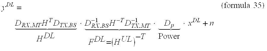
- Note that the introduction of D p allows this model to support other downlink strategies such as channel orthogonalization and, more generally, power control in the downlink.
- The linear model presented above lends itself to several useful interpretations and highlights the origin of the MUI:
- The effect of channel pre-filtering may be altered by the two diagonal matrices appearing between H T and H−T. This is due to transceiver effects at the BS. What causes MUI is the BS non-reciprocity: DTX,BS·(DRX,BS)−1 is not equal to the identity matrix multiplied by a scalar, although this product is diagonal. However, the identity matrix, multiplied by an arbitrary complex scalar, could be “inserted” between HT and H−T without causing MUI.
- The terminal front-end effects (D TX,MT and DRX,MT) generally do not contribute to MUI. However, even with perfect BS reciprocity, DTX,MT and DRX,MT will result in scaling and rotation of the constellations received at the UT, which imposes the use of an equalizer at the UT. The power scaling matrix DP also contributes to amplitude modifications that must be equalized at the terminal. Note that the terminal equalizer is a conventional time-only equalizer (as opposed to space-time equalizers). This equalizer is also useful to compensate the unknown phase of the base station RF oscillator at TX time.
- The propagation matrix H in this model also includes the parts of the BS or terminals that are common to uplink and downlink, hence reciprocal. This is the case for the antennas and for any common component inserted between the antenna and the Tx/Rx switch (or circulator).
- In an embodiment of the system, the MUI introduced by the BS front-end can be avoided by a calibration method that allows measuring the D TX,BS·(DRX,BS)−1 product at the BS so that the mismatches can be pre-compensated digitally at the transmitter.
- The block diagram of the SDMA BS Transceiver with the calibration hardware is illustrated in FIG. 15. In this block diagram, the complex frequency response of each
transmitter 1510 1514 is represented by a single transfer function dTX,BS,a[n] 1530 1534, which is, for thetransmitter 1514 of antenna branch a, the concatenation (product) of the frequency response of the baseband section with the low pass equivalent of the IF/RF section frequency response. These terms are the diagonal elements of the DTX,BS[n] matrix. A similar definition holds for dRX,BS,a[n] 1540 1544. - Before calibration, the carrier frequency and the transceiver parameters that have an effect on the amplitude or phase response of the
transmitter 1510 1514 and/or receiver 1520 1524 are set. This includes attenuator, power level, pre-selection filters, carrier frequency, gain of variable gain amplifiers, etc. Note that this may require several calibrations for a given carrier frequency. Once the parameters are set, the frequency responses are assumed static. The calibration is achieved in two steps: TX-RX calibration and RX-only calibration. Note that all described calibration operations are complex. - In one step, the transmit-receive calibration is performed (measurement of D TX,BS·DRX,BS). A transmit/receive/
calibration switch 1550 1554 is put in calibration mode: T and R are connected, so as to realize a loopback connection where the transmitter signal is routed all the way from baseband to RF and back from RF to baseband in the receiver 1520 1524. The RFcalibration noise source 1580 is turned off. In each antenna branch, a suitable known signal sa (an OFDM symbol with low peak-to-average power ratio) is generated by the digital modem so as to measure the frequency response of the cascaded transmitter and receiver. With the usual assumptions of perfect synchronization and cyclic prefix length, the frequency domain received signal is: - r 1 k =D TX ·D RX ·s+n k (formula 36)
- where s=[s 1 . . . sA]T and nk is a noise vector, the main contribution of which comes from the LNA noise Figure 1560 1564. K measurements are taken, which is reflected by the index k. The DTX,BS·DRX,BS product can be estimated by averaging the K values of r1 k:

- In an additional step, there is only receive calibration (measurement of D RX,BS). The transmit/receive/
calibration switch 1550 1554 is connected so as to isolate the receiver 1520 1524 from both thetransmitter 1510 1514 and theantenna 1570 1574. Thecalibration noise source 1580 is turned on. Its excess noise ratio (ENR) is typically sufficient to exceed the thermal noise generated by theLNAs 1560 1564 by 20 dB or more. The signal is sampled and measured at baseband in the receiver 1520 1524 of all antenna branches substantially simultaneously, which is advantageous for perfect phase calibration. The received frequency domain signal is: - r 2 k =D RX,BS ·n ref k +n k (formula 38)
- where n ref is the reference noise injected at RF, substantially identical at the input of all antenna branches. DRX,BS cannot be extracted directly, even by averaging, since nref appears as a multiplicative term. However, since an identical error coefficient in all antenna branches is allowed, nref can be eliminated by using the output of one of the antenna branches as reference and dividing the outputs of all branches by this reference value. Without loss of generality, we will take the signal in the first antenna branch r2,1 k as reference. This division operation yields:

- If the reference noise n ref is much larger than the receiver noise n, this reduces after averaging K measurements to:

- which is a vector containing the frequency responses of the receiver branches with a complex error coefficient, common to all antenna branches.
- In the division process, the r 2,1 k term is normally dominated by the reference noise multiplied by the frequency response dRX,BS,1 of the receiver chain of the first antenna branch. The magnitude of this frequency response is by design non-zero since the filters have low ripple and are calibrated in their passband. However, the amplitude of this term can be shown to be Rayleigh distributed and, hence, can in some cases be very low. It is therefore advantageous to substantially eliminate these values before the averaging process since the
non-correlated LNA noise 1560 1564 is dominant in these cases. A suitable criteria is to remove from the averaging process those realizations where the absolute value of r2,1 k is smaller than 0.15 . . . 0.25 times its mean value. Finally, the desired value is given by: - a./(c)2 ≅d RX,BS,1 2 ·diag(D TX,BS ·D RX,BS −1) (formula 41)
- where ./ stands for element-wise division. These are the values that, in some embodiments, are pre-compensated digitally before transmission. The unknown d RX,BS,1 2 factor is substantially identical in all branches, but this does not introduce MUI.
- A variance analysis of the estimation error of the D RX,BS·(DRX,BS)−1 product shows that with very mild parameter setting (20 dB ENR, 64 point FFT and 32 averages), one reaches an amplitude variance of 0.0008 and a phase variance of 0.0009. At 1 sigma, this corresponds to 0.24 dB amplitude and 1.72° phase differences. This can easily be improved with higher ENR ratio and/or more averaging. These values were obtained for errors before calibration as large as ±3 dB for the amplitude and ±π for the phase.
- FIG. 16 shows the BER degradations with and without calibration. ‘5 degr. & 0.7 dB reciprocity mismatch’ indicates that both the phase and amplitude mismatches described above were introduced (a difficult matching requirement for complete TX and RX chain). Note that the 4-user case at a BER of 10 −3 is not targeted because the required SNR is higher than 25 dB, even with ideal calibration.
- Although this calibration method relieves the TX and RX chain from any matching requirement, it does introduce some matching requirement on the calibration hardware. For example:
- The splitter ( 1590 in FIG. 15) outputs are matched between branches
- The directional couplers are matched
- The TX/RX/calibration switch ( 1550 1554 in FIG. 15) are matched between branches
- Mismatches in the calibration hardware can be included in the model by including 4 additional diagonal matrices (T, R, A and C are indicated in FIG. 15):
- D TA (TX-to-Antenna switch transfer function)
- D TR (TX-to-RX switch transfer function)
- D AR (Antenna-to-RX switch transfer function)
- D CR (Calibr. Noise-to-RX transfer function)
- Then, the downlink model becomes:
- y DL =D RX,MT H T D TA D CR D TR −1 D AR −1 H −T D TX,MT −1 D p x DL +n (formula 42)
- The mismatches introduced by the calibration hardware is advantageously minimized. However, this matching requirement is limited to a few components and is easier to achieve than the transmitter and receiver matching required when no calibration is included (matching of overall transfer functions including filters, mixers, LO phases, amplifiers, etc . . .).
- An alternative way to solve the non-reciprocity problem is illustrated in FIG. 17. The meaning of the references is as follows: T1=complete TX transfer function (TF) until input of directional coupler #1 (DC 1); R1=complete RX TF from DC1 input until the end of RX1 (so T/
R switch 1740 1744 is included in T1 and R1); D1=TF of DC1 in the direct path; C1=TF from DC1 input, through coupled port until combined port of top splitter/combiner; T2, R2, D2 and C2 are similarly defined; TR=TF of reference TX until combined port of bottom splitter; and RR=TF from combined port of bottom splitter until the end of reference RX. - The
unknowns TX1 1710, RX1 1720,TX2 1714,RX2 1724 are to be determined. Measurements are taken fromTX1 1710 to RX-R 1730 and fromTX2 1714 to RX-R 1730, yielding MT1=T1×C1×RR and MT2=T2×C2×RR. Next, measurements are taken from TX-R 1734 to RX1 1720 and from TX-R 1734 toRX2 1724, yielding MR1=TR×C1×R1 and MR2=TR×C2×R2. In a following step, the ratio of TX over RX measurements is computed for each branch: - MT1/MR1=(T1×C1×RR)/(TR×C1×R1)=(T1/R1)×(RR/TR)
- MT2/MR2=(T2×C2×RR)/(TR×C2×R2)=(T2/R2)×(RR/TR)
- These ratios are the desired measurements (T1/R1) and (T2/R2) with a common multiplicative error (RR/TR), which typically does not affect the reciprocity.
- The measurement of the first branch is performed substantially simultaneously to the measurement of the second branch. The LO and sampling clock in the reference TX and RX are locked to the ones in the antenna branches. If needed, to measure the
TX1 1710 andTX2 1714, the FDMA scheme with the sub-carriers can be used (e.g., odd sub-carriers from TX1, even sub-carriers from TX2). This approach offers several advantages: nothing needs to be calibrated or matched; compatibility with DBD3 (shared HW in Tx and Rx); can be used for more than 2 branches; no 4-position switch.
Claims (42)
Priority Applications (2)
| Application Number | Priority Date | Filing Date | Title |
|---|---|---|---|
| US10/645,858 US7961809B2 (en) | 2002-08-22 | 2003-08-20 | Method and apparatus for multi-user multi-input multi-output transmission |
| US13/115,486 US8219078B2 (en) | 2002-08-22 | 2011-05-25 | Method and apparatus for multi-user multi-input multi-output transmission |
Applications Claiming Priority (2)
| Application Number | Priority Date | Filing Date | Title |
|---|---|---|---|
| US40575902P | 2002-08-22 | 2002-08-22 | |
| US10/645,858 US7961809B2 (en) | 2002-08-22 | 2003-08-20 | Method and apparatus for multi-user multi-input multi-output transmission |
Related Child Applications (1)
| Application Number | Title | Priority Date | Filing Date |
|---|---|---|---|
| US13/115,486 Division US8219078B2 (en) | 2002-08-22 | 2011-05-25 | Method and apparatus for multi-user multi-input multi-output transmission |
Publications (2)
| Publication Number | Publication Date |
|---|---|
| US20040252632A1 true US20040252632A1 (en) | 2004-12-16 |
| US7961809B2 US7961809B2 (en) | 2011-06-14 |
Family
ID=31188707
Family Applications (2)
| Application Number | Title | Priority Date | Filing Date |
|---|---|---|---|
| US10/645,858 Expired - Fee Related US7961809B2 (en) | 2002-08-22 | 2003-08-20 | Method and apparatus for multi-user multi-input multi-output transmission |
| US13/115,486 Expired - Fee Related US8219078B2 (en) | 2002-08-22 | 2011-05-25 | Method and apparatus for multi-user multi-input multi-output transmission |
Family Applications After (1)
| Application Number | Title | Priority Date | Filing Date |
|---|---|---|---|
| US13/115,486 Expired - Fee Related US8219078B2 (en) | 2002-08-22 | 2011-05-25 | Method and apparatus for multi-user multi-input multi-output transmission |
Country Status (4)
| Country | Link |
|---|---|
| US (2) | US7961809B2 (en) |
| EP (1) | EP1392004B1 (en) |
| AT (1) | ATE421809T1 (en) |
| DE (1) | DE60325921D1 (en) |
Cited By (110)
| Publication number | Priority date | Publication date | Assignee | Title |
|---|---|---|---|---|
| US20040121753A1 (en) * | 2002-04-22 | 2004-06-24 | Cognio, Inc. | Multiple-Input Multiple-Output Radio Transceiver |
| US20040176097A1 (en) * | 2003-02-06 | 2004-09-09 | Fiona Wilson | Allocation of sub channels of MIMO channels of a wireless network |
| US20040184398A1 (en) * | 2003-03-20 | 2004-09-23 | Walton Jay Rod | Transmission mode selection for data transmission in a multi-channel communication system |
| US20050009483A1 (en) * | 2002-12-20 | 2005-01-13 | Texas Instruments Incorporated | Method for calibrating automatic gain control in wireless devices |
| US20050095996A1 (en) * | 2003-11-05 | 2005-05-05 | Sony Corporation | Wireless communications system, wireless communications method, and wireless communications apparatus |
| US20050135497A1 (en) * | 2003-12-22 | 2005-06-23 | Kwang-Soon Kim | Adaptive transmitting and receiving device and method in wireless communication system using frequency division duplexing |
| US20050260963A1 (en) * | 2004-05-19 | 2005-11-24 | Motorola, Inc. | Receiver system and method for wideband self test |
| US20060039489A1 (en) * | 2004-08-17 | 2006-02-23 | Texas Instruments Incorporated | Method and apparatus for providing closed-loop transmit precoding |
| US20060084400A1 (en) * | 2004-10-15 | 2006-04-20 | Nokia Corporation | Simplified practical rank and mechanism, and associated method, to adapt MIMO modulation in a multi-carrier system with feedback |
| US20060109923A1 (en) * | 2004-10-20 | 2006-05-25 | Sean Cai | Subcarrier cluster-based power control in wireless communications |
| US20060128318A1 (en) * | 2002-09-10 | 2006-06-15 | Luigi Agarossi | Transmission power optimization in ofdm wireless communication system |
| US20060141936A1 (en) * | 2003-01-10 | 2006-06-29 | Eric Auffret | Diversity system for measuring reception quality |
| US20060153319A1 (en) * | 2004-09-23 | 2006-07-13 | Interdigital Technology Corporation | Receiver hardware reduction for spatially independent signals and associated methods |
| US20060165008A1 (en) * | 2005-01-21 | 2006-07-27 | Qinghua Li | Techniques to manage channel prediction |
| US20060164972A1 (en) * | 2005-01-21 | 2006-07-27 | Samsung Electronics Co., Ltd. | Apparatus and method for downlink scheduling in a SDMA-enabled OFDMA wireless network |
| US20060182192A1 (en) * | 2005-01-21 | 2006-08-17 | Hiroaki Takano | Wireless communication system, wireless communication apparatus, wireless communication method, and computer program |
| WO2006099403A2 (en) * | 2005-03-11 | 2006-09-21 | Interdigital Technology Corporation | Communications device with adaptive decoding and associated methods |
| US20060223450A1 (en) * | 2005-03-29 | 2006-10-05 | Dacosta Behram M | Method and apparatus to resist fading in mimo and simo wireless systems |
| WO2006107888A2 (en) * | 2005-04-01 | 2006-10-12 | Interdigital Technology Corporation | Method and apparatus for singular value decomposition of a channel matrix |
| WO2007003977A1 (en) * | 2005-06-30 | 2007-01-11 | Nokia Corporation | Multi-stream fft for mimo-ofdm systems |
| US20070025464A1 (en) * | 2004-07-30 | 2007-02-01 | Perlman Stephen G | System and method for spatial-multiplexed tropospheric scatter communications |
| US7181205B1 (en) * | 2004-05-11 | 2007-02-20 | Rf Micro Devices, Inc. | I/Q calibration |
| US20070081450A1 (en) * | 2005-10-12 | 2007-04-12 | Shigenori Hayase | Wireless data communication system, wireless data communication method and communication apparatus |
| US20070149236A1 (en) * | 2005-12-27 | 2007-06-28 | Naden James M | Transmit power allocation in a distributed MIMO system |
| US20070177655A1 (en) * | 2005-12-05 | 2007-08-02 | Commissariat A L'energie Atomique | Method and device for selecting spreading parameters for an ofdm-cdma system |
| US20070259694A1 (en) * | 2006-04-25 | 2007-11-08 | Samsung Electronics Co., Ltd. | Apparatus and method for implementing SDMA in multi-user multi-antenna system |
| US20070280335A1 (en) * | 2006-06-01 | 2007-12-06 | Tae Joon Kim | Multi-input multi-output system and method for demodulating a transmitting vector in a receiver of the system |
| US20080009322A1 (en) * | 2006-07-05 | 2008-01-10 | Samsung Electronics Co., Ltd. | Radio resource allocating method and apparatus in adaptive antenna system |
| US20080032746A1 (en) * | 2006-08-07 | 2008-02-07 | Interdigital Technology Corporation | Method, apparatus and system for implementing multi-user virtual multiple-input multiple-output |
| US7352688B1 (en) * | 2002-12-31 | 2008-04-01 | Cisco Technology, Inc. | High data rate wireless bridging |
| US20080080631A1 (en) * | 2004-07-30 | 2008-04-03 | Antonio Forenza | System and method for ditributed input-distributed output wireless communications |
| US20080118004A1 (en) * | 2004-07-30 | 2008-05-22 | Antonio Forenza | System and method for distributed input-distributed output wireless communications |
| US20080130790A1 (en) * | 2004-07-30 | 2008-06-05 | Antionio Forenza | System and method for distributed input distributed output wireless communications |
| US20090010221A1 (en) * | 2003-12-15 | 2009-01-08 | Boris Ginzburg | Method of multiple-input-multiple-output wireless communication |
| US20090067402A1 (en) * | 2007-08-20 | 2009-03-12 | Antonio Forenza | System and Method For Distributed Input-Distributed Output Wireless Communications |
| US20090077395A1 (en) * | 2007-09-17 | 2009-03-19 | Jr-Shian Tsai | Techniques for communications power management based on system states |
| US20090175363A1 (en) * | 2005-05-27 | 2009-07-09 | Ari Hottinen | Assignment of sub-channels to channels in a multi transmission-channel system |
| US20090175375A1 (en) * | 2005-11-23 | 2009-07-09 | Nokia Corporation | Joint Optimization of Linear Pre-Filtering and Nonlinear Vector Perturbation for MIMO Multiuser Precoding |
| US20090180778A1 (en) * | 2008-01-04 | 2009-07-16 | Icu Research And Industrial Cooperation Group | Forward Discrete/Inverse-Discrete Fourier Transform Device and Method for Optical OFDM Communication and Transmitting and Receiving Apparatus Comprising the Device |
| US20090180573A1 (en) * | 2008-01-10 | 2009-07-16 | Viasat, Inc. | Receiver-based frequency response estimation |
| US20090185577A1 (en) * | 2005-04-01 | 2009-07-23 | Ntt Docomo, Inc. | Transmission apparatus and transmission method |
| EP2110757A1 (en) | 2008-04-14 | 2009-10-21 | Imec | Device and method for parallelizing multicarrier demodulation |
| US20100046357A1 (en) * | 2008-08-20 | 2010-02-25 | Qualcomm Incorporated | USING CDMA TO SEND UPLINK SIGNALS IN WLANs |
| US20100054113A1 (en) * | 2005-09-22 | 2010-03-04 | Technische Universität Ilmenau | Method for Selection of an Optimized Number of Subscribers in Mobile Radio Systems |
| US20100226458A1 (en) * | 2009-03-05 | 2010-09-09 | Telefonaktiebolaget L M Ericsson (Publ) | OFDM Spectral Control |
| US20100316163A1 (en) * | 2004-04-02 | 2010-12-16 | Antonio Forenza | System and method for DIDO precoding interpolation in multicarrier systems |
| US20110003608A1 (en) * | 2004-04-02 | 2011-01-06 | Antonio Forenza | System and method for managing handoff of a client between different distributed-input-distributed-output (DIDO) networks based on detected velocity of the client |
| US20110002371A1 (en) * | 2004-04-02 | 2011-01-06 | Antonio Forenza | System and method for adjusting DIDO interference cancellation based on signal strength measurements |
| US20110003607A1 (en) * | 2004-04-02 | 2011-01-06 | Antonio Forenza | Interference management, handoff, power control and link adaptation in distributed-input distributed-output (DIDO) communication systems |
| US20110044193A1 (en) * | 2004-04-02 | 2011-02-24 | Antonio Forenza | Systems and methods to coordinate transmissions in distributed wireless systems via user clustering |
| US20110222620A1 (en) * | 2004-12-14 | 2011-09-15 | Hansen Christopher J | Method and System for Frame Formats for MIMO Channel Measurement Exchange |
| US8134976B2 (en) | 2002-10-25 | 2012-03-13 | Qualcomm Incorporated | Channel calibration for a time division duplexed communication system |
| US8145179B2 (en) | 2002-10-25 | 2012-03-27 | Qualcomm Incorporated | Data detection and demodulation for wireless communication systems |
| US8147339B1 (en) | 2007-12-15 | 2012-04-03 | Gaikai Inc. | Systems and methods of serving game video |
| US8169944B2 (en) | 2002-10-25 | 2012-05-01 | Qualcomm Incorporated | Random access for wireless multiple-access communication systems |
| US8194770B2 (en) | 2002-08-27 | 2012-06-05 | Qualcomm Incorporated | Coded MIMO systems with selective channel inversion applied per eigenmode |
| US8203978B2 (en) | 2002-10-25 | 2012-06-19 | Qualcomm Incorporated | Multi-mode terminal in a wireless MIMO system |
| US8208364B2 (en) | 2002-10-25 | 2012-06-26 | Qualcomm Incorporated | MIMO system with multiple spatial multiplexing modes |
| US8218609B2 (en) | 2002-10-25 | 2012-07-10 | Qualcomm Incorporated | Closed-loop rate control for a multi-channel communication system |
| US8320301B2 (en) | 2002-10-25 | 2012-11-27 | Qualcomm Incorporated | MIMO WLAN system |
| US8358714B2 (en) | 2005-06-16 | 2013-01-22 | Qualcomm Incorporated | Coding and modulation for multiple data streams in a communication system |
| US8363634B2 (en) | 2006-06-08 | 2013-01-29 | Hitachi, Ltd. | Wireless communication method, wireless communication apparatus and access point apparatus |
| US20130163505A1 (en) * | 2011-12-23 | 2013-06-27 | Airspan Networks Inc. | System and Method for Determining a Communications Schedule for Relay Nodes of a Wireless Relay Network |
| US8506402B2 (en) | 2009-06-01 | 2013-08-13 | Sony Computer Entertainment America Llc | Game execution environments |
| US20130223382A1 (en) * | 2009-11-14 | 2013-08-29 | Qualcomm Incorporated | Method and apparatus for managing client initiated transmissions in multiple-user communication schemes |
| US8560331B1 (en) | 2010-08-02 | 2013-10-15 | Sony Computer Entertainment America Llc | Audio acceleration |
| US8570988B2 (en) | 2002-10-25 | 2013-10-29 | Qualcomm Incorporated | Channel calibration for a time division duplexed communication system |
| US8613673B2 (en) | 2008-12-15 | 2013-12-24 | Sony Computer Entertainment America Llc | Intelligent game loading |
| CN103501193A (en) * | 2007-08-20 | 2014-01-08 | 瑞登有限责任公司 | Method for compensating for MU-MAS and dynamically adapting to MU-MAS |
| US8654815B1 (en) | 2004-04-02 | 2014-02-18 | Rearden, Llc | System and method for distributed antenna wireless communications |
| US20140192932A1 (en) * | 2004-10-06 | 2014-07-10 | Broadcom Corporation | Method and System for Implementing a Single Weight Spatial Multiplexing (SM) MIMO System |
| US8840476B2 (en) | 2008-12-15 | 2014-09-23 | Sony Computer Entertainment America Llc | Dual-mode program execution |
| US8855226B2 (en) | 2005-05-12 | 2014-10-07 | Qualcomm Incorporated | Rate selection with margin sharing |
| US8873365B2 (en) | 2002-10-25 | 2014-10-28 | Qualcomm Incorporated | Transmit diversity processing for a multi-antenna communication system |
| US8888592B1 (en) | 2009-06-01 | 2014-11-18 | Sony Computer Entertainment America Llc | Voice overlay |
| US8926435B2 (en) | 2008-12-15 | 2015-01-06 | Sony Computer Entertainment America Llc | Dual-mode program execution |
| US8968087B1 (en) | 2009-06-01 | 2015-03-03 | Sony Computer Entertainment America Llc | Video game overlay |
| US8989155B2 (en) | 2007-08-20 | 2015-03-24 | Rearden, Llc | Systems and methods for wireless backhaul in distributed-input distributed-output wireless systems |
| WO2015131116A1 (en) * | 2014-02-27 | 2015-09-03 | Huawei Technologies Co., Ltd. | System and method for multiple-input and multiple-output (mimo) full-duplex precoding structures |
| US9154274B2 (en) | 2002-10-25 | 2015-10-06 | Qualcomm Incorporated | OFDM communication system with multiple OFDM symbol sizes |
| US9312935B2 (en) | 2002-10-25 | 2016-04-12 | Qualcomm Incorporated | Pilots for MIMO communication systems |
| US9312929B2 (en) | 2004-04-02 | 2016-04-12 | Rearden, Llc | System and methods to compensate for Doppler effects in multi-user (MU) multiple antenna systems (MAS) |
| US20160173175A1 (en) * | 2013-06-10 | 2016-06-16 | Sharp Kabushiki Kaisha | Base station apparatus, terminal apparatus, wireless communication system, and integrated circuit |
| WO2016098369A1 (en) * | 2014-12-15 | 2016-06-23 | Nec Corporation | Method and system for mimo communication |
| AU2014200745B2 (en) * | 2007-08-20 | 2016-09-29 | Rearden, Llc | System and method for distributed input distributed output wireless communications |
| US9473269B2 (en) | 2003-12-01 | 2016-10-18 | Qualcomm Incorporated | Method and apparatus for providing an efficient control channel structure in a wireless communication system |
| US20170041891A1 (en) * | 2014-04-22 | 2017-02-09 | Lg Electronics Inc. | Method and apparatus for acquiring synchronization for device to device terminal in wireless communication system |
| US9685997B2 (en) | 2007-08-20 | 2017-06-20 | Rearden, Llc | Systems and methods to enhance spatial diversity in distributed-input distributed-output wireless systems |
| US9826537B2 (en) | 2004-04-02 | 2017-11-21 | Rearden, Llc | System and method for managing inter-cluster handoff of clients which traverse multiple DIDO clusters |
| US9878240B2 (en) | 2010-09-13 | 2018-01-30 | Sony Interactive Entertainment America Llc | Add-on management methods |
| US9923657B2 (en) | 2013-03-12 | 2018-03-20 | Rearden, Llc | Systems and methods for exploiting inter-cell multiplexing gain in wireless cellular systems via distributed input distributed output technology |
| US9973246B2 (en) | 2013-03-12 | 2018-05-15 | Rearden, Llc | Systems and methods for exploiting inter-cell multiplexing gain in wireless cellular systems via distributed input distributed output technology |
| US10164698B2 (en) | 2013-03-12 | 2018-12-25 | Rearden, Llc | Systems and methods for exploiting inter-cell multiplexing gain in wireless cellular systems via distributed input distributed output technology |
| US10187133B2 (en) | 2004-04-02 | 2019-01-22 | Rearden, Llc | System and method for power control and antenna grouping in a distributed-input-distributed-output (DIDO) network |
| US10194346B2 (en) | 2012-11-26 | 2019-01-29 | Rearden, Llc | Systems and methods for exploiting inter-cell multiplexing gain in wireless cellular systems via distributed input distributed output technology |
| US10277290B2 (en) | 2004-04-02 | 2019-04-30 | Rearden, Llc | Systems and methods to exploit areas of coherence in wireless systems |
| US10425134B2 (en) | 2004-04-02 | 2019-09-24 | Rearden, Llc | System and methods for planned evolution and obsolescence of multiuser spectrum |
| US10488535B2 (en) | 2013-03-12 | 2019-11-26 | Rearden, Llc | Apparatus and method for capturing still images and video using diffraction coded imaging techniques |
| US10547358B2 (en) | 2013-03-15 | 2020-01-28 | Rearden, Llc | Systems and methods for radio frequency calibration exploiting channel reciprocity in distributed input distributed output wireless communications |
| US10749582B2 (en) | 2004-04-02 | 2020-08-18 | Rearden, Llc | Systems and methods to coordinate transmissions in distributed wireless systems via user clustering |
| US10886979B2 (en) | 2004-04-02 | 2021-01-05 | Rearden, Llc | System and method for link adaptation in DIDO multicarrier systems |
| US10985811B2 (en) | 2004-04-02 | 2021-04-20 | Rearden, Llc | System and method for distributed antenna wireless communications |
| US11050468B2 (en) | 2014-04-16 | 2021-06-29 | Rearden, Llc | Systems and methods for mitigating interference within actively used spectrum |
| US11189917B2 (en) | 2014-04-16 | 2021-11-30 | Rearden, Llc | Systems and methods for distributing radioheads |
| US11190947B2 (en) | 2014-04-16 | 2021-11-30 | Rearden, Llc | Systems and methods for concurrent spectrum usage within actively used spectrum |
| US11290162B2 (en) | 2014-04-16 | 2022-03-29 | Rearden, Llc | Systems and methods for mitigating interference within actively used spectrum |
| US11309943B2 (en) | 2004-04-02 | 2022-04-19 | Rearden, Llc | System and methods for planned evolution and obsolescence of multiuser spectrum |
| US11323157B2 (en) * | 2014-12-16 | 2022-05-03 | Fujitsu Limited | Downlink channel estimation method and apparatus based on sounding reference signal and communications system |
| US11394436B2 (en) | 2004-04-02 | 2022-07-19 | Rearden, Llc | System and method for distributed antenna wireless communications |
| US11451275B2 (en) | 2004-04-02 | 2022-09-20 | Rearden, Llc | System and method for distributed antenna wireless communications |
Families Citing this family (24)
| Publication number | Priority date | Publication date | Assignee | Title |
|---|---|---|---|---|
| WO2005081439A1 (en) | 2004-02-13 | 2005-09-01 | Neocific, Inc. | Methods and apparatus for multi-carrier communication systems with adaptive transmission and feedback |
| EP1791278A1 (en) | 2005-11-29 | 2007-05-30 | Interuniversitair Microelektronica Centrum (IMEC) | Device and method for calibrating MIMO systems |
| KR101119228B1 (en) * | 2006-04-27 | 2012-03-21 | 레이스팬 코포레이션 | Antennas, devices and systems based on metamaterial structures |
| WO2008024993A2 (en) * | 2006-08-25 | 2008-02-28 | Rayspan Corporation | Antennas based on metamaterial structures |
| US8271266B2 (en) * | 2006-08-31 | 2012-09-18 | Waggner Edstrom Worldwide, Inc. | Media content assessment and control systems |
| US8340957B2 (en) * | 2006-08-31 | 2012-12-25 | Waggener Edstrom Worldwide, Inc. | Media content assessment and control systems |
| EP1937006A1 (en) * | 2006-12-22 | 2008-06-25 | Siemens Networks GmbH & Co. KG | Multi-antenna relay station with two-way channel |
| WO2008115881A1 (en) * | 2007-03-16 | 2008-09-25 | Rayspan Corporation | Metamaterial antenna arrays with radiation pattern shaping and beam switching |
| TWI376838B (en) * | 2007-10-11 | 2012-11-11 | Tyco Electronics Services Gmbh | Single-layer metallization and via-less metamaterial structures |
| US20090124290A1 (en) * | 2007-11-09 | 2009-05-14 | Zhifeng Tao | Antenna Selection for SDMA Transmissions in OFDMA Networks |
| JP4471006B2 (en) * | 2008-02-04 | 2010-06-02 | ソニー株式会社 | Wireless communication apparatus, antenna calibration method, and program |
| KR101630868B1 (en) | 2008-03-04 | 2016-06-27 | 코닌클리케 필립스 엔.브이. | Signaling of transmission settings in multi-user systems |
| KR20110021920A (en) * | 2008-06-27 | 2011-03-04 | 교세라 가부시키가이샤 | Wireless communication device and wireless communication method |
| WO2009157521A1 (en) * | 2008-06-27 | 2009-12-30 | 京セラ株式会社 | Radio communication device and radio communication method |
| WO2009157523A1 (en) * | 2008-06-27 | 2009-12-30 | 京セラ株式会社 | Wireless communication device and wireless communication method |
| JP2010081396A (en) * | 2008-09-26 | 2010-04-08 | Kyocera Corp | Wireless communication apparatus and wireless communication method |
| EP2182653A1 (en) | 2008-10-31 | 2010-05-05 | Nokia Siemens Networks GmbH & Co. KG | Method of transmitting data in a radio network, radio network and receiving station. |
| US8345797B1 (en) * | 2008-12-04 | 2013-01-01 | Marvell International Ltd. | Method and apparatus for generating steering matrices for beamforming |
| JP5553903B2 (en) * | 2009-10-26 | 2014-07-23 | エレクトロビット・システム・テスト・オサケユキテュア | Over-the-air testing method and system |
| JP5629219B2 (en) * | 2011-01-13 | 2014-11-19 | スパンション エルエルシー | COMMUNICATION DEVICE, COMMUNICATION SYSTEM, AND COMMUNICATION METHOD |
| JP2014049822A (en) * | 2012-08-29 | 2014-03-17 | Tokyo Institute Of Technology | Reception device, reception method and program |
| CN103259577B (en) * | 2013-04-27 | 2016-01-13 | 上海交通大学 | A kind of relay system source and relay robustness united signal processing method |
| WO2016137898A1 (en) * | 2015-02-27 | 2016-09-01 | Ziva Corporation | Time reversal in wireless communications |
| CN105827293B (en) * | 2016-04-06 | 2018-07-27 | 郑州大学 | A kind of linear force zero method for precoding of multi-user's generalized spatial modulation system |
Citations (22)
| Publication number | Priority date | Publication date | Assignee | Title |
|---|---|---|---|---|
| US20020154705A1 (en) * | 2000-03-22 | 2002-10-24 | Walton Jay R. | High efficiency high performance communications system employing multi-carrier modulation |
| US20020159506A1 (en) * | 1997-02-24 | 2002-10-31 | Siavash Alamouti | Vertical adaptive antenna array for a discrete multitone spread spectrum communications system |
| US20020165626A1 (en) * | 2000-11-06 | 2002-11-07 | Hammons A. Roger | Space-time coded OFDM system for MMDS applications |
| US20020191703A1 (en) * | 2001-03-23 | 2002-12-19 | Fuyun Ling | Method and apparatus for utilizing channel state information in a wireless communication system |
| US20030021332A1 (en) * | 2001-05-21 | 2003-01-30 | Ye Li | Channel estimation for wireless systems with multiple transmit antennas |
| US20030026348A1 (en) * | 2001-06-07 | 2003-02-06 | National University Of Singapore | Wireless communication apparatus and method |
| US20030035491A1 (en) * | 2001-05-11 | 2003-02-20 | Walton Jay R. | Method and apparatus for processing data in a multiple-input multiple-output (MIMO) communication system utilizing channel state information |
| US20030048856A1 (en) * | 2001-05-17 | 2003-03-13 | Ketchum John W. | Method and apparatus for processing data for transmission in a multi-channel communication system using selective channel inversion |
| US20030072382A1 (en) * | 1996-08-29 | 2003-04-17 | Cisco Systems, Inc. | Spatio-temporal processing for communication |
| US20030099304A1 (en) * | 2001-11-28 | 2003-05-29 | Dhananjay Gore | System and method for transmit diversity base upon transmission channel delay spread |
| US20030103584A1 (en) * | 2001-12-03 | 2003-06-05 | Bjerke Bjorn A. | Iterative detection and decoding for a MIMO-OFDM system |
| US20030112880A1 (en) * | 2001-05-17 | 2003-06-19 | Walton Jay R. | Method and apparatus for processing data for transmission in a multi-channel communication system using selective channel inversion |
| US20030147476A1 (en) * | 2002-01-25 | 2003-08-07 | Xiaoqiang Ma | Expectation-maximization-based channel estimation and signal detection for wireless communications systems |
| US20030165189A1 (en) * | 2002-03-01 | 2003-09-04 | Tamer Kadous | Data transmission with non-uniform distribution of data rates for a multiple-input multiple-output (mimo) system |
| US20030169824A1 (en) * | 2002-03-08 | 2003-09-11 | Naftali Chayat | Orthogonal division multiple access technique incorporating single carrier and OFDM signals |
| US20030185310A1 (en) * | 2002-03-27 | 2003-10-02 | Ketchum John W. | Precoding for a multipath channel in a MIMO system |
| US20030189999A1 (en) * | 2002-04-09 | 2003-10-09 | Tamer Kadous | Ordered successive interference cancellation receiver processing for multipath channels |
| US20030235255A1 (en) * | 2002-06-24 | 2003-12-25 | Ketchum John W. | Signal processing with channel eigenmode decomposition and channel inversion for MIMO systems |
| US20040001564A1 (en) * | 2002-06-24 | 2004-01-01 | Albert Chan | Reduced complexity receiver for space-time- bit-interleaved coded modulation |
| US20040071222A1 (en) * | 2001-06-07 | 2004-04-15 | National University Of Singapore | Wireless communication apparatus and method |
| US6937665B1 (en) * | 1999-04-19 | 2005-08-30 | Interuniversitaire Micron Elektronica Centrum | Method and apparatus for multi-user transmission |
| US7099413B2 (en) * | 2000-02-07 | 2006-08-29 | At&T Corp. | Method for near optimal joint channel estimation and data detection for COFDM systems |
Family Cites Families (16)
| Publication number | Priority date | Publication date | Assignee | Title |
|---|---|---|---|---|
| DE4326523A1 (en) * | 1993-08-06 | 1995-02-09 | Siemens Ag | Universal mobile telecommunication system |
| US6101399A (en) * | 1995-02-22 | 2000-08-08 | The Board Of Trustees Of The Leland Stanford Jr. University | Adaptive beam forming for transmitter operation in a wireless communication system |
| EP0762541A3 (en) * | 1995-08-29 | 2000-01-12 | DaimlerChrysler AG | Device for calibrating and testing transmit/receive moduls in an active electronically phased array antenna |
| US5835850A (en) * | 1996-08-12 | 1998-11-10 | At&T Corp | Self-testing transceiver |
| US6009317A (en) * | 1997-01-17 | 1999-12-28 | Ericsson Inc. | Method and apparatus for compensating for imbalances between quadrature signals |
| US6118811A (en) * | 1997-07-31 | 2000-09-12 | Raytheon Company | Self-calibrating, self-correcting transceivers and methods |
| US6397042B1 (en) * | 1998-03-06 | 2002-05-28 | Texas Instruments Incorporated | Self test of an electronic device |
| US6832075B1 (en) * | 1999-10-05 | 2004-12-14 | Ericsson Inc. | Method for calibrating the power output of a mobile device |
| US6968167B1 (en) * | 1999-10-21 | 2005-11-22 | Broadcom Corporation | Adaptive radio transceiver with calibration |
| EP1148654A1 (en) * | 2000-04-18 | 2001-10-24 | Infineon Technologies AG | Transmitter receiver |
| US6985434B2 (en) * | 2000-09-01 | 2006-01-10 | Nortel Networks Limited | Adaptive time diversity and spatial diversity for OFDM |
| US6870808B1 (en) * | 2000-10-18 | 2005-03-22 | Adaptix, Inc. | Channel allocation in broadband orthogonal frequency-division multiple-access/space-division multiple-access networks |
| US7233629B2 (en) * | 2001-06-29 | 2007-06-19 | Nokia Corporation | Adjusting a receiver |
| US6771709B2 (en) * | 2001-10-16 | 2004-08-03 | Her Majesty The Queen In Right Of Canada, As Represented By The Minister Of Industry | System and method for direct transmitter self-calibration |
| US7313198B2 (en) * | 2002-03-12 | 2007-12-25 | Motorola Inc. | Self calibrating transmit path correction system |
| US7020220B2 (en) * | 2002-06-18 | 2006-03-28 | Broadcom Corporation | Digital estimation and correction of I/Q mismatch in direct conversion receivers |
-
2003
- 2003-07-18 DE DE60325921T patent/DE60325921D1/en not_active Expired - Lifetime
- 2003-07-18 EP EP03447187A patent/EP1392004B1/en not_active Expired - Lifetime
- 2003-07-18 AT AT03447187T patent/ATE421809T1/en not_active IP Right Cessation
- 2003-08-20 US US10/645,858 patent/US7961809B2/en not_active Expired - Fee Related
-
2011
- 2011-05-25 US US13/115,486 patent/US8219078B2/en not_active Expired - Fee Related
Patent Citations (22)
| Publication number | Priority date | Publication date | Assignee | Title |
|---|---|---|---|---|
| US20030072382A1 (en) * | 1996-08-29 | 2003-04-17 | Cisco Systems, Inc. | Spatio-temporal processing for communication |
| US20020159506A1 (en) * | 1997-02-24 | 2002-10-31 | Siavash Alamouti | Vertical adaptive antenna array for a discrete multitone spread spectrum communications system |
| US6937665B1 (en) * | 1999-04-19 | 2005-08-30 | Interuniversitaire Micron Elektronica Centrum | Method and apparatus for multi-user transmission |
| US7099413B2 (en) * | 2000-02-07 | 2006-08-29 | At&T Corp. | Method for near optimal joint channel estimation and data detection for COFDM systems |
| US20020154705A1 (en) * | 2000-03-22 | 2002-10-24 | Walton Jay R. | High efficiency high performance communications system employing multi-carrier modulation |
| US20020165626A1 (en) * | 2000-11-06 | 2002-11-07 | Hammons A. Roger | Space-time coded OFDM system for MMDS applications |
| US20020191703A1 (en) * | 2001-03-23 | 2002-12-19 | Fuyun Ling | Method and apparatus for utilizing channel state information in a wireless communication system |
| US20030035491A1 (en) * | 2001-05-11 | 2003-02-20 | Walton Jay R. | Method and apparatus for processing data in a multiple-input multiple-output (MIMO) communication system utilizing channel state information |
| US20030048856A1 (en) * | 2001-05-17 | 2003-03-13 | Ketchum John W. | Method and apparatus for processing data for transmission in a multi-channel communication system using selective channel inversion |
| US20030112880A1 (en) * | 2001-05-17 | 2003-06-19 | Walton Jay R. | Method and apparatus for processing data for transmission in a multi-channel communication system using selective channel inversion |
| US20030021332A1 (en) * | 2001-05-21 | 2003-01-30 | Ye Li | Channel estimation for wireless systems with multiple transmit antennas |
| US20040071222A1 (en) * | 2001-06-07 | 2004-04-15 | National University Of Singapore | Wireless communication apparatus and method |
| US20030026348A1 (en) * | 2001-06-07 | 2003-02-06 | National University Of Singapore | Wireless communication apparatus and method |
| US20030099304A1 (en) * | 2001-11-28 | 2003-05-29 | Dhananjay Gore | System and method for transmit diversity base upon transmission channel delay spread |
| US20030103584A1 (en) * | 2001-12-03 | 2003-06-05 | Bjerke Bjorn A. | Iterative detection and decoding for a MIMO-OFDM system |
| US20030147476A1 (en) * | 2002-01-25 | 2003-08-07 | Xiaoqiang Ma | Expectation-maximization-based channel estimation and signal detection for wireless communications systems |
| US20030165189A1 (en) * | 2002-03-01 | 2003-09-04 | Tamer Kadous | Data transmission with non-uniform distribution of data rates for a multiple-input multiple-output (mimo) system |
| US20030169824A1 (en) * | 2002-03-08 | 2003-09-11 | Naftali Chayat | Orthogonal division multiple access technique incorporating single carrier and OFDM signals |
| US20030185310A1 (en) * | 2002-03-27 | 2003-10-02 | Ketchum John W. | Precoding for a multipath channel in a MIMO system |
| US20030189999A1 (en) * | 2002-04-09 | 2003-10-09 | Tamer Kadous | Ordered successive interference cancellation receiver processing for multipath channels |
| US20030235255A1 (en) * | 2002-06-24 | 2003-12-25 | Ketchum John W. | Signal processing with channel eigenmode decomposition and channel inversion for MIMO systems |
| US20040001564A1 (en) * | 2002-06-24 | 2004-01-01 | Albert Chan | Reduced complexity receiver for space-time- bit-interleaved coded modulation |
Cited By (245)
| Publication number | Priority date | Publication date | Assignee | Title |
|---|---|---|---|---|
| US7636554B2 (en) | 2002-04-22 | 2009-12-22 | Ipr Licensing, Inc. | Multiple-input multiple-output radio transceiver |
| US10326501B2 (en) | 2002-04-22 | 2019-06-18 | Ipr Licensing, Inc. | Multiple-input multiple-output radio transceiver |
| US20100099366A1 (en) * | 2002-04-22 | 2010-04-22 | Ipr Licensing, Inc. | Multiple-input multiple-output radio transceiver |
| US9374139B2 (en) | 2002-04-22 | 2016-06-21 | Ipr Licensing, Inc. | Multiple-input multiple-output radio transceiver |
| US20040121753A1 (en) * | 2002-04-22 | 2004-06-24 | Cognio, Inc. | Multiple-Input Multiple-Output Radio Transceiver |
| US8463199B2 (en) | 2002-04-22 | 2013-06-11 | Ipr Licensing, Inc. | Multiple-input multiple-output radio transceiver |
| US8194770B2 (en) | 2002-08-27 | 2012-06-05 | Qualcomm Incorporated | Coded MIMO systems with selective channel inversion applied per eigenmode |
| US20060128318A1 (en) * | 2002-09-10 | 2006-06-15 | Luigi Agarossi | Transmission power optimization in ofdm wireless communication system |
| US7561558B2 (en) * | 2002-09-10 | 2009-07-14 | Koninklijke Philips Electronics N.V. | Transmission power optimization of OFDM wireless communication system |
| US8462643B2 (en) | 2002-10-25 | 2013-06-11 | Qualcomm Incorporated | MIMO WLAN system |
| US8169944B2 (en) | 2002-10-25 | 2012-05-01 | Qualcomm Incorporated | Random access for wireless multiple-access communication systems |
| US8934329B2 (en) | 2002-10-25 | 2015-01-13 | Qualcomm Incorporated | Transmit diversity processing for a multi-antenna communication system |
| US9013974B2 (en) | 2002-10-25 | 2015-04-21 | Qualcomm Incorporated | MIMO WLAN system |
| US8483188B2 (en) | 2002-10-25 | 2013-07-09 | Qualcomm Incorporated | MIMO system with multiple spatial multiplexing modes |
| US8355313B2 (en) | 2002-10-25 | 2013-01-15 | Qualcomm Incorporated | MIMO system with multiple spatial multiplexing modes |
| US9031097B2 (en) | 2002-10-25 | 2015-05-12 | Qualcomm Incorporated | MIMO system with multiple spatial multiplexing modes |
| US9048892B2 (en) | 2002-10-25 | 2015-06-02 | Qualcomm Incorporated | MIMO system with multiple spatial multiplexing modes |
| US8320301B2 (en) | 2002-10-25 | 2012-11-27 | Qualcomm Incorporated | MIMO WLAN system |
| US9154274B2 (en) | 2002-10-25 | 2015-10-06 | Qualcomm Incorporated | OFDM communication system with multiple OFDM symbol sizes |
| US9240871B2 (en) | 2002-10-25 | 2016-01-19 | Qualcomm Incorporated | MIMO WLAN system |
| US8218609B2 (en) | 2002-10-25 | 2012-07-10 | Qualcomm Incorporated | Closed-loop rate control for a multi-channel communication system |
| US8208364B2 (en) | 2002-10-25 | 2012-06-26 | Qualcomm Incorporated | MIMO system with multiple spatial multiplexing modes |
| US8203978B2 (en) | 2002-10-25 | 2012-06-19 | Qualcomm Incorporated | Multi-mode terminal in a wireless MIMO system |
| US8913529B2 (en) | 2002-10-25 | 2014-12-16 | Qualcomm Incorporated | MIMO WLAN system |
| US8711763B2 (en) | 2002-10-25 | 2014-04-29 | Qualcomm Incorporated | Random access for wireless multiple-access communication systems |
| US8170513B2 (en) | 2002-10-25 | 2012-05-01 | Qualcomm Incorporated | Data detection and demodulation for wireless communication systems |
| US9312935B2 (en) | 2002-10-25 | 2016-04-12 | Qualcomm Incorporated | Pilots for MIMO communication systems |
| US8873365B2 (en) | 2002-10-25 | 2014-10-28 | Qualcomm Incorporated | Transmit diversity processing for a multi-antenna communication system |
| US8145179B2 (en) | 2002-10-25 | 2012-03-27 | Qualcomm Incorporated | Data detection and demodulation for wireless communication systems |
| US8134976B2 (en) | 2002-10-25 | 2012-03-13 | Qualcomm Incorporated | Channel calibration for a time division duplexed communication system |
| US10382106B2 (en) | 2002-10-25 | 2019-08-13 | Qualcomm Incorporated | Pilots for MIMO communication systems |
| US9967005B2 (en) | 2002-10-25 | 2018-05-08 | Qualcomm Incorporated | Pilots for MIMO communication systems |
| US8570988B2 (en) | 2002-10-25 | 2013-10-29 | Qualcomm Incorporated | Channel calibration for a time division duplexed communication system |
| US8750151B2 (en) | 2002-10-25 | 2014-06-10 | Qualcomm Incorporated | Channel calibration for a time division duplexed communication system |
| US20050009483A1 (en) * | 2002-12-20 | 2005-01-13 | Texas Instruments Incorporated | Method for calibrating automatic gain control in wireless devices |
| US7957713B2 (en) * | 2002-12-20 | 2011-06-07 | Texas Instruments Incorporated | Method for calibrating automatic gain control in wireless devices |
| US7333788B2 (en) * | 2002-12-20 | 2008-02-19 | Texas Instruments Incorporated | Method for calibrating automatic gain control in wireless devices |
| US20080096500A1 (en) * | 2002-12-20 | 2008-04-24 | Texas Instruments Incorporated | Method for Calibrating Automatic Gain Control in Wireless Devices |
| US7352688B1 (en) * | 2002-12-31 | 2008-04-01 | Cisco Technology, Inc. | High data rate wireless bridging |
| US8374105B1 (en) | 2002-12-31 | 2013-02-12 | Cisco Technology, Inc. | High data rate wireless bridging |
| US7430429B2 (en) * | 2003-01-10 | 2008-09-30 | Thomson Licensing | Diversity system for measuring reception quality |
| US20060141936A1 (en) * | 2003-01-10 | 2006-06-29 | Eric Auffret | Diversity system for measuring reception quality |
| US9936496B2 (en) | 2003-02-06 | 2018-04-03 | Apple Inc. | Allocation of sub-channels of MIMO channels using a basestation with a plurality of sectors |
| US8798683B2 (en) | 2003-02-06 | 2014-08-05 | Apple Inc. | Allocation of sub channels of MIMO channels of a wireless network |
| US20100284357A1 (en) * | 2003-02-06 | 2010-11-11 | Fiona Wilson | ALLOCATION OF SUB CHANNELS OF MlMO CHANNELS OF A WIRELESS NETWORK |
| US8626241B2 (en) | 2003-02-06 | 2014-01-07 | Apple Inc. | Allocation of sub channels of MIMO channels of a wireless network |
| US10499389B2 (en) | 2003-02-06 | 2019-12-03 | Apple Inc. | Allocation of sub-channels of MIMO channels using a basestation with plurality of sectors |
| US20040176097A1 (en) * | 2003-02-06 | 2004-09-09 | Fiona Wilson | Allocation of sub channels of MIMO channels of a wireless network |
| US7885228B2 (en) * | 2003-03-20 | 2011-02-08 | Qualcomm Incorporated | Transmission mode selection for data transmission in a multi-channel communication system |
| US20040184398A1 (en) * | 2003-03-20 | 2004-09-23 | Walton Jay Rod | Transmission mode selection for data transmission in a multi-channel communication system |
| US7680461B2 (en) * | 2003-11-05 | 2010-03-16 | Sony Corporation | Wireless communications system, wireless communications method, and wireless communications apparatus |
| US20050095996A1 (en) * | 2003-11-05 | 2005-05-05 | Sony Corporation | Wireless communications system, wireless communications method, and wireless communications apparatus |
| US10742358B2 (en) | 2003-12-01 | 2020-08-11 | Qualcomm Incorporated | Method and apparatus for providing an efficient control channel structure in a wireless communication system |
| US9473269B2 (en) | 2003-12-01 | 2016-10-18 | Qualcomm Incorporated | Method and apparatus for providing an efficient control channel structure in a wireless communication system |
| US9876609B2 (en) | 2003-12-01 | 2018-01-23 | Qualcomm Incorporated | Method and apparatus for providing an efficient control channel structure in a wireless communication system |
| US8537771B2 (en) * | 2003-12-15 | 2013-09-17 | Intel Corporation | Method of multiple-input-multiple-output wireless communication |
| US20090010221A1 (en) * | 2003-12-15 | 2009-01-08 | Boris Ginzburg | Method of multiple-input-multiple-output wireless communication |
| US7627050B2 (en) * | 2003-12-22 | 2009-12-01 | Electronics And Telecommunications Research Institute | Adaptive transmitting and receiving device and method in wireless communication system using frequency division duplexing |
| US20050135497A1 (en) * | 2003-12-22 | 2005-06-23 | Kwang-Soon Kim | Adaptive transmitting and receiving device and method in wireless communication system using frequency division duplexing |
| US11309943B2 (en) | 2004-04-02 | 2022-04-19 | Rearden, Llc | System and methods for planned evolution and obsolescence of multiuser spectrum |
| US11394436B2 (en) | 2004-04-02 | 2022-07-19 | Rearden, Llc | System and method for distributed antenna wireless communications |
| US10333604B2 (en) | 2004-04-02 | 2019-06-25 | Rearden, Llc | System and method for distributed antenna wireless communications |
| US8971380B2 (en) | 2004-04-02 | 2015-03-03 | Rearden, Llc | System and method for adjusting DIDO interference cancellation based on signal strength measurements |
| US11923931B2 (en) | 2004-04-02 | 2024-03-05 | Rearden, Llc | System and method for distributed antenna wireless communications |
| US8170081B2 (en) | 2004-04-02 | 2012-05-01 | Rearden, LLC. | System and method for adjusting DIDO interference cancellation based on signal strength measurements |
| US11646773B2 (en) | 2004-04-02 | 2023-05-09 | Rearden, Llc | System and method for distributed antenna wireless communications |
| US11451275B2 (en) | 2004-04-02 | 2022-09-20 | Rearden, Llc | System and method for distributed antenna wireless communications |
| US11190247B2 (en) | 2004-04-02 | 2021-11-30 | Rearden, Llc | System and method for distributed antenna wireless communications |
| US10320455B2 (en) | 2004-04-02 | 2019-06-11 | Rearden, Llc | Systems and methods to coordinate transmissions in distributed wireless systems via user clustering |
| US9312929B2 (en) | 2004-04-02 | 2016-04-12 | Rearden, Llc | System and methods to compensate for Doppler effects in multi-user (MU) multiple antenna systems (MAS) |
| US10349417B2 (en) | 2004-04-02 | 2019-07-09 | Rearden, Llc | System and methods to compensate for doppler effects in multi-user (MU) multiple antenna systems (MAS) |
| US10277290B2 (en) | 2004-04-02 | 2019-04-30 | Rearden, Llc | Systems and methods to exploit areas of coherence in wireless systems |
| US11190246B2 (en) | 2004-04-02 | 2021-11-30 | Rearden, Llc | System and method for distributed antenna wireless communications |
| US9369888B2 (en) | 2004-04-02 | 2016-06-14 | Rearden, Llc | Systems and methods to coordinate transmissions in distributed wireless systems via user clustering |
| US8571086B2 (en) | 2004-04-02 | 2013-10-29 | Rearden, Llc | System and method for DIDO precoding interpolation in multicarrier systems |
| US10200094B2 (en) | 2004-04-02 | 2019-02-05 | Rearden, Llc | Interference management, handoff, power control and link adaptation in distributed-input distributed-output (DIDO) communication systems |
| US9386465B2 (en) | 2004-04-02 | 2016-07-05 | Rearden, Llc | System and method for distributed antenna wireless communications |
| US10187133B2 (en) | 2004-04-02 | 2019-01-22 | Rearden, Llc | System and method for power control and antenna grouping in a distributed-input-distributed-output (DIDO) network |
| US11196467B2 (en) | 2004-04-02 | 2021-12-07 | Rearden, Llc | System and method for distributed antenna wireless communications |
| US11070258B2 (en) | 2004-04-02 | 2021-07-20 | Rearden, Llc | System and methods for planned evolution and obsolescence of multiuser spectrum |
| US8654815B1 (en) | 2004-04-02 | 2014-02-18 | Rearden, Llc | System and method for distributed antenna wireless communications |
| US9826537B2 (en) | 2004-04-02 | 2017-11-21 | Rearden, Llc | System and method for managing inter-cluster handoff of clients which traverse multiple DIDO clusters |
| US10425134B2 (en) | 2004-04-02 | 2019-09-24 | Rearden, Llc | System and methods for planned evolution and obsolescence of multiuser spectrum |
| US20100316163A1 (en) * | 2004-04-02 | 2010-12-16 | Antonio Forenza | System and method for DIDO precoding interpolation in multicarrier systems |
| US10886979B2 (en) | 2004-04-02 | 2021-01-05 | Rearden, Llc | System and method for link adaptation in DIDO multicarrier systems |
| US20110003608A1 (en) * | 2004-04-02 | 2011-01-06 | Antonio Forenza | System and method for managing handoff of a client between different distributed-input-distributed-output (DIDO) networks based on detected velocity of the client |
| US20110002371A1 (en) * | 2004-04-02 | 2011-01-06 | Antonio Forenza | System and method for adjusting DIDO interference cancellation based on signal strength measurements |
| US20110003607A1 (en) * | 2004-04-02 | 2011-01-06 | Antonio Forenza | Interference management, handoff, power control and link adaptation in distributed-input distributed-output (DIDO) communication systems |
| US10985811B2 (en) | 2004-04-02 | 2021-04-20 | Rearden, Llc | System and method for distributed antenna wireless communications |
| US8542763B2 (en) | 2004-04-02 | 2013-09-24 | Rearden, Llc | Systems and methods to coordinate transmissions in distributed wireless systems via user clustering |
| US20110044193A1 (en) * | 2004-04-02 | 2011-02-24 | Antonio Forenza | Systems and methods to coordinate transmissions in distributed wireless systems via user clustering |
| US9819403B2 (en) * | 2004-04-02 | 2017-11-14 | Rearden, Llc | System and method for managing handoff of a client between different distributed-input-distributed-output (DIDO) networks based on detected velocity of the client |
| US10749582B2 (en) | 2004-04-02 | 2020-08-18 | Rearden, Llc | Systems and methods to coordinate transmissions in distributed wireless systems via user clustering |
| US7181205B1 (en) * | 2004-05-11 | 2007-02-20 | Rf Micro Devices, Inc. | I/Q calibration |
| US20050260963A1 (en) * | 2004-05-19 | 2005-11-24 | Motorola, Inc. | Receiver system and method for wideband self test |
| US20080118004A1 (en) * | 2004-07-30 | 2008-05-22 | Antonio Forenza | System and method for distributed input-distributed output wireless communications |
| US7636381B2 (en) | 2004-07-30 | 2009-12-22 | Rearden, Llc | System and method for distributed input-distributed output wireless communications |
| US8428162B2 (en) | 2004-07-30 | 2013-04-23 | Rearden, Llc | System and method for distributed input distributed output wireless communications |
| US20080130790A1 (en) * | 2004-07-30 | 2008-06-05 | Antionio Forenza | System and method for distributed input distributed output wireless communications |
| US20080080631A1 (en) * | 2004-07-30 | 2008-04-03 | Antonio Forenza | System and method for ditributed input-distributed output wireless communications |
| US7633994B2 (en) | 2004-07-30 | 2009-12-15 | Rearden, LLC. | System and method for distributed input-distributed output wireless communications |
| US20100172309A1 (en) * | 2004-07-30 | 2010-07-08 | Antonio Forenza | System and method for distributed input distributed output wireless communications |
| US10243623B2 (en) | 2004-07-30 | 2019-03-26 | Rearden, Llc | Systems and methods to enhance spatial diversity in distributed-input distributed-output wireless systems |
| US7711030B2 (en) | 2004-07-30 | 2010-05-04 | Rearden, Llc | System and method for spatial-multiplexed tropospheric scatter communications |
| US20070025464A1 (en) * | 2004-07-30 | 2007-02-01 | Perlman Stephen G | System and method for spatial-multiplexed tropospheric scatter communications |
| US10727907B2 (en) | 2004-07-30 | 2020-07-28 | Rearden, Llc | Systems and methods to enhance spatial diversity in distributed input distributed output wireless systems |
| US7599420B2 (en) | 2004-07-30 | 2009-10-06 | Rearden, Llc | System and method for distributed input distributed output wireless communications |
| US20060039489A1 (en) * | 2004-08-17 | 2006-02-23 | Texas Instruments Incorporated | Method and apparatus for providing closed-loop transmit precoding |
| WO2006023832A3 (en) * | 2004-08-17 | 2006-06-15 | Texas Instruments Inc | Method and apparatus for providing closed-loop transmit precoding |
| US20060153319A1 (en) * | 2004-09-23 | 2006-07-13 | Interdigital Technology Corporation | Receiver hardware reduction for spatially independent signals and associated methods |
| US7860182B2 (en) * | 2004-09-23 | 2010-12-28 | Interdigital Technology Corporation | Receiver hardware reduction for spatially independent signals and associated methods |
| US20140192932A1 (en) * | 2004-10-06 | 2014-07-10 | Broadcom Corporation | Method and System for Implementing a Single Weight Spatial Multiplexing (SM) MIMO System |
| US20080031314A1 (en) * | 2004-10-15 | 2008-02-07 | Nokia Corporation | Simplified Practical Rank And Mechanism, And Associated Method, To Adapt MIMO Modulation In A Multi-Carrier System With Feedback |
| US7283499B2 (en) * | 2004-10-15 | 2007-10-16 | Nokia Corporation | Simplified practical rank and mechanism, and associated method, to adapt MIMO modulation in a multi-carrier system with feedback |
| US20060084400A1 (en) * | 2004-10-15 | 2006-04-20 | Nokia Corporation | Simplified practical rank and mechanism, and associated method, to adapt MIMO modulation in a multi-carrier system with feedback |
| US8031678B2 (en) * | 2004-10-15 | 2011-10-04 | Nokia Corporation | Simplified practical rank and mechanism, and associated method, to adapt MIMO modulation in a multi-carrier system with feedback |
| US8711739B1 (en) * | 2004-10-20 | 2014-04-29 | Zte (Usa) Inc. | Subcarrier cluster-based power control in wireless communications |
| US20060109923A1 (en) * | 2004-10-20 | 2006-05-25 | Sean Cai | Subcarrier cluster-based power control in wireless communications |
| US8031642B2 (en) * | 2004-10-20 | 2011-10-04 | Zte (Usa) Inc. | Subcarrier cluster-based power control in wireless communications |
| US20110222620A1 (en) * | 2004-12-14 | 2011-09-15 | Hansen Christopher J | Method and System for Frame Formats for MIMO Channel Measurement Exchange |
| US8437419B2 (en) * | 2004-12-14 | 2013-05-07 | Broadcom Corporation | Method and system for frame formats for MIMO channel measurement exchange |
| US8442458B2 (en) * | 2005-01-21 | 2013-05-14 | Intel Corporation | Techniques for beamforming using predicted channel state information |
| US20060164972A1 (en) * | 2005-01-21 | 2006-07-27 | Samsung Electronics Co., Ltd. | Apparatus and method for downlink scheduling in a SDMA-enabled OFDMA wireless network |
| US20060182192A1 (en) * | 2005-01-21 | 2006-08-17 | Hiroaki Takano | Wireless communication system, wireless communication apparatus, wireless communication method, and computer program |
| US8098632B2 (en) * | 2005-01-21 | 2012-01-17 | Samsung Electronics Co., Ltd. | Apparatus and method for downlink scheduling in a SDMA-enabled OFDMA wireless network |
| US7522555B2 (en) * | 2005-01-21 | 2009-04-21 | Intel Corporation | Techniques to manage channel prediction |
| US8396029B2 (en) * | 2005-01-21 | 2013-03-12 | Intel Corporation | Techniques to manage channel prediction |
| US20110032893A1 (en) * | 2005-01-21 | 2011-02-10 | Qinghua Li | Techniques to manage channel prediction |
| US20060165008A1 (en) * | 2005-01-21 | 2006-07-27 | Qinghua Li | Techniques to manage channel prediction |
| US7688910B2 (en) * | 2005-01-21 | 2010-03-30 | Sony Corporation | Wireless communication system, wireless communication apparatus, wireless communication method, and computer program |
| US20090257393A1 (en) * | 2005-01-21 | 2009-10-15 | Qinghua Li | Techniques to manage channel prediction |
| WO2006099403A3 (en) * | 2005-03-11 | 2007-09-20 | Interdigital Tech Corp | Communications device with adaptive decoding and associated methods |
| WO2006099403A2 (en) * | 2005-03-11 | 2006-09-21 | Interdigital Technology Corporation | Communications device with adaptive decoding and associated methods |
| US7565113B2 (en) | 2005-03-29 | 2009-07-21 | Sony Corporation | Method and apparatus to resist fading in mimo and simo wireless systems |
| US20060223450A1 (en) * | 2005-03-29 | 2006-10-05 | Dacosta Behram M | Method and apparatus to resist fading in mimo and simo wireless systems |
| WO2006107888A3 (en) * | 2005-04-01 | 2007-06-14 | Interdigital Tech Corp | Method and apparatus for singular value decomposition of a channel matrix |
| US8208363B2 (en) * | 2005-04-01 | 2012-06-26 | Ntt Docomo, Inc. | Transmission apparatus and transmission method |
| US20110216849A1 (en) * | 2005-04-01 | 2011-09-08 | Ntt Docomo, Inc. | Transmission apparatus and transmission method |
| US20060245513A1 (en) * | 2005-04-01 | 2006-11-02 | Interdigital Technology Corporation | Method and apparatus for singular value decomposition of a channel matrix |
| US8249186B2 (en) | 2005-04-01 | 2012-08-21 | Interdigital Technology Corporation | Method and apparatus for singular value decomposition of a channel matrix |
| US20100014617A1 (en) * | 2005-04-01 | 2010-01-21 | Interdigital Technology Corporation | Method and apparatus for singular value decomposition of a channel matrix |
| US8274879B2 (en) | 2005-04-01 | 2012-09-25 | Ntt Docomo, Inc. | Transmission apparatus and transmission method |
| US7602855B2 (en) | 2005-04-01 | 2009-10-13 | Interdigital Technology Corporation | Method and apparatus for singular value decomposition of a channel matrix |
| US20090185577A1 (en) * | 2005-04-01 | 2009-07-23 | Ntt Docomo, Inc. | Transmission apparatus and transmission method |
| US8279742B2 (en) | 2005-04-01 | 2012-10-02 | Ntt Docomo, Inc. | Transmission apparatus and transmission method |
| WO2006107888A2 (en) * | 2005-04-01 | 2006-10-12 | Interdigital Technology Corporation | Method and apparatus for singular value decomposition of a channel matrix |
| US8855226B2 (en) | 2005-05-12 | 2014-10-07 | Qualcomm Incorporated | Rate selection with margin sharing |
| US20090175363A1 (en) * | 2005-05-27 | 2009-07-09 | Ari Hottinen | Assignment of sub-channels to channels in a multi transmission-channel system |
| US8358714B2 (en) | 2005-06-16 | 2013-01-22 | Qualcomm Incorporated | Coding and modulation for multiple data streams in a communication system |
| US20080256159A1 (en) * | 2005-06-30 | 2008-10-16 | Nokia Corporation | Multi-Stream Fft for Mimo-Ofdm Systems |
| WO2007003977A1 (en) * | 2005-06-30 | 2007-01-11 | Nokia Corporation | Multi-stream fft for mimo-ofdm systems |
| US7552161B2 (en) | 2005-06-30 | 2009-06-23 | Nokia Corporation | Multi-stream FFT for MIMO-OFDM systems |
| US20100054113A1 (en) * | 2005-09-22 | 2010-03-04 | Technische Universität Ilmenau | Method for Selection of an Optimized Number of Subscribers in Mobile Radio Systems |
| US8498193B2 (en) * | 2005-09-22 | 2013-07-30 | Cantrele Telecom Co., Limited Liability Company | Method for selection of an optimized number of subscribers in mobile radio systems |
| US20070081450A1 (en) * | 2005-10-12 | 2007-04-12 | Shigenori Hayase | Wireless data communication system, wireless data communication method and communication apparatus |
| US7209765B1 (en) | 2005-10-12 | 2007-04-24 | Hitachi, Ltd. | Wireless data communication system, wireless data communication method and communication apparatus |
| US20090175375A1 (en) * | 2005-11-23 | 2009-07-09 | Nokia Corporation | Joint Optimization of Linear Pre-Filtering and Nonlinear Vector Perturbation for MIMO Multiuser Precoding |
| US20070177655A1 (en) * | 2005-12-05 | 2007-08-02 | Commissariat A L'energie Atomique | Method and device for selecting spreading parameters for an ofdm-cdma system |
| US7738578B2 (en) * | 2005-12-05 | 2010-06-15 | Commissariat A L'energie Atomique | Method and device for selecting spreading parameters for an OFDM-CDMA system |
| US7702353B2 (en) * | 2005-12-27 | 2010-04-20 | Nortel Networks Limited | Transmit power allocation in a distributed MIMO system |
| US20070149236A1 (en) * | 2005-12-27 | 2007-06-28 | Naden James M | Transmit power allocation in a distributed MIMO system |
| US20070259694A1 (en) * | 2006-04-25 | 2007-11-08 | Samsung Electronics Co., Ltd. | Apparatus and method for implementing SDMA in multi-user multi-antenna system |
| US7830840B2 (en) * | 2006-04-25 | 2010-11-09 | Samsung Electronics Co., Ltd | Apparatus and method for implementing SDMA in multi-user multi-antenna system |
| US20070280335A1 (en) * | 2006-06-01 | 2007-12-06 | Tae Joon Kim | Multi-input multi-output system and method for demodulating a transmitting vector in a receiver of the system |
| US7787555B2 (en) * | 2006-06-01 | 2010-08-31 | Electronics And Telecommunications Research Institute | Multi-input multi-output system and method for demodulating a transmitting vector in a receiver of the system |
| US8363634B2 (en) | 2006-06-08 | 2013-01-29 | Hitachi, Ltd. | Wireless communication method, wireless communication apparatus and access point apparatus |
| US20080009322A1 (en) * | 2006-07-05 | 2008-01-10 | Samsung Electronics Co., Ltd. | Radio resource allocating method and apparatus in adaptive antenna system |
| US8077678B2 (en) * | 2006-07-05 | 2011-12-13 | Samsung Electronics Co., Ltd. | Radio resource allocating method and apparatus in adaptive antenna system |
| WO2008021008A3 (en) * | 2006-08-07 | 2008-04-10 | Interdigital Tech Corp | Method, apparatus and system for implementing multi-user virtual multiple-input multiple-output |
| US20080032746A1 (en) * | 2006-08-07 | 2008-02-07 | Interdigital Technology Corporation | Method, apparatus and system for implementing multi-user virtual multiple-input multiple-output |
| US8305956B2 (en) | 2006-08-07 | 2012-11-06 | Interdigital Technology Corporation | Method, apparatus and system for implementing multi-user virtual multiple-input multiple-output |
| US9264116B2 (en) | 2006-08-07 | 2016-02-16 | Interdigital Patent Holdings, Inc. | Method, apparatus and system for implementing multi-user virtual multiple-input multiple-output |
| WO2009026400A1 (en) * | 2007-08-20 | 2009-02-26 | Onlive, Inc. | System and method for distributed input distributed output wireless communications |
| EP2183893A1 (en) * | 2007-08-20 | 2010-05-12 | Rearden LLC | System and method for distributed input distributed output wireless communications |
| US8160121B2 (en) | 2007-08-20 | 2012-04-17 | Rearden, Llc | System and method for distributed input-distributed output wireless communications |
| US8989155B2 (en) | 2007-08-20 | 2015-03-24 | Rearden, Llc | Systems and methods for wireless backhaul in distributed-input distributed-output wireless systems |
| RU2700568C2 (en) * | 2007-08-20 | 2019-09-18 | Риарден, Ллк | Wireless communication system and method with distributed inputs and distributed outputs |
| CN103501193A (en) * | 2007-08-20 | 2014-01-08 | 瑞登有限责任公司 | Method for compensating for MU-MAS and dynamically adapting to MU-MAS |
| US9685997B2 (en) | 2007-08-20 | 2017-06-20 | Rearden, Llc | Systems and methods to enhance spatial diversity in distributed-input distributed-output wireless systems |
| EP2228959A3 (en) * | 2007-08-20 | 2012-12-05 | Rearden LLC | Compensation of quadrature imbalance in a system with multiple antennas |
| EP2183893A4 (en) * | 2007-08-20 | 2012-12-12 | Rearden Llc | System and method for distributed input distributed output wireless communications |
| US20090067402A1 (en) * | 2007-08-20 | 2009-03-12 | Antonio Forenza | System and Method For Distributed Input-Distributed Output Wireless Communications |
| AU2008288890B2 (en) * | 2007-08-20 | 2013-11-14 | Rearden, Llc | System and method for distributed input distributed output wireless communications |
| AU2014200745B2 (en) * | 2007-08-20 | 2016-09-29 | Rearden, Llc | System and method for distributed input distributed output wireless communications |
| US8156353B2 (en) * | 2007-09-17 | 2012-04-10 | Intel Corporation | Techniques for communications power management based on system states |
| US20090077395A1 (en) * | 2007-09-17 | 2009-03-19 | Jr-Shian Tsai | Techniques for communications power management based on system states |
| US8147339B1 (en) | 2007-12-15 | 2012-04-03 | Gaikai Inc. | Systems and methods of serving game video |
| US20090180778A1 (en) * | 2008-01-04 | 2009-07-16 | Icu Research And Industrial Cooperation Group | Forward Discrete/Inverse-Discrete Fourier Transform Device and Method for Optical OFDM Communication and Transmitting and Receiving Apparatus Comprising the Device |
| US8155529B2 (en) * | 2008-01-04 | 2012-04-10 | Icu Research And Industrial Cooperation Group | Forward discrete/inverse-discrete Fourier transform device and method for optical OFDM communication and transmitting and receiving apparatus comprising the device |
| US9002209B2 (en) | 2008-01-04 | 2015-04-07 | Icu Research And Industrial Cooperation Group | Forward discrete/inverse-discrete Fourier transform device and method for optical OFDM communication and transmitting and receiving apparatus comprising the device |
| US8625659B2 (en) * | 2008-01-10 | 2014-01-07 | Viasat, Inc. | Receiver-based frequency response estimation |
| US20090180573A1 (en) * | 2008-01-10 | 2009-07-16 | Viasat, Inc. | Receiver-based frequency response estimation |
| US20110069692A1 (en) * | 2008-04-14 | 2011-03-24 | Imec | Device and method for parallelizing multicarrier demodulation |
| EP2110757A1 (en) | 2008-04-14 | 2009-10-21 | Imec | Device and method for parallelizing multicarrier demodulation |
| US20100046357A1 (en) * | 2008-08-20 | 2010-02-25 | Qualcomm Incorporated | USING CDMA TO SEND UPLINK SIGNALS IN WLANs |
| US8472309B2 (en) * | 2008-08-20 | 2013-06-25 | Qualcomm Incorporated | Using CDMA to send uplink signals in WLANs |
| US8840476B2 (en) | 2008-12-15 | 2014-09-23 | Sony Computer Entertainment America Llc | Dual-mode program execution |
| US8926435B2 (en) | 2008-12-15 | 2015-01-06 | Sony Computer Entertainment America Llc | Dual-mode program execution |
| US8613673B2 (en) | 2008-12-15 | 2013-12-24 | Sony Computer Entertainment America Llc | Intelligent game loading |
| US8160176B2 (en) | 2009-03-05 | 2012-04-17 | Telefonaktiebolaget Lm Ericsson (Publ) | Compensating pre-filter for an OFDM transmitter |
| US20100226448A1 (en) * | 2009-03-05 | 2010-09-09 | Paul Wilkinson Dent | Channel extrapolation from one frequency and time to another |
| US20100226416A1 (en) * | 2009-03-05 | 2010-09-09 | Telefonaktiebolaget Lm Ericsson (Publ) | Compensating Pre-Filter for an OFDM Transmitter |
| US20100226458A1 (en) * | 2009-03-05 | 2010-09-09 | Telefonaktiebolaget L M Ericsson (Publ) | OFDM Spectral Control |
| US8315335B2 (en) | 2009-03-05 | 2012-11-20 | Telefonaktiebolaget Lm Ericsson (Publ) | OFDM spectral control |
| US8968087B1 (en) | 2009-06-01 | 2015-03-03 | Sony Computer Entertainment America Llc | Video game overlay |
| US9584575B2 (en) | 2009-06-01 | 2017-02-28 | Sony Interactive Entertainment America Llc | Qualified video delivery |
| US8506402B2 (en) | 2009-06-01 | 2013-08-13 | Sony Computer Entertainment America Llc | Game execution environments |
| US9723319B1 (en) | 2009-06-01 | 2017-08-01 | Sony Interactive Entertainment America Llc | Differentiation for achieving buffered decoding and bufferless decoding |
| US9203685B1 (en) | 2009-06-01 | 2015-12-01 | Sony Computer Entertainment America Llc | Qualified video delivery methods |
| US8888592B1 (en) | 2009-06-01 | 2014-11-18 | Sony Computer Entertainment America Llc | Voice overlay |
| US9736849B2 (en) * | 2009-11-14 | 2017-08-15 | Qualcomm Incorporated | Method and apparatus for managing client initiated transmissions in multiple-user communication schemes |
| US20130223382A1 (en) * | 2009-11-14 | 2013-08-29 | Qualcomm Incorporated | Method and apparatus for managing client initiated transmissions in multiple-user communication schemes |
| US8560331B1 (en) | 2010-08-02 | 2013-10-15 | Sony Computer Entertainment America Llc | Audio acceleration |
| US8676591B1 (en) | 2010-08-02 | 2014-03-18 | Sony Computer Entertainment America Llc | Audio deceleration |
| US9878240B2 (en) | 2010-09-13 | 2018-01-30 | Sony Interactive Entertainment America Llc | Add-on management methods |
| US10039978B2 (en) | 2010-09-13 | 2018-08-07 | Sony Interactive Entertainment America Llc | Add-on management systems |
| US9392613B2 (en) * | 2011-12-23 | 2016-07-12 | Airspan Networks Inc. | System and method for determining a communications schedule for relay nodes of a wireless relay network |
| US20130163505A1 (en) * | 2011-12-23 | 2013-06-27 | Airspan Networks Inc. | System and Method for Determining a Communications Schedule for Relay Nodes of a Wireless Relay Network |
| US11818604B2 (en) | 2012-11-26 | 2023-11-14 | Rearden, Llc | Systems and methods for exploiting inter-cell multiplexing gain in wireless cellular systems via distributed input distributed output technology |
| US10194346B2 (en) | 2012-11-26 | 2019-01-29 | Rearden, Llc | Systems and methods for exploiting inter-cell multiplexing gain in wireless cellular systems via distributed input distributed output technology |
| US10488535B2 (en) | 2013-03-12 | 2019-11-26 | Rearden, Llc | Apparatus and method for capturing still images and video using diffraction coded imaging techniques |
| US9973246B2 (en) | 2013-03-12 | 2018-05-15 | Rearden, Llc | Systems and methods for exploiting inter-cell multiplexing gain in wireless cellular systems via distributed input distributed output technology |
| US9923657B2 (en) | 2013-03-12 | 2018-03-20 | Rearden, Llc | Systems and methods for exploiting inter-cell multiplexing gain in wireless cellular systems via distributed input distributed output technology |
| US11451281B2 (en) | 2013-03-12 | 2022-09-20 | Rearden, Llc | Systems and methods for exploiting inter-cell multiplexing gain in wireless cellular systems via distributed input distributed output technology |
| US11901992B2 (en) | 2013-03-12 | 2024-02-13 | Rearden, Llc | Systems and methods for exploiting inter-cell multiplexing gain in wireless cellular systems via distributed input distributed output technology |
| US10848225B2 (en) | 2013-03-12 | 2020-11-24 | Rearden, Llc | Systems and methods for exploiting inter-cell multiplexing gain in wireless cellular systems via distributed input distributed output technology |
| US10164698B2 (en) | 2013-03-12 | 2018-12-25 | Rearden, Llc | Systems and methods for exploiting inter-cell multiplexing gain in wireless cellular systems via distributed input distributed output technology |
| US10547358B2 (en) | 2013-03-15 | 2020-01-28 | Rearden, Llc | Systems and methods for radio frequency calibration exploiting channel reciprocity in distributed input distributed output wireless communications |
| US11146313B2 (en) | 2013-03-15 | 2021-10-12 | Rearden, Llc | Systems and methods for radio frequency calibration exploiting channel reciprocity in distributed input distributed output wireless communications |
| US11581924B2 (en) | 2013-03-15 | 2023-02-14 | Rearden, Llc | Systems and methods for radio frequency calibration exploiting channel reciprocity in distributed input distributed output wireless communications |
| US20160173175A1 (en) * | 2013-06-10 | 2016-06-16 | Sharp Kabushiki Kaisha | Base station apparatus, terminal apparatus, wireless communication system, and integrated circuit |
| WO2015131116A1 (en) * | 2014-02-27 | 2015-09-03 | Huawei Technologies Co., Ltd. | System and method for multiple-input and multiple-output (mimo) full-duplex precoding structures |
| RU2648281C1 (en) * | 2014-02-27 | 2018-03-23 | Хуавэй Текнолоджиз Ко., Лтд. | System and method for full-duplex preliminary coding system with multichannel input and multi-channel output (mimo) |
| US9608706B2 (en) | 2014-02-27 | 2017-03-28 | Huawei Technologies Canada Co., Ltd. | System and method for multiple-input and multiple-output (MIMO) full-duplex precoding structures |
| US9391680B2 (en) | 2014-02-27 | 2016-07-12 | Huawei Technologies Canada Co., Ltd. | System and method for multiple-input and multiple-output (MIMO) full-duplex precoding structures |
| US11290162B2 (en) | 2014-04-16 | 2022-03-29 | Rearden, Llc | Systems and methods for mitigating interference within actively used spectrum |
| US11050468B2 (en) | 2014-04-16 | 2021-06-29 | Rearden, Llc | Systems and methods for mitigating interference within actively used spectrum |
| US11190947B2 (en) | 2014-04-16 | 2021-11-30 | Rearden, Llc | Systems and methods for concurrent spectrum usage within actively used spectrum |
| US11189917B2 (en) | 2014-04-16 | 2021-11-30 | Rearden, Llc | Systems and methods for distributing radioheads |
| US20170041891A1 (en) * | 2014-04-22 | 2017-02-09 | Lg Electronics Inc. | Method and apparatus for acquiring synchronization for device to device terminal in wireless communication system |
| US10117200B2 (en) * | 2014-04-22 | 2018-10-30 | Lg Electronics Inc. | Method and apparatus for acquiring synchronization for device to device terminal in wireless communication system |
| JP2018504821A (en) * | 2014-12-15 | 2018-02-15 | 日本電気株式会社 | Method and MIMO system |
| WO2016098369A1 (en) * | 2014-12-15 | 2016-06-23 | Nec Corporation | Method and system for mimo communication |
| US10250311B2 (en) | 2014-12-15 | 2019-04-02 | Nec Corporation | Method and system for MIMO communication |
| US11323157B2 (en) * | 2014-12-16 | 2022-05-03 | Fujitsu Limited | Downlink channel estimation method and apparatus based on sounding reference signal and communications system |
Also Published As
| Publication number | Publication date |
|---|---|
| US8219078B2 (en) | 2012-07-10 |
| US7961809B2 (en) | 2011-06-14 |
| DE60325921D1 (en) | 2009-03-12 |
| EP1392004A3 (en) | 2005-10-19 |
| ATE421809T1 (en) | 2009-02-15 |
| EP1392004A2 (en) | 2004-02-25 |
| US20110317575A1 (en) | 2011-12-29 |
| EP1392004B1 (en) | 2009-01-21 |
Similar Documents
| Publication | Publication Date | Title |
|---|---|---|
| US7961809B2 (en) | Method and apparatus for multi-user multi-input multi-output transmission | |
| CN1316757C (en) | Method and apapratus for processing data in multiple-input multiple-output (MIMO) communication system utilizing channel state information | |
| US7978649B2 (en) | Unified MIMO transmission and reception | |
| EP2675079B1 (en) | Data transmitting method using phase shift based precoding and transceiver supporting the same | |
| US6937665B1 (en) | Method and apparatus for multi-user transmission | |
| US7983355B2 (en) | System and method for RF signal combining and adaptive bit loading for data rate maximization in multi-antenna communication systems | |
| US7502432B2 (en) | Weight generation method for multi-antenna communication systems utilizing RF-based and baseband signal weighting and combining based upon minimum bit error rate | |
| US7443341B2 (en) | Method for deriving weight vectors to be used at the time of transmitting signals from a plurality of antennas, and transmitting apparatus and communication system utilizing said method | |
| US20070009059A1 (en) | Efficient computation of spatial filter matrices for steering transmit diversity in a MIMO communication system | |
| US20110096860A1 (en) | Multi-Antenna Communication Systems Utilizing RF-Based and Baseband Signal Weighting and Combining | |
| Gottumukkala et al. | Capacity analysis and pilot-data power allocation for MIMO-OFDM with transmitter and receiver IQ imbalances and residual carrier frequency offset | |
| US8687718B2 (en) | Multiple-input multiple-output OFDM systems | |
| US20120076238A1 (en) | Frequency selective transmit signal weighting for multiple antenna communication systems | |
| US20080260078A1 (en) | Iterative Reception of a Multi-Carrier Signal With Interference Cancellation | |
| US20070217545A1 (en) | Apparatus and method for providing transmit diversity in multi-antenna wireless communication systems | |
| EP2547004A2 (en) | Weight generation method for multi-antenna communication systems utilizing RF-based and baseband signal weighting and combining based upon minimum bit error rate | |
| D'Amico et al. | Joint Tx-Rx MMSE design for MIMO multicarrier systems with Tomlinson-Harashima precoding | |
| GB2423898A (en) | Optimising OFDM training data sequences using a cost function | |
| Dinis et al. | Channel estimation for MIMO systems employing single-carrier modulations with iterative frequency-domain equalization | |
| Radhakrishnan et al. | Full-duplex relaying: Enabling dual connectivity via impairments-aware successive interference cancellation | |
| CN103546174B (en) | Method for processing data signal and receiver circuit | |
| Fischer et al. | Point-to-point transmission over MIMO channels with intersymbol interference: Comparison of single-and multicarrier modulation | |
| Prasad et al. | Diversity-multiplexing trade-off analysis of OFDM systems with linear detectors | |
| Fu | Transmitter Precoding for Interference Mitigation in Closed-loop MIMO OFDM Systems | |
| Fu | Name of Author: Yu Fu |
Legal Events
| Date | Code | Title | Description |
|---|---|---|---|
| AS | Assignment |
Owner name: INTERUNIVERSITAIR MICROELEKTRONICA CENTRUM (IMEC), Free format text: ASSIGNMENT OF ASSIGNORS INTEREST;ASSIGNORS:BOURDOUX, ANDRE;KHALED, NADIA;REEL/FRAME:015062/0186 Effective date: 20040709 |
|
| AS | Assignment |
Owner name: IMEC,BELGIUM Free format text: "IMEC" IS AN ALTERNATIVE OFFICIAL NAME FOR "INTERUNIVERSITAIR MICROELEKTRONICA CENTRUM VZW";ASSIGNOR:INTERUNIVERSITAIR MICROELEKTRONICA CENTRUM VZW;REEL/FRAME:024200/0675 Effective date: 19840318 Owner name: IMEC, BELGIUM Free format text: "IMEC" IS AN ALTERNATIVE OFFICIAL NAME FOR "INTERUNIVERSITAIR MICROELEKTRONICA CENTRUM VZW";ASSIGNOR:INTERUNIVERSITAIR MICROELEKTRONICA CENTRUM VZW;REEL/FRAME:024200/0675 Effective date: 19840318 |
|
| STCF | Information on status: patent grant |
Free format text: PATENTED CASE |
|
| FEPP | Fee payment procedure |
Free format text: PAYOR NUMBER ASSIGNED (ORIGINAL EVENT CODE: ASPN); ENTITY STATUS OF PATENT OWNER: LARGE ENTITY Free format text: PAYER NUMBER DE-ASSIGNED (ORIGINAL EVENT CODE: RMPN); ENTITY STATUS OF PATENT OWNER: LARGE ENTITY |
|
| AS | Assignment |
Owner name: RPX CORPORATION, CALIFORNIA Free format text: ASSIGNMENT OF ASSIGNORS INTEREST;ASSIGNOR:INTERUNIVERSITAIR MICRO-ELEKTRONICA CENTRUM (IMEC);REEL/FRAME:028475/0636 Effective date: 20120621 |
|
| FEPP | Fee payment procedure |
Free format text: PAYER NUMBER DE-ASSIGNED (ORIGINAL EVENT CODE: RMPN); ENTITY STATUS OF PATENT OWNER: LARGE ENTITY Free format text: PAYOR NUMBER ASSIGNED (ORIGINAL EVENT CODE: ASPN); ENTITY STATUS OF PATENT OWNER: LARGE ENTITY |
|
| FPAY | Fee payment |
Year of fee payment: 4 |
|
| AS | Assignment |
Owner name: JEFFERIES FINANCE LLC, NEW YORK Free format text: SECURITY INTEREST;ASSIGNOR:RPX CORPORATION;REEL/FRAME:046486/0433 Effective date: 20180619 |
|
| MAFP | Maintenance fee payment |
Free format text: PAYMENT OF MAINTENANCE FEE, 8TH YEAR, LARGE ENTITY (ORIGINAL EVENT CODE: M1552); ENTITY STATUS OF PATENT OWNER: LARGE ENTITY Year of fee payment: 8 |
|
| AS | Assignment |
Owner name: BARINGS FINANCE LLC, AS COLLATERAL AGENT, NORTH CAROLINA Free format text: PATENT SECURITY AGREEMENT;ASSIGNORS:RPX CLEARINGHOUSE LLC;RPX CORPORATION;REEL/FRAME:054198/0029 Effective date: 20201023 Owner name: BARINGS FINANCE LLC, AS COLLATERAL AGENT, NORTH CAROLINA Free format text: PATENT SECURITY AGREEMENT;ASSIGNORS:RPX CLEARINGHOUSE LLC;RPX CORPORATION;REEL/FRAME:054244/0566 Effective date: 20200823 |
|
| AS | Assignment |
Owner name: RPX CORPORATION, CALIFORNIA Free format text: RELEASE BY SECURED PARTY;ASSIGNOR:JEFFERIES FINANCE LLC;REEL/FRAME:054486/0422 Effective date: 20201023 |
|
| FEPP | Fee payment procedure |
Free format text: MAINTENANCE FEE REMINDER MAILED (ORIGINAL EVENT CODE: REM.); ENTITY STATUS OF PATENT OWNER: LARGE ENTITY |
|
| LAPS | Lapse for failure to pay maintenance fees |
Free format text: PATENT EXPIRED FOR FAILURE TO PAY MAINTENANCE FEES (ORIGINAL EVENT CODE: EXP.); ENTITY STATUS OF PATENT OWNER: LARGE ENTITY |
|
| STCH | Information on status: patent discontinuation |
Free format text: PATENT EXPIRED DUE TO NONPAYMENT OF MAINTENANCE FEES UNDER 37 CFR 1.362 |
|
| FP | Lapsed due to failure to pay maintenance fee |
Effective date: 20230614 |