US20040250412A1 - Construction method and design for a magnetic head actuator mechanism - Google Patents
Construction method and design for a magnetic head actuator mechanism Download PDFInfo
- Publication number
- US20040250412A1 US20040250412A1 US10/894,513 US89451304A US2004250412A1 US 20040250412 A1 US20040250412 A1 US 20040250412A1 US 89451304 A US89451304 A US 89451304A US 2004250412 A1 US2004250412 A1 US 2004250412A1
- Authority
- US
- United States
- Prior art keywords
- actuator
- coil
- assembly
- head
- driving
- Prior art date
- Legal status (The legal status is an assumption and is not a legal conclusion. Google has not performed a legal analysis and makes no representation as to the accuracy of the status listed.)
- Abandoned
Links
Images


Classifications
-
- G—PHYSICS
- G11—INFORMATION STORAGE
- G11B—INFORMATION STORAGE BASED ON RELATIVE MOVEMENT BETWEEN RECORD CARRIER AND TRANSDUCER
- G11B5/00—Recording by magnetisation or demagnetisation of a record carrier; Reproducing by magnetic means; Record carriers therefor
- G11B5/48—Disposition or mounting of heads or head supports relative to record carriers ; arrangements of heads, e.g. for scanning the record carrier to increase the relative speed
- G11B5/4806—Disposition or mounting of heads or head supports relative to record carriers ; arrangements of heads, e.g. for scanning the record carrier to increase the relative speed specially adapted for disk drive assemblies, e.g. assembly prior to operation, hard or flexible disk drives
-
- Y—GENERAL TAGGING OF NEW TECHNOLOGICAL DEVELOPMENTS; GENERAL TAGGING OF CROSS-SECTIONAL TECHNOLOGIES SPANNING OVER SEVERAL SECTIONS OF THE IPC; TECHNICAL SUBJECTS COVERED BY FORMER USPC CROSS-REFERENCE ART COLLECTIONS [XRACs] AND DIGESTS
- Y10—TECHNICAL SUBJECTS COVERED BY FORMER USPC
- Y10T—TECHNICAL SUBJECTS COVERED BY FORMER US CLASSIFICATION
- Y10T29/00—Metal working
- Y10T29/49—Method of mechanical manufacture
- Y10T29/49002—Electrical device making
- Y10T29/4902—Electromagnet, transformer or inductor
- Y10T29/49021—Magnetic recording reproducing transducer [e.g., tape head, core, etc.]
- Y10T29/49032—Fabricating head structure or component thereof
Landscapes
- Moving Of Heads (AREA)
Abstract
A head actuator mechanism and a method of manufacture for that mechanism are disclosed. The head actuator mechanism includes a head gimbal assembly coupled to the top support face of a bearing assembly and an actuator driving mechanism coupled to the opposite support face. The head gimbal assembly includes an actuator arm and a load beam, the actuator arm being mounted to the top support face. The actuator driving assembly includes a driving coil and a coil holder frame. The driving coil is positioned in a magnetic field created by a magnetic block and yoke.
Description
- The present invention relates to magnetic hard disk drives. More specifically, the present invention relates to a method of assembling head actuator mechanisms.
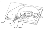
- In the art today, different methods are utilized to improve recording density of hard disk drives. FIG. 1 provides an illustration of a typical disk drive. The typical disk drive has a head gimbal assembly (HGA) configured to read from and write to a magnetic
hard disk 101. The HGA and the magnetichard disk 101 are mounted to thebase 102 of amain board 103. Thedisk 101 is rotated relative to thebase 102 by aspindle motor 104. The HGA typically includes anactuator arm 105 and aload beam 106. The HGA supports and positions a magnetic read/writeslider 107 above the magnetichard disk 101. The HGA is rotated relative to thebase 102 along the axis of abearing assembly 108. The HGA is rotated by a magnetic field generated between ayoke 109 and amagnetic block 110. A relay flexible printedcircuit 111 connects aboard unit 112 to the magnetic read/writeslider 107. Acover 113 protects the hard drive components as they operate. Often, the cover is attached by a set ofscrews 114. - FIG. 2 provides an illustration of a head actuator mechanism as configured in the prior art. The HGA, in this embodiment including an
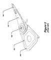
actuator arm 105 and aloadbeam 106, are coupled to an actuator driving mechanism. In one embodiment, more than one HGA are coupled to the actuator driving mechanism. The actuator driving mechanism can include adriving coil 201 attached to acoil holding frame 202. The magnetic field generated by theyoke 109 andmagnetic block 110 acts upon thedriving coil 201 causing thecoil holding frame 202, and by extension the HGA, to move. The HGA and actuator driving mechanism pivot around thebearing assembly 108. Aspacer 203 separates each HGA and actuator driving mechanism from the other HGA's and driving mechanisms on thebearing assembly 108. - FIG. 3 provides an illustration of the assembled head actuator mechanism. The
loadbeam 107 is coupled toactuator arm 108 to form the HGA. Thedriving coil 201 is coupled to thecoil holding frame 202 to form the actuator driving mechanism. The HGA is bonded to the actuator driving mechanism. The entire head actuator mechanism pivots on the bearing assembly. - Creating a single head actuator mechanism often results in damage to the head actuator mechanism during assembly. The driving coil becomes distorted, causing the head actuator mechanism not to move efficiently or correctly. Further, the closeness of the drive coil to the HGA can distort the positioning of the magnetic read/write head. A method is needed for manufacturing the head actuator mechanism without potentially causing damage to the drive coil.
- FIG. 1 provides an illustration of a typical disk drive.
- FIG. 2 provides an illustration of a head actuator mechanism as configured in the prior art.
- FIG. 3 provides an illustration of the assembled head actuator mechanism.
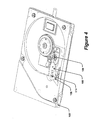
- FIG. 4 illustrates one embodiment of a top view of a hard disk drive as constructed in the present invention.
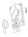
- FIG. 5 illustrates one embodiment of the actuator driving mechanism mounted on the underside of the base.
- FIGS. 6 a-b illustrate the assembly of the head actuator mechanism.
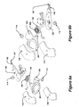
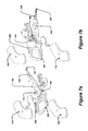
- FIGS. 7 a-b illustrate one embodiment of the assembled head actuator mechanism.
- FIGS. 8 a-b illustrate one embodiment of a cross section of the hard disk drive.
- A head actuator mechanism and a method of manufacture for that mechanism are disclosed. In one embodiment, the head actuator mechanism includes a head gimbal assembly coupled to the top support face of a bearing assembly and an actuator driving mechanism coupled to the opposite support face. In a further embodiment, the head gimbal assembly includes an actuator arm and a load beam, the actuator arm being mounted to the top support face. In a further embodiment, the actuator driving assembly includes a driving coil and a coil holder frame. The driving coil is positioned in a magnetic field created by a magnetic block and yoke. By separating the actuator driving mechanism from the head gimbal assembly, the driving coil is protected from damage that could be caused during assembly. Further, the assembly process is simplified.
- FIG. 4 illustrates one embodiment of a top view of a hard disk drive as constructed in the present invention. In one embodiment, the HGA includes a
load beam 106 and anactuator arm 105. The head gimbal assembly (HGA) is mounted on thebase 102 by coupling theactuator arm 105 to a top surface of thebearing assembly 108. In one embodiment, the HGA is mounted to the top surface of a bearing assembly using ascrew 114. - FIG. 5 illustrates one embodiment of the actuator driving mechanism mounted on the underside of the
base 102. In one embodiment, the actuator driving mechanism includes adriving coil 201 and acoil holding frame 202. While thedriving coil 201 is positioned underneath ayoke 109, amagnetic block 110 is positioned in thebase 102 underneath thedriving coil 201. - FIGS. 6 a-b illustrate the assembly of the head actuator mechanism. FIG. 6a illustrates a top view of the assembly. The HGA is mounted to the
support face 601 of thebearing assembly 108. In one embodiment, the HGA includes aloadbeam 106 coupled to anactuator arm 105. In one embodiment, theloadbeam 106 is coupled to theactuator arm 105 by laser welding. In a further embodiment, theactuator arm 105 is mounted to thetop support face 601 using ascrew 114. FIG. 6b illustrates a bottom view of the assembly. The actuator driving mechanism is mounted to theopposite support face 602 from the HGA. In one embodiment, the actuator driving mechanism includes a drivingcoil 201 coupled to acoil holding frame 202. In a further embodiment, thecoil holding frame 202 is mounted to theopposite support face 602 using ascrew 114. In one embodiment, the HGA and the actuator driving are assembled separately before being mounted to the bearingassembly 108. - FIGS. 7 a-b illustrate one embodiment of the assembled head actuator mechanism. FIG. 7a illustrates the top view and FIG. 7b illustrates the bottom view. The driving
coil 201 of the actuator driving mechanism is positioned between theyoke 109 andmagnetic block 110. In one embodiment, thecoil holding frame 202 is shaped to position the drivingcoil 201 on a plane with the head gimbal assembly. Theyoke 109 and themagnetic block 110 generate a magnetic field that acts upon the electric field created by the current running through the drivingcoil 201. The drivingcoil 201 is moved by the magnetic field, causing thecoil holding frame 202 to be moved. Thecoil holding frame 201 pivots along the axis of the bearingassembly 108. The torque generated on the bearingassembly 108 by the movement of thecoil holding frame 202 is passed to the HGA, causing the HGA to pivot in the same tangential direction. The HGA moves the magnetic read/write slider 107 in a radial direction on themagnetic storage disk 101. - FIG. 8 a illustrates in a planar view one embodiment of a cross section of the hard disk drive. FIG. 8b illustrates the same cross section in a perspective view. The driving
coil 201 is positioned between theyoke 109 and themagnetic block 110. In one embodiment, themagnetic block 110 is attached to thebase 102 and theyoke 109 is attached to a cover of thecoil motor 801. The HGA is mounted to thetop support face 601 of the bearingassembly 108. The actuator driving mechanism is mounted to theopposite support face 602 of the bearingassembly 108. In one embodiment, a coil motorcover seal layer 802 protects the actuator driving mechanism mounting. - Although several embodiments are specifically illustrated and described herein, it will be appreciated that modifications and variations of the present invention are covered by the above teachings and within the purview of the appended claims without departing from the spirit and intended scope of the invention.
Claims (8)
1-13. (Cancelled)
14. A method, comprising:
coupling a head gimbal assembly to a top support face of a pivot assembly to facilitate rotation around an axis; and
coupling an actuator driving mechanism to an opposite support face of the pivot assembly.
15. The method of claim 14 , further including:
coupling a load beam to the magnetic read/write slider head; and
coupling the load beam to the pivot assembly via an actuator arm.
16. The method of claim 15 , wherein the load beam is coupled to the actuator arm by laser welding.
17. The method of claim 14 , wherein the actuator driving mechanism includes:
a driving coil to be acted upon by an electromagnetic field; and
a holding frame to couple the driving coil to the bearing assembly.
18. The method of claim 17 , wherein the holding frame is shaped to position the driving coil on a plane with the head gimbal assembly.
19. The method of claim 17 , further comprising:
positioning a magnetic block beneath the driving coil; and
positioning a yoke above the driving coil.
20. The method of claim 14 , further including assembling the actuator driving mechanism and the head gimbal assembly as separate individual components.
Priority Applications (1)
| Application Number | Priority Date | Filing Date | Title |
|---|---|---|---|
| US10/894,513 US20040250412A1 (en) | 2002-09-04 | 2004-07-19 | Construction method and design for a magnetic head actuator mechanism |
Applications Claiming Priority (4)
| Application Number | Priority Date | Filing Date | Title |
|---|---|---|---|
| PCT/CN2002/000618 WO2004023486A1 (en) | 2002-09-04 | 2002-09-04 | A construction method and design for a magnetic head actuator mechanism |
| WOPCT/CN02/00618 | 2002-09-04 | ||
| US10/355,473 US6847507B2 (en) | 2002-09-04 | 2003-01-31 | Construction method and design for a magnetic head actuator mechanism |
| US10/894,513 US20040250412A1 (en) | 2002-09-04 | 2004-07-19 | Construction method and design for a magnetic head actuator mechanism |
Related Parent Applications (1)
| Application Number | Title | Priority Date | Filing Date |
|---|---|---|---|
| US10/355,473 Division US6847507B2 (en) | 2002-09-04 | 2003-01-31 | Construction method and design for a magnetic head actuator mechanism |
Publications (1)
| Publication Number | Publication Date |
|---|---|
| US20040250412A1 true US20040250412A1 (en) | 2004-12-16 |
Family
ID=31954562
Family Applications (2)
| Application Number | Title | Priority Date | Filing Date |
|---|---|---|---|
| US10/355,473 Expired - Fee Related US6847507B2 (en) | 2002-09-04 | 2003-01-31 | Construction method and design for a magnetic head actuator mechanism |
| US10/894,513 Abandoned US20040250412A1 (en) | 2002-09-04 | 2004-07-19 | Construction method and design for a magnetic head actuator mechanism |
Family Applications Before (1)
| Application Number | Title | Priority Date | Filing Date |
|---|---|---|---|
| US10/355,473 Expired - Fee Related US6847507B2 (en) | 2002-09-04 | 2003-01-31 | Construction method and design for a magnetic head actuator mechanism |
Country Status (3)
| Country | Link |
|---|---|
| US (2) | US6847507B2 (en) |
| CN (1) | CN1327439C (en) |
| WO (1) | WO2004023486A1 (en) |
Cited By (2)
| Publication number | Priority date | Publication date | Assignee | Title |
|---|---|---|---|---|
| US20070002496A1 (en) * | 2005-06-30 | 2007-01-04 | Seagate Technology Llc | Actuator coil support for enhanced performance |
| EP2031585A1 (en) | 2007-09-03 | 2009-03-04 | Samsung Electronics Co., Ltd. | Arm plate, head stack assembly comprising the same, and hard disk drive comprising the head stack assembly |
Families Citing this family (7)
| Publication number | Priority date | Publication date | Assignee | Title |
|---|---|---|---|---|
| EP1697983B1 (en) * | 2003-12-09 | 2012-06-13 | The Regents of The University of California | Highly efficient gallium nitride based light emitting diodes having surface roughening |
| CN100363983C (en) * | 2005-12-29 | 2008-01-23 | 深圳易拓科技有限公司 | Hard disk drive mounting method, magnetic block and clamp dedicated for the method |
| KR100826504B1 (en) * | 2006-07-10 | 2008-05-02 | 삼성전자주식회사 | Hard Disk Drive |
| US20090287120A1 (en) * | 2007-12-18 | 2009-11-19 | Searete Llc, A Limited Liability Corporation Of The State Of Delaware | Circulatory monitoring systems and methods |
| US8677607B2 (en) | 2008-03-07 | 2014-03-25 | Tdk Corporation | Method of manufacturing magnetoresistive element |
| US20090279211A1 (en) * | 2008-05-07 | 2009-11-12 | Sae Magnetics (Hk) Ltd. | Bearing apparatus for a hard disk drive |
| US9019657B1 (en) | 2013-03-13 | 2015-04-28 | Western Digital Technologies, Inc. | Coined VCM tab to limit cover deflection under pinch load |
Citations (8)
| Publication number | Priority date | Publication date | Assignee | Title |
|---|---|---|---|---|
| US4490635A (en) * | 1980-09-24 | 1984-12-25 | Quantum Corporation | Pure torque, limited displacement transducer |
| US5495375A (en) * | 1994-09-12 | 1996-02-27 | International Business Machines Corporation | Actuator arm assembly with self-locking arm |
| US5631786A (en) * | 1994-05-19 | 1997-05-20 | International Business Machines Corporation | Termination pad manipulator for a laminated suspension in a data storage system |
| US5631789A (en) * | 1994-06-24 | 1997-05-20 | Maxtor Corporation | Suspension clip ring mount |
| US5650896A (en) * | 1995-05-17 | 1997-07-22 | Quantum Corporation | Low cost plastic overmolded rotary voice coil actuator |
| US5691581A (en) * | 1995-01-06 | 1997-11-25 | Hitachi Metals, Ltd. | Arm assembly and voice coil motor |
| US5914836A (en) * | 1997-03-31 | 1999-06-22 | Seagate Technology, Inc. | Cantilevered support for the magnetic circuit of a disc drive voice coil motor |
| US6295183B1 (en) * | 1999-08-31 | 2001-09-25 | Magnecomp Corp. | Wireless disk drive suspension with optimized mechanical and electrical properties |
Family Cites Families (6)
| Publication number | Priority date | Publication date | Assignee | Title |
|---|---|---|---|---|
| JPH054302A (en) * | 1991-06-26 | 1993-01-14 | Kobe Steel Ltd | Steel sheet compounded with resin |
| EP0555969A1 (en) * | 1992-02-13 | 1993-08-18 | Seagate Technology International | Directly welded load beam flexure assembly |
| JP3344683B2 (en) * | 1995-06-07 | 2002-11-11 | インターナショナル・ビジネス・マシーンズ・コーポレーション | Actuator assembly and data storage system |
| JP3470568B2 (en) * | 1997-09-26 | 2003-11-25 | 富士通株式会社 | Information recording device having voice coil motor and cover thereof |
| US6577474B2 (en) * | 2000-02-09 | 2003-06-10 | Seagate Technology Llc | Integrated voice coil motor assembly for a disc drive |
| US6654208B2 (en) * | 2000-08-23 | 2003-11-25 | Seagate Technology Llc | Reduced inertia actuator pivot assembly |
-
2002
- 2002-09-04 CN CNB028295439A patent/CN1327439C/en not_active Expired - Fee Related
- 2002-09-04 WO PCT/CN2002/000618 patent/WO2004023486A1/en active Application Filing
-
2003
- 2003-01-31 US US10/355,473 patent/US6847507B2/en not_active Expired - Fee Related
-
2004
- 2004-07-19 US US10/894,513 patent/US20040250412A1/en not_active Abandoned
Patent Citations (8)
| Publication number | Priority date | Publication date | Assignee | Title |
|---|---|---|---|---|
| US4490635A (en) * | 1980-09-24 | 1984-12-25 | Quantum Corporation | Pure torque, limited displacement transducer |
| US5631786A (en) * | 1994-05-19 | 1997-05-20 | International Business Machines Corporation | Termination pad manipulator for a laminated suspension in a data storage system |
| US5631789A (en) * | 1994-06-24 | 1997-05-20 | Maxtor Corporation | Suspension clip ring mount |
| US5495375A (en) * | 1994-09-12 | 1996-02-27 | International Business Machines Corporation | Actuator arm assembly with self-locking arm |
| US5691581A (en) * | 1995-01-06 | 1997-11-25 | Hitachi Metals, Ltd. | Arm assembly and voice coil motor |
| US5650896A (en) * | 1995-05-17 | 1997-07-22 | Quantum Corporation | Low cost plastic overmolded rotary voice coil actuator |
| US5914836A (en) * | 1997-03-31 | 1999-06-22 | Seagate Technology, Inc. | Cantilevered support for the magnetic circuit of a disc drive voice coil motor |
| US6295183B1 (en) * | 1999-08-31 | 2001-09-25 | Magnecomp Corp. | Wireless disk drive suspension with optimized mechanical and electrical properties |
Cited By (3)
| Publication number | Priority date | Publication date | Assignee | Title |
|---|---|---|---|---|
| US20070002496A1 (en) * | 2005-06-30 | 2007-01-04 | Seagate Technology Llc | Actuator coil support for enhanced performance |
| EP2031585A1 (en) | 2007-09-03 | 2009-03-04 | Samsung Electronics Co., Ltd. | Arm plate, head stack assembly comprising the same, and hard disk drive comprising the head stack assembly |
| US20090059434A1 (en) * | 2007-09-03 | 2009-03-05 | Samsung Electronics Co., Ltd. | Arm blade, head stack assembly comprising the same, and hard disk drive comprising the head stack assembly |
Also Published As
| Publication number | Publication date |
|---|---|
| US20040042124A1 (en) | 2004-03-04 |
| US6847507B2 (en) | 2005-01-25 |
| CN1327439C (en) | 2007-07-18 |
| WO2004023486A1 (en) | 2004-03-18 |
| CN1689102A (en) | 2005-10-26 |
Similar Documents
| Publication | Publication Date | Title |
|---|---|---|
| US7092216B1 (en) | Disk drives and actuator assemblies having a pair of bonded voice coil supporting arms | |
| US7161769B1 (en) | Disk drive having an actuator arm assembly that includes stamped actuator arms | |
| US7593191B2 (en) | HGA having separate dimple element, disk drive unit with the same, and manufacturing method thereof | |
| US6765759B2 (en) | Resonance four piece suspension | |
| US20080024914A1 (en) | Collocated metal frame pzt micro-actuator with a lower stiffness suspension design | |
| JPH0478072A (en) | Disc device and manufacture thereof | |
| US5038240A (en) | Thin apparatus for etched on apparatus body recording medium with wiring pattern | |
| US20050268456A1 (en) | Method of manufacturing head actuator assembly and method of manufacturing disk device | |
| KR100773739B1 (en) | Head gimbal assembly and hard disk drive having the same | |
| US6847507B2 (en) | Construction method and design for a magnetic head actuator mechanism | |
| JPH07176181A (en) | Disk drive and its assembly method | |
| US8873202B2 (en) | Head gimbal assembly in which flexure swing is suppressed and disk device including the same | |
| US7054111B2 (en) | Disk drive actuator-pivot assembly with corrugated rings | |
| JP3375259B2 (en) | Magnetic disk drive | |
| US7551403B2 (en) | HSA with air turbulence preventing structure for HGA, disk drive unit with the same, and manufacturing method thereof | |
| US20050195530A1 (en) | Stacked actuator arm assembly with printed circuit card mount | |
| EP1522065B1 (en) | Head support mechanism, head drive device, and disk apparatus | |
| US20070274007A1 (en) | Air razor and disk limiter for a hard disk drive | |
| JP2002343071A (en) | Magnetic disk device | |
| US20080278849A1 (en) | Flow balancer for track misregistration improvement | |
| US20060187586A1 (en) | Method and apparatus for an improved magnetic head arm assembly | |
| US20040052002A1 (en) | Voice coil motor for a hard disk drive | |
| JP2001057040A (en) | Head suspension, head gimbals assembly and actuator | |
| JP3884169B2 (en) | Head actuator and magnetic disk device having the head actuator | |
| WO2004072974A1 (en) | Head suspension, information storage device, and lead |
Legal Events
| Date | Code | Title | Description |
|---|---|---|---|
| STCB | Information on status: application discontinuation |
Free format text: ABANDONED -- AFTER EXAMINER'S ANSWER OR BOARD OF APPEALS DECISION |