US20040066773A1 - Decision feedback channel estimation and pilot tracking for OFDM systems - Google Patents
Decision feedback channel estimation and pilot tracking for OFDM systems Download PDFInfo
- Publication number
- US20040066773A1 US20040066773A1 US10/263,415 US26341502A US2004066773A1 US 20040066773 A1 US20040066773 A1 US 20040066773A1 US 26341502 A US26341502 A US 26341502A US 2004066773 A1 US2004066773 A1 US 2004066773A1
- Authority
- US
- United States
- Prior art keywords
- symbol
- sub
- channels
- ceu
- data
- Prior art date
- Legal status (The legal status is an assumption and is not a legal conclusion. Google has not performed a legal analysis and makes no representation as to the accuracy of the status listed.)
- Granted
Links
Images


Classifications
-
- H—ELECTRICITY
- H04—ELECTRIC COMMUNICATION TECHNIQUE
- H04L—TRANSMISSION OF DIGITAL INFORMATION, e.g. TELEGRAPHIC COMMUNICATION
- H04L25/00—Baseband systems
- H04L25/02—Details ; arrangements for supplying electrical power along data transmission lines
- H04L25/0202—Channel estimation
- H04L25/022—Channel estimation of frequency response
-
- H—ELECTRICITY
- H04—ELECTRIC COMMUNICATION TECHNIQUE
- H04L—TRANSMISSION OF DIGITAL INFORMATION, e.g. TELEGRAPHIC COMMUNICATION
- H04L25/00—Baseband systems
- H04L25/02—Details ; arrangements for supplying electrical power along data transmission lines
- H04L25/03—Shaping networks in transmitter or receiver, e.g. adaptive shaping networks
- H04L25/03006—Arrangements for removing intersymbol interference
- H04L2025/03433—Arrangements for removing intersymbol interference characterised by equaliser structure
- H04L2025/03439—Fixed structures
- H04L2025/03522—Frequency domain
-
- H—ELECTRICITY
- H04—ELECTRIC COMMUNICATION TECHNIQUE
- H04L—TRANSMISSION OF DIGITAL INFORMATION, e.g. TELEGRAPHIC COMMUNICATION
- H04L25/00—Baseband systems
- H04L25/02—Details ; arrangements for supplying electrical power along data transmission lines
- H04L25/0202—Channel estimation
- H04L25/0224—Channel estimation using sounding signals
- H04L25/0228—Channel estimation using sounding signals with direct estimation from sounding signals
- H04L25/023—Channel estimation using sounding signals with direct estimation from sounding signals with extension to other symbols
- H04L25/0236—Channel estimation using sounding signals with direct estimation from sounding signals with extension to other symbols using estimation of the other symbols
-
- H—ELECTRICITY
- H04—ELECTRIC COMMUNICATION TECHNIQUE
- H04L—TRANSMISSION OF DIGITAL INFORMATION, e.g. TELEGRAPHIC COMMUNICATION
- H04L27/00—Modulated-carrier systems
- H04L27/26—Systems using multi-frequency codes
- H04L27/2601—Multicarrier modulation systems
- H04L27/2647—Arrangements specific to the receiver only
Definitions
- the present invention relates to an Orthogonal Frequency Division Multiplexing (OFDM) system, and in particular to improvements in channel estimation and pilot tracking in this OFDM system.
- OFDM Orthogonal Frequency Division Multiplexing
- Wireless systems frequently operate under challenging conditions. These conditions include the complexity of the environment in which a communication channel is desired and the mobility of one or more users using the channel in such an environment. For example, objects in the environment can reflect a transmitted wireless signal. This phenomenon is called a multipath condition. To address multipath and other conditions, a wireless system can employ various techniques. One such technique is Orthogonal Frequency Division Multiplexing (OFDM).
- OFDM Orthogonal Frequency Division Multiplexing
- a signal can be split into multiple narrowband channels (called sub-channels) at different frequencies.
- sub-channels For example, current 802.11a OFDM systems include 52 sub-channels.
- a transmitted signal could be represented by x ⁇ 26 . . . x ⁇ 1 , x 1 . . . x 26 , wherein both negative and positive side frequencies are included.
- each sub-channel carries a portion of the signal.
- Each sub-channel is “orthogonal” (i.e. independent) from every other sub-channel. Multipath conditions and noise can result in deterioration of this orthogonality.
- FIG. 1 illustrates a portion of a data packet 100 including a preamble 105 .
- preamble 105 includes 10 “short” identical known symbols 101 A- 101 J of length 16 (hereinafter shorts 101 ) concatenated to 2 “long” identical known symbols 102 A- 102 B of length 64 (hereinafter longs 102 ).
- shorts 101 10 “short” identical known symbols 101 A- 101 J of length 16
- longs 102 identical known symbols
- a symbol refers to any waveform in time (e.g. represented as voltage versus time).
- Longs 102 can be used to provide channel estimation. Specifically, because longs 102 are known, the receiver can use these symbols to provide rough channel estimations for a subsequent data symbol 103 in the data packet. In this manner, longs 102 can thereby increase the likelihood that the received data symbols can be correctly interpreted. Longs 102 are also called “training” symbols because they can “train” a frequency domain equalizer to learn about channel conditions.
- Shorts 101 can be used to determine any frequency offset between the oscillators in the receiver and transmitter. Additionally, shorts 101 can be used to provide an initial system time synchronization. System time synchronization can also be continuously tuned using the data symbols, as now described in further detail.
- the 802.11a standard provides that guard intervals (called GIs or mechanism cyclic prefixes) should be placed before longs and data.
- GIs guard intervals
- a double guard interval (GI2) is placed before long symbols 102 A- 102 B, thereby forming part of longs 102 .
- a regular guard interval (GI) is placed before data 103 A, thereby forming part of data symbol 103 .
- the double guard interval is twice as long as the regular guard interval.
- the guard intervals are derived from their associated symbols. For example, FIG. 2 illustrates simplified data 202 , which could be generated by 64 samples over time.
- a guard interval 201 essentially copies a last portion of data 202 and attaches it to the beginning of data 202 .
- the last 1 ⁇ 4 of the symbol is copied.
- a last portion of longs 102 can also be copied to form double guard interval GI2 (e.g. in the 802.11a standard, essentially the last half of long symbol 102 B).
- a difference between the frequency of the transmitter and receiver oscillators can adversely and significantly impact system performance. For example, if the receiver's clock is not aligned with the incoming data, then sampling of the received signal could be sub-optimal. For this reason, “pilots”, also known signals (e.g. ⁇ 1 and 1) defined by the 802.11a standard, are provided on 4 of the 52 orthogonal sub-channels to track and correct the difference between clocks.
- pilots also known signals (e.g. ⁇ 1 and 1) defined by the 802.11a standard, are provided on 4 of the 52 orthogonal sub-channels to track and correct the difference between clocks.
- FIG. 3 illustrates a data symbol 300 including a GI 301 and data 302 .
- the receiver's clock samples earlier in time than the incoming data, then instead of detecting the values indicated by 1 st sampling 303 , the values indicated by 2 nd sampling 304 could be detected.
- This de-synchronization can result in a phase ramp 400 in the frequency domain, as shown in FIG. 4.
- phase ramp 400 is negative when the receiver's clock samples earlier in time than the incoming data and positive when the receiver's clock samples later in time than the incoming data. Because of the continual “slide” in sampling (see FIG. 3), the slope of the phase can continue to rotate symbol by symbol.
- the signal when a signal is transmitted, the signal is modulated by the channel frequency, thereby improving its propagation properties in the channel.
- the modulation is based on the clock at the transmitter.
- the signal at the receiver, the signal must be demodulated. This demodulation can result in some residual phase, which can be represented by an offset 401 .
- the 4 pilots provided by the 802.11 standard attempt to track the phase slope and phase offset, thereby allowing the system to compensate for such slope and offset when necessary.
- decision feedback mechanisms can be provided to significantly improve channel estimation and pilot tracking in OFDM systems.
- the decision feedback mechanisms can use data symbols in the data packet to improve channel estimation as well as data sub-channels to improve pilot tracking.
- a method of refining channel estimations in an OFDM system includes analyzing two training symbols provided in a preamble of a data packet and analyzing multiple data symbols of the data packet.
- the number of multiple data symbols can be limited to reduce power consumption.
- the analyzing of multiple data symbols can include storing a received data symbol.
- the received data symbol can also be decoded using, for example a Viterbi decoder.
- a transmitted signal corresponding to the received data symbol can be reconstructed from the decoded symbol.
- the stored received data symbol can then be divided by the reconstructed transmitted signal.
- Channel estimations can be refined based on the results of that division.
- a channel estimation unit can generate an initial channel estimate based on analyzing of the two training symbols.
- the CEU can refine that initial channel estimate based on a subsequent data symbol. Recursive refinements of the channel estimate can be made using subsequent data symbols.
- a weighting factor can be provided for each analyzed data symbol.
- the step of dividing can include determining the latencies for decoding the data symbols following a SIGNAL symbol.
- An OFDM receiver in accordance with the invention can include a channel estimator unit (CEU), a frequency domain equalizer (FEQ) for detecting a received signal from the transmitter using the receiving channel estimations from the CEU.
- CEU channel estimator unit
- FEQ frequency domain equalizer
- a decision feedback mechanism in the OFDM receiver advantageously allows refinement of the channel estimations.
- the decision feedback mechanism can include a decoder for decoding a received data symbol as well as an encoder for reconstructing a transmitted signal that corresponds to the received data symbol.
- the decision feedback mechanism can further include storage for storing the received data symbol and a dividing unit for dividing the stored received data symbol by the reconstructed transmitted signal. The dividing unit provides its result to the CEU for channel estimation refinement.
- the storage can include means for providing a latency corresponding to a decoding of each symbol performed by the decoder.
- the CEU can include means for providing a weighting factor based on a number of results received from the dividing unit.
- the CEU can include means for limiting channel estimation based on a number of results received from the dividing unit.
- a method of improving pilot tracking in an OFDM system can include using a first subset of sub-channels in the OFDM system to provide a first accuracy of pilot tracking and using a second subset of sub-channels in the OFDM system to provide a second accuracy of pilot tracking.
- the first subset of sub-channels includes only pilot sub-channels whereas the second subset of sub-channels includes data sub-channels.
- Using the second subset of sub-channels can include applying a phase estimation for a previous symbol to a current received symbol.
- a hard decision can be generated based on the step of applying.
- generating the hard decision can include a mapping function.
- the current received symbol can be divided by the hard decision to generate a phase.
- This phase can be provided to a channel estimation unit (CEU) in the OFDM system.
- CEU channel estimation unit
- Using the second subset of sub-channels can further include selecting data sub-channels based on signal-to-noise ratios. For example, the number of selected data sub-channels could be limited to N. The data sub-channels could then be divided into N groups. The data sub-channel having the maximum power gain in each of the N groups could be selected.
- an OFDM receiver can include a channel estimation unit (CEU), a frequency domain equalizer (FEQ) for receiving phase estimations from the CEU as well as a received symbol from the transmitter, and a decision feedback mechanism coupled to the FEQ and the CEU.
- the decision feedback mechanism advantageously allows refinement of the phase estimations.
- the decision feedback mechanism can include means for calculating a hard decision and means for dividing a current received symbol by the hard decision, thereby generating a new phase for input to the CEU.
- the OFDM receiver can further include means for selecting sub-channels having at least a predetermined signal-to-noise ratio.
- the decision feedback mechanism uses only the selected sub-channels for refining the phase estimations.
- FIG. 1 illustrates a portion of a data packet including a preamble and a data symbol.
- FIG. 2 illustrates a simplified data pattern with a guard interval attached to the beginning of the data.
- FIG. 3 illustrates the effect of non-synchronized clocks for a transmitter and a receiver on the sampling of an exemplary data symbol.
- FIG. 4 illustrates a phase ramp and phase offset in the frequency domain caused by the de-synchronization shown in FIG. 3.
- the phase ramp is negative when the sampling time is earlier than the incoming data and positive when the sampling time is later than the incoming data.
- FIG. 5 illustrates the vector relationship between the transmitted symbol, the channel response, and the received symbol.
- FIG. 6 illustrates a block diagram of an OFDM receiver including decision feedback mechanisms for channel estimation and pilot tracking.
- FIG. 7 illustrates a flow chart for providing decision feedback channel estimation.
- FIG. 8 illustrates a flow chart for providing decision feedback channel pilot tracking.
- FIG. 9 illustrates a graph representing simulated results from using no decision feedback mechanisms, decision feedback channel estimation, decision feedback pilot tracking, and combined decision feedback channel estimation and pilot tracking at a data rate of 54 Mbps.
- FIG. 10 illustrates a graph representing simulated results from using no decision feedback mechanisms, decision feedback channel estimation, decision feedback pilot tracking, and combined decision feedback channel estimation and pilot tracking at a data rate of 6 Mbps.
- FIG. 11 illustrates a graph that shows the simulated impact of the number of data symbols used for decision feedback channel estimation on system performance.
- Channel estimation determines a response of a transmission medium, thereby facilitating the recovery of the transmitted symbol from its associated received symbol.
- a common model for channel response is a tap delay line, wherein the channel is represented by a series of taps, each tap having a certain delay.
- a symbol could be sampled at each tap, thereby determining its amplitude at that tap.
- this sampling can be represented as a convolution in a vector format, as shown in FIG. 5. Specifically, in FIG. 5, 64 samples are represented in vectors, i.e. received symbol 501 as well as transmitted symbol 503 .
- Channel response 502 which is a convolution, transforms transmitted symbol 503 into received symbol 501 .
- channel response 502 can be converted into a diagonal matrix by applying a Fast Fourier Transform (FFT) to received symbol 501 and transmitted symbol 503 .
- FFT Fast Fourier Transform
- orthogonal scalar channels i.e. a frequency spectrum
- OFDM orthogonal scalar channels
- n i,k is the additive white Gaussian noise in the i-th sub-channel for the k-th training symbol.
- ⁇ H i is the channel estimation error due to noise.
- Equation (4) data detection is subject to errors caused by channel estimation error and noise.
- ⁇ i (1 ⁇ p i,k ) ⁇ i +p i,k ⁇ i,k (6)
- the clock rate at the receiver and at the transmitter may be slightly different due to the frequency offset between the local oscillator (i.e. the oscillator at the receiver) and the oscillator at the transmitter.
- Frequency offset can cause an OFDM system to lose its orthogonality. Therefore, the offset is usually estimated and compensated for in the baseband signal processing. Residual frequency offset exists if the estimation is not perfect.
- the effective channel gain of the i-th sub-carrier for the k-th OFDM symbol can be represented as:
- H i,k H i ⁇ e j( ⁇ f i + ⁇ k ) (7)
- H i is the initial channel gain
- ⁇ k and ⁇ k are the phase slope and offset of the k-th symbol
- f i is the sub-carrier frequency.
- the slope ⁇ k and offset ⁇ k need to be estimated and tracked. This is realized by transmitting known signals, i.e. the pilots, on a few pre-selected sub-carriers of each OFDM symbol.
- s i,k be the pilot signal on the i-th sub-carrier of the k-th symbol, where i ⁇ I,I being the set of the sub-carrier indices of the pilots.
- ⁇ i,k be the phase of y i,k /s i,k . Then:
- ⁇ I ⁇ is the number of pilots. If ⁇ k f t + ⁇ k exceeds the range of ( ⁇ , ⁇ ), then a differential method based on the difference between every two consecutive symbols can replace the direct method.
- pilot tracking is subject to phase estimation errors due to noise, especially if one or more of the pilots are located in a null of the channel frequency response. Having more pilots will improve the tracking capability, but the transmission efficiency will be reduced.
- a decision feedback pilot tracking mechanism can use selected data sub-channels to enhance pilot tracking performance.
- FIG. 6 illustrates a block diagram of an OFDM receiver 600 including decision feedback mechanisms for channel estimation and pilot tracking. These mechanisms significantly enhance the performance of a standard data detection path, which includes a channel estimation unit (CEU) 602 , a frequency domain equalizer (FEQ) 603 , and a Viterbi decoder (DEC) 604 .
- CEU channel estimation unit
- FEQ frequency domain equalizer
- DEC Viterbi decoder
- the output of FFT 601 represents a received symbol (typically encoded) from a transmitter (not shown). After this received symbol is modified based on channel conditions and decoded, it can be provided to other components 612 for analysis/use.
- FIGS. 7 and 8 illustrate flow charts for providing decision feedback channel estimation and pilot tracking, respectively.
- Providing channel estimation 700 in accordance with the invention can include storing a received data symbol in step 701 .
- frequency domain equalization can be performed based on a previous channel estimation.
- Step 702 can further include decoding the result of frequency domain equalization.
- the decoded symbol can be encoded in step 703 to reconstruct the transmitted symbol.
- the stored (i.e. the received) symbol can be divided by the reconstructed symbol to generate a new channel estimation.
- the new channel estimation can be combined with the old channel estimation(s) to generate an improved channel estimation.
- the value provided by FFT 601 (i.e. symbol y i,k ) could be stored in a storage unit 607 .
- the size of storage unit 607 could be based on the latency of Viterbi decoder 604 .
- the 802.11a standard implements convolutional codes with rates of 1/2, 2/3, and 3/4.
- the first data symbol in each data packet is a SIGNAL symbol, which indicates the rate and length of the data packet.
- the SIGNAL symbol needs to be decoded before the receiver can start detecting the rest of the packet. Therefore the latency of the Viterbi decoder for the SIGNAL symbol is one OFDM symbol.
- the latency of the normal data symbols can range from 3 to 12 symbols for a typical traceback length (i.e. longer for lower data rates). In general, if the latency is L, then the symbol X i is not available for decision feedback channel estimation until at symbol time i+L.
- An FEQ 603 can be used to perform the frequency domain equalization of step 702 (i.e. compute the symbol X i using Equation 4). FEQ 603 can perform this equalization based on a previous channel estimation computed by CEU 602 (see Equations 5 and 6). Viterbi decoder 604 can decode the result of frequency domain equalization provided by FEQ 603 . An encoder 605 can then reconstruct the transmitted symbol in step 703 . A division unit 606 can be used to divide the reconstructed symbol by the stored (i.e. the received) symbol to generate a new channel estimation. CEU 602 can combine the new channel estimation with the old channel estimation(s) in step 705 to generate an improved channel estimation.
- the combination of channel estimations can be weighted to provide more accurate results.
- CEU 602 can deactivate the decision feedback channel estimation after a certain number of data symbols. In another embodiment, CEU 602 can perform the decision feedback channel estimation once every several data symbols, thereby also reducing power consumption.
- phase of the channel estimation from data symbols can rotate continuously.
- phase of ⁇ i,k is adjusted to a reference phase (i.e. an initial channel estimation) using the phase information obtained from pilot tracking (described in further detail below) before the combining in Equation (6).
- Providing pilot tracking 800 in accordance with the invention can include selecting a subset of the sub-channels in step 801 for the pilot tracking calculations. Specifically, to ensure reliable phase computation for the decision feedback pilot tracking, only sub-channels with good signal-to-noise ratios are selected. In one embodiment, sub-channels that have a power gain exceeding 1/4 of the maximum power gain or 1/2 of the mean power gain can be selected for pilot tracking.
- a hard limit can be set on the number of data sub-channels used for pilot tracking. For example, if the limit is X data sub-channels, then the data sub-channels can be divided into X groups, and the data sub-channel with the maximum power gain in each group can be selected. At this point, the power threshold can be applied to the selected sub-channels, e.g. any sub-channel below the threshold can be discarded. In another embodiment, a fixed set of data sub-channels can be pre-selected for decision feedback pilot tracking. In this embodiment, the power threshold can be applied to identify the sub-channels that exceed the designated power gain.
- phase information i.e. slope and offset
- frequency domain equalization can be performed on the current received data symbol.
- hard decisions i.e. phase slope and phase offset
- the current received data symbol can be divided by the hard decisions, thereby generating new phase information for the selected sub-channels. This new phase information can be provided to a channel estimation unit in step 805 to improve pilot tracking.
- CEU 602 can select the appropriate subset of the sub-channels for pilot tracking calculations.
- Delay 608 can be used to ensure that an FEQ 609 applies the channel estimation for the previous data symbol to the selected sub-channels of the current received data symbol, i.e. the symbol provided by FFT 601 , in step 802 .
- a hard decision device 610 implements Equations 9-12 in step 803 to output the phase slope and phase offset.
- a dividing device 611 can be used in step 804 to divide the current received data symbol by the hard decisions. The output of dividing device 611 , i.e. the new phase information, can be provided to CEU 602 in step 805 to further refine pilot tracing in OFDM receiver 600 .
- FIG. 9 illustrates a graph 900 representing results from using no decision feedback mechanisms (data points 901 ), decision feedback channel estimation (data points 902 ), decision feedback pilot tracking (data points 903 ), and combined decision feedback channel estimation and pilot tracking (data points 904 ).
- data points 901 decision feedback channel estimation
- data points 902 decision feedback pilot tracking
- data points 904 combined decision feedback channel estimation and pilot tracking
- SNR signal-to-noise ratio
- the channel was assumed to be constant during the transmission of each packet, but could be different for different packets.
- the length of the packets was assumed to be 1000 bytes.
- FIG. 9 indicates that both decision feedback channel estimation and decision feedback pilot tracking improve system performance.
- the packet error rate (PER) for either decision feedback mechanism is less than the PER without decision feedback.
- a total gain of approximately 7 dB can be achieved at 30% PER by combining decision feedback channel estimation and pilot tracking.
- FIG. 10 illustrates a graph 1000 representing results from using no decision feedback mechanisms (data points 1001 ), decision feedback channel estimation (data points 1002 ), decision feedback pilot tracking (data points 1003 ), and combined decision feedback channel estimation and pilot tracking (data points 1004 ).
- data points 1001 decision feedback channel estimation
- data points 1002 decision feedback pilot tracking
- data points 1004 combined decision feedback channel estimation and pilot tracking
- simulations were performed assuming a data rate of 6 Mbps with a delay spread of 200 ns.
- the SNR in FIG. 10 is approximately 14.7 plus the si margin (dB).
- the channel and packet lengths assumptions are the same as for FIG. 9.
- FIG. 10 indicates that less gain may be obtained from decision feedback channel estimation because a 6 Mbps system uses BPSK, which is less sensitive to channel estimation error. (54 Mbps uses 64 QAM.) However, decision feedback pilot tracking still yields significant gains with about 4 dB at PER of 10%.
- FIG. 11 illustrates a graph 1100 that shows the simulated impact of the number of data symbols used for decision feedback channel estimation on system performance.
- the performance of four different channel estimation setups is compared. Specifically, graph 1100 compares no decision feedback (data points 1101 ), decision feedback using only the SIGNAL symbol (data points 1102 ), decision feedback using 5 data symbols (data points 1103 ), and decision feedback using all the data symbols (data points 1104 ). In this simulation, decision feedback pilot tracking is used in all cases.
- a significant portion of the gain of decision feedback channel estimation is achieved from the SIGNAL symbol. Additional performance improvement can be achieved by using a limited number of data symbols, e.g. 4-12 data symbols. Of importance, the performance achieved by using 5 data symbols or using all data symbols is substantially the same.
Abstract
Description
- 1. Field of the Invention
- The present invention relates to an Orthogonal Frequency Division Multiplexing (OFDM) system, and in particular to improvements in channel estimation and pilot tracking in this OFDM system.
- 2. Description of the Related Art
- Wireless systems frequently operate under challenging conditions. These conditions include the complexity of the environment in which a communication channel is desired and the mobility of one or more users using the channel in such an environment. For example, objects in the environment can reflect a transmitted wireless signal. This phenomenon is called a multipath condition. To address multipath and other conditions, a wireless system can employ various techniques. One such technique is Orthogonal Frequency Division Multiplexing (OFDM).
- In an OFDM system, a signal can be split into multiple narrowband channels (called sub-channels) at different frequencies. For example, current 802.11a OFDM systems include 52 sub-channels. Thus, a transmitted signal could be represented by x −26 . . . x−1, x1 . . . x26, wherein both negative and positive side frequencies are included. In this configuration, each sub-channel carries a portion of the signal. Each sub-channel is “orthogonal” (i.e. independent) from every other sub-channel. Multipath conditions and noise can result in deterioration of this orthogonality.
- In an attempt to restore orthogonality, the 1999 IEEE 802.11a standard provides that a transmitted data packet includes a preamble, which precedes the actual data. FIG. 1 illustrates a portion of a
data packet 100 including apreamble 105. As defined in the 802.11a standard,preamble 105 includes 10 “short” identical known symbols 101A-101J of length 16 (hereinafter shorts 101) concatenated to 2 “long” identical knownsymbols 102A-102B of length 64 (hereinafter longs 102). Note that a symbol refers to any waveform in time (e.g. represented as voltage versus time). - Longs 102 can be used to provide channel estimation. Specifically, because longs 102 are known, the receiver can use these symbols to provide rough channel estimations for a
subsequent data symbol 103 in the data packet. In this manner, longs 102 can thereby increase the likelihood that the received data symbols can be correctly interpreted. Longs 102 are also called “training” symbols because they can “train” a frequency domain equalizer to learn about channel conditions. -
Shorts 101 can be used to determine any frequency offset between the oscillators in the receiver and transmitter. Additionally,shorts 101 can be used to provide an initial system time synchronization. System time synchronization can also be continuously tuned using the data symbols, as now described in further detail. - The 802.11a standard provides that guard intervals (called GIs or mechanism cyclic prefixes) should be placed before longs and data. Specifically, a double guard interval (GI2) is placed before
long symbols 102A-102B, thereby forming part of longs 102. In contrast, a regular guard interval (GI) is placed beforedata 103A, thereby forming part ofdata symbol 103. The double guard interval, as the name implies, is twice as long as the regular guard interval. In accordance with the 802.11a standard, the guard intervals are derived from their associated symbols. For example, FIG. 2 illustratessimplified data 202, which could be generated by 64 samples over time. Aguard interval 201 essentially copies a last portion ofdata 202 and attaches it to the beginning ofdata 202. For example, in the 802.11a standard, the last ¼ of the symbol is copied. A last portion oflongs 102 can also be copied to form double guard interval GI2 (e.g. in the 802.11a standard, essentially the last half oflong symbol 102B). - A difference between the frequency of the transmitter and receiver oscillators can adversely and significantly impact system performance. For example, if the receiver's clock is not aligned with the incoming data, then sampling of the received signal could be sub-optimal. For this reason, “pilots”, also known signals (e.g. −1 and 1) defined by the 802.11a standard, are provided on 4 of the 52 orthogonal sub-channels to track and correct the difference between clocks.
- For example, FIG. 3 illustrates a
data symbol 300 including aGI 301 anddata 302. If the receiver's clock samples earlier in time than the incoming data, then instead of detecting the values indicated by 1stsampling 303, the values indicated by 2ndsampling 304 could be detected. This de-synchronization can result in aphase ramp 400 in the frequency domain, as shown in FIG. 4. Note thatphase ramp 400 is negative when the receiver's clock samples earlier in time than the incoming data and positive when the receiver's clock samples later in time than the incoming data. Because of the continual “slide” in sampling (see FIG. 3), the slope of the phase can continue to rotate symbol by symbol. - Moreover, when a signal is transmitted, the signal is modulated by the channel frequency, thereby improving its propagation properties in the channel. The modulation is based on the clock at the transmitter. Thus, at the receiver, the signal must be demodulated. This demodulation can result in some residual phase, which can be represented by an
offset 401. The 4 pilots provided by the 802.11 standard attempt to track the phase slope and phase offset, thereby allowing the system to compensate for such slope and offset when necessary. - Unfortunately, sending just the two long symbols can be insufficient for accurate channel estimation, particularly when noise is present. Moreover, using four sub-channels can also be insufficient to compensate for phase slope and offset. Therefore, a need arises for a system and method for improving channel estimation and pilot tracking.
- Current OFDM systems use a limited number of symbols and/or sub-channels to provide approximations for channel estimations and pilot tracking, i.e. phase estimations. However, noise and other imperfections can cause errors in both of these estimations, thereby degrading system performance. Advantageously, decision feedback mechanisms can be provided to significantly improve channel estimation and pilot tracking in OFDM systems. The decision feedback mechanisms can use data symbols in the data packet to improve channel estimation as well as data sub-channels to improve pilot tracking.
- In accordance with one feature of the invention, a method of refining channel estimations in an OFDM system includes analyzing two training symbols provided in a preamble of a data packet and analyzing multiple data symbols of the data packet. In one embodiment, the number of multiple data symbols can be limited to reduce power consumption. The analyzing of multiple data symbols can include storing a received data symbol. The received data symbol can also be decoded using, for example a Viterbi decoder.
- At this point, a transmitted signal corresponding to the received data symbol can be reconstructed from the decoded symbol. The stored received data symbol can then be divided by the reconstructed transmitted signal. Channel estimations can be refined based on the results of that division.
- Specifically, in accordance with one feature of the invention, a channel estimation unit (CEU) can generate an initial channel estimate based on analyzing of the two training symbols. The CEU can refine that initial channel estimate based on a subsequent data symbol. Recursive refinements of the channel estimate can be made using subsequent data symbols. In one embodiment, a weighting factor can be provided for each analyzed data symbol.
- To ensure the step of dividing is accurately performed, certain latencies can be considered. For example, the first data symbol in each packet includes a SIGNAL symbol, which includes the rate and packet length of the packet. Therefore, the step of dividing can include determining the latencies for decoding the data symbols following a SIGNAL symbol.
- An OFDM receiver in accordance with the invention can include a channel estimator unit (CEU), a frequency domain equalizer (FEQ) for detecting a received signal from the transmitter using the receiving channel estimations from the CEU. A decision feedback mechanism in the OFDM receiver advantageously allows refinement of the channel estimations.
- The decision feedback mechanism can include a decoder for decoding a received data symbol as well as an encoder for reconstructing a transmitted signal that corresponds to the received data symbol. The decision feedback mechanism can further include storage for storing the received data symbol and a dividing unit for dividing the stored received data symbol by the reconstructed transmitted signal. The dividing unit provides its result to the CEU for channel estimation refinement.
- In one embodiment, the storage can include means for providing a latency corresponding to a decoding of each symbol performed by the decoder. In another embodiment, the CEU can include means for providing a weighting factor based on a number of results received from the dividing unit. In yet another embodiment, the CEU can include means for limiting channel estimation based on a number of results received from the dividing unit.
- In accordance with another feature of the invention, a method of improving pilot tracking in an OFDM system is provided. The method can include using a first subset of sub-channels in the OFDM system to provide a first accuracy of pilot tracking and using a second subset of sub-channels in the OFDM system to provide a second accuracy of pilot tracking. Of importance, the first subset of sub-channels includes only pilot sub-channels whereas the second subset of sub-channels includes data sub-channels.
- Using the second subset of sub-channels can include applying a phase estimation for a previous symbol to a current received symbol. A hard decision can be generated based on the step of applying. In one embodiment, generating the hard decision can include a mapping function. At this point, the current received symbol can be divided by the hard decision to generate a phase. This phase can be provided to a channel estimation unit (CEU) in the OFDM system.
- Using the second subset of sub-channels can further include selecting data sub-channels based on signal-to-noise ratios. For example, the number of selected data sub-channels could be limited to N. The data sub-channels could then be divided into N groups. The data sub-channel having the maximum power gain in each of the N groups could be selected.
- In accordance with another feature of the invention, an OFDM receiver can include a channel estimation unit (CEU), a frequency domain equalizer (FEQ) for receiving phase estimations from the CEU as well as a received symbol from the transmitter, and a decision feedback mechanism coupled to the FEQ and the CEU. The decision feedback mechanism advantageously allows refinement of the phase estimations. The decision feedback mechanism can include means for calculating a hard decision and means for dividing a current received symbol by the hard decision, thereby generating a new phase for input to the CEU.
- The OFDM receiver can further include means for selecting sub-channels having at least a predetermined signal-to-noise ratio. In this configuration, the decision feedback mechanism uses only the selected sub-channels for refining the phase estimations.
- FIG. 1 illustrates a portion of a data packet including a preamble and a data symbol.
- FIG. 2 illustrates a simplified data pattern with a guard interval attached to the beginning of the data.
- FIG. 3 illustrates the effect of non-synchronized clocks for a transmitter and a receiver on the sampling of an exemplary data symbol.
- FIG. 4 illustrates a phase ramp and phase offset in the frequency domain caused by the de-synchronization shown in FIG. 3. The phase ramp is negative when the sampling time is earlier than the incoming data and positive when the sampling time is later than the incoming data.
- FIG. 5 illustrates the vector relationship between the transmitted symbol, the channel response, and the received symbol.
- FIG. 6 illustrates a block diagram of an OFDM receiver including decision feedback mechanisms for channel estimation and pilot tracking.
- FIG. 7 illustrates a flow chart for providing decision feedback channel estimation.
- FIG. 8 illustrates a flow chart for providing decision feedback channel pilot tracking.
- FIG. 9 illustrates a graph representing simulated results from using no decision feedback mechanisms, decision feedback channel estimation, decision feedback pilot tracking, and combined decision feedback channel estimation and pilot tracking at a data rate of 54 Mbps.
- FIG. 10 illustrates a graph representing simulated results from using no decision feedback mechanisms, decision feedback channel estimation, decision feedback pilot tracking, and combined decision feedback channel estimation and pilot tracking at a data rate of 6 Mbps.
- FIG. 11 illustrates a graph that shows the simulated impact of the number of data symbols used for decision feedback channel estimation on system performance.
- System Overview
- Current OFDM systems use a limited number of symbols and/or sub-channels to provide approximations for channel estimations and pilot tracking, i.e. phase estimations. Unfortunately, noise and other imperfections in the OFDM systems can cause errors in these estimations, thereby degrading system performance. Advantageously, decision feedback mechanisms can be provided to significantly improve channel estimation and pilot tracking in OFDM systems. As described below, the decision feedback mechanisms can use data symbols in the data packet to improve channel estimation as well as data sub-channels to improve pilot tracking.
- Decision Feedback Channel Estimation Computation
- Channel estimation determines a response of a transmission medium, thereby facilitating the recovery of the transmitted symbol from its associated received symbol. A common model for channel response is a tap delay line, wherein the channel is represented by a series of taps, each tap having a certain delay. In this model, a symbol could be sampled at each tap, thereby determining its amplitude at that tap. Mathematically, this sampling can be represented as a convolution in a vector format, as shown in FIG. 5. Specifically, in FIG. 5, 64 samples are represented in vectors, i.e. received
symbol 501 as well as transmittedsymbol 503.Channel response 502, which is a convolution, transforms transmittedsymbol 503 into receivedsymbol 501. - Of importance,
channel response 502 can be converted into a diagonal matrix by applying a Fast Fourier Transform (FFT) to receivedsymbol 501 and transmittedsymbol 503. In this manner, instead of multiple taps with different delays (i.e. a time domain function), orthogonal scalar channels (i.e. a frequency spectrum) can be analyzed. Various aspects of an OFDM system can then be computed. - For example, consider an OFDM system with N sub-channels. If H i is the complex gain of the i-th sub-channel, then 1≦i≦N. Assume the channel remains constant during the duration of the data transmission. Let si be the data on the i-th sub-channel of the training symbol. If the same training symbol is transmitted twice, then the received signal is (k=1,2):
- y i,k =H i s i +n i,k (1)
- where n i,k is the additive white Gaussian noise in the i-th sub-channel for the k-th training symbol. The channel estimate based on the two training symbols can be obtained by:

- where ΔH i is the channel estimation error due to noise.
- If x i,k is the signal on the i-th sub-carrier for the k-th OFDM data symbol, then the received signal is:
- y i,k =H ixi,k +n i,k (3)
- and the signal can be detected as:

- from Equations (2) and (3). As indicated in Equation (4), data detection is subject to errors caused by channel estimation error and noise.
- Error correction codes, such as convolutional codes, can be used to correct the data errors. For example, let {tilde over (x)} i,k be the signal reconstructed from the decoded data symbols that corresponds to xi,k. If the signal is decoded correctly, then {tilde over (x)}i,k=xi,k. xi,k can be used to obtain an additional estimate of the channel:

- which can be combined with the current channel estimate to reduce the noise variance:
- Ĥ i=(1−p i,k)Ĥ i +p i,k Ĥ i,k (6)
- where 0≦p i,k≦1 is a weighting factor for the new channel estimate. This can be implemented iteratively for all the data symbols, k=1,2, . . . As described in further detail below, the weighting factor pi,k can decrease with the symbol index k. For amplitude modulations, pi,k can decrease with |{tilde over (x)}i,k| for better noise reduction.
- Note that the above channel estimation algorithm can cause error propagation in the case of a decoding error. However, a common performance measure for broadband wireless data systems is the packet error rate. If a decoding error occurs, then the packet is already in error. Therefore, error propagation does not increase the packet error rate and, logically, will not affect system performance.
- Decision Feedback Pilot Tracking Computation
- As described above, the clock rate at the receiver and at the transmitter may be slightly different due to the frequency offset between the local oscillator (i.e. the oscillator at the receiver) and the oscillator at the transmitter. Frequency offset can cause an OFDM system to lose its orthogonality. Therefore, the offset is usually estimated and compensated for in the baseband signal processing. Residual frequency offset exists if the estimation is not perfect.
- The effective channel gain of the i-th sub-carrier for the k-th OFDM symbol can be represented as:
- H i,k =H i ·e j(β f i +θ k ) (7)
- where H i is the initial channel gain, βk and θk are the phase slope and offset of the k-th symbol, and fi is the sub-carrier frequency. With frequency offset estimation and compensation, θk only depends on the residual frequency offset while βk depends on the frequency offset.
- In order to detect the signal in the presence of frequency offset, the slope β k and offset θk need to be estimated and tracked. This is realized by transmitting known signals, i.e. the pilots, on a few pre-selected sub-carriers of each OFDM symbol. Let si,k be the pilot signal on the i-th sub-carrier of the k-th symbol, where iεI,I being the set of the sub-carrier indices of the pilots. Let αi,k be the phase of yi,k/si,k. Then:
- αi,k=βk f i+θk(mod 2π) (8)
- β k and θk can be found by solving a traditional Least Square (LS) problem:
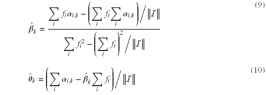
- where ∥I∥ is the number of pilots. If β kft+θk exceeds the range of (−π, π), then a differential method based on the difference between every two consecutive symbols can replace the direct method.
- Of importance, pilot tracking is subject to phase estimation errors due to noise, especially if one or more of the pilots are located in a null of the channel frequency response. Having more pilots will improve the tracking capability, but the transmission efficiency will be reduced.
- In accordance with one feature of the invention, a decision feedback pilot tracking mechanism can use selected data sub-channels to enhance pilot tracking performance. First, hard decisions are obtained using the current symbol and the phase estimate of the previous symbol:

- where 9(·) is a hard decision mapping function. Then, the phase of the data sub-carriers is calculated by taking the angle of y i,k/{overscore (x)}i,k. The results are used together with the phase of the pilots to compute βk and θk. As a result, the effective number of pilots is increased and the performance of pilot tracking is improved.
- Because the slope β k depends on the timing offset,
- θk=2πδ·kT (12)
- where δ is the ppm frequency offset of the timing clock, and T is the OFDM symbol period, an alternative method is to compute {circumflex over (β)} k based on the frequency offset estimation using Equation (12). The offset {circumflex over (θ)}k can still be computed using Equation (10). Note that for this computation the symbol timing clock is locked to the carrier frequency at both the transmitter and the receiver, which is mandatory in the 802.11a standard.
- Exemplary Implementations For Decision Feedback Mechanisms
- FIG. 6 illustrates a block diagram of an
OFDM receiver 600 including decision feedback mechanisms for channel estimation and pilot tracking. These mechanisms significantly enhance the performance of a standard data detection path, which includes a channel estimation unit (CEU) 602, a frequency domain equalizer (FEQ) 603, and a Viterbi decoder (DEC) 604. Note that the output ofFFT 601 represents a received symbol (typically encoded) from a transmitter (not shown). After this received symbol is modified based on channel conditions and decoded, it can be provided toother components 612 for analysis/use. - FIGS. 7 and 8 illustrate flow charts for providing decision feedback channel estimation and pilot tracking, respectively. Providing
channel estimation 700 in accordance with the invention (FIG. 7) can include storing a received data symbol instep 701. Instep 702, frequency domain equalization can be performed based on a previous channel estimation. Step 702 can further include decoding the result of frequency domain equalization. - The decoded symbol can be encoded in
step 703 to reconstruct the transmitted symbol. Instep 704, the stored (i.e. the received) symbol can be divided by the reconstructed symbol to generate a new channel estimation. Instep 705, the new channel estimation can be combined with the old channel estimation(s) to generate an improved channel estimation. - Referring back to FIG. 6, to implement
step 701, the value provided by FFT 601 (i.e. symbol yi,k) could be stored in astorage unit 607. In one embodiment, the size ofstorage unit 607 could be based on the latency ofViterbi decoder 604. Specifically, the 802.11a standard implements convolutional codes with rates of 1/2, 2/3, and 3/4. - The first data symbol in each data packet is a SIGNAL symbol, which indicates the rate and length of the data packet. The SIGNAL symbol needs to be decoded before the receiver can start detecting the rest of the packet. Therefore the latency of the Viterbi decoder for the SIGNAL symbol is one OFDM symbol. The latency of the normal data symbols can range from 3 to 12 symbols for a typical traceback length (i.e. longer for lower data rates). In general, if the latency is L, then the symbol X i is not available for decision feedback channel estimation until at symbol time i+L.
- An
FEQ 603 can be used to perform the frequency domain equalization of step 702 (i.e. compute the symbol Xi using Equation 4).FEQ 603 can perform this equalization based on a previous channel estimation computed by CEU 602 (see Equations 5 and 6).Viterbi decoder 604 can decode the result of frequency domain equalization provided byFEQ 603. Anencoder 605 can then reconstruct the transmitted symbol instep 703. Adivision unit 606 can be used to divide the reconstructed symbol by the stored (i.e. the received) symbol to generate a new channel estimation.CEU 602 can combine the new channel estimation with the old channel estimation(s) instep 705 to generate an improved channel estimation. - In one embodiment, the combination of channel estimations can be weighted to provide more accurate results. Specifically, in the 802.11a standard, two training symbols are transmitted in the preamble for initial channel estimation. Therefore, to get equal weighting for all the past symbols, the weighting factor in Equation (6) should be 1/3, 1/4, . . . for k=1, 2, . . . , where k=1 corresponds to the SIGNAL symbol. On the other hand, the error in Ĥ i,k decreases with |{circumflex over (x)}i,k|, so the overall weighting factor can be computed as follows:

- Because the duration of typical data packets (i.e. in 802.11a implementations) is less than a few milliseconds, the channel can be considered as a time invariant during each packet. Therefore the combined channel estimate Ĥ i in Equation (6) converges to the actual channel after some number of data symbols. In one embodiment, to reduce power consumption,
CEU 602 can deactivate the decision feedback channel estimation after a certain number of data symbols. In another embodiment,CEU 602 can perform the decision feedback channel estimation once every several data symbols, thereby also reducing power consumption. - Note that in OFDM systems with frequency offset, the phase of the channel estimation from data symbols can rotate continuously. To deal with this issue, the phase of Ĥ i,k is adjusted to a reference phase (i.e. an initial channel estimation) using the phase information obtained from pilot tracking (described in further detail below) before the combining in Equation (6).
- Providing pilot tracking 800 in accordance with the invention (FIG. 8) can include selecting a subset of the sub-channels in
step 801 for the pilot tracking calculations. Specifically, to ensure reliable phase computation for the decision feedback pilot tracking, only sub-channels with good signal-to-noise ratios are selected. In one embodiment, sub-channels that have a power gain exceeding 1/4 of the maximum power gain or 1/2 of the mean power gain can be selected for pilot tracking. - To limit the hardware complexity, a hard limit can be set on the number of data sub-channels used for pilot tracking. For example, if the limit is X data sub-channels, then the data sub-channels can be divided into X groups, and the data sub-channel with the maximum power gain in each group can be selected. At this point, the power threshold can be applied to the selected sub-channels, e.g. any sub-channel below the threshold can be discarded. In another embodiment, a fixed set of data sub-channels can be pre-selected for decision feedback pilot tracking. In this embodiment, the power threshold can be applied to identify the sub-channels that exceed the designated power gain.
- In
step 802, phase information (i.e. slope and offset) of a previous data symbol can be applied to the current received data symbol. Specifically, frequency domain equalization can be performed on the current received data symbol. At this point, hard decisions (i.e. phase slope and phase offset) of the received signal can be computed instep 803. Instep 804, the current received data symbol can be divided by the hard decisions, thereby generating new phase information for the selected sub-channels. This new phase information can be provided to a channel estimation unit instep 805 to improve pilot tracking. - Referring back to FIG. 6, to implement
step 801,CEU 602 can select the appropriate subset of the sub-channels for pilot tracking calculations. Delay 608 can be used to ensure that anFEQ 609 applies the channel estimation for the previous data symbol to the selected sub-channels of the current received data symbol, i.e. the symbol provided byFFT 601, instep 802. Ahard decision device 610 implements Equations 9-12 instep 803 to output the phase slope and phase offset. Adividing device 611 can be used instep 804 to divide the current received data symbol by the hard decisions. The output of dividingdevice 611, i.e. the new phase information, can be provided toCEU 602 instep 805 to further refine pilot tracing inOFDM receiver 600. - Results Using Decision Feedback Mechanisms
- FIG. 9 illustrates a
graph 900 representing results from using no decision feedback mechanisms (data points 901), decision feedback channel estimation (data points 902), decision feedback pilot tracking (data points 903), and combined decision feedback channel estimation and pilot tracking (data points 904). To generategraph 900, simulations were performed assuming a data rate of 54 Mbps with a delay spread of 100 ns. The signal-to-noise ratio (SNR) is approximately 31.7 plus the si margin (dB). The channel was assumed to be constant during the transmission of each packet, but could be different for different packets. The length of the packets was assumed to be 1000 bytes. - FIG. 9 indicates that both decision feedback channel estimation and decision feedback pilot tracking improve system performance. In other words, the packet error rate (PER) for either decision feedback mechanism is less than the PER without decision feedback. Advantageously, a total gain of approximately 7 dB can be achieved at 30% PER by combining decision feedback channel estimation and pilot tracking.
- FIG. 10 illustrates a
graph 1000 representing results from using no decision feedback mechanisms (data points 1001), decision feedback channel estimation (data points 1002), decision feedback pilot tracking (data points 1003), and combined decision feedback channel estimation and pilot tracking (data points 1004). To generategraph 1000, simulations were performed assuming a data rate of 6 Mbps with a delay spread of 200 ns. The SNR in FIG. 10 is approximately 14.7 plus the si margin (dB). The channel and packet lengths assumptions are the same as for FIG. 9. - FIG. 10 indicates that less gain may be obtained from decision feedback channel estimation because a 6 Mbps system uses BPSK, which is less sensitive to channel estimation error. (54 Mbps uses 64 QAM.) However, decision feedback pilot tracking still yields significant gains with about 4 dB at PER of 10%.
- FIG. 11 illustrates a
graph 1100 that shows the simulated impact of the number of data symbols used for decision feedback channel estimation on system performance. The performance of four different channel estimation setups is compared. Specifically,graph 1100 compares no decision feedback (data points 1101), decision feedback using only the SIGNAL symbol (data points 1102), decision feedback using 5 data symbols (data points 1103), and decision feedback using all the data symbols (data points 1104). In this simulation, decision feedback pilot tracking is used in all cases. As shown bygraph 1100, a significant portion of the gain of decision feedback channel estimation is achieved from the SIGNAL symbol. Additional performance improvement can be achieved by using a limited number of data symbols, e.g. 4-12 data symbols. Of importance, the performance achieved by using 5 data symbols or using all data symbols is substantially the same. - Although illustrative embodiments of the invention have been described in detail herein with reference to the accompanying figures, it is to be understood that the invention is not limited to those precise embodiments. They are not intended to be exhaustive or to limit the invention to the precise forms disclosed. As such, many modifications and variations will be apparent. Accordingly, it is intended that the scope of the invention be defined by the following claims and their equivalents.
Claims (29)
Priority Applications (3)
| Application Number | Priority Date | Filing Date | Title |
|---|---|---|---|
| US10/263,415 US7039004B2 (en) | 2002-10-01 | 2002-10-01 | Decision feedback channel estimation and pilot tracking for OFDM systems |
| US11/150,619 US7693036B2 (en) | 2002-10-01 | 2005-06-10 | Decision feedback channel estimation and pilot tracking for OFDM systems |
| US12/688,733 US8000227B2 (en) | 2002-10-01 | 2010-01-15 | Decision feedback channel estimation and pilot tracking for OFDM systems |
Applications Claiming Priority (1)
| Application Number | Priority Date | Filing Date | Title |
|---|---|---|---|
| US10/263,415 US7039004B2 (en) | 2002-10-01 | 2002-10-01 | Decision feedback channel estimation and pilot tracking for OFDM systems |
Related Child Applications (1)
| Application Number | Title | Priority Date | Filing Date |
|---|---|---|---|
| US11/150,619 Continuation US7693036B2 (en) | 2002-10-01 | 2005-06-10 | Decision feedback channel estimation and pilot tracking for OFDM systems |
Publications (2)
| Publication Number | Publication Date |
|---|---|
| US20040066773A1 true US20040066773A1 (en) | 2004-04-08 |
| US7039004B2 US7039004B2 (en) | 2006-05-02 |
Family
ID=32041990
Family Applications (3)
| Application Number | Title | Priority Date | Filing Date |
|---|---|---|---|
| US10/263,415 Expired - Lifetime US7039004B2 (en) | 2002-10-01 | 2002-10-01 | Decision feedback channel estimation and pilot tracking for OFDM systems |
| US11/150,619 Expired - Fee Related US7693036B2 (en) | 2002-10-01 | 2005-06-10 | Decision feedback channel estimation and pilot tracking for OFDM systems |
| US12/688,733 Expired - Fee Related US8000227B2 (en) | 2002-10-01 | 2010-01-15 | Decision feedback channel estimation and pilot tracking for OFDM systems |
Family Applications After (2)
| Application Number | Title | Priority Date | Filing Date |
|---|---|---|---|
| US11/150,619 Expired - Fee Related US7693036B2 (en) | 2002-10-01 | 2005-06-10 | Decision feedback channel estimation and pilot tracking for OFDM systems |
| US12/688,733 Expired - Fee Related US8000227B2 (en) | 2002-10-01 | 2010-01-15 | Decision feedback channel estimation and pilot tracking for OFDM systems |
Country Status (1)
| Country | Link |
|---|---|
| US (3) | US7039004B2 (en) |
Cited By (30)
| Publication number | Priority date | Publication date | Assignee | Title |
|---|---|---|---|---|
| US20040076239A1 (en) * | 2002-10-22 | 2004-04-22 | Hee-Jung Yu | Apparatus and method for tracking residual frequency offset for single carrier-frequency domain equalizer system |
| US20050141626A1 (en) * | 2003-12-24 | 2005-06-30 | Young-Ha Lee | Uplink channel estimation system for orthogonal frequency division multiple access system and method thereof |
| US20050207351A1 (en) * | 2004-03-19 | 2005-09-22 | Nec Electronics Corporation | Receiver and receiving method, and communication system and communication device |
| WO2006021939A2 (en) * | 2004-08-26 | 2006-03-02 | Koninklijke Philips Electronics, N.V. | Methods and apparatuses for channel estimation for wideband ofdm communication systems |
| US20060120267A1 (en) * | 2003-06-11 | 2006-06-08 | De Bart Abraham J | Receiver for a multi-carrier communication system |
| US20060239177A1 (en) * | 2002-10-31 | 2006-10-26 | Laurent Mazet | Communication unit and method of channel estimation in an ofdm communication system |
| US20070047629A1 (en) * | 2005-08-30 | 2007-03-01 | Fulghum Tracy L | Method and apparatus for received communication signal processing |
| US20070047628A1 (en) * | 2005-08-30 | 2007-03-01 | Fulghum Tracy L | Method and apparatus for QAM demodulation in a generalized rake receiver |
| US20070053526A1 (en) * | 2005-09-02 | 2007-03-08 | Peter Gaal | Communication channel estimation |
| US20070249296A1 (en) * | 2006-04-24 | 2007-10-25 | Howard Steven J | Reduced complexity beam-steered MIMO OFDM system |
| US20070268975A1 (en) * | 2006-03-24 | 2007-11-22 | Lg Electronics Inc. | Method and structure of configuring preamble to support transmission of data symbol in a wireless communication system |
| US20080101212A1 (en) * | 2006-10-31 | 2008-05-01 | Motorola, Inc. | Method and apparatus for spur cancellation in an orthogonal frequency division multiplexing communication system |
| US20080101489A1 (en) * | 2006-10-25 | 2008-05-01 | Navini Networks, Inc. | Method and System for Improving Channel Estimation in a Communications Network |
| US20080240261A1 (en) * | 2007-03-30 | 2008-10-02 | Ghobad Heidari-Bateni | Method and system for channel estimation in burst mode |
| US20080240204A1 (en) * | 2007-03-30 | 2008-10-02 | Ghobad Heidari-Bateni | Method and system for channel estimation |
| US20080273617A1 (en) * | 2004-05-07 | 2008-11-06 | Qualcomm Incorporated | Steering diversity for an ofdm-based multi-antenna communication system |
| US20090201797A1 (en) * | 2003-06-19 | 2009-08-13 | Sony Corporation | Radio communication system, receiver, receiving method, transmitter, transmitting method, and device for and method of calculating delay times for multi-carrier transmission |
| US20090290657A1 (en) * | 2004-05-07 | 2009-11-26 | Qualcomm Incorporated | Continuous Beamforming for a MIMO-OFDM System |
| US20110164557A1 (en) * | 2010-01-05 | 2011-07-07 | Sirikiat Lek Ariyavisitakul | Method and system for iterative discrete fourier transform (dft) based channel estimation using minimum mean square error (mmse) techniques |
| US8520498B2 (en) | 2004-02-18 | 2013-08-27 | Qualcomm Incorporated | Transmit diversity and spatial spreading for an OFDM-based multi-antenna communication system |
| US8767701B2 (en) | 2004-07-15 | 2014-07-01 | Qualcomm Incorporated | Unified MIMO transmission and reception |
| WO2014105202A1 (en) | 2012-12-27 | 2014-07-03 | Intel Corporation | Techniques to accommodate different classes of devices in a wireless network |
| US8903016B2 (en) | 2003-12-17 | 2014-12-02 | Qualcomm Incorporated | Spatial spreading in a multi-antenna communication system |
| US8971431B1 (en) * | 2013-08-30 | 2015-03-03 | Amlogic Co., Ltd. | Channel estimation for OFDM signals |
| KR101523710B1 (en) * | 2008-08-26 | 2015-05-28 | 삼성전자주식회사 | Apparatus and method for phase offset calibration in orthogonal frequency division multiplexing system |
| US20150188652A1 (en) * | 2006-12-12 | 2015-07-02 | Microsoft Technology Licensing, Llc. | Cognitive multi-user ofdma |
| US9742529B2 (en) | 2008-01-25 | 2017-08-22 | Microsoft Technology Licensing, Llc | Orthogonal frequency division multiple access with carrier sense |
| US9755879B2 (en) | 2007-05-08 | 2017-09-05 | Microsoft Technology Licensing, Llc | OFDM transmission and reception for non-OFDM signals |
| CN107888522A (en) * | 2016-09-30 | 2018-04-06 | 联发科技股份有限公司 | The method and wireless device of channel estimation enhancing |
| US10182367B2 (en) | 2006-05-12 | 2019-01-15 | Microsoft Technology Licensing Llc | Signaling to application lack of requested bandwidth |
Families Citing this family (34)
| Publication number | Priority date | Publication date | Assignee | Title |
|---|---|---|---|---|
| AU2003236005A1 (en) * | 2002-04-09 | 2003-10-20 | Nippon Telegraph And Telephone Corporation | Ofdm communication method and ofdm communication device |
| US7042857B2 (en) | 2002-10-29 | 2006-05-09 | Qualcom, Incorporated | Uplink pilot and signaling transmission in wireless communication systems |
| US7039001B2 (en) * | 2002-10-29 | 2006-05-02 | Qualcomm, Incorporated | Channel estimation for OFDM communication systems |
| US7873128B2 (en) * | 2003-02-07 | 2011-01-18 | Broadcom Corporation | Method and system for equalization in a communications system |
| US7177297B2 (en) * | 2003-05-12 | 2007-02-13 | Qualcomm Incorporated | Fast frequency hopping with a code division multiplexed pilot in an OFDMA system |
| SE526872C2 (en) * | 2003-05-26 | 2005-11-15 | Infineon Technologies Wireless | Method and arrangement for removing DC offset from data symbols |
| US7418042B2 (en) | 2003-09-17 | 2008-08-26 | Atheros Communications, Inc. | Repetition coding for a wireless system |
| US8611283B2 (en) * | 2004-01-28 | 2013-12-17 | Qualcomm Incorporated | Method and apparatus of using a single channel to provide acknowledgement and assignment messages |
| US7346129B2 (en) * | 2004-02-25 | 2008-03-18 | Broadcom Corporation | Payload based channel estimation of a wireless channel |
| US7539255B2 (en) * | 2004-06-23 | 2009-05-26 | Texas Insturments Incorporated | Using multiple pilot signals for timing error estimation in digital subscriber line communications |
| US8891349B2 (en) | 2004-07-23 | 2014-11-18 | Qualcomm Incorporated | Method of optimizing portions of a frame |
| US20070053454A1 (en) * | 2004-08-31 | 2007-03-08 | Manish Bhardwaj | Compensation method and apparatus in orthogonal frequency division multiplexing (OFDM) systems |
| US7639749B2 (en) * | 2004-12-14 | 2009-12-29 | Ittiam Systems (P) Ltd. | System and method for improving the performance of OFDM systems |
| US7453849B2 (en) * | 2004-12-22 | 2008-11-18 | Qualcomm Incorporated | Method of implicit deassignment of resources |
| US8238923B2 (en) * | 2004-12-22 | 2012-08-07 | Qualcomm Incorporated | Method of using shared resources in a communication system |
| US8831115B2 (en) * | 2004-12-22 | 2014-09-09 | Qualcomm Incorporated | MC-CDMA multiplexing in an orthogonal uplink |
| CN1317830C (en) * | 2005-04-15 | 2007-05-23 | 展讯通信(上海)有限公司 | Auto frequency deviation correcting method and its apparatus and receiver of using same method |
| US7609789B2 (en) * | 2005-05-19 | 2009-10-27 | MetaLink, Ltd. | Phase noise compensation for MIMO WLAN systems |
| AU2007219067A1 (en) | 2006-02-27 | 2007-08-30 | Cohda Wireless Pty Ltd | Method and system for communication in a wireless network |
| US7995665B2 (en) * | 2006-06-26 | 2011-08-09 | Ralink Technology (Singapore) Corporation Pte. Ltd. | Method and apparatus for reception in a multi-input-multi-output (MIMO) orthogonal frequency domain modulation (OFDM) wireless communication system |
| US7995672B2 (en) * | 2006-06-26 | 2011-08-09 | Ralink Technology (Singapore) Corporation Pte. Ltd. | Method and apparatus for reception in a multi-input-multi-output (MIMO) orthogonal frequency domain modulation (OFDM) wireless communication system |
| US20080192811A1 (en) * | 2007-02-09 | 2008-08-14 | Nokia Corporation | Beamforming methods and apparatus |
| US8675744B1 (en) | 2007-09-24 | 2014-03-18 | Atmel Corporation | Channel tracking in an orthogonal frequency-division multiplexing system |
| ES2431337T3 (en) | 2008-06-04 | 2013-11-26 | Sony Corporation | New frame structure for multiple carrier systems |
| US8194529B2 (en) | 2008-09-08 | 2012-06-05 | Sony Corporation | Frame and data pattern structure for multi-carrier systems |
| AU2009217407C1 (en) | 2008-10-09 | 2015-07-23 | Sony Corporation | New frame and data pattern structure for multi-carrier systems |
| CN101771650B (en) * | 2009-01-07 | 2013-08-21 | 北京泰美世纪科技有限公司 | Channel estimation device and method for OFDM system |
| WO2010122444A1 (en) * | 2009-04-23 | 2010-10-28 | Koninklijke Philips Electronics N.V. | Frequency offset and channel gain tracking for enhanced transmission efficiency |
| CN101938444B (en) * | 2009-06-30 | 2014-06-18 | 中兴通讯股份有限公司 | Method and device for estimating and correcting frequency offset of orthogonal frequency division multiplexing system |
| KR101884228B1 (en) * | 2011-11-18 | 2018-08-01 | 엘지이노텍 주식회사 | Oqpsk receving system |
| US9699735B2 (en) | 2012-10-29 | 2017-07-04 | Microsoft Technology Licensing, Llc | Sub-channel detection for wireless data communication |
| US10938602B2 (en) * | 2016-05-20 | 2021-03-02 | Cohere Technologies, Inc. | Iterative channel estimation and equalization with superimposed reference signals |
| US10135660B1 (en) | 2018-06-12 | 2018-11-20 | Hong Kong Applied Science and Technology Research Institute Company Limited | Sampling frequency offset tracking based on decision feedback channel estimation |
| US20220109537A1 (en) * | 2020-10-02 | 2022-04-07 | Qualcomm Incorporated | Frequency selective phase tracking reference signal (ptrs) allocation |
Citations (16)
| Publication number | Priority date | Publication date | Assignee | Title |
|---|---|---|---|---|
| US5285482A (en) * | 1991-12-19 | 1994-02-08 | Alcatel Telspace | Timing recovery device for receiver installation using adaptive equalization and oversampling associated with differentially coherent demodulation |
| US5406551A (en) * | 1992-01-31 | 1995-04-11 | Nippon Hoso Kyokai | Method and apparatus for digital signal transmission using orthogonal frequency division multiplexing |
| US5428647A (en) * | 1992-12-07 | 1995-06-27 | Motorola, Inc. | Method and apparatus for synchronizing a received signal in a digital radio communication system |
| US5771224A (en) * | 1995-03-23 | 1998-06-23 | Kabushiki Kaisha Toshiba | Orthogonal frequency division multiplexing transmission system and transmitter and receiver therefor |
| US5790604A (en) * | 1995-12-19 | 1998-08-04 | Motorola, Inc. | Method and apparatus for automatic frequency correction acquisition |
| US5838728A (en) * | 1994-11-23 | 1998-11-17 | At&T Wireless Services, Inc. | High rate reed-solomon concatenated trellis coded 16 star QAM system for transmission of data over cellular mobile radio |
| US6477210B2 (en) * | 2000-02-07 | 2002-11-05 | At&T Corp. | System for near optimal joint channel estimation and data detection for COFDM systems |
| US6516027B1 (en) * | 1999-02-18 | 2003-02-04 | Nec Usa, Inc. | Method and apparatus for discrete multitone communication bit allocation |
| US6603811B1 (en) * | 1998-05-29 | 2003-08-05 | 3Com Corporation | Low complexity frequency domain equalizer having fast re-lock |
| US6608863B1 (en) * | 1999-02-18 | 2003-08-19 | Nippon Telegraph And Telephone Corporation | Coherent detection system for multicarrier modulation |
| US6611551B1 (en) * | 1999-01-21 | 2003-08-26 | Cisco Technology, Inc. | OFDM channel identification |
| US6633616B2 (en) * | 2001-02-21 | 2003-10-14 | Magis Networks, Inc. | OFDM pilot tone tracking for wireless LAN |
| US6650617B1 (en) * | 2000-02-22 | 2003-11-18 | Thomson Licensing S.A. | Reduced complexity FFT window synchronization for an orthogonal frequency division multiplexing system |
| US6658063B1 (en) * | 1999-07-19 | 2003-12-02 | Nippon Telegraph And Telephone Corporation | OFDM packet communication receiver system |
| US6850481B2 (en) * | 2000-09-01 | 2005-02-01 | Nortel Networks Limited | Channels estimation for multiple input—multiple output, orthogonal frequency division multiplexing (OFDM) system |
| US6882691B2 (en) * | 2001-03-08 | 2005-04-19 | Proxim Corporation | Fine-frequency offset estimation |
Family Cites Families (14)
| Publication number | Priority date | Publication date | Assignee | Title |
|---|---|---|---|---|
| GB9521739D0 (en) * | 1995-10-24 | 1996-01-03 | Nat Transcommunications Ltd | Decoding carriers encoded using orthogonal frequency division multiplexing |
| FI107485B (en) * | 1996-04-17 | 2001-08-15 | Nokia Mobile Phones Ltd | Diversity method, radio receiver and radio system |
| EP0902555A1 (en) * | 1997-09-13 | 1999-03-17 | Deutsche Thomson-Brandt Gmbh | Indoor communication system and synchronisation for a receiver |
| DE60029687T2 (en) * | 1999-06-22 | 2007-10-18 | Matsushita Electric Industrial Co., Ltd., Kadoma | Symbol clock synchronization in multi-carrier receivers |
| US6487253B1 (en) * | 1999-10-04 | 2002-11-26 | Cisco Technology, Inc. | OFDM channel estimation in the presence of interference |
| US6700919B1 (en) * | 1999-11-30 | 2004-03-02 | Texas Instruments Incorporated | Channel estimation for communication system using weighted estimates based on pilot data and information data |
| US6516210B1 (en) * | 2000-11-22 | 2003-02-04 | Koninklijke Philips Electronics N.V. | Signal analysis for navigated magnetic resonance imaging |
| US20020065047A1 (en) * | 2000-11-30 | 2002-05-30 | Moose Paul H. | Synchronization, channel estimation and pilot tone tracking system |
| US7072413B2 (en) * | 2001-05-17 | 2006-07-04 | Qualcomm, Incorporated | Method and apparatus for processing data for transmission in a multi-channel communication system using selective channel inversion |
| US7012966B2 (en) * | 2001-05-21 | 2006-03-14 | At&T Corp. | Channel estimation for wireless systems with multiple transmit antennas |
| US7379513B2 (en) * | 2001-05-23 | 2008-05-27 | Chao Wang, legal representative | Channel estimation in CDMA communications systems using both lower power pilot channel and higher power date channel |
| US6990059B1 (en) * | 2001-09-05 | 2006-01-24 | Cisco Technology, Inc. | Interference mitigation in a wireless communication system |
| US7031250B2 (en) * | 2001-09-27 | 2006-04-18 | Rf Micro Devices, Inc. | Method and apparatus for channel estimation |
| JP3831229B2 (en) * | 2001-10-31 | 2006-10-11 | 富士通株式会社 | Propagation path characteristic estimation device |
-
2002
- 2002-10-01 US US10/263,415 patent/US7039004B2/en not_active Expired - Lifetime
-
2005
- 2005-06-10 US US11/150,619 patent/US7693036B2/en not_active Expired - Fee Related
-
2010
- 2010-01-15 US US12/688,733 patent/US8000227B2/en not_active Expired - Fee Related
Patent Citations (16)
| Publication number | Priority date | Publication date | Assignee | Title |
|---|---|---|---|---|
| US5285482A (en) * | 1991-12-19 | 1994-02-08 | Alcatel Telspace | Timing recovery device for receiver installation using adaptive equalization and oversampling associated with differentially coherent demodulation |
| US5406551A (en) * | 1992-01-31 | 1995-04-11 | Nippon Hoso Kyokai | Method and apparatus for digital signal transmission using orthogonal frequency division multiplexing |
| US5428647A (en) * | 1992-12-07 | 1995-06-27 | Motorola, Inc. | Method and apparatus for synchronizing a received signal in a digital radio communication system |
| US5838728A (en) * | 1994-11-23 | 1998-11-17 | At&T Wireless Services, Inc. | High rate reed-solomon concatenated trellis coded 16 star QAM system for transmission of data over cellular mobile radio |
| US5771224A (en) * | 1995-03-23 | 1998-06-23 | Kabushiki Kaisha Toshiba | Orthogonal frequency division multiplexing transmission system and transmitter and receiver therefor |
| US5790604A (en) * | 1995-12-19 | 1998-08-04 | Motorola, Inc. | Method and apparatus for automatic frequency correction acquisition |
| US6603811B1 (en) * | 1998-05-29 | 2003-08-05 | 3Com Corporation | Low complexity frequency domain equalizer having fast re-lock |
| US6611551B1 (en) * | 1999-01-21 | 2003-08-26 | Cisco Technology, Inc. | OFDM channel identification |
| US6516027B1 (en) * | 1999-02-18 | 2003-02-04 | Nec Usa, Inc. | Method and apparatus for discrete multitone communication bit allocation |
| US6608863B1 (en) * | 1999-02-18 | 2003-08-19 | Nippon Telegraph And Telephone Corporation | Coherent detection system for multicarrier modulation |
| US6658063B1 (en) * | 1999-07-19 | 2003-12-02 | Nippon Telegraph And Telephone Corporation | OFDM packet communication receiver system |
| US6477210B2 (en) * | 2000-02-07 | 2002-11-05 | At&T Corp. | System for near optimal joint channel estimation and data detection for COFDM systems |
| US6650617B1 (en) * | 2000-02-22 | 2003-11-18 | Thomson Licensing S.A. | Reduced complexity FFT window synchronization for an orthogonal frequency division multiplexing system |
| US6850481B2 (en) * | 2000-09-01 | 2005-02-01 | Nortel Networks Limited | Channels estimation for multiple input—multiple output, orthogonal frequency division multiplexing (OFDM) system |
| US6633616B2 (en) * | 2001-02-21 | 2003-10-14 | Magis Networks, Inc. | OFDM pilot tone tracking for wireless LAN |
| US6882691B2 (en) * | 2001-03-08 | 2005-04-19 | Proxim Corporation | Fine-frequency offset estimation |
Cited By (62)
| Publication number | Priority date | Publication date | Assignee | Title |
|---|---|---|---|---|
| US7308033B2 (en) * | 2002-10-22 | 2007-12-11 | Electronics And Telecommunications Research Institute | Apparatus and method for tracking residual frequency offset for single carrier-frequency domain equalizer system |
| US20040076239A1 (en) * | 2002-10-22 | 2004-04-22 | Hee-Jung Yu | Apparatus and method for tracking residual frequency offset for single carrier-frequency domain equalizer system |
| US20060239177A1 (en) * | 2002-10-31 | 2006-10-26 | Laurent Mazet | Communication unit and method of channel estimation in an ofdm communication system |
| US20060120267A1 (en) * | 2003-06-11 | 2006-06-08 | De Bart Abraham J | Receiver for a multi-carrier communication system |
| US7551691B2 (en) * | 2003-06-11 | 2009-06-23 | Nxp B.V. | Receiver for a multi-carrier communication system |
| US8090050B2 (en) * | 2003-06-19 | 2012-01-03 | Sony Corporation | Radio communication system, receiver, receiving method, transmitter, transmitting method, and device for and method of calculating delay times for multi-carrier transmission |
| US20090201797A1 (en) * | 2003-06-19 | 2009-08-13 | Sony Corporation | Radio communication system, receiver, receiving method, transmitter, transmitting method, and device for and method of calculating delay times for multi-carrier transmission |
| US8903016B2 (en) | 2003-12-17 | 2014-12-02 | Qualcomm Incorporated | Spatial spreading in a multi-antenna communication system |
| US10476560B2 (en) | 2003-12-17 | 2019-11-12 | Qualcomm Incorporated | Spatial spreading in a multi-antenna communication system |
| US11171693B2 (en) | 2003-12-17 | 2021-11-09 | Qualcomm Incorporated | Spatial spreading in a multi-antenna communication system |
| US9787375B2 (en) | 2003-12-17 | 2017-10-10 | Qualcomm Incorporated | Spatial spreading in a multi-antenna communication system |
| US7428267B2 (en) * | 2003-12-24 | 2008-09-23 | Electronics And Telecommunications Research Institute | Uplink channel estimation system for orthogonal frequency division multiple access system and method thereof |
| US20050141626A1 (en) * | 2003-12-24 | 2005-06-30 | Young-Ha Lee | Uplink channel estimation system for orthogonal frequency division multiple access system and method thereof |
| US8520498B2 (en) | 2004-02-18 | 2013-08-27 | Qualcomm Incorporated | Transmit diversity and spatial spreading for an OFDM-based multi-antenna communication system |
| US20050207351A1 (en) * | 2004-03-19 | 2005-09-22 | Nec Electronics Corporation | Receiver and receiving method, and communication system and communication device |
| US8909174B2 (en) | 2004-05-07 | 2014-12-09 | Qualcomm Incorporated | Continuous beamforming for a MIMO-OFDM system |
| US8923785B2 (en) | 2004-05-07 | 2014-12-30 | Qualcomm Incorporated | Continuous beamforming for a MIMO-OFDM system |
| US20080273617A1 (en) * | 2004-05-07 | 2008-11-06 | Qualcomm Incorporated | Steering diversity for an ofdm-based multi-antenna communication system |
| US20090290657A1 (en) * | 2004-05-07 | 2009-11-26 | Qualcomm Incorporated | Continuous Beamforming for a MIMO-OFDM System |
| US8767701B2 (en) | 2004-07-15 | 2014-07-01 | Qualcomm Incorporated | Unified MIMO transmission and reception |
| WO2006021939A2 (en) * | 2004-08-26 | 2006-03-02 | Koninklijke Philips Electronics, N.V. | Methods and apparatuses for channel estimation for wideband ofdm communication systems |
| WO2006021939A3 (en) * | 2004-08-26 | 2006-04-20 | Koninkl Philips Electronics Nv | Methods and apparatuses for channel estimation for wideband ofdm communication systems |
| US20070047629A1 (en) * | 2005-08-30 | 2007-03-01 | Fulghum Tracy L | Method and apparatus for received communication signal processing |
| US20070047628A1 (en) * | 2005-08-30 | 2007-03-01 | Fulghum Tracy L | Method and apparatus for QAM demodulation in a generalized rake receiver |
| US7590167B2 (en) | 2005-08-30 | 2009-09-15 | Telefonaktiebolaget Lm Ericsson (Publ) | Method and apparatus for QAM demodulation in a generalized rake receiver |
| US7609754B2 (en) | 2005-08-30 | 2009-10-27 | Telefonaktiebolaget Lm Ericsson (Publ) | Method and apparatus for received communication signal processing |
| JP2009507434A (en) * | 2005-09-02 | 2009-02-19 | クゥアルコム・インコーポレイテッド | Communication channel estimation |
| JP2013153440A (en) * | 2005-09-02 | 2013-08-08 | Qualcomm Inc | Communication channel estimation |
| US8619884B2 (en) | 2005-09-02 | 2013-12-31 | Qualcomm Incorporated | Communication channel estimation |
| US20070053526A1 (en) * | 2005-09-02 | 2007-03-08 | Peter Gaal | Communication channel estimation |
| US20070268975A1 (en) * | 2006-03-24 | 2007-11-22 | Lg Electronics Inc. | Method and structure of configuring preamble to support transmission of data symbol in a wireless communication system |
| US7760617B2 (en) | 2006-03-24 | 2010-07-20 | Lg Electronics Inc. | Method and structure of configuring preamble to support transmission of data symbol in a wireless communication system |
| WO2007111457A3 (en) * | 2006-03-24 | 2009-06-11 | Lg Electronics Inc | A method and structure of configuring preamble to support transmission of data symbol in a wireless communication system |
| US8824583B2 (en) | 2006-04-24 | 2014-09-02 | Qualcomm Incorporated | Reduced complexity beam-steered MIMO OFDM system |
| US20070249296A1 (en) * | 2006-04-24 | 2007-10-25 | Howard Steven J | Reduced complexity beam-steered MIMO OFDM system |
| US8543070B2 (en) | 2006-04-24 | 2013-09-24 | Qualcomm Incorporated | Reduced complexity beam-steered MIMO OFDM system |
| US10182367B2 (en) | 2006-05-12 | 2019-01-15 | Microsoft Technology Licensing Llc | Signaling to application lack of requested bandwidth |
| WO2008051658A1 (en) * | 2006-10-24 | 2008-05-02 | Cisco Technology, Inc. | Method and system for improving channel estimation in a communications network |
| US8031786B2 (en) | 2006-10-25 | 2011-10-04 | Cisco Technology, Inc. | Method and system for improving channel estimation in a communications network |
| US20080101489A1 (en) * | 2006-10-25 | 2008-05-01 | Navini Networks, Inc. | Method and System for Improving Channel Estimation in a Communications Network |
| US20080101212A1 (en) * | 2006-10-31 | 2008-05-01 | Motorola, Inc. | Method and apparatus for spur cancellation in an orthogonal frequency division multiplexing communication system |
| US7646704B2 (en) * | 2006-10-31 | 2010-01-12 | Motorola, Inc. | Method and apparatus for spur cancellation in an orthogonal frequency division multiplexing communication system |
| US9866418B2 (en) | 2006-12-12 | 2018-01-09 | Microsoft Technology Licensing, Llc | Cognitive multi-user OFDMA |
| US10581655B2 (en) * | 2006-12-12 | 2020-03-03 | Microsoft Technology Licensing, Llc | Cognitive multi-user OFDMA |
| US20150188652A1 (en) * | 2006-12-12 | 2015-07-02 | Microsoft Technology Licensing, Llc. | Cognitive multi-user ofdma |
| US9774415B2 (en) | 2006-12-12 | 2017-09-26 | Microsoft Technology Licensing, Llc | Cognitive multi-user OFDMA |
| US9641273B2 (en) | 2006-12-12 | 2017-05-02 | Microsoft Technology Licensing, Llc | Cognitive multi-user OFDMA |
| US7792217B2 (en) | 2007-03-30 | 2010-09-07 | Olympus Corporation | Method and system for channel estimation |
| US20080240261A1 (en) * | 2007-03-30 | 2008-10-02 | Ghobad Heidari-Bateni | Method and system for channel estimation in burst mode |
| US20080240204A1 (en) * | 2007-03-30 | 2008-10-02 | Ghobad Heidari-Bateni | Method and system for channel estimation |
| US8422483B2 (en) | 2007-03-30 | 2013-04-16 | Olympus Corporation | Method and system for channel estimation in burst mode |
| US10177953B2 (en) | 2007-05-08 | 2019-01-08 | Microsoft Technology Licensing, Llc | OFDM transmission and reception for non-OFDM signals |
| US9755879B2 (en) | 2007-05-08 | 2017-09-05 | Microsoft Technology Licensing, Llc | OFDM transmission and reception for non-OFDM signals |
| US9742529B2 (en) | 2008-01-25 | 2017-08-22 | Microsoft Technology Licensing, Llc | Orthogonal frequency division multiple access with carrier sense |
| KR101523710B1 (en) * | 2008-08-26 | 2015-05-28 | 삼성전자주식회사 | Apparatus and method for phase offset calibration in orthogonal frequency division multiplexing system |
| US8750089B2 (en) * | 2010-01-05 | 2014-06-10 | Broadcom Corporation | Method and system for iterative discrete fourier transform (DFT) based channel estimation using minimum mean square error (MMSE) techniques |
| US20110164557A1 (en) * | 2010-01-05 | 2011-07-07 | Sirikiat Lek Ariyavisitakul | Method and system for iterative discrete fourier transform (dft) based channel estimation using minimum mean square error (mmse) techniques |
| WO2014105202A1 (en) | 2012-12-27 | 2014-07-03 | Intel Corporation | Techniques to accommodate different classes of devices in a wireless network |
| EP2939356A4 (en) * | 2012-12-27 | 2016-08-17 | Intel Corp | Techniques to accommodate different classes of devices in a wireless network |
| US8971431B1 (en) * | 2013-08-30 | 2015-03-03 | Amlogic Co., Ltd. | Channel estimation for OFDM signals |
| US20150063506A1 (en) * | 2013-08-30 | 2015-03-05 | Amlogic Co., Ltd. | Channel Estimation for OFDM Signals |
| CN107888522A (en) * | 2016-09-30 | 2018-04-06 | 联发科技股份有限公司 | The method and wireless device of channel estimation enhancing |
Also Published As
| Publication number | Publication date |
|---|---|
| US20100111212A1 (en) | 2010-05-06 |
| US20050226341A1 (en) | 2005-10-13 |
| US7693036B2 (en) | 2010-04-06 |
| US7039004B2 (en) | 2006-05-02 |
| US8000227B2 (en) | 2011-08-16 |
Similar Documents
| Publication | Publication Date | Title |
|---|---|---|
| US7039004B2 (en) | Decision feedback channel estimation and pilot tracking for OFDM systems | |
| US6885708B2 (en) | Training prefix modulation method and receiver | |
| KR100553544B1 (en) | Method of frequency offset estimation and channel equalization in burst OFDM transmission system | |
| US8345809B2 (en) | Receiver apparatus for receiving a multicarrier signal | |
| US8339930B2 (en) | Pilot transmission and channel estimation with pilot weighting | |
| US7821915B2 (en) | Channel tracking in an OFDM wireless receiver | |
| US7869545B2 (en) | Channel estimation method and apparatus determining a channel impulse response (CIR) distribution area using two adjacent windows | |
| JP4046515B2 (en) | Iterative maximum likelihood channel estimation and signal detection system and method for OFDM systems | |
| US9391813B2 (en) | Long echo detection and channel estimation for OFDM systems | |
| JP4272665B2 (en) | Apparatus, method, and computer program for estimating channel of OFDM transmission system | |
| US7940864B2 (en) | Channel estimation for high doppler mobile environments | |
| US8718208B2 (en) | Recovery of data from a multi carrier signal | |
| US6990153B1 (en) | Method and apparatus for semi-blind communication channel estimation | |
| US7295144B1 (en) | Quantizer responsive to noise level for a wireless communications system | |
| US7369607B2 (en) | Multicarrier communication using a time domain equalizing filter | |
| CN108566354A (en) | DPFFT time-varying broadband Doppler Compensation Method in underwater sound OFDM | |
| US10924248B2 (en) | Signal-to-noise ratio determining method and device, and channel equalization method and device | |
| US20090034407A1 (en) | Receiver-site restoration of clipped signal peaks | |
| US7729434B2 (en) | System and method for improved channel estimation for wireless OFDM systems | |
| JP2000244442A (en) | Demodulator for multi-carrier modulation signal | |
| US8891706B2 (en) | System and method for optimizing use of channel state information | |
| US7515657B1 (en) | Frequency tracking for OFDM transmission over frequency selective channels | |
| EP2146470B1 (en) | Inter-carrier interference reduction for multi-carrier signals | |
| KR100531349B1 (en) | Cofdm demodulator | |
| EP1235398B1 (en) | Channel estimation in orthogonal frequency division multiplexed systems |
Legal Events
| Date | Code | Title | Description |
|---|---|---|---|
| AS | Assignment |
Owner name: ATHEROS COMMUNICATIONS, INC., CALIFORNIA Free format text: ASSIGNMENT OF ASSIGNORS INTEREST;ASSIGNORS:SUN, QINFANG;CHOI, WON-JOON;GILBERT, JEFFREY M.;AND OTHERS;REEL/FRAME:013370/0321;SIGNING DATES FROM 20020926 TO 20020927 |
|
| STCF | Information on status: patent grant |
Free format text: PATENTED CASE |
|
| FEPP | Fee payment procedure |
Free format text: PAT HOLDER NO LONGER CLAIMS SMALL ENTITY STATUS, ENTITY STATUS SET TO UNDISCOUNTED (ORIGINAL EVENT CODE: STOL); ENTITY STATUS OF PATENT OWNER: LARGE ENTITY |
|
| FPAY | Fee payment |
Year of fee payment: 4 |
|
| AS | Assignment |
Owner name: QUALCOMM ATHEROS, INC., CALIFORNIA Free format text: MERGER;ASSIGNOR:ATHEROS COMMUNICATIONS, INC.;REEL/FRAME:026599/0360 Effective date: 20110105 |
|
| AS | Assignment |
Owner name: QUALCOMM INCORPORATED, CALIFORNIA Free format text: ASSIGNMENT OF ASSIGNORS INTEREST;ASSIGNOR:QUALCOMM ATHEROS, INC.;REEL/FRAME:029328/0052 Effective date: 20121022 |
|
| FPAY | Fee payment |
Year of fee payment: 8 |
|
| FEPP | Fee payment procedure |
Free format text: PAYER NUMBER DE-ASSIGNED (ORIGINAL EVENT CODE: RMPN); ENTITY STATUS OF PATENT OWNER: LARGE ENTITY Free format text: PAYOR NUMBER ASSIGNED (ORIGINAL EVENT CODE: ASPN); ENTITY STATUS OF PATENT OWNER: LARGE ENTITY |
|
| MAFP | Maintenance fee payment |
Free format text: PAYMENT OF MAINTENANCE FEE, 12TH YEAR, LARGE ENTITY (ORIGINAL EVENT CODE: M1553) Year of fee payment: 12 |