US20040056966A1 - Method and apparatus for image mosaicing - Google Patents
Method and apparatus for image mosaicing Download PDFInfo
- Publication number
- US20040056966A1 US20040056966A1 US10/312,891 US31289103A US2004056966A1 US 20040056966 A1 US20040056966 A1 US 20040056966A1 US 31289103 A US31289103 A US 31289103A US 2004056966 A1 US2004056966 A1 US 2004056966A1
- Authority
- US
- United States
- Prior art keywords
- imager
- radiation ray
- measurements
- ray
- radiation
- Prior art date
- Legal status (The legal status is an assumption and is not a legal conclusion. Google has not performed a legal analysis and makes no representation as to the accuracy of the status listed.)
- Granted
Links
Images


Classifications
-
- G—PHYSICS
- G06—COMPUTING; CALCULATING OR COUNTING
- G06T—IMAGE DATA PROCESSING OR GENERATION, IN GENERAL
- G06T7/00—Image analysis
- G06T7/80—Analysis of captured images to determine intrinsic or extrinsic camera parameters, i.e. camera calibration
-
- H—ELECTRICITY
- H04—ELECTRIC COMMUNICATION TECHNIQUE
- H04N—PICTORIAL COMMUNICATION, e.g. TELEVISION
- H04N23/00—Cameras or camera modules comprising electronic image sensors; Control thereof
- H04N23/50—Constructional details
- H04N23/55—Optical parts specially adapted for electronic image sensors; Mounting thereof
-
- H—ELECTRICITY
- H04—ELECTRIC COMMUNICATION TECHNIQUE
- H04N—PICTORIAL COMMUNICATION, e.g. TELEVISION
- H04N23/00—Cameras or camera modules comprising electronic image sensors; Control thereof
- H04N23/60—Control of cameras or camera modules
- H04N23/698—Control of cameras or camera modules for achieving an enlarged field of view, e.g. panoramic image capture
-
- H—ELECTRICITY
- H04—ELECTRIC COMMUNICATION TECHNIQUE
- H04N—PICTORIAL COMMUNICATION, e.g. TELEVISION
- H04N23/00—Cameras or camera modules comprising electronic image sensors; Control thereof
- H04N23/70—Circuitry for compensating brightness variation in the scene
-
- H—ELECTRICITY
- H04—ELECTRIC COMMUNICATION TECHNIQUE
- H04N—PICTORIAL COMMUNICATION, e.g. TELEVISION
- H04N23/00—Cameras or camera modules comprising electronic image sensors; Control thereof
- H04N23/70—Circuitry for compensating brightness variation in the scene
- H04N23/741—Circuitry for compensating brightness variation in the scene by increasing the dynamic range of the image compared to the dynamic range of the electronic image sensors
-
- H—ELECTRICITY
- H04—ELECTRIC COMMUNICATION TECHNIQUE
- H04N—PICTORIAL COMMUNICATION, e.g. TELEVISION
- H04N23/00—Cameras or camera modules comprising electronic image sensors; Control thereof
- H04N23/60—Control of cameras or camera modules
Definitions
- the present invention relates generally to image mosaicing, and more particularly to methods and systems for using image mosaicing to enhance the dynamic range of images and/or to determine additional characteristics of radiation signals received from scenes.
- Imaging systems include limited field of view, limited dynamic range, limited spectral (e.g., color) resolution, and limited depth of field (i.e., limited range of distances at which scene points remain are adequately in focus in the image plane).
- conventional imaging systems typically measure only the intensity of incoming light as a function of the direction from which the light is received, and are unable to measure other characteristics such as depth (e.g., the distance of objects from the camera), and the polarization state of the light—which would be useful for remote recognition of materials, shapes and illumination conditions, and for the analysis of reflections.
- the quality of the measurements made by conventional cameras tends to be relatively low. For example, in typical CCD cameras, the intensity definition has only 8 bits, and the spectral definition is very poor, consisting of only three broad band channels - typically red, green, and blue channels.
- imaging spectrometers provide high resolution in the spectral dimension, but do not extend the intensity dynamic range of the sensor.
- a common way to obtain images having a large field of view without compromising spatial resolution is by using “image mosaics.”
- image mosaics Such technique involves combining smaller images, each of which covers a different view of the scene, to obtain a larger image having a wider field of view.
- the method has been used in various scientific fields such as radio astronomy, remote sensing by synthetic aperture radar (SAR), optical observational astronomy, and remote optical sensing of the Earth and other objects in the solar system.
- SAR synthetic aperture radar
- Recently, algorithms have been developed to cope with arbitrary camera motions, and such algorithms have enabled image mosaics to be used in video cameras. In regions where the smaller, component images overlap, the raw data can be processed to enhance its spatial resolution.
- Nonlinear detectors have been used to extend the optical dynamic range of images.
- CMOS detectors have been manufactured which: (1) yield an electronic output signal which is logarithmic with respect to light intensity, or (2) combine two images having different integration times.
- the intensity dynamic ranges of such sensors tend to be on the order of 1:106, which enables unsaturated detection of large (i.e., high irradiance) signals.
- the intensity information in such a device is compressed, because in order to sample (sparsely) the high intensity range, the detector uses quantization levels which would otherwise be dedicated to the lower intensities.
- the output still has only 8-12 bits of intensity resolution.
- Nonlinear transmittance hardware which has a lower transmittance for higher light intensities can extend the dynamic range of any given detector.
- the intensity dynamic range is still quantized according to the limited definition of the detector—i.e., the 8 bits of definition in an ordinary CCD are simply nonlinearly stretched to cover a higher irradiance range. Consequently, the nonlinear compression sacrifices resolution in the lower intensity range.
- AGC Automatic gain control
- a major drawback of AGC is that its effect is global, and as a result, the gain setting is likely to be too high for some portions of the-image, yet too low for other portions. For example, a bright point is likely to be saturated if it is within a relatively dark image, and a dim point is likely to be too dark for proper detection if it is within a relatively bright image.
- Image mosaics can be constructed from sequences in which AGC adaptively changes the sensor gain as the scene is scanned.
- some enhancement of dynamic range has been achieved by this technique, such methods still suffer from an inability to properly measure bright points in mostly dark images, and dark points in mostly bright images.
- each pixel of an image can be enhanced by using a set of multiple, differently exposed images.
- One such method involves estimating, for each pixel, the value that best agrees with the data from the multiple samples of the pixel.
- Another approach is to select, for each pixel, the value that maximizes the local contrast.
- such approaches use a stationary camera to capture the sequence of images, and consequently, provide no enlargement of the field of view.
- An additional approach uses a mosaic array of small filters which cover the detector array of the imager. Each filter covers a particular detector pixel. The result is a spatially inhomogeneous mask which modulates the light impinging on the detector.
- the sensor array can be covered with a spatial mosaic array of neutral (i.e., color independent) density filters.
- Spectral information can be obtained by covering the detector with a mosaic array of color filters.
- a detector can be covered with a mosaic of linear polarizers oriented in various different directions.
- spatial resolution for the polarization information is a spatial resolution for the polarization information.
- High resolution spectral filtering has been obtained by covering a detector array with a spatially varying spectral filter—i.e., a filter having a spectral passband which changes across the vertical and/or horizontal viewing angle of the detector.
- a spatially varying spectral filter i.e., a filter having a spectral passband which changes across the vertical and/or horizontal viewing angle of the detector.
- different points in the field of view are filtered differently.
- the spectrum at each point is obtained by scanning the camera's field of view across the scene.
- placing the filter directly on the detector array reduces the flexibility of the system by making it difficult to change the effective characteristics of the spectral filtering or to measure other properties of the light received from the scene.
- each linear portion of the image is sensed consecutively with red, green, and blue filters.
- Pushbroom cameras which are often used in remote sensing work, operate similarly; each scene line is diffracted by a dispersive element onto a 2D detector array, and as a result, each line is simultaneously measured in multiple spectral channels.
- Such scanners and pushbrooms are limited to one-dimensional (1-D) scanning at constant speed.
- an image formed by such a system is not foveated; the entire image is scanned using the same detector characteristics. Accordingly, to capture a significant field of view, numerous acquisitions need to be taken, because each acquisition captures only a 1-pixel wide column.
- a method for generating enhanced-resolution data comprises: A method for imaging, comprising: a first step of using an imager to perform a first set of measurements for generating a first image value, the first set of measurements including at least one measurement of an intensity of a first radiation ray bundle from a first scene region, the first radiation ray bundle having a first chief ray in a reference frame of the imager, the imager having a first intensity sensitivity characteristic with respect to radiation ray bundles having the first chief ray, and the imager having a first dynamic range with respect to intensities of the radiation ray bundles having the first chief ray; a second step of using the imager to perform a set of second measurements for generating a second image value, the second set of measurements comprising at least one measurement of an intensity of a second radiation ray bundle emanating from the first scene region, the second radiation ray bundle having a second chief ray in the reference frame of the imager, the second chief ray being different from the
- a method for imaging comprising: a first step of using an imager to perform a first set of measurements for generating a first image value, the first set of measurements comprising at least one measurement of an intensity of at least one selected polarization component of a first radiation ray bundle emanating from a first scene region, the first radiation ray bundle having a first chief ray in a reference frame of the imager, the imager having a first polarization sensitivity characteristic with respect to radiation ray bundles having the first chief ray, and the first polarization sensitivity characteristic comprising reduced sensitivity to signal components having polarization angles outside a first angular range, the at least one selected polarization component of the first radiation ray bundle having a polarization angle within the first angular range; a second step of using the imager to perform a second set of measurements for generating a second image value, the second set of measurements comprising at least one measurement of an intensity of at least one selected polarization component of a
- FIG. 1 is a flow diagram illustrating an exemplary procedure for image mosaicing in accordance with the present invention
- FIG. 2 is a flow diagram illustrating an exemplary calibration procedure in accordance with the present invention
- FIG. 3 is a flow diagram illustrating an additional exemplary calibration procedure in accordance with the present invention.
- FIG. 4 is a flow diagram illustrating an exemplary procedure for image mosaicing in accordance with the present invention.
- FIG. 5 is a block diagram illustrating an exemplary image mosaicing technique in accordance with the present invention.
- FIG. 6 is a block diagram illustrating an exemplary image mosaicing system in accordance with the present invention.
- FIG. 7 is a diagram illustrating an additional exemplary system for image mosaicing in accordance with the present invention.
- FIG. 8 is a diagram illustrating yet another system for image mosaicing in accordance with the present invention.
- FIG. 9 is a diagram illustrating a further exemplary system for image mosaicing in accordance with the present invention.
- FIG. 10 is a diagram illustrating still another exemplary system for image mosaicing in accordance with the present invention.
- FIG. 11 is a diagram illustrating an additional system for image mosaicing in accordance with the present invention.
- FIG. 12 is a diagram illustrating another exemplary system for image mosaicing in accordance with the present invention.
- FIG. 13 is a diagram illustrating still another exemplary system for image mosaicing in accordance with the present invention.
- FIG. 14 is a diagram illustrating a further exemplary system for image mosaicing in accordance with the present invention.
- FIG. 15 is a diagram illustrating yet another exemplary system for image mosaicing in accordance with the present invention.
- FIG. 16 is a diagram illustrating a further exemplary system for image mosaicing in accordance with the present invention.
- FIG. 17 is a diagram illustrating an additional system for image mosaicing in accordance with the present invention.
- FIG. 18 is a diagram illustrating another exemplary system for image mosaicing in accordance with the present invention.
- FIG. 19 is a diagram illustrating a further exemplary system for image mosaicing in accordance with the present invention.
- FIG. 20A is a graph illustrating the spatial and intensity ranges of an exemplary procedure for image mosaicing in accordance with the present invention.
- FIG. 20B is a graph illustrating the spatial and intensity ranges of an additional exemplary procedure for image mosaicing in accordance with the present invention.
- FIG. 21 is a graph illustrating the spatial and intensity ranges of yet another exemplary procedure for image mosaicing in accordance with the present invention.
- FIG. 22A is a graph illustrating a density profile of an exemplary filter and corresponding effective mask characteristic in accordance with the present invention
- FIG. 22B is a graph illustrating a density profile of an additional exemplary filter and corresponding effective mask characteristic in accordance with the present invention.
- FIG. 22C is a graph illustrating a density profile of yet another exemplary filter and corresponding effective mask characteristic in accordance with the present invention.
- FIG. 23 is a diagram illustrating an exemplary system for image mosaicing in accordance with the present invention.
- FIG. 24A is a graph illustrating effective density profiles of exemplary imager attachments in accordance with the present invention.
- FIG. 24B is a graph illustrating logarithmic functions of the profiles illustrated in FIG. 24A.
- FIG. 25A is a graph illustrating a central wavelength profile of an exemplary filter and corresponding effective mask characteristic in accordance with the present invention
- FIG. 25B is a graph illustrating a central wavelength profile of an additional exemplary filter and corresponding effective mask characteristic in accordance with the present invention.
- FIG. 25C is a graph illustrating a central wavelength profile of yet another exemplary filter and corresponding effective mask characteristic in accordance with the present invention.
- FIG. 26A is a graph illustrating a cutoff wavelength profile of an exemplary filter and corresponding effective mask characteristic in accordance with the present invention
- FIG. 261 is a graph illustrating a cutoff wavelength profile of an additional exemplary filter and corresponding effective mask characteristic in accordance with the present invention.
- FIG. 26C is a graph illustrating a cutoff wavelength profile of yet another exemplary filter and corresponding effective mask characteristic in accordance with the present invention.
- FIG. 27 is a graph illustrating a portion of a sensitivity characteristic of an exemplary imager having a high pass filter array in accordance with the present invention.
- FIG. 28 is a graph illustrating sensitivity characteristics of an exemplary imager having a narrow band filter in accordance with the present invention.
- FIG. 29 is a graph illustrating sensitivity characteristics of an exemplary imager having a set of broad band filters in accordance with the present invention.
- FIG. 30A is a diagram illustrating an exemplary polarizing filter array in accordance with the present invention.
- FIG. 30B is a diagram illustrating the fabrication of an exemplary polarizing filter in accordance with the present invention.
- FIG. 30C is a diagram illustrating the fabrication of an additional exemplary polarizing filter in accordance with the present invention.
- FIG. 31 is a diagram illustrating the focal characteristics of an exemplary camera
- FIG. 32A is a graph illustrating a refraction profile of an exemplary refractive element in accordance with the present invention.
- FIG. 32B is a graph illustrating a refraction profile of an additional exemplary refractive element in accordance with the present invention.
- FIG. 32C is a graph illustrating a refraction profile of yet another exemplary refractive element in accordance with the present invention.
- FIG. 33 is a diagram illustrating an exemplary arrangement of a set of optical elements in accordance with the present invention.
- FIG. 34 is a diagram illustrating an exemplary optical element in accordance with the present invention.
- FIG. 35A is a diagram illustrating an exemplary procedure for image portion registration in accordance with the present invention.
- FIG. 35B is a diagram illustrating an additional exemplary procedure for image portion registration in accordance with the present invention.
- FIG. 36A is a graph illustrating an attenuation profile of an exemplary mask in accordance with the present invention.
- FIG. 36B is a graph illustrating a logarithmic characteristic of the attenuation profile illustrated in FIG. 36A;
- FIG. 37 is a diagram illustrating a computer system for performing image mosaicing algorithms in accordance with the present invention.
- FIG. 38 is a block diagram of a processor section for use in the computer system of FIG. 37.
- an imager which can include an electronic still-image camera or a moving-image camera such as a video camera—can be configured such that one or more of the imager's detection characteristics varies across the vertical and/or horizontal viewing angle.
- the left side of the field of view of the imager can be configured to have characteristics which differ from those of the right side of the field of view, or the top portion of the field of view can be configured to have characteristics which differ from those of the bottom portion of the field of view.
- the non-uniform (i.e., spatially varying) sensitivity characteristics of the imager can include, for example, sensitivity to scene brightness, sensitivity to light having a particular color, sensitivity to light having a particular polarization angle, and/or focal distance (i.e., the distance at which objects are in focus).
- sensitivity to scene brightness By rotating an/or translating the imager between successive snapshots or frames, the successive snapshots or frames can be combined to form a larger image having a wider field of view.
- Such combining of different views of a scene can be referred to as “image mosaicing.”
- image mosaicing Such combining of different views of a scene can be referred to as “image mosaicing.”
- the motion of the camera between snapshots or frames is sufficiently small, some regions of the scene are captured multiple times, each time through a different portion of the field of view of the camera.
- each portion of the imager's field of view has a different sensitivity characteristic
- the resulting “multisampled” scene portions are captured using a variety of imaging sensitivity characteristics. Therefore, additional information can be obtained about each portion of the scene.
- a scene portion can be sampled multiple times using a wide range of intensity sensitivity characteristics—e.g., by capturing multiple frames while panning vertically or horizontally (or at any angle) across the scene with a camera having a spatially non-uniform attenuator mounted on the lens.
- intensity sensitivity characteristics e.g., by capturing multiple frames while panning vertically or horizontally (or at any angle) across the scene with a camera having a spatially non-uniform attenuator mounted on the lens.
- spectral information about each scene portion can be obtained by panning across a scene while taking multiple snapshots using an imager having spatially non-uniform color sensitivity characteristics.
- polarization information can be obtained by using an imager having non-uniform polarization sensitivity characteristics (e.g., a camera with a non-uniform polarizing filter), and depth (i.e., distance) information can be obtained using an imager having a non-uniform focal distance.
- a system in accordance with the present invention can be viewed generally as having two parts, as illustrated in the block diagram of FIG. 5.
- the system includes a hardware part which comprises an imager (e.g., a camera) 502 which is used to capture images 504 .
- the images 504 are processed by an image processing part executing software comprising one or more image processing algorithms 506 , which provide enhanced output images 508 and/or information 510 regarding the properties of the scene being imaged.
- FIG. 6 illustrates such a system in further detail.
- the imager 502 comprises one or more filters 604 which filter light signals (e.g., light bundles) 632 entering the imager 502 .
- the imager 502 includes imaging optics 606 and a detector array 608 , such as a CCD or a CMOS image sensing array.
- the detector array 608 generates signals which can be processed by circuits 610 .
- the imager 502 can be mounted on a motorized rotation and/or translation support 630 and/or can be carried by a moving platform such as an airplane.
- Analog signals generated by the camera circuitry 610 are processed by an analog-to-digital converter 612 which converts the analog signals into digital signals which can be stored in a frame memory 614 .
- the images are analyzed and processed using a processor 618 which can be the processor of computer.
- the processor 618 executes the various algorithms in accordance with the present invention.
- the processor 618 can also be used to “render” (i.e., generate) new images of the scene.
- a converter 616 can be used to convert images into a format which can be processed by an external device 602 to generate output images 508 .
- the external device 602 can include, for example, a converter 620 for converting the images into a video signal, a printer signal, or other output format.
- the processor 618 can also extract information 622 regarding the properties of the scene being imaged. Examples of the aforementioned techniques are described in further detail below.
- FIG. 8 illustrates an example of an imager for performing image mosaicing in accordance with the present invention.
- the imager 712 includes a camera 702 having an aperture 710 , an objective lens 802 , and an image detector 708 which can be, for example, a CCD detector array. Also included is a spatially varying, neutral (i.e., wavelength-independent) density filter 704 which, in the illustrated example, has lower attenuation near its top portion 816 , and greater attenuation near its bottom portion 820 .
- the imager 712 receives radiation ray bundles 810 , 812 , and 814 (in this example, bundles of light) from scene points A, B and C, respectively.
- rays 804 , 806 and 808 which define the respective directions from which radiation ray bundles 810 , 812 and 814 or other sets of radiation signals are received by the imager 712 .
- a bundle of light is also typically considered to have a chief ray which can be used to define the path along which the bundle propagates.
- the chief rays of bundles 810 , 812 , and 814 respectively, are the chief rays 804 , 806 and 808 of the imager 712 .
- an imager will in theory have an infinite number of chief rays in its reference frame.
- the exemplary imager 712 illustrated in FIG. 8 is used primarily to image light, the techniques of the invention are applicable to the imaging of any electromagnetic radiation or any other radiation, including, but not limited to, infra-red (IR) radiation, X-ray radiation, synthetic aperture radar (SAR) signals, particle beams (e.g., electron beams for electron microscopy), and acoustic (e.g., ultrasound) radiation.
- IR infra-red
- X-ray radiation X-ray radiation
- SAR synthetic aperture radar
- particle beams e.g., electron beams for electron microscopy
- acoustic e.g., ultrasound
- the signal sets 810 , 812 , and 814 which respectively comprise signals emanating from points A, B, and C of the scene are focused by the objective lens 802 onto points A′, B′, and C′, respectively, on the detector 708 .
- the imager 712 can be rotated about a rotation vector ⁇ to thereby enable the imager 712 to receive any one of the radiation ray bundles 810 , 812 , and 814 along any one of the chief rays 804 , 806 , and 808 , or along any other chief ray in the field of view of the imager 712 .
- a first snapshot can be taken with the imager 712 oriented as illustrated in FIG.
- the imager 712 can in addition, or alternatively, be translated as illustrated in FIG. 7.
- any arbitrary motion can be used to pan the imager 712 across a scene 706 , thereby enabling the imager 712 to receive radiation signals from a scene point A along any chief ray of the field of view of the imager 712 .
- the snapshots can be used for an image mosaicing procedure in accordance with the invention. For example, as discussed in further detail below with reference to FIG. 1, an image mosaicing procedure can be used to enhance the dynamic range of images representing the intensities of light signal sets received from various regions of a scene 706 .
- FIG. 1 illustrates an exemplary procedure for image mosaicing in accordance with the present invention.
- the procedure preferably includes a calibration step 100 , examples of which are discussed in further detail below.
- An imager e.g., a camera with a spatially varying attenuating filter
- FIGS. 7 - 19 , 23 , and 31 are used to perform a first set or measurements of a scene being imaged (step 102 ).
- a first chief ray e.g., chief ray 804 illustrated in FIGS.
- the imager 712 has a first intensity sensitivity characteristic and a first dynamic range imaging system has a first intensity sensitivity characteristic and a first dynamic range.
- the first chief ray can correspond to a particular viewing direction within the field of view of the imager 712 , and this portion of the field of view can be covered by an attenuating filter having a first amount of attenuation.
- the sensitivity of the imager with respect to a light bundle passing through a particular portion of the attenuating filter depends on the amount of attenuation of that particular portion of the filter.
- the dynamic range of the imager with respect to the light bundle is typically determined by the dynamic range of the portion of the detector (e.g., the CCD cell) onto which the bundle is focused.
- the output of the first measurement set is a first measurement value which can represent, for example, the intensity (i.e., the brightness) of a first light ray bundle or other radiation emanating from a first region or point within the scene.
- the first light ray bundle has a chief ray which corresponds, or is identical, to the first chief ray of the imager.
- the imager 712 is moved (e.g., by rotation and/or translation) so that a different portion of the scene is captured (step 104 ).
- the second portion of the scene overlaps the first portion such that the first scene point or scene region is still within the field of view of the imager 712 , but a light ray bundle from the first scene region is now being received along a second chief ray (e.g., chief ray 806 illustrated in FIGS. 8 - 18 ) in the reference frame of the imager 712 .
- a second measurement set is performed by the imager (step 106 ), thereby generating a second measurement value.
- the second measurement value represents the intensity of a second light ray bundle from the first scene region.
- the imager 712 has a second intensity sensitivity characteristic with respect to radiation signal sets received along the second chief ray. For example, if the second chief ray passes through attenuator having a second amount of attenuation which is different from the first amount of attenuation, the sensitivity of the imager 712 with respect to the second light ray bundle is different from the sensitivity of the imager 712 with respect to the first light ray bundle.
- a third measurement value is generated by applying a mathematical operation to the first and second measurement values (step 108 ). For example, if the imager 712 includes aCCD detector array 708 which is used to capture images, a first cell, or group of cells, of the CCD array 708 are used to measure the first light ray bundle, thereby generating the first measurement value, and a second cell, or group of cells, of the CCD array 708 are used to measure the second light ray bundle, thereby generating the second measurement value.
- the signal received by either the first or the second cell may be too bright or too dim, thereby causing the signal to be outside the accurate range of the cell.
- the second measurement value can be discarded and the first measurement can be used as the third measurement value which will serve as the output value for the pixel representing the first scene region.
- the third measurement value can be viewed as having a third effective dynamic range which is greater than one or both of the respective effective dynamic ranges of the first and second measurement values.
- the exemplary image mosaicing procedure illustrated in FIG. 1 can also include steps for measuring additional characteristics of light ray bundles received from the first scene region.
- additional characteristics can include, for example, spectral characteristics, polarization, and/or focal characteristics—which can be used to infer distances from the camera to various scene features.
- a third measurement set can be performed to measure the intensity of at least one spectral component of a third light ray bundle from the first scene region (step 110 ).
- the third measurement set generates a fourth measurement value.
- the third light ray bundle can be received along a third chief ray of the imager 712 which is configured to have a first spectral sensitivity characteristic with respect to light ray bundles having the third chief ray.
- the first spectral sensitivity characteristic preferably comprises a bandpass characteristic having a first wavelength sensitivity band in order to select the spectral component of the third light ray bundle.
- the selected spectral component has a wavelength or wavelengths which are within the first wavelength sensitivity band.
- the selected spectral component may or may not have sufficient energy to generate a signal above the detector noise.
- the camera is then rotated or translated (step 112 ), and a fourth measurement set is performed (step 114 ).
- the fourth measurement set which generates a fifth measurement value, includes at least one measurement of the intensity of a spectral component of a fourth light ray bundle from the first scene region.
- the fourth light ray bundle is received along a fourth chief ray of the imager 712 .
- the imager 712 has a second spectral sensitivity characteristic with respect to radiation signals having the fourth chief ray.
- the second spectral sensitivity characteristic preferably comprises a bandpass characteristic including a second wavelength sensitivity band in order to select components having wavelengths within the second wavelength sensitivity band.
- an image mosaicing procedure in accordance with the present invention can be used to measure the polarization of light emanating from the first scene region.
- the third measurement set (step 110 ) comprises at least one measurement of an intensity of a selected polarization component of a third light ray bundle.
- the third light ray bundle which has the above-described third chief ray, comprises a third radiation signal from the first scene region.
- the imager 712 has a first polarization sensitivity characteristic with respect to radiation ray bundles received along the third chief ray.
- the first polarization sensitivity characteristic comprises a reduced sensitivity to light rays having polarization angles which are outside a first angular range.
- the selected polarization component of the third light ray bundle is detected because it has a polarization angle within the first angular range.
- the imager 712 is then rotated or translated (step 112 ), and is then used to perform a fourth measurement set, thereby generating a fifth measurement value (step 114 ).
- the fourth measurement set comprises at least one measurement of an intensity of a selected polarization component of a fourth light ray bundle from the first scene region.
- the fourth light ray bundle is received along the fourth chief ray of the imager 712 .
- the imager 712 has a second polarization sensitivity characteristic with respect to radiation ray bundles received along the fourth chief ray.
- the second polarization sensitivity characteristic comprises reduced sensitivity to signal components having polarization angles outside a second angular range.
- the selected polarization component of the fourth light ray bundle is detected by the imager 712 because the component has a polarization angle within the second angular range.
- the imager 712 can be configured to have a first focal characteristic with respect to light received along a third chief ray, and a second focal characteristic with respect to light received along a fourth chief ray.
- a third measurement set can be performed to generate a fourth measurement value, the third measurement set comprising at least one measurement of an intensity of the third light ray bundle from the first scene-region (step 110 ).
- the third radiation ray bundle is received along the third chief ray.
- the first focal characteristic of the camera comprises a first focal distance at which objects are in focus.
- the imager 712 is rotated or translated (step 112 ), and a fourth measurement set is performed to generate a fifth measurement value (step 114 ).
- the fourth measurement set comprises at least one measurement of an intensity of a fourth light ray bundle from the first scene region.
- the fourth signal set is received along the fourth chief ray.
- the second focal characteristic of the camera comprises a second focal distance at which objects are in focus if imaged along the fourth chief ray. The second focal distance is different from the first focal distance.
- FIG. 2 illustrates an example of such a calibration procedure 100 which can be used in the procedure illustrated in FIG. 1. Similarly to the other steps of the procedure illustrated in FIG. 1, the sequence of steps 100 illustrated in FIG.
- the imager 712 is used to perform measurements of intensities of a first plurality of radiation ray bundles (e.g., light ray bundles) having the first chief ray, to thereby generate a first set of calibration measurement values (step 202 ).
- the first set of calibration measurement values is used to determine a first estimate of the first intensity sensitivity characteristic of the imager 712 with respect to signals received along the first chief ray (step 204 ).
- the first estimate is determined by calculating a sum and/or a mean of the first set of calibration measurement values.
- the imager 712 is also used to perform measurements of intensities of a second plurality of radiation ray bundles having the second chief ray, to thereby generate a second set of calibration measurement values (step 206 ).
- the second set of calibration measurement values is used to determine a second estimate of the second intensity sensitivity characteristic of the imager 712 with respect to signals received along the second chief ray (step 208 ).
- the second estimate is determined by calculating a sum and/or a mean of the second set of calibration measurement values.
- the intensity sensitivity characteristic of the imager can be calibrated by tracking a scene region as it travels across the field of view of the imager.
- FIG. 3 illustrates a calibration procedure 300 which uses measurements of radiation ray bundles (e.g., light ray bundles) received from a selected portion of a scene along multiple chief rays received by the imager.
- the calibration procedure 100 illustrated in FIG. 3 can be used in the image mosaicing procedure illustrated in FIG. 3.
- the imager 712 is used to perform a third measurement set, thereby generating a fourth measurement value (step 302 ).
- the third measurement set comprises at least one measurement of an intensity of a third light ray bundle from a second scene region.
- the third light ray bundle is received along the first chief ray received by the imager.
- the imager is then rotated or translated to enable the imager to receive light rays from the second scene region along the second chief ray of the imager (step 304 ).
- a fourth measurement set is performed by the imager, thereby generating a fifth measurement value (step 306 ).
- the fourth measurement set comprises at least one measurement of an intensity of a fourth light ray bundle from the second scene region.
- the fourth light ray bundle is received along the second chief ray received by the imager.
- the fourth and fifth measurement values are used to estimate a mathematical relationship between the first intensity sensitivity characteristic of the imager 712 (i.e., the imager's sensitivity with respect to light ray bundle having the first chief ray) and the second intensity sensitivity characteristic of the imager (i.e., the imager's sensitivity with respect to light rays received along the second chief ray) (step 308 ).
- the mathematical relationship is estimated by calculating either a difference of the fourth and fifth measurement values or a ratio of the fourth and fifth measurement values.
- the frame number is indexed by p.
- Some points may not have reliable data, and therefore, it can be beneficial to impose additional equations of smoothness in order to regularize the solution.
- the algorithm seeks an optimal solution using a least squares method, a robust statistics method, or another method for optimization.
- ⁇ is a parameter weighting the penalty for non-smooth solutions relative to the penalty for disagreement with the data.
- the self calibration of the mask can, in fact, be based on the same image sequence which will ultimately be processed to obtain an mage representing the scene, in which case the estimate of the mask at a point x is not statistically independent of the measured signal at point x in a specific frame.
- the estimation of M at each point is affected by hundreds, or even tens of thousands of equations (rows of A), based on tracking numerous points in several frames. Therefore, when registering and fusing the images, it is valid to assume that the signal at each specific sample is, for practical purposes, independent of the estimated mask.
- a self-calibration procedure in accordance with the present invention has been tested experimentally.
- the test used a commercially available linear variable density filter, 3 cm long, rigidly attached approximately 30 cm in front of the 25 mm lens of a linear CCD camera.
- the filter had a maximum density of 2 (corresponding to attenuation by a factor of 100), although the effective mask characteristics had a wider range due to additional vignetting effects in the system.
- M was approximately constant.
- the camera was rotated between frames so that each point was imaged 14 times across the field of view. Using a rough estimate of M, the images were registered as the registration procedure discussed below.
- M can also be determined as a solution for a best fit, to the data, of a parametric curve such as a polynomial, sigmoid, or spline curve.
- a parametric curve such as a polynomial, sigmoid, or spline curve.
- other methods of optimization such as robust statistics and iterative projection methods, can be used. Because M is multiplicative, log M can be used as an additive parameter which can be optimized using a linear optimization formalism in conjunction with the estimation of I at each scene point.
- the algorithm optimizes the above error function with respect to the translation parameters t p , the mask M, and the variables L Additional parameters which can be adjusted as part of the optimization process can include: (1) the smoothness of M (or the number of coefficients needed to parameterize M), and (2) the smoothness of I, for the particular amount of motion between frames (i.e., how much t p differs from t p+1 ).
- I and M are preferably constrained to be positive.
- the sum of the square errors in Eq. (7) can be weighted, e.g., as a function of M (making the problem non-linear), or the error can calculated in the log domain to make the above equation a linear optimization problem for unknown I and M.
- the mask can be calibrated iteratively.
- the calibration procedure can begin with an initial estimated value for each point of the mask, and the initially estimated mask function can be used to estimate a fused value of the intensity of each image pixel.
- the fused image values are used to calculate an improved estimate for the mask using the above-described calibration procedure. Then, the improved mask estimate is used to derive a better estimate for the fused image, and so on.
- an imager having spatially varying polarization sensitivity characteristics can be used to obtain information regarding the polarization of radiation (e.g., light or other electromagnetic radiation) emanating from a scene, regardless of whether the imager also has a spatially varying intensity sensitivity characteristic.
- An example of such a procedure is illustrated in FIG. 4.
- the illustrated procedure 400 uses an imager 712 having a first polarization sensitivity characteristic with respect to radiation signal sets received along a first chief ray of the imager 712 , and a second polarization sensitivity characteristic with respect to radiation received along a second chief ray of the imager 712 .
- the imager 712 can comprise a camera 702 with a non-uniform polarizing filter which admits light having a first polarization angle in a first portion of the field of view, and which admits light having a second polarization angle in a second portion of the field of view.
- a non-uniform polarizing filter which admits light having a first polarization angle in a first portion of the field of view, and which admits light having a second polarization angle in a second portion of the field of view.
- FIG. 30A An example of such a filter is illustrated in FIG. 30A.
- the illustrated exemplary filter 3010 comprises three polarizing portions 3002 , 3004 , and 3006 which transmit light having polarization angles 3020 , 3022 , and 3024 , respectively.
- the filter 3010 also includes a portion 3008 which passes light of any polarization through it.
- 30A can be mounted externally or internally to a camera 702 to form an imager 712 having a polarization sensitivity characteristic which varies between the left and right sides of the field of view.
- imager 712 having a polarization sensitivity characteristic which varies between the left and right sides of the field of view.
- a spatially varying polarizing filter can be fabricated in a number of different ways.
- such polarizing filter 3012 is cut from a disk 3018 of material in which the polarization angle of transmitted light is in a direction azimuthal to the disk 3018 .
- a spatially varying polarizing filter 3016 is cut from a disk 3014 of material which transmits light having a polarization angle which is in a direction radial to the disk.
- An imager 712 which includes one of the above-described filters will typically have spatially varying polarization sensitivity characteristics.
- the imager 712 is used to perform a first measurement set, thereby generating a first measurement value (step 402 ).
- the first measurement set comprises at least one measurement of an intensity of at least one selected polarization component of a first light ray bundle from a first region of the scene.
- the first light ray bundle has a chief ray corresponding to a first chief ray received by the imager.
- the selected polarization component of the first signal is detected by the imager, because it has a polarization angle within the first angular range.
- the imager is rotated or translated in order to capture a different portion of the scene (step 404 ).
- the imager is used to perform a second measurement set, thereby generating a second measurement value (step 406 ).
- the second measurement set comprises at least one measurement of an intensity of at least one selected polarization component of a second light ray bundle from the first scene region.
- the second region has a chief ray which corresponds to the second chief ray received by the imager.
- the selected polarization component of the second light ray bundle is detected because it has a polarization angle within the second angular range.
- the resulting image data can be analyzed in a number of different ways. It is desirable to measure the properties of the scene with as much precision and accuracy as possible, but it is also desirable to perform the necessary measurements and computation in the most efficient manner possible. There is a tradeoff between the quantity of data acquired and the time and computing power required to capture and analyze the data. Greater precision can be achieved by taking a greater number of snapshots or frames per unit change in viewing angle. However, the capture and analysis of the resulting greater quantity of data is more time consuming and expensive.
- image mosaicing procedures in accordance with the present invention should preferably balance the tradeoff between additional information and additional time and expense.
- each “stop” increase corresponds to a doubling of the measured intensity.
- this corresponds to a shifting of 1 bit in the binary representation of the measurement. For example, if an 8-bit camera measures the light intensity at a pixel position in an image as 00011010, then an increase of one stop will result in a corresponding reading of 0011010(0) in a second image, where the new least significant bit is the information added by the new image.
- the optimal mask for achieving an even division of orders of magnitude is one in which the attenuation octaves change linearly across the field of view—i.e., the attenuation changes exponentially. Then, log 2 M(x) is proportional to x.
- a constant scanning increment e.g., a sequence of equal changes in the irnager's viewing direction
- Such a behavior can be approximately achieved by attaching a linear variable density filter to the camera at some distance in front of the lens. It should, however, be noted that due to vignetting, perspective, and lens distortions, the linearity of the filter density will not be exactly conserved in log M(x).
- a specific linear variable filter used in conjunction with a specific detector determines the minimal and maximal bounds of the scene radiance that can be sensed by the system without saturation. Let the minimal irradiance that can be sensed by the detector (for the given camera specifications) above the detector's noise in darkness be I min detector .
- DR detector 8 bits.
- DR system ⁇ log 2 ⁇ I max system
- Changing the viewing direction is effectively equivalent to changing the aperture stop through which a point is seen (in terms of the light power allowed into the detector), and each change of a full stop (i.e. a factor of 2 change of attenuation) is equivalent to a 1 bit shift in the binary representation of the measurement within the dynamic range DR detector of the detector.
- each change of a full stop i.e. a factor of 2 change of attenuation
- the least redundant scan which ensures minimal loss of information is a scan in which each point is sampled four times, at one-octave increments. If a linear variable filter is used, then there is a linear relationship between: (1) the displacement between consecutive frames, and (2) the attenuation with which a particular scene region is imaged.
- any point can be measured using one extreme value of the mask, and then using the other extreme value, while skipping the intermediate mask values. In other words, it is sufficient to sample each point only twice.
- each point should be sampled 1+log 2 [max(1/M)] times.
- ⁇ is always rounded up to the nearest integer.
- the above-described scene sampling procedures are not the only ways to sample scenes; other periodic and/or non-periodic sampling intervals can also be used.
- Image mosaicing procedures in accordance with the invention can also be used to achieve “super-resolution” in the intensity domain, because a smoothly varying mask acts as an analog computational device, and can therefore, in many cases, provide better quantization accuracy than a single, quantized image measurement.
- a smoothly varying mask acts as an analog computational device, and can therefore, in many cases, provide better quantization accuracy than a single, quantized image measurement.
- an imager having an integer quantizer for which the image values 96.8 and 97.2 are indistinguishable—i.e., both image values will yield an output value of 97.
- the optimal spacing of selected viewing angles depends upon how quickly the intensity vs. wavelength function of the detector each pixel position varies with respect to wavelength. This consideration is similar to sampling issues in the context of many types of signals: if the samples are too sparse to sense the signal fluctuations, aliasing occurs. Hence, if the spectrum of each scene point or scene region is smooth—as is the case for blackbody radiation, it may be sampled sparsely. On the other hand, if the spectrum contains fine lines such as emission and absorption lines of atomic vapors, the spectrum should be sampled densely, and accordingly, the amount of rotation or translation of the imager between frames should be small.
- the measured profile is likely to be smoothed by the defocus blurring of an externally mounted filter.
- a linearly varying spectral filter For example, a linearly varying spectral filter.
- the blurring of the measurements can be modeled as a convolution of the spectrum s( ⁇ ) with a window function h( ⁇ ) of width ⁇ blur .
- S( ⁇ ⁇ ) and H( ⁇ ⁇ ) be the Fourier transforms of s( ⁇ ) and h( ⁇ ), respectively.
- His a lowpass filter having a cutoff frequency which is ⁇ 1/ ⁇ blur .
- the cutoff frequency can be defined as: (1) the frequency at which the signal energy is very low, (2) the first zero of H, or (3) a quantity proportional to the standard deviation of the function H. In any case, this “cutoff” frequency will be ⁇ 1/ ⁇ blur .
- the required sampling interval is:
- ⁇ max and ⁇ min are the maximum and minimum wavelengths that the entire filter passes, respectively, and B ⁇ max ⁇ min in is the total bandwidth of the filter.
- ⁇ x blur B ⁇ x blur /L.
- the imager 712 rotates with an angle increment of ⁇ sample between image acquisitions.
- the filter 704 be situated at a distance A from the rotation axis—which can be, for example, the center of projection O in the system illustrated in FIG. 8. Furthermore, let the filter 704 be normal to the optical axis.
- Each ray of light propagating from the scene to the center of projection is then displaced by ⁇ x sample ⁇ A ⁇ sample sample between samples, assuming that the total angle ⁇ of the field of view is small—i.e., assuming that sin ⁇ .
- Eq. (16) demonstrates an advantage of using an externally mounted filter, rather than placing a filter directly on the detector array: with an externally mounted filter, the user can select his/her desired frame sampling rate simply by changing either the lens aperture size or the distance of the external filter from the lens. If the application requires high resolution with respect to spectral content, then the filter is preferably placed farther away from the center of projection, and the aperture size is preferably small. On the other hand, if the user would like to scan the scene quickly—which generally entails fewer frames for a given field of view—then ⁇ sample should be large. Accordingly, the aperture should be large and/or the filter should be positioned relatively close to the lens.
- N 360 ⁇ ° ⁇ ⁇ panoram 2 ⁇ ⁇ ⁇ ⁇ ⁇ ⁇ sample ⁇ 4 ⁇ ⁇ ⁇ ⁇ ⁇ f ⁇ # ⁇ L L d . ( 18 )
- a set of images captured by an imager having a spatially varying polarization sensitivity characteristic can be analyzed to determine the polarization characteristics of radiation (e.g., light) emanating from a scene.
- the polarization state of the light coming from a scene point has four degrees of freedom—i.e., the 4 Stokes parameters, which are well known in the art.
- the 4 Stokes parameters which are well known in the art.
- a detector makes four or more measurements of light emanating from a scene point, each measurement having different polarization filtering, it is possible to estimate the polarization state of the light.
- elliptic and circular polarization states can be neglected, leaving only three degrees of freedom: intensity, partial polarization, and polarization plane (i.e., polarization angle).
- Eq. (24) can be used to calculate the values of the light intensity I, the partial polarization P, and the angle of the plane of polarization ⁇ . If, for example, the imager employs a filter covering the field of view ⁇ FOV , and the polarization filtering changes across the field of view ⁇ FOV , then between each frame, the imager should preferably change its viewing direction by ⁇ sample ⁇ FOV /3.
- the polarization angle of detected radiation need not be the only sensitivity characteristic which changes between frames. For example, the total attenuation of the radiation (which affects I) can also change. Moreover, a polarizer used in an imager need not be completely polarizing, but can merely have a bias in favor of one polarization component over another. In such cases, the analysis is similar, but each row of the matrix M must be normalized to compensate for the attenuation associated with the row. In some conventional systems, polarization is measured by using polarizing beam-splitters to split a light beam and send the resulting separate components to separate sensors. Other systems employ a rotating linear polarizer, or an electrically controlled polarizing apparatus such as a liquid crystal element.
- polarization measurements can be performed using an imager having a spatially varying polarization sensitivity characteristic—e.g., a camera with a spatially varying polarizing filter.
- an imager having a spatially varying polarization sensitivity characteristic—e.g., a camera with a spatially varying polarizing filter.
- Such an imager allows polarization measurements to be performed without adding additional sensors, without moving any of the internal parts of the imager during the image acquisition, and without using an electronic filter. The avoidance of additional moving, internal parts reduces energy consumption and increases reliability.
- an imager 712 comprising a spatially non-uniform filter 704 mounted externally on a camera 702 , as illustrated in FIGS. 7 and 8, because such an arrangement allows the imager 712 to be easily modified by merely modifying or replacing the externally mounted filter 704 .
- Additional examples of imagers having externally mounted filters are illustrated in FIGS. 9 and 10.
- the imager 712 illustrated in FIG. 9 includes an externally mounted spatially varying filter 902 Ai is curved such that every portion of the filter 902 has approximately the same distance from the center of projection O of the aperture 710 . In the system illustrated in FIG.
- the system of FIG. 10 includes a filter 1002 which is oriented such that ihe distance between the filter 1002 and the center of projection O of the aperture 710 varies with viewing angle.
- a first portion 1004 of the filter 1002 is closer to the center of projection O than a second portion 1006 of the filter 1002 .
- portion 1006 is oriented at an angle 1010 with respect to chief ray 808 which passes through both portion 1006 and the center of projection O.
- Portion 1004 is oriented at a different angle 1008 with respect to chief ray 804 which passes through both portion 1004 and the center of projection O.
- Angle 1010 is smaller than angle 1008 , and as a result, although portion 1006 is larger in area than portion 1004 , the two portions 1004 and 1006 have the same area of projection upon the center of projection O of the aperture 710 .
- an attenuating filter the effective attenuation of a particular portion of the filter increases with the sharpness of the angle at which light passes through the filter.
- the wavelength that is transmitted by the filter can depend upon the angle of incidence. Therefore, an externally mounted filter can be particularly advantageous because, if the filter is either flexible or movably mounted, the angular orientation of the filter can be easily modified, thereby enabling easy modification of the characteristics of the imager.
- FIG. 11 illustrates an image 712 having a filter 1102 which is positioned directly on the detector 708 .
- An advantage of placing the filter 1102 directly on the detector 708 is that because the detector 708 is at the focal plane of the lens 802 , and because the filter 1102 is extremely close to the detector 708 , there is very little blurring of the characteristics of the filter 1102 .
- the characteristics of the imager 712 are more accurately defined by the filter 1102 , thereby making it practical to use a filter having finer variations in its filtering characteristics.
- a tradeoff for this benefit is a loss of flexibility in changing or altering the filter which is typically associated with a camera having an internal, rather than an external, filter.
- FIG. 12 illustrates a camera in which a filter 1202 is located inside the camera, but is not in direct contact with the sensor 708 .
- the arrangement of FIG. 12 enables use of a curved or tilted filter.
- a spatially varying filter 1302 can be placed between elements 1306 and 1304 of the compound lens.
- the objective lens 1306 forms an image of the object
- the additional lens 1304 projects the image onto the detector 708 .
- the filter 1302 is preferably placed close to the additional lens 1304 .
- Virtually all camera lenses are compound for correcting aberrations etc. and usually have more than two elements.
- an imager having a compound lens can also include a diffuser 1406 which is positioned at the focal plane of an objective lens 1404 .
- a filter 1402 having a spatially varying characteristic is placed as close as possible to the diffuser 1406 .
- the objective lens 1404 forms, on the diffuser 1406 , a focused image which is modified by the spatially varying filter 1402 .
- An additional lens 1408 projects the focused image from the diffuser 1406 to the detector 708 .
- An imager in accordance with the present invention can be configured to receive radiation (e.g., light) rays from the scene using a reflector having a spatially varying reflectance.
- the reflector 1502 having the spatially varying reflectance is used to reflect light signals 810 , 812 , and 814 from the scene (i.e., from points A, B, and C) into the camera aperture 710 .
- the reflector 1502 having the spatially varying reflectance is partially transmissive (i.e., transmits some light)
- the reflector 1502 can be arranged between the camera aperture 710 and a reference object 1506 which can be used to calibrate the system or to absorb spurious reflections from the camera 702 .
- a well-known calibration technique uses a known light source to calibrate the characteristics of the detector in the camera.
- the arrangement of FIG. 15 can be viewed as functionally equivalent to a virtual camera 1504 which is oriented at an angle different from that of the actual camera 702 , and which effectively receives the light ray bundles 810 , 812 , and 814 directly—i.e., not by reflection.
- An additional advantage of using an externally mounted reflector 1502 in the imager 712 is that the reflector 1502 can optionally be curved in order to control the field of view and/or the magnification of the imager 712 .
- FIG. 16 illustrates an imager 712 having a filter 1602 outside the camera 702 , and an additional filter 1604 inside the camera 102 .
- FIG. 17 illustrates an imager 712 having a filter 1702 and a reference object 1708 outside the camera 702 , an additional filter 1704 within the optical components 1710 of the camera 702 , and yet another filter 1706 inside the camera 702 and positioned near the detector 708 .
- An imager in accordance with the present invention can be translated in order to scan a scene 706 , as is illustrated in FIG. 18.
- any particular point in the scene 706 e.g., point A in FIG. 18—is imaged along multiple chief rays 804 , 806 and 808 in the reference frame of the imager 712 .
- the imager 712 need not move in a straight line, but can travel along any path 1902 , and furthermore, can be simultaneously translated and rotated.
- a filter 704 in accordance with the present invention can vary in any and all directions.
- the properties of the filter 704 can vary azimuthally, in which case the mosaic procedure can include rotating the imager 712 about its optical axis in order to capture the images for processing.
- a filter 704 can be mounted to the camera in a non-flexing and/or non-moving manner, a filter which flexes or moves with respect to the camera 702 can also be used. In such a system, the filter can be flexed or moved between each frame of a sequence of images.
- FIGS. 20A and 20B image mosaicing techniques in accordance with the present invention can be used to extend both the spatial range (i.e., the width or height of the field of view) and the total intensity range (and according, the dynamic range) of the image measurements.
- FIG. 20A illustrates the difference in the spatial ranges of a single frame 2002 and an image mosaic 2004 .
- the image mosaic 2004 has been constructed from multiple frames.
- FIG. 20B illustrates the enhanced spatial range and enhanced intensity range of an image mosaic 2004 .
- the total intensity range of the edge pixels is likely to be less than the intensity range of pixels in the center of image mosaic 2004 . This effect can be seen in the graph of FIG.
- FIG. 22A illustrates a filter density function 2202 in which the density D varies linearly across one dimension of the surface of the filter, between a first position 2214 and a second position 2216 , but is constant outside this range.
- the transmittance T equals 10 ⁇ D , and therefore, the corresponding intensity sensitivity characteristic function of the resulting imager varies exponentially across the filter.
- the effective density function 2204 of the filter has rounded corners due to blurring of the filter density function 2202 .
- a filter having a density function 2206 with steps will have an effective density function 2208 with rounded corners.
- a filter mounted externally to a camera can have any arbitrary density function 2210 , but if the function 2210 has sharp corners, the effective function 2212 will have rounded corners.
- the effective mask function M can be modeled as:
- h(x,y) is the defocus blur point spread function (PSF) of the camera for objects as close as the filter, when the system is focused at the distant scene.
- PSF defocus blur point spread function
- the mask is effectively a one dimensional function of x, and f is convolved with ⁇ tilde over (h) ⁇ , the Abbel transform of h.
- the kernel is modeled as a Gaussian function
- h is a Gaussian function having a standard deviation *
- M(x) erf( ⁇ x/r). Since M(x) takes any value between 0 and 1, then in principle any scene point can be imaged without saturation, regardless of how bright the point is, if it is seen through the filter at the appropriate location. Therefore, this simple system theoretically can have an infinite dynamic range.
- FIG. 23 illustrates the effect of the blurring of an externally mounted attachment.
- the occluder 2302 itself clearly has an abrupt spatially varying characteristic, its effect on the characteristics of the camera 702 varies more gradually across the field of view of the camera 702 , as illustrated in FIGS. 24A and 24B.
- FIG. 24A illustrates the more rounded effective density function 2402 of the simple occluder 2302 .
- FIG. 24B illustrates the logarithm of the effective density function 2406 of the simple occluder 2302 .
- the blurring effect on the effective density function 2404 of a linearly varying density filter is also illustrated in FIG. 24A.
- the logarithm of 2408 of the effective density function 2404 of the linearly varying density filter is illustrated in FIG. 24B.
- the logarithmic function 2408 is a straight line.
- the above-described blurring effect which tends to occur in imagers having externally mounted optical elements can be advantageous for the adjustability of an imager, because the optical characteristics of the imager can be altered merely by changing the position of the optical element, along the optical axis of the imager.
- the slope near the middle of the effective density function 2402 of a simple occluder 2302 can be increased by moving the occluder 2302 closer to the focal distance of the camera 702 and decreased by moving the occluder 2302 farther away from the focal distance of the camera 702 .
- a spatially varying wavelength filter can, for example, be a spatially varying bandpass filter (e.g., an interference filter) having a spatially varying central wavelength ⁇ 0 .
- FIG. 25A illustrates a function 2502 of central wavelength ⁇ 0 versus position x across a filter having a central wavelength ⁇ 0 which varies linearly across the field of view.
- the filter function 2502 produces an imager having a wavelength sensitivity characteristic function 2504 which also varies approximately linearly across the field of view, but has rounded corners.
- FIG. 25B illustrates an example of a filter having a central wavelength characteristic function 2506 which varies in steps across the field of view. Such a filter results in an imager having a wavelength sensitivity characteristic function 2508 which roughly corresponds to the step-wise function 2506 of the filter, but which has rounded corners dueto blurring, because the filter is somewhat out of focus with respect to the camera.
- a bandpass filter having any arbitrary central wavelength function 2510 can be used, but if the function 2510 of the filter has sharp corners, the resulting imager will have a wavelength sensitivity characteristic function 2512 with more rounded corners.
- FIGS. 26 A- 26 C illustrate exemplary functions 2602 , 2606 , and 2610 of cutoff wavelength ⁇ cut versus position x across exemplary low pass or high pass filters.
- blurring causes rounding of the respective wavelength sensitivity characteristic functions 2604 , 2608 , and 2612 of the imagers formed using the respective filters.
- FIG. 27 is a graph of detector sensitivity versus wavelength ⁇ for a light ray bundle having a chief ray near the border of two segments of a high pass filter array. Half of the light in the beam passes through a segment having a cutoff wavelength of ⁇ 1 cut ,
- the effective cutoff wavelength of the detector is ⁇ effective cut ,
- the transition band for the beam having a chief ray on the border is broader.
- the effective characteristics of a wavelength filter can also be adjusted by changing the filter's position along the optical axis of the imager.
- the filter's features become sharper, less rounded, and more highly sloped if the filter is closer to the focal distance of the camera, and the features become more rounded and less highly sloped as the filter is moved away from the focal distance of the camera.
- a step-wise array of wavelength filters can, if sufficiently out of focus, be used to approximate a linearly varying filter—of which exemplary characteristics 2502 and 2602 are illustrated in FIGS. 25A and 26A, respectively.
- a spatially varying bandpass filter in accordance with the present invention can also be used to enhance the precision (i.e., the dynamic range) of a color imager with respect to discrimination among the wavelengths of signals received from a scene.
- a typical color imager e.g., a color camera
- a filter having a relatively narrower pass band 2808 By attaching to the imager a filter having a relatively narrower pass band 2808 , the imager's ability to discriminate among wavelengths is enhanced.
- the pass band 2808 of the narrow band filter is within the broader blue band 2802 of the camera, the blue light 2810 ultimately detected by the camera is much stronger than the green and red light 2812 and 2814 . Accordingly, because the characteristic 2808 of the narrow hand filter is not as broad as the characteristics 2802 , 2804 and 2806 of the original camera, color is determined with finer detail than merely designating a signal as “blue.”
- the central wavelength ⁇ 0 of the pass band 2808 of the narrow band filter varies across the field of view, and therefore, by panning the imager across the scene and capturing multiple images, each point of the scene is imaged within multiple color bands, each having a different central wavelength ⁇ 0 . As a result, the spectral characteristics of light emanating from each point of the scene are determined with greater color resolution.
- FIG. 29 illustrates the use of an external color filter divided into three large portions, a blue filter portion having a blue bandpass characteristic 2904 , a green filter portion having a green bandpass characteristic 2906 , and a red filter portion having a red bandpass characteristic 2908 .
- the three-color filter array is mounted externally to a color camera having its own set of three-color channels, as defined by the band pass characteristics 2902 , 2912 , and 2910 of the blue, green and red light, respectively, passed through to the detector in the camera. As the imager pans across a scene, each portion of the scene is viewed and imaged through the external blue filter portion, the external green filter portion, and the external red filter portion.
- each of the blue, green, and red characteristics 2904 , 2906 , and 2908 of the respective filter portions is used in combination with each of the blue, green, and red characteristics, 2902 , 2912 , and 2910 of the camera itself.
- the imager therefore effectively has nine color bands, representing all of the possible combinations of sensor channels and external filter element characteristics. Accordingly, the color resolution of the camera is enhanced.
- the imager as a whole can measure N s N m bands.
- an imager having spatially varying focal characteristics can be panned across a scene, and the distances of scene points from the imager 712 can be determined based upon how well focused each scene point is in each image of a set of images captured during the panning of imager 712 .
- FIG. 31 illustrates the response of an imager 712 to light ray bundles 3108 and 3110 emanating from an in-focus portion 3104 of a scene and a defocused portion 3106 of a scene, respectively.
- An objective lens 3102 is positioned at a distance v from the focal plane 3118 of a camera 702 .
- the in-focus scene point 3104 is projected as a single point 3114 onto the focal plane 3118 .
- the defocused scene point 3106 is projected onto the focal plane 3118 as a disk 3116 having a diameter d.
- any object which appears to be in focus is at distance ⁇ .
- any object which appears to be out of focus is known to be at a different distance (e.g., u) from the aperture 710 .
- An imager can be configured such that the distance u at which objects are in focus varies across the field of view of the imager. If the variation of the focal characteristic is sufficiently large, and enough snapshots are taken, then all or most of the points in the scene will, in at least one of these snapshots, be in focus or nearly in focus. By determining the particular chief ray received by the imager along which the object is in focus, and by knowing the spatially varying focal characteristics of the imager, the distance of every scene point can be determined by the following procedure.
- any optical system has a range of distances at which objects are in focus or nearly in focus, while becoming blurred as they move away from the range.
- the size of this range is commonly referred to as the “depth of field” of the system.
- F the focal length and D is the aperture of the lens. It is possible to capture multiple images of the object with different focus settings (e.g., by moving internal parts of the system such as the lens or the detector during acquisition).
- the focused state of an object point is usually detected by selecting the image which maximizes image sharpness at the image point corresponding to the object point.
- a completely sharp image of the entire scene can be constructed using a “fusion” procedure. Such a procedure selects, for each scene region or scene point, the corresponding point in the image in which the scene region or point is sharpest. The entire set of selected points is then combined to form a sharp image of all or most of the scene points.
- ⁇ x,y 2 denotes the Laplacian in the image plane
- each image I (x,y) is parameterized by ⁇ tilde over (v) ⁇ —i.e., defined as a function of ⁇ tilde over (v) ⁇ .
- ⁇ tilde over (v) ⁇ i.e., defined as a function of ⁇ tilde over (v) ⁇ .
- a scene point is represented, in an image, by a region having a size corresponding to a position uncertainly U (i.e., an amount of blur) which can be due to aberration, diffraction blur, or the finite distance ⁇ x grid between adjacent elements of the detector array.
- U i.e., an amount of blur
- the scene point is considered to be within the depth of field of the system and is thus considered to be focused.
- a change of U in d corresponds to a particular change in depth (i.e., distance).
- the optical path length can be changed using a piece of transparent dielectric having a refractive index n.
- the thickness t or refractive index n of the dielectric should change. In fact, both approaches can be applied together. According to the rate at which the thickness or refractive index changes across the field of view, the system calculates the inter-frame transversal increment which yields the desired, effective axial change over the selected interval of depth of field.
- FIG. 32A illustrates the refractive properties of a prism or a refractive element having a linearly varying index.
- Such an element if placed outside the optical system—such as outside the imager 712 illustrated in FIG. 8—will primarily only deflect the field of view, thereby changing the center of projection of the system, and will aid little in extending the depth of field of the imager.
- this element is preferably positioned immediately before the diffuser.
- the refractive properties and/or the thickness of the refractive element vary as a function of position within the field of view, then the resulting imager will have a spatially varying focal characteristic.
- the thickness or refractive index of the refractive element varies in a step-wise fashion.
- the refractive element can have a thickness or refractive index which varies according to any arbitrary function, as illustrated in FIG. 32C.
- such spatially varying sensitivity or focal characteristics can include a spatially varying intensity sensitivity characteristic (e.g., resulting from a spatially varying attenuator), a spatially varying wavelength sensitivity characteristic (e.g., resulting from a spatially varying color filter), a spatially varying polarization sensitivity characteristic (e.g., resulting from a spatially varying polarizing filter), and/or a spatially varying focal characteristic (e.g., resulting from a spatially varying refractive element).
- a spatially varying intensity sensitivity characteristic e.g., resulting from a spatially varying attenuator
- a spatially varying wavelength sensitivity characteristic e.g., resulting from a spatially varying color filter
- a spatially varying polarization sensitivity characteristic e.g., resulting from a spatially varying polarizing filter
- a spatially varying focal characteristic e.g., resulting from a spatially varying refractive
- two or more of the aforementioned properties can be combined in a single imager.
- some or all of a spatially varying attenuator 3302 , a spatially varying spectral filter 3304 , a spatially varying polarizing filter 3306 , and a spatially varying refractive element 3308 can be simultaneously attached internally or externally to a camera, thereby producing an imager having multiple characteristics which vary across the field of view of the imager.
- each characteristic of light is independent of the other characteristics.
- each image point receives light from multiple (or a continuum of) points having different depths.
- the light emanating from any of these points can include light which originated from different points or regions of the scene (e.g., scattering or emission from different points or regions of the scene).
- each spectral component may have a different polarization, a different brightness and a different state of focus.
- the intensity order of magnitude should preferably be sensed with a wide brightness dynamic range filter.
- the depth measurement should be done separately from the spectral and polarization measurements.
- it may be beneficial to extend the brightness dynamic range by using variable density filtering within a filter having a variable thickness or variable refractive index.
- multiple independent measurements should be preferably performed at each pixel position, using all of the possible combinations of bandwidth sensitivity, polarization angle sensitivity, and intensity sensitivity.
- Such measurements can be performed by an imager configured to use a compound filter having various regions, each region being dedicated to the spatial variation of a particular sensitivity characteristic.
- a filter 3410 having a first segment 3402 for spatially varying a first sensitivity characteristic of the imager, a second segment 3404 for varying a second sensitivity characteristic, a third segment 3406 for varying a third sensitivity characteristic, and a fourth segment 3408 for varying a fourth sensitivity characteristic may be used.
- the various segments 3402 , 3404 , 3406 , and 3408 need not be defined to have any particular shape or location, or have their respective filter characteristics spatially varying in any particular direction, but can be regions of any shape and/or location, and filter characteristics spatially varying in any direction on the filter 3410 .
- each filter characteristic can be configured to have a different spatial frequency on the filter.
- the depth can vary as cos x
- the neutral density can vary as cos 2x
- the central wavelength can vary as cos 4x.
- the spatial variation of each filter characteristic need not be sinusoidal. Square wave patterns, saw-tooth patterns, and other patterns can also be used.
- certain filter characteristics may not require a separate filter region dedicated to them.
- the polarization of light coming from a scene point or region will usually not depend strongly on the wavelength of the light.
- a spatially varying polarizing filter can overlap a spatially varying wavelength filter with little or no loss of information.
- light from all parts of the scene need not be measured with respect to its characteristics, or with the same resolution.
- a faster scan can be obtained using a set of overlapping filters such as the filters 3302 , 3304 , 3306 , and 3308 illustrated in FIG. 33, rather than the compound filter 3410 illustrated in FIG. 34; the compound filter 3410 typically requires a slower scan to obtain a given resolution.
- the data acquired at corresponding pixel positions i.e., pixel positions representing the same scene point—are processed in order to extract the values of high dynamic range intensity, polarization state, depth, and color at each pixel of a processed image.
- the sequence of images are registered in order to enable fusion of all the raw data gathered for each scene point.
- FIG. 35A illustrates a sequence of snapshots 3502 , 3504 , 3506 , 3508 , and 3510 in which light from a scene point is detected at pixel positions 3522 , 3524 , 3526 , 3528 , and 3530 in the respective snapshots 3502 , 3504 , 3506 , 3508 , and 3510 .
- the snapshots 3502 , 3504 , 3506 , 3508 , and 3510 can be mathematically aligned as illustrated in FIG.
- the registration procedure can include one or more of the following approaches:
- the motion between frames may be known. This is the case when the imaging system is mounted on a motor and its speed is calibrated in terms of the shift in viewing direction between successive images. This may also be the case for images taken from a satellite, plane, or other vehicle whose position is monitored.
- the images can be manually registered, e.g., by matching control patches in the images. These patches usually contain prominent image features whose morphology is robust to changes in the characteristics of light from such image features. In other words, the shape of a control patch is similar in different wavelength bands, polarization states, and a broad range of light intensity distributions.
- the images can be automatically registered by finding the warping parameters, among the images, which provide the best global match.
- Such approaches are well known.
- Commonly used criteria for matching include quality variants of the MSE criterion, robust statistics error criteria, and correlation.
- Such methods are similar to those in item 3; in that they typically perform better if the charge undergone by the image between frames is small.
- Such approaches provide efficient coarse-to-fine comparison and registration of the images.
- a varying density filter acts as a mask which attenuates each part of the field of view by a factor M which varies across the field of view. Since the mask is multiplicative in this case, it can be beneficial to calculate the logarithm of each image, in order to make the mask function M an additive component. Then, the effect of the mask can be reduced by high-pass filtering the resulting logarithmic images, because the mask is usually slowly varying. If an estimate of M is available before the registration procedure begins, then before starting the procedure, each pixel value of each image can be amplified by the corresponding value of 1/M.
- This step will alleviate biasing effects on motion estimation, which can be caused by a temporally-constant mask. Measurements which became darker due to strong attenuation will tend to be relatively noisy after being quantized by the sensor. It is preferable to take into account this attenuation-dependent uncertainty when the images are compared and registered.
- An exemplary algorithm is based on a rough estimate of the mask M, with uncertainty ⁇ M.
- An estimate of 1/M is used to flat field the images.
- pixels which have been attenuated to be very dark especially those which are quantized to zero
- the method is based on the following principles:
- [0208] Coarse-to-fine paradigm. As is well known, reliable and efficient approach to registration is to use a pyramid (multi-resolution) representation of the images. After registering and warping the images at a coarse spatial resolution level, the coarse motion estimate serves as an initial condition to improve the transformation estimation at a finer scale, etc. However, in contrast to conventional methods which have ignored data uncertainties, the procedure of the present invention creates a Maximum-Likelihood Pyramid of the images of s; at each level of the pyramid the value representing a certain neighborhood is the most likely value, considering the uncertainties of the contributing pixels.
- each new image in the sequence is preferably registered to the latest updated mosaic, and is then fused to the updated mosaic.
- the algorithm is explained in further detail as follows.
- the detector has a response R (which may be nonlinear) within its dynamic range, so that the image value ⁇ tilde over (g) ⁇ at the pixel is:
- each pair of measurements s 1 and s 2 corresponds to the values of the images at the corresponding pixels.
- Eq. (37) can be normalized by the number of pixels in the overlap area, or by ⁇ s total ⁇ 1 , or ⁇ s total ⁇ 2 , etc., where: ⁇ ⁇ ⁇ s total 2 ⁇ ( ⁇ all ⁇ ⁇ pixels ⁇ ⁇ ⁇ ⁇ ⁇ s each ⁇ ⁇ pixel - 2 ) - 1 . ( 38 )
- [0224] can be generalized to use the covariance matrix of the measurements, rather than just their variances.
- a coarse representation of an image at a specific pyramid level can be obtained by sub-sampling the image after lowpass filtering it with a kernel having a width which depends on the level (the higher/coarser the level, the wider is the kernel which operates on the original image).
- ⁇ k is the weight for pixel value S k .
- the weights ⁇ k are equal to values of a Gaussian kernel ⁇ k .
- Eq. (39) can be viewed as a generalization of Eq. (34).
- the weight ⁇ k that should be assigned to a pixel linearly decreases both as its Gaussian weight ⁇ k decreases, and as its uncertainty ⁇ S k increases.
- ⁇ k ⁇ k / ⁇ s k 2
- ⁇ ⁇ ⁇ s ( ⁇ k ⁇ ⁇ ⁇ k ) - 1 . ( 40 )
- the representation at each resolution level includes not only the weighted-averaged value at each pixel, but also the uncertainty of the value of each pixel. Since points having smaller uncertainties receive more weight in this pyramid, the uncertain areas (such as the saturated regions or very dark points) have reduced importance at the coarser levels, and their representation is more influenced by adjacent stable points. The representation of a region by one value is thus made more reliable. Accordingly, using having a representation of s ⁇ s at each scale enables efficient registration of the images by maximizing the likelihood of the match.
- an algorithm in accordance with the present invention generates at least one datum (e.g., a pixel) to represent each point or small region of the scene.
- a fusion procedure generates the representative pixel using the particular pixel, from each of the original images, which corresponds to the scene point being represented.
- the choice of fusion procedure typically depends upon which scene characteristic—e.g., brightness, color, polarization, or depth -is being imaged.
- fusion of data in accordance with the invention is not limited to the above-described, exemplary procedures.
- Data can also be fused using methods of robust statistics to reduce the effects of outliers, or using iterative projection methods.
- Seam removal can also be done in a multi-resolution approach—i.e., by analyzing the image at several different resolutions, as is well-known in the art.
- guidelines 3 and 4 above are not essential for the production of the high dynamic range mosaic, but are merely used to make the resulting image more aesthetically pleasing. Additional methods include: (1) selecting only a single “good” measurement of each point as the representative value of the point; and (2) selecting the values which yield the maximum contrast (e.g., in multiple scales [Explain]).
- a depth from focus procedure is performed on the corresponding points, selecting the images that give the best focus, as done in conventional depth from focus techniques. Then, the selected images can be fused so that only “sharp” pixels contribute to the mosaic. For example, if the Laplacian measures the image sharpness, then:
- the filter is not a bandpass filter, but a highpass or lowpass filter, then the spectral information in narrow bands can be derived by differentiation of adjacent measurements.
- the spectrum can be measured using bands of varying widths, and can even be composed of multiple bands.
- the high resolution spectrum is extracted by solving the set of equations provided by the raw data, considering the structure of the bands, the positivity of the spectrum, and other constrants.
- the dynamic range of any video camera can be extended, the spectral resolution of the camera can be greatly enhanced, and/or the polarization states and focal properties of incoming signals can be resolved simply by attaching a filter in front of the lens of the camera, or even by exploiting pre-existing vignetting characteristics of the camera.
- Knowledge of the spectral content of a scene can be used to infer information regarding the light sources illuminating the scene at the time the photographs were taken, and can also be used to infer object reflectance.
- images of the scene can be rendered using different simulated illumination sources and characteristics. For example, an object photographed under an incandescent lamp can be rendered, in a simulated manner, as if photographed under fluorescent light, or under a sunset-lit sky.
- the techniques of the present invention extend the optical dynamic range of an imager while creating mosaics.
- the dynamic range is extended for each point in the scene, regardless of the brightness of surrounding points.
- the imager need not have any internally moving parts, and the motion of the imager is the same as that required to create an ordinary image mosaic.
- the techniques of the invention can also be combined with other methods for enhancing dynamic range, such as active CMOS detectors or AGC, to thereby provide further enhancement.
- the optical dynamic range is larger if the density filter has a wider range of density. For example, if M ⁇ [10 ⁇ 4 , 1] the dynamic range of the detector is enhanced by approximately 13 bits beyond its intrinsic range (equivalent to an 80 dB improvement). Putting several such filters in series enhances the spatially varying attenuation effect, since filter density is an additive property.
- Enhancing the depth of focus enables the creation of sharp images over wide distance ranges. Acquisition of polarization data enables removal or enhancement of reflection and semi-reflection visual effects.
- FIGS. 1 - 6 , 35 A, and 35 B can be implemented on various standard computer platforms operating under the control of suitable software as exemplified by the programs in the Appendix.
- suitable software such as a peripheral card which resides on the bus of a standard personal computer or workstation, can enhance the operational efficiency of the above methods.
- FIGS. 37 and 38 illustrate exemplary computer hardware suitable for practicing the present invention.
- the computer system includes a processor section 3710 , a display 3720 , a keyboard 3730 , and a mouse.
- the system can also include other input devices such as an optical scanner 3750 for scanning an image medium 3700 , and a camera 3780 .
- the system can include a printer 3760 .
- the computer system typically includes one or more disk drives 3770 which can read and write to computer readable media such as magnetic media (e.g., diskettes), or optical media (i.e., CD-ROMS), for storing data and application software.
- FIG. 38 is a functional block diagram which further illustrates the processor section 3710 .
- the processor section 3710 generally includes a processing unit 3810 , control logic 3820 and a memory unit 3830 and a hard disk drive and interface.
- the processor section 3710 further includes a timer 3850 (i.e., a clock circuit) and input/output ports 3840 .
- the processor section 3710 can also include a co-processor 3860 , depending on the microprocessor used in the processing unit.
- Control logic 3820 provides, in conjunction with processing unit 3810 , the control necessary to handle communications between memory unit 3830 and input/output ports 3840 .
- Timer 3850 provides a timing reference signal for processing unit 3810 and control logic 3820 .
- Co-processor 3860 provides an enhanced ability to perform complex computations in real time. Present day computers are more likely to have multiple processing units than a co-processor.
- Memory unit 3830 can include different types of memory, such as volatile and non-volatile memory and read-only and programmable memory.
- memory unit 3830 can include read-only memory (ROM) 3831 , electrically erasable programmable read-only memory (EEPROM) 3832 , and random-access memory (RAM) 3833 .
- ROM read-only memory
- EEPROM electrically erasable programmable read-only memory
- RAM random-access memory
- Different computer processors, memory configurations, data structures and the like can be used to practice the present invention, and the invention is not limited to a specific platform.
- the processor section 3710 is illustrated as part of a computer system in FIG. 37, the processor section 3710 and/or the illustrated components thereof can also be included in an imager such as a still-image camera or a moving-image camera (e.g., a video camera).
Abstract
Description
- This application claims priority to U.S. Provisional Patent Application entitled “Multidimensional Image Mosaics,” Serial No. 60/220,025, which was filedi on Jul. 21, 2000 and is incorporated herein by reference.
- This invention was partially made with U.S. Government support from the National Science Foundation Research Award No. IIS-00-85864. Accordingly, the U.S. Government may have certain rights in this invention.
- 1. Field of the Invention
- The present invention relates generally to image mosaicing, and more particularly to methods and systems for using image mosaicing to enhance the dynamic range of images and/or to determine additional characteristics of radiation signals received from scenes.
- 2. Description of the Related Art
- Major limitations of imaging systems (e.g., cameras) include limited field of view, limited dynamic range, limited spectral (e.g., color) resolution, and limited depth of field (i.e., limited range of distances at which scene points remain are adequately in focus in the image plane). In addition, conventional imaging systems typically measure only the intensity of incoming light as a function of the direction from which the light is received, and are unable to measure other characteristics such as depth (e.g., the distance of objects from the camera), and the polarization state of the light—which would be useful for remote recognition of materials, shapes and illumination conditions, and for the analysis of reflections. Furthermore, the quality of the measurements made by conventional cameras tends to be relatively low. For example, in typical CCD cameras, the intensity definition has only 8 bits, and the spectral definition is very poor, consisting of only three broad band channels - typically red, green, and blue channels.
- Even when attempts have been made to overcome the above-described limitations, the resulting system has been complex, and has addressed only a narrow problem, while ignoring the other limitations. For example, imaging spectrometers provide high resolution in the spectral dimension, but do not extend the intensity dynamic range of the sensor.
- A common way to obtain images having a large field of view without compromising spatial resolution is by using “image mosaics.” Such technique involves combining smaller images, each of which covers a different view of the scene, to obtain a larger image having a wider field of view. The method has been used in various scientific fields such as radio astronomy, remote sensing by synthetic aperture radar (SAR), optical observational astronomy, and remote optical sensing of the Earth and other objects in the solar system. Recently, algorithms have been developed to cope with arbitrary camera motions, and such algorithms have enabled image mosaics to be used in video cameras. In regions where the smaller, component images overlap, the raw data can be processed to enhance its spatial resolution. However, conventional image mosaic techniques are unable to enhance resolution (e.g., dynamic range) with regard to the spectrum, polarization, and brightness of each pixel. Depth is recoverable from image mosaics if parallax is introduced into a sequence of images. However, parallax methods are usually less robust and more complex than methods which estimate depth using focus/defocus cues.
- Nonlinear detectors have been used to extend the optical dynamic range of images. For example, CMOS detectors have been manufactured which: (1) yield an electronic output signal which is logarithmic with respect to light intensity, or (2) combine two images having different integration times. The intensity dynamic ranges of such sensors tend to be on the order of 1:106, which enables unsaturated detection of large (i.e., high irradiance) signals. However, the intensity information in such a device is compressed, because in order to sample (sparsely) the high intensity range, the detector uses quantization levels which would otherwise be dedicated to the lower intensities. Thus, the output still has only 8-12 bits of intensity resolution.
- Nonlinear transmittance hardware which has a lower transmittance for higher light intensities can extend the dynamic range of any given detector. However, the intensity dynamic range is still quantized according to the limited definition of the detector—i.e., the 8 bits of definition in an ordinary CCD are simply nonlinearly stretched to cover a higher irradiance range. Consequently, the nonlinear compression sacrifices resolution in the lower intensity range.
- Automatic gain control (AGC) is common in video and digital cameras, and is analogous to automatic exposures in still-image cameras. However, a major drawback of AGC is that its effect is global, and as a result, the gain setting is likely to be too high for some portions of the-image, yet too low for other portions. For example, a bright point is likely to be saturated if it is within a relatively dark image, and a dim point is likely to be too dark for proper detection if it is within a relatively bright image. Image mosaics can be constructed from sequences in which AGC adaptively changes the sensor gain as the scene is scanned. However, although some enhancement of dynamic range has been achieved by this technique, such methods still suffer from an inability to properly measure bright points in mostly dark images, and dark points in mostly bright images.
- Mounting spatially varying optical filters on a camera is a common practice in amateur and professional photography. However, such filters have primarily been used to alter raw images to produce special visual effects. Such filters have not been used in connection with resolution enhancement algorithms.
- It has been proposed that the dynamic range of each pixel of an image can be enhanced by using a set of multiple, differently exposed images. One such method involves estimating, for each pixel, the value that best agrees with the data from the multiple samples of the pixel. Another approach is to select, for each pixel, the value that maximizes the local contrast. However, such approaches use a stationary camera to capture the sequence of images, and consequently, provide no enlargement of the field of view.
- An additional approach uses a mosaic array of small filters which cover the detector array of the imager. Each filter covers a particular detector pixel. The result is a spatially inhomogeneous mask which modulates the light impinging on the detector. In order to extend the intensity dynamic range, the sensor array can be covered with a spatial mosaic array of neutral (i.e., color independent) density filters. However, such a configuration sacrifices spatial resolution in order to extend the dynamic range. Spectral information can be obtained by covering the detector with a mosaic array of color filters. However, such a configuration sacrifices spatial resolution in order to obtain some spectral resolution (i.e., color information). In addition, a detector can be covered with a mosaic of linear polarizers oriented in various different directions. However, such a configuration sacrifices spatial resolution for the polarization information.
- High resolution spectral filtering has been obtained by covering a detector array with a spatially varying spectral filter—i.e., a filter having a spectral passband which changes across the vertical and/or horizontal viewing angle of the detector. In such a system, different points in the field of view are filtered differently. The spectrum at each point is obtained by scanning the camera's field of view across the scene. However, placing the filter directly on the detector array reduces the flexibility of the system by making it difficult to change the effective characteristics of the spectral filtering or to measure other properties of the light received from the scene.
- If the scene is scanned line by line with a linear scanner, spatial resolution is not sacrificed to obtain spectral information. For example, in trilinear scanners, each linear portion of the image is sensed consecutively with red, green, and blue filters. Pushbroom cameras, which are often used in remote sensing work, operate similarly; each scene line is diffracted by a dispersive element onto a 2D detector array, and as a result, each line is simultaneously measured in multiple spectral channels. However such scanners and pushbrooms are limited to one-dimensional (1-D) scanning at constant speed. Furthermore, an image formed by such a system is not foveated; the entire image is scanned using the same detector characteristics. Accordingly, to capture a significant field of view, numerous acquisitions need to be taken, because each acquisition captures only a 1-pixel wide column.
- Images have been captured with different focus settings, and then combined to generate an image with a large depth of field. An approach using a tilted sensor has succeeded in capturing all scene points in focus while extending the field of view. However, this approach does not enhance the dynamic range of the image.
- It is common practice in optices to revolve spatially varying choppers and reticles in front of, or within, an imaging system. However, such systems require the imager to have additional internal or external parts which move during image acquisition.
- It is therefore an object of the present invention to provide an imaging technique which provides both an enlarged field of view and enhanced brightness dynamic range.
- It is a further object of the present invention to provide an imaging technique which provides both an enlarged field of view and spectral, polarization, and/or depth information about a scene.
- These and other objects are accomplished by the following aspects of the present invention.
- In accordance with one aspect of the present invention, a method for generating enhanced-resolution data comprises: A method for imaging, comprising: a first step of using an imager to perform a first set of measurements for generating a first image value, the first set of measurements including at least one measurement of an intensity of a first radiation ray bundle from a first scene region, the first radiation ray bundle having a first chief ray in a reference frame of the imager, the imager having a first intensity sensitivity characteristic with respect to radiation ray bundles having the first chief ray, and the imager having a first dynamic range with respect to intensities of the radiation ray bundles having the first chief ray; a second step of using the imager to perform a set of second measurements for generating a second image value, the second set of measurements comprising at least one measurement of an intensity of a second radiation ray bundle emanating from the first scene region, the second radiation ray bundle having a second chief ray in the reference frame of the imager, the second chief ray being different from the first chief ray, the imager having a second intensity sensitivity characteristic with respect to radiation ray bundles having the second chief ray, the second intensity sensitivity characteristic being different from the first intensity sensitivity characteristic, and the imager having a second dynamic range with respect to intensities of the radiation ray bundles having the second chief ray; and applying a mosaicing operation to the first and second image values, for generating a third image value having associated therewith a third dynamic range of the imager with respect to at least one of the intensities of the first and second radiation ray bundles, the third dynamic range being greater than at least one of the first and second dynamic ranges of the imager.
- In accordance with an additional aspect of the present invention a method for imaging, comprising: a first step of using an imager to perform a first set of measurements for generating a first image value, the first set of measurements comprising at least one measurement of an intensity of at least one selected polarization component of a first radiation ray bundle emanating from a first scene region, the first radiation ray bundle having a first chief ray in a reference frame of the imager, the imager having a first polarization sensitivity characteristic with respect to radiation ray bundles having the first chief ray, and the first polarization sensitivity characteristic comprising reduced sensitivity to signal components having polarization angles outside a first angular range, the at least one selected polarization component of the first radiation ray bundle having a polarization angle within the first angular range; a second step of using the imager to perform a second set of measurements for generating a second image value, the second set of measurements comprising at least one measurement of an intensity of at least one selected polarization component of a second radiation ray bundle emanating from the first scene region, the second radiation ray bundle having a second chief ray in the reference frame of the imager, the second chief ray being different from the first chief ray, the imager having a second polarization sensitivity characteristic with respect to radiation ray bundles having the second chief ray, the second polarization sensitivity characteristic comprising reduced sensitivity to signal components having polarization angles outside a second angular range, the at least one selected polarization component of the second radiation ray bundle having a polarization angle within the second angular range, and the second angular range being different from the first angular range; a third step of moving the imager, comprising one of: rotating the imager with respect to the first scene region between the first and second steps; and translating the imager with respect to the first scene region between the first and second steps; and using the first and second image values to determine a polarization state of one of the first and second radiation ray bundles.
- Further objects, features, and advantages of the present invention will become apparent from the following detailed description taken in conjunction with the accompanying figures showing illustrative embodiments of the present invention, in which:
- FIG. 1 is a flow diagram illustrating an exemplary procedure for image mosaicing in accordance with the present invention;
- FIG. 2 is a flow diagram illustrating an exemplary calibration procedure in accordance with the present invention;
- FIG. 3 is a flow diagram illustrating an additional exemplary calibration procedure in accordance with the present invention;
- FIG. 4 is a flow diagram illustrating an exemplary procedure for image mosaicing in accordance with the present invention;
- FIG. 5 is a block diagram illustrating an exemplary image mosaicing technique in accordance with the present invention;
- FIG. 6 is a block diagram illustrating an exemplary image mosaicing system in accordance with the present invention;
- FIG. 7 is a diagram illustrating an additional exemplary system for image mosaicing in accordance with the present invention;
- FIG. 8 is a diagram illustrating yet another system for image mosaicing in accordance with the present invention;
- FIG. 9 is a diagram illustrating a further exemplary system for image mosaicing in accordance with the present invention;
- FIG. 10 is a diagram illustrating still another exemplary system for image mosaicing in accordance with the present invention;
- FIG. 11 is a diagram illustrating an additional system for image mosaicing in accordance with the present invention;
- FIG. 12 is a diagram illustrating another exemplary system for image mosaicing in accordance with the present invention;
- FIG. 13 is a diagram illustrating still another exemplary system for image mosaicing in accordance with the present invention;
- FIG. 14 is a diagram illustrating a further exemplary system for image mosaicing in accordance with the present invention;
- FIG. 15 is a diagram illustrating yet another exemplary system for image mosaicing in accordance with the present invention;
- FIG. 16 is a diagram illustrating a further exemplary system for image mosaicing in accordance with the present invention;
- FIG. 17 is a diagram illustrating an additional system for image mosaicing in accordance with the present invention;
- FIG. 18 is a diagram illustrating another exemplary system for image mosaicing in accordance with the present invention;
- FIG. 19 is a diagram illustrating a further exemplary system for image mosaicing in accordance with the present invention;
- FIG. 20A is a graph illustrating the spatial and intensity ranges of an exemplary procedure for image mosaicing in accordance with the present invention;
- FIG. 20B is a graph illustrating the spatial and intensity ranges of an additional exemplary procedure for image mosaicing in accordance with the present invention;
- FIG. 21 is a graph illustrating the spatial and intensity ranges of yet another exemplary procedure for image mosaicing in accordance with the present invention;
- FIG. 22A is a graph illustrating a density profile of an exemplary filter and corresponding effective mask characteristic in accordance with the present invention;
- FIG. 22B is a graph illustrating a density profile of an additional exemplary filter and corresponding effective mask characteristic in accordance with the present invention;
- FIG. 22C is a graph illustrating a density profile of yet another exemplary filter and corresponding effective mask characteristic in accordance with the present invention;
- FIG. 23 is a diagram illustrating an exemplary system for image mosaicing in accordance with the present invention;
- FIG. 24A is a graph illustrating effective density profiles of exemplary imager attachments in accordance with the present invention;
- FIG. 24B is a graph illustrating logarithmic functions of the profiles illustrated in FIG. 24A.
- FIG. 25A is a graph illustrating a central wavelength profile of an exemplary filter and corresponding effective mask characteristic in accordance with the present invention;
- FIG. 25B is a graph illustrating a central wavelength profile of an additional exemplary filter and corresponding effective mask characteristic in accordance with the present invention;
- FIG. 25C is a graph illustrating a central wavelength profile of yet another exemplary filter and corresponding effective mask characteristic in accordance with the present invention;
- FIG. 26A is a graph illustrating a cutoff wavelength profile of an exemplary filter and corresponding effective mask characteristic in accordance with the present invention;
- FIG. 261 is a graph illustrating a cutoff wavelength profile of an additional exemplary filter and corresponding effective mask characteristic in accordance with the present invention;
- FIG. 26C is a graph illustrating a cutoff wavelength profile of yet another exemplary filter and corresponding effective mask characteristic in accordance with the present invention;
- FIG. 27 is a graph illustrating a portion of a sensitivity characteristic of an exemplary imager having a high pass filter array in accordance with the present invention;
- FIG. 28 is a graph illustrating sensitivity characteristics of an exemplary imager having a narrow band filter in accordance with the present invention;
- FIG. 29 is a graph illustrating sensitivity characteristics of an exemplary imager having a set of broad band filters in accordance with the present invention;
- FIG. 30A is a diagram illustrating an exemplary polarizing filter array in accordance with the present invention;
- FIG. 30B is a diagram illustrating the fabrication of an exemplary polarizing filter in accordance with the present invention;
- FIG. 30C is a diagram illustrating the fabrication of an additional exemplary polarizing filter in accordance with the present invention;
- FIG. 31 is a diagram illustrating the focal characteristics of an exemplary camera;
- FIG. 32A is a graph illustrating a refraction profile of an exemplary refractive element in accordance with the present invention;
- FIG. 32B is a graph illustrating a refraction profile of an additional exemplary refractive element in accordance with the present invention;
- FIG. 32C is a graph illustrating a refraction profile of yet another exemplary refractive element in accordance with the present invention;
- FIG. 33 is a diagram illustrating an exemplary arrangement of a set of optical elements in accordance with the present invention;
- FIG. 34 is a diagram illustrating an exemplary optical element in accordance with the present invention;
- FIG. 35A is a diagram illustrating an exemplary procedure for image portion registration in accordance with the present invention;
- FIG. 35B is a diagram illustrating an additional exemplary procedure for image portion registration in accordance with the present invention;
- FIG. 36A is a graph illustrating an attenuation profile of an exemplary mask in accordance with the present invention;
- FIG. 36B is a graph illustrating a logarithmic characteristic of the attenuation profile illustrated in FIG. 36A;
- FIG. 37 is a diagram illustrating a computer system for performing image mosaicing algorithms in accordance with the present invention; and
- FIG. 38 is a block diagram of a processor section for use in the computer system of FIG. 37.
- Throughout the figures, unless otherwise stated, the same reference numerals and characters are used to denote like features, elements, components, or portions of the illustrated embodiments. Moreover, while the subject invention will now be described in detail with reference to the figures, and in connection with the illustrated embodiments, changes and modifications can be made to the described embodiments without departing from the true scope and spirit of the subject invention as defined by the appended claims.
- In accordance with the present invention, an imager—which can include an electronic still-image camera or a moving-image camera such as a video camera—can be configured such that one or more of the imager's detection characteristics varies across the vertical and/or horizontal viewing angle. For example, the left side of the field of view of the imager can be configured to have characteristics which differ from those of the right side of the field of view, or the top portion of the field of view can be configured to have characteristics which differ from those of the bottom portion of the field of view. The non-uniform (i.e., spatially varying) sensitivity characteristics of the imager can include, for example, sensitivity to scene brightness, sensitivity to light having a particular color, sensitivity to light having a particular polarization angle, and/or focal distance (i.e., the distance at which objects are in focus). By rotating an/or translating the imager between successive snapshots or frames, the successive snapshots or frames can be combined to form a larger image having a wider field of view. Such combining of different views of a scene can be referred to as “image mosaicing.” In addition, if the motion of the camera between snapshots or frames is sufficiently small, some regions of the scene are captured multiple times, each time through a different portion of the field of view of the camera. Because each portion of the imager's field of view has a different sensitivity characteristic, the resulting “multisampled” scene portions (i.e., portions sampled multiple times) are captured using a variety of imaging sensitivity characteristics. Therefore, additional information can be obtained about each portion of the scene. For example, a scene portion can be sampled multiple times using a wide range of intensity sensitivity characteristics—e.g., by capturing multiple frames while panning vertically or horizontally (or at any angle) across the scene with a camera having a spatially non-uniform attenuator mounted on the lens. Each portion of the scene is thus effectively captured with an enhanced dynamic range. In addition, spectral information about each scene portion can be obtained by panning across a scene while taking multiple snapshots using an imager having spatially non-uniform color sensitivity characteristics. Similarly, polarization information can be obtained by using an imager having non-uniform polarization sensitivity characteristics (e.g., a camera with a non-uniform polarizing filter), and depth (i.e., distance) information can be obtained using an imager having a non-uniform focal distance.
- A system in accordance with the present invention can be viewed generally as having two parts, as illustrated in the block diagram of FIG. 5. The system includes a hardware part which comprises an imager (e.g., a camera) 502 which is used to capture
images 504. Theimages 504 are processed by an image processing part executing software comprising one or moreimage processing algorithms 506, which provideenhanced output images 508 and/orinformation 510 regarding the properties of the scene being imaged. FIG. 6 illustrates such a system in further detail. Theimager 502 comprises one ormore filters 604 which filter light signals (e.g., light bundles) 632 entering theimager 502. Theimager 502 includesimaging optics 606 and adetector array 608, such as a CCD or a CMOS image sensing array. Thedetector array 608 generates signals which can be processed bycircuits 610. In order to rotate and/or translate theimager 502, theimager 502 can be mounted on a motorized rotation and/ortranslation support 630 and/or can be carried by a moving platform such as an airplane. - Analog signals generated by the
camera circuitry 610 are processed by an analog-to-digital converter 612 which converts the analog signals into digital signals which can be stored in aframe memory 614. The images are analyzed and processed using aprocessor 618 which can be the processor of computer. Theprocessor 618 executes the various algorithms in accordance with the present invention. Theprocessor 618 can also be used to “render” (i.e., generate) new images of the scene. Aconverter 616 can be used to convert images into a format which can be processed by anexternal device 602 to generateoutput images 508. Theexternal device 602 can include, for example, aconverter 620 for converting the images into a video signal, a printer signal, or other output format. Theprocessor 618 can also extractinformation 622 regarding the properties of the scene being imaged. Examples of the aforementioned techniques are described in further detail below. - FIG. 8 illustrates an example of an imager for performing image mosaicing in accordance with the present invention. The
imager 712 includes acamera 702 having anaperture 710, anobjective lens 802, and animage detector 708 which can be, for example, a CCD detector array. Also included is a spatially varying, neutral (i.e., wavelength-independent)density filter 704 which, in the illustrated example, has lower attenuation near itstop portion 816, and greater attenuation near itsbottom portion 820. Theimager 712 receives radiation ray bundles 810, 812, and 814 (in this example, bundles of light) from scene points A, B and C, respectively. In the reference frame of theimager 712, there are a number of chief rays—e.g., rays 804, 806 and 808—which define the respective directions from which radiation ray bundles 810, 812 and 814 or other sets of radiation signals are received by theimager 712. As is well known in optics, a bundle of light is also typically considered to have a chief ray which can be used to define the path along which the bundle propagates. In the illustrated example, the chief rays ofbundles chief rays imager 712. Furthermore, although only threechief rays exemplary imager 712 illustrated in FIG. 8 is used primarily to image light, the techniques of the invention are applicable to the imaging of any electromagnetic radiation or any other radiation, including, but not limited to, infra-red (IR) radiation, X-ray radiation, synthetic aperture radar (SAR) signals, particle beams (e.g., electron beams for electron microscopy), and acoustic (e.g., ultrasound) radiation. - The signal sets 810, 812, and 814 which respectively comprise signals emanating from points A, B, and C of the scene are focused by the
objective lens 802 onto points A′, B′, and C′, respectively, on thedetector 708. Theimager 712 can be rotated about a rotation vector ŷ to thereby enable theimager 712 to receive any one of the radiation ray bundles 810, 812, and 814 along any one of thechief rays imager 712. For example, a first snapshot can be taken with theimager 712 oriented as illustrated in FIG. 8, in which case signal set 810 is received alongchief ray 804 as illustrated. Theimager 712 can then be rotated in a counterclockwise direction such thatray bundle 810 is received alongchief ray 806. An additional snapshot can then be taken. Theimager 712 can then be further rotated such that signal set 810 is being received alongchief ray 808, and a third snapshot can be taken. Accordingly, in the respective three snapshots,ray bundle 810 has been received through threeportions filter 704, and accordingly, has been received at three points A′, B′, and C′ of thedetector 708. Furthermore, it is to be noted that although FIG. 8 illustrates animager 712 which is rotated in order to pan across a scene, theimager 712 can in addition, or alternatively, be translated as illustrated in FIG. 7. In fact, any arbitrary motion can be used to pan theimager 712 across ascene 706, thereby enabling theimager 712 to receive radiation signals from a scene point A along any chief ray of the field of view of theimager 712. Once the multiple snapshots of thescene 706 have been taken, the snapshots can be used for an image mosaicing procedure in accordance with the invention. For example, as discussed in further detail below with reference to FIG. 1, an image mosaicing procedure can be used to enhance the dynamic range of images representing the intensities of light signal sets received from various regions of ascene 706. - FIG. 1 illustrates an exemplary procedure for image mosaicing in accordance with the present invention. The procedure preferably includes a
calibration step 100, examples of which are discussed in further detail below. An imager (e.g., a camera with a spatially varying attenuating filter)—item 712 in FIGS. 7-19, 23, and 31—is used to perform a first set or measurements of a scene being imaged (step 102). In the reference frame of theimager 712, there is a first chief ray (e.g.,chief ray 804 illustrated in FIGS. 8-18), and for signals received along the first chief ray—e.g., light bundles having the first chief ray—theimager 712 has a first intensity sensitivity characteristic and a first dynamic range imaging system has a first intensity sensitivity characteristic and a first dynamic range. For example, the first chief ray can correspond to a particular viewing direction within the field of view of theimager 712, and this portion of the field of view can be covered by an attenuating filter having a first amount of attenuation. The sensitivity of the imager with respect to a light bundle passing through a particular portion of the attenuating filter depends on the amount of attenuation of that particular portion of the filter. The dynamic range of the imager with respect to the light bundle is typically determined by the dynamic range of the portion of the detector (e.g., the CCD cell) onto which the bundle is focused. - The output of the first measurement set is a first measurement value which can represent, for example, the intensity (i.e., the brightness) of a first light ray bundle or other radiation emanating from a first region or point within the scene. The first light ray bundle has a chief ray which corresponds, or is identical, to the first chief ray of the imager.
- The
imager 712 is moved (e.g., by rotation and/or translation) so that a different portion of the scene is captured (step 104). The second portion of the scene overlaps the first portion such that the first scene point or scene region is still within the field of view of theimager 712, but a light ray bundle from the first scene region is now being received along a second chief ray (e.g.,chief ray 806 illustrated in FIGS. 8-18) in the reference frame of theimager 712. A second measurement set is performed by the imager (step 106), thereby generating a second measurement value. The second measurement value represents the intensity of a second light ray bundle from the first scene region. Theimager 712 has a second intensity sensitivity characteristic with respect to radiation signal sets received along the second chief ray. For example, if the second chief ray passes through attenuator having a second amount of attenuation which is different from the first amount of attenuation, the sensitivity of theimager 712 with respect to the second light ray bundle is different from the sensitivity of theimager 712 with respect to the first light ray bundle. - A third measurement value is generated by applying a mathematical operation to the first and second measurement values (step 108). For example, if the
imager 712 includesaCCD detector array 708 which is used to capture images, a first cell, or group of cells, of theCCD array 708 are used to measure the first light ray bundle, thereby generating the first measurement value, and a second cell, or group of cells, of theCCD array 708 are used to measure the second light ray bundle, thereby generating the second measurement value. Depending upon the characteristics of theimager 712 with respect to signals received along the first and second chief rays, the signal received by either the first or the second cell may be too bright or too dim, thereby causing the signal to be outside the accurate range of the cell. If the first measurement value indicates that the first light ray bundle has been measured accurately, but the second measurement value indicates that the second light ray bundle has been measured less accurately, the second measurement value can be discarded and the first measurement can be used as the third measurement value which will serve as the output value for the pixel representing the first scene region. If the characteristics of the region of theimager 712 impinged by the first chief ray are different from those of the region impinged by the second chief ray—e.g., if light received along the first chief ray are more highly attenuated than light received along the second chief ray - then the dynamic range of theimager 712 is effectively enhanced, because high intensity light will be measured accurately when received along the first chief ray, and low intensity light will be measured accurately when received along the second chief ray. Because light emanating from the first scene region is capered along both chief rays, the light is more likely to be measured accurately by at least one of the two regions of the detector. Accordingly, the third measurement value can be viewed as having a third effective dynamic range which is greater than one or both of the respective effective dynamic ranges of the first and second measurement values. - In addition to the above-described steps for effectively enhancing the dynamic range of intensity measurements, the exemplary image mosaicing procedure illustrated in FIG. 1 can also include steps for measuring additional characteristics of light ray bundles received from the first scene region. Such additional characteristics can include, for example, spectral characteristics, polarization, and/or focal characteristics—which can be used to infer distances from the camera to various scene features. For example, a third measurement set can be performed to measure the intensity of at least one spectral component of a third light ray bundle from the first scene region (step 110). The third measurement set generates a fourth measurement value. The third light ray bundle can be received along a third chief ray of the
imager 712 which is configured to have a first spectral sensitivity characteristic with respect to light ray bundles having the third chief ray. The first spectral sensitivity characteristic preferably comprises a bandpass characteristic having a first wavelength sensitivity band in order to select the spectral component of the third light ray bundle. In other words, the selected spectral component has a wavelength or wavelengths which are within the first wavelength sensitivity band. The selected spectral component may or may not have sufficient energy to generate a signal above the detector noise. - The camera is then rotated or translated (step 112), and a fourth measurement set is performed (step 114). The fourth measurement set, which generates a fifth measurement value, includes at least one measurement of the intensity of a spectral component of a fourth light ray bundle from the first scene region. The fourth light ray bundle is received along a fourth chief ray of the
imager 712. Theimager 712 has a second spectral sensitivity characteristic with respect to radiation signals having the fourth chief ray. The second spectral sensitivity characteristic preferably comprises a bandpass characteristic including a second wavelength sensitivity band in order to select components having wavelengths within the second wavelength sensitivity band. - In addition, an image mosaicing procedure in accordance with the present invention can be used to measure the polarization of light emanating from the first scene region. In such a system, the third measurement set (step 110) comprises at least one measurement of an intensity of a selected polarization component of a third light ray bundle. The third light ray bundle, which has the above-described third chief ray, comprises a third radiation signal from the first scene region. The
imager 712 has a first polarization sensitivity characteristic with respect to radiation ray bundles received along the third chief ray. The first polarization sensitivity characteristic comprises a reduced sensitivity to light rays having polarization angles which are outside a first angular range. The selected polarization component of the third light ray bundle is detected because it has a polarization angle within the first angular range. Theimager 712 is then rotated or translated (step 112), and is then used to perform a fourth measurement set, thereby generating a fifth measurement value (step 114). The fourth measurement set comprises at least one measurement of an intensity of a selected polarization component of a fourth light ray bundle from the first scene region. The fourth light ray bundle is received along the fourth chief ray of theimager 712. Theimager 712 has a second polarization sensitivity characteristic with respect to radiation ray bundles received along the fourth chief ray. The second polarization sensitivity characteristic comprises reduced sensitivity to signal components having polarization angles outside a second angular range. The selected polarization component of the fourth light ray bundle is detected by theimager 712 because the component has a polarization angle within the second angular range. - Furthermore, it is possible to determine how far the first scene region is from the
imager 712 by using an imager having non-uniform focal characteristics. In particular, theimager 712 can be configured to have a first focal characteristic with respect to light received along a third chief ray, and a second focal characteristic with respect to light received along a fourth chief ray. A third measurement set can be performed to generate a fourth measurement value, the third measurement set comprising at least one measurement of an intensity of the third light ray bundle from the first scene-region (step 110). The third radiation ray bundle is received along the third chief ray. The first focal characteristic of the camera comprises a first focal distance at which objects are in focus. Theimager 712 is rotated or translated (step 112), and a fourth measurement set is performed to generate a fifth measurement value (step 114). The fourth measurement set comprises at least one measurement of an intensity of a fourth light ray bundle from the first scene region. The fourth signal set is received along the fourth chief ray. The second focal characteristic of the camera comprises a second focal distance at which objects are in focus if imaged along the fourth chief ray. The second focal distance is different from the first focal distance. - For image mosaicing using an imager having non-uniform intensity sensitivity characteristics, it can be beneficial to calibrate the imager by obtaining an estimate of how the intensity sensitivity characteristics of the camera vary across the field of view. One technique for performing such a calibration is to capture a variety of different scenes and scene portions with the imager, and then add or average the measurements generated by each portion of the detector—e.g., each detector cell. The result is a set of relative and/or scaled values representing the imager characteristics along various chief rays. FIG. 2 illustrates an example of such a
calibration procedure 100 which can be used in the procedure illustrated in FIG. 1. Similarly to the other steps of the procedure illustrated in FIG. 1, the sequence ofsteps 100 illustrated in FIG. 2 is performed using an imager receiving first and second chief rays in the reference frame of theimager 712. Theimager 712 is used to perform measurements of intensities of a first plurality of radiation ray bundles (e.g., light ray bundles) having the first chief ray, to thereby generate a first set of calibration measurement values (step 202). The first set of calibration measurement values is used to determine a first estimate of the first intensity sensitivity characteristic of theimager 712 with respect to signals received along the first chief ray (step 204). The first estimate is determined by calculating a sum and/or a mean of the first set of calibration measurement values. Theimager 712 is also used to perform measurements of intensities of a second plurality of radiation ray bundles having the second chief ray, to thereby generate a second set of calibration measurement values (step 206). The second set of calibration measurement values is used to determine a second estimate of the second intensity sensitivity characteristic of theimager 712 with respect to signals received along the second chief ray (step 208). The second estimate is determined by calculating a sum and/or a mean of the second set of calibration measurement values. - In addition, the intensity sensitivity characteristic of the imager can be calibrated by tracking a scene region as it travels across the field of view of the imager. For example, FIG. 3 illustrates a
calibration procedure 300 which uses measurements of radiation ray bundles (e.g., light ray bundles) received from a selected portion of a scene along multiple chief rays received by the imager. Thecalibration procedure 100 illustrated in FIG. 3 can be used in the image mosaicing procedure illustrated in FIG. 3. In the illustratedcalibration procedure 300, theimager 712 is used to perform a third measurement set, thereby generating a fourth measurement value (step 302). The third measurement set comprises at least one measurement of an intensity of a third light ray bundle from a second scene region. The third light ray bundle is received along the first chief ray received by the imager. The imager is then rotated or translated to enable the imager to receive light rays from the second scene region along the second chief ray of the imager (step 304). A fourth measurement set is performed by the imager, thereby generating a fifth measurement value (step 306). The fourth measurement set comprises at least one measurement of an intensity of a fourth light ray bundle from the second scene region. The fourth light ray bundle is received along the second chief ray received by the imager. The fourth and fifth measurement values are used to estimate a mathematical relationship between the first intensity sensitivity characteristic of the imager 712 (i.e., the imager's sensitivity with respect to light ray bundle having the first chief ray) and the second intensity sensitivity characteristic of the imager (i.e., the imager's sensitivity with respect to light rays received along the second chief ray) (step 308). The mathematical relationship is estimated by calculating either a difference of the fourth and fifth measurement values or a ratio of the fourth and fifth measurement values. - The above-described calibration procedure can be understood in further detail as follows. Consider a neutral density mask M(x) which changes transmissivity only along the x axis. A scene point is represented in image k as image point x k; the linearized intensity of image point xk is ĝk. The same scene point is represented in image p as image point xp; the intensity of image point xp is ĝp. Both points should obey the following relationship:
- M(x k)ĝ p −M(x p)ĝ k=0. (1)
- Tracking some of the scene points in several images can provide many equations which the mask should obey at each image pixel x. The equations can be expressed in matrix form as FM=0. An example of matrix F is:

- The frame number is indexed by p. Some points may not have reliable data, and therefore, it can be beneficial to impose additional equations of smoothness in order to regularize the solution. For example, the equations for penalizing |∇ 2M|2 can be formalized as seeking LM=0, where: . . .

- Generally the above equations will contradict each other, and accordingly, the algorithm seeks an optimal solution using a least squares method, a robust statistics method, or another method for optimization. For the least squares method, the optimal solution is:

- and β is a parameter weighting the penalty for non-smooth solutions relative to the penalty for disagreement with the data.
- The nontrivial solution is found using singular value decomposition (SVD), and then max {circumflex over (M)} (i.e., the maximum of {circumflex over (M)}) is set equal to 1. The covariance matrix of M is estimated from the above equations:
- Cov(M)=(A′A)−1 {circumflex over (M)}′A′A{circumflex over (M)}(n r *+1−l)−1 (6)
- where l is the number of elements of M, and n r is the number of rows in A. This can be viewed as a weighted least squares problem: rows that belong to L are weighted by β, while the rows that belong to F are generally more accurate for more intense pixels (i.e., larger g). This is equivalent to using normalized rows, and then weighting each row r by {square root}{square root over (ΣcA2(r, c))}. Accordingly, the algorithm uses nr=Σr,cA2(r, c) thereby adding the squared weights of each row.
- The variance of M given by the diagonal of Cov(M) leads to the confidence intervals of {circumflex over (M)}. Note that this formulation is not in the log M domain. Thus, it does not penalize strongly relative disagreements among the data at very low M, or fluctuations which may be relatively significant at low M. As a final post-processing step, smoothing of log {circumflex over (M)} is also performed, which primarily affects the estimation of areas having strong light attenuation.
- It is to be noted that the self calibration of the mask can, in fact, be based on the same image sequence which will ultimately be processed to obtain an mage representing the scene, in which case the estimate of the mask at a point x is not statistically independent of the measured signal at point x in a specific frame. However, it is to be noted that the estimation of M at each point is affected by hundreds, or even tens of thousands of equations (rows of A), based on tracking numerous points in several frames. Therefore, when registering and fusing the images, it is valid to assume that the signal at each specific sample is, for practical purposes, independent of the estimated mask.
- A self-calibration procedure in accordance with the present invention has been tested experimentally. The test used a commercially available linear variable density filter, 3 cm long, rigidly attached approximately 30 cm in front of the 25 mm lens of a linear CCD camera. The filter had a maximum density of 2 (corresponding to attenuation by a factor of 100), although the effective mask characteristics had a wider range due to additional vignetting effects in the system. In the portion of the field of view in which the attenuation was lowest, M was approximately constant. The camera was rotated between frames so that each point was imaged 14 times across the field of view. Using a rough estimate of M, the images were registered as the registration procedure discussed below. Then, more than 50,000 equations were generated based on random corresponding unsaturated and non-dark points. The equations were used to determine the characteristic of the mask with a resolution of 614 pixels. The estimated mask function generated by the above-described self calibration procedure is illustrated in FIG. 36A. The logarithm, of the function is illustrated in FIG. 36B.
- M can also be determined as a solution for a best fit, to the data, of a parametric curve such as a polynomial, sigmoid, or spline curve. Furthermore, alternatively, or in addition, to using the MSE criterion, other methods of optimization, such as robust statistics and iterative projection methods, can be used. Because M is multiplicative, log M can be used as an additive parameter which can be optimized using a linear optimization formalism in conjunction with the estimation of I at each scene point.
- In addition, if the scene I changes only along the x axis (a 1-D signal), and each “frame” p is translated by an amount tp relative to the global coordinate system, then the sum of square errors is:

- for ĝ p(x) not saturated.
- The algorithm optimizes the above error function with respect to the translation parameters t p, the mask M, and the variables L Additional parameters which can be adjusted as part of the optimization process can include: (1) the smoothness of M (or the number of coefficients needed to parameterize M), and (2) the smoothness of I, for the particular amount of motion between frames (i.e., how much tp differs from tp+1). I and M are preferably constrained to be positive. The sum of the square errors in Eq. (7) can be weighted, e.g., as a function of M (making the problem non-linear), or the error can calculated in the log domain to make the above equation a linear optimization problem for unknown I and M.
- In addition the mask can be calibrated iteratively. For example, the calibration procedure can begin with an initial estimated value for each point of the mask, and the initially estimated mask function can be used to estimate a fused value of the intensity of each image pixel. The fused image values are used to calculate an improved estimate for the mask using the above-described calibration procedure. Then, the improved mask estimate is used to derive a better estimate for the fused image, and so on.
- In accordance with the present invention, an imager having spatially varying polarization sensitivity characteristics can be used to obtain information regarding the polarization of radiation (e.g., light or other electromagnetic radiation) emanating from a scene, regardless of whether the imager also has a spatially varying intensity sensitivity characteristic. An example of such a procedure is illustrated in FIG. 4. The illustrated
procedure 400 uses animager 712 having a first polarization sensitivity characteristic with respect to radiation signal sets received along a first chief ray of theimager 712, and a second polarization sensitivity characteristic with respect to radiation received along a second chief ray of theimager 712. For example, theimager 712 can comprise acamera 702 with a non-uniform polarizing filter which admits light having a first polarization angle in a first portion of the field of view, and which admits light having a second polarization angle in a second portion of the field of view. An example of such a filter is illustrated in FIG. 30A. The illustratedexemplary filter 3010 comprises threepolarizing portions polarization angles filter 3010 also includes aportion 3008 which passes light of any polarization through it. Thefilter 3010 illustrated in FIG. 30A can be mounted externally or internally to acamera 702 to form animager 712 having a polarization sensitivity characteristic which varies between the left and right sides of the field of view. When the imager is panned across a scene, and multiple snapshots or frames of the scene are captured, each scene point is captured through more than one of theportions polarizing filter 3010. - A spatially varying polarizing filter can be fabricated in a number of different ways. For example, in FIG. 30B, such
polarizing filter 3012 is cut from adisk 3018 of material in which the polarization angle of transmitted light is in a direction azimuthal to thedisk 3018. In FIG. 30C, a spatially varyingpolarizing filter 3016 is cut from adisk 3014 of material which transmits light having a polarization angle which is in a direction radial to the disk. - An
imager 712 which includes one of the above-described filters will typically have spatially varying polarization sensitivity characteristics. In any case, regardless of how such an imager is formed, in theprocedure 400 illustrated in FIG. 4, theimager 712 is used to perform a first measurement set, thereby generating a first measurement value (step 402). The first measurement set comprises at least one measurement of an intensity of at least one selected polarization component of a first light ray bundle from a first region of the scene. The first light ray bundle has a chief ray corresponding to a first chief ray received by the imager. The first polarization sensitivity characteristic of the imager—with respect to a light ray bundle having the first chief ray—comprises reduced sensitivity to light components having polarization angles outside a first angular range. The selected polarization component of the first signal is detected by the imager, because it has a polarization angle within the first angular range. The imager is rotated or translated in order to capture a different portion of the scene (step 404). The imager is used to perform a second measurement set, thereby generating a second measurement value (step 406). The second measurement set comprises at least one measurement of an intensity of at least one selected polarization component of a second light ray bundle from the first scene region. The second region has a chief ray which corresponds to the second chief ray received by the imager. The second polarization sensitivity characteristic of the imager—with respect to the light ray bundle having the second chief ray—comprises reduced sensitivity to signal components having polarization angles outside a second angular range. The selected polarization component of the second light ray bundle is detected because it has a polarization angle within the second angular range. - Once a set of snapshots and/or video frames have been captured, the resulting image data can be analyzed in a number of different ways. It is desirable to measure the properties of the scene with as much precision and accuracy as possible, but it is also desirable to perform the necessary measurements and computation in the most efficient manner possible. There is a tradeoff between the quantity of data acquired and the time and computing power required to capture and analyze the data. Greater precision can be achieved by taking a greater number of snapshots or frames per unit change in viewing angle. However, the capture and analysis of the resulting greater quantity of data is more time consuming and expensive. There are typically diminishing returns from capturing a larger number of images, because in practice, the scene properties being measured generally have limited degrees of freedom, and consequently, excessive sampling of the scene can result in redundant data. Furthermore, the effects of an externally mounted filter are typically somewhat blurred because the filter is defocused, and accordingly, using an extremely small angular change between snapshots may not result in enough additional information to justify the additional time and expense required to capture and process the data. Therefore, image mosaicing procedures in accordance with the present invention should preferably balance the tradeoff between additional information and additional time and expense. Methods for determining efficient and practical frame rates per unit change in viewing angle are discussed below with respect to image mosaicing procedures utilizing imagers having spatially varying sensitivity characteristics with respect to intensity, wavelength, polarization, and depth
- For example, consider an exemplary imager having a spatially varying intensity sensitivity characteristic resulting from a mask mounted on a camera. Let the transmissivity of the mask be M, and let the light intensity at a detector without the mask be I. Then the light falling on the detector after filtering is:
- g(x,y)=M(x,y)I(x,y). (8)
- When viewing a scene having high contrast, it is typically useful to define the intensity in terms of orders of magnitude or octaves. For this reason, camera aperture “f-stops” are typically arranged in octaves such that each “stop” increase corresponds to a doubling of the measured intensity. In digital camera sensors this corresponds to a shifting of 1 bit in the binary representation of the measurement. For example, if an 8-bit camera measures the light intensity at a pixel position in an image as 00011010, then an increase of one stop will result in a corresponding reading of 0011010(0) in a second image, where the new least significant bit is the information added by the new image.
- Consider, for example, the optimal mask for achieving an even division of orders of magnitude is one in which the attenuation octaves change linearly across the field of view—i.e., the attenuation changes exponentially. Then, log 2M(x) is proportional to x. In this configuration, a constant scanning increment (e.g., a sequence of equal changes in the irnager's viewing direction) will yield a constant change in the order of magnitude of the measured intensity, and all intensity ranges will be sampled equally. Such a behavior can be approximately achieved by attaching a linear variable density filter to the camera at some distance in front of the lens. It should, however, be noted that due to vignetting, perspective, and lens distortions, the linearity of the filter density will not be exactly conserved in log M(x).
- Let I be the light intensity that falls on the detector (i.e., the irradiance) when the transmittance of the filter is at its maximum (i.e., M=1). A specific linear variable filter used in conjunction with a specific detector determines the minimal and maximal bounds of the scene radiance that can be sensed by the system without saturation. Let the minimal irradiance that can be sensed by the detector (for the given camera specifications) above the detector's noise in darkness be

- This determines the minimum irradiance that can be sensed by the entire system. Let the maximum irradiance that the detector can measure without saturation be

- The optical dynamic range of the detector in terms of octaves is then:

- Typically, DR detector=8 bits. The maximum irradiance that the entire system can sense without being saturated is when the detector yields its maximum output under the strongest attenuation—i.e., with the smallest value of the mask M:

- Therefore, the total optical dynamic range of the system is:

- At issue is how to perform the most efficient sampling of scene information, assuming that the captured images will have an irradiance range between

- Changing the viewing direction is effectively equivalent to changing the aperture stop through which a point is seen (in terms of the light power allowed into the detector), and each change of a full stop (i.e. a factor of 2 change of attenuation) is equivalent to a 1 bit shift in the binary representation of the measurement within the dynamic range DR detector of the detector. For some applications, it may be preferable to require that minimal information is lost in the scan. In such cases, when the scan is complete, no bits should be “missed” between those acquired at each frame increment. However, for applications requiring less redundancy, it is probably sufficient to use a “lossy” scan in which it is only required that when the scan is complete, no point is saturated and all points are above the detector's threshold (as long as

- Such a procedure yields the most efficient scan, in which the optical dynamic range of the measurements is extended maximally at each increment.
- For example, consider an imaging system in which log 2[max(1/M)]<DRdetector, and in which and DRdetector=8 bits and min M=⅛, hence DRsystem=11 bits. Let a scene point yield the binary value 11111111 when M=1 and 10111001 when M=½. Then the former measurement is saturated while the latter is not. Accordingly, for M=⅛ (a shift of 2 more bits to the right) the measurement will yield 00101110. The 11 bits representation of the irradiance is thus 0010111001(0). Assuming that the scene images may contain irradiance values throughout the optical dynamic range of the system, the least redundant scan which ensures minimal loss of information (bits) is a scan in which each point is sampled four times, at one-octave increments. If a linear variable filter is used, then there is a linear relationship between: (1) the displacement between consecutive frames, and (2) the attenuation with which a particular scene region is imaged.
- For applications in which less dynamic range is required, it may, for example, be sufficient to perform, for each point, a single measurement which is unsaturated, yet which is above the detector's threshold if

- In such a case, it may be sufficient to use only M=1 and M=⅛. This yields the value 00101110(000) for the above-described, exemplary pixel, while yielding a value such as, for example, 00000000011 for a rather dark point in the scene. In such a system, any point can be measured using one extreme value of the mask, and then using the other extreme value, while skipping the intermediate mask values. In other words, it is sufficient to sample each point only twice. The inter-frame increment can be large, provided that it is less than half the length of the frame, and provided that the transition region between M=1 and M=⅛ is less than the inter-frame increment.
- Now, consider a system in which log 2[max(1/M)]≧DRdetector. Including the mask, the system's optical dynamic range is at least double that of the detector alone. Sampling each point at one-octave increments ensures a minimal loss of bits. For a lossy, but most efficient, scan it is preferable to measure each point without overlapping intensity information between consecutive scan increments. For example, if DRdetector=8 bits and DRsystem=16 bits then two samples of each point suffice to acquire the entire range of values. The first sample senses, in high definition, each point for which the quantizer of the system produces an image value—as scaled by

- which is smaller than 256, and the second sample captures, without saturation, each point for which the image value is larger than 255 but smaller than 65536.
- Generally, for a “lossless” efficient scan, each point should be sampled 1+log 2[max(1/M)] times. For the most efficient scan, each point should be sampled ξ=ΠDRsystem/DRdetector┐ times where ξ is always rounded up to the nearest integer. In practice it may be desirable to use the foregoing figures merely as a rule of thumb, and use a somewhat denser sampling rate, because the redundancy associated with denser sampling enables less noisy irradiance estimation, and furthermore assists in stable registration of the images within an image sequence. Moreover, it is to be noted that the above-described scene sampling procedures are not the only ways to sample scenes; other periodic and/or non-periodic sampling intervals can also be used.
- Image mosaicing procedures in accordance with the invention can also be used to achieve “super-resolution” in the intensity domain, because a smoothly varying mask acts as an analog computational device, and can therefore, in many cases, provide better quantization accuracy than a single, quantized image measurement. For example, consider an imager having an integer quantizer for which the image values 96.8 and 97.2 are indistinguishable—i.e., both image values will yield an output value of 97. By attenuating the signal by a factor of 2—i.e., by using M=½—the imager outputs the values 48 and 49, respectively, thus providing enhanced discrimination. In another example, 95.8 and 96.2 can be distinguished using the results of sensing with M=2 −6, that is, using 7 images. In general, if more images are used, the intensity resolution of the fused estimate is better. [Specifically, how are the multiple samples combined to give an accurate result here?] This is another advantage of sampling the scene more densely than the rates discussed above. [Which rates?]
- For image mosaicing used to measure the spectral characteristics of a scene, the optimal spacing of selected viewing angles depends upon how quickly the intensity vs. wavelength function of the detector each pixel position varies with respect to wavelength. This consideration is similar to sampling issues in the context of many types of signals: if the samples are too sparse to sense the signal fluctuations, aliasing occurs. Hence, if the spectrum of each scene point or scene region is smooth—as is the case for blackbody radiation, it may be sampled sparsely. On the other hand, if the spectrum contains fine lines such as emission and absorption lines of atomic vapors, the spectrum should be sampled densely, and accordingly, the amount of rotation or translation of the imager between frames should be small.
- However, even if the spectrum of light coming from the scene has narrow spectral bands, when these bands are measured, the measured profile is likely to be smoothed by the defocus blurring of an externally mounted filter. Consider, for example, a linearly varying spectral filter. The blurring of the measurements can be modeled as a convolution of the spectrum s(λ) with a window function h(λ) of width Δλ blur. Let S(νλ) and H(νλ) be the Fourier transforms of s(λ) and h(λ), respectively. His a lowpass filter having a cutoff frequency which is ≈1/Δλblur. If the filter's transmission characteristic H extends infinitely in frequency, the cutoff frequency can be defined as: (1) the frequency at which the signal energy is very low, (2) the first zero of H, or (3) a quantity proportional to the standard deviation of the function H. In any case, this “cutoff” frequency will be ≈1/Δλblur. The required sampling interval is:
- λ(x)sample≈Δλblur/2. (11)
- The above sampling criterion can be expressed in terms of the physical dimensions of the system. For a linear variable filter of length L,

- where λ max and λmin are the maximum and minimum wavelengths that the entire filter passes, respectively, and B≡λmax−λmin in is the total bandwidth of the filter. If the model for the filter defocus blur is convolution by a window kernel of width Δxblur, then Δxblur=BΔxblur/L. Hence:

- For example, consider the
imager 712 illustrated in FIG. 8. If theimager 712 is focused at infinity, then theexternal filter 704 is blurred by kernel having a width that is equal to the width of the object light beam (e.g.,beam aperture 710. Therefore, for the illustrated arrangement oflens 802 andexternal filter 704, Δxblur=D, where D is the diameter of theaperture 710. Therefore:
- The above result can be explained qualitatively as follows. If the band B is stretched over a long filter so that the blur-kernel is insignificant in size—i.e., D<<L—then the fine details of the original spectrum (which may have sharp lines) remain, and thus the sampling should preferably be dense. Quantitatively, it can be seen from that Eq. (14) that the sampling period Δλ sample becomes small when D<<L.
- Suppose that the
imager 712 rotates with an angle increment of Δφsample between image acquisitions. Let thefilter 704 be situated at a distance A from the rotation axis—which can be, for example, the center of projection O in the system illustrated in FIG. 8. Furthermore, let thefilter 704 be normal to the optical axis. Each ray of light propagating from the scene to the center of projection is then displaced by Δxsample≈AΔφsample sample between samples, assuming that the total angle θ of the field of view is small—i.e., assuming that sin θ≈θ. Referring to Eq. (11),
- Comparing Eqs. (14) and (15), and noting that the f-stop number f#≡F/D where F is the focal length, it can be seen that:

- irrespective of the dimensions or total bandwidth of the filter. A qualitative explanation corresponding to Eq. (16) is that a larger aperture D introduces larger defocus blur; accordingly, fewer samples are needed, and therefore, Δφ sample can be increased. Furthermore, a smaller distance A between the filter and the center of projection results in a smaller change in the wavelength λ of a light ray passing through the center of projection O for a given rotation increment, thereby decreasing the resulting effective wavelength sampling period. Therefore, for a desired Δλsample, Δφsample should preferably increase as A decreases.
- Eq. (16) demonstrates an advantage of using an externally mounted filter, rather than placing a filter directly on the detector array: with an externally mounted filter, the user can select his/her desired frame sampling rate simply by changing either the lens aperture size or the distance of the external filter from the lens. If the application requires high resolution with respect to spectral content, then the filter is preferably placed farther away from the center of projection, and the aperture size is preferably small. On the other hand, if the user would like to scan the scene quickly—which generally entails fewer frames for a given field of view—then Δφ sample should be large. Accordingly, the aperture should be large and/or the filter should be positioned relatively close to the lens.
- As an additional example, consider an application which requires a 360° panoramic view of a scene, and assume that the imager being used includes a filter of length L which covers the entire field of view of the imager. The length of the imager is denoted by L d. Then, F/A=Ld/L. Therefore:

- In order to capture a 360° panorama, the required number of images is:

- It is to be noted that although the foregoing analysis is based upon assumptions of a simple lens camera system, small angles, an external bandpass filter mask which is linear as a function of wavelength, the general principles applied above can also be used to derive similar relations for other systems. Furthermore, for an imager having a simple lens, or for any other system, the sampling intervals can be different, and can in fact be non-periodic.
- In addition, a set of images captured by an imager having a spatially varying polarization sensitivity characteristic can be analyzed to determine the polarization characteristics of radiation (e.g., light) emanating from a scene. The polarization state of the light coming from a scene point has four degrees of freedom—i.e., the 4 Stokes parameters, which are well known in the art. Thus, if a detector makes four or more measurements of light emanating from a scene point, each measurement having different polarization filtering, it is possible to estimate the polarization state of the light. In many cases, elliptic and circular polarization states can be neglected, leaving only three degrees of freedom: intensity, partial polarization, and polarization plane (i.e., polarization angle). Let a linear polarizer be tuned to pass the polarization component at angle α about the optical axis. Let the polarization plane of the incident light be at angle θ. Let the intensity of the incident light be I and its partial polarization be P. Then, the intensity of light passing through the filter is:
- g=C+A cos[2(α−θ)], (19)
- where C=½ and A PC. In this case three measurements generally suffice to estimate the polarization state of the light. For example, if in each measurement (corresponding to frame p) only the polarizer angle α p changes, then

- where A c=A cos(2θ) and As=A sin(2θ). Thus:

- and m is the number of frames in which the scene point was measured, and

- Neglecting the elliptic polarization component, Eq. (21) can be inverted using m=3 equations:

- Eq. (24) can be used to calculate the values of the light intensity I, the partial polarization P, and the angle of the plane of polarization θ. If, for example, the imager employs a filter covering the field of view φ FOV, and the polarization filtering changes across the field of view φFOV, then between each frame, the imager should preferably change its viewing direction by Δφsample≈φFOV/3.
- It is to be noted that in some cases, two measurements of the polarized light from each scene point suffice to gain polarization information regarding the scene. This is particularly the case if there is some a priori information available regarding the polarization. Such a priori information can include information regarding the polarization properties of typical scene objects which can be expected to be present in the scene.
- The polarization angle of detected radiation need not be the only sensitivity characteristic which changes between frames. For example, the total attenuation of the radiation (which affects I) can also change. Moreover, a polarizer used in an imager need not be completely polarizing, but can merely have a bias in favor of one polarization component over another. In such cases, the analysis is similar, but each row of the matrix M must be normalized to compensate for the attenuation associated with the row. In some conventional systems, polarization is measured by using polarizing beam-splitters to split a light beam and send the resulting separate components to separate sensors. Other systems employ a rotating linear polarizer, or an electrically controlled polarizing apparatus such as a liquid crystal element. However, in accordance with the present invention, polarization measurements can be performed using an imager having a spatially varying polarization sensitivity characteristic—e.g., a camera with a spatially varying polarizing filter. Such an imager allows polarization measurements to be performed without adding additional sensors, without moving any of the internal parts of the imager during the image acquisition, and without using an electronic filter. The avoidance of additional moving, internal parts reduces energy consumption and increases reliability.
- In performing an image mosaicing procedure in accordance with the invention, it is particularly advantageous to employ an
imager 712 comprising a spatiallynon-uniform filter 704 mounted externally on acamera 702, as illustrated in FIGS. 7 and 8, because such an arrangement allows theimager 712 to be easily modified by merely modifying or replacing the externally mountedfilter 704. Additional examples of imagers having externally mounted filters are illustrated in FIGS. 9 and 10. Theimager 712 illustrated in FIG. 9 includes an externally mounted spatially varyingfilter 902 Ai is curved such that every portion of thefilter 902 has approximately the same distance from the center of projection O of theaperture 710. In the system illustrated in FIG. 9, the projections, onto theaperture 710, of any two equal-sized portions of thefilter 902—e.g.,portions imager 712 depend primarily upon the characteristics and/or thickness of the material from which thefilter 902 is formed. - The system of FIG. 10 includes a
filter 1002 which is oriented such that ihe distance between thefilter 1002 and the center of projection O of theaperture 710 varies with viewing angle. In particular, afirst portion 1004 of thefilter 1002 is closer to the center of projection O than asecond portion 1006 of thefilter 1002. As illustrated in FIG. 10,portion 1006 is oriented at anangle 1010 with respect tochief ray 808 which passes through bothportion 1006 and the center ofprojection O. Portion 1004 is oriented at adifferent angle 1008 with respect tochief ray 804 which passes through bothportion 1004 and the center ofprojection O. Angle 1010 is smaller thanangle 1008, and as a result, althoughportion 1006 is larger in area thanportion 1004, the twoportions aperture 710. - In the case of an attenuating filter, the effective attenuation of a particular portion of the filter increases with the sharpness of the angle at which light passes through the filter. In the case of a wavelength-selecting filter such as an interference filter, the wavelength that is transmitted by the filter can depend upon the angle of incidence. Therefore, an externally mounted filter can be particularly advantageous because, if the filter is either flexible or movably mounted, the angular orientation of the filter can be easily modified, thereby enabling easy modification of the characteristics of the imager.
- Although the foregoing discussion has emphasized the use of cameras having external filters, a spatially varying filter need not be external to the camera. For example, FIG. 11 illustrates an
image 712 having afilter 1102 which is positioned directly on thedetector 708. An advantage of placing thefilter 1102 directly on thedetector 708 is that because thedetector 708 is at the focal plane of thelens 802, and because thefilter 1102 is extremely close to thedetector 708, there is very little blurring of the characteristics of thefilter 1102. As a result, the characteristics of theimager 712 are more accurately defined by thefilter 1102, thereby making it practical to use a filter having finer variations in its filtering characteristics. However, a tradeoff for this benefit is a loss of flexibility in changing or altering the filter which is typically associated with a camera having an internal, rather than an external, filter. - FIG. 12 illustrates a camera in which a
filter 1202 is located inside the camera, but is not in direct contact with thesensor 708. The arrangement of FIG. 12 enables use of a curved or tilted filter. - In a camera system having a compound lens, as illustrated in FIG. 13, a spatially varying
filter 1302 can be placed betweenelements objective lens 1306 forms an image of the object, and theadditional lens 1304 projects the image onto thedetector 708. Thefilter 1302 is preferably placed close to theadditional lens 1304. Virtually all camera lenses are compound for correcting aberrations etc. and usually have more than two elements. - As illustrated in FIG. 14, an imager having a compound lens can also include a
diffuser 1406 which is positioned at the focal plane of anobjective lens 1404. Afilter 1402 having a spatially varying characteristic is placed as close as possible to thediffuser 1406. Theobjective lens 1404 forms, on thediffuser 1406, a focused image which is modified by the spatially varyingfilter 1402. Anadditional lens 1408 projects the focused image from thediffuser 1406 to thedetector 708. - An imager in accordance with the present invention can be configured to receive radiation (e.g., light) rays from the scene using a reflector having a spatially varying reflectance. In such a system, an example of which is illustrated in FIG. 15, the
reflector 1502 having the spatially varying reflectance is used to reflectlight signals camera aperture 710. If thereflector 1502 having the spatially varying reflectance is partially transmissive (i.e., transmits some light), thereflector 1502 can be arranged between thecamera aperture 710 and areference object 1506 which can be used to calibrate the system or to absorb spurious reflections from thecamera 702. For example, a well-known calibration technique uses a known light source to calibrate the characteristics of the detector in the camera. The arrangement of FIG. 15 can be viewed as functionally equivalent to avirtual camera 1504 which is oriented at an angle different from that of theactual camera 702, and which effectively receives the light ray bundles 810, 812, and 814 directly—i.e., not by reflection. - An additional advantage of using an externally mounted
reflector 1502 in theimager 712 is that thereflector 1502 can optionally be curved in order to control the field of view and/or the magnification of theimager 712. - FIG. 16 illustrates an
imager 712 having afilter 1602 outside thecamera 702, and anadditional filter 1604 inside thecamera 102. - FIG. 17 illustrates an
imager 712 having afilter 1702 and areference object 1708 outside thecamera 702, anadditional filter 1704 within theoptical components 1710 of thecamera 702, and yet anotherfilter 1706 inside thecamera 702 and positioned near thedetector 708. - An imager in accordance with the present invention—such as, for example, the
imager 712 illustrated in FIG. 17—can be translated in order to scan ascene 706, as is illustrated in FIG. 18., As theimager 712 translates in the illustrated direction, any particular point in thescene 706—e.g., point A in FIG. 18—is imaged along multiplechief rays imager 712. In addition, as illustrated in FIG. 19, theimager 712 need not move in a straight line, but can travel along anypath 1902, and furthermore, can be simultaneously translated and rotated. In addition, although the filters illustrated in FIGS. 7-18 are primarily depicted as varying from top to bottom, afilter 704 in accordance with the present invention can vary in any and all directions. For example, the properties of thefilter 704 can vary azimuthally, in which case the mosaic procedure can include rotating theimager 712 about its optical axis in order to capture the images for processing. Furthermore, although afilter 704 can be mounted to the camera in a non-flexing and/or non-moving manner, a filter which flexes or moves with respect to thecamera 702 can also be used. In such a system, the filter can be flexed or moved between each frame of a sequence of images. - As illustrated in FIGS. 20A and 20B, image mosaicing techniques in accordance with the present invention can be used to extend both the spatial range (i.e., the width or height of the field of view) and the total intensity range (and according, the dynamic range) of the image measurements. FIG. 20A illustrates the difference in the spatial ranges of a
single frame 2002 and animage mosaic 2004. Theimage mosaic 2004 has been constructed from multiple frames. FIG. 20B illustrates the enhanced spatial range and enhanced intensity range of animage mosaic 2004. In practice, because the pixels near the edges of the mosaic 2004 are sampled fewer times, the total intensity range of the edge pixels is likely to be less than the intensity range of pixels in the center ofimage mosaic 2004. This effect can be seen in the graph of FIG. 21, which illustrates that in theregions 2102 near the edges of the spatial range of theimage mosaic 2004, the total intensity range falls off. However, in theportion 2104 which is further away from the edges, the intensity range is uniformly high. This effect is analogous to the foveated vision of the human eye—which has greater resolution near the center of the field of view—and can be advantageous for applications in which the center portions of a scene are of greater interest than the edge portions, and are therefore preferably imaged with higher resolution than the edge portions. - As discussed above, because an externally mounted filter tends to be out of focus with respect to the detector of a camera, the effect of such a filter upon the camera characteristics tends to be blurred. For example, FIG. 22A illustrates a
filter density function 2202 in which the density D varies linearly across one dimension of the surface of the filter, between afirst position 2214 and asecond position 2216, but is constant outside this range. The transmittance T equals 10−D, and therefore, the corresponding intensity sensitivity characteristic function of the resulting imager varies exponentially across the filter. Theeffective density function 2204 of the filter has rounded corners due to blurring of thefilter density function 2202. Similarly, as illustrated in FIG. 22B, a filter having adensity function 2206 with steps will have aneffective density function 2208 with rounded corners. As illustrated in FIG. 22C, a filter mounted externally to a camera can have anyarbitrary density function 2210, but if thefunction 2210 has sharp corners, theeffective function 2212 will have rounded corners. - In general, for a spatially varying attenuation mask function f, the effective mask function M can be modeled as:
- M(x,y)=f(x,y)*h(x,y) (25)
- where h(x,y) is the defocus blur point spread function (PSF) of the camera for objects as close as the filter, when the system is focused at the distant scene. For circularly symmetric PSFs' the mask is effectively a one dimensional function of x, and f is convolved with {tilde over (h)}, the Abbel transform of h. For example, if the kernel is modeled as a Gaussian function, then h is a Gaussian function having a standard deviation *, and M(x)=erf(−x/r). Since M(x) takes any value between 0 and 1, then in principle any scene point can be imaged without saturation, regardless of how bright the point is, if it is seen through the filter at the appropriate location. Therefore, this simple system theoretically can have an infinite dynamic range.
- The effect of the blurring of an externally mounted attachment can be further illustrated using as an example a
simple occluder 2302, as depicted in FIG. 23. Although theoccluder 2302 itself clearly has an abrupt spatially varying characteristic, its effect on the characteristics of thecamera 702 varies more gradually across the field of view of thecamera 702, as illustrated in FIGS. 24A and 24B. FIG. 24A illustrates the more roundedeffective density function 2402 of thesimple occluder 2302. FIG. 24B illustrates the logarithm of theeffective density function 2406 of thesimple occluder 2302. In addition, the blurring effect on theeffective density function 2404 of a linearly varying density filter is also illustrated in FIG. 24A. The logarithm of 2408 of theeffective density function 2404 of the linearly varying density filter is illustrated in FIG. 24B. Thelogarithmic function 2408 is a straight line. - The above-described blurring effect which tends to occur in imagers having externally mounted optical elements can be advantageous for the adjustability of an imager, because the optical characteristics of the imager can be altered merely by changing the position of the optical element, along the optical axis of the imager. For example, the slope near the middle of the
effective density function 2402 of a simple occluder 2302 (see FIGS. 24A and 23) can be increased by moving theoccluder 2302 closer to the focal distance of thecamera 702 and decreased by moving theoccluder 2302 farther away from the focal distance of thecamera 702. - Although the above discussion has emphasized spatially varying, wavelength-neutral density filters which result in imagers having spatially varying wavelength-neutral intensity sensitivity characteristics, it is also possible to employ a spatially varying color filter or other wavelength-based filter. Such a spatially varying wavelength filter can, for example, be a spatially varying bandpass filter (e.g., an interference filter) having a spatially varying central wavelength λ 0. FIG. 25A illustrates a
function 2502 of central wavelength λ0 versus position x across a filter having a central wavelength λ0 which varies linearly across the field of view. Thefilter function 2502 produces an imager having a wavelength sensitivitycharacteristic function 2504 which also varies approximately linearly across the field of view, but has rounded corners. FIG. 25B illustrates an example of a filter having a central wavelengthcharacteristic function 2506 which varies in steps across the field of view. Such a filter results in an imager having a wavelength sensitivitycharacteristic function 2508 which roughly corresponds to thestep-wise function 2506 of the filter, but which has rounded corners dueto blurring, because the filter is somewhat out of focus with respect to the camera. As illustrated in FIG. 25C, a bandpass filter having any arbitrarycentral wavelength function 2510 can be used, but if thefunction 2510 of the filter has sharp corners, the resulting imager will have a wavelength sensitivitycharacteristic function 2512 with more rounded corners. - An imaging system in accordance with the present invention can also employ a spatially varying low pass or high pass filter. For example, FIGS. 26A-26C illustrate
exemplary functions characteristic functions - The blurring effect is further illustrated by FIG. 27 which is a graph of detector sensitivity versus wavelength λ for a light ray bundle having a chief ray near the border of two segments of a high pass filter array. Half of the light in the beam passes through a segment having a cutoff wavelength of

- and the other half of the beam passes through a segment having a cutoff wavelength of

- The effective cutoff wavelength of the detector is

- which is between

- Compared to the respective transition bands of the two individual segments, the transition band for the beam having a chief ray on the border is broader.
- Similarly to spatially varying attenuating filters, discussed above, the effective characteristics of a wavelength filter can also be adjusted by changing the filter's position along the optical axis of the imager. In particular, the filter's features become sharper, less rounded, and more highly sloped if the filter is closer to the focal distance of the camera, and the features become more rounded and less highly sloped as the filter is moved away from the focal distance of the camera. In fact, a step-wise array of wavelength filters—of which
exemplary characteristics exemplary characteristics - A spatially varying bandpass filter in accordance with the present invention can also be used to enhance the precision (i.e., the dynamic range) of a color imager with respect to discrimination among the wavelengths of signals received from a scene. As illustrated in FIG. 28, a typical color imager (e.g., a color camera) has three relatively
broad color channels narrower pass band 2808, the imager's ability to discriminate among wavelengths is enhanced. For example, if thepass band 2808 of the narrow band filter is within the broaderblue band 2802 of the camera, the blue light 2810 ultimately detected by the camera is much stronger than the green andred light characteristics pass band 2808 of the narrow band filter varies across the field of view, and therefore, by panning the imager across the scene and capturing multiple images, each point of the scene is imaged within multiple color bands, each having a different central wavelength λ0. As a result, the spectral characteristics of light emanating from each point of the scene are determined with greater color resolution. - FIG. 29 illustrates the use of an external color filter divided into three large portions, a blue filter portion having a blue bandpass characteristic 2904, a green filter portion having a green bandpass characteristic 2906, and a red filter portion having a red bandpass characteristic 2908. The three-color filter array is mounted externally to a color camera having its own set of three-color channels, as defined by the
band pass characteristics red characteristics - In accordance with an additional aspect of the present invention, an imager having spatially varying focal characteristics can be panned across a scene, and the distances of scene points from the
imager 712 can be determined based upon how well focused each scene point is in each image of a set of images captured during the panning ofimager 712. FIG. 31 illustrates the response of animager 712 tolight ray bundles focus portion 3104 of a scene and a defocusedportion 3106 of a scene, respectively. Anobjective lens 3102 is positioned at a distance v from thefocal plane 3118 of acamera 702. The in-focus scene point 3104 is projected as asingle point 3114 onto thefocal plane 3118. However, the defocusedscene point 3106 is projected onto thefocal plane 3118 as adisk 3116 having a diameter d. - In general, objects at distance ũ from the
aperture 710 of thecamera 702 are in focus, and accordingly, any object which appears to be in focus is at distance ũ. In contrast, any object which appears to be out of focus is known to be at a different distance (e.g., u) from theaperture 710. - An imager can be configured such that the distance u at which objects are in focus varies across the field of view of the imager. If the variation of the focal characteristic is sufficiently large, and enough snapshots are taken, then all or most of the points in the scene will, in at least one of these snapshots, be in focus or nearly in focus. By determining the particular chief ray received by the imager along which the object is in focus, and by knowing the spatially varying focal characteristics of the imager, the distance of every scene point can be determined by the following procedure.
- Any optical system has a range of distances at which objects are in focus or nearly in focus, while becoming blurred as they move away from the range. The size of this range is commonly referred to as the “depth of field” of the system. An imaging system in accordance with the present invention converts this range of distances/depths to a range of locations within the imager- along the optical axis of the imager. The size of this range of locations can be referred to as the “depth of focus.” In many applications the range of depths in which scene objects reside is wider than the depth of field, and therefore, some objects will be defocused. Referring to the imaging system depicted in FIG. 31, the blur diameter d of an object point at distance u is:

- where F the focal length and D is the aperture of the lens. It is possible to capture multiple images of the object with different focus settings (e.g., by moving internal parts of the system such as the lens or the detector during acquisition). The focused state of an object point is usually detected by selecting the image which maximizes image sharpness at the image point corresponding to the object point. Furthermore, a completely sharp image of the entire scene can be constructed using a “fusion” procedure. Such a procedure selects, for each scene region or scene point, the corresponding point in the image in which the scene region or point is sharpest. The entire set of selected points is then combined to form a sharp image of all or most of the scene points.
- Other techniques can also be used to measure the distances/depths of scene points. For example, if the focus settings are changed by changing {tilde over (v)}, and sharpness is measured by the image Laplacian, then the place v of best focus can be estimated as:

- where ∇ x,y 2 denotes the Laplacian in the image plane, and each image I (x,y) is parameterized by {tilde over (v)}—i.e., defined as a function of {tilde over (v)}. Note that once the plane of best focus is determined, it can be used to infer the depth u of the object point. Moreover, the depth can also be inferred not only by seeking the plane of best focus, but by estimating the blur diameter d using a method called “depth from defocus” based on two or more frames. The “depth from defocus” technique is discussed in detail in U.S. Pat. No. 6,229,913, entitled “Apparatus and Methods for Determining theThree-Dimensional Shape of an Object Using Active Illumination and Relative Blurring in Two-Images Due to Defocus,” issued on May 8, 2001 to Nayar et al., which is incorporated herein by reference in its entirety.
- A scene point is represented, in an image, by a region having a size corresponding to a position uncertainly U (i.e., an amount of blur) which can be due to aberration, diffraction blur, or the finite distance Δx grid between adjacent elements of the detector array. If the blur diameter d is no larger than U, the scene point is considered to be within the depth of field of the system and is thus considered to be focused. Because the blur diameter depends on the distance from the state of best focus, a change of U in d corresponds to a particular change in depth (i.e., distance). Consider, for example, a case in which a component of the imaging system is moved by an amount Δv in order to capture a set of images over a particular interval of depth of field. Instead of physically changing Δv, the optical path length can be changed using a piece of transparent dielectric having a refractive index n. To make the adjustment, the thickness t or refractive index n of the dielectric should change. In fact, both approaches can be applied together. According to the rate at which the thickness or refractive index changes across the field of view, the system calculates the inter-frame transversal increment which yields the desired, effective axial change over the selected interval of depth of field.
- It is possible to avoid moving parts by moving the entire optical system closer to, or farther from, the scene objects. However, such an approach is practical only if the range of depths is very small, such as in microscopy applications. On the other hand, if a piece of transparent dielectric such as glass or polycarbonate is placed on the detector, the optical path length between the detector and the lens(es) becomes longer. For a material having an index of refraction n, each millimeter of material along a light ray is equivalent to propagation through n millimeters free space. This effectively elongates a portion of {tilde over (v)} by a factor of n (if the refractive element is internal to the camera) or elongates a portion of ũ (if the refractive element is external to the camera). Thus, object points which had been focused become defocused. On the other hand, some object points which would otherwise be focused on a plane behind the detector plane now become focused on the detector.
- An example of a spatially varying, refractive element in accordance wiih the invention is a piece of transparent material having a thickness that varies across the field of view. Alternatively, or in addition, to the spatially varying thickness, the filter can have a spatially varying refractive index. Examples of the characteristics of such filters are shown in FIGS. 32A-32C. FIG. 32A illustrates the refractive properties of a prism or a refractive element having a linearly varying index. Such an element, if placed outside the optical system—such as outside the
imager 712 illustrated in FIG. 8—will primarily only deflect the field of view, thereby changing the center of projection of the system, and will aid little in extending the depth of field of the imager. Therefore, it is preferable to position this element on or near the detector—such as in theimager 712 illustrated in FIG. 11. If an intermediate image is formed on adiffuser 1406—such as in theimager 712 illustrated in FIG. 14—then theelement 1402 is preferably positioned immediately before the diffuser. - If the refractive properties and/or the thickness of the refractive element vary as a function of position within the field of view, then the resulting imager will have a spatially varying focal characteristic. In the example in FIG. 32B, the thickness or refractive index of the refractive element varies in a step-wise fashion. In fact, the refractive element can have a thickness or refractive index which varies according to any arbitrary function, as illustrated in FIG. 32C.
- The foregoing discussion has described the use of imagers which have sensitivity of focal characteristics which vary across the field of view. As discussed above, such spatially varying sensitivity or focal characteristics can include a spatially varying intensity sensitivity characteristic (e.g., resulting from a spatially varying attenuator), a spatially varying wavelength sensitivity characteristic (e.g., resulting from a spatially varying color filter), a spatially varying polarization sensitivity characteristic (e.g., resulting from a spatially varying polarizing filter), and/or a spatially varying focal characteristic (e.g., resulting from a spatially varying refractive element). In accordance with an additional aspect of the invention, two or more of the aforementioned properties can be combined in a single imager. For example, as illustrated in FIG. 33, some or all of a spatially varying
attenuator 3302, a spatially varyingspectral filter 3304, a spatially varyingpolarizing filter 3306, and a spatially varyingrefractive element 3308 can be simultaneously attached internally or externally to a camera, thereby producing an imager having multiple characteristics which vary across the field of view of the imager. - In some cases, each characteristic of light is independent of the other characteristics. For example, in volumetric objects each image point receives light from multiple (or a continuum of) points having different depths. The light emanating from any of these points can include light which originated from different points or regions of the scene (e.g., scattering or emission from different points or regions of the scene). As a result, each spectral component may have a different polarization, a different brightness and a different state of focus.
- However, in most cases, some of the characteristics can be degenerate or highly coupled. For example, some of the radiation which comes from a specific depth—within a specific polarization component and spectral band—may be too strong to be detected without saturation, and therefore, the intensity order of magnitude should preferably be sensed with a wide brightness dynamic range filter. In addition, if the object is not three-dimensional then the depth measurement should be done separately from the spectral and polarization measurements. In particular, to avoid errors of depth estimation caused by detector saturation, it may be beneficial to extend the brightness dynamic range by using variable density filtering within a filter having a variable thickness or variable refractive index. In such cases, multiple independent measurements should be preferably performed at each pixel position, using all of the possible combinations of bandwidth sensitivity, polarization angle sensitivity, and intensity sensitivity. Such measurements can be performed by an imager configured to use a compound filter having various regions, each region being dedicated to the spatial variation of a particular sensitivity characteristic. For example, as illustrated in FIG. 34, a
filter 3410 having afirst segment 3402 for spatially varying a first sensitivity characteristic of the imager, asecond segment 3404 for varying a second sensitivity characteristic, athird segment 3406 for varying a third sensitivity characteristic, and afourth segment 3408 for varying a fourth sensitivity characteristic may be used. In addition, thevarious segments filter 3410. - It is to be noted that the variation of each filter characteristic can be configured to have a different spatial frequency on the filter. For example, the depth can vary as cos x, the neutral density can vary as cos 2x, and the central wavelength can vary as cos 4x. Furthermore, the spatial variation of each filter characteristic need not be sinusoidal. Square wave patterns, saw-tooth patterns, and other patterns can also be used.
- On the other hand, certain filter characteristics may not require a separate filter region dedicated to them. For example, the polarization of light coming from a scene point or region will usually not depend strongly on the wavelength of the light. Accordingly a spatially varying polarizing filter can overlap a spatially varying wavelength filter with little or no loss of information. Furthermore, light from all parts of the scene need not be measured with respect to its characteristics, or with the same resolution. In addition, for applications in which speed is more important than completeness of the measurement, a faster scan can be obtained using a set of overlapping filters such as the
filters compound filter 3410 illustrated in FIG. 34; thecompound filter 3410 typically requires a slower scan to obtain a given resolution. - Once images have been acquired by a scanning procedure in accordance with the present invention, the data acquired at corresponding pixel positions—i.e., pixel positions representing the same scene point—are processed in order to extract the values of high dynamic range intensity, polarization state, depth, and color at each pixel of a processed image. The sequence of images are registered in order to enable fusion of all the raw data gathered for each scene point.
- FIG. 35A illustrates a sequence of
snapshots pixel positions respective snapshots snapshots respective pixel positions - 1. The motion between frames may be known. This is the case when the imaging system is mounted on a motor and its speed is calibrated in terms of the shift in viewing direction between successive images. This may also be the case for images taken from a satellite, plane, or other vehicle whose position is monitored.
- 2. The images can be manually registered, e.g., by matching control patches in the images. These patches usually contain prominent image features whose morphology is robust to changes in the characteristics of light from such image features. In other words, the shape of a control patch is similar in different wavelength bands, polarization states, and a broad range of light intensity distributions.
- 3. The images can be automatically registered by tracking the control patches described in
item 2. Such registration procedures are well known. Some methods use higher level descriptions of the features. However, most approaches maximize the correlation or minimize the difference between the patches. Such methods typically perform better if the change undergone by the image between frames is small. Otherwise, the similarity measure may fail. For example, the content of the scene at λ=630 nm may be totally unrelated to the content at λ=400 nm. However, if the images are captured using wavelengths which do not differ by large amounts, and the wavelength bands of the light used to capture the images are broad enough, then consecutive images will usually have sufficient similarities to enable them to be matched. - 4. The images can be automatically registered by finding the warping parameters, among the images, which provide the best global match. Such approaches are well known. Commonly used criteria for matching include quality variants of the MSE criterion, robust statistics error criteria, and correlation. Such methods are similar to those in
item 3; in that they typically perform better if the charge undergone by the image between frames is small. Such approaches provide efficient coarse-to-fine comparison and registration of the images. - 5. When the change undergone by the image between frames is large, one may view the matching problem as similar to that encountered when registering images taken with different sensors. Although, between frames, the scene appears to move through the field of view of the imager, the mask characteristically tends to dominate the images, thereby tending to cause such algorithms to register an image translation which is smaller than the correct one, or even to register no translation. It is well known that a possible solution to the foregoing problem is to combine the methods of
items - 6. Another general way to register images even if the change is large, such as in multi-sensor systems, is to use mutual information -i.e., similarity of features between images -as a criterion for matching. This method generally requires that the images are not completely independent statistically, which is usually a valid assumption.
- In some cases, it is possible to partly compensate for the effect of the filter in order to facilitate matching. For example, suppose an imager employs a varying density filter. Such a filter acts as a mask which attenuates each part of the field of view by a factor M which varies across the field of view. Since the mask is multiplicative in this case, it can be beneficial to calculate the logarithm of each image, in order to make the mask function M an additive component. Then, the effect of the mask can be reduced by high-pass filtering the resulting logarithmic images, because the mask is usually slowly varying. If an estimate of M is available before the registration procedure begins, then before starting the procedure, each pixel value of each image can be amplified by the corresponding value of 1/M. This step will alleviate biasing effects on motion estimation, which can be caused by a temporally-constant mask. Measurements which became darker due to strong attenuation will tend to be relatively noisy after being quantized by the sensor. It is preferable to take into account this attenuation-dependent uncertainty when the images are compared and registered.
- Note also that the registration can be done with subpixel accuracy if overlapping areas are sampled more densely than the pixel grids of the individual images. Therefore, spatial super-resolution can be obtained concurrently with, or in addition to, the derivation of the multidimensional properties of the scene points.
- An exemplary algorithm is based on a rough estimate of the mask M, with uncertainty ΔM. An estimate of 1/M is used to flat field the images. As discussed above, pixels which have been attenuated to be very dark (especially those which are quantized to zero) become noisy due to the map inversion. Therefore, in all the subsequent algorithms, it is preferable to account for the uncertainty of the measurements when they are compared, differentiated, and fused. The method is based on the following principles:
- 1. Crude flat fielding by 1/M. Let the light intensity falling on the detector when M=1 be I. It is measured in units of I min detector, making it dimensionless. The light falling on the detector after the optical filtering is g(x,y)=M(x,y)I(xy). For each measurement g±Δg the scene irradiance I±ΔI is estimated. The uncertainties are propagated using first-order approximations.
- 2. Since high dynamic range images are used, errors in dark scene points are considered as significant as bright ones. For example, a 5% error in the bright points should be penalized as much an equivalent error in the dark points. In order to adjust for the brightness of each pixel, the log of each measured scene radiance is calculated—i.e., s=log I—to yield s±Δs.
- 3. Coarse-to-fine paradigm. As is well known, reliable and efficient approach to registration is to use a pyramid (multi-resolution) representation of the images. After registering and warping the images at a coarse spatial resolution level, the coarse motion estimate serves as an initial condition to improve the transformation estimation at a finer scale, etc. However, in contrast to conventional methods which have ignored data uncertainties, the procedure of the present invention creates a Maximum-Likelihood Pyramid of the images of s; at each level of the pyramid the value representing a certain neighborhood is the most likely value, considering the uncertainties of the contributing pixels.
- 4. Maximizing the likelihood of the registration. The measurements s are estimated to have Gaussian distributions (although the method is not limited to Gaussian distributions). The best registration is the one which minimizes the Mahalanobis distance between the images.
- 5. Registration to the mosaic. Registering only pairs of images leads to an accumulation of errors of the estimated image positions in the global coordinate system. Therefore, each new image in the sequence is preferably registered to the latest updated mosaic, and is then fused to the updated mosaic.
- The algorithm is explained in further detail as follows. The detector has a response R (which may be nonlinear) within its dynamic range, so that the image value {tilde over (g)} at the pixel is:
- {tilde over (g)}=R(g). (28)
- Linearizing the response, the estimated intensity ĝ at the detector is
- ĝ=R −1({tilde over (g)}) (29)
- and thus:

- Assuming the estimated mask to be independent of the measured signal,
- (ΔI)2=(Δĝ/M)2+(ĝΔM/M 2)2, (31)
- where it is assumed that Δĝ=0.5, because the output of the camera is in the form of integers (0-255 for an 8-bit detector). To avoid potential instability of the log operation at dark points (where I=0), dark points can be eliminated from the subsequent calculations. Therefore, it is preferable to use s=log (1+I), rather than I, for the calculation. In any case,

- Note that if the response R of the detector is logarithmic as, there is no need to use Eqs. (29)-(32); s can be set equal to ĝ. Any image pixel considered to be saturated (e.g., ĝ close to 255 for an 8 bit detector), is treated as being very uncertain. Thus, its corresponding Δs is set to be a very large number (i.e., out of the system's dynamic range).
- The measurements of s are assumed to be Gaussian. Therefore, for two independent measurements s 1±Δs1 and s2±Δs2, the log-likelihood for a value se behaves like as follows:

- The maximum likelihood solution for se is the one which minimizes the Mahalanobis distance E:

- Then, the distance values for the image measurements that correspond to this scene point is:

- Assuming all pixels in the image to be independent, the distance measure Ê total for the entire frames, or for any other subgroup of pixels is:

- The best registration between two frames (or between a new frame and an existing mosaic) according to the above objective function is the one which minimizes Ê totol. Here, each pair of measurements s1 and s2 corresponds to the values of the images at the corresponding pixels.
- Note that Ê total will generally increase with the number of pixels. This may bias the registration towards minimizing the number of pixels in the sum in Eq. (37), thus reducing the overlap between the images. To counter this effect, Eq. (37) can be normalized by the number of pixels in the overlap area, or by Δstotal −1, or Δstotal −2, etc., where:

- If the statistical dependence between different measurements or between different pixels cannot be neglected, then the equations for

- can be generalized to use the covariance matrix of the measurements, rather than just their variances.
- To make the registration more robust and efficient, it is done hierarchically, from coarse to fine resolution. A coarse representation of an image at a specific pyramid level can be obtained by sub-sampling the image after lowpass filtering it with a kernel having a width which depends on the level (the higher/coarser the level, the wider is the kernel which operates on the original image). In any case, the value of a pixel in this representation is a weighted and normalized sum of the measured pixel:

- where ω k is the weight for pixel value Sk.
- It is to be noted that the discussion herein refers to the construction of the pyramid levels from the original, full resolution image, where the pixels may be considered as independent. This is done to keep the derivation simple. However, usually pyramids are constructed iteratively, in which case the pixels in the intermediate levels are not statistically independent. If additional accuracy is sought in the iterative process, the weighting should rely not only on the pixel variance in the intermediate levels, but on their full covariance matrix with their neighbors. This matrix should be thus propagated up the pyramid as well.
- In a conventional pyramid, the weights ω k are equal to values of a Gaussian kernel αk. However, in the method of the present invention, Eq. (39) can be viewed as a generalization of Eq. (34). The weight ωk that should be assigned to a pixel linearly decreases both as its Gaussian weight αk decreases, and as its uncertainty ΔSk increases. Thus ωk=αk/Δsk 2, and:

- In the above-described Maximum Likelihood pyramid, the representation at each resolution level includes not only the weighted-averaged value at each pixel, but also the uncertainty of the value of each pixel. Since points having smaller uncertainties receive more weight in this pyramid, the uncertain areas (such as the saturated regions or very dark points) have reduced importance at the coarser levels, and their representation is more influenced by adjacent stable points. The representation of a region by one value is thus made more reliable. Accordingly, using having a representation of s±Δs at each scale enables efficient registration of the images by maximizing the likelihood of the match.
- It is to be noted that the above-described procedure is not the only way to register and fuse an image sequence. For example, other weights can be used for determining the value at each point, or a single good measurement of each point can be used to represent the point. If the motion field is parameterized, the neutral density mask does not change over time, and the scene is static, then all the parameters of the mask, the motion, and the unknown scene can be posed as a single optimization problem.
- Once the set of images have been captured and registered, and the imager characteristics are known (e.g., by calibration), an algorithm in accordance with the present invention generates at least one datum (e.g., a pixel) to represent each point or small region of the scene. Such a fusion procedure generates the representative pixel using the particular pixel, from each of the original images, which corresponds to the scene point being represented. The choice of fusion procedure typically depends upon which scene characteristic—e.g., brightness, color, polarization, or depth -is being imaged.
- For example, to fuse intensity (i.e., brightness) images taken with spatially varying
- 1. The value selected for the point is the one that is most likely - hence minimizing the Mahalanobis distance to the data points. Thus Eqs. (34) and (35) are used with s k=Ik, where Ik=ĝk/M.
- 2. Saturated points in the raw images (ĝ close to 255 in an 8-bit camera) are assigned a very large uncertainty, as described above.
- 3.A seam minimization procedure is used to avoid aesthetically unappealing seams which may appear on the image boundaries. On the boundaries of the images that form the mosaic there are transitions between points which have been estimated using different sources of data. There are numerous ways to remove seams from mosaics. One approach is to search for an “optimal” seam line—i.e., the seam line which appears least obvious to the observer. Optimal seam line selection procedures are widely used in the art. Another approach is to use feathering procedure in which the images are weighted according to the pixel position with respect to the image centers or boundaries. This weighting fits easily into the weighted averaging described in
item 1, and is similar to the above-described use of weights in the construction of pyramids. For example, the uncertainty can be multiplied by a factor that smoothly increases to m near the image boundaries. - 4. Seams also typically appear at the boundaries of saturated areas, where there is an abrupt change in the uncertainty, while the change in {tilde over (g)} is usually small. Such seams can be removed using an approach such as that discussed in
item 3 above. It is preferable to smooth the definition of saturated areas using the following procedure. A “low saturation value” a is defined (e.g., 230 for an 8-bit camera). Then a “high saturation value” b (e.g., 250) is defined. If {tilde over (g)}>b, the pixel is considered to be saturated. If b≧{tilde over (g)}>a and the point is adjacent to a saturated point, the point is considered to be “saturation-associated”. If b≧{tilde over (g)}>a and the point is adjacent to a “saturation-associated” point, it is also considered as “saturation-associated”. Points which are “saturation-associated” are thus always included in groups which are connected to a saturated point. Therefore, the procedure does not affect intense {tilde over (g)} points ({tilde over (g)}>a) which are not related to saturated points. After all the points which have been declared as “saturation-associated” have been found, their uncertainty is multiplied by ≈(b−a)/(b−{tilde over (g)}), or some other function that gradually makes the transition from a regular uncertainty (multiplied by a factor of 1) to a very large uncertainty as the saturated value is reached. - It is to be noted that fusion of data in accordance with the invention is not limited to the above-described, exemplary procedures. Data can also be fused using methods of robust statistics to reduce the effects of outliers, or using iterative projection methods. Seam removal can also be done in a multi-resolution approach—i.e., by analyzing the image at several different resolutions, as is well-known in the art.
- It is also to be noted that
guidelines - In the case of polarization data, the image points are analyzed as follows. Assuming that the elliptic polarization component can be neglected, and using three measurements for each point, Eq. (24) is used to derive the components of the polarization state for each pixel. If more than the minimum required number of images is used, then an overdetermined set of equations can be used. The set of equations is solved by minimizing the square error, leading to

- Then, the procedure sets I=2C, A={square root}{square root over (A c 2+As 2,)}P=A/C and θ=sin−1(As/A)=cos−1(Ac/A).
- It is to be noted that the above-described procedure is not the only way in which the data can be used to extract the polarization information. For example, robust statistics can be used to estimate polarization. P, θ, and I can be estimated directly—i.e., by passing the intermediate variables A c, As, and C; projection iterative methods (e.g., enforcing the positivity of I and P) can be used; or it may be sufficient not to extract the polarization information, but merely to fuse the images in a way that will yield the maximum contrast, by comparing the Laplacian pyramid representations of the images and selecting the representation having the maximum value, as is well-known in the art.
- To derive depth information, a depth from focus procedure is performed on the corresponding points, selecting the images that give the best focus, as done in conventional depth from focus techniques. Then, the selected images can be fused so that only “sharp” pixels contribute to the mosaic. For example, if the Laplacian measures the image sharpness, then:
- Î(x,y)=I p(x,y)(x,y) such that p(x,y)=arg max|∇2 x,yI{tilde over (p)}(x,y)|, (42)
- where (x,y) are the coordinates in the stationary (outside world) coordinate system, and {tilde over (p)} is the index of the frame. However, the fusion need not be only at the pixel level, but can be done in multiple resolution scales. Moreover, the technique is not limited to the Laplacian criterion for focus; other focus criteria can also be applied.
- To derive the spectrum, corresponding measurements of the same scene point in different bands are concatenated. If the filter is not a bandpass filter, but a highpass or lowpass filter, then the spectral information in narrow bands can be derived by differentiation of adjacent measurements. The spectrum can be measured using bands of varying widths, and can even be composed of multiple bands. The high resolution spectrum is extracted by solving the set of equations provided by the raw data, considering the structure of the bands, the positivity of the spectrum, and other constrants. Moreover, it is possible to use a priori information regarding the spectra of known sources and materials to determine which types of known sources and illumination components are consistent with the measurements, including the relative intensities, temperatures, and/or spatial locations of the measurements.
- Using the methods of the invention described herein, the dynamic range of any video camera (or still camera) can be extended, the spectral resolution of the camera can be greatly enhanced, and/or the polarization states and focal properties of incoming signals can be resolved simply by attaching a filter in front of the lens of the camera, or even by exploiting pre-existing vignetting characteristics of the camera.
- Knowledge of the spectral content of a scene can be used to infer information regarding the light sources illuminating the scene at the time the photographs were taken, and can also be used to infer object reflectance. As a result, images of the scene can be rendered using different simulated illumination sources and characteristics. For example, an object photographed under an incandescent lamp can be rendered, in a simulated manner, as if photographed under fluorescent light, or under a sunset-lit sky.
- Furthermore, it is to be noted that the spectral response of most detectors is very different from that of the human eye, even when RGB filters are used in a detector. Film and color prints suffer from similar limitations. Knowing the actual spectral content of the scene thus enables rendering of the images in a manner closer to what the human eye would detect if viewing the scene directly. Images can also be rendered to be consistent with the responses of films, screens, or printers, rather than typical eye response.
- The techniques of the present invention extend the optical dynamic range of an imager while creating mosaics. The dynamic range is extended for each point in the scene, regardless of the brightness of surrounding points. The imager need not have any internally moving parts, and the motion of the imager is the same as that required to create an ordinary image mosaic. The techniques of the invention can also be combined with other methods for enhancing dynamic range, such as active CMOS detectors or AGC, to thereby provide further enhancement. Note that the optical dynamic range is larger if the density filter has a wider range of density. For example, if Mε[10 −4, 1] the dynamic range of the detector is enhanced by approximately 13 bits beyond its intrinsic range (equivalent to an 80 dB improvement). Putting several such filters in series enhances the spatially varying attenuation effect, since filter density is an additive property.
- Enhancing the depth of focus enables the creation of sharp images over wide distance ranges. Acquisition of polarization data enables removal or enhancement of reflection and semi-reflection visual effects.
- It will be appreciated by those skilled in the art that the methods illustrated in FIGS. 1-6, 35A, and 35B can be implemented on various standard computer platforms operating under the control of suitable software as exemplified by the programs in the Appendix. In some cases, dedicated computer hardware, such as a peripheral card which resides on the bus of a standard personal computer or workstation, can enhance the operational efficiency of the above methods.
- FIGS. 37 and 38 illustrate exemplary computer hardware suitable for practicing the present invention. Referring to FIG. 37, the computer system includes a
processor section 3710, adisplay 3720, akeyboard 3730, and a mouse. The system can also include other input devices such as anoptical scanner 3750 for scanning animage medium 3700, and acamera 3780. In addition, the system can include aprinter 3760. The computer system typically includes one ormore disk drives 3770 which can read and write to computer readable media such as magnetic media (e.g., diskettes), or optical media (i.e., CD-ROMS), for storing data and application software. - FIG. 38 is a functional block diagram which further illustrates the
processor section 3710. Theprocessor section 3710 generally includes aprocessing unit 3810,control logic 3820 and amemory unit 3830 and a hard disk drive and interface. Theprocessor section 3710 further includes a timer 3850 (i.e., a clock circuit) and input/output ports 3840. Theprocessor section 3710 can also include aco-processor 3860, depending on the microprocessor used in the processing unit.Control logic 3820 provides, in conjunction withprocessing unit 3810, the control necessary to handle communications betweenmemory unit 3830 and input/output ports 3840.Timer 3850 provides a timing reference signal forprocessing unit 3810 andcontrol logic 3820.Co-processor 3860 provides an enhanced ability to perform complex computations in real time. Present day computers are more likely to have multiple processing units than a co-processor. -
Memory unit 3830 can include different types of memory, such as volatile and non-volatile memory and read-only and programmable memory. For example, as shown in FIG. 38,memory unit 3830 can include read-only memory (ROM) 3831, electrically erasable programmable read-only memory (EEPROM) 3832, and random-access memory (RAM) 3833. Different computer processors, memory configurations, data structures and the like can be used to practice the present invention, and the invention is not limited to a specific platform. For example, although theprocessor section 3710 is illustrated as part of a computer system in FIG. 37, theprocessor section 3710 and/or the illustrated components thereof can also be included in an imager such as a still-image camera or a moving-image camera (e.g., a video camera). - Software exemplified by the source code listing in the Appendix can be written in a wide variety of programming languages, as will be appreciated by those skilled in the art. Exemplary software algorithms in accordance with the present invention have been written in the Matlab™ language. The computer source code for several of these exemplary algorithms is provided in the Appendix attached hereto.
- Although the present invention has been described in connection with specific exemplary embodiments, it should be understood that various changes, substitutions, and alterations can be made to the disclosed embodiments without departing from the spirit and scope of the invention as set forth in the appended claims.


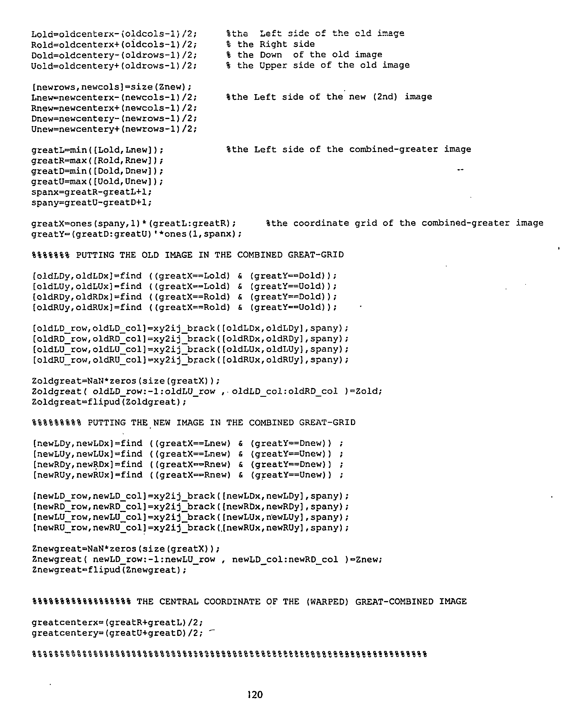


Claims (20)
Priority Applications (1)
| Application Number | Priority Date | Filing Date | Title |
|---|---|---|---|
| US10/312,891 US7440637B2 (en) | 2000-07-21 | 2001-07-23 | Method and apparatus for image mosaicing |
Applications Claiming Priority (3)
| Application Number | Priority Date | Filing Date | Title |
|---|---|---|---|
| US22002500P | 2000-07-21 | 2000-07-21 | |
| PCT/US2001/023159 WO2002009424A2 (en) | 2000-07-21 | 2001-07-23 | Method and apparatus for image mosaicing |
| US10/312,891 US7440637B2 (en) | 2000-07-21 | 2001-07-23 | Method and apparatus for image mosaicing |
Publications (2)
| Publication Number | Publication Date |
|---|---|
| US20040056966A1 true US20040056966A1 (en) | 2004-03-25 |
| US7440637B2 US7440637B2 (en) | 2008-10-21 |
Family
ID=22821741
Family Applications (1)
| Application Number | Title | Priority Date | Filing Date |
|---|---|---|---|
| US10/312,891 Active 2024-12-22 US7440637B2 (en) | 2000-07-21 | 2001-07-23 | Method and apparatus for image mosaicing |
Country Status (6)
| Country | Link |
|---|---|
| US (1) | US7440637B2 (en) |
| JP (1) | JP4015944B2 (en) |
| KR (1) | KR20030028553A (en) |
| CN (1) | CN1451230A (en) |
| AU (1) | AU2001277964A1 (en) |
| WO (1) | WO2002009424A2 (en) |
Cited By (115)
| Publication number | Priority date | Publication date | Assignee | Title |
|---|---|---|---|---|
| US20020176007A1 (en) * | 2001-02-24 | 2002-11-28 | Markus Cappellaro | Method for recording and displaying fluorescence images with a high spatial resolution |
| US20050185062A1 (en) * | 2004-02-24 | 2005-08-25 | Hillis W. D. | Volumetric imaging using "virtual'' lenslets |
| WO2005081836A2 (en) * | 2004-02-24 | 2005-09-09 | Searete Llc | Defect correction based on 'virtual' lenslets |
| US20050225761A1 (en) * | 2004-04-13 | 2005-10-13 | The United States Of America As Represented By The Secretary Of The Army | Simultaneous 4-stokes parameter determination using a single digital image |
| US20050275630A1 (en) * | 2004-05-25 | 2005-12-15 | Butterworth Mark M | Apparatus for capturing and analyzing light and method embodied therein |
| US20060023276A1 (en) * | 2004-07-27 | 2006-02-02 | Samsung Electronics Co., Ltd. | Digital imaging apparatus capable of creating panorama image and a creating method thereof |
| US20070031063A1 (en) * | 2005-08-05 | 2007-02-08 | Hui Zhou | Method and apparatus for generating a composite image from a set of images |
| US20070166020A1 (en) * | 2006-01-19 | 2007-07-19 | Shuxue Quan | Hand jitter reduction system for cameras |
| WO2007087405A2 (en) * | 2006-01-24 | 2007-08-02 | The Trustees Of Columbia University In The City Of New York | Capturing scene images and depth geometry and generating a compensation image |
| US20070194858A1 (en) * | 2006-02-22 | 2007-08-23 | Samsung Electronics Co., Ltd. | Method and apparatus for recording and reproducing multimedia data |
| US7274449B1 (en) | 2005-06-20 | 2007-09-25 | United States Of America As Represented By The Secretary Of The Army | System for determining stokes parameters |
| US7273562B2 (en) * | 2002-04-17 | 2007-09-25 | Nutech 03, Inc. | Ozone injection method and system |
| US7295312B1 (en) * | 2006-05-10 | 2007-11-13 | United States Of America As Represented By The Secretary Of The Army | Rapid 4-Stokes parameter determination via Stokes filter wheel |
| US20080137077A1 (en) * | 2006-12-08 | 2008-06-12 | Hillis W Daniel | Defect correction based on "virtual" lenslets |
| US20080192129A1 (en) * | 2003-12-24 | 2008-08-14 | Walker Jay S | Method and Apparatus for Automatically Capturing and Managing Images |
| US20080234548A1 (en) * | 2007-03-20 | 2008-09-25 | Pascal Amit | Narrow band in-vivo imaging device |
| US20080309929A1 (en) * | 2007-06-15 | 2008-12-18 | Historx, Inc. | Method and system for standardizing microscope instruments |
| US20090034823A1 (en) * | 2007-05-14 | 2009-02-05 | Historx, Inc. | Compartment segregation by pixel characterization using image data clustering |
| US20090046163A1 (en) * | 2004-02-24 | 2009-02-19 | Searete Llc, A Limited Liability Corporation Of The State Of Delaware | Volumetric imaging using "virtual" lenslets |
| US20090074266A1 (en) * | 2007-08-07 | 2009-03-19 | Historx, Inc. | Method and system for determining an optimal dilution of a reagent |
| US20090074282A1 (en) * | 2007-08-06 | 2009-03-19 | Historx, Inc. | Methods and system for validating sample images for quantitative immunoassays |
| US20090086046A1 (en) * | 2007-08-31 | 2009-04-02 | Historx, Inc. | Automatic exposure time selection for imaging tissue |
| EP2055095A1 (en) * | 2006-08-25 | 2009-05-06 | Eliezer Jacob | Improved digital camera with non-uniform image resolution |
| US20090128643A1 (en) * | 2005-01-18 | 2009-05-21 | Tetsujiro Kondo | Image Pickup Apparatus, Method for Capturing Image, and Method for Designing Image Pickup Apparatus |
| US20100136549A1 (en) * | 2008-09-16 | 2010-06-03 | Historx, Inc. | Reproducible quantification of biomarker expression |
| US20110069189A1 (en) * | 2008-05-20 | 2011-03-24 | Pelican Imaging Corporation | Capturing and processing of images using monolithic camera array with heterogeneous imagers |
| US20110080487A1 (en) * | 2008-05-20 | 2011-04-07 | Pelican Imaging Corporation | Capturing and processing of images using monolithic camera array with heterogeneous imagers |
| US20110115928A1 (en) * | 2006-06-05 | 2011-05-19 | Tessera Technologies Ireland Limited | Image Acquisition Method and Apparatus |
| US7970239B2 (en) | 2006-01-19 | 2011-06-28 | Qualcomm Incorporated | Hand jitter reduction compensating for rotational motion |
| US20110157320A1 (en) * | 2009-07-22 | 2011-06-30 | Ichiro Oyama | Parallax detecting apparatus, distance measuring apparatus, and parallax detecting method |
| US20110157396A1 (en) * | 2009-12-28 | 2011-06-30 | Canon Kabushiki Kaisha | Image processing apparatus, image processing method, and storage medium |
| US8019179B2 (en) | 2006-01-19 | 2011-09-13 | Qualcomm Incorporated | Hand jitter reduction for compensating for linear displacement |
| US20110258525A1 (en) * | 2000-08-22 | 2011-10-20 | Affymetrix, Inc. | System, method, and computer software for linked window interfaces |
| US20110268347A1 (en) * | 2010-04-30 | 2011-11-03 | Complete Genomics, Inc. | Method and system for accurate alignment and registration of array for dna sequencing |
| US20130002715A1 (en) * | 2011-06-28 | 2013-01-03 | Tidman James M | Image Sequence Reconstruction based on Overlapping Measurement Subsets |
| US20130023773A1 (en) * | 2010-04-07 | 2013-01-24 | Stc. Unm | Apparatus and techniques of non-invasive analysis |
| US20130050429A1 (en) * | 2011-08-24 | 2013-02-28 | Sony Corporation | Image processing device, method of controlling image processing device and program causing computer to execute method |
| WO2013043761A1 (en) * | 2011-09-19 | 2013-03-28 | Pelican Imaging Corporation | Determining depth from multiple views of a scene that include aliasing using hypothesized fusion |
| US20130107956A1 (en) * | 2010-07-06 | 2013-05-02 | Koninklijke Philips Electronics N.V. | Generation of high dynamic range images from low dynamic range images |
| US20130120615A1 (en) * | 2011-11-11 | 2013-05-16 | Shinichiro Hirooka | Imaging device |
| US8619082B1 (en) | 2012-08-21 | 2013-12-31 | Pelican Imaging Corporation | Systems and methods for parallax detection and correction in images captured using array cameras that contain occlusions using subsets of images to perform depth estimation |
| US20140055771A1 (en) * | 2012-02-15 | 2014-02-27 | Mesa Imaging Ag | Time of Flight Camera with Stripe Illumination |
| US8698916B2 (en) | 2003-08-05 | 2014-04-15 | DigitalOptics Corporation Europe Limited | Red-eye filter method and apparatus |
| TWI448808B (en) * | 2008-01-25 | 2014-08-11 | Chi Mei Comm Systems Inc | System and method for adjusting focus of a projection automatically |
| US8804255B2 (en) | 2011-06-28 | 2014-08-12 | Pelican Imaging Corporation | Optical arrangements for use with an array camera |
| US8831367B2 (en) | 2011-09-28 | 2014-09-09 | Pelican Imaging Corporation | Systems and methods for decoding light field image files |
| US8861089B2 (en) | 2009-11-20 | 2014-10-14 | Pelican Imaging Corporation | Capturing and processing of images using monolithic camera array with heterogeneous imagers |
| US8866912B2 (en) | 2013-03-10 | 2014-10-21 | Pelican Imaging Corporation | System and methods for calibration of an array camera using a single captured image |
| US8878950B2 (en) | 2010-12-14 | 2014-11-04 | Pelican Imaging Corporation | Systems and methods for synthesizing high resolution images using super-resolution processes |
| US8928793B2 (en) | 2010-05-12 | 2015-01-06 | Pelican Imaging Corporation | Imager array interfaces |
| EP2843938A3 (en) * | 2013-08-29 | 2015-03-25 | Nokia Corporation | Method, apparatus and computer program product for sensing of visible spectrum and near infrared spectrum |
| US20150208005A1 (en) * | 2014-01-23 | 2015-07-23 | Robert Bosch Gmbh | Camera system, especially for a vehicle, and method for ascertaining image information of a signal source pulsed as a function of time |
| US9100586B2 (en) | 2013-03-14 | 2015-08-04 | Pelican Imaging Corporation | Systems and methods for photometric normalization in array cameras |
| US9100635B2 (en) | 2012-06-28 | 2015-08-04 | Pelican Imaging Corporation | Systems and methods for detecting defective camera arrays and optic arrays |
| US20150219498A1 (en) * | 2014-02-06 | 2015-08-06 | The Boeing Company | Systems and Methods for Measuring Polarization of Light in Images |
| US9106784B2 (en) | 2013-03-13 | 2015-08-11 | Pelican Imaging Corporation | Systems and methods for controlling aliasing in images captured by an array camera for use in super-resolution processing |
| US9124831B2 (en) | 2013-03-13 | 2015-09-01 | Pelican Imaging Corporation | System and methods for calibration of an array camera |
| US9143711B2 (en) | 2012-11-13 | 2015-09-22 | Pelican Imaging Corporation | Systems and methods for array camera focal plane control |
| US9185276B2 (en) | 2013-11-07 | 2015-11-10 | Pelican Imaging Corporation | Methods of manufacturing array camera modules incorporating independently aligned lens stacks |
| US9197821B2 (en) | 2011-05-11 | 2015-11-24 | Pelican Imaging Corporation | Systems and methods for transmitting and receiving array camera image data |
| US9210392B2 (en) | 2012-05-01 | 2015-12-08 | Pelican Imaging Coporation | Camera modules patterned with pi filter groups |
| US9214013B2 (en) | 2012-09-14 | 2015-12-15 | Pelican Imaging Corporation | Systems and methods for correcting user identified artifacts in light field images |
| US9247117B2 (en) | 2014-04-07 | 2016-01-26 | Pelican Imaging Corporation | Systems and methods for correcting for warpage of a sensor array in an array camera module by introducing warpage into a focal plane of a lens stack array |
| US9253380B2 (en) | 2013-02-24 | 2016-02-02 | Pelican Imaging Corporation | Thin form factor computational array cameras and modular array cameras |
| US20160191759A1 (en) * | 2014-12-29 | 2016-06-30 | Intel Corporation | Method and system of lens shift correction for a camera array |
| US9412206B2 (en) | 2012-02-21 | 2016-08-09 | Pelican Imaging Corporation | Systems and methods for the manipulation of captured light field image data |
| US9426361B2 (en) | 2013-11-26 | 2016-08-23 | Pelican Imaging Corporation | Array camera configurations incorporating multiple constituent array cameras |
| US9432193B1 (en) * | 2015-02-05 | 2016-08-30 | Sensory, Incorporated | Face-based authentication with situational adaptivity |
| US9438888B2 (en) | 2013-03-15 | 2016-09-06 | Pelican Imaging Corporation | Systems and methods for stereo imaging with camera arrays |
| US9445003B1 (en) | 2013-03-15 | 2016-09-13 | Pelican Imaging Corporation | Systems and methods for synthesizing high resolution images using image deconvolution based on motion and depth information |
| US9462164B2 (en) | 2013-02-21 | 2016-10-04 | Pelican Imaging Corporation | Systems and methods for generating compressed light field representation data using captured light fields, array geometry, and parallax information |
| US9497370B2 (en) | 2013-03-15 | 2016-11-15 | Pelican Imaging Corporation | Array camera architecture implementing quantum dot color filters |
| US9497429B2 (en) | 2013-03-15 | 2016-11-15 | Pelican Imaging Corporation | Extended color processing on pelican array cameras |
| US9516222B2 (en) | 2011-06-28 | 2016-12-06 | Kip Peli P1 Lp | Array cameras incorporating monolithic array camera modules with high MTF lens stacks for capture of images used in super-resolution processing |
| US9519972B2 (en) | 2013-03-13 | 2016-12-13 | Kip Peli P1 Lp | Systems and methods for synthesizing images from image data captured by an array camera using restricted depth of field depth maps in which depth estimation precision varies |
| US9521319B2 (en) | 2014-06-18 | 2016-12-13 | Pelican Imaging Corporation | Array cameras and array camera modules including spectral filters disposed outside of a constituent image sensor |
| US9521416B1 (en) | 2013-03-11 | 2016-12-13 | Kip Peli P1 Lp | Systems and methods for image data compression |
| US20160370175A1 (en) * | 2015-06-22 | 2016-12-22 | The Johns Hopkins University | Hardware and System for Single-Camera Stereo Range Determination |
| US9571732B2 (en) | 2013-03-21 | 2017-02-14 | Lg Electronics Inc. | Display device and method for controlling the same |
| US9578259B2 (en) | 2013-03-14 | 2017-02-21 | Fotonation Cayman Limited | Systems and methods for reducing motion blur in images or video in ultra low light with array cameras |
| US9633442B2 (en) | 2013-03-15 | 2017-04-25 | Fotonation Cayman Limited | Array cameras including an array camera module augmented with a separate camera |
| US9638883B1 (en) | 2013-03-04 | 2017-05-02 | Fotonation Cayman Limited | Passive alignment of array camera modules constructed from lens stack arrays and sensors based upon alignment information obtained during manufacture of array camera modules using an active alignment process |
| US9766380B2 (en) | 2012-06-30 | 2017-09-19 | Fotonation Cayman Limited | Systems and methods for manufacturing camera modules using active alignment of lens stack arrays and sensors |
| US9774789B2 (en) | 2013-03-08 | 2017-09-26 | Fotonation Cayman Limited | Systems and methods for high dynamic range imaging using array cameras |
| US9813616B2 (en) | 2012-08-23 | 2017-11-07 | Fotonation Cayman Limited | Feature based high resolution motion estimation from low resolution images captured using an array source |
| US20170374297A1 (en) * | 2016-06-28 | 2017-12-28 | U.S.A. As Represented By The Administrator Of The National Aeronautics And Space Administration | Compact, high resolution thermal infrared imager |
| US20180003562A1 (en) * | 2016-06-30 | 2018-01-04 | Fuji Xerox Co., Ltd. | Information processor, non-transitory computer readable medium, and information processing method |
| US9888194B2 (en) | 2013-03-13 | 2018-02-06 | Fotonation Cayman Limited | Array camera architecture implementing quantum film image sensors |
| US9898856B2 (en) | 2013-09-27 | 2018-02-20 | Fotonation Cayman Limited | Systems and methods for depth-assisted perspective distortion correction |
| US9942474B2 (en) | 2015-04-17 | 2018-04-10 | Fotonation Cayman Limited | Systems and methods for performing high speed video capture and depth estimation using array cameras |
| US10089740B2 (en) | 2014-03-07 | 2018-10-02 | Fotonation Limited | System and methods for depth regularization and semiautomatic interactive matting using RGB-D images |
| WO2018176493A1 (en) * | 2017-04-01 | 2018-10-04 | SZ DJI Technology Co., Ltd. | Low-profile multi-band hyperspectral imaging for machine vision |
| US10119808B2 (en) | 2013-11-18 | 2018-11-06 | Fotonation Limited | Systems and methods for estimating depth from projected texture using camera arrays |
| US10122993B2 (en) | 2013-03-15 | 2018-11-06 | Fotonation Limited | Autofocus system for a conventional camera that uses depth information from an array camera |
| US20190052792A1 (en) * | 2017-08-11 | 2019-02-14 | Ut-Battelle, Llc | Optical array for high-quality imaging in harsh environments |
| US10241204B2 (en) * | 2013-11-14 | 2019-03-26 | Odos Imaging Ltd. | Method for illuminating an object |
| US10250871B2 (en) | 2014-09-29 | 2019-04-02 | Fotonation Limited | Systems and methods for dynamic calibration of array cameras |
| US10390005B2 (en) | 2012-09-28 | 2019-08-20 | Fotonation Limited | Generating images from light fields utilizing virtual viewpoints |
| US20190265457A1 (en) * | 2013-04-26 | 2019-08-29 | Hamamatsu Photonics K.K. | Image acquisition device and method and system for acquiring focusing information for specimen |
| US10482618B2 (en) | 2017-08-21 | 2019-11-19 | Fotonation Limited | Systems and methods for hybrid depth regularization |
| CN110784641A (en) * | 2018-07-30 | 2020-02-11 | 安讯士有限公司 | Method for combining views from multiple cameras and camera system |
| US20200167942A1 (en) * | 2018-11-27 | 2020-05-28 | Infineon Technologies Ag | Filtering Continous-Wave Time-of-Flight Measurements, Based on Coded Modulation Images |
| US10901197B2 (en) | 2014-09-19 | 2021-01-26 | Sony Corporation | Medical observation device and lens barrel of medical observation device |
| US11073610B2 (en) * | 2019-01-31 | 2021-07-27 | International Business Machines Corporation | Portable imager |
| WO2021158804A1 (en) * | 2020-02-06 | 2021-08-12 | Valve Corporation | Position tracking system for head-mounted display systems |
| US11270110B2 (en) | 2019-09-17 | 2022-03-08 | Boston Polarimetrics, Inc. | Systems and methods for surface modeling using polarization cues |
| US11290658B1 (en) | 2021-04-15 | 2022-03-29 | Boston Polarimetrics, Inc. | Systems and methods for camera exposure control |
| US11302012B2 (en) | 2019-11-30 | 2022-04-12 | Boston Polarimetrics, Inc. | Systems and methods for transparent object segmentation using polarization cues |
| US11525906B2 (en) | 2019-10-07 | 2022-12-13 | Intrinsic Innovation Llc | Systems and methods for augmentation of sensor systems and imaging systems with polarization |
| US11580667B2 (en) | 2020-01-29 | 2023-02-14 | Intrinsic Innovation Llc | Systems and methods for characterizing object pose detection and measurement systems |
| US11689813B2 (en) | 2021-07-01 | 2023-06-27 | Intrinsic Innovation Llc | Systems and methods for high dynamic range imaging using crossed polarizers |
| US11792538B2 (en) | 2008-05-20 | 2023-10-17 | Adeia Imaging Llc | Capturing and processing of images including occlusions focused on an image sensor by a lens stack array |
| US11797863B2 (en) | 2020-01-30 | 2023-10-24 | Intrinsic Innovation Llc | Systems and methods for synthesizing data for training statistical models on different imaging modalities including polarized images |
| US11954886B2 (en) | 2021-04-15 | 2024-04-09 | Intrinsic Innovation Llc | Systems and methods for six-degree of freedom pose estimation of deformable objects |
| US11953700B2 (en) | 2020-05-27 | 2024-04-09 | Intrinsic Innovation Llc | Multi-aperture polarization optical systems using beam splitters |
Families Citing this family (26)
| Publication number | Priority date | Publication date | Assignee | Title |
|---|---|---|---|---|
| US7542592B2 (en) * | 2004-03-29 | 2009-06-02 | Siemesn Corporate Research, Inc. | Systems and methods for face detection and recognition using infrared imaging |
| EP1761041A1 (en) * | 2005-08-29 | 2007-03-07 | Stueckler Gerd | Digital motion picture camera |
| JP2007318490A (en) * | 2006-05-26 | 2007-12-06 | Olympus Imaging Corp | Image processing apparatus, camera, and image processing program |
| US8218822B2 (en) * | 2007-05-14 | 2012-07-10 | Pips Technology, Inc. | Apparatus and method for recognizing the state of origin of a vehicle license plate |
| JP5261796B2 (en) * | 2008-02-05 | 2013-08-14 | 富士フイルム株式会社 | Imaging apparatus, imaging method, image processing apparatus, image processing method, and program |
| JP4507265B2 (en) * | 2008-06-30 | 2010-07-21 | ルネサスエレクトロニクス株式会社 | Image processing circuit, and display panel driver and display device having the same |
| US8391634B1 (en) | 2009-04-28 | 2013-03-05 | Google Inc. | Illumination estimation for images |
| US8723118B2 (en) | 2009-10-01 | 2014-05-13 | Microsoft Corporation | Imager for constructing color and depth images |
| US20130188878A1 (en) * | 2010-07-20 | 2013-07-25 | Lockheed Martin Corporation | Image analysis systems having image sharpening capabilities and methods using same |
| US9294755B2 (en) * | 2010-10-20 | 2016-03-22 | Raytheon Company | Correcting frame-to-frame image changes due to motion for three dimensional (3-D) persistent observations |
| US8798393B2 (en) * | 2010-12-01 | 2014-08-05 | Google Inc. | Removing illumination variation from images |
| US8923401B2 (en) | 2011-05-31 | 2014-12-30 | Raytheon Company | Hybrid motion image compression |
| CN102538757A (en) * | 2011-11-08 | 2012-07-04 | 昆明理工大学 | Method for observing bright source and surrounding dark source targets |
| US9230333B2 (en) | 2012-02-22 | 2016-01-05 | Raytheon Company | Method and apparatus for image processing |
| FR3005226B1 (en) * | 2013-04-25 | 2015-04-10 | Astrium Sas | IMAGE ENTRY WITH ADDITION OF ACCUMULATION SIGNALS FOR ADJACENT PHOTODETECTORS |
| WO2015171544A1 (en) | 2014-05-06 | 2015-11-12 | Niazi Zakariya | Imaging system, method, and applications |
| CN104267265B (en) * | 2014-09-30 | 2017-02-08 | 中国科学院新疆天文台 | Evaluating system and method based on radio astronomical instrument device electromagnetic radiation |
| US9723197B2 (en) | 2015-03-31 | 2017-08-01 | Sony Corporation | Depth estimation from image defocus using multiple resolution Gaussian difference |
| US10048127B2 (en) | 2015-08-05 | 2018-08-14 | Viavi Solutions Inc. | Optical filter and spectrometer |
| TW201716933A (en) * | 2015-11-06 | 2017-05-16 | 原相科技股份有限公司 | Optical navigation apparatus with blurs image compensatory function and compensation circuit thereof |
| US10523873B2 (en) * | 2015-11-19 | 2019-12-31 | Sony Corporation | Image processing device and image processing method |
| US10412280B2 (en) | 2016-02-10 | 2019-09-10 | Microsoft Technology Licensing, Llc | Camera with light valve over sensor array |
| US10341565B2 (en) | 2016-05-10 | 2019-07-02 | Raytheon Company | Self correcting adaptive low light optical payload |
| CN107370962B (en) * | 2016-07-29 | 2019-10-15 | Oppo广东移动通信有限公司 | High dynamic range images image pickup method, device and terminal device |
| JP6662745B2 (en) * | 2016-10-04 | 2020-03-11 | 株式会社ソニー・インタラクティブエンタテインメント | Imaging device, information processing system, and polarization image processing method |
| CN114166348B (en) * | 2021-12-16 | 2023-09-19 | 中国科学院光电技术研究所 | Rapid polarization imaging method based on full Stokes vector |
Citations (3)
| Publication number | Priority date | Publication date | Assignee | Title |
|---|---|---|---|---|
| US6078701A (en) * | 1997-08-01 | 2000-06-20 | Sarnoff Corporation | Method and apparatus for performing local to global multiframe alignment to construct mosaic images |
| US6454410B1 (en) * | 1999-10-20 | 2002-09-24 | The Trustees Of The University Of Pennsylvania | Mosaicing and enhancement of images for ophthalmic diagnosis and documentation |
| US6909459B2 (en) * | 2002-08-21 | 2005-06-21 | Alpha Innotech Corporation | Method of and apparatus for extending signal ranges of digital images |
Family Cites Families (6)
| Publication number | Priority date | Publication date | Assignee | Title |
|---|---|---|---|---|
| JPS6133638A (en) * | 1984-07-26 | 1986-02-17 | オリンパス光学工業株式会社 | Endoscope photographing apparatus |
| JPH01115808A (en) * | 1987-10-29 | 1989-05-09 | Toshiba Corp | Rare gas recover device |
| JP2883648B2 (en) * | 1988-10-03 | 1999-04-19 | オリンパス光学工業株式会社 | Image input / output device |
| JPH11155808A (en) * | 1997-11-27 | 1999-06-15 | Olympus Optical Co Ltd | Endoscope image pickup device |
| JPH11331686A (en) * | 1998-05-14 | 1999-11-30 | Matsushita Electric Ind Co Ltd | Image input device |
| GB2341029B (en) * | 1998-08-29 | 2002-12-31 | Marconi Gec Ltd | Cameras |
-
2001
- 2001-07-23 WO PCT/US2001/023159 patent/WO2002009424A2/en active Application Filing
- 2001-07-23 US US10/312,891 patent/US7440637B2/en active Active
- 2001-07-23 CN CN01813115A patent/CN1451230A/en active Pending
- 2001-07-23 AU AU2001277964A patent/AU2001277964A1/en not_active Abandoned
- 2001-07-23 KR KR10-2003-7000939A patent/KR20030028553A/en not_active Application Discontinuation
- 2001-07-23 JP JP2002515013A patent/JP4015944B2/en not_active Expired - Fee Related
Patent Citations (3)
| Publication number | Priority date | Publication date | Assignee | Title |
|---|---|---|---|---|
| US6078701A (en) * | 1997-08-01 | 2000-06-20 | Sarnoff Corporation | Method and apparatus for performing local to global multiframe alignment to construct mosaic images |
| US6454410B1 (en) * | 1999-10-20 | 2002-09-24 | The Trustees Of The University Of Pennsylvania | Mosaicing and enhancement of images for ophthalmic diagnosis and documentation |
| US6909459B2 (en) * | 2002-08-21 | 2005-06-21 | Alpha Innotech Corporation | Method of and apparatus for extending signal ranges of digital images |
Cited By (313)
| Publication number | Priority date | Publication date | Assignee | Title |
|---|---|---|---|---|
| US20110258525A1 (en) * | 2000-08-22 | 2011-10-20 | Affymetrix, Inc. | System, method, and computer software for linked window interfaces |
| US7113205B2 (en) * | 2001-02-24 | 2006-09-26 | Carl-Zeiss-Stiftung | Method for recording and displaying fluorescence images with a high spatial resolution |
| US20020176007A1 (en) * | 2001-02-24 | 2002-11-28 | Markus Cappellaro | Method for recording and displaying fluorescence images with a high spatial resolution |
| US7273562B2 (en) * | 2002-04-17 | 2007-09-25 | Nutech 03, Inc. | Ozone injection method and system |
| US8698916B2 (en) | 2003-08-05 | 2014-04-15 | DigitalOptics Corporation Europe Limited | Red-eye filter method and apparatus |
| US8885074B2 (en) | 2003-08-05 | 2014-11-11 | DigitalOptics Corporation Europe Limited | Red-eye filter method and apparatus |
| US7924323B2 (en) * | 2003-12-24 | 2011-04-12 | Walker Digital, Llc | Method and apparatus for automatically capturing and managing images |
| US20080192129A1 (en) * | 2003-12-24 | 2008-08-14 | Walker Jay S | Method and Apparatus for Automatically Capturing and Managing Images |
| US8238620B2 (en) * | 2004-02-24 | 2012-08-07 | The Invention Science Fund I, Llc | Defect correction based on “virtual” lenslets |
| WO2005081836A2 (en) * | 2004-02-24 | 2005-09-09 | Searete Llc | Defect correction based on 'virtual' lenslets |
| US8169534B2 (en) | 2004-02-24 | 2012-05-01 | The Invention Science Fund I, Llc | Volumetric imaging using “virtual” lenslets |
| WO2005081823A3 (en) * | 2004-02-24 | 2007-02-08 | Searete Llc | Volumetric imaging using 'virtual' lenslets |
| US20050185062A1 (en) * | 2004-02-24 | 2005-08-25 | Hillis W. D. | Volumetric imaging using "virtual'' lenslets |
| US7220001B2 (en) * | 2004-02-24 | 2007-05-22 | Searete, Llc | Defect correction based on “virtual” lenslets |
| US7232221B2 (en) * | 2004-02-24 | 2007-06-19 | Searete, Llc | Volumetric imaging using “virtual” lenslets |
| US7399082B2 (en) | 2004-02-24 | 2008-07-15 | Searete, Llc | Volumetric imaging using “virtual” lenslets |
| WO2005081823A2 (en) * | 2004-02-24 | 2005-09-09 | Searete Llc | Volumetric imaging using 'virtual' lenslets |
| US20050200807A1 (en) * | 2004-02-24 | 2005-09-15 | Hillis W. D. | Defect correction based on "virtual" lenslets |
| US20090046163A1 (en) * | 2004-02-24 | 2009-02-19 | Searete Llc, A Limited Liability Corporation Of The State Of Delaware | Volumetric imaging using "virtual" lenslets |
| WO2005081836A3 (en) * | 2004-02-24 | 2006-10-26 | Searete Llc | Defect correction based on 'virtual' lenslets |
| US20110169855A1 (en) * | 2004-02-24 | 2011-07-14 | Hillis W Daniel | Defect correction based on "virtual" lenslets |
| US20050225761A1 (en) * | 2004-04-13 | 2005-10-13 | The United States Of America As Represented By The Secretary Of The Army | Simultaneous 4-stokes parameter determination using a single digital image |
| US7173698B2 (en) * | 2004-04-13 | 2007-02-06 | The United States Of America As Represented By The Secretary Of The Army | Simultaneous 4-stokes parameter determination using a single digital image |
| US8259067B2 (en) * | 2004-05-25 | 2012-09-04 | Avago Technologies Ecbu Ip (Singapore) Pte. Ltd. | Apparatus for capturing and analyzing light and method embodied therein |
| US20080278449A1 (en) * | 2004-05-25 | 2008-11-13 | Avago Technologies Ecbu Ip (Singapore) Pte. Ltd. | Apparatus for capturing and analyzing light and method embodied therein |
| US20050275630A1 (en) * | 2004-05-25 | 2005-12-15 | Butterworth Mark M | Apparatus for capturing and analyzing light and method embodied therein |
| US7420542B2 (en) * | 2004-05-25 | 2008-09-02 | Avago Technologies Ecbu Ip Pte Ltd | Apparatus for capturing and analyzing light and method embodied therein |
| US7593635B2 (en) * | 2004-07-27 | 2009-09-22 | Samsung Electronics Co., Ltd. | Digital imaging apparatus capable of creating panorama image and a creating method thereof |
| US20060023276A1 (en) * | 2004-07-27 | 2006-02-02 | Samsung Electronics Co., Ltd. | Digital imaging apparatus capable of creating panorama image and a creating method thereof |
| US8031232B2 (en) * | 2005-01-18 | 2011-10-04 | Sony Corporation | Image pickup apparatus including a first image formation system and a second image formation system, method for capturing image, and method for designing image pickup apparatus |
| US20090128643A1 (en) * | 2005-01-18 | 2009-05-21 | Tetsujiro Kondo | Image Pickup Apparatus, Method for Capturing Image, and Method for Designing Image Pickup Apparatus |
| US7274449B1 (en) | 2005-06-20 | 2007-09-25 | United States Of America As Represented By The Secretary Of The Army | System for determining stokes parameters |
| US20070031063A1 (en) * | 2005-08-05 | 2007-02-08 | Hui Zhou | Method and apparatus for generating a composite image from a set of images |
| US7970239B2 (en) | 2006-01-19 | 2011-06-28 | Qualcomm Incorporated | Hand jitter reduction compensating for rotational motion |
| US8120658B2 (en) * | 2006-01-19 | 2012-02-21 | Qualcomm Incorporated | Hand jitter reduction system for cameras |
| US8019179B2 (en) | 2006-01-19 | 2011-09-13 | Qualcomm Incorporated | Hand jitter reduction for compensating for linear displacement |
| US20070166020A1 (en) * | 2006-01-19 | 2007-07-19 | Shuxue Quan | Hand jitter reduction system for cameras |
| US9122946B2 (en) | 2006-01-24 | 2015-09-01 | The Trustees Of Columbia University In The City Of New York | Systems, methods, and media for capturing scene images and depth geometry and generating a compensation image |
| US20090244090A1 (en) * | 2006-01-24 | 2009-10-01 | Li Zhang | Systems, methods, and media for capturing scene images and depth geometry and generating a compensation image |
| WO2007087405A2 (en) * | 2006-01-24 | 2007-08-02 | The Trustees Of Columbia University In The City Of New York | Capturing scene images and depth geometry and generating a compensation image |
| WO2007087405A3 (en) * | 2006-01-24 | 2008-07-24 | Univ Columbia | Capturing scene images and depth geometry and generating a compensation image |
| US20070194858A1 (en) * | 2006-02-22 | 2007-08-23 | Samsung Electronics Co., Ltd. | Method and apparatus for recording and reproducing multimedia data |
| US7295312B1 (en) * | 2006-05-10 | 2007-11-13 | United States Of America As Represented By The Secretary Of The Army | Rapid 4-Stokes parameter determination via Stokes filter wheel |
| US20070263218A1 (en) * | 2006-05-10 | 2007-11-15 | The United States Of America As Represented By The Army | Rapid 4-Stokes parameter determination via stokes filter |
| US20110115928A1 (en) * | 2006-06-05 | 2011-05-19 | Tessera Technologies Ireland Limited | Image Acquisition Method and Apparatus |
| US8520082B2 (en) | 2006-06-05 | 2013-08-27 | DigitalOptics Corporation Europe Limited | Image acquisition method and apparatus |
| EP2055095A1 (en) * | 2006-08-25 | 2009-05-06 | Eliezer Jacob | Improved digital camera with non-uniform image resolution |
| EP2055095A4 (en) * | 2006-08-25 | 2012-06-27 | Eliezer Jacob | Improved digital camera with non-uniform image resolution |
| US20080137077A1 (en) * | 2006-12-08 | 2008-06-12 | Hillis W Daniel | Defect correction based on "virtual" lenslets |
| US7840038B2 (en) * | 2006-12-08 | 2010-11-23 | The Invention Science Fund I, Llc | Defect correction based on “virtual” lenslets |
| US20080234548A1 (en) * | 2007-03-20 | 2008-09-25 | Pascal Amit | Narrow band in-vivo imaging device |
| US9730573B2 (en) | 2007-03-20 | 2017-08-15 | Given Imaging Ltd. | Narrow band in-vivo imaging device |
| WO2008114260A3 (en) * | 2007-03-20 | 2010-02-25 | Given Imaging Ltd. | Narrow band in-vivo imaging device |
| US8335360B2 (en) | 2007-05-14 | 2012-12-18 | Historx, Inc. | Compartment segregation by pixel characterization using image data clustering |
| US20090034823A1 (en) * | 2007-05-14 | 2009-02-05 | Historx, Inc. | Compartment segregation by pixel characterization using image data clustering |
| US8655037B2 (en) | 2007-05-14 | 2014-02-18 | Historx, Inc. | Compartment segregation by pixel characterization using image data clustering |
| US20110299070A1 (en) * | 2007-06-15 | 2011-12-08 | Historx, Inc. | Method and system for standardizing microscope instruments |
| US20110116086A1 (en) * | 2007-06-15 | 2011-05-19 | Historx, Inc. | Method and system for standardizing microscope instruments |
| US9080978B2 (en) * | 2007-06-15 | 2015-07-14 | Novartis Ag | Method and system for standardizing microscope instruments |
| US8027030B2 (en) * | 2007-06-15 | 2011-09-27 | Historx, Inc. | Method and system for standardizing microscope instruments |
| US8120768B2 (en) * | 2007-06-15 | 2012-02-21 | Historx, Inc. | Method and system for standardizing microscope instruments |
| US8427635B2 (en) * | 2007-06-15 | 2013-04-23 | Historx, Inc. | Method and system for standardizing microscope instruments |
| US7907271B2 (en) * | 2007-06-15 | 2011-03-15 | Historx, Inc. | Method and system for standardizing microscope instruments |
| US20130310268A1 (en) * | 2007-06-15 | 2013-11-21 | Historx, Inc. | Method and system for standarizing microscope instruments |
| US20080309929A1 (en) * | 2007-06-15 | 2008-12-18 | Historx, Inc. | Method and system for standardizing microscope instruments |
| US20120133930A1 (en) * | 2007-06-15 | 2012-05-31 | Historx, Inc. | Method and system for standardizing microscope instruments |
| US8314931B2 (en) * | 2007-06-15 | 2012-11-20 | Historx, Inc. | Method and system for standardizing microscope instruments |
| US20110116087A1 (en) * | 2007-06-15 | 2011-05-19 | Historx, Inc. | Method and system for standardizing microscope instruments |
| US20090074282A1 (en) * | 2007-08-06 | 2009-03-19 | Historx, Inc. | Methods and system for validating sample images for quantitative immunoassays |
| US8417015B2 (en) | 2007-08-06 | 2013-04-09 | Historx, Inc. | Methods and system for validating sample images for quantitative immunoassays |
| US8160348B2 (en) | 2007-08-06 | 2012-04-17 | Historx, Inc. | Methods and system for validating sample images for quantitative immunoassays |
| US20090074266A1 (en) * | 2007-08-07 | 2009-03-19 | Historx, Inc. | Method and system for determining an optimal dilution of a reagent |
| US8121365B2 (en) | 2007-08-07 | 2012-02-21 | Historx, Inc. | Method and system for determining an optimal dilution of a reagent |
| US20090086046A1 (en) * | 2007-08-31 | 2009-04-02 | Historx, Inc. | Automatic exposure time selection for imaging tissue |
| US7978258B2 (en) | 2007-08-31 | 2011-07-12 | Historx, Inc. | Automatic exposure time selection for imaging tissue |
| TWI448808B (en) * | 2008-01-25 | 2014-08-11 | Chi Mei Comm Systems Inc | System and method for adjusting focus of a projection automatically |
| US11792538B2 (en) | 2008-05-20 | 2023-10-17 | Adeia Imaging Llc | Capturing and processing of images including occlusions focused on an image sensor by a lens stack array |
| US8866920B2 (en) | 2008-05-20 | 2014-10-21 | Pelican Imaging Corporation | Capturing and processing of images using monolithic camera array with heterogeneous imagers |
| US10027901B2 (en) | 2008-05-20 | 2018-07-17 | Fotonation Cayman Limited | Systems and methods for generating depth maps using a camera arrays incorporating monochrome and color cameras |
| US10142560B2 (en) | 2008-05-20 | 2018-11-27 | Fotonation Limited | Capturing and processing of images including occlusions focused on an image sensor by a lens stack array |
| US9712759B2 (en) | 2008-05-20 | 2017-07-18 | Fotonation Cayman Limited | Systems and methods for generating depth maps using a camera arrays incorporating monochrome and color cameras |
| US9055213B2 (en) | 2008-05-20 | 2015-06-09 | Pelican Imaging Corporation | Systems and methods for measuring depth using images captured by monolithic camera arrays including at least one bayer camera |
| US9485496B2 (en) | 2008-05-20 | 2016-11-01 | Pelican Imaging Corporation | Systems and methods for measuring depth using images captured by a camera array including cameras surrounding a central camera |
| US9060124B2 (en) | 2008-05-20 | 2015-06-16 | Pelican Imaging Corporation | Capturing and processing of images using non-monolithic camera arrays |
| US9049390B2 (en) | 2008-05-20 | 2015-06-02 | Pelican Imaging Corporation | Capturing and processing of images captured by arrays including polychromatic cameras |
| US20110069189A1 (en) * | 2008-05-20 | 2011-03-24 | Pelican Imaging Corporation | Capturing and processing of images using monolithic camera array with heterogeneous imagers |
| US9049367B2 (en) | 2008-05-20 | 2015-06-02 | Pelican Imaging Corporation | Systems and methods for synthesizing higher resolution images using images captured by camera arrays |
| US9049381B2 (en) | 2008-05-20 | 2015-06-02 | Pelican Imaging Corporation | Systems and methods for normalizing image data captured by camera arrays |
| US20110080487A1 (en) * | 2008-05-20 | 2011-04-07 | Pelican Imaging Corporation | Capturing and processing of images using monolithic camera array with heterogeneous imagers |
| US9049411B2 (en) | 2008-05-20 | 2015-06-02 | Pelican Imaging Corporation | Camera arrays incorporating 3×3 imager configurations |
| US9060120B2 (en) | 2008-05-20 | 2015-06-16 | Pelican Imaging Corporation | Systems and methods for generating depth maps using images captured by camera arrays |
| US9235898B2 (en) | 2008-05-20 | 2016-01-12 | Pelican Imaging Corporation | Systems and methods for generating depth maps using light focused on an image sensor by a lens element array |
| US9041823B2 (en) | 2008-05-20 | 2015-05-26 | Pelican Imaging Corporation | Systems and methods for performing post capture refocus using images captured by camera arrays |
| US9055233B2 (en) | 2008-05-20 | 2015-06-09 | Pelican Imaging Corporation | Systems and methods for synthesizing higher resolution images using a set of images containing a baseline image |
| US9191580B2 (en) | 2008-05-20 | 2015-11-17 | Pelican Imaging Corporation | Capturing and processing of images including occlusions captured by camera arrays |
| US9188765B2 (en) | 2008-05-20 | 2015-11-17 | Pelican Imaging Corporation | Capturing and processing of images including occlusions focused on an image sensor by a lens stack array |
| US8885059B1 (en) | 2008-05-20 | 2014-11-11 | Pelican Imaging Corporation | Systems and methods for measuring depth using images captured by camera arrays |
| US9576369B2 (en) | 2008-05-20 | 2017-02-21 | Fotonation Cayman Limited | Systems and methods for generating depth maps using images captured by camera arrays incorporating cameras having different fields of view |
| US8896719B1 (en) | 2008-05-20 | 2014-11-25 | Pelican Imaging Corporation | Systems and methods for parallax measurement using camera arrays incorporating 3 x 3 camera configurations |
| US8902321B2 (en) | 2008-05-20 | 2014-12-02 | Pelican Imaging Corporation | Capturing and processing of images using monolithic camera array with heterogeneous imagers |
| US9124815B2 (en) | 2008-05-20 | 2015-09-01 | Pelican Imaging Corporation | Capturing and processing of images including occlusions captured by arrays of luma and chroma cameras |
| US9041829B2 (en) | 2008-05-20 | 2015-05-26 | Pelican Imaging Corporation | Capturing and processing of high dynamic range images using camera arrays |
| US9049391B2 (en) | 2008-05-20 | 2015-06-02 | Pelican Imaging Corporation | Capturing and processing of near-IR images including occlusions using camera arrays incorporating near-IR light sources |
| US11412158B2 (en) | 2008-05-20 | 2022-08-09 | Fotonation Limited | Capturing and processing of images including occlusions focused on an image sensor by a lens stack array |
| US9094661B2 (en) | 2008-05-20 | 2015-07-28 | Pelican Imaging Corporation | Systems and methods for generating depth maps using a set of images containing a baseline image |
| US9749547B2 (en) | 2008-05-20 | 2017-08-29 | Fotonation Cayman Limited | Capturing and processing of images using camera array incorperating Bayer cameras having different fields of view |
| US9077893B2 (en) | 2008-05-20 | 2015-07-07 | Pelican Imaging Corporation | Capturing and processing of images captured by non-grid camera arrays |
| US9060121B2 (en) | 2008-05-20 | 2015-06-16 | Pelican Imaging Corporation | Capturing and processing of images captured by camera arrays including cameras dedicated to sampling luma and cameras dedicated to sampling chroma |
| US9060142B2 (en) | 2008-05-20 | 2015-06-16 | Pelican Imaging Corporation | Capturing and processing of images captured by camera arrays including heterogeneous optics |
| US9240043B2 (en) | 2008-09-16 | 2016-01-19 | Novartis Ag | Reproducible quantification of biomarker expression |
| US20100136549A1 (en) * | 2008-09-16 | 2010-06-03 | Historx, Inc. | Reproducible quantification of biomarker expression |
| US20110157320A1 (en) * | 2009-07-22 | 2011-06-30 | Ichiro Oyama | Parallax detecting apparatus, distance measuring apparatus, and parallax detecting method |
| US8723926B2 (en) * | 2009-07-22 | 2014-05-13 | Panasonic Corporation | Parallax detecting apparatus, distance measuring apparatus, and parallax detecting method |
| US8861089B2 (en) | 2009-11-20 | 2014-10-14 | Pelican Imaging Corporation | Capturing and processing of images using monolithic camera array with heterogeneous imagers |
| US9264610B2 (en) | 2009-11-20 | 2016-02-16 | Pelican Imaging Corporation | Capturing and processing of images including occlusions captured by heterogeneous camera arrays |
| US10306120B2 (en) | 2009-11-20 | 2019-05-28 | Fotonation Limited | Capturing and processing of images captured by camera arrays incorporating cameras with telephoto and conventional lenses to generate depth maps |
| US20110157396A1 (en) * | 2009-12-28 | 2011-06-30 | Canon Kabushiki Kaisha | Image processing apparatus, image processing method, and storage medium |
| US8279297B2 (en) * | 2009-12-28 | 2012-10-02 | Canon Kabushiki Kaisha | Image processing apparatus, image processing method, and storage medium |
| US20130023773A1 (en) * | 2010-04-07 | 2013-01-24 | Stc. Unm | Apparatus and techniques of non-invasive analysis |
| US20150080231A1 (en) * | 2010-04-30 | 2015-03-19 | Complete Genomics, Inc. | Method and system for accurate alignment and registration of array for dna sequencing |
| US8774494B2 (en) * | 2010-04-30 | 2014-07-08 | Complete Genomics, Inc. | Method and system for accurate alignment and registration of array for DNA sequencing |
| US9359641B2 (en) * | 2010-04-30 | 2016-06-07 | Complete Genomics, Inc. | Method and system for accurate alignment and registration of array for DNA sequencing |
| US20110268347A1 (en) * | 2010-04-30 | 2011-11-03 | Complete Genomics, Inc. | Method and system for accurate alignment and registration of array for dna sequencing |
| US9936148B2 (en) | 2010-05-12 | 2018-04-03 | Fotonation Cayman Limited | Imager array interfaces |
| US10455168B2 (en) | 2010-05-12 | 2019-10-22 | Fotonation Limited | Imager array interfaces |
| US8928793B2 (en) | 2010-05-12 | 2015-01-06 | Pelican Imaging Corporation | Imager array interfaces |
| US20130107956A1 (en) * | 2010-07-06 | 2013-05-02 | Koninklijke Philips Electronics N.V. | Generation of high dynamic range images from low dynamic range images |
| US11423513B2 (en) | 2010-12-14 | 2022-08-23 | Fotonation Limited | Systems and methods for synthesizing high resolution images using images captured by an array of independently controllable imagers |
| US9041824B2 (en) | 2010-12-14 | 2015-05-26 | Pelican Imaging Corporation | Systems and methods for dynamic refocusing of high resolution images generated using images captured by a plurality of imagers |
| US10366472B2 (en) | 2010-12-14 | 2019-07-30 | Fotonation Limited | Systems and methods for synthesizing high resolution images using images captured by an array of independently controllable imagers |
| US11875475B2 (en) | 2010-12-14 | 2024-01-16 | Adeia Imaging Llc | Systems and methods for synthesizing high resolution images using images captured by an array of independently controllable imagers |
| US9047684B2 (en) | 2010-12-14 | 2015-06-02 | Pelican Imaging Corporation | Systems and methods for synthesizing high resolution images using a set of geometrically registered images |
| US9361662B2 (en) | 2010-12-14 | 2016-06-07 | Pelican Imaging Corporation | Systems and methods for synthesizing high resolution images using images captured by an array of independently controllable imagers |
| US8878950B2 (en) | 2010-12-14 | 2014-11-04 | Pelican Imaging Corporation | Systems and methods for synthesizing high resolution images using super-resolution processes |
| US9866739B2 (en) | 2011-05-11 | 2018-01-09 | Fotonation Cayman Limited | Systems and methods for transmitting and receiving array camera image data |
| US10742861B2 (en) | 2011-05-11 | 2020-08-11 | Fotonation Limited | Systems and methods for transmitting and receiving array camera image data |
| US9197821B2 (en) | 2011-05-11 | 2015-11-24 | Pelican Imaging Corporation | Systems and methods for transmitting and receiving array camera image data |
| US10218889B2 (en) | 2011-05-11 | 2019-02-26 | Fotonation Limited | Systems and methods for transmitting and receiving array camera image data |
| US9516222B2 (en) | 2011-06-28 | 2016-12-06 | Kip Peli P1 Lp | Array cameras incorporating monolithic array camera modules with high MTF lens stacks for capture of images used in super-resolution processing |
| US9578237B2 (en) | 2011-06-28 | 2017-02-21 | Fotonation Cayman Limited | Array cameras incorporating optics with modulation transfer functions greater than sensor Nyquist frequency for capture of images used in super-resolution processing |
| US9128228B2 (en) | 2011-06-28 | 2015-09-08 | Pelican Imaging Corporation | Optical arrangements for use with an array camera |
| US8804255B2 (en) | 2011-06-28 | 2014-08-12 | Pelican Imaging Corporation | Optical arrangements for use with an array camera |
| US20130002715A1 (en) * | 2011-06-28 | 2013-01-03 | Tidman James M | Image Sequence Reconstruction based on Overlapping Measurement Subsets |
| US9609308B2 (en) * | 2011-08-24 | 2017-03-28 | Sony Corporation | Image processing device, method of controlling image processing device and program causing computer to execute method |
| US20170150128A1 (en) * | 2011-08-24 | 2017-05-25 | Sony Corporation | Image processing device, method of controlling image processing device and program causing computer to execute method |
| US10455220B2 (en) * | 2011-08-24 | 2019-10-22 | Sony Corporation | Image processing device, method of controlling image processing device and program causing computer to execute method |
| US20130050429A1 (en) * | 2011-08-24 | 2013-02-28 | Sony Corporation | Image processing device, method of controlling image processing device and program causing computer to execute method |
| US10375302B2 (en) | 2011-09-19 | 2019-08-06 | Fotonation Limited | Systems and methods for controlling aliasing in images captured by an array camera for use in super resolution processing using pixel apertures |
| WO2013043761A1 (en) * | 2011-09-19 | 2013-03-28 | Pelican Imaging Corporation | Determining depth from multiple views of a scene that include aliasing using hypothesized fusion |
| US9794476B2 (en) | 2011-09-19 | 2017-10-17 | Fotonation Cayman Limited | Systems and methods for controlling aliasing in images captured by an array camera for use in super resolution processing using pixel apertures |
| US10019816B2 (en) | 2011-09-28 | 2018-07-10 | Fotonation Cayman Limited | Systems and methods for decoding image files containing depth maps stored as metadata |
| US11729365B2 (en) | 2011-09-28 | 2023-08-15 | Adela Imaging LLC | Systems and methods for encoding image files containing depth maps stored as metadata |
| US9536166B2 (en) | 2011-09-28 | 2017-01-03 | Kip Peli P1 Lp | Systems and methods for decoding image files containing depth maps stored as metadata |
| US9042667B2 (en) | 2011-09-28 | 2015-05-26 | Pelican Imaging Corporation | Systems and methods for decoding light field image files using a depth map |
| US9025895B2 (en) | 2011-09-28 | 2015-05-05 | Pelican Imaging Corporation | Systems and methods for decoding refocusable light field image files |
| US8831367B2 (en) | 2011-09-28 | 2014-09-09 | Pelican Imaging Corporation | Systems and methods for decoding light field image files |
| US20180197035A1 (en) | 2011-09-28 | 2018-07-12 | Fotonation Cayman Limited | Systems and Methods for Encoding Image Files Containing Depth Maps Stored as Metadata |
| US10984276B2 (en) | 2011-09-28 | 2021-04-20 | Fotonation Limited | Systems and methods for encoding image files containing depth maps stored as metadata |
| US9036928B2 (en) | 2011-09-28 | 2015-05-19 | Pelican Imaging Corporation | Systems and methods for encoding structured light field image files |
| US10430682B2 (en) | 2011-09-28 | 2019-10-01 | Fotonation Limited | Systems and methods for decoding image files containing depth maps stored as metadata |
| US9036931B2 (en) | 2011-09-28 | 2015-05-19 | Pelican Imaging Corporation | Systems and methods for decoding structured light field image files |
| US9129183B2 (en) | 2011-09-28 | 2015-09-08 | Pelican Imaging Corporation | Systems and methods for encoding light field image files |
| US9031335B2 (en) | 2011-09-28 | 2015-05-12 | Pelican Imaging Corporation | Systems and methods for encoding light field image files having depth and confidence maps |
| US9025894B2 (en) | 2011-09-28 | 2015-05-05 | Pelican Imaging Corporation | Systems and methods for decoding light field image files having depth and confidence maps |
| US9031342B2 (en) | 2011-09-28 | 2015-05-12 | Pelican Imaging Corporation | Systems and methods for encoding refocusable light field image files |
| US9864921B2 (en) | 2011-09-28 | 2018-01-09 | Fotonation Cayman Limited | Systems and methods for encoding image files containing depth maps stored as metadata |
| US9031343B2 (en) | 2011-09-28 | 2015-05-12 | Pelican Imaging Corporation | Systems and methods for encoding light field image files having a depth map |
| US9811753B2 (en) | 2011-09-28 | 2017-11-07 | Fotonation Cayman Limited | Systems and methods for encoding light field image files |
| US10275676B2 (en) | 2011-09-28 | 2019-04-30 | Fotonation Limited | Systems and methods for encoding image files containing depth maps stored as metadata |
| US20130120615A1 (en) * | 2011-11-11 | 2013-05-16 | Shinichiro Hirooka | Imaging device |
| US8830338B2 (en) * | 2011-11-11 | 2014-09-09 | Hitachi Ltd | Imaging device |
| US20140055771A1 (en) * | 2012-02-15 | 2014-02-27 | Mesa Imaging Ag | Time of Flight Camera with Stripe Illumination |
| US9435891B2 (en) * | 2012-02-15 | 2016-09-06 | Heptagon Micro Optics Pte. Ltd. | Time of flight camera with stripe illumination |
| US9754422B2 (en) | 2012-02-21 | 2017-09-05 | Fotonation Cayman Limited | Systems and method for performing depth based image editing |
| US10311649B2 (en) | 2012-02-21 | 2019-06-04 | Fotonation Limited | Systems and method for performing depth based image editing |
| US9412206B2 (en) | 2012-02-21 | 2016-08-09 | Pelican Imaging Corporation | Systems and methods for the manipulation of captured light field image data |
| US9706132B2 (en) | 2012-05-01 | 2017-07-11 | Fotonation Cayman Limited | Camera modules patterned with pi filter groups |
| US9210392B2 (en) | 2012-05-01 | 2015-12-08 | Pelican Imaging Coporation | Camera modules patterned with pi filter groups |
| US10334241B2 (en) | 2012-06-28 | 2019-06-25 | Fotonation Limited | Systems and methods for detecting defective camera arrays and optic arrays |
| US9807382B2 (en) | 2012-06-28 | 2017-10-31 | Fotonation Cayman Limited | Systems and methods for detecting defective camera arrays and optic arrays |
| US9100635B2 (en) | 2012-06-28 | 2015-08-04 | Pelican Imaging Corporation | Systems and methods for detecting defective camera arrays and optic arrays |
| US10261219B2 (en) | 2012-06-30 | 2019-04-16 | Fotonation Limited | Systems and methods for manufacturing camera modules using active alignment of lens stack arrays and sensors |
| US11022725B2 (en) | 2012-06-30 | 2021-06-01 | Fotonation Limited | Systems and methods for manufacturing camera modules using active alignment of lens stack arrays and sensors |
| US9766380B2 (en) | 2012-06-30 | 2017-09-19 | Fotonation Cayman Limited | Systems and methods for manufacturing camera modules using active alignment of lens stack arrays and sensors |
| US9123117B2 (en) | 2012-08-21 | 2015-09-01 | Pelican Imaging Corporation | Systems and methods for generating depth maps and corresponding confidence maps indicating depth estimation reliability |
| US9129377B2 (en) | 2012-08-21 | 2015-09-08 | Pelican Imaging Corporation | Systems and methods for measuring depth based upon occlusion patterns in images |
| US9235900B2 (en) | 2012-08-21 | 2016-01-12 | Pelican Imaging Corporation | Systems and methods for estimating depth and visibility from a reference viewpoint for pixels in a set of images captured from different viewpoints |
| US8619082B1 (en) | 2012-08-21 | 2013-12-31 | Pelican Imaging Corporation | Systems and methods for parallax detection and correction in images captured using array cameras that contain occlusions using subsets of images to perform depth estimation |
| US9858673B2 (en) | 2012-08-21 | 2018-01-02 | Fotonation Cayman Limited | Systems and methods for estimating depth and visibility from a reference viewpoint for pixels in a set of images captured from different viewpoints |
| US9123118B2 (en) | 2012-08-21 | 2015-09-01 | Pelican Imaging Corporation | System and methods for measuring depth using an array camera employing a bayer filter |
| US9240049B2 (en) | 2012-08-21 | 2016-01-19 | Pelican Imaging Corporation | Systems and methods for measuring depth using an array of independently controllable cameras |
| US9147254B2 (en) | 2012-08-21 | 2015-09-29 | Pelican Imaging Corporation | Systems and methods for measuring depth in the presence of occlusions using a subset of images |
| US10380752B2 (en) | 2012-08-21 | 2019-08-13 | Fotonation Limited | Systems and methods for estimating depth and visibility from a reference viewpoint for pixels in a set of images captured from different viewpoints |
| US9813616B2 (en) | 2012-08-23 | 2017-11-07 | Fotonation Cayman Limited | Feature based high resolution motion estimation from low resolution images captured using an array source |
| US10462362B2 (en) | 2012-08-23 | 2019-10-29 | Fotonation Limited | Feature based high resolution motion estimation from low resolution images captured using an array source |
| US9214013B2 (en) | 2012-09-14 | 2015-12-15 | Pelican Imaging Corporation | Systems and methods for correcting user identified artifacts in light field images |
| US10390005B2 (en) | 2012-09-28 | 2019-08-20 | Fotonation Limited | Generating images from light fields utilizing virtual viewpoints |
| US9143711B2 (en) | 2012-11-13 | 2015-09-22 | Pelican Imaging Corporation | Systems and methods for array camera focal plane control |
| US9749568B2 (en) | 2012-11-13 | 2017-08-29 | Fotonation Cayman Limited | Systems and methods for array camera focal plane control |
| US10009538B2 (en) | 2013-02-21 | 2018-06-26 | Fotonation Cayman Limited | Systems and methods for generating compressed light field representation data using captured light fields, array geometry, and parallax information |
| US9462164B2 (en) | 2013-02-21 | 2016-10-04 | Pelican Imaging Corporation | Systems and methods for generating compressed light field representation data using captured light fields, array geometry, and parallax information |
| US9253380B2 (en) | 2013-02-24 | 2016-02-02 | Pelican Imaging Corporation | Thin form factor computational array cameras and modular array cameras |
| US9374512B2 (en) | 2013-02-24 | 2016-06-21 | Pelican Imaging Corporation | Thin form factor computational array cameras and modular array cameras |
| US9743051B2 (en) | 2013-02-24 | 2017-08-22 | Fotonation Cayman Limited | Thin form factor computational array cameras and modular array cameras |
| US9774831B2 (en) | 2013-02-24 | 2017-09-26 | Fotonation Cayman Limited | Thin form factor computational array cameras and modular array cameras |
| US9638883B1 (en) | 2013-03-04 | 2017-05-02 | Fotonation Cayman Limited | Passive alignment of array camera modules constructed from lens stack arrays and sensors based upon alignment information obtained during manufacture of array camera modules using an active alignment process |
| US9774789B2 (en) | 2013-03-08 | 2017-09-26 | Fotonation Cayman Limited | Systems and methods for high dynamic range imaging using array cameras |
| US9917998B2 (en) | 2013-03-08 | 2018-03-13 | Fotonation Cayman Limited | Systems and methods for measuring scene information while capturing images using array cameras |
| US10225543B2 (en) | 2013-03-10 | 2019-03-05 | Fotonation Limited | System and methods for calibration of an array camera |
| US8866912B2 (en) | 2013-03-10 | 2014-10-21 | Pelican Imaging Corporation | System and methods for calibration of an array camera using a single captured image |
| US9986224B2 (en) | 2013-03-10 | 2018-05-29 | Fotonation Cayman Limited | System and methods for calibration of an array camera |
| US10958892B2 (en) | 2013-03-10 | 2021-03-23 | Fotonation Limited | System and methods for calibration of an array camera |
| US11570423B2 (en) | 2013-03-10 | 2023-01-31 | Adeia Imaging Llc | System and methods for calibration of an array camera |
| US9124864B2 (en) | 2013-03-10 | 2015-09-01 | Pelican Imaging Corporation | System and methods for calibration of an array camera |
| US11272161B2 (en) | 2013-03-10 | 2022-03-08 | Fotonation Limited | System and methods for calibration of an array camera |
| US9521416B1 (en) | 2013-03-11 | 2016-12-13 | Kip Peli P1 Lp | Systems and methods for image data compression |
| US9519972B2 (en) | 2013-03-13 | 2016-12-13 | Kip Peli P1 Lp | Systems and methods for synthesizing images from image data captured by an array camera using restricted depth of field depth maps in which depth estimation precision varies |
| US10127682B2 (en) | 2013-03-13 | 2018-11-13 | Fotonation Limited | System and methods for calibration of an array camera |
| US9106784B2 (en) | 2013-03-13 | 2015-08-11 | Pelican Imaging Corporation | Systems and methods for controlling aliasing in images captured by an array camera for use in super-resolution processing |
| US9800856B2 (en) | 2013-03-13 | 2017-10-24 | Fotonation Cayman Limited | Systems and methods for synthesizing images from image data captured by an array camera using restricted depth of field depth maps in which depth estimation precision varies |
| US9124831B2 (en) | 2013-03-13 | 2015-09-01 | Pelican Imaging Corporation | System and methods for calibration of an array camera |
| US9888194B2 (en) | 2013-03-13 | 2018-02-06 | Fotonation Cayman Limited | Array camera architecture implementing quantum film image sensors |
| US9741118B2 (en) | 2013-03-13 | 2017-08-22 | Fotonation Cayman Limited | System and methods for calibration of an array camera |
| US9733486B2 (en) | 2013-03-13 | 2017-08-15 | Fotonation Cayman Limited | Systems and methods for controlling aliasing in images captured by an array camera for use in super-resolution processing |
| US9787911B2 (en) | 2013-03-14 | 2017-10-10 | Fotonation Cayman Limited | Systems and methods for photometric normalization in array cameras |
| US9100586B2 (en) | 2013-03-14 | 2015-08-04 | Pelican Imaging Corporation | Systems and methods for photometric normalization in array cameras |
| US10547772B2 (en) | 2013-03-14 | 2020-01-28 | Fotonation Limited | Systems and methods for reducing motion blur in images or video in ultra low light with array cameras |
| US10412314B2 (en) | 2013-03-14 | 2019-09-10 | Fotonation Limited | Systems and methods for photometric normalization in array cameras |
| US10091405B2 (en) | 2013-03-14 | 2018-10-02 | Fotonation Cayman Limited | Systems and methods for reducing motion blur in images or video in ultra low light with array cameras |
| US9578259B2 (en) | 2013-03-14 | 2017-02-21 | Fotonation Cayman Limited | Systems and methods for reducing motion blur in images or video in ultra low light with array cameras |
| US9633442B2 (en) | 2013-03-15 | 2017-04-25 | Fotonation Cayman Limited | Array cameras including an array camera module augmented with a separate camera |
| US10638099B2 (en) | 2013-03-15 | 2020-04-28 | Fotonation Limited | Extended color processing on pelican array cameras |
| US9445003B1 (en) | 2013-03-15 | 2016-09-13 | Pelican Imaging Corporation | Systems and methods for synthesizing high resolution images using image deconvolution based on motion and depth information |
| US9497429B2 (en) | 2013-03-15 | 2016-11-15 | Pelican Imaging Corporation | Extended color processing on pelican array cameras |
| US10455218B2 (en) | 2013-03-15 | 2019-10-22 | Fotonation Limited | Systems and methods for estimating depth using stereo array cameras |
| US9955070B2 (en) | 2013-03-15 | 2018-04-24 | Fotonation Cayman Limited | Systems and methods for synthesizing high resolution images using image deconvolution based on motion and depth information |
| US10542208B2 (en) | 2013-03-15 | 2020-01-21 | Fotonation Limited | Systems and methods for synthesizing high resolution images using image deconvolution based on motion and depth information |
| US9800859B2 (en) | 2013-03-15 | 2017-10-24 | Fotonation Cayman Limited | Systems and methods for estimating depth using stereo array cameras |
| US10122993B2 (en) | 2013-03-15 | 2018-11-06 | Fotonation Limited | Autofocus system for a conventional camera that uses depth information from an array camera |
| US9602805B2 (en) | 2013-03-15 | 2017-03-21 | Fotonation Cayman Limited | Systems and methods for estimating depth using ad hoc stereo array cameras |
| US9497370B2 (en) | 2013-03-15 | 2016-11-15 | Pelican Imaging Corporation | Array camera architecture implementing quantum dot color filters |
| US10182216B2 (en) | 2013-03-15 | 2019-01-15 | Fotonation Limited | Extended color processing on pelican array cameras |
| US10674138B2 (en) | 2013-03-15 | 2020-06-02 | Fotonation Limited | Autofocus system for a conventional camera that uses depth information from an array camera |
| US9438888B2 (en) | 2013-03-15 | 2016-09-06 | Pelican Imaging Corporation | Systems and methods for stereo imaging with camera arrays |
| US9571732B2 (en) | 2013-03-21 | 2017-02-14 | Lg Electronics Inc. | Display device and method for controlling the same |
| US20190265457A1 (en) * | 2013-04-26 | 2019-08-29 | Hamamatsu Photonics K.K. | Image acquisition device and method and system for acquiring focusing information for specimen |
| US10598916B2 (en) * | 2013-04-26 | 2020-03-24 | Hamamatsu Photonics K.K. | Image acquisition device and method and system for acquiring focusing information for specimen |
| EP2843938A3 (en) * | 2013-08-29 | 2015-03-25 | Nokia Corporation | Method, apparatus and computer program product for sensing of visible spectrum and near infrared spectrum |
| US9383259B2 (en) | 2013-08-29 | 2016-07-05 | Nokia Technologies Oy | Method, apparatus and computer program product for sensing of visible spectrum and near infrared spectrum |
| US9898856B2 (en) | 2013-09-27 | 2018-02-20 | Fotonation Cayman Limited | Systems and methods for depth-assisted perspective distortion correction |
| US10540806B2 (en) | 2013-09-27 | 2020-01-21 | Fotonation Limited | Systems and methods for depth-assisted perspective distortion correction |
| US9924092B2 (en) | 2013-11-07 | 2018-03-20 | Fotonation Cayman Limited | Array cameras incorporating independently aligned lens stacks |
| US9426343B2 (en) | 2013-11-07 | 2016-08-23 | Pelican Imaging Corporation | Array cameras incorporating independently aligned lens stacks |
| US9264592B2 (en) | 2013-11-07 | 2016-02-16 | Pelican Imaging Corporation | Array camera modules incorporating independently aligned lens stacks |
| US9185276B2 (en) | 2013-11-07 | 2015-11-10 | Pelican Imaging Corporation | Methods of manufacturing array camera modules incorporating independently aligned lens stacks |
| US10241204B2 (en) * | 2013-11-14 | 2019-03-26 | Odos Imaging Ltd. | Method for illuminating an object |
| US10767981B2 (en) | 2013-11-18 | 2020-09-08 | Fotonation Limited | Systems and methods for estimating depth from projected texture using camera arrays |
| US10119808B2 (en) | 2013-11-18 | 2018-11-06 | Fotonation Limited | Systems and methods for estimating depth from projected texture using camera arrays |
| US11486698B2 (en) | 2013-11-18 | 2022-11-01 | Fotonation Limited | Systems and methods for estimating depth from projected texture using camera arrays |
| US9426361B2 (en) | 2013-11-26 | 2016-08-23 | Pelican Imaging Corporation | Array camera configurations incorporating multiple constituent array cameras |
| US9813617B2 (en) | 2013-11-26 | 2017-11-07 | Fotonation Cayman Limited | Array camera configurations incorporating constituent array cameras and constituent cameras |
| US9456134B2 (en) | 2013-11-26 | 2016-09-27 | Pelican Imaging Corporation | Array camera configurations incorporating constituent array cameras and constituent cameras |
| US10708492B2 (en) | 2013-11-26 | 2020-07-07 | Fotonation Limited | Array camera configurations incorporating constituent array cameras and constituent cameras |
| CN104811614A (en) * | 2014-01-23 | 2015-07-29 | 罗伯特·博世有限公司 | Camera system, especially for a vehicle, and method for ascertaining image information of a signal source pulsed as a function of time |
| US9832398B2 (en) * | 2014-01-23 | 2017-11-28 | Robert Bosch Gmbh | Camera system, especially for a vehicle, and method for ascertaining image information of a signal source pulsed as a function of time |
| US20150208005A1 (en) * | 2014-01-23 | 2015-07-23 | Robert Bosch Gmbh | Camera system, especially for a vehicle, and method for ascertaining image information of a signal source pulsed as a function of time |
| KR101784334B1 (en) | 2014-02-06 | 2017-10-11 | 더 보잉 컴파니 | Systems and methods for measuring polarization of light in images |
| US9464938B2 (en) * | 2014-02-06 | 2016-10-11 | The Boeing Company | Systems and methods for measuring polarization of light in images |
| US20150219498A1 (en) * | 2014-02-06 | 2015-08-06 | The Boeing Company | Systems and Methods for Measuring Polarization of Light in Images |
| US10574905B2 (en) | 2014-03-07 | 2020-02-25 | Fotonation Limited | System and methods for depth regularization and semiautomatic interactive matting using RGB-D images |
| US10089740B2 (en) | 2014-03-07 | 2018-10-02 | Fotonation Limited | System and methods for depth regularization and semiautomatic interactive matting using RGB-D images |
| US9247117B2 (en) | 2014-04-07 | 2016-01-26 | Pelican Imaging Corporation | Systems and methods for correcting for warpage of a sensor array in an array camera module by introducing warpage into a focal plane of a lens stack array |
| US9521319B2 (en) | 2014-06-18 | 2016-12-13 | Pelican Imaging Corporation | Array cameras and array camera modules including spectral filters disposed outside of a constituent image sensor |
| US10901197B2 (en) | 2014-09-19 | 2021-01-26 | Sony Corporation | Medical observation device and lens barrel of medical observation device |
| US10250871B2 (en) | 2014-09-29 | 2019-04-02 | Fotonation Limited | Systems and methods for dynamic calibration of array cameras |
| US11546576B2 (en) | 2014-09-29 | 2023-01-03 | Adeia Imaging Llc | Systems and methods for dynamic calibration of array cameras |
| US20160191759A1 (en) * | 2014-12-29 | 2016-06-30 | Intel Corporation | Method and system of lens shift correction for a camera array |
| US9628695B2 (en) * | 2014-12-29 | 2017-04-18 | Intel Corporation | Method and system of lens shift correction for a camera array |
| US9432193B1 (en) * | 2015-02-05 | 2016-08-30 | Sensory, Incorporated | Face-based authentication with situational adaptivity |
| US9942474B2 (en) | 2015-04-17 | 2018-04-10 | Fotonation Cayman Limited | Systems and methods for performing high speed video capture and depth estimation using array cameras |
| US20160370175A1 (en) * | 2015-06-22 | 2016-12-22 | The Johns Hopkins University | Hardware and System for Single-Camera Stereo Range Determination |
| US9906733B2 (en) * | 2015-06-22 | 2018-02-27 | The Johns Hopkins University | Hardware and system for single-camera stereo range determination |
| US10306155B2 (en) * | 2016-06-28 | 2019-05-28 | The United States Of America As Represented By The Administrator Of The National Aeronautics And Space Administration | Compact, high resolution thermal infrared imager |
| US20170374297A1 (en) * | 2016-06-28 | 2017-12-28 | U.S.A. As Represented By The Administrator Of The National Aeronautics And Space Administration | Compact, high resolution thermal infrared imager |
| US20180003562A1 (en) * | 2016-06-30 | 2018-01-04 | Fuji Xerox Co., Ltd. | Information processor, non-transitory computer readable medium, and information processing method |
| US10962858B2 (en) * | 2017-04-01 | 2021-03-30 | SZ DJI Technology Co., Ltd. | Low-profile multi-band hyperspectral imaging for machine vision |
| WO2018176493A1 (en) * | 2017-04-01 | 2018-10-04 | SZ DJI Technology Co., Ltd. | Low-profile multi-band hyperspectral imaging for machine vision |
| US11601601B2 (en) * | 2017-08-11 | 2023-03-07 | Ut-Battelle, Llc | Optical array for high-quality imaging in harsh environments |
| US20190052792A1 (en) * | 2017-08-11 | 2019-02-14 | Ut-Battelle, Llc | Optical array for high-quality imaging in harsh environments |
| US10742894B2 (en) * | 2017-08-11 | 2020-08-11 | Ut-Battelle, Llc | Optical array for high-quality imaging in harsh environments |
| US10482618B2 (en) | 2017-08-21 | 2019-11-19 | Fotonation Limited | Systems and methods for hybrid depth regularization |
| US11562498B2 (en) | 2017-08-21 | 2023-01-24 | Adela Imaging LLC | Systems and methods for hybrid depth regularization |
| US10818026B2 (en) | 2017-08-21 | 2020-10-27 | Fotonation Limited | Systems and methods for hybrid depth regularization |
| CN110784641A (en) * | 2018-07-30 | 2020-02-11 | 安讯士有限公司 | Method for combining views from multiple cameras and camera system |
| US20200167942A1 (en) * | 2018-11-27 | 2020-05-28 | Infineon Technologies Ag | Filtering Continous-Wave Time-of-Flight Measurements, Based on Coded Modulation Images |
| US11393115B2 (en) * | 2018-11-27 | 2022-07-19 | Infineon Technologies Ag | Filtering continuous-wave time-of-flight measurements, based on coded modulation images |
| US11073610B2 (en) * | 2019-01-31 | 2021-07-27 | International Business Machines Corporation | Portable imager |
| US11270110B2 (en) | 2019-09-17 | 2022-03-08 | Boston Polarimetrics, Inc. | Systems and methods for surface modeling using polarization cues |
| US11699273B2 (en) | 2019-09-17 | 2023-07-11 | Intrinsic Innovation Llc | Systems and methods for surface modeling using polarization cues |
| US11525906B2 (en) | 2019-10-07 | 2022-12-13 | Intrinsic Innovation Llc | Systems and methods for augmentation of sensor systems and imaging systems with polarization |
| US11302012B2 (en) | 2019-11-30 | 2022-04-12 | Boston Polarimetrics, Inc. | Systems and methods for transparent object segmentation using polarization cues |
| US11842495B2 (en) | 2019-11-30 | 2023-12-12 | Intrinsic Innovation Llc | Systems and methods for transparent object segmentation using polarization cues |
| US11580667B2 (en) | 2020-01-29 | 2023-02-14 | Intrinsic Innovation Llc | Systems and methods for characterizing object pose detection and measurement systems |
| US11797863B2 (en) | 2020-01-30 | 2023-10-24 | Intrinsic Innovation Llc | Systems and methods for synthesizing data for training statistical models on different imaging modalities including polarized images |
| US11703946B2 (en) | 2020-02-06 | 2023-07-18 | Valve Corporation | Position tracking system for head-mounted display systems |
| US11467660B2 (en) | 2020-02-06 | 2022-10-11 | Valve Corporation | Position tracking system for head-mounted display systems |
| WO2021158804A1 (en) * | 2020-02-06 | 2021-08-12 | Valve Corporation | Position tracking system for head-mounted display systems |
| US11847257B2 (en) | 2020-02-06 | 2023-12-19 | Valve Corporation | Position tracking system for head-mounted display systems |
| US11953700B2 (en) | 2020-05-27 | 2024-04-09 | Intrinsic Innovation Llc | Multi-aperture polarization optical systems using beam splitters |
| US11290658B1 (en) | 2021-04-15 | 2022-03-29 | Boston Polarimetrics, Inc. | Systems and methods for camera exposure control |
| US11683594B2 (en) | 2021-04-15 | 2023-06-20 | Intrinsic Innovation Llc | Systems and methods for camera exposure control |
| US11954886B2 (en) | 2021-04-15 | 2024-04-09 | Intrinsic Innovation Llc | Systems and methods for six-degree of freedom pose estimation of deformable objects |
| US11689813B2 (en) | 2021-07-01 | 2023-06-27 | Intrinsic Innovation Llc | Systems and methods for high dynamic range imaging using crossed polarizers |
Also Published As
| Publication number | Publication date |
|---|---|
| WO2002009424A3 (en) | 2002-06-06 |
| AU2001277964A1 (en) | 2002-02-05 |
| WO2002009424A2 (en) | 2002-01-31 |
| JP2004505512A (en) | 2004-02-19 |
| CN1451230A (en) | 2003-10-22 |
| US7440637B2 (en) | 2008-10-21 |
| KR20030028553A (en) | 2003-04-08 |
| JP4015944B2 (en) | 2007-11-28 |
Similar Documents
| Publication | Publication Date | Title |
|---|---|---|
| US7440637B2 (en) | Method and apparatus for image mosaicing | |
| US10653313B2 (en) | Systems and methods for lensed and lensless optical sensing of binary scenes | |
| US10547786B2 (en) | Image processing for turbulence compensation | |
| US8717492B2 (en) | Focusing mechanisms for compressive imaging device | |
| US9420276B2 (en) | Calibration of light-field camera geometry via robust fitting | |
| Schechner et al. | Generalized mosaicing: Wide field of view multispectral imaging | |
| Liang et al. | Programmable aperture photography: multiplexed light field acquisition | |
| US7780364B2 (en) | Apparatus and method for reducing glare in images | |
| US10154216B2 (en) | Image capturing apparatus, image capturing method, and storage medium using compressive sensing | |
| EP3129813B1 (en) | Low-power image change detector | |
| US20100118142A1 (en) | Image photographing apparatus, its distance arithmetic operating method, and in-focus image obtaining method | |
| US10451548B2 (en) | Active hyperspectral imaging system | |
| US20050053309A1 (en) | Image processors and methods of image processing | |
| KR102139858B1 (en) | Hyperspectral Imaging Reconstruction Method Using Prism and System Therefor | |
| US10645281B1 (en) | Method and system for snapshot multi-spectral light field imaging | |
| WO2006116268A2 (en) | Methods and apparatus of image processing using drizzle filtering | |
| CN105444888A (en) | Chromatic aberration compensation method of hyperspectral imaging system | |
| US20160241799A1 (en) | Systems and Methods for Lensless Image Acquisition | |
| Damian et al. | Measurement of non-circular PSFs in single Pixel cameras | |
| Zhang et al. | Image Acquisition Devices | |
| Salvaggio | Image Quality Modeling and Optimization for Non-Conventional Aperture Imaging Systems | |
| Chowdhury | Non-Standard Imaging Techniques | |
| Vaughan | Computational Imaging Approach to Recovery of Target Coordinates Using Orbital Sensor Data | |
| Blake et al. | Spectral image deconvolution using sensor models | |
| CN112163627A (en) | Method, device and system for generating fusion image of target object |
Legal Events
| Date | Code | Title | Description |
|---|---|---|---|
| AS | Assignment |
Owner name: TRUSTEES OF COLUMBIA UNIVERSITY IN THE CITY OF NEW Free format text: ASSIGNMENT OF ASSIGNORS INTEREST;ASSIGNORS:SCHECHNER, YOAV Y.;NAYAR, SHREE K.;REEL/FRAME:016708/0616;SIGNING DATES FROM 20040914 TO 20040929 |
|
| AS | Assignment |
Owner name: NATIONAL SCIENCE FOUNDATION, VIRGINIA Free format text: CONFIRMATORY LICENSE;ASSIGNOR:COLUMBIA UNIVERSITY NEWYORK MORNINGSIDE;REEL/FRAME:018199/0868 Effective date: 20060601 |
|
| STCF | Information on status: patent grant |
Free format text: PATENTED CASE |
|
| FPAY | Fee payment |
Year of fee payment: 4 |
|
| REMI | Maintenance fee reminder mailed | ||
| FPAY | Fee payment |
Year of fee payment: 8 |
|
| SULP | Surcharge for late payment |
Year of fee payment: 7 |
|
| FEPP | Fee payment procedure |
Free format text: MAINTENANCE FEE REMINDER MAILED (ORIGINAL EVENT CODE: REM.); ENTITY STATUS OF PATENT OWNER: SMALL ENTITY |
|
| FEPP | Fee payment procedure |
Free format text: 11.5 YR SURCHARGE- LATE PMT W/IN 6 MO, SMALL ENTITY (ORIGINAL EVENT CODE: M2556); ENTITY STATUS OF PATENT OWNER: SMALL ENTITY |
|
| MAFP | Maintenance fee payment |
Free format text: PAYMENT OF MAINTENANCE FEE, 12TH YR, SMALL ENTITY (ORIGINAL EVENT CODE: M2553); ENTITY STATUS OF PATENT OWNER: SMALL ENTITY Year of fee payment: 12 |