US20030231711A1 - Interlaced video motion estimation - Google Patents
Interlaced video motion estimation Download PDFInfo
- Publication number
- US20030231711A1 US20030231711A1 US10/173,896 US17389602A US2003231711A1 US 20030231711 A1 US20030231711 A1 US 20030231711A1 US 17389602 A US17389602 A US 17389602A US 2003231711 A1 US2003231711 A1 US 2003231711A1
- Authority
- US
- United States
- Prior art keywords
- block
- field
- current
- search window
- odd
- Prior art date
- Legal status (The legal status is an assumption and is not a legal conclusion. Google has not performed a legal analysis and makes no representation as to the accuracy of the status listed.)
- Granted
Links
Images


Classifications
-
- H—ELECTRICITY
- H04—ELECTRIC COMMUNICATION TECHNIQUE
- H04N—PICTORIAL COMMUNICATION, e.g. TELEVISION
- H04N5/00—Details of television systems
- H04N5/14—Picture signal circuitry for video frequency region
- H04N5/144—Movement detection
-
- H—ELECTRICITY
- H04—ELECTRIC COMMUNICATION TECHNIQUE
- H04N—PICTORIAL COMMUNICATION, e.g. TELEVISION
- H04N19/00—Methods or arrangements for coding, decoding, compressing or decompressing digital video signals
- H04N19/10—Methods or arrangements for coding, decoding, compressing or decompressing digital video signals using adaptive coding
- H04N19/102—Methods or arrangements for coding, decoding, compressing or decompressing digital video signals using adaptive coding characterised by the element, parameter or selection affected or controlled by the adaptive coding
- H04N19/103—Selection of coding mode or of prediction mode
- H04N19/105—Selection of the reference unit for prediction within a chosen coding or prediction mode, e.g. adaptive choice of position and number of pixels used for prediction
-
- H—ELECTRICITY
- H04—ELECTRIC COMMUNICATION TECHNIQUE
- H04N—PICTORIAL COMMUNICATION, e.g. TELEVISION
- H04N19/00—Methods or arrangements for coding, decoding, compressing or decompressing digital video signals
- H04N19/10—Methods or arrangements for coding, decoding, compressing or decompressing digital video signals using adaptive coding
- H04N19/134—Methods or arrangements for coding, decoding, compressing or decompressing digital video signals using adaptive coding characterised by the element, parameter or criterion affecting or controlling the adaptive coding
- H04N19/146—Data rate or code amount at the encoder output
- H04N19/147—Data rate or code amount at the encoder output according to rate distortion criteria
-
- H—ELECTRICITY
- H04—ELECTRIC COMMUNICATION TECHNIQUE
- H04N—PICTORIAL COMMUNICATION, e.g. TELEVISION
- H04N19/00—Methods or arrangements for coding, decoding, compressing or decompressing digital video signals
- H04N19/10—Methods or arrangements for coding, decoding, compressing or decompressing digital video signals using adaptive coding
- H04N19/134—Methods or arrangements for coding, decoding, compressing or decompressing digital video signals using adaptive coding characterised by the element, parameter or criterion affecting or controlling the adaptive coding
- H04N19/157—Assigned coding mode, i.e. the coding mode being predefined or preselected to be further used for selection of another element or parameter
- H04N19/16—Assigned coding mode, i.e. the coding mode being predefined or preselected to be further used for selection of another element or parameter for a given display mode, e.g. for interlaced or progressive display mode
-
- H—ELECTRICITY
- H04—ELECTRIC COMMUNICATION TECHNIQUE
- H04N—PICTORIAL COMMUNICATION, e.g. TELEVISION
- H04N19/00—Methods or arrangements for coding, decoding, compressing or decompressing digital video signals
- H04N19/10—Methods or arrangements for coding, decoding, compressing or decompressing digital video signals using adaptive coding
- H04N19/169—Methods or arrangements for coding, decoding, compressing or decompressing digital video signals using adaptive coding characterised by the coding unit, i.e. the structural portion or semantic portion of the video signal being the object or the subject of the adaptive coding
- H04N19/17—Methods or arrangements for coding, decoding, compressing or decompressing digital video signals using adaptive coding characterised by the coding unit, i.e. the structural portion or semantic portion of the video signal being the object or the subject of the adaptive coding the unit being an image region, e.g. an object
- H04N19/172—Methods or arrangements for coding, decoding, compressing or decompressing digital video signals using adaptive coding characterised by the coding unit, i.e. the structural portion or semantic portion of the video signal being the object or the subject of the adaptive coding the unit being an image region, e.g. an object the region being a picture, frame or field
-
- H—ELECTRICITY
- H04—ELECTRIC COMMUNICATION TECHNIQUE
- H04N—PICTORIAL COMMUNICATION, e.g. TELEVISION
- H04N19/00—Methods or arrangements for coding, decoding, compressing or decompressing digital video signals
- H04N19/50—Methods or arrangements for coding, decoding, compressing or decompressing digital video signals using predictive coding
- H04N19/503—Methods or arrangements for coding, decoding, compressing or decompressing digital video signals using predictive coding involving temporal prediction
- H04N19/51—Motion estimation or motion compensation
- H04N19/533—Motion estimation using multistep search, e.g. 2D-log search or one-at-a-time search [OTS]
Definitions
- This invention relates to a method of estimating motion in interlaced video, and especially to a method of estimating motion in interlaced video to enable efficient coding of the interlaced video.
- the video input is in the form of consecutive image frames, with each frame comprising a number of pixels.
- each frame could be individually coded and transmitted to a receiver where it can be decoded and displayed, a key point for improving video coding efficiency is to achieve bit rate saving while maintaining a given image quality.
- Motion estimation and motion compensation seek to remove the temporal-domain redundancy present in natural video sources. Therefore motion estimation is important to a video coding system.
- motion estimation is also the most computational complex element in a video coding system, especially for real-time full-motion video communication which requires a real-time implementation of a video encoder with a large motion search window.
- the search window of motion displacements can be as large as ⁇ 128 pixels in the MPEG-2 Main Profile and Main Level standard, as described in ISO/IEC Standard 13818-2, Generic coding of moving pictures and associated audio information: Video 1995, and can be much larger in high-resolution and high-quality entertainment video applications.
- a commercial implementation of real-time block matching motion estimation involves considering memory bandwidth (the required amount of data fetching from frame buffer to the ME processor), a search pattern to be used (the motion searching complexity within a given search window or fast search algorithm), a matching metric to be used (the basic matching complexity for each matching operation or block matching metrics), and the suitability of the process for real-time hardware implementations (the ability of the process to be efficiently pipelined).
- Motion estimation involves matching of a block in a current frame with a block in a reference or previous frame.
- a full-search block matching technique using original pixel values examines all possible motion displacements, known as motion vectors (MV), within the search window to find the best match in terms of a predetermined distortion criterion.
- MV motion vectors
- the decision to code in frame mode or in field mode can be made at the macro block level.
- a macro block which has dimensions of 16 ⁇ 16 pixels, is composed of even field lines and odd field lines arranged in an interlaced format.
- results of motion estimation in the frame mode is compared with results of motion estimation in the field mode.
- the decision to code either in frame or field mode depends on both error residue and motion vectors (MV) produced by motion estimation. Unfortunately, such an approach can be computationally expensive.
- a method for determining motion vectors in an interlaced video coding system for coding images comprising interlaced odd and even fields, the method comprising the steps of:
- the method may also preferably include the steps of:
- step (viii) determining a suitable pseudo-frame matching reference block from combined differences that are the differences, identified in step (ii), of each odd field block and even field block that comprise the current image block when compared with respective blocks having corresponding search window locations;
- the method may also preferably include the further steps of:
- (xi) determining, from the pseudo-frame differences in the step of (x) searching, a suitable first pseudo-frame matching reference block from one reference block pair comprising a reference block in the even field search window for the current even field block and corresponding reference block in the odd field search window for the current odd field block, and a suitable second pseudo-frame matching reference block from another reference block pair comprising a reference block in the odd field search window for the current even field block, and a corresponding reference block in the even field search window for the current odd field block, where each said reference block pair has corresponding search window locations; and
- the method may also include a further step of (xiii) picking a preferred motion vector from either the pseudo-frame motion vector or the respective field motion vector for both the current odd field block and current even field block.
- the step of (xiii) picking includes comparing the differences associated with the pseudo-frame motion vector with differences associated with the respective field motion vector for both the current odd field block and current even field block.
- the preferred motion vector is the pseudo-frame motion vector.
- step of (iii) determining and the step of (viii) are effected concurrently.
- FIGS. 1 a and 1 b are schematic diagrams illustrating how prior art block-based motion vectors are determined for motion estimation
- FIGS. 2 a and 2 b are schematic diagrams illustrating a prior art search space for block based frame motion vector determining for interlaced video motion estimation
- FIGS. 3 a and 3 b are schematic diagram illustrating a prior art search space for block based field motion vector determining for interlaced video motion estimation.
- FIG. 4 illustrates a method for determining motion vectors in an interlaced video coding system for coding images comprising interlaced odd and even fields.
- the search window is an area of pixels, in the reference frame, within which the system searches for a closest match to a particular block of pixels in the current frame so as to try to determine whether and how far the image block has moved from one frame to the next.
- a motion vector 7 is determined by searching a search window 4 , in a reference frame 3 , to try to find a matching image block 5 for an image block 2 in a current frame 1 .
- the matching image block 5 is offset from a reference location (x,y) of image block 2 by an amount indicated by the Motion Vector 7 .
- a block matching metric such as Sum of Absolute Differences (SAD) can be used to determine the level of similarity between the current block and a block in the previous (or reference) image.
- SAD Sum of Absolute Differences
- Viet L. Do and Kenneth Y. Yun in “A Low-power VLSI Architecture for Full-Search Block-Matching Motion Estimation”, IEEE Transactions on Circuits and Systems for Video technology, Vol. 8, No. 4, August 1998, and is incorporated into this specification by reference. The location in the reference frame 3 which produces the lowest SAD is taken to be the position of best match.
- FIGS. 2 a and 2 b Frame motion estimation for interlaced video is illustrated in FIGS. 2 a and 2 b , where an image block 12 in a current image frame 11 has two interlaced fields, which are designated as odd field 13 and even field 14 .
- the frame based search is performed first in a search window 15 in a reference image frame 16 with the location of a matching image block 23 that is determined by the lowest frame based SAD match. Equation 1 shows the frame SAD calculation for the image block 12 (i.e.
- dx displacement in the x-direction (x component of motion vector)
- dy displacement in the y-direction (y component of motion vector).
- FIGS. 3 a and 3 b Field motion estimation for interlaced video is illustrated in FIGS. 3 a and 3 b , where the image block 12 of the current image frame 11 is divided into two blocks, these being a current odd field block 17 and current even field block 18 , each comprising 16 ⁇ 8 pixels, one block 18 containing only even fields and the other block 17 containing only odd fields.
- the search window 15 is also divided an odd search window 21 and an even search window 22 .
- the field based search for block 17 is conducted in both even and odd search windows 21 , 22 using SAD and similarly the field based search for block 18 is conducted in both even and odd search windows 21 , 22 using SAD.
- dx displacement in the x-direction (x component of motion vector)
- FIG. 4 there is illustrated a method 30 for determining motion vectors in an interlaced video coding system for coding images comprising interlaced odd and even fields.
- FIG. 4 there is illustrated a method 30 for determining motion vectors in an interlaced video coding system for coding images comprising interlaced odd and even fields.
- the method 30 effects a selecting step 32 for selecting a current odd field block and a current even field block that respectively comprise odd and even fields of a selected current image block of a current image frame.
- An identifying step 33 then provides for identifying differences between the current odd field block and reference blocks in a first search window that is one of either an even field search window of even fields or an odd field search window of odd fields that combined form part of a reference image, and the differences between the current even field block and the reference blocks in a second search window that is the other one of the even field search window or odd field search window. For example, if the first search window is an odd field search window then the second search window will be an even field search window.
- the differences will be for odd field to odd field and even field to even field.
- the first search window is an even field search window then the second search window will be an odd field search window. Accordingly, the differences will be for odd field to even field and even field to odd field.
- the differences are identified by SAD using a sub-sampled block matching as will be apparent to a person skilled in the art.
- a determining step 34 is effected for determining, from the differences in the identifying step 33 , a suitable first odd field matching reference block for the current odd field block and a suitable first even field matching reference block for the current even field block.
- a providing reduced field search areas step 35 is then performed thereby providing, from the suitable first odd field matching reference block and suitable first even field matching reference block, respective reduced search areas in the even field search window and odd field search window.
- the reduced field search areas enclose their respective suitable first odd field matching reference block and suitable first even field matching reference block with a two pixel wide boundary.
- a searching the reduced field search areas step 36 searches the reduced search areas for identifying the differences between the current odd field block and the reference blocks in the second search window and identifying the differences between the current even field block and the reference blocks in the first search window.
- a determining second odd and even field matching reference blocks step 37 determines, from the differences in step 36 , a suitable second odd field matching reference block for the current odd field block and a suitable second even field matching reference block for the current even field block. Then, a selecting field motion vectors step 38 , provides for a respective motion vector for both the current odd field block and current even field block, the respective motion vector being based on relative motion between the current odd field block and either the first or second odd field matching reference block and relative motion between the current even field block and either the first or second even field matching reference block.
- the method directly after the identifying step 33 the method also effects the following steps starting with a determining best match step 39 for combined differences which is effected concurrently with step 34 .
- the combined differences being the corresponding differences (identified in step 33 ) of each corresponding odd field block and even field block that comprise a current image block.
- the determining best match step 39 determines a suitable pseudo-frame matching reference block for the corresponding current image block when compared with respective blocks having corresponding search window locations.
- step 40 provides from the pseudo-frame matching reference block, reduced pseudo-frame search areas in the even field search window and odd field search window.
- the reduced pseudo-frame search areas enclose their respective pseudo-frame matching reference block by a two pixel wide boundary.
- a searching the reduced pseudo-frame search areas step 41 is then effected for identifying the pseudo-frame differences between the current odd field block and the reference blocks in both the first and second search window and identifying the differences between the current even field block and the reference blocks in the first and second search window.
- a determining step 42 determines, from the pseudo-frame differences in step 41 , the following: a suitable first pseudo-frame matching reference block from one reference block pair comprising a reference block in the even field search window for the current even field block and corresponding reference block in the odd field search window for the current odd field block; and a suitable second pseudo-frame matching reference block from another one reference block pair comprising a reference block in the odd field search window for the current even field block, and a corresponding reference block in the even field search window for the current odd field block, where each of reference block pair have corresponding search window locations.
- a selecting a pseudo-frame motion vector step 43 selects a pseudo-frame motion vector from either the first or second pseudo-frame matching reference block. This is done by selecting the pseudo-frame matching reference block having the least differences.
- a picking step 44 is effected after both step 38 and 43 are completed.
- the picking step 44 picks a preferred motion vector from either the pseudo-frame motion vector or the respective field motion vector for both the current odd field block and current even field block.
- the preferred motion vector is picked by comparing the differences associated with the pseudo-frame motion vector with differences associated with the respective field motion vector for both the current odd field block and current even field block.
- SAD provides a count that identifies the differences.
- the preferred motion vector is the pseudo-frame motion vector.
- the preferred motion vector is selected from the field motion vector for the current odd field block and current even field block that has the lowest count value.
- the method 30 terminates at step 45 and will be repeated for generation of another motion vector for the current image.
- the invention provides reduced search areas after determining a possible suitable block match associated with a potential motion vector. Also, the invention also allow for concurrent field and frame (pseudo-frame) motion vector determination.
Abstract
Description
- This invention relates to a method of estimating motion in interlaced video, and especially to a method of estimating motion in interlaced video to enable efficient coding of the interlaced video.
- In a typical video coding system, the video input is in the form of consecutive image frames, with each frame comprising a number of pixels. Although each frame could be individually coded and transmitted to a receiver where it can be decoded and displayed, a key point for improving video coding efficiency is to achieve bit rate saving while maintaining a given image quality. To achieve this, there are several different techniques within current video coding technologies that try to reduce the number of bits that need to be coded and transmitted. These are:
- (i) motion estimation (ME) and motion compensation (MC) mode selection;
- (ii) field/frame based Discrete Cosine Transformation (DCT) mode selection;
- (iii) quantisation driven by rate control algorithm; and
- (iv) entropy coding.
- Motion estimation and motion compensation seek to remove the temporal-domain redundancy present in natural video sources. Therefore motion estimation is important to a video coding system. However motion estimation is also the most computational complex element in a video coding system, especially for real-time full-motion video communication which requires a real-time implementation of a video encoder with a large motion search window. The search window of motion displacements can be as large as ±128 pixels in the MPEG-2 Main Profile and Main Level standard, as described in ISO/IEC Standard 13818-2, Generic coding of moving pictures and associated audio information: Video 1995, and can be much larger in high-resolution and high-quality entertainment video applications.
- It will therefore be appreciated that a commercial implementation of real-time block matching motion estimation (ME) involves considering memory bandwidth (the required amount of data fetching from frame buffer to the ME processor), a search pattern to be used (the motion searching complexity within a given search window or fast search algorithm), a matching metric to be used (the basic matching complexity for each matching operation or block matching metrics), and the suitability of the process for real-time hardware implementations (the ability of the process to be efficiently pipelined).
- Motion estimation involves matching of a block in a current frame with a block in a reference or previous frame. A full-search block matching technique using original pixel values examines all possible motion displacements, known as motion vectors (MV), within the search window to find the best match in terms of a predetermined distortion criterion. Due to the heavy computation and extensive data fetching required between the frame buffer and the processor performing the motion estimation, a full-search motion estimation using pixel intensities is only used for motion search in relatively small search ranges. Thus, many fast searching schemes have been developed to reduce computation and data fetching. Some of these are described by J. Feng, K. T Lo and H. Mehrpour, in “MPEG Compatible Adaptive Block Matching Algorithm for Motion Estimation”, published in Australian Telecommunication Networks and Applications Conference, December 1994; by J. N Kim and T. S Choi, in “A Fast Motion Estimation for Software Based Real-Time Video Coding”, published in IEEE Transactions on Consumer Electronics, Vol 45, No 2, pp 417-425, May 1999; by B. Liu and A. Zaccarin, in “A Fast Algorithm for the Estimation of Block Motion Vectors”, published in IEEE Transactions of Circuits and Systems for Video Technology, Vol 3, pp 730-741, April 1993; and by J. Chalidabhongse and C. C. Jay Kuo, in “Fast Motion Estimation Using Multiresolution-Spatio-Temporal Correlations”, published in IEEE Transactions of Circuits and Systems for Video Technology, Vol 7, No.3, pp 477-488, June 1997.
- To complicate matters, in interlaced video, alternate lines of each frame are generated at different times. For example the odd lines, forming one field, and the even lines, forming another field, are generated separately, even though the odd and even lines are interlaced with each other. Because of the time difference between generation of the two fields, looking for positional changes in a block between one frame and another causes complications. To deal with interlaced video data format, both MPEG-2 and MPEG-4 standards have functionalities to code full CCIR Rec. 601 resolution (i.e. 720×480 @60 HZ interlaced field rate). As defined in the MPEG 2 standard, video format follows the Rec. 601 interlaced form. Therefore, further consideration must be given to deal with interlaced format video. A simple approach would be to merge each pair of fields to form a frame. However, as the two fields are generated at different times ({fraction (1/50)}th of a second apart for Rec. 601 @25 Hz), moving objects are in different places in each field and so do not merge well. Another approach would be to code the even and odd fields separately.
- The decision to code in frame mode or in field mode can be made at the macro block level. A macro block, which has dimensions of 16×16 pixels, is composed of even field lines and odd field lines arranged in an interlaced format. To find the best mode of coding, results of motion estimation in the frame mode is compared with results of motion estimation in the field mode. The decision to code either in frame or field mode depends on both error residue and motion vectors (MV) produced by motion estimation. Unfortunately, such an approach can be computationally expensive.
- In U.S. Pat. No. 5,737,023 there is described a system and method for performing motion estimation on interlaced frames by refinement. However, the system and method does not provide reduced search areas for field motion estimation after determining a possible suitable block match associated with a potential motion vector.
- In this specification, including the claims, the terms ‘comprises’, ‘comprising’ or similar terms are intended to mean a non-exclusive inclusion, such that a method or apparatus that comprises a list of elements does not include those elements solely, but may well include other elements not listed.
- According to one aspect of the invention there is provided a method for determining motion vectors in an interlaced video coding system for coding images comprising interlaced odd and even fields, the method comprising the steps of:
- (i) selecting a current odd field block and a current even field block that respectively comprise odd and even fields of a selected current image block of a current image;
- (ii) identifying differences between the current odd field block and reference blocks in a first search window that is one of either an even field search window of even fields or an odd field search window of odd fields that combined form part of a reference image, and the differences between the current even field block and the reference blocks in a second search window that is the other one of the even field search window or odd field search window;
- (iii) determining, from the differences in the step of (ii) identifying, a suitable first odd field matching reference block for the current odd field block and a suitable first even field matching reference block for the current even field block;
- (iv) providing, from the suitable first odd field matching reference block and suitable first even field matching reference block, respective reduced search areas in the even field search window and odd field search window;
- (v) searching the reduced search areas for identifying the differences between the current odd field block and the reference blocks in the second search window and identifying the differences between the current even field block and the reference blocks in the first search window;
- (vi) determining, from the differences in the step of (v) searching, a suitable second odd field matching reference block for the current odd field block and a suitable second even field matching reference block for the current even field block; and
- (vii) selecting a respective field motion vector for both the current odd field block and current even field block, the respective motion vector being based on relative motion between the current odd field block and either the first or second odd field matching reference block and relative motion between the current even field block and either the first or second even field matching reference block.
- The method may also preferably include the steps of:
- (viii) determining a suitable pseudo-frame matching reference block from combined differences that are the differences, identified in step (ii), of each odd field block and even field block that comprise the current image block when compared with respective blocks having corresponding search window locations; and
- (ix) providing, from the pseudo-frame matching reference block, reduced pseudo-frame search areas in the even field search window and odd field search window.
- Suitably, after the step (ix) of providing, the method may also preferably include the further steps of:
- (x) searching the reduced pseudo-frame search areas for identifying the pseudo-frame differences between the current odd field block and the reference blocks in both the first and second search window and identifying the differences between the current even field block and the reference blocks in the first and second search window; and
- (xi) determining, from the pseudo-frame differences in the step of (x) searching, a suitable first pseudo-frame matching reference block from one reference block pair comprising a reference block in the even field search window for the current even field block and corresponding reference block in the odd field search window for the current odd field block, and a suitable second pseudo-frame matching reference block from another reference block pair comprising a reference block in the odd field search window for the current even field block, and a corresponding reference block in the even field search window for the current odd field block, where each said reference block pair has corresponding search window locations; and
- (xii) selecting a pseudo-frame motion vector from either the first or second pseudo-frame matching reference block.
- The method may also include a further step of (xiii) picking a preferred motion vector from either the pseudo-frame motion vector or the respective field motion vector for both the current odd field block and current even field block.
- Suitably, the step of (xiii) picking includes comparing the differences associated with the pseudo-frame motion vector with differences associated with the respective field motion vector for both the current odd field block and current even field block.
- Preferably, if the differences, in the step of (xiii) picking, associated with the pseudo-frame motion vector have a count value of no more than 100 counts greater than the count value for the combined differences associated with the respective field motion vector for both the current odd field block and current even field block, then the preferred motion vector is the pseudo-frame motion vector.
- Preferably, the step of (iii) determining and the step of (viii) are effected concurrently.
- In order that the invention may be readily understood and put into practical effect, reference will now be made to a preferred embodiment as illustrated with reference to the accompanying drawings in which:
- FIGS. 1 a and 1 b are schematic diagrams illustrating how prior art block-based motion vectors are determined for motion estimation;
- FIGS. 2 a and 2 b are schematic diagrams illustrating a prior art search space for block based frame motion vector determining for interlaced video motion estimation;
- FIGS. 3 a and 3 b are schematic diagram illustrating a prior art search space for block based field motion vector determining for interlaced video motion estimation; and
- FIG. 4 illustrates a method for determining motion vectors in an interlaced video coding system for coding images comprising interlaced odd and even fields.
- In the drawings, like numerals on different Figures are used to indicate like elements throughout.
- As mentioned above, in order to reduce the amount of coding required for video transmission, it is desirable to remove the temporal-domain redundancy present in natural video sources. Therefore, it is usual to determine an image block in a previous frame (reference frame) that is the most similar to a particular image block within a current frame. If the blocks are very similar, the image block in the current frame requires reduced, or even no, coding in addition to the motion vector (the amount the block has moved between the current and reference frame) coded and transmitted. In order to determine the closest (most similar) image block in a reference frame, a search is carried out in a search window, rather than over the whole of the reference frame, although that can, of course, be done, although it is computationally intensive.
- The search window is an area of pixels, in the reference frame, within which the system searches for a closest match to a particular block of pixels in the current frame so as to try to determine whether and how far the image block has moved from one frame to the next. This is shown schematically in FIG. 1 a and FIG. 1b where a motion vector 7 is determined by searching a search window 4, in a reference frame 3, to try to find a matching image block 5 for an image block 2 in a current frame 1. The matching image block 5 is offset from a reference location (x,y) of image block 2 by an amount indicated by the Motion Vector 7. A block matching metric, such as Sum of Absolute Differences (SAD) can be used to determine the level of similarity between the current block and a block in the previous (or reference) image. SAD is described by Viet L. Do and Kenneth Y. Yun, in “A Low-power VLSI Architecture for Full-Search Block-Matching Motion Estimation”, IEEE Transactions on Circuits and Systems for Video technology, Vol. 8, No. 4, August 1998, and is incorporated into this specification by reference. The location in the reference frame 3 which produces the lowest SAD is taken to be the position of best match.
- For interlaced video, motion estimation is typically conducted in both frame mode and field mode. To locate the best possible match in a given search range, frame motion estimation and field motion estimation are usually conducted independently. Frame motion estimation for interlaced video is illustrated in FIGS. 2 a and 2 b, where an
image block 12 in acurrent image frame 11 has two interlaced fields, which are designated asodd field 13 and evenfield 14. The frame based search is performed first in asearch window 15 in areference image frame 16 with the location of amatching image block 23 that is determined by the lowest frame based SAD match. Equation 1 shows the frame SAD calculation for the image block 12 (i.e. a block of 16×16 pixels):
- where:
- SAD_Frm: Frame SAD
- p(x,y,t): pixel in the current image at time t.
- p(x,y,t−1): pixel in the previous image (image at time t−1)
- dx: displacement in the x-direction (x component of motion vector)
- dy: displacement in the y-direction (y component of motion vector).
- Field motion estimation is then performed to find the best field matching image blocks.
- Field motion estimation for interlaced video is illustrated in FIGS. 3 a and 3 b, where the
image block 12 of thecurrent image frame 11 is divided into two blocks, these being a currentodd field block 17 and current evenfield block 18, each comprising 16×8 pixels, oneblock 18 containing only even fields and theother block 17 containing only odd fields. Thesearch window 15 is also divided an odd search window 21 and an evensearch window 22. As will be apparent to a person skilled in the art, the field based search forblock 17 is conducted in both even andodd search windows 21, 22 using SAD and similarly the field based search forblock 18 is conducted in both even andodd search windows 21, 22 using SAD. The SAD calculation for field mode is shown below in Equation 2: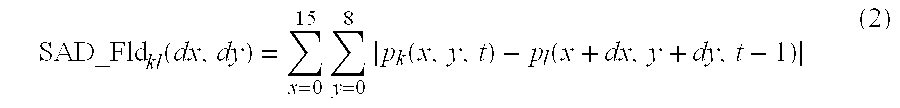
- where:
- SAD_Fld: Field SAD
- p k(x,y,t): pixel in the current field (either even (k=0) or odd field (k=1)).
- p l(x,y,t−1): pixel in the previous field (either even (l=0) or odd field (l=1))
- dx: displacement in the x-direction (x component of motion vector)
- dy: displacement in the y-direction (y component of motion vector)
- Thus, there are four patterns to drive the field predication, as listed below:
- Even field to even field (k=0, l=0)
- Even field to odd field (k=0, l=1)
- Odd field to even field (k=1, l=0)
- Odd field to odd field (k=1, l=1)
- In the prior art, after both frame based and field based motion estimation is complete, a decision is made on the mode of coding. This involves comparing the frame based motion estimation results with the best pair of field motion estimation results.
- In order to reduce the level of computation required to calculate both frame based and field based motion estimation, a preferred embodiment of the present invention is now described. In FIG. 4 there is illustrated a
method 30 for determining motion vectors in an interlaced video coding system for coding images comprising interlaced odd and even fields. As will be apparent to a person skilled in the art, the following terminology, where applicable, has the same meaning as the above terminology that refers to FIGS. 1a to 3 b. - After a
start step 31 themethod 30 effects a selectingstep 32 for selecting a current odd field block and a current even field block that respectively comprise odd and even fields of a selected current image block of a current image frame. An identifyingstep 33 then provides for identifying differences between the current odd field block and reference blocks in a first search window that is one of either an even field search window of even fields or an odd field search window of odd fields that combined form part of a reference image, and the differences between the current even field block and the reference blocks in a second search window that is the other one of the even field search window or odd field search window. For example, if the first search window is an odd field search window then the second search window will be an even field search window. Accordingly, the differences will be for odd field to odd field and even field to even field. Alternatively, if the first search window is an even field search window then the second search window will be an odd field search window. Accordingly, the differences will be for odd field to even field and even field to odd field. In this embodiment the differences are identified by SAD using a sub-sampled block matching as will be apparent to a person skilled in the art. - A determining
step 34 is effected for determining, from the differences in the identifyingstep 33, a suitable first odd field matching reference block for the current odd field block and a suitable first even field matching reference block for the current even field block. A providing reduced field search areas step 35 is then performed thereby providing, from the suitable first odd field matching reference block and suitable first even field matching reference block, respective reduced search areas in the even field search window and odd field search window. Typically, the reduced field search areas enclose their respective suitable first odd field matching reference block and suitable first even field matching reference block with a two pixel wide boundary. - A searching the reduced field search areas step 36 then searches the reduced search areas for identifying the differences between the current odd field block and the reference blocks in the second search window and identifying the differences between the current even field block and the reference blocks in the first search window.
- A determining second odd and even field matching reference blocks step 37 then determines, from the differences in
step 36, a suitable second odd field matching reference block for the current odd field block and a suitable second even field matching reference block for the current even field block. Then, a selecting field motion vectors step 38, provides for a respective motion vector for both the current odd field block and current even field block, the respective motion vector being based on relative motion between the current odd field block and either the first or second odd field matching reference block and relative motion between the current even field block and either the first or second even field matching reference block. - Further to the above, directly after the identifying
step 33 the method also effects the following steps starting with a determiningbest match step 39 for combined differences which is effected concurrently withstep 34. The combined differences being the corresponding differences (identified in step 33) of each corresponding odd field block and even field block that comprise a current image block. Hence, the determiningbest match step 39 determines a suitable pseudo-frame matching reference block for the corresponding current image block when compared with respective blocks having corresponding search window locations. - After completion of step 39 a providing reduced pseudo-frame search areas step 40 provides from the pseudo-frame matching reference block, reduced pseudo-frame search areas in the even field search window and odd field search window. Typically, the reduced pseudo-frame search areas enclose their respective pseudo-frame matching reference block by a two pixel wide boundary. A searching the reduced pseudo-frame search areas step 41 is then effected for identifying the pseudo-frame differences between the current odd field block and the reference blocks in both the first and second search window and identifying the differences between the current even field block and the reference blocks in the first and second search window. Thereafter, a determining
step 42 determines, from the pseudo-frame differences instep 41, the following: a suitable first pseudo-frame matching reference block from one reference block pair comprising a reference block in the even field search window for the current even field block and corresponding reference block in the odd field search window for the current odd field block; and a suitable second pseudo-frame matching reference block from another one reference block pair comprising a reference block in the odd field search window for the current even field block, and a corresponding reference block in the even field search window for the current odd field block, where each of reference block pair have corresponding search window locations. - A selecting a pseudo-frame
motion vector step 43 then selects a pseudo-frame motion vector from either the first or second pseudo-frame matching reference block. This is done by selecting the pseudo-frame matching reference block having the least differences. - A picking
step 44 is effected after bothstep step 44 picks a preferred motion vector from either the pseudo-frame motion vector or the respective field motion vector for both the current odd field block and current even field block. The preferred motion vector is picked by comparing the differences associated with the pseudo-frame motion vector with differences associated with the respective field motion vector for both the current odd field block and current even field block. As will be apparent to a person skilled in the art, SAD provides a count that identifies the differences. Thus, if the count value associated with the pseudo-frame motion vector have a count value of no more than 100 counts greater than the count value of the combined differences associated with the respective field motion vector for both the current odd field block and current even field block, then the preferred motion vector is the pseudo-frame motion vector. - Otherwise, the preferred motion vector is selected from the field motion vector for the current odd field block and current even field block that has the lowest count value.
- The
method 30 terminates at step 45 and will be repeated for generation of another motion vector for the current image. - Advantageously, the invention provides reduced search areas after determining a possible suitable block match associated with a potential motion vector. Also, the invention also allow for concurrent field and frame (pseudo-frame) motion vector determination.
- The detailed description provides preferred exemplary embodiments only, and is not intended to limit the scope, applicability, or configuration of the invention. Rather, the detailed description of the preferred exemplary embodiments provides those skilled in the art with an enabling description for implementing a preferred exemplary embodiment of the invention. It should be understood that various changes may be made in the function and arrangement of elements without departing from the spirit and scope of the invention as set forth in the appended claims.
Claims (7)
Priority Applications (3)
| Application Number | Priority Date | Filing Date | Title |
|---|---|---|---|
| US10/173,896 US6914938B2 (en) | 2002-06-18 | 2002-06-18 | Interlaced video motion estimation |
| AU2003234468A AU2003234468A1 (en) | 2002-06-18 | 2003-05-05 | Interlaced video motion estimation |
| PCT/US2003/013965 WO2003107648A2 (en) | 2002-06-18 | 2003-05-05 | Interlaced video motion estimation |
Applications Claiming Priority (1)
| Application Number | Priority Date | Filing Date | Title |
|---|---|---|---|
| US10/173,896 US6914938B2 (en) | 2002-06-18 | 2002-06-18 | Interlaced video motion estimation |
Publications (2)
| Publication Number | Publication Date |
|---|---|
| US20030231711A1 true US20030231711A1 (en) | 2003-12-18 |
| US6914938B2 US6914938B2 (en) | 2005-07-05 |
Family
ID=29733446
Family Applications (1)
| Application Number | Title | Priority Date | Filing Date |
|---|---|---|---|
| US10/173,896 Expired - Lifetime US6914938B2 (en) | 2002-06-18 | 2002-06-18 | Interlaced video motion estimation |
Country Status (3)
| Country | Link |
|---|---|
| US (1) | US6914938B2 (en) |
| AU (1) | AU2003234468A1 (en) |
| WO (1) | WO2003107648A2 (en) |
Cited By (13)
| Publication number | Priority date | Publication date | Assignee | Title |
|---|---|---|---|---|
| US20030123748A1 (en) * | 2001-10-29 | 2003-07-03 | Intel Corporation | Fast full search motion estimation with SIMD merge instruction |
| US20030131030A1 (en) * | 2001-10-29 | 2003-07-10 | Intel Corporation | Method and apparatus for parallel shift right merge of data |
| US20040054878A1 (en) * | 2001-10-29 | 2004-03-18 | Debes Eric L. | Method and apparatus for rearranging data between multiple registers |
| US20040054879A1 (en) * | 2001-10-29 | 2004-03-18 | Macy William W. | Method and apparatus for parallel table lookup using SIMD instructions |
| US20040098556A1 (en) * | 2001-10-29 | 2004-05-20 | Buxton Mark J. | Superior misaligned memory load and copy using merge hardware |
| US20040105495A1 (en) * | 2002-11-28 | 2004-06-03 | Heng-Kuan Lee | Experimental design for motion estimation |
| US20040133617A1 (en) * | 2001-10-29 | 2004-07-08 | Yen-Kuang Chen | Method and apparatus for computing matrix transformations |
| US20040210616A1 (en) * | 2001-10-29 | 2004-10-21 | Eric Debes | Method and apparatus for efficient integer transform |
| US20050108312A1 (en) * | 2001-10-29 | 2005-05-19 | Yen-Kuang Chen | Bitstream buffer manipulation with a SIMD merge instruction |
| US20060262860A1 (en) * | 2005-02-23 | 2006-11-23 | Chou Jim C | Macroblock adaptive frame/field coding architecture for scalable coding |
| US20070230573A1 (en) * | 2006-04-03 | 2007-10-04 | Matsushita Electric Industrial Co., Ltd. | Motion estimation device, motion estimation method, motion estimation integrated circuit, and picture coding device |
| US20090147848A1 (en) * | 2006-01-09 | 2009-06-11 | Lg Electronics Inc. | Inter-Layer Prediction Method for Video Signal |
| US20110029759A1 (en) * | 2001-10-29 | 2011-02-03 | Macy Jr William W | Method and apparatus for shuffling data |
Families Citing this family (5)
| Publication number | Priority date | Publication date | Assignee | Title |
|---|---|---|---|---|
| KR101200535B1 (en) * | 2006-01-12 | 2012-11-27 | (주)휴맥스 | Adaptive motion estimation/compensation device for MB-based illumination change and method thereof |
| JP5657391B2 (en) * | 2007-12-20 | 2015-01-21 | クゥアルコム・インコーポレイテッドQualcomm Incorporated | Image interpolation to reduce halo |
| JP5453304B2 (en) * | 2007-12-20 | 2014-03-26 | クゥアルコム・インコーポレイテッド | Motion estimation using adaptive search range |
| TWI475890B (en) * | 2008-10-14 | 2015-03-01 | Univ Nat Taiwan | High-performance block-matching vlsi architecture with low memory bandwidth for power-efficient multimedia devices |
| US8537283B2 (en) | 2010-04-15 | 2013-09-17 | Qualcomm Incorporated | High definition frame rate conversion |
Citations (4)
| Publication number | Priority date | Publication date | Assignee | Title |
|---|---|---|---|---|
| US5737023A (en) * | 1996-02-05 | 1998-04-07 | International Business Machines Corporation | Hierarchical motion estimation for interlaced video |
| US6078615A (en) * | 1993-03-31 | 2000-06-20 | Canon Kabushiki Kaisha | Encoding/decoding apparatus which performs an inverse orthogonal transformation on decoded data |
| US6147718A (en) * | 1994-08-25 | 2000-11-14 | Sony Corporation | Motion vector detection apparatus and predictive coding system for compensating for movement with the apparatus |
| US6560286B1 (en) * | 1999-12-29 | 2003-05-06 | Intel Corporation | Field frame motion design for digital video decoder |
-
2002
- 2002-06-18 US US10/173,896 patent/US6914938B2/en not_active Expired - Lifetime
-
2003
- 2003-05-05 WO PCT/US2003/013965 patent/WO2003107648A2/en not_active Application Discontinuation
- 2003-05-05 AU AU2003234468A patent/AU2003234468A1/en not_active Abandoned
Patent Citations (4)
| Publication number | Priority date | Publication date | Assignee | Title |
|---|---|---|---|---|
| US6078615A (en) * | 1993-03-31 | 2000-06-20 | Canon Kabushiki Kaisha | Encoding/decoding apparatus which performs an inverse orthogonal transformation on decoded data |
| US6147718A (en) * | 1994-08-25 | 2000-11-14 | Sony Corporation | Motion vector detection apparatus and predictive coding system for compensating for movement with the apparatus |
| US5737023A (en) * | 1996-02-05 | 1998-04-07 | International Business Machines Corporation | Hierarchical motion estimation for interlaced video |
| US6560286B1 (en) * | 1999-12-29 | 2003-05-06 | Intel Corporation | Field frame motion design for digital video decoder |
Cited By (65)
| Publication number | Priority date | Publication date | Assignee | Title |
|---|---|---|---|---|
| US9152420B2 (en) | 2001-10-29 | 2015-10-06 | Intel Corporation | Bitstream buffer manipulation with a SIMD merge instruction |
| US9170814B2 (en) | 2001-10-29 | 2015-10-27 | Intel Corporation | Bitstream buffer manipulation with a SIMD merge instruction |
| US20040054878A1 (en) * | 2001-10-29 | 2004-03-18 | Debes Eric L. | Method and apparatus for rearranging data between multiple registers |
| US20040054879A1 (en) * | 2001-10-29 | 2004-03-18 | Macy William W. | Method and apparatus for parallel table lookup using SIMD instructions |
| US20040098556A1 (en) * | 2001-10-29 | 2004-05-20 | Buxton Mark J. | Superior misaligned memory load and copy using merge hardware |
| US8214626B2 (en) | 2001-10-29 | 2012-07-03 | Intel Corporation | Method and apparatus for shuffling data |
| US20040133617A1 (en) * | 2001-10-29 | 2004-07-08 | Yen-Kuang Chen | Method and apparatus for computing matrix transformations |
| US20040210616A1 (en) * | 2001-10-29 | 2004-10-21 | Eric Debes | Method and apparatus for efficient integer transform |
| US20050108312A1 (en) * | 2001-10-29 | 2005-05-19 | Yen-Kuang Chen | Bitstream buffer manipulation with a SIMD merge instruction |
| US10732973B2 (en) | 2001-10-29 | 2020-08-04 | Intel Corporation | Processor to execute shift right merge instructions |
| US10152323B2 (en) | 2001-10-29 | 2018-12-11 | Intel Corporation | Method and apparatus for shuffling data |
| US7272622B2 (en) | 2001-10-29 | 2007-09-18 | Intel Corporation | Method and apparatus for parallel shift right merge of data |
| US10146541B2 (en) | 2001-10-29 | 2018-12-04 | Intel Corporation | Processor to execute shift right merge instructions |
| US8225075B2 (en) | 2001-10-29 | 2012-07-17 | Intel Corporation | Method and apparatus for shuffling data |
| US9477472B2 (en) | 2001-10-29 | 2016-10-25 | Intel Corporation | Method and apparatus for shuffling data |
| US9229718B2 (en) | 2001-10-29 | 2016-01-05 | Intel Corporation | Method and apparatus for shuffling data |
| US9229719B2 (en) | 2001-10-29 | 2016-01-05 | Intel Corporation | Method and apparatus for shuffling data |
| US9218184B2 (en) | 2001-10-29 | 2015-12-22 | Intel Corporation | Processor to execute shift right merge instructions |
| US9189237B2 (en) | 2001-10-29 | 2015-11-17 | Intel Corporation | Bitstream buffer manipulation with a SIMD merge instruction |
| US9189238B2 (en) | 2001-10-29 | 2015-11-17 | Intel Corporation | Bitstream buffer manipulation with a SIMD merge instruction |
| US7624138B2 (en) | 2001-10-29 | 2009-11-24 | Intel Corporation | Method and apparatus for efficient integer transform |
| US7631025B2 (en) | 2001-10-29 | 2009-12-08 | Intel Corporation | Method and apparatus for rearranging data between multiple registers |
| US20100011042A1 (en) * | 2001-10-29 | 2010-01-14 | Eric Debes | Method and Apparatus for Efficient Integer Transform |
| US9182985B2 (en) | 2001-10-29 | 2015-11-10 | Intel Corporation | Bitstream buffer manipulation with a SIMD merge instruction |
| US7685212B2 (en) * | 2001-10-29 | 2010-03-23 | Intel Corporation | Fast full search motion estimation with SIMD merge instruction |
| US9182988B2 (en) | 2001-10-29 | 2015-11-10 | Intel Corporation | Bitstream buffer manipulation with a SIMD merge instruction |
| US7739319B2 (en) | 2001-10-29 | 2010-06-15 | Intel Corporation | Method and apparatus for parallel table lookup using SIMD instructions |
| US7818356B2 (en) | 2001-10-29 | 2010-10-19 | Intel Corporation | Bitstream buffer manipulation with a SIMD merge instruction |
| US9182987B2 (en) | 2001-10-29 | 2015-11-10 | Intel Corporation | Bitstream buffer manipulation with a SIMD merge instruction |
| US20110029759A1 (en) * | 2001-10-29 | 2011-02-03 | Macy Jr William W | Method and apparatus for shuffling data |
| US20110035426A1 (en) * | 2001-10-29 | 2011-02-10 | Yen-Kuang Chen | Bitstream Buffer Manipulation with a SIMD Merge Instruction |
| US9170815B2 (en) | 2001-10-29 | 2015-10-27 | Intel Corporation | Bitstream buffer manipulation with a SIMD merge instruction |
| US20030131030A1 (en) * | 2001-10-29 | 2003-07-10 | Intel Corporation | Method and apparatus for parallel shift right merge of data |
| US7340495B2 (en) | 2001-10-29 | 2008-03-04 | Intel Corporation | Superior misaligned memory load and copy using merge hardware |
| US7725521B2 (en) | 2001-10-29 | 2010-05-25 | Intel Corporation | Method and apparatus for computing matrix transformations |
| US8346838B2 (en) | 2001-10-29 | 2013-01-01 | Intel Corporation | Method and apparatus for efficient integer transform |
| US20030123748A1 (en) * | 2001-10-29 | 2003-07-03 | Intel Corporation | Fast full search motion estimation with SIMD merge instruction |
| US8782377B2 (en) | 2001-10-29 | 2014-07-15 | Intel Corporation | Processor to execute shift right merge instructions |
| US8745358B2 (en) | 2001-10-29 | 2014-06-03 | Intel Corporation | Processor to execute shift right merge instructions |
| US8688959B2 (en) | 2001-10-29 | 2014-04-01 | Intel Corporation | Method and apparatus for shuffling data |
| US8510355B2 (en) | 2001-10-29 | 2013-08-13 | Intel Corporation | Bitstream buffer manipulation with a SIMD merge instruction |
| US20040105495A1 (en) * | 2002-11-28 | 2004-06-03 | Heng-Kuan Lee | Experimental design for motion estimation |
| US6993077B2 (en) * | 2002-11-28 | 2006-01-31 | Faraday Technology Corp. | Experimental design for motion estimation |
| US20060262860A1 (en) * | 2005-02-23 | 2006-11-23 | Chou Jim C | Macroblock adaptive frame/field coding architecture for scalable coding |
| US8457201B2 (en) | 2006-01-09 | 2013-06-04 | Lg Electronics Inc. | Inter-layer prediction method for video signal |
| US20090220008A1 (en) * | 2006-01-09 | 2009-09-03 | Seung Wook Park | Inter-Layer Prediction Method for Video Signal |
| US8451899B2 (en) | 2006-01-09 | 2013-05-28 | Lg Electronics Inc. | Inter-layer prediction method for video signal |
| US20100061456A1 (en) * | 2006-01-09 | 2010-03-11 | Seung Wook Park | Inter-Layer Prediction Method for Video Signal |
| US8792554B2 (en) | 2006-01-09 | 2014-07-29 | Lg Electronics Inc. | Inter-layer prediction method for video signal |
| US8345755B2 (en) * | 2006-01-09 | 2013-01-01 | Lg Electronics, Inc. | Inter-layer prediction method for video signal |
| US8264968B2 (en) | 2006-01-09 | 2012-09-11 | Lg Electronics Inc. | Inter-layer prediction method for video signal |
| US20100316124A1 (en) * | 2006-01-09 | 2010-12-16 | Lg Electronics Inc. | Inter-layer prediction method for video signal |
| US8494042B2 (en) | 2006-01-09 | 2013-07-23 | Lg Electronics Inc. | Inter-layer prediction method for video signal |
| US8494060B2 (en) | 2006-01-09 | 2013-07-23 | Lg Electronics Inc. | Inter-layer prediction method for video signal |
| US8401091B2 (en) | 2006-01-09 | 2013-03-19 | Lg Electronics Inc. | Inter-layer prediction method for video signal |
| US8687688B2 (en) | 2006-01-09 | 2014-04-01 | Lg Electronics, Inc. | Inter-layer prediction method for video signal |
| US20090220000A1 (en) * | 2006-01-09 | 2009-09-03 | Lg Electronics Inc. | Inter-Layer Prediction Method for Video Signal |
| US20090180537A1 (en) * | 2006-01-09 | 2009-07-16 | Seung Wook Park | Inter-Layer Prediction Method for Video Signal |
| US20090175359A1 (en) * | 2006-01-09 | 2009-07-09 | Byeong Moon Jeon | Inter-Layer Prediction Method For Video Signal |
| US20090168875A1 (en) * | 2006-01-09 | 2009-07-02 | Seung Wook Park | Inter-Layer Prediction Method for Video Signal |
| US20090147848A1 (en) * | 2006-01-09 | 2009-06-11 | Lg Electronics Inc. | Inter-Layer Prediction Method for Video Signal |
| US9497453B2 (en) | 2006-01-09 | 2016-11-15 | Lg Electronics Inc. | Inter-layer prediction method for video signal |
| US8619872B2 (en) | 2006-01-09 | 2013-12-31 | Lg Electronics, Inc. | Inter-layer prediction method for video signal |
| US20070230573A1 (en) * | 2006-04-03 | 2007-10-04 | Matsushita Electric Industrial Co., Ltd. | Motion estimation device, motion estimation method, motion estimation integrated circuit, and picture coding device |
| US8208541B2 (en) * | 2006-04-03 | 2012-06-26 | Panasonic Corporation | Motion estimation device, motion estimation method, motion estimation integrated circuit, and picture coding device |
Also Published As
| Publication number | Publication date |
|---|---|
| AU2003234468A8 (en) | 2003-12-31 |
| AU2003234468A1 (en) | 2003-12-31 |
| WO2003107648A3 (en) | 2004-02-19 |
| WO2003107648A2 (en) | 2003-12-24 |
| US6914938B2 (en) | 2005-07-05 |
Similar Documents
| Publication | Publication Date | Title |
|---|---|---|
| US6449312B1 (en) | Method of estimating motion in interlaced video | |
| US6914938B2 (en) | Interlaced video motion estimation | |
| US6782054B2 (en) | Method and apparatus for motion vector estimation | |
| Nam et al. | A fast hierarchical motion vector estimation algorithm using mean pyramid | |
| US6175593B1 (en) | Method for estimating motion vector in moving picture | |
| US8130835B2 (en) | Method and apparatus for generating motion vector in hierarchical motion estimation | |
| US6381277B1 (en) | Shaped information coding device for interlaced scanning video and method therefor | |
| US6671319B1 (en) | Methods and apparatus for motion estimation using neighboring macroblocks | |
| US7099392B2 (en) | Motion vector searching method using plural search areas | |
| US6483876B1 (en) | Methods and apparatus for reduction of prediction modes in motion estimation | |
| EP1430724B1 (en) | Motion estimation and/or compensation | |
| US7321626B2 (en) | System and method for predictive motion estimation using a global motion predictor | |
| US20070183504A1 (en) | Motion estimation using prediction guided decimated search | |
| EP0637894A2 (en) | Apparatus and method for detecting motion vectors to half-pixel accuracy | |
| US6317460B1 (en) | Motion vector generation by temporal interpolation | |
| Wu et al. | Joint estimation of forward and backward motion vectors for interpolative prediction of video | |
| US20050213828A1 (en) | Motion estimation or P-type images using direct mode prediction | |
| JP2005505841A (en) | Apparatus and method for motion estimation | |
| US6996175B1 (en) | Motion vector estimation | |
| US6823012B2 (en) | Method and system for estimating motion vector at high speed for low bit-rate coding | |
| US20030067988A1 (en) | Fast half-pixel motion estimation using steepest descent | |
| US20080187050A1 (en) | Frame interpolation apparatus and method for motion estimation through separation into static object and moving object | |
| Namuduri | Motion estimation using spatio-temporal contextual information | |
| EP1295483B1 (en) | Method of performing motion estimation | |
| EP1420595B1 (en) | Motion vector selection in a video motion estimator based on a preferred reference point |
Legal Events
| Date | Code | Title | Description |
|---|---|---|---|
| AS | Assignment |
Owner name: MOTOROLA, INC., ILLINOIS Free format text: ASSIGNMENT OF ASSIGNORS INTEREST;ASSIGNORS:ZHANG, JIAN;MATHEW, REJI;ZHANG, XING;REEL/FRAME:013023/0007 Effective date: 20020523 |
|
| STCF | Information on status: patent grant |
Free format text: PATENTED CASE |
|
| FPAY | Fee payment |
Year of fee payment: 4 |
|
| AS | Assignment |
Owner name: MOTOROLA MOBILITY, INC, ILLINOIS Free format text: ASSIGNMENT OF ASSIGNORS INTEREST;ASSIGNOR:MOTOROLA, INC;REEL/FRAME:025673/0558 Effective date: 20100731 |
|
| AS | Assignment |
Owner name: MOTOROLA MOBILITY LLC, ILLINOIS Free format text: CHANGE OF NAME;ASSIGNOR:MOTOROLA MOBILITY, INC.;REEL/FRAME:029216/0282 Effective date: 20120622 |
|
| FPAY | Fee payment |
Year of fee payment: 8 |
|
| AS | Assignment |
Owner name: GOOGLE TECHNOLOGY HOLDINGS LLC, CALIFORNIA Free format text: ASSIGNMENT OF ASSIGNORS INTEREST;ASSIGNOR:MOTOROLA MOBILITY LLC;REEL/FRAME:034430/0001 Effective date: 20141028 |
|
| FPAY | Fee payment |
Year of fee payment: 12 |