US20030197927A1 - Slide for a microscopic examination of biological fluid - Google Patents
Slide for a microscopic examination of biological fluid Download PDFInfo
- Publication number
- US20030197927A1 US20030197927A1 US10/442,879 US44287903A US2003197927A1 US 20030197927 A1 US20030197927 A1 US 20030197927A1 US 44287903 A US44287903 A US 44287903A US 2003197927 A1 US2003197927 A1 US 2003197927A1
- Authority
- US
- United States
- Prior art keywords
- computation
- relief
- chamber
- lateral wall
- floor
- Prior art date
- Legal status (The legal status is an assumption and is not a legal conclusion. Google has not performed a legal analysis and makes no representation as to the accuracy of the status listed.)
- Abandoned
Links
Images


Classifications
-
- B—PERFORMING OPERATIONS; TRANSPORTING
- B01—PHYSICAL OR CHEMICAL PROCESSES OR APPARATUS IN GENERAL
- B01L—CHEMICAL OR PHYSICAL LABORATORY APPARATUS FOR GENERAL USE
- B01L3/00—Containers or dishes for laboratory use, e.g. laboratory glassware; Droppers
- B01L3/50—Containers for the purpose of retaining a material to be analysed, e.g. test tubes
- B01L3/508—Containers for the purpose of retaining a material to be analysed, e.g. test tubes rigid containers not provided for above
- B01L3/5085—Containers for the purpose of retaining a material to be analysed, e.g. test tubes rigid containers not provided for above for multiple samples, e.g. microtitration plates
-
- G—PHYSICS
- G02—OPTICS
- G02B—OPTICAL ELEMENTS, SYSTEMS OR APPARATUS
- G02B21/00—Microscopes
- G02B21/34—Microscope slides, e.g. mounting specimens on microscope slides
-
- B—PERFORMING OPERATIONS; TRANSPORTING
- B01—PHYSICAL OR CHEMICAL PROCESSES OR APPARATUS IN GENERAL
- B01L—CHEMICAL OR PHYSICAL LABORATORY APPARATUS FOR GENERAL USE
- B01L2400/00—Moving or stopping fluids
- B01L2400/04—Moving fluids with specific forces or mechanical means
- B01L2400/0403—Moving fluids with specific forces or mechanical means specific forces
- B01L2400/0406—Moving fluids with specific forces or mechanical means specific forces capillary forces
Definitions
- This invention relates to slides for use in microscopic examination of biological fluid.
- slides have been used in the microscopic examination of biological fluid, such as urine, blood, and spinal fluid, for the purpose of carrying out a computation of elements present in a predefined sample.
- the slides are constituted by two plates of transparent plastic material, one for a floor and one for a covering, which define a plurality of wells in their interiors.
- the wells are filled by capillarity with drops of the biological fluid which are deposited on the slide itself.
- computation chambers On the floor of each well are formed computation chambers, in each of which is contained an accurate volume of biological fluid to be examined. These computation chambers are obtained by means of reliefs which are formed from the floor of the well towards the covering or roof.
- the European Patent Publication No. 326,349 A2 describes a slide made of plastic material in which computation chambers in wells are defined by a grid pattern made up of symmetrical lines.
- the symmetrical lines have a width of between about 0.008 mm and 0.05 mm, and extend upwardly from the floor of the well preferably for 0.008 mm and the minimal area for the reading of each chamber has a floor of 0.111 mm.
- the slides produced by the company Kima have reliefs of a width between 0.005 mm and 0.05 mm.
- the relief forms a circular computation chamber having as the floor a circle of internal diameter 0.376 mm.
- the reliefs or grids define computation chambers, preferably arranged 3 ⁇ 3 , and the total internal surface of all the chambers is 1 mm 2 .
- the production of these types of slides from plastic material requires the use of molds provided with engraved marks and impressions which are of microscopic value, well defined, and made by means of special machines for the removal of chips, by electroerosion, or with other processes known in the art.
- the present invention relates to slides in which computation chambers present in wells are defined by reliefs which protrude from the bottom of the chambers.
- the reliefs are preferably rectilinear or circular—a profile easily achievable with machines.
- the reliefs define precise lateral walls of the computation chamber so as to measure accurately the volume of the chamber.
- the invention provides slides comprising reliefs defining computation chambers which are sectioned along a plane perpendicular to the bottom of the well.
- the relief has a section with a profile shaped as a polygon having at least one right angle. The right angle is defined by the bottom of the computation chamber and the internal lateral wall of the computation chamber.
- the invention further provides that the lateral wall of the computation chamber has its upper extremity constituted by a corner which is a part of the polygon which defines the relief.
- the lateral wall has an internal angular opening of 90 degrees at the most and is rounded with a radius of curvature at the most 0.002 mm.
- the preferred form of the reliefs has a rectangular trapezium or a rectangular triangle section.
- the embodiments essentially better define the separation between the area which constitutes the computation chamber and the surrounding area which separates reciprocally the plurality of the chambers.
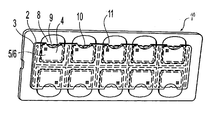
- FIG. 1 shows a perspective view of the entire slide according to the present invention
- FIG. 2 shows a matrix of nine computation chambers, disposed 3 ⁇ 3;
- FIG. 3A shows a plan view of a computation chamber defined by a relief having a section in the shape of a rectangular trapezium
- FIG. 3B is a cross-sectional view along line III-III of FIG. 3A of a computation chamber defined by a relief having a section in the shape of a rectangular trapezium;
- FIG. 3C is a detailed view of a computation chamber defined by a relief having a section in the shape of a rectangular trapezium;
- FIG. 4A shows a plan view of a computation chamber defined by a relief having a section in the shape of a rectangular trapezium
- FIG. 4B is a cross-sectional view along line IV-IV of FIG. 4A of a computation chamber defined by a relief having a section in the shape of a right triangle;
- FIG. 4C is a detailed view of a computation chamber defined by a relief having a section in the shape of a right triangle;
- FIG. 5A shows a detailed view of the upper extremity of the internal lateral wall of the computation chamber of FIG. 3C.
- FIG. 5B shows a detailed view of the upper extremity of the internal lateral wall of the computation chamber of FIG. 4C.
- a slide ( 1 ) made of plastic material comprises a lower plate ( 2 ) and an upper plate ( 3 ), the lower plate being assembled with the upper plate ( 3 ) preferably by ultrasonic welding.
- wells ( 4 ) which are each constituted by a floor ( 5 ) which is a part of the lower plate perfectly planar and smooth, with a grade of roughness which should be the lowest possible and a roof ( 6 ) which is defined by the upper plate ( 3 ) with such characteristics of transparency to provide optimal microscopic observation.
- Each well is filled with a drop of a sample of biological fluid which is deposited on a threshold ( 8 ) which is formed on the lower plate.
- the fluid penetrates into the well ( 4 ) by capillarity through an opening ( 9 ).
- each well ( 4 ) has an area of about 66 mm 2 and contains a volume equal to 6.6 mm 3 .
- a matrix ( 10 ) constituted by nine computation chambers ( 1 ) disposed in series of 3 ⁇ 3.
- Each computation chamber ( 11 ) is constituted by a circle of internal diameter 0.376 mm.
- the chamber is delimited by a relief ( 12 ).
- Each relief is characterized in that it has a section with a profile shaped as a polygon. Such shape may be a rectangular (or right) trapezium, as shown in FIG. 3, or a right triangle, as shown in FIG. 4.
- the side of the right angle of the polygonal shape constitutes an internal vertical or lateral wall ( 13 ) of the chamber.
- the relief of the present invention is preferably rectilinear or circular, which has a profile easily achievable with machines. Accordingly, the invention provides a relief defining a computation chamber which is sectioned along a plane perpendicular to the bottom of the well. The relief has a section of a polygon having at least one right angle. The right angle is defined by the floor of the chamber and the internal lateral wall of the chamber. The relief defines a precise lateral wall of the computation chamber so as to measure accurately the volume of the chamber.
- the preferred form of the reliefs has a rectangular (or right) trapezium or a right triangle section.
- the embodiment essentially better defines the separation between the areas of the computation chamber and the surrounding area which separates reciprocally the plurality of the chambers.
- the invention provides that the lateral wall of the computation chamber has its upper extremity constituted by a corner which is a part of the polygon which defines the relief.
- the lateral wall has an internal angular opening of 90 degrees at the most and the apex is rounded with a radius of curvature at the most 0.002 mm, as shown in FIGS. 5A and 5B as references A and B, respectively.
Abstract
A slide for use in microscopic examination of biological fluid is constituted by two plates of transparent material, one plate being a bottom and the other plate being a cover, the plates forming wells which are filled by capillarity with the biological fluid to be examined. A plurality of reliefs form a plurality of computation chambers in each well. The reliefs which define each computation chamber sectioned along a plane perpendicular to the bottom of the well have a shaped section along a profile assimilable to a polygon having at least one right angle.
Description
- This application is a continuation of Ser. No. 09/918,274, filed Jul. 30, 2001, which is hereby incorporated by reference herein in its entirety.
- This invention relates to slides for use in microscopic examination of biological fluid.
- It is known that plates, called slides, have been used in the microscopic examination of biological fluid, such as urine, blood, and spinal fluid, for the purpose of carrying out a computation of elements present in a predefined sample. The slides are constituted by two plates of transparent plastic material, one for a floor and one for a covering, which define a plurality of wells in their interiors. The wells are filled by capillarity with drops of the biological fluid which are deposited on the slide itself.
- On the floor of each well are formed computation chambers, in each of which is contained an accurate volume of biological fluid to be examined. These computation chambers are obtained by means of reliefs which are formed from the floor of the well towards the covering or roof.
- In reference to the trajectory of the reliefs it is possible to obtain quadrilateral or circular computation chambers, depending on whether the reliefs have a rectilinear direction so as to form grids or have a circular direction so as to form circles which are reciprocally separated. By way of example of the first type of computation chamber, the European Patent Publication No. 326,349 A2 describes a slide made of plastic material in which computation chambers in wells are defined by a grid pattern made up of symmetrical lines. The symmetrical lines have a width of between about 0.008 mm and 0.05 mm, and extend upwardly from the floor of the well preferably for 0.008 mm and the minimal area for the reading of each chamber has a floor of 0.111 mm.
- Also by way of example, with respect to the second type of a computation chamber, the slides produced by the company Kima have reliefs of a width between 0.005 mm and 0.05 mm. The relief forms a circular computation chamber having as the floor a circle of internal diameter 0.376 mm.
- The reliefs or grids define computation chambers, preferably arranged 3×3, and the total internal surface of all the chambers is 1 mm2. In order to obtain reliefs of millesimal dimensions, the production of these types of slides from plastic material requires the use of molds provided with engraved marks and impressions which are of microscopic value, well defined, and made by means of special machines for the removal of chips, by electroerosion, or with other processes known in the art.
- In fact, by means of constructions known up to the present, observations with an optical microscope for measuring small particles in a fluid sample are often inaccurate, because in conventional reliefs the optical lines which correspond respectively to the line of the vertex and to the line of the bottom of the relief are subject to confusion due to the inclination of the wall of the relief.
- This fact causes an error in the reading or in the computation of small particles because it is difficult to examine the small particles which remain adhering to the inclined walls. There is also a discrepancy in reading the values of areas measured on the upper plane of the computation chamber (corresponding to the relief), and areas measured a the bottom of the computation chamber. This error is further increased due to the fact that it has heretofore been impossible to provide reliefs with inclined walls which are perfectly uniform along the entire computation chamber.
- The present invention relates to slides in which computation chambers present in wells are defined by reliefs which protrude from the bottom of the chambers. The reliefs are preferably rectilinear or circular—a profile easily achievable with machines. The reliefs define precise lateral walls of the computation chamber so as to measure accurately the volume of the chamber.
- The invention provides slides comprising reliefs defining computation chambers which are sectioned along a plane perpendicular to the bottom of the well. The relief has a section with a profile shaped as a polygon having at least one right angle. The right angle is defined by the bottom of the computation chamber and the internal lateral wall of the computation chamber.
- The invention further provides that the lateral wall of the computation chamber has its upper extremity constituted by a corner which is a part of the polygon which defines the relief. The lateral wall has an internal angular opening of 90 degrees at the most and is rounded with a radius of curvature at the most 0.002 mm.
- In operation, the preferred form of the reliefs has a rectangular trapezium or a rectangular triangle section. The embodiments essentially better define the separation between the area which constitutes the computation chamber and the surrounding area which separates reciprocally the plurality of the chambers.
- The characteristics of the invention will be better clarified by reference to a description of a possible embodiment. The embodiment is provided by way of illustration of a non-limiting example, as described in the figures, of which:
- FIG. 1 shows a perspective view of the entire slide according to the present invention;
- FIG. 2 shows a matrix of nine computation chambers, disposed 3×3;
- FIG. 3A shows a plan view of a computation chamber defined by a relief having a section in the shape of a rectangular trapezium;
- FIG. 3B is a cross-sectional view along line III-III of FIG. 3A of a computation chamber defined by a relief having a section in the shape of a rectangular trapezium;
- FIG. 3C is a detailed view of a computation chamber defined by a relief having a section in the shape of a rectangular trapezium;
- FIG. 4A shows a plan view of a computation chamber defined by a relief having a section in the shape of a rectangular trapezium;
- FIG. 4B is a cross-sectional view along line IV-IV of FIG. 4A of a computation chamber defined by a relief having a section in the shape of a right triangle;
- FIG. 4C is a detailed view of a computation chamber defined by a relief having a section in the shape of a right triangle;
- FIG. 5A shows a detailed view of the upper extremity of the internal lateral wall of the computation chamber of FIG. 3C; and
- FIG. 5B shows a detailed view of the upper extremity of the internal lateral wall of the computation chamber of FIG. 4C.
- As shown in FIG. 1, a slide ( 1) made of plastic material comprises a lower plate (2) and an upper plate (3), the lower plate being assembled with the upper plate (3) preferably by ultrasonic welding. After these two plates are assembled, they define wells (4), which are each constituted by a floor (5) which is a part of the lower plate perfectly planar and smooth, with a grade of roughness which should be the lowest possible and a roof (6) which is defined by the upper plate (3) with such characteristics of transparency to provide optimal microscopic observation.
- Each well is filled with a drop of a sample of biological fluid which is deposited on a threshold ( 8) which is formed on the lower plate. The fluid penetrates into the well (4) by capillarity through an opening (9).
- In the described configuration, each well ( 4) has an area of about 66 mm2 and contains a volume equal to 6.6 mm3. At the bottom of each well (4) is present a matrix (10) constituted by nine computation chambers (1) disposed in series of 3×3. Each computation chamber (11) is constituted by a circle of internal diameter 0.376 mm. The chamber is delimited by a relief (12). Each relief is characterized in that it has a section with a profile shaped as a polygon. Such shape may be a rectangular (or right) trapezium, as shown in FIG. 3, or a right triangle, as shown in FIG. 4. The side of the right angle of the polygonal shape constitutes an internal vertical or lateral wall (13) of the chamber.
- The relief of the present invention is preferably rectilinear or circular, which has a profile easily achievable with machines. Accordingly, the invention provides a relief defining a computation chamber which is sectioned along a plane perpendicular to the bottom of the well. The relief has a section of a polygon having at least one right angle. The right angle is defined by the floor of the chamber and the internal lateral wall of the chamber. The relief defines a precise lateral wall of the computation chamber so as to measure accurately the volume of the chamber.
- In operation, the preferred form of the reliefs has a rectangular (or right) trapezium or a right triangle section. The embodiment essentially better defines the separation between the areas of the computation chamber and the surrounding area which separates reciprocally the plurality of the chambers.
- Further, the invention provides that the lateral wall of the computation chamber has its upper extremity constituted by a corner which is a part of the polygon which defines the relief. The lateral wall has an internal angular opening of 90 degrees at the most and the apex is rounded with a radius of curvature at the most 0.002 mm, as shown in FIGS. 5A and 5B as references A and B, respectively.
- Obviously some embodiments are different from the embodiment which has been described above, in forms, dimensions, the number of the wells, the number of computation chambers present in each well, or in the use of material, for instance, a material which is not plastic, such as glass, but technically equivalent may be used. Such modifications are also intended to fall within the scope of the appended claims.
Claims (15)
1. A slide for use in microscopic examination of biological fluid for a computation of elements in a predefined sample, said slide comprising:
a first plate and a second plate of transparent material, said first plate forming a floor and said second plate forming a covering, said plates forming there between at least one well with a bottom; and
a computation chamber defined by a relief extending upwardly from said bottom of said well, said computation chamber having a floor;
wherein:
said relief has an internal lateral wall facing said computation chamber and extending from said floor to the upper extremity of said relief; and
said floor of said computation chamber and said internal lateral wall of said computation chamber substantially define a right angle.
2. The slide according to claim 1 , wherein said relief has a cross-section shaped as a polygon.
3. The slide according to claim 2 , wherein said internal lateral wall of said computation chamber has a corner at its upper extremity with a radius of curvature of at most 0.002 mm.
4. The slide according to claim 3 , wherein said floor of said computation chamber and said internal lateral wall form an angle of said polygon of at most 90°.
5. The slide according to claim 1 , wherein said computation chamber has a substantially quadrilateral shape.
6. The slide according to claim 1 , wherein said computation chamber has a substantially circular shape.
7. The slide according to claim 1 , wherein said relief has a cross-section approximately in the shape of a rectangular trapezium.
8. The slide according to claim 1 , wherein said relief has a cross-section approximately in the shape of a right triangle.
9. A slide for use in microscopic examination of biological fluid for a computation of elements in a predefined sample, said slide comprising:
a first plate and a second plate of transparent material, said first plate forming a floor and said second plate forming a covering, said plates forming therebetween at least one well with a bottom; and
a computation chamber formed on said bottom of said well and having a floor, said computation chamber being defined by a relief extending from said bottom of said well, said relief having a side defining an internal lateral wall of said computation chamber;
wherein the entire internal lateral wall of said computation chamber is substantially at a right angle with respect to said floor of said computation chamber.
10. The slide according to claim 9 , wherein:
said relief has a cross-section shaped as a rectangular trapezium; and
said internal lateral wall of said computation chamber forms the side of the right angle of the rectangular trapezium.
11. The slide according to claim 9 , wherein:
said relief has a cross-section shaped as a right triangle; and
said internal lateral wall of said computation chamber forms the side of the right angle of the right triangle.
12. The slide according to claim 9 , wherein the top of said internal lateral wall is rounded with a radius of curvature of at most 0.002 mm.
13. The slide according to claim 9 , wherein:
said relief has a cross-section shaped as a polygon with at least one right angle defined by said floor of said computation chamber and said internal lateral wall of said computation chamber.
14. The slide according to claim 9 , wherein said relief extends rectilinearly, whereby said computation chamber has a substantially quadrilateral shape.
15. The slide according to claim 9 , wherein said relief extends circularly, whereby said computation chamber has a substantially circular shape.
Priority Applications (1)
| Application Number | Priority Date | Filing Date | Title |
|---|---|---|---|
| US10/442,879 US20030197927A1 (en) | 2001-01-12 | 2003-05-21 | Slide for a microscopic examination of biological fluid |
Applications Claiming Priority (4)
| Application Number | Priority Date | Filing Date | Title |
|---|---|---|---|
| IT2001VI000014A ITVI20010014A1 (en) | 2001-01-12 | 2001-01-12 | SLIDE FOR THE MICROSCOPIC EXAMINATION OF BIOLOGICAL LIQUIDS |
| ITVI2001A000014 | 2001-01-12 | ||
| US09/918,275 US6594077B2 (en) | 2001-01-12 | 2001-07-30 | Slide for the microscopic examination of biological fluids |
| US10/442,879 US20030197927A1 (en) | 2001-01-12 | 2003-05-21 | Slide for a microscopic examination of biological fluid |
Related Parent Applications (1)
| Application Number | Title | Priority Date | Filing Date |
|---|---|---|---|
| US09/918,275 Continuation US6594077B2 (en) | 2001-01-12 | 2001-07-30 | Slide for the microscopic examination of biological fluids |
Publications (1)
| Publication Number | Publication Date |
|---|---|
| US20030197927A1 true US20030197927A1 (en) | 2003-10-23 |
Family
ID=11461490
Family Applications (2)
| Application Number | Title | Priority Date | Filing Date |
|---|---|---|---|
| US09/918,275 Expired - Fee Related US6594077B2 (en) | 2001-01-12 | 2001-07-30 | Slide for the microscopic examination of biological fluids |
| US10/442,879 Abandoned US20030197927A1 (en) | 2001-01-12 | 2003-05-21 | Slide for a microscopic examination of biological fluid |
Family Applications Before (1)
| Application Number | Title | Priority Date | Filing Date |
|---|---|---|---|
| US09/918,275 Expired - Fee Related US6594077B2 (en) | 2001-01-12 | 2001-07-30 | Slide for the microscopic examination of biological fluids |
Country Status (2)
| Country | Link |
|---|---|
| US (2) | US6594077B2 (en) |
| IT (1) | ITVI20010014A1 (en) |
Families Citing this family (4)
| Publication number | Priority date | Publication date | Assignee | Title |
|---|---|---|---|---|
| ITVI20010014A1 (en) * | 2001-01-12 | 2002-07-12 | Meus Srl | SLIDE FOR THE MICROSCOPIC EXAMINATION OF BIOLOGICAL LIQUIDS |
| TW587694U (en) * | 2003-03-14 | 2004-05-11 | Mau-Guei Jang | Protruded platform type quantitative cell counter plate |
| US20090155840A1 (en) * | 2007-12-17 | 2009-06-18 | Beebe David J | Method and device for cell counting |
| CN104130940B (en) * | 2014-07-28 | 2016-03-30 | 河南科技大学 | A kind of Micro-Organism Culture Dish |
Citations (8)
| Publication number | Priority date | Publication date | Assignee | Title |
|---|---|---|---|---|
| US3572892A (en) * | 1969-02-10 | 1971-03-30 | Richardson Merrell Inc | Multiple well tissue culture slide |
| US4441793A (en) * | 1983-01-10 | 1984-04-10 | Elkins Carlos D | Microscopic evaluation slide |
| US4589743A (en) * | 1985-03-08 | 1986-05-20 | Clegg John E | Circular microscope specimen slide |
| US4607921A (en) * | 1982-09-20 | 1986-08-26 | V-Tech, Inc. | Wet mount microscopic examination slide II |
| US4637693A (en) * | 1985-07-23 | 1987-01-20 | Icl Scientific Corp. | Microscope inspection slide |
| US4790640A (en) * | 1985-10-11 | 1988-12-13 | Nason Frederic L | Laboratory slide |
| US20030107731A1 (en) * | 2000-01-28 | 2003-06-12 | De Kock Alfons Petrus Antonius Gerrit | Counting chamber provided with reference and method for manufacturing a counting chamber provided with a reference |
| US6594077B2 (en) * | 2001-01-12 | 2003-07-15 | Meus S.R.L. | Slide for the microscopic examination of biological fluids |
Family Cites Families (1)
| Publication number | Priority date | Publication date | Assignee | Title |
|---|---|---|---|---|
| DE68904080T2 (en) * | 1988-01-27 | 1993-06-17 | Hycor Biomedical | STRUCTURED OPTICAL PLASTIC COMPONENTS. |
-
2001
- 2001-01-12 IT IT2001VI000014A patent/ITVI20010014A1/en unknown
- 2001-07-30 US US09/918,275 patent/US6594077B2/en not_active Expired - Fee Related
-
2003
- 2003-05-21 US US10/442,879 patent/US20030197927A1/en not_active Abandoned
Patent Citations (8)
| Publication number | Priority date | Publication date | Assignee | Title |
|---|---|---|---|---|
| US3572892A (en) * | 1969-02-10 | 1971-03-30 | Richardson Merrell Inc | Multiple well tissue culture slide |
| US4607921A (en) * | 1982-09-20 | 1986-08-26 | V-Tech, Inc. | Wet mount microscopic examination slide II |
| US4441793A (en) * | 1983-01-10 | 1984-04-10 | Elkins Carlos D | Microscopic evaluation slide |
| US4589743A (en) * | 1985-03-08 | 1986-05-20 | Clegg John E | Circular microscope specimen slide |
| US4637693A (en) * | 1985-07-23 | 1987-01-20 | Icl Scientific Corp. | Microscope inspection slide |
| US4790640A (en) * | 1985-10-11 | 1988-12-13 | Nason Frederic L | Laboratory slide |
| US20030107731A1 (en) * | 2000-01-28 | 2003-06-12 | De Kock Alfons Petrus Antonius Gerrit | Counting chamber provided with reference and method for manufacturing a counting chamber provided with a reference |
| US6594077B2 (en) * | 2001-01-12 | 2003-07-15 | Meus S.R.L. | Slide for the microscopic examination of biological fluids |
Also Published As
| Publication number | Publication date |
|---|---|
| US6594077B2 (en) | 2003-07-15 |
| ITVI20010014A1 (en) | 2002-07-12 |
| US20020093735A1 (en) | 2002-07-18 |
Similar Documents
| Publication | Publication Date | Title |
|---|---|---|
| EP1792656A1 (en) | Linear cuvette array without positioning means | |
| US6943009B2 (en) | Multi-well assembly for growing cultures in-vitro | |
| CN101228445B (en) | Movable wellplate mounting method | |
| CN101290295B (en) | Fluid treating device | |
| EP1499443B1 (en) | Device for protein crystallisation | |
| EP1013341A2 (en) | Device for draining a liquid from a capillary | |
| US11890619B2 (en) | Sample and reagent containers with anti-vacuum feature | |
| EP1394247A1 (en) | Multi-well device | |
| US6594077B2 (en) | Slide for the microscopic examination of biological fluids | |
| EP2524262A1 (en) | Cell counting slide with lateral reservoir for promoting uniform cell distribution | |
| WO2002103331A1 (en) | Body for flow-through cells and the use thereof | |
| CN110730817B (en) | Test card with trap shelf | |
| US7005008B2 (en) | Reaction vessel | |
| EP1397201B2 (en) | Reaction vessel for producing samples | |
| US20090246087A1 (en) | Microtiter plate for long-term storage | |
| EP3425038B1 (en) | Specimen container | |
| US20030202242A1 (en) | Slide for the microscopic examination of biological fluids | |
| US20060083662A1 (en) | Pipette tip with side channels for efficient aspiration | |
| CN218411116U (en) | Calibration mark sheet of step instrument | |
| EP3485972A1 (en) | Multi-well plate | |
| JP2005006577A (en) | Well plate | |
| ITVI20000238A1 (en) | SLIDE FOR THE MICROSCOPIC EXAMINATION OF BIOLOGICAL LIQUIDS | |
| AT500167A1 (en) | Reaction vessel used in the manufacture of a crystal e.g. for the crystallographic investigations of macromolecules, such as protein and nucleic acids comprises reaction chambers with reservoirs and reaction regions for gas exchange |
Legal Events
| Date | Code | Title | Description |
|---|---|---|---|
| STCB | Information on status: application discontinuation |
Free format text: ABANDONED -- FAILURE TO RESPOND TO AN OFFICE ACTION |