US20030197811A1 - Loudspeaker arrangement and switching apparatus therefor - Google Patents
Loudspeaker arrangement and switching apparatus therefor Download PDFInfo
- Publication number
- US20030197811A1 US20030197811A1 US10/126,746 US12674602A US2003197811A1 US 20030197811 A1 US20030197811 A1 US 20030197811A1 US 12674602 A US12674602 A US 12674602A US 2003197811 A1 US2003197811 A1 US 2003197811A1
- Authority
- US
- United States
- Prior art keywords
- audio
- loudspeakers
- loudspeaker
- television receiver
- signal
- Prior art date
- Legal status (The legal status is an assumption and is not a legal conclusion. Google has not performed a legal analysis and makes no representation as to the accuracy of the status listed.)
- Abandoned
Links
- 230000005236 sound signal Effects 0.000 claims abstract description 27
- 230000003321 amplification Effects 0.000 claims 11
- 238000003199 nucleic acid amplification method Methods 0.000 claims 11
- 238000010586 diagram Methods 0.000 description 2
- 239000000654 additive Substances 0.000 description 1
- 230000000996 additive effect Effects 0.000 description 1
- 230000008878 coupling Effects 0.000 description 1
- 238000010168 coupling process Methods 0.000 description 1
- 238000005859 coupling reaction Methods 0.000 description 1
- 230000000694 effects Effects 0.000 description 1
Images

Classifications
-
- H—ELECTRICITY
- H04—ELECTRIC COMMUNICATION TECHNIQUE
- H04R—LOUDSPEAKERS, MICROPHONES, GRAMOPHONE PICK-UPS OR LIKE ACOUSTIC ELECTROMECHANICAL TRANSDUCERS; DEAF-AID SETS; PUBLIC ADDRESS SYSTEMS
- H04R5/00—Stereophonic arrangements
- H04R5/04—Circuit arrangements, e.g. for selective connection of amplifier inputs/outputs to loudspeakers, for loudspeaker detection, or for adaptation of settings to personal preferences or hearing impairments
Definitions
- the present invention relates generally to acoustic sound reproducing apparatus, and more particularly, to a loudspeaker arrangement and switching apparatus therefor.
- a television receiver with its loudspeakers, and an audio sound system with its loudspeakers, are often disposed in a common listening room with the two not generally operated at the same time because the user cannot simultaneously listen to both when each has its own program source.
- the utilization efficiency of each of the various loudspeakers is reduced.
- the audio signal is a stereophonic signal reproduced in a multidirectional surround sound system such as a DolbyTM 5.1 sound system
- five loudspeakers are used with one of the loudspeakers being a center loudspeaker which receives an L+R signal.
- the television receiver e.g., if it uses an MTS stereo system, has at least two loudspeakers.
- an acoustic sound reproducing apparatus for a first audio signal and having an input terminal for a second audio signal, a selector switch and at least one loudspeaker.
- the at least one loudspeaker is driven by an output signal from one of the first or second audio signal through the selector switch.
- the acoustic sound reproducing apparatus which in the exemplary embodiment is a television receiver
- the apparatus providing the second audio signal which in the exemplary embodiment is a surround sound audio system
- the at least one internal loudspeaker becomes part of the external loudspeaker arrangement for the surround sound system.
- the loudspeakers are connected to their respective amplifiers and are connected to each other in series when they are connected by the selector switch to be driven by the external second audio signal.
- U.S. Pat. No. 4,146,745 shows loudspeakers connected in series.
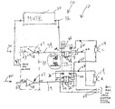
- FIGURE shows a block diagram and switch/loudspeaker arrangement according to aspects of the present invention
- the FIGURE shows a block diagram and switch/loudspeaker arrangement of an acoustic signal reproducing apparatus according to aspects of the present invention.
- the acoustic signal reproducing system of the present invention includes a television receiver 10 and an audio signal reproducing apparatus 12 including loudspeakers 14 .
- Apparatus 12 has a selector switch 16 , amplifiers 18 , an external input terminal 20 and an amplifier output terminal 27 coupling respective amplifier output signals to respective output leads 22 , 34 .
- the audio signal is supplied to input terminal 23 of respective amplifier 18 and respective output terminals 27 are connected to respective fixed terminals 24 of selector switch 16 .
- Leads 22 coupled to respective loudspeakers 14 connect to fixed terminals 25 of switch 16 .
- a signal at external input terminal 20 is connected to fixed terminal(s) 26 of selector switch 16 .
- Movable contact 28 is movable to position “A” for selection to internally drive respective loudspeakers 14 from amplifiers 18 through output signal leads 22 , 34 . Loudspeakers 14 are driven from the signal available at the external input terminal 20 when movable contact 28 is moved to position “B”.
- the external audio signal reproducing apparatus connectable to terminal 20 is a surround sound system having a center loudspeaker terminal for connection to a loudspeaker to receive a center L+R signal.
- This center loudspeaker would be disposed between the left and right front stereophonic loudspeakers, e.g., the loudspeaker units of a surround sound system typically are each arranged at a front right position (FR), a front left position (FL), a front center position (FC), a surround right position (SR) and a surround left position (SL) respectively, in a manner known in the art.
- loudspeaker(s) 14 can be used in place of any of the loudspeakers of the surround sound system or any other loudspeaker of any other type of sound system depending upon the signal provided at terminal 20 .
- the television receiver since the television receiver has stereo auxiliary audio input terminals 40 , the television receiver can provide a stereo expansion effect (not shown) for a stereo signal coupled to such auxiliary input terminals 40 with the movable contact 28 switched in direction “A”.
- loudspeakers 14 connectable to external input terminal 20 of the television receiver 10 in switch position “B”, provides that the speaker system 14 can be commonly used by both the television receiver 10 and the external program source.
- the speaker system 14 has at least one loudspeaker unit, and in the exemplary embodiment has two loudspeakers because television receiver 10 is a stereophonic sound receiver. If the audio signal is provided by a surround sound audio system, the speaker system 14 can then serve as the front center loudspeaker (FC) as discussed above.
- the loudspeakers 14 When the two or more loudspeakers 14 are disconnected from their respective amplifier 18 and are connected by switch 16 to terminal 20 , the loudspeakers are connected in series with each other, i.e., their impedances are additive.
- the power output is reduced by one half due to the doubling of the load impedance.
- This has the benefit of permitting the loudspeakers to be powered by an external power amplifier which is rated to be higher in power output than each of power amplifiers 18 , so that the loudspeakers will have an improved ability to not be damaged by such exposure to higher power.
- This has the further benefit that the power rating of the loudspeakers need only to be matched to the power output of their respective amplifier 18 , thus permitting the use of less expensive loudspeakers.
- the present amplifiers 18 are alike since they are in the same IC, the amplifiers 18 can have differing output power and be greater in number than just two. Further, even though the present embodiment shows a single input terminal 20 , a plurality of input terminals can be used for a plurality of external amplifiers, which need not have identical output power. Obviously, in such cases, switch 16 will change accordingly.
- Switch 16 When switch 16 is in the “center” position, i.e., switched in direction “B”, loudspeakers 14 are no longer loading respective amplifiers 18 . Accordingly, upon the switching to the “center” position of switch 16 , a muting circuit 30 is actuated by switch 16 . Muting circuit 30 is actuated in response to the connection of amplifier 18 output line 34 to the muting circuit 30 input line 36 at switch terminal 38 . Muting circuit 30 applies a voltage and/or components coupled to ground (not shown), to a muting pin 32 of integrated circuit 33 , to mute the integrated circuit or to place it in a standby mode, in a manner known in the art.
- Amplifiers 18 are part of a TDA7490 integrated circuit made by STMicroelectronics headquartered in Geneva, Switzerland, and are 25 watt stereo Class D amplifiers.
- the power supply, oscillator, and high frequency output filters are not shown in the FIGURE and form no part of the present invention.
- Switch 16 is a break-before-make slide switch but any other suitable switch can be used, e.g., a toggle switch, a relay.
Abstract
There is provided an acoustic sound reproducing apparatus for a first audio signal and having an input terminal for receiving a second audio signal, a selector switch and at least one loudspeaker. The at least one loudspeaker is driven by an output signal from one of the first or second audio signal through the selector switch. As a result, the acoustic sound reproducing apparatus, and the apparatus providing the second audio signal, can commonly use a single loudspeaker or set of loudspeakers. When the external audio signal is selected, the internal loudspeaker(s) becomes part of the external loudspeaker arrangement for a surround sound system. When more than one loudspeaker is used, the loudspeakers are connected to each other in series when they are connected to be driven by the external second audio input signal instead of each being driven by their respective amplifiers. This permits the loudspeakers to be driven by an external amplifier having a higher power output than the internal power amplifier so that the loudspeakers will not be damaged when driven by a higher power external amplifier.
Description
- The present invention relates generally to acoustic sound reproducing apparatus, and more particularly, to a loudspeaker arrangement and switching apparatus therefor.
- A television receiver with its loudspeakers, and an audio sound system with its loudspeakers, are often disposed in a common listening room with the two not generally operated at the same time because the user cannot simultaneously listen to both when each has its own program source. Thus, the utilization efficiency of each of the various loudspeakers is reduced. For example, if the audio signal is a stereophonic signal reproduced in a multidirectional surround sound system such as a Dolby™ 5.1 sound system, five loudspeakers are used with one of the loudspeakers being a center loudspeaker which receives an L+R signal. The television receiver, e.g., if it uses an MTS stereo system, has at least two loudspeakers. Thus, because both systems cannot be simultaneously listened to when each has its own program source, the space efficiency of the listening room is also reduced.
- One such attempt to improve the utilization efficiency of the various loudspeakers and to improve the space efficiency of the listening room is shown in U.S. Pat. No. 5,329,371.
- There is provided an acoustic sound reproducing apparatus for a first audio signal and having an input terminal for a second audio signal, a selector switch and at least one loudspeaker. The at least one loudspeaker is driven by an output signal from one of the first or second audio signal through the selector switch. As a result, the acoustic sound reproducing apparatus, which in the exemplary embodiment is a television receiver, and the apparatus providing the second audio signal, which in the exemplary embodiment is a surround sound audio system, can commonly use a single loudspeaker or plurality of loudspeakers. When the external audio signal is selected, the at least one internal loudspeaker becomes part of the external loudspeaker arrangement for the surround sound system.
- When more than one loudspeaker is used, the loudspeakers are connected to their respective amplifiers and are connected to each other in series when they are connected by the selector switch to be driven by the external second audio signal. This permits the loudspeakers to be driven by an external amplifier having a higher power output than the internal power amplifier, so that the loudspeakers will not be damaged when driven by such a higher power external amplifier. U.S. Pat. No. 4,146,745 shows loudspeakers connected in series.
- The FIGURE shows a block diagram and switch/loudspeaker arrangement according to aspects of the present invention
- The FIGURE shows a block diagram and switch/loudspeaker arrangement of an acoustic signal reproducing apparatus according to aspects of the present invention. The acoustic signal reproducing system of the present invention includes a
television receiver 10 and an audiosignal reproducing apparatus 12 includingloudspeakers 14. -
Apparatus 12 has a selector switch 16,amplifiers 18, anexternal input terminal 20 and anamplifier output terminal 27 coupling respective amplifier output signals to respective output leads 22, 34. The audio signal is supplied toinput terminal 23 ofrespective amplifier 18 andrespective output terminals 27 are connected to respectivefixed terminals 24 of selector switch 16.Leads 22 coupled torespective loudspeakers 14, connect tofixed terminals 25 of switch 16. A signal atexternal input terminal 20 is connected to fixed terminal(s) 26 of selector switch 16. Movable contact 28 is movable to position “A” for selection to internally driverespective loudspeakers 14 fromamplifiers 18 through output signal leads 22, 34.Loudspeakers 14 are driven from the signal available at theexternal input terminal 20 when movable contact 28 is moved to position “B”. - In the exemplary embodiment, the external audio signal reproducing apparatus connectable to
terminal 20, is a surround sound system having a center loudspeaker terminal for connection to a loudspeaker to receive a center L+R signal. This center loudspeaker would be disposed between the left and right front stereophonic loudspeakers, e.g., the loudspeaker units of a surround sound system typically are each arranged at a front right position (FR), a front left position (FL), a front center position (FC), a surround right position (SR) and a surround left position (SL) respectively, in a manner known in the art. However, it is within the contemplation of the present invention that loudspeaker(s) 14 can be used in place of any of the loudspeakers of the surround sound system or any other loudspeaker of any other type of sound system depending upon the signal provided atterminal 20. Additionally, since the television receiver has stereo auxiliaryaudio input terminals 40, the television receiver can provide a stereo expansion effect (not shown) for a stereo signal coupled to suchauxiliary input terminals 40 with the movable contact 28 switched in direction “A”. - Thus,
loudspeakers 14 connectable toexternal input terminal 20 of thetelevision receiver 10 in switch position “B”, provides that thespeaker system 14 can be commonly used by both thetelevision receiver 10 and the external program source. Thespeaker system 14 has at least one loudspeaker unit, and in the exemplary embodiment has two loudspeakers becausetelevision receiver 10 is a stereophonic sound receiver. If the audio signal is provided by a surround sound audio system, thespeaker system 14 can then serve as the front center loudspeaker (FC) as discussed above. - When the two or
more loudspeakers 14 are disconnected from theirrespective amplifier 18 and are connected by switch 16 toterminal 20, the loudspeakers are connected in series with each other, i.e., their impedances are additive. Thus, for an external power amplifier having a transformerless output, which is the case for almost all contemporary audio power amplifiers, the power output is reduced by one half due to the doubling of the load impedance. This has the benefit of permitting the loudspeakers to be powered by an external power amplifier which is rated to be higher in power output than each ofpower amplifiers 18, so that the loudspeakers will have an improved ability to not be damaged by such exposure to higher power. This has the further benefit that the power rating of the loudspeakers need only to be matched to the power output of theirrespective amplifier 18, thus permitting the use of less expensive loudspeakers. - It is within the contemplation of the present invention that even though the
present amplifiers 18 are alike since they are in the same IC, theamplifiers 18 can have differing output power and be greater in number than just two. Further, even though the present embodiment shows asingle input terminal 20, a plurality of input terminals can be used for a plurality of external amplifiers, which need not have identical output power. Obviously, in such cases, switch 16 will change accordingly. - When switch 16 is in the “center” position, i.e., switched in direction “B”,
loudspeakers 14 are no longer loadingrespective amplifiers 18. Accordingly, upon the switching to the “center” position of switch 16, amuting circuit 30 is actuated by switch 16.Muting circuit 30 is actuated in response to the connection ofamplifier 18output line 34 to themuting circuit 30input line 36 atswitch terminal 38.Muting circuit 30 applies a voltage and/or components coupled to ground (not shown), to a muting pin 32 of integratedcircuit 33, to mute the integrated circuit or to place it in a standby mode, in a manner known in the art. -
Amplifiers 18 are part of a TDA7490 integrated circuit made by STMicroelectronics headquartered in Geneva, Switzerland, and are 25 watt stereo Class D amplifiers. The power supply, oscillator, and high frequency output filters are not shown in the FIGURE and form no part of the present invention. - Switch 16 is a break-before-make slide switch but any other suitable switch can be used, e.g., a toggle switch, a relay.
Claims (10)
1. A television receiver comprising:
audio amplification means for providing an output audio signal to a loudspeaker;
loudspeaker means disposed within a cabinet of the television receiver for switchably receiving said audio signal and producing a corresponding audio sound;
audio input means for receiving an audio signal from an external multidirectional sound system, and
switch means for switchably connecting the loudspeaker means between the output of the audio amplification means and the audio input means so that the loudspeaker means can operationally function as part of the multidirectional sound system.
2. The television receiver of claim 1 wherein the audio signal from the multidirectional sound system comprises a center loudspeaker signal.
3. The receiver of claim 1 wherein the amplification means includes stereo amplifiers for respectively driving a plurality of loudspeakers, the loudspeakers are connected in series with each other when they are coupled by the switching means to the audio input means.
4. An acoustic sound reproducing system comprising:
a television receiver having audio amplification means and connectable to a surround sound system;
audio input means for the television receiver to receive an audio power signal from a surround sound system;
a loudspeaker mounted within a cabinet of the television receiver and drivable from the audio amplification means and from the surround sound system, and
switch means for switchably connecting the loudspeaker between the audio amplification means and the connection to the surround sound system.
5. A television receiver comprising:
audio amplification means including stereo amplifiers for respectively driving a plurality of loudspeakers with respective audio power signals;
loudspeaker means including a plurality of loudspeakers disposed within a cabinet of the television receiver for switchably receiving said respective audio power signals and producing a corresponding audio sound;
audio input means for receiving an audio power signal from an external source, and
switch means for switchably connecting the loudspeaker means between the audio amplification means and the audio input means, the loudspeakers being connected in series with each other when they are coupled to the audio input means.
6. The television receiver of claim 5 wherein the audio amplification means is disabled when the switch means connects the loudspeakers to the audio input means.
7. The television receiver of claim 6 wherein the disabling of the audio amplification means comprises a standby mode.
8. The television receiver of claim 6 wherein the disabling of the audio amplification means comprises a muting means.
9. A television receiver comprising:
amplifier means for amplifying at least two first audio signals and having an output of said signals;
at least two loudspeakers disposed in a cabinet of said amplifier means;
an input terminal for receiving a second audio signal from an external surround sound system;
selector means for choosing one of the output audio signal from said amplifier means and the second audio signal through said input terminal, and applying the selected signal to the at least two loudspeakers so that the at least two loudspeakers can operationally be part of the surround sound system with the at least two loudspeakers being connected in series with each other.
10. An acoustic sound reproducing system comprising:
a television receiver including an audio signal reproducing apparatus;
selector means for exchanging between an output signal from said audio signal reproducing apparatus and an externally provideable input signal, and
a loudspeaker disposed within said television receiver, said loudspeaker being driven by a selected audio signal from said selector means,
the external input signal being provideable by a surround sound audio system having other loudspeakers, the loudspeaker working with the other loudspeakers when selected by the selector means.
Priority Applications (6)
| Application Number | Priority Date | Filing Date | Title |
|---|---|---|---|
| US10/126,746 US20030197811A1 (en) | 2002-04-19 | 2002-04-19 | Loudspeaker arrangement and switching apparatus therefor |
| JP2003098568A JP2003319487A (en) | 2002-04-19 | 2003-04-01 | Acoustic sound reproducer |
| EP03290832A EP1355510A3 (en) | 2002-04-19 | 2003-04-03 | Loudspeaker arrangement and switching apparatus therefor |
| KR10-2003-0021285A KR20030083579A (en) | 2002-04-19 | 2003-04-04 | Loudspeaker arrangement and switching apparatus therefor |
| MXPA03003248A MXPA03003248A (en) | 2002-04-19 | 2003-04-11 | Loudspeaker arrangement and switching apparatus therefor. |
| CN03122914A CN1452435A (en) | 2002-04-19 | 2003-04-17 | Loudspeaker apparatus and switch device thereof |
Applications Claiming Priority (1)
| Application Number | Priority Date | Filing Date | Title |
|---|---|---|---|
| US10/126,746 US20030197811A1 (en) | 2002-04-19 | 2002-04-19 | Loudspeaker arrangement and switching apparatus therefor |
Publications (1)
| Publication Number | Publication Date |
|---|---|
| US20030197811A1 true US20030197811A1 (en) | 2003-10-23 |
Family
ID=29215094
Family Applications (1)
| Application Number | Title | Priority Date | Filing Date |
|---|---|---|---|
| US10/126,746 Abandoned US20030197811A1 (en) | 2002-04-19 | 2002-04-19 | Loudspeaker arrangement and switching apparatus therefor |
Country Status (1)
| Country | Link |
|---|---|
| US (1) | US20030197811A1 (en) |
Cited By (1)
| Publication number | Priority date | Publication date | Assignee | Title |
|---|---|---|---|---|
| US20080316367A1 (en) * | 2004-01-23 | 2008-12-25 | Thomson Licensing S.A. | Selectable Audio Output Configuration |
Citations (11)
| Publication number | Priority date | Publication date | Assignee | Title |
|---|---|---|---|---|
| US4139866A (en) * | 1976-02-18 | 1979-02-13 | Telesonics, Inc. | Stereophonic television sound transmission system |
| US4410761A (en) * | 1980-11-05 | 1983-10-18 | Willi Schickedanz | Stereo loudspeaker system for a picture reproducing screen |
| US4479235A (en) * | 1981-05-08 | 1984-10-23 | Rca Corporation | Switching arrangement for a stereophonic sound synthesizer |
| US4496979A (en) * | 1983-11-22 | 1985-01-29 | Casat Technology, Inc. | FM High-fidelity processor |
| US4525820A (en) * | 1980-03-19 | 1985-06-25 | Hitachi, Ltd. | Function selecting method and system for an audio/video recording and reproducing system |
| US4750206A (en) * | 1986-10-28 | 1988-06-07 | Recoton Corporation | Adapter for TV stereo, SAP and auxiliary signals |
| US5237418A (en) * | 1990-09-04 | 1993-08-17 | Sony Corporation | Audio output circuit in electronic apparatus with composite display function |
| US5329371A (en) * | 1991-12-13 | 1994-07-12 | Sony Corporation | Loudspeaker system automatically switched between video and audio units |
| US5426510A (en) * | 1992-06-05 | 1995-06-20 | Dolman Associates, Inc. | Audio-video system |
| US6034737A (en) * | 1996-09-02 | 2000-03-07 | Sony Corporation | TV set and a combination apparatus of a TV set and an AV amplifier |
| US6151077A (en) * | 1994-12-22 | 2000-11-21 | U.S. Philips Corporation | Interface system for a television receiver |
-
2002
- 2002-04-19 US US10/126,746 patent/US20030197811A1/en not_active Abandoned
Patent Citations (11)
| Publication number | Priority date | Publication date | Assignee | Title |
|---|---|---|---|---|
| US4139866A (en) * | 1976-02-18 | 1979-02-13 | Telesonics, Inc. | Stereophonic television sound transmission system |
| US4525820A (en) * | 1980-03-19 | 1985-06-25 | Hitachi, Ltd. | Function selecting method and system for an audio/video recording and reproducing system |
| US4410761A (en) * | 1980-11-05 | 1983-10-18 | Willi Schickedanz | Stereo loudspeaker system for a picture reproducing screen |
| US4479235A (en) * | 1981-05-08 | 1984-10-23 | Rca Corporation | Switching arrangement for a stereophonic sound synthesizer |
| US4496979A (en) * | 1983-11-22 | 1985-01-29 | Casat Technology, Inc. | FM High-fidelity processor |
| US4750206A (en) * | 1986-10-28 | 1988-06-07 | Recoton Corporation | Adapter for TV stereo, SAP and auxiliary signals |
| US5237418A (en) * | 1990-09-04 | 1993-08-17 | Sony Corporation | Audio output circuit in electronic apparatus with composite display function |
| US5329371A (en) * | 1991-12-13 | 1994-07-12 | Sony Corporation | Loudspeaker system automatically switched between video and audio units |
| US5426510A (en) * | 1992-06-05 | 1995-06-20 | Dolman Associates, Inc. | Audio-video system |
| US6151077A (en) * | 1994-12-22 | 2000-11-21 | U.S. Philips Corporation | Interface system for a television receiver |
| US6034737A (en) * | 1996-09-02 | 2000-03-07 | Sony Corporation | TV set and a combination apparatus of a TV set and an AV amplifier |
Cited By (2)
| Publication number | Priority date | Publication date | Assignee | Title |
|---|---|---|---|---|
| US20080316367A1 (en) * | 2004-01-23 | 2008-12-25 | Thomson Licensing S.A. | Selectable Audio Output Configuration |
| US8243208B2 (en) | 2004-01-23 | 2012-08-14 | Thomson Licensing | Selectable audio output configuration |
Similar Documents
| Publication | Publication Date | Title |
|---|---|---|
| US6813528B1 (en) | Apparatus and method for outputting audio signal of laptop computer coupled with docking station | |
| US5581626A (en) | Automatically switched equalization circuit | |
| US4491694A (en) | Telephone to stereo amplifier interface coupling | |
| US20090016539A1 (en) | A/v amplifier and method for driving the same | |
| US3944941A (en) | Switching circuit for use with balanced transformerless amplifier | |
| US6529787B2 (en) | Multimedia computer speaker system with bridge-coupled subwoofer | |
| US8014531B2 (en) | Stereo/monaural switching circuit and integrated circuit having the same | |
| EP1355510A2 (en) | Loudspeaker arrangement and switching apparatus therefor | |
| US20030197811A1 (en) | Loudspeaker arrangement and switching apparatus therefor | |
| US20030198358A1 (en) | Loudspeaker arrangement and switching apparatus therefor | |
| US4631490A (en) | Audio output amplifying device | |
| US5123051A (en) | Sound field reproducing apparatus | |
| JPH02260900A (en) | Voice signal input changeover device in electronic device | |
| KR0138977Y1 (en) | Mono/stereo auto-switching stereo sound output device | |
| CN112565982B (en) | Interactive sound box and sound reinforcement method using same | |
| GB2387979A (en) | A connector interface for a mobile phone | |
| JPH09214265A (en) | Power amplifier circuit | |
| US20100079205A1 (en) | Multi-Channel Amplifier | |
| CA1321756C (en) | Sound field reproducing apparatus | |
| JPH084799Y2 (en) | Stereo switching device | |
| JPH04115799A (en) | Speaker changeover circuit | |
| JPS6115670Y2 (en) | ||
| JPH06225243A (en) | Sound output switching circuit | |
| CN111294703A (en) | Multi-mode effect switching combined karaoke power amplifier | |
| JPH0559606B2 (en) |
Legal Events
| Date | Code | Title | Description |
|---|---|---|---|
| AS | Assignment |
Owner name: THOMSON LICENSING S.A., FRANCE Free format text: ASSIGNMENT OF ASSIGNORS INTEREST;ASSIGNORS:HOOVER, ALAN ANDERSON;MORRIS, ROBERT EDWARD;SIMPSON, MARK ALAN;REEL/FRAME:013107/0819;SIGNING DATES FROM 20020708 TO 20020712 |
|
| STCB | Information on status: application discontinuation |
Free format text: ABANDONED -- FAILURE TO RESPOND TO AN OFFICE ACTION |