US20030197794A1 - Image input apparatus and method - Google Patents
Image input apparatus and method Download PDFInfo
- Publication number
- US20030197794A1 US20030197794A1 US10/413,304 US41330403A US2003197794A1 US 20030197794 A1 US20030197794 A1 US 20030197794A1 US 41330403 A US41330403 A US 41330403A US 2003197794 A1 US2003197794 A1 US 2003197794A1
- Authority
- US
- United States
- Prior art keywords
- image
- compression
- input apparatus
- signal
- processing
- Prior art date
- Legal status (The legal status is an assumption and is not a legal conclusion. Google has not performed a legal analysis and makes no representation as to the accuracy of the status listed.)
- Granted
Links
Images


Classifications
-
- H—ELECTRICITY
- H04—ELECTRIC COMMUNICATION TECHNIQUE
- H04N—PICTORIAL COMMUNICATION, e.g. TELEVISION
- H04N7/00—Television systems
- H04N7/14—Systems for two-way working
- H04N7/141—Systems for two-way working between two video terminals, e.g. videophone
- H04N7/147—Communication arrangements, e.g. identifying the communication as a video-communication, intermediate storage of the signals
Definitions
- the present invention relates to an image input apparatus of a video conferencing system.
- Video conferencing systems using personal computers are known, such as PCS100 and PCS50 from Picture Tel Corporation and Proshare from Intel Corporation.
- Such personal computer based video conferencing systems are also called a Desk Top Video Conferencing System (DTVC).
- DTVC Desk Top Video Conferencing System
- FIG. 5 is a block diagram of DTVC designed by present inventors.
- reference numeral 101 represents a video camera
- reference numeral 102 represents a video board having an image pickup function and a data compression function
- reference numeral 103 represents a communication board interfacing with, for example, an ISDN line
- reference numeral 104 represents a floppy disk for storing video conferencing software.
- the video board 102 and the communication board 103 are expansion boards for personal computers and are inserted into expansion slots of the personal computers.
- FIG. 6 is a perspective view of a personal computer with the video board 102 and the communication board 103 being inserted into expansion slots and with the video camera 101 being mounted on a monitor 108 of the personal computer.
- Reference numeral 105 represents the main body of the personal computer
- reference numeral 106 represents a mouse
- reference numeral 107 represents a keyboard.
- the floppy disk 104 with video conferencing software is inserted into a disk drive of the personal computer 105 and an operator enters necessary commands to load the video conferencing software into a hard disk (not shown) of the personal computer.
- the video conferencing software After the video conferencing software is loaded, it is activated by entering necessary commands. Then, an image (LOCAL) of an operator is picked up with the video camera 101 and displayed on the screen of the monitor 108 .
- FIG. 7 illustrates an image of the operator displayed on the monitor 108 .
- a remote side is called, for example, via an ISDN line by entering necessary commands.
- an image (REMOTE) of the partner is displayed on the monitor 108 .
- FIG. 8 illustrates the images of the operator (LOCAL) and the partner (REMOTE) displayed on the monitor 108 . In the above manner, video conferencing is made between the two participants.
- a still image is taken in a moving image mode.
- the video camera 101 shown in FIG. 6 is dismounted from the monitor 108 and mounted on a document pickup stand to take an image of a document.
- an image is transmitted in accordance with the ITU-T International Standards, for example, a protocol stipulated by H320.
- a moving image containing video and audio signals is transmitted at a transmission rate of 64 Kbps (56 Kbps in USA) of a general ISDN line.
- a moving image is compressed greatly at about ⁇ fraction (1/100) ⁇ to ⁇ fraction (1/200) ⁇ by using interframe correlation for moving image compensation stipulated by H261.
- a still image picked up by this compression scheme gradually increases its resolution in several seconds to ten and several seconds.
- a still image is picked up in a still image mode.
- the video camera 101 shown in FIG. 6 is dismounted from the monitor 108 and mounted, for example, on a document pickup stand.
- a still image pickup mode of software is selected, for example, by clicking a mouse to freeze a still image.
- an image input apparatus which comprises image pickup means and processing means for compressing a video signal transmitted from the image pickup means, the image pickup means including switching means for switching an image pickup between a moving image and a still image and notification means for notifying the processing means of an on/off state of the switching means, and the processing means including first compression means for executing compression suitable for the moving image, second compression means for executing compression suitable for the still image, and selection means for selecting the first or second compression means in accordance with the notified on/off state.
- FIG. 1 is a block diagram showing the structure of an image input apparatus according to a first embodiment.
- FIG. 2 is a diagram illustrating a window for a still image displayed on a monitor.
- FIG. 3 is a diagram illustrating windows for still images sequentially picked up.
- FIG. 4 is a block diagram showing the structure of an image input apparatus according to a second embodiment.
- FIG. 5 is a block diagram showing the structure of a conventional DTVC.
- FIG. 6 is a perspective view of a personal computer with a video board and a communication board being inserted and a video camera being mounted on a monitor of the personal computer.
- FIG. 7 is a diagram illustrating the image of an operator displayed on the monitor.
- FIG. 8 is a diagram illustrating the images of the operator and a partner at a remote site displayed on the monitor.
- FIG. 9 is a flow chart illustrating the operation of a shutter interrupt process routine by a video camera microcomputer.
- FIG. 10 is a flow chart illustrating the operation of a shutter interrupt process routine by an expansion board (external adapter) microcomputer.
- FIG. 11 is comprised of FIGS. 11A and 11B showing a flow chart illustrating the operation of a shutter interrupt process routine on a personal computer side.
- Embodiments of an image input apparatus of the invention will be described.
- the image input apparatus of each embodiment is applied to video conferencing systems.
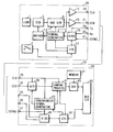
- FIG. 1 is a block diagram showing the image input apparatus according to the first embodiment of the invention.
- the image input apparatus has a video camera 28 and an expansion board 55 mounted on a personal computer (not shown).
- reference numeral 1 represents a lens
- reference numeral 2 represents a shutter release switch
- reference numeral 3 represents an image pickup element (CCD).
- Reference numeral 5 represents an automatic gain controller (AGC) circuit and a sample/hold circuit which are generally formed on a single IC.
- Reference numeral 7 represents a CCD driver
- reference numeral 9 represents a timing generator for supplying timing signals to AGC 5 , CCD 3 , 75 ⁇ driver 11 to be described later, and the like
- reference numeral 11 represents the 75 ⁇ driver for a sampling clock
- reference numeral 13 represents a 75 ⁇ drive for a sampled/held CCD output.
- Reference numeral 15 represents a Vertical Interval Data Signal (VIDS) circuit for embedding data during a vertical blanking period
- reference numeral 17 represents a microcomputer (CPU)
- reference numeral 19 represents a sampling clock output terminal
- reference numeral 21 represents a CCD output terminal for a sampled/held CCD output
- reference numeral 23 represents an output terminal for a VIDS signal from the video camera.
- VIDS Vertical Interval Data Signal
- Reference numeral 25 represents a VIDS signal input terminal for the video camera 28
- reference numeral 27 represents a composite synchronous signal input terminal.
- Reference numeral 29 represents a sampling clock input terminal mounted on the expansion board 55 of the personal computer.
- Reference numeral 31 represents an input terminal for the CCD signal
- reference numeral 33 represents an input terminal for the VIDS signal from the video camera 28
- reference numeral 35 represents an output terminal for the VIDS signal to be supplied to the video camera 28
- reference numeral 37 represents a composite synchronous signal output terminal
- reference numeral 39 represents an A/D converter
- reference numeral 41 represents a digital camera process circuit
- reference numeral 43 represents a synchronous signal generator (SSG)
- reference numeral 45 represents a digital signal processor (DSP) for data compression.
- SSG synchronous signal generator
- DSP digital signal processor
- Reference numeral 47 represents a memory for DSP 45 which is constituted of a ROM part for storing DSP programs and a RAM part for processing data of DSP 45 .
- Reference numeral 49 represents a VIDS circuit for inserting data during the vertical blanking period of a video signal
- reference numeral 51 represents a microcomputer (CPU)
- reference numeral 53 represents a bus I/F circuit for transfer data to and from the personal computer. These constituent elements 29 to 53 are fabricated on the expansion board.
- Reference numeral 57 represents a camera cable interconnecting the video camera 28 and the expansion board 55 .
- CPU of the personal computer Upon activation, CPU of the personal computer initializes DSP 45 via the bus I/F circuit 53 and thereafter sets DSP 45 to a moving image compression H261 mode which is a first compression mode. This setting may be performed by loading a moving image compression program stored in the memory 47 into DSP 45 or by transmitting the moving image compression program from the personal computer via the bus I/F 53 .
- CPU of the personal computer initializes CPU 51 of the expansion board 55 via the bus I/F circuit 53 . Upon this initialization, CPU 51 establishes a bi-directional communication channel to CPU 17 of the video camera 28 via the VIDS circuits 15 and 49 .
- CPU 51 sets the contents of the digital camera process circuit 41 and the synchronous signal generator (SSG) 43 .
- the contents of this setting include setting NTSC or PAL, setting 270 thousands pixels or 410 thousands pixels of CCD pixels, and other settings.
- Similar setting data is transferred from CPU 51 of the expansion board 55 to CPU 17 of the video camera via the communication channel.
- CPU 17 of the video camera 28 therefore sets the contents of the timing generator 9 and the AGC sample/hold circuit 5 .
- the CCD driver 7 converts a predetermined timing pulse supplied from the timing generator 9 into a CCD drive waveform and supplies it to CCD 3 .
- An image focussed on CCD 3 via the lens 1 is therefore input to the AGC sample/hold circuit 5 .
- the digital camera process circuit 41 of the expansion board 55 forms a control loop with these circuit elements to realize AE (automatic exposure or automatic iris). This is not relevant to this invention, and so the detailed description thereof is omitted.
- An output signal from the AGC sample/hold circuit 5 is supplied to the 75 ⁇ driver 13 and sent via the output terminal 21 and cable 57 to the input terminal 31 of the expansion board 55 .
- a CCD sampling clock generated by the timing generator 9 is supplied to the 75 ⁇ driver 11 and sent via the output terminal 19 and cable 57 to the input terminal 29 of the expansion board 55 .
- the sampling clock is supplied to the A/D converter 39 which converts the CCD signal into a digital signal.
- the sampling clock is also supplied as a master clock signal to the synchronous signal generator (SSG) 43 and digital camera process circuit 41 .
- SSG 43 generates a predetermined composite synchronous signal and supplies it to the VIDS circuit 49 of the expansion board 55 and to the VIDS circuit 15 of the video camera 28 via the output terminal 37 , cable 57 , and input terminal 27 , to thereby synchronize both the VIDS circuits 15 and 49 .
- An output signal from the A/D converter 39 is sent to the video camera process circuit 41 which performs various color processing and eventually outputs digital Y and U/V signals to DSP 45 .
- DSP 45 already set to the moving image compression mode compresses the moving image data of Y and U/V signals by using the memory 47 for calculation.
- the compressed results are transferred via the bus I/F circuit 53 to the personal computer to display the local image on the monitor in the manner illustrated in FIG. 7.
- a method of transferring the image to the remote side and a method of receiving and displaying the image at the remote side are not relevant to this invention, and so the description thereof is omitted.
- the user depresses the shutter release switch 2 .
- This depression is detected by CPU 17 of the video camera 28 and is notified to CPU 51 of the expansion board 55 , via the VIDS circuit 15 of the video camera 28 and the VIDS circuit 49 of the expansion board 55 .
- This notification information is supplied via the bus I/F circuit 53 to the video conferencing software running on the personal computer. Upon reception of this information, the video conferencing software changes at a predetermined timing via the bus I/F circuit 53 the setting of DSP 45 to the still image compression mode which is a second compression mode.
- the Y and U/V signals input to DSP 45 are processed as a still image of one frame at a predetermined timing or as a still image of one field through software setting, to execute still image data compression.
- the execution results are supplied via the bus I/F circuit 53 to the video conferencing software running on the personal computer to display a still image in a window of the monitor.
- FIG. 2 illustrates a still image in a window displayed on the monitor.
- DSP 45 resumes the moving image compression mode to update the local moving image window.
- DSP 45 is controlled to maintain the still image mode while the shutter release switch 2 is depressed, to thereby generate a plurality of still image windows in the order of pickup.
- FIG. 3 illustrates a plurality of windows with still images being displayed therein in the order of pickup.
- DSP 45 is controlled to resume the moving image compression mode to update the local moving image window.
- a still image is generally an image of a document, drawing, name card, or the like. In this case, it is preferable that blue is somewhat emphasized to make a paper sheet whitish.
- a moving image is generally an image of a person. In this case, it is preferable that red is somewhat emphasized to make the color of a face look better.
- the set value of white balance may be shifted by a predetermined amount to the blue color while the shutter release switch 2 is depressed, and while the shutter release switch 2 is detached, the original set value for a person (toward red) may be resumed.
- OCR optical character recognition
- the operation of changing the set value of white balance can be performed, for example, by controlling the digital camera process circuit 41 when CPU 51 of the expansion board 55 shown in FIG. 1 detects a depression of the shutter release switch 2 .
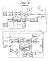
- FIG. 4 is a block diagram showing the structure of the image input apparatus of the second embodiment.
- reference numeral 12 represents an adder
- reference numeral 18 represents a separation circuit
- reference numeral 22 represents an output terminal for an addition signal of a CCD signal and a VIDS signal
- reference numeral 26 represents an input terminal for an addition signal of a composite synchronous signal and a VIDS signal.
- Reference numeral 32 represents an input terminal on the expansion board 55 for an addition signal of the CCD signal and the VIDS signal
- reference numeral 36 represents an output terminal on the expansion board 55 for an addition signal of the composite synchronous signal and the VIDS signal
- reference numeral 38 represents a separation circuit
- reference numeral 50 represents an adder
- reference numeral 52 represents a 75 ⁇ driver.
- a pair of the CCD signal and VIDS signal and a pair of the composite synchronous signal and VIDS signal are each multiplexed to reduce the number of wires of the connection cable 57 .
- the other structures are the same as the first embodiment.
- the CCD signal and VIDS signal may be multiplexed, and the composite synchronous signal and VIDS signal may be separated similar to the first embodiment, or conversely the CCD signal and VIDS signal may be separated similar to the first embodiment, and the composite synchronous signal and VIDS signal may be multiplexed.
- the expansion board 55 for processing video signals mounted in the personal computer in the first and second embodiments can be replaced by an external adapter mounted externally of the personal computer.
- This external adapter I/F may be high speed serial I/F (IEEE 1394), low speed serial I/F such as USB, RS232C, or parallel I/F such as SCSI and bi-directional Centronics.
- CCD signals pass through the connection cable 57 .
- NTSC signals may be passed through the connection cable 57 with the same advantageous effects of this invention, by mounting an A/D converter, a digital camera process circuit, an NTSC encoder, and the like on the video camera 28 and by mounting an NTSC decoder on the expansion board 55 .
- FIGS. 9, 10, 11 A and 11 B are flow charts illustrating the operations of processes to be executed by software of the video camera microcomputer 17 , by software of the expansion board (external adapter) microcomputer, and by software on the personal computer side.
- FIG. 9 is a flow chart illustrating the operation of processes to be executed by the microcomputer 17 of the video camera shown in FIGS. 1 and 4, particularly an interrupt process routine activated by the shutter release switch 2 shown in FIGS. 1 and 4.
- the video camera microcomputer After the power is turned on and a predetermined initializing process is completed, the video camera microcomputer as predetermined operations. Thereafter, the operation periodically jumps to an interrupt process routine, for example, at an interrupt timing of a period of a V synchronous signal supplied from the timing generator 9 in FIGS. 1 and 4.
- Step S 2 in FIG. 9 the microcomputer 17 checks at Step S 2 in FIG. 9 whether the shutter release switch has been depressed. If not, the routine advances to Step S 7 to check a shutter ON flag. Since this flag is not set at the initial stage, this routine is terminated to return to the main routine.
- Step S 3 If the shutter release switch has been depressed at Step S 2 , the routine advances to Step S 3 to check the shutter ON flag. Since this flag is not set at the initial stage, the routine advances to Step S 4 whereat shutter ON information is transmitted to the expansion board (or external adapter) 55 by using the VIDS signal. After transmission, an acknowledge (Ack) signal from the expansion board is awaited at Step S 5 . If the Ack signal is not received, the shutter ON information is again transmitted at Step S 4 . If the Ack signal is received, the shutter ON flag is set at Step S 6 . After the shutter ON flag is set, the interrupt process routine is terminated to return to the main routine.
- Ack acknowledge
- Step S 2 the routine is checked at Step S 2 whether the shutter release switch was depressed. If not, the routine advances to Step S 7 to check the ON flag. Since the ON flag was set, the routine advances to Step S 8 whereat shutter OFF information is transmitted to the expansion board (or external adapter) 55 by using the VIDS signal. After this transmission, an Ack signal from the expansion board is awaited at Step S 9 . If the Ack signal is not received, the shutter OFF information is again transmitted at Step S 8 .
- Step S 10 the shutter ON flag is cleared at Step S 10 .
- the interrupt process routine is terminated to return to the main routine. If it is judged at Step S 2 that the shutter was depressed, it is judged at Step S 3 that the ON flag was set so that the routine returns to the main routine.
- the shutter release switch is released, the shutter OFF information is transmitted to the expansion board (or external adapter)”. With the above routine, the video camera microcomputer can transmit the shutter ON and OFF information.
- FIG. 10 is a flow chart illustrating the operation of processes to be executed by the microcomputer 51 of the expansion board (or external adapter) shown in FIGS. 1 and 4, particularly an interrupt process routine to be activated by the shutter release switch 2 shown in FIGS. 1 and 4.
- the microcomputer as a system controller for the expansion board (or external adapter) starts executing predetermined operations. Thereafter, the microcomputer periodically checks, for example, at an interrupt timing of a period of a V synchronous signal supplied from the synchronous signal generator 43 shown in FIGS. 1 and 4, whether the VIDS circuit 49 has received data. If it is judged that the VIDS circuit has received data transmitted from the video camera, the main routine jumps to Step S 21 of a shutter interrupt process routine shown in FIG. 10.
- the microcomputer 51 checks at Step S 22 whether the received data is the shutter ON information. If it is the shutter ON information, an Ack signal for the shutter ON information is sent back at Step S 23 to the video camera by using the VIDS signal. After the shutter ON information is transmitted at Step S 24 to the personal computer, it is checked at Step S 25 whether an Ack signal is received from the personal computer. If not, the shutter ON information is again transmitted at Step S 24 , whereas if the Ack signal is received, this routine is terminated to return to the main routine.
- Step S 26 If it is judged at Step S 22 that the received data is not the shutter ON information, it is checked at Step S 26 whether the received data is the shutter OFF information. If it is the shutter OFF information, an Ack signal for the shutter OFF information is sent back at Step S 27 to the video camera by using the VIDS signal. Thereafter, the shutter OFF information is transmitted at Step S 28 to the personal computer. It is checked at Step S 29 whether an Ack signal is received from the personal computer. If not, the shutter OFF information is again transmitted at Step S 28 , whereas if the Ack signal is received, this routine is terminated to return to the main routine. If it is judged at Step S 26 that the received data is not the shutter OFF information, this routine is terminated to return to the main routine.
- the microcomputer of the expansion board (or external adapter) transmits the shutter ON and OFF information to the software on the personal computer side.
- FIGS. 11A and 11B are flow charts illustrating the operation of processes to be executed by the personal computer, particularly an interrupt process routine to be activated by the shutter release switch.
- Application software running on the personal computer generally checks an event (external notification information) at a period of 1 millisecond or shorter.
- an event is checked at a period faster than the V period (in NTSC, 16.7 milliseconds).
- DSP 45 shown in FIGS. 1 and 4 is loaded with a moving image compression algorithm, a moving window is displayed on the screen of the personal computer, and an image picked up with the video camera is displayed in this window.
- Techniques such as DMA (Direct Memory Access) are used for displaying a moving image. These techniques are not relevant to this invention, and so the description thereof is omitted.
- Step S 52 As an event is checked at a period of 1 millisecond or shorter at Step S 51 shown in FIG. 11A and if there is an event, the routine advances to Step S 52 to check whether the event is the shutter ON information. If it is the shutter ON information, an Ack signal for the shutter ON information is sent back to the microcomputer of the expansion board (or external adapter). Since the shutter release switch was depressed, the following series of processes for a still image is performed.
- a freeze command is sent at Step S 54 to DSP 45 shown in FIGS. 1 and 4.
- DSP stores video signals of one frame in its memory, synchronously with the period of the V signal.
- DSP stops the DMA transfer of moving images and stores image data of one frame in its memory 47 shown in FIGS. 1 and 4.
- Step S 55 the still image data of one frame in the memory is transferred to the system memory of the personal computer.
- the still image data of one frame in the memory is left undeleted in order to use it for a later compression process.
- the still image data of one frame in the system memory is transferred to a video memory (VRAM) and displayed on another still image window.
- VRAM video memory
- Step S 57 the compression algorithm (e.g., JPEG) is downloaded in DSP which is instructed at Step S 58 to execute compression.
- DSP compresses the still image data of one frame in the memory, and stores the compressed data in the memory.
- compression of the still image data can be executed by the software of the personal computer, it is assumed in this embodiment that DSP executes the compression.
- the compressed data stored in the memory of DSP is transferred at Step S 59 to the system memory of the personal computer. It is checked at Step S 60 whether there is another event. If not, it means continuous depression of the shutter. Therefore, at Step S 61 one frame cycle is delayed and thereafter, the routine returns to Step S 54 to process the next frame.
- Step S 57 may be placed before Step S 54 .
- a time (several seconds) for downloading the algorithm is required before the freeze operation at DSP after the shutter release switch is depressed. This time becomes a time lag.
- Step S 60 If there is another event at Step S 60 , the routine advances to Step S 62 to check whether the event is the shutter OFF information. If not, it means continuous depression of the shutter. Therefore, at Step S 61 one frame cycle is delayed and the routine returns to Step S 54 to process the next frame.
- Step S 62 If it is judged at Step S 62 that the event is the shutter OFF information, it means that the shutter was released. In this case, an Ack signal for the shutter OFF information is sent back at Step S 63 to the microcomputer of the expansion board (or external adapter). Thereafter, at Step S 64 , OCR (optical character recognition) software, for example, is activated.
- OCR optical character recognition
- a still image is often an image of a printed document such as name cards, and after a still image is picked up, OCR software is usually activated to automatically convert character images into character codes. If the OCR software is automatically activated after the release of the shutter, i.e., after the operation of picking up a still image is terminated, the user can easily use the image input apparatus.
- Step S 65 the moving image compression algorithm is again downloaded in DSP. Similar to the operation before depressing the shutter, a moving image is displayed in the moving image window.
- Step S 66 a dialog box is displayed to ask the user whether the still image displayed in the still image window is to be saved in a hard disk as a still image file. If the still image is to be saved, the compressed still image data in the system memory of the personal computer is saved at Step S 67 in the hard disk of the personal computer. If not at Step S 66 , Step S 67 is skipped.
- processing means compresses an image signal transmitted from image pickup means
- switching means provided in the image pickup means switches an image pickup from a moving image to a still image
- notification means notifies the processing means of an on-off state of the switching means
- selection means provided in the processing means selects first compression means suitable for compression of the moving image or second compression means suitable for compression of the still image, in accordance with the notified on-off state.
- the selection means selects said first compression means, and if the switching means is depressed and in an on-state, the selection means changes a selection of the first compression means to a selection of the second compression means and resumes a selection of the first compression means after a lapse of a predetermined time. Accordingly, a still image can be taken only by depressing the switching means and the second compression means can compressed the still image with high quality. It is therefore possible to make the image input apparatus easy to use.
- the predetermined time is a time required for the second compression means at least to compress image signals in unit of frame or field. Accordingly, it is possible to automatically change to the compression suitable for the moving image after the compression of the still image is completed. It is therefor possible to make the image input apparatus easy to use.
- the second compression means certainly can perform compresseion of the video signal on the unit basis of frame or field.
- the second compression means continues to compress image signals in unit of frame or field, and after the lapse of the predetermined time after the switching means is not depressed, an operation by the first compression means resumes. It is therefore possible to sequentially take still images.
- the apparatus further includes display means for displaying the compressed image signals, wherein the display means displays image signals compressed by the first and second compression means in different windows, and the window displaying the image signals compressed by the second compression means is formed separately for each frame or field. Accordingly, a moving image and a still image can be displayed easy to be discriminated. Particularly, still images can be displayed separately for each frame or field.
- the notification means notifies an on/off state of the switching means during a blanking period of the image signals by multiplexing a signal representative of the on/off state with the image signals. It is therefore possible to reduce the number of wires of the cable interconnecting the image pickup means and the processing means.
- the apparatus further includes means for setting a while balance of the image signals to a value shifted for the still image, if the switching means is in an on-state, wherein the second compression means compresses the video signals whose set value is shifted for the still image. Accordingly, it is possible for a user to make a paper sheet of a document, a drawing, or a name card whitish or to make a face color look better, as the user desires it.
- the image pickup means notifies the processing means of an on/off state of switching means for switching an image pickup between a moving image and a still image
- the processing means selects first compression means suitable for compression of the moving image or second compression means suitable for compression of the still image, in accordance with the notified on/off state. Accordingly, when a still image such as a document, a drawing, and a name card becomes necessary to be transmitted to the partner during video conferencing, the still image can be picked up easily by merely operating upon the switching means provided in the image pickup means, and the second compression means can compress the picked-up still image with high quality.
Abstract
Description
- 1. Field of the Invention
- The present invention relates to an image input apparatus of a video conferencing system.
- 2. Related Background Art
- Video conferencing systems using personal computers are known, such as PCS100 and PCS50 from Picture Tel Corporation and Proshare from Intel Corporation. Such personal computer based video conferencing systems are also called a Desk Top Video Conferencing System (DTVC).
- DTVC is now highlighted as a downsized version of a conventional video conferencing system which is configured basing based upon a video monitor and designed for use in a conferencing room. FIG. 5 is a block diagram of DTVC designed by present inventors. In FIG. 5,
reference numeral 101 represents a video camera,reference numeral 102 represents a video board having an image pickup function and a data compression function,reference numeral 103 represents a communication board interfacing with, for example, an ISDN line, andreference numeral 104 represents a floppy disk for storing video conferencing software. - The
video board 102 and thecommunication board 103 are expansion boards for personal computers and are inserted into expansion slots of the personal computers. FIG. 6 is a perspective view of a personal computer with thevideo board 102 and thecommunication board 103 being inserted into expansion slots and with thevideo camera 101 being mounted on amonitor 108 of the personal computer.Reference numeral 105 represents the main body of the personal computer,reference numeral 106 represents a mouse, andreference numeral 107 represents a keyboard. - The
floppy disk 104 with video conferencing software is inserted into a disk drive of thepersonal computer 105 and an operator enters necessary commands to load the video conferencing software into a hard disk (not shown) of the personal computer. - After the video conferencing software is loaded, it is activated by entering necessary commands. Then, an image (LOCAL) of an operator is picked up with the
video camera 101 and displayed on the screen of themonitor 108. FIG. 7 illustrates an image of the operator displayed on themonitor 108. - A remote side is called, for example, via an ISDN line by entering necessary commands. After preset connection operations, an image (REMOTE) of the partner is displayed on the
monitor 108. FIG. 8 illustrates the images of the operator (LOCAL) and the partner (REMOTE) displayed on themonitor 108. In the above manner, video conferencing is made between the two participants. - How voices at video conferencing are processed is not relevant to this invention, and so the description thereof is omitted.
- With the above video conferencing system, however, the video camera is used on the assumption that it always picks up moving images. There are the following problems of picking up still images.
- Two methods have been used in taking a still image. Each method is associated with a problem specific to it. With a first method, a still image is taken in a moving image mode. The
video camera 101 shown in FIG. 6 is dismounted from themonitor 108 and mounted on a document pickup stand to take an image of a document. In the moving image mode, an image is transmitted in accordance with the ITU-T International Standards, for example, a protocol stipulated by H320. A moving image containing video and audio signals is transmitted at a transmission rate of 64 Kbps (56 Kbps in USA) of a general ISDN line. A moving image is compressed greatly at about {fraction (1/100)} to {fraction (1/200)} by using interframe correlation for moving image compensation stipulated by H261. A still image picked up by this compression scheme gradually increases its resolution in several seconds to ten and several seconds. - Therefore, after transmission of a document during a video conference, it takes about 10 seconds to clearly recognize characters. This is inconvenient to use. Furthermore, the image quality after 10 seconds is inferior to that of JPEG compression dedicated to still images. The quality of a still image has been desired to be improved.
- With a second method, a still image is picked up in a still image mode. The
video camera 101 shown in FIG. 6 is dismounted from themonitor 108 and mounted, for example, on a document pickup stand. A still image pickup mode of software is selected, for example, by clicking a mouse to freeze a still image. - Since data compression dedicated to still images can be used, there is no problem of image quality. However, mouse clicking or the like is required in addition to framing of the video camera. This poses a problem of difficult operations by a user. This problem becomes conspicuous, especially when the video camera is not mounted on the stand but is held with a hand. It is very difficult to operate a mouse with a right hand while the video camera is held with the left hand.
- It is an object of the present invention to solve the above problems and provide an image input apparatus and method capable of making a user easy to use.
- It is another object of the present invention to provide an image input apparatus and method capable of easily instructing a compression operation.
- It is a further object of the present invention to provide an image input apparatus suitable for use in combination with a host computer.
- According to a preferred embodiment achieving the above objects, an image input apparatus is disclosed, which comprises image pickup means and processing means for compressing a video signal transmitted from the image pickup means, the image pickup means including switching means for switching an image pickup between a moving image and a still image and notification means for notifying the processing means of an on/off state of the switching means, and the processing means including first compression means for executing compression suitable for the moving image, second compression means for executing compression suitable for the still image, and selection means for selecting the first or second compression means in accordance with the notified on/off state.
- It is another object of the present invention to provide software and its medium for use with a host computer running in combination with an image input apparatus.
- The above and other objects and features of the present invention will become apparent from the following embodiments and drawings.
- FIG. 1 is a block diagram showing the structure of an image input apparatus according to a first embodiment.
- FIG. 2 is a diagram illustrating a window for a still image displayed on a monitor.
- FIG. 3 is a diagram illustrating windows for still images sequentially picked up.
- FIG. 4 is a block diagram showing the structure of an image input apparatus according to a second embodiment.
- FIG. 5 is a block diagram showing the structure of a conventional DTVC.
- FIG. 6 is a perspective view of a personal computer with a video board and a communication board being inserted and a video camera being mounted on a monitor of the personal computer.
- FIG. 7 is a diagram illustrating the image of an operator displayed on the monitor.
- FIG. 8 is a diagram illustrating the images of the operator and a partner at a remote site displayed on the monitor.
- FIG. 9 is a flow chart illustrating the operation of a shutter interrupt process routine by a video camera microcomputer.
- FIG. 10 is a flow chart illustrating the operation of a shutter interrupt process routine by an expansion board (external adapter) microcomputer.
- FIG. 11 is comprised of FIGS. 11A and 11B showing a flow chart illustrating the operation of a shutter interrupt process routine on a personal computer side.
- Embodiments of an image input apparatus of the invention will be described. The image input apparatus of each embodiment is applied to video conferencing systems.
- FIG. 1 is a block diagram showing the image input apparatus according to the first embodiment of the invention. The image input apparatus has a
video camera 28 and anexpansion board 55 mounted on a personal computer (not shown). - In the
video camera 28,reference numeral 1 represents a lens,reference numeral 2 represents a shutter release switch, andreference numeral 3 represents an image pickup element (CCD).Reference numeral 5 represents an automatic gain controller (AGC) circuit and a sample/hold circuit which are generally formed on a single IC. Reference numeral 7 represents a CCD driver,reference numeral 9 represents a timing generator for supplying timing signals toAGC 5,CCD 3, 75Ω driver 11 to be described later, and the like,reference numeral 11 represents the 75 Ω driver for a sampling clock, andreference numeral 13 represents a 75 Ω drive for a sampled/held CCD output. -
Reference numeral 15 represents a Vertical Interval Data Signal (VIDS) circuit for embedding data during a vertical blanking period,reference numeral 17 represents a microcomputer (CPU),reference numeral 19 represents a sampling clock output terminal,reference numeral 21 represents a CCD output terminal for a sampled/held CCD output, andreference numeral 23 represents an output terminal for a VIDS signal from the video camera. -
Reference numeral 25 represents a VIDS signal input terminal for thevideo camera 28, andreference numeral 27 represents a composite synchronous signal input terminal. -
Reference numeral 29 represents a sampling clock input terminal mounted on theexpansion board 55 of the personal computer.Reference numeral 31 represents an input terminal for the CCD signal,reference numeral 33 represents an input terminal for the VIDS signal from thevideo camera 28,reference numeral 35 represents an output terminal for the VIDS signal to be supplied to thevideo camera 28,reference numeral 37 represents a composite synchronous signal output terminal,reference numeral 39 represents an A/D converter,reference numeral 41 represents a digital camera process circuit,reference numeral 43 represents a synchronous signal generator (SSG), andreference numeral 45 represents a digital signal processor (DSP) for data compression. -
Reference numeral 47 represents a memory forDSP 45 which is constituted of a ROM part for storing DSP programs and a RAM part for processing data ofDSP 45.Reference numeral 49 represents a VIDS circuit for inserting data during the vertical blanking period of a video signal,reference numeral 51 represents a microcomputer (CPU), andreference numeral 53 represents a bus I/F circuit for transfer data to and from the personal computer. Theseconstituent elements 29 to 53 are fabricated on the expansion board.Reference numeral 57 represents a camera cable interconnecting thevideo camera 28 and theexpansion board 55. - The operation of the image input apparatus constructed as above will be described. After power is supplied to the personal computer, video conferencing software is activated by entering necessary commands to set up the
expansion board 55 and thevideo camera 28. - Upon activation, CPU of the personal computer initializes
DSP 45 via the bus I/F circuit 53 and thereafter setsDSP 45 to a moving image compression H261 mode which is a first compression mode. This setting may be performed by loading a moving image compression program stored in thememory 47 intoDSP 45 or by transmitting the moving image compression program from the personal computer via the bus I/F 53. - CPU of the personal computer initializes
CPU 51 of theexpansion board 55 via the bus I/F circuit 53. Upon this initialization,CPU 51 establishes a bi-directional communication channel toCPU 17 of thevideo camera 28 via theVIDS circuits - It is necessary to initialize
CPU 17 of the video camera before the communication channel is established. This initialization is executed byCPU 51 of theexpansion board 55 controlling the power to thevideo camera 28 via thecable 57. - After the communication channel is established, in accordance with data set by CPU of the personal computer,
CPU 51 sets the contents of the digitalcamera process circuit 41 and the synchronous signal generator (SSG) 43. The contents of this setting include setting NTSC or PAL, setting 270 thousands pixels or 410 thousands pixels of CCD pixels, and other settings. Similar setting data is transferred fromCPU 51 of theexpansion board 55 toCPU 17 of the video camera via the communication channel.CPU 17 of thevideo camera 28 therefore sets the contents of thetiming generator 9 and the AGC sample/hold circuit 5. - After setting the contents, the CCD driver 7 converts a predetermined timing pulse supplied from the
timing generator 9 into a CCD drive waveform and supplies it toCCD 3. An image focussed onCCD 3 via thelens 1 is therefore input to the AGC sample/hold circuit 5. - In setting the gain of AGC, a shutter speed of the
timing generator 9, and the like, the digitalcamera process circuit 41 of theexpansion board 55 forms a control loop with these circuit elements to realize AE (automatic exposure or automatic iris). This is not relevant to this invention, and so the detailed description thereof is omitted. - An output signal from the AGC sample/
hold circuit 5 is supplied to the 75Ω driver 13 and sent via theoutput terminal 21 andcable 57 to theinput terminal 31 of theexpansion board 55. - A CCD sampling clock generated by the
timing generator 9 is supplied to the 75Ω driver 11 and sent via theoutput terminal 19 andcable 57 to theinput terminal 29 of theexpansion board 55. - The sampling clock is supplied to the A/
D converter 39 which converts the CCD signal into a digital signal. The sampling clock is also supplied as a master clock signal to the synchronous signal generator (SSG) 43 and digitalcamera process circuit 41.SSG 43 generates a predetermined composite synchronous signal and supplies it to theVIDS circuit 49 of theexpansion board 55 and to theVIDS circuit 15 of thevideo camera 28 via theoutput terminal 37,cable 57, andinput terminal 27, to thereby synchronize both theVIDS circuits - An output signal from the A/
D converter 39 is sent to the videocamera process circuit 41 which performs various color processing and eventually outputs digital Y and U/V signals toDSP 45.DSP 45 already set to the moving image compression mode compresses the moving image data of Y and U/V signals by using thememory 47 for calculation. The compressed results are transferred via the bus I/F circuit 53 to the personal computer to display the local image on the monitor in the manner illustrated in FIG. 7. - A method of transferring the image to the remote side and a method of receiving and displaying the image at the remote side are not relevant to this invention, and so the description thereof is omitted.
- Next, taking a still image of a document, picture, name card, or the like by dismounting the
video camera 28 from the monitor of the personal computer, will be described. In this case, the user holds the video camera with a single or both hands to perform framing while viewing the image displayed on the monitor of the personal computer. - After the framing, the user depresses the
shutter release switch 2. This depression is detected byCPU 17 of thevideo camera 28 and is notified toCPU 51 of theexpansion board 55, via theVIDS circuit 15 of thevideo camera 28 and theVIDS circuit 49 of theexpansion board 55. - This notification information is supplied via the bus I/
F circuit 53 to the video conferencing software running on the personal computer. Upon reception of this information, the video conferencing software changes at a predetermined timing via the bus I/F circuit 53 the setting ofDSP 45 to the still image compression mode which is a second compression mode. - The Y and U/V signals input to
DSP 45 are processed as a still image of one frame at a predetermined timing or as a still image of one field through software setting, to execute still image data compression. - The execution results are supplied via the bus I/
F circuit 53 to the video conferencing software running on the personal computer to display a still image in a window of the monitor. FIG. 2 illustrates a still image in a window displayed on the monitor. - Immediately after a still image of one frame is compressed,
DSP 45 resumes the moving image compression mode to update the local moving image window. - If the user maintains depressing the
shutter release switch 2 to sequentially take still images,DSP 45 is controlled to maintain the still image mode while theshutter release switch 2 is depressed, to thereby generate a plurality of still image windows in the order of pickup. FIG. 3 illustrates a plurality of windows with still images being displayed therein in the order of pickup. - Immediately after sequential pickup,
DSP 45 is controlled to resume the moving image compression mode to update the local moving image window. - As described above, execution of input and compression of the still image is controlled by depressing the
shutter release switch 2. When theshutter release switch 2 is opened, the moving image input and compression mode is reactivated. - During picking up a still image or a moving image, the set value of white balance of the
video camera 28 may be changed by the user. A still image is generally an image of a document, drawing, name card, or the like. In this case, it is preferable that blue is somewhat emphasized to make a paper sheet whitish. On the other hand, a moving image is generally an image of a person. In this case, it is preferable that red is somewhat emphasized to make the color of a face look better. In order to satisfy this contradictory condition, the set value of white balance may be shifted by a predetermined amount to the blue color while theshutter release switch 2 is depressed, and while theshutter release switch 2 is detached, the original set value for a person (toward red) may be resumed. - Alternatively, as a still image is picked up, i.e., when the
shutter release switch 2 is depressed, optical character recognition (OCR) software may be activated. The reason for this is that a still image is often an image of a document such as name cards, and after a still image is picked up, OCR software is usually activated to convert character images into character codes. - The operation of changing the set value of white balance can be performed, for example, by controlling the digital
camera process circuit 41 whenCPU 51 of theexpansion board 55 shown in FIG. 1 detects a depression of theshutter release switch 2. - FIG. 4 is a block diagram showing the structure of the image input apparatus of the second embodiment. In FIG. 4,
reference numeral 12 represents an adder, reference numeral 18 represents a separation circuit,reference numeral 22 represents an output terminal for an addition signal of a CCD signal and a VIDS signal, andreference numeral 26 represents an input terminal for an addition signal of a composite synchronous signal and a VIDS signal. -
Reference numeral 32 represents an input terminal on theexpansion board 55 for an addition signal of the CCD signal and the VIDS signal,reference numeral 36 represents an output terminal on theexpansion board 55 for an addition signal of the composite synchronous signal and the VIDS signal,reference numeral 38 represents a separation circuit,reference numeral 50 represents an adder, andreference numeral 52 represents a 75 Ω driver. - In the image input apparatus of this embodiment, a pair of the CCD signal and VIDS signal and a pair of the composite synchronous signal and VIDS signal are each multiplexed to reduce the number of wires of the
connection cable 57. The other structures are the same as the first embodiment. - Instead of multiplexing the CCD signal and VIDS signal, and the composite synchronous signal and VIDS signal, it is obvious that the CCD signal and VIDS signal may be multiplexed, and the composite synchronous signal and VIDS signal may be separated similar to the first embodiment, or conversely the CCD signal and VIDS signal may be separated similar to the first embodiment, and the composite synchronous signal and VIDS signal may be multiplexed.
- In the first and second embodiments respectively shown in FIGS. 1 and 4, if the block for interface with the personal computer, i.e., the bus I/
F 53 block is replaced by an adapter I/F, theexpansion board 55 for processing video signals mounted in the personal computer in the first and second embodiments can be replaced by an external adapter mounted externally of the personal computer. This external adapter I/F may be high speed serial I/F (IEEE 1394), low speed serial I/F such as USB, RS232C, or parallel I/F such as SCSI and bi-directional Centronics. - In both the first and second embodiments, CCD signals pass through the
connection cable 57. Instead, NTSC signals may be passed through theconnection cable 57 with the same advantageous effects of this invention, by mounting an A/D converter, a digital camera process circuit, an NTSC encoder, and the like on thevideo camera 28 and by mounting an NTSC decoder on theexpansion board 55. - Next, the operations of processes to be executed by software of the
microcomputer 17 of thevideo camera 28, by software of themicrocomputer 51 of the expansion board (external adapter) 55, and by software on the personal computer side, respectively of the embodiments of the invention will be described. - FIGS. 9, 10, 11A and 11B are flow charts illustrating the operations of processes to be executed by software of the
video camera microcomputer 17, by software of the expansion board (external adapter) microcomputer, and by software on the personal computer side. - FIG. 9 is a flow chart illustrating the operation of processes to be executed by the
microcomputer 17 of the video camera shown in FIGS. 1 and 4, particularly an interrupt process routine activated by theshutter release switch 2 shown in FIGS. 1 and 4. After the power is turned on and a predetermined initializing process is completed, the video camera microcomputer as predetermined operations. Thereafter, the operation periodically jumps to an interrupt process routine, for example, at an interrupt timing of a period of a V synchronous signal supplied from thetiming generator 9 in FIGS. 1 and 4. - In this routine, the
microcomputer 17 checks at Step S2 in FIG. 9 whether the shutter release switch has been depressed. If not, the routine advances to Step S7 to check a shutter ON flag. Since this flag is not set at the initial stage, this routine is terminated to return to the main routine. - If the shutter release switch has been depressed at Step S 2, the routine advances to Step S3 to check the shutter ON flag. Since this flag is not set at the initial stage, the routine advances to Step S4 whereat shutter ON information is transmitted to the expansion board (or external adapter) 55 by using the VIDS signal. After transmission, an acknowledge (Ack) signal from the expansion board is awaited at Step S5. If the Ack signal is not received, the shutter ON information is again transmitted at Step S4. If the Ack signal is received, the shutter ON flag is set at Step S6. After the shutter ON flag is set, the interrupt process routine is terminated to return to the main routine.
- In summary, in this routine, “when the shutter release switch is depressed first, the shutter ON information is transmitted to the expansion board (or external adapter)”. Once the shutter is depressed, the following operations are performed. After the main routine jumps to the interrupt process routine at the next V period, it is checked at Step S 2 whether the shutter release switch was depressed. If not, the routine advances to Step S7 to check the ON flag. Since the ON flag was set, the routine advances to Step S8 whereat shutter OFF information is transmitted to the expansion board (or external adapter) 55 by using the VIDS signal. After this transmission, an Ack signal from the expansion board is awaited at Step S9. If the Ack signal is not received, the shutter OFF information is again transmitted at Step S8. If the Ack signal is received, the shutter ON flag is cleared at Step S10. After the shutter ON flag is cleared, the interrupt process routine is terminated to return to the main routine. If it is judged at Step S2 that the shutter was depressed, it is judged at Step S3 that the ON flag was set so that the routine returns to the main routine. In summary, “when the shutter release switch is released, the shutter OFF information is transmitted to the expansion board (or external adapter)”. With the above routine, the video camera microcomputer can transmit the shutter ON and OFF information.
- FIG. 10 is a flow chart illustrating the operation of processes to be executed by the
microcomputer 51 of the expansion board (or external adapter) shown in FIGS. 1 and 4, particularly an interrupt process routine to be activated by theshutter release switch 2 shown in FIGS. 1 and 4. After the power is turned on and a predetermined initializing process is completed, the microcomputer as a system controller for the expansion board (or external adapter) starts executing predetermined operations. Thereafter, the microcomputer periodically checks, for example, at an interrupt timing of a period of a V synchronous signal supplied from thesynchronous signal generator 43 shown in FIGS. 1 and 4, whether theVIDS circuit 49 has received data. If it is judged that the VIDS circuit has received data transmitted from the video camera, the main routine jumps to Step S21 of a shutter interrupt process routine shown in FIG. 10. - In this routine, the
microcomputer 51 checks at Step S22 whether the received data is the shutter ON information. If it is the shutter ON information, an Ack signal for the shutter ON information is sent back at Step S23 to the video camera by using the VIDS signal. After the shutter ON information is transmitted at Step S24 to the personal computer, it is checked at Step S25 whether an Ack signal is received from the personal computer. If not, the shutter ON information is again transmitted at Step S24, whereas if the Ack signal is received, this routine is terminated to return to the main routine. - If it is judged at Step S 22 that the received data is not the shutter ON information, it is checked at Step S26 whether the received data is the shutter OFF information. If it is the shutter OFF information, an Ack signal for the shutter OFF information is sent back at Step S27 to the video camera by using the VIDS signal. Thereafter, the shutter OFF information is transmitted at Step S28 to the personal computer. It is checked at Step S29 whether an Ack signal is received from the personal computer. If not, the shutter OFF information is again transmitted at Step S28, whereas if the Ack signal is received, this routine is terminated to return to the main routine. If it is judged at Step S26 that the received data is not the shutter OFF information, this routine is terminated to return to the main routine.
- With the above operations, the microcomputer of the expansion board (or external adapter) transmits the shutter ON and OFF information to the software on the personal computer side.
- FIGS. 11A and 11B are flow charts illustrating the operation of processes to be executed by the personal computer, particularly an interrupt process routine to be activated by the shutter release switch.
- Application software running on the personal computer generally checks an event (external notification information) at a period of 1 millisecond or shorter.
- Specifically, an event is checked at a period faster than the V period (in NTSC, 16.7 milliseconds). With the application software of this embodiment, it is assumed that after the start-up,
DSP 45 shown in FIGS. 1 and 4 is loaded with a moving image compression algorithm, a moving window is displayed on the screen of the personal computer, and an image picked up with the video camera is displayed in this window. Techniques such as DMA (Direct Memory Access) are used for displaying a moving image. These techniques are not relevant to this invention, and so the description thereof is omitted. - As an event is checked at a period of 1 millisecond or shorter at Step S 51 shown in FIG. 11A and if there is an event, the routine advances to Step S52 to check whether the event is the shutter ON information. If it is the shutter ON information, an Ack signal for the shutter ON information is sent back to the microcomputer of the expansion board (or external adapter). Since the shutter release switch was depressed, the following series of processes for a still image is performed.
- First, a freeze command is sent at Step S 54 to
DSP 45 shown in FIGS. 1 and 4. Upon reception of the freeze command, DSP stores video signals of one frame in its memory, synchronously with the period of the V signal. Specifically, DSP stops the DMA transfer of moving images and stores image data of one frame in itsmemory 47 shown in FIGS. 1 and 4. Thereafter, at Step S55 the still image data of one frame in the memory is transferred to the system memory of the personal computer. In this case, the still image data of one frame in the memory is left undeleted in order to use it for a later compression process. Thereafter, at Step S56, the still image data of one frame in the system memory is transferred to a video memory (VRAM) and displayed on another still image window. Thereafter, at Step S57 the compression algorithm (e.g., JPEG) is downloaded in DSP which is instructed at Step S58 to execute compression. DSP compresses the still image data of one frame in the memory, and stores the compressed data in the memory. Although compression of the still image data can be executed by the software of the personal computer, it is assumed in this embodiment that DSP executes the compression. The compressed data stored in the memory of DSP is transferred at Step S59 to the system memory of the personal computer. It is checked at Step S60 whether there is another event. If not, it means continuous depression of the shutter. Therefore, at Step S61 one frame cycle is delayed and thereafter, the routine returns to Step S54 to process the next frame. In this case, the still image compression algorithm is not necessary to be downloaded at Step S57. Step S57 may be placed before Step S54. In this case, a time (several seconds) for downloading the algorithm is required before the freeze operation at DSP after the shutter release switch is depressed. This time becomes a time lag. - If there is another event at Step S 60, the routine advances to Step S62 to check whether the event is the shutter OFF information. If not, it means continuous depression of the shutter. Therefore, at Step S61 one frame cycle is delayed and the routine returns to Step S54 to process the next frame.
- If it is judged at Step S 62 that the event is the shutter OFF information, it means that the shutter was released. In this case, an Ack signal for the shutter OFF information is sent back at Step S63 to the microcomputer of the expansion board (or external adapter). Thereafter, at Step S64, OCR (optical character recognition) software, for example, is activated. The reason for this is that a still image is often an image of a printed document such as name cards, and after a still image is picked up, OCR software is usually activated to automatically convert character images into character codes. If the OCR software is automatically activated after the release of the shutter, i.e., after the operation of picking up a still image is terminated, the user can easily use the image input apparatus.
- Thereafter, at Step S 65 the moving image compression algorithm is again downloaded in DSP. Similar to the operation before depressing the shutter, a moving image is displayed in the moving image window. At Step S66 a dialog box is displayed to ask the user whether the still image displayed in the still image window is to be saved in a hard disk as a still image file. If the still image is to be saved, the compressed still image data in the system memory of the personal computer is saved at Step S67 in the hard disk of the personal computer. If not at Step S66, Step S67 is skipped.
- With the above operations, a series of interrupt routines before a release of the shutter release switch and after the depression thereof is completed.
- According to the embodiments of the image input apparatus, before processing means compresses an image signal transmitted from image pickup means, switching means provided in the image pickup means switches an image pickup from a moving image to a still image, notification means notifies the processing means of an on-off state of the switching means, and selection means provided in the processing means selects first compression means suitable for compression of the moving image or second compression means suitable for compression of the still image, in accordance with the notified on-off state. Accordingly, when a still image such as a document, a drawing, and a name card becomes necessary to be transmitted to the partner during video conferencing, the still image can be picked up easily by merely operating upon the switching means provided in the image pickup means, and the second compression means can compress the picked-up still image with high quality. It is therefore possible to provide an image input apparatus used with video conferencing systems capable of improving image resolution and making easy to use.
- According to the image input apparatus of the embodiments, if the switching means is not depressed and in an off-state, the selection means selects said first compression means, and if the switching means is depressed and in an on-state, the selection means changes a selection of the first compression means to a selection of the second compression means and resumes a selection of the first compression means after a lapse of a predetermined time. Accordingly, a still image can be taken only by depressing the switching means and the second compression means can compressed the still image with high quality. It is therefore possible to make the image input apparatus easy to use.
- According to the image input apparatus of the embodiments, the predetermined time is a time required for the second compression means at least to compress image signals in unit of frame or field. Accordingly, it is possible to automatically change to the compression suitable for the moving image after the compression of the still image is completed. It is therefor possible to make the image input apparatus easy to use. In addition, the second compression means certainly can perform compresseion of the video signal on the unit basis of frame or field.
- According to the image input apparatus of the embodiments, if the switching means continues to be depressed, the second compression means continues to compress image signals in unit of frame or field, and after the lapse of the predetermined time after the switching means is not depressed, an operation by the first compression means resumes. It is therefore possible to sequentially take still images.
- According to the image input apparatus of the embodiments, the apparatus further includes display means for displaying the compressed image signals, wherein the display means displays image signals compressed by the first and second compression means in different windows, and the window displaying the image signals compressed by the second compression means is formed separately for each frame or field. Accordingly, a moving image and a still image can be displayed easy to be discriminated. Particularly, still images can be displayed separately for each frame or field.
- According to the image input apparatus of the embodiments, the notification means notifies an on/off state of the switching means during a blanking period of the image signals by multiplexing a signal representative of the on/off state with the image signals. It is therefore possible to reduce the number of wires of the cable interconnecting the image pickup means and the processing means.
- According to the image input apparatus of the embodiments, the apparatus further includes means for setting a while balance of the image signals to a value shifted for the still image, if the switching means is in an on-state, wherein the second compression means compresses the video signals whose set value is shifted for the still image. Accordingly, it is possible for a user to make a paper sheet of a document, a drawing, or a name card whitish or to make a face color look better, as the user desires it.
- According to the image input method of the embodiments wherein an image signal transmitted from image pickup means is compressed by processing means, the image pickup means notifies the processing means of an on/off state of switching means for switching an image pickup between a moving image and a still image, and the processing means selects first compression means suitable for compression of the moving image or second compression means suitable for compression of the still image, in accordance with the notified on/off state. Accordingly, when a still image such as a document, a drawing, and a name card becomes necessary to be transmitted to the partner during video conferencing, the still image can be picked up easily by merely operating upon the switching means provided in the image pickup means, and the second compression means can compress the picked-up still image with high quality.
- Many widely different embodiments of the present invention may be constructed without departing from the spirit and scope of the present invention. It should be understood that the present invention is not limited to the specific embodiments described in the specification, except as defined in the appended claims.
Claims (18)
Priority Applications (1)
| Application Number | Priority Date | Filing Date | Title |
|---|---|---|---|
| US10/413,304 US7271831B2 (en) | 1996-01-22 | 2003-04-15 | Image input apparatus and method |
Applications Claiming Priority (4)
| Application Number | Priority Date | Filing Date | Title |
|---|---|---|---|
| JP2622996A JPH09200722A (en) | 1996-01-22 | 1996-01-22 | Device and method for inputting image |
| JP8-026229 | 1996-01-22 | ||
| US78611297A | 1997-01-17 | 1997-01-17 | |
| US10/413,304 US7271831B2 (en) | 1996-01-22 | 2003-04-15 | Image input apparatus and method |
Related Parent Applications (1)
| Application Number | Title | Priority Date | Filing Date |
|---|---|---|---|
| US78611297A Continuation | 1996-01-22 | 1997-01-17 |
Publications (2)
| Publication Number | Publication Date |
|---|---|
| US20030197794A1 true US20030197794A1 (en) | 2003-10-23 |
| US7271831B2 US7271831B2 (en) | 2007-09-18 |
Family
ID=12187525
Family Applications (1)
| Application Number | Title | Priority Date | Filing Date |
|---|---|---|---|
| US10/413,304 Expired - Fee Related US7271831B2 (en) | 1996-01-22 | 2003-04-15 | Image input apparatus and method |
Country Status (2)
| Country | Link |
|---|---|
| US (1) | US7271831B2 (en) |
| JP (1) | JPH09200722A (en) |
Cited By (16)
| Publication number | Priority date | Publication date | Assignee | Title |
|---|---|---|---|---|
| US20030204629A1 (en) * | 2002-04-30 | 2003-10-30 | Sambandam Suresh Sabapathy | Method and apparatus for transfering data from a sending system to a receiving system, and program storage devices |
| US20040233467A1 (en) * | 2003-03-20 | 2004-11-25 | Yoshiyuki Namizuka | Image reproduction apparatus, image reproduction method, and program for implementing the method on a computer |
| US20060171695A1 (en) * | 2005-01-31 | 2006-08-03 | Searete Llc, A Limited Liability Corporation Of The State Of Delaware | Shared image device designation |
| US9019383B2 (en) | 2005-01-31 | 2015-04-28 | The Invention Science Fund I, Llc | Shared image devices |
| US9124729B2 (en) | 2005-01-31 | 2015-09-01 | The Invention Science Fund I, Llc | Shared image device synchronization or designation |
| US9191611B2 (en) | 2005-06-02 | 2015-11-17 | Invention Science Fund I, Llc | Conditional alteration of a saved image |
| US9325781B2 (en) | 2005-01-31 | 2016-04-26 | Invention Science Fund I, Llc | Audio sharing |
| US9451200B2 (en) | 2005-06-02 | 2016-09-20 | Invention Science Fund I, Llc | Storage access technique for captured data |
| US9489717B2 (en) | 2005-01-31 | 2016-11-08 | Invention Science Fund I, Llc | Shared image device |
| US9621749B2 (en) | 2005-06-02 | 2017-04-11 | Invention Science Fund I, Llc | Capturing selected image objects |
| US9819490B2 (en) | 2005-05-04 | 2017-11-14 | Invention Science Fund I, Llc | Regional proximity for shared image device(s) |
| US9910341B2 (en) | 2005-01-31 | 2018-03-06 | The Invention Science Fund I, Llc | Shared image device designation |
| US9967424B2 (en) | 2005-06-02 | 2018-05-08 | Invention Science Fund I, Llc | Data storage usage protocol |
| US10003762B2 (en) | 2005-04-26 | 2018-06-19 | Invention Science Fund I, Llc | Shared image devices |
| US10097756B2 (en) | 2005-06-02 | 2018-10-09 | Invention Science Fund I, Llc | Enhanced video/still image correlation |
| WO2020053416A1 (en) * | 2018-09-13 | 2020-03-19 | Appario Global Solutions (AGS) AG | Method and device for synchronizing a digital photography camera with alternative image content shown on a physical display |
Families Citing this family (5)
| Publication number | Priority date | Publication date | Assignee | Title |
|---|---|---|---|---|
| US6259469B1 (en) | 1997-09-05 | 2001-07-10 | Nikon Corporation | Information processing device, information processing method, and recording media |
| US6151069A (en) * | 1997-11-03 | 2000-11-21 | Intel Corporation | Dual mode digital camera for video and still operation |
| US6833863B1 (en) * | 1998-02-06 | 2004-12-21 | Intel Corporation | Method and apparatus for still image capture during video streaming operations of a tethered digital camera |
| JP2001224003A (en) | 2000-02-10 | 2001-08-17 | Canon Inc | Terminal and its control method |
| US8421842B2 (en) * | 2007-06-25 | 2013-04-16 | Microsoft Corporation | Hard/soft frame latency reduction |
Citations (18)
| Publication number | Priority date | Publication date | Assignee | Title |
|---|---|---|---|---|
| US4546390A (en) * | 1981-06-29 | 1985-10-08 | Fuji Photo Film Co., Ltd. | Combination still and motion picture electronic camera/recorder |
| US4554960A (en) * | 1983-06-23 | 1985-11-26 | Compagnie Generale Des Etablissments Michelin | Radial carcass tire which can be particularly used without an independent inner tube |
| US4779135A (en) * | 1986-09-26 | 1988-10-18 | Bell Communications Research, Inc. | Multi-image composer |
| US4899212A (en) * | 1987-08-28 | 1990-02-06 | Fuji Photo Film Co., Ltd. | White balance adjusting device for a camera |
| US5218432A (en) * | 1992-01-02 | 1993-06-08 | Tandy Corporation | Method and apparatus for merging video data signals from multiple sources and multimedia system incorporating same |
| US5231500A (en) * | 1990-03-16 | 1993-07-27 | Fuji Photo Film Co., Ltd. | Detecting and monitor device by observing picture image |
| US5387928A (en) * | 1990-05-29 | 1995-02-07 | Fuji Photo Optical Co., Ltd. | Electronic endoscope system having both still and moving images |
| US5404883A (en) * | 1992-06-25 | 1995-04-11 | Elscint Ltd. | Gray scale windowing |
| US5434593A (en) * | 1992-10-13 | 1995-07-18 | Gould Instrument Systems, Inc. | Display resolution enhancement using data compression and overlapping techniques |
| US5444482A (en) * | 1993-04-28 | 1995-08-22 | Fuji Photo Film Co., Ltd. | Digital electronic camera for selectively recording a frame of still image and movie fields of image in a recording medium |
| US5497193A (en) * | 1992-10-29 | 1996-03-05 | Sony Corporation | Electronic still camera with dual contact shutter switch for picture review |
| US5519826A (en) * | 1994-04-29 | 1996-05-21 | Atari Games Corporation | Stop motion animation system |
| US5587928A (en) * | 1994-05-13 | 1996-12-24 | Vivo Software, Inc. | Computer teleconferencing method and apparatus |
| US5621429A (en) * | 1993-03-16 | 1997-04-15 | Hitachi, Ltd. | Video data display controlling method and video data display processing system |
| US5689641A (en) * | 1993-10-01 | 1997-11-18 | Vicor, Inc. | Multimedia collaboration system arrangement for routing compressed AV signal through a participant site without decompressing the AV signal |
| US5751348A (en) * | 1991-04-26 | 1998-05-12 | Fuji Photo Film Company, Ltd. | Movie camera for storing movie and still images in proper chronology on a common recording medium |
| US5903315A (en) * | 1996-04-18 | 1999-05-11 | Kabushiki Kaisha Toshiba | Double window display apparatus |
| US5953046A (en) * | 1994-05-31 | 1999-09-14 | Pocock; Michael H. | Television system with multiple video presentations on a single channel |
-
1996
- 1996-01-22 JP JP2622996A patent/JPH09200722A/en active Pending
-
2003
- 2003-04-15 US US10/413,304 patent/US7271831B2/en not_active Expired - Fee Related
Patent Citations (18)
| Publication number | Priority date | Publication date | Assignee | Title |
|---|---|---|---|---|
| US4546390A (en) * | 1981-06-29 | 1985-10-08 | Fuji Photo Film Co., Ltd. | Combination still and motion picture electronic camera/recorder |
| US4554960A (en) * | 1983-06-23 | 1985-11-26 | Compagnie Generale Des Etablissments Michelin | Radial carcass tire which can be particularly used without an independent inner tube |
| US4779135A (en) * | 1986-09-26 | 1988-10-18 | Bell Communications Research, Inc. | Multi-image composer |
| US4899212A (en) * | 1987-08-28 | 1990-02-06 | Fuji Photo Film Co., Ltd. | White balance adjusting device for a camera |
| US5231500A (en) * | 1990-03-16 | 1993-07-27 | Fuji Photo Film Co., Ltd. | Detecting and monitor device by observing picture image |
| US5387928A (en) * | 1990-05-29 | 1995-02-07 | Fuji Photo Optical Co., Ltd. | Electronic endoscope system having both still and moving images |
| US5751348A (en) * | 1991-04-26 | 1998-05-12 | Fuji Photo Film Company, Ltd. | Movie camera for storing movie and still images in proper chronology on a common recording medium |
| US5218432A (en) * | 1992-01-02 | 1993-06-08 | Tandy Corporation | Method and apparatus for merging video data signals from multiple sources and multimedia system incorporating same |
| US5404883A (en) * | 1992-06-25 | 1995-04-11 | Elscint Ltd. | Gray scale windowing |
| US5434593A (en) * | 1992-10-13 | 1995-07-18 | Gould Instrument Systems, Inc. | Display resolution enhancement using data compression and overlapping techniques |
| US5497193A (en) * | 1992-10-29 | 1996-03-05 | Sony Corporation | Electronic still camera with dual contact shutter switch for picture review |
| US5621429A (en) * | 1993-03-16 | 1997-04-15 | Hitachi, Ltd. | Video data display controlling method and video data display processing system |
| US5444482A (en) * | 1993-04-28 | 1995-08-22 | Fuji Photo Film Co., Ltd. | Digital electronic camera for selectively recording a frame of still image and movie fields of image in a recording medium |
| US5689641A (en) * | 1993-10-01 | 1997-11-18 | Vicor, Inc. | Multimedia collaboration system arrangement for routing compressed AV signal through a participant site without decompressing the AV signal |
| US5519826A (en) * | 1994-04-29 | 1996-05-21 | Atari Games Corporation | Stop motion animation system |
| US5587928A (en) * | 1994-05-13 | 1996-12-24 | Vivo Software, Inc. | Computer teleconferencing method and apparatus |
| US5953046A (en) * | 1994-05-31 | 1999-09-14 | Pocock; Michael H. | Television system with multiple video presentations on a single channel |
| US5903315A (en) * | 1996-04-18 | 1999-05-11 | Kabushiki Kaisha Toshiba | Double window display apparatus |
Cited By (20)
| Publication number | Priority date | Publication date | Assignee | Title |
|---|---|---|---|---|
| US20030204629A1 (en) * | 2002-04-30 | 2003-10-30 | Sambandam Suresh Sabapathy | Method and apparatus for transfering data from a sending system to a receiving system, and program storage devices |
| US7464185B2 (en) * | 2002-04-30 | 2008-12-09 | Hewlett-Packard Development Company, L.P. | Method and apparatus for transfering data from a sending system to a receiving system, and program storage devices |
| US7751071B2 (en) * | 2003-03-20 | 2010-07-06 | Ricoh Company, Ltd. | Image reproduction apparatus, image reproduction method, and program for implementing the method on a computer |
| US20040233467A1 (en) * | 2003-03-20 | 2004-11-25 | Yoshiyuki Namizuka | Image reproduction apparatus, image reproduction method, and program for implementing the method on a computer |
| US9082456B2 (en) * | 2005-01-31 | 2015-07-14 | The Invention Science Fund I Llc | Shared image device designation |
| US9019383B2 (en) | 2005-01-31 | 2015-04-28 | The Invention Science Fund I, Llc | Shared image devices |
| US9124729B2 (en) | 2005-01-31 | 2015-09-01 | The Invention Science Fund I, Llc | Shared image device synchronization or designation |
| US9325781B2 (en) | 2005-01-31 | 2016-04-26 | Invention Science Fund I, Llc | Audio sharing |
| US20060171695A1 (en) * | 2005-01-31 | 2006-08-03 | Searete Llc, A Limited Liability Corporation Of The State Of Delaware | Shared image device designation |
| US9489717B2 (en) | 2005-01-31 | 2016-11-08 | Invention Science Fund I, Llc | Shared image device |
| US9910341B2 (en) | 2005-01-31 | 2018-03-06 | The Invention Science Fund I, Llc | Shared image device designation |
| US10003762B2 (en) | 2005-04-26 | 2018-06-19 | Invention Science Fund I, Llc | Shared image devices |
| US9819490B2 (en) | 2005-05-04 | 2017-11-14 | Invention Science Fund I, Llc | Regional proximity for shared image device(s) |
| US9451200B2 (en) | 2005-06-02 | 2016-09-20 | Invention Science Fund I, Llc | Storage access technique for captured data |
| US9621749B2 (en) | 2005-06-02 | 2017-04-11 | Invention Science Fund I, Llc | Capturing selected image objects |
| US9967424B2 (en) | 2005-06-02 | 2018-05-08 | Invention Science Fund I, Llc | Data storage usage protocol |
| US9191611B2 (en) | 2005-06-02 | 2015-11-17 | Invention Science Fund I, Llc | Conditional alteration of a saved image |
| US10097756B2 (en) | 2005-06-02 | 2018-10-09 | Invention Science Fund I, Llc | Enhanced video/still image correlation |
| WO2020053416A1 (en) * | 2018-09-13 | 2020-03-19 | Appario Global Solutions (AGS) AG | Method and device for synchronizing a digital photography camera with alternative image content shown on a physical display |
| US11336813B2 (en) * | 2018-09-13 | 2022-05-17 | Appario Global Solutions (AGS) AG | Method and device for synchronizing a digital photography camera with alternative image content shown on a physical display |
Also Published As
| Publication number | Publication date |
|---|---|
| US7271831B2 (en) | 2007-09-18 |
| JPH09200722A (en) | 1997-07-31 |
Similar Documents
| Publication | Publication Date | Title |
|---|---|---|
| US7271831B2 (en) | Image input apparatus and method | |
| US7644196B2 (en) | USB function apparatus which supports a plurality of USB descriptors | |
| US5815080A (en) | Communication apparatus | |
| US5751445A (en) | Image transmission system and terminal device | |
| WO1999026410A3 (en) | Charge-coupled device video camera with raw data format output and software implemented camera signal processing | |
| US20080136942A1 (en) | Image sensor equipped photographing apparatus and picture photographing method | |
| JPH07203404A (en) | Image transmission device | |
| EP1385336A3 (en) | Display system, network interactive display device, terminal, and control program | |
| JPH09116814A (en) | Information and external signal display device using double screen | |
| US7110018B2 (en) | Communication terminal device and control method thereof | |
| KR100308311B1 (en) | Method Of Image Recording Of Picturephone | |
| KR100650251B1 (en) | Handset having image processing function and method therefor | |
| US7714930B2 (en) | Control method for digital photographing apparatus for efficient setting operation and digital photographing apparatus using the method | |
| JP3735968B2 (en) | Direct print adapter | |
| JPH11327867A (en) | Personal computer control unit using set top box | |
| JP3774521B2 (en) | Camera control system, camera server, camera operating device, and camera operation information display control method | |
| KR100308273B1 (en) | Image data transmission control method of video communication equipment | |
| KR100284186B1 (en) | Receiving image display method of video telephone | |
| KR19990012591A (en) | Computer Controllable Digital Still Camera | |
| JPH06339139A (en) | Data transmission equipment | |
| JP3122445B2 (en) | Communication device | |
| JPH11134485A (en) | Photographing device, its control method and computer readable memory | |
| KR20000034282A (en) | Method of enhancing performance of image telephone using personal computer | |
| JP2004080560A (en) | Video distribution system, and recording medium for storing program for its operation | |
| JPH11112848A (en) | Memory card and camera device provided with the same |
Legal Events
| Date | Code | Title | Description |
|---|---|---|---|
| AS | Assignment |
Owner name: DEUTSCHE BANK AG CAYMAN ISLANDS BRANCH, NEW JERSEY Free format text: GRANT OF SECURITY INTEREST;ASSIGNOR:GRAHAM PACKAGING COMPANY, L.P.;REEL/FRAME:015980/0213 Effective date: 20041007 Owner name: DEUTSCHE BANK AG CAYMAN ISLANDS BRANCH AS SECOND-L Free format text: GRANT OF SECURITY INTEREST;ASSIGNOR:GRAHAM PACKAGING COMPANY, L.P.;REEL/FRAME:015552/0299 Effective date: 20041007 |
|
| FEPP | Fee payment procedure |
Free format text: PAYER NUMBER DE-ASSIGNED (ORIGINAL EVENT CODE: RMPN); ENTITY STATUS OF PATENT OWNER: LARGE ENTITY Free format text: PAYOR NUMBER ASSIGNED (ORIGINAL EVENT CODE: ASPN); ENTITY STATUS OF PATENT OWNER: LARGE ENTITY |
|
| AS | Assignment |
Owner name: GRAHAM PACKAGING COMPANY, L.P.,PENNSYLVANIA Free format text: PATENT RELEASE;ASSIGNOR:DEUTSCHE BANK AG, CAYMAN ISLANDS BRANCH, AS COLLATERAL AGENT;REEL/FRAME:024035/0376 Effective date: 20041007 |
|
| FPAY | Fee payment |
Year of fee payment: 4 |
|
| AS | Assignment |
Owner name: CANON KABUSHIKI KAISHA, JAPAN Free format text: ASSIGNMENT OF ASSIGNORS INTEREST;ASSIGNOR:SAKATA, TSUGUHIDE;REEL/FRAME:026587/0724 Effective date: 19970228 |
|
| AS | Assignment |
Owner name: GRAHAM PACKAGING COMPANY, L.P., PENNSYLVANIA Free format text: RELEASE OF SECURITY INTERESTS;ASSIGNOR:DEUTSCHE BANK AG, GAYMAN ISLANDS BRANCH, AS COLLATERAL AGENT;REEL/FRAME:027011/0572 Effective date: 20110908 |
|
| REMI | Maintenance fee reminder mailed | ||
| LAPS | Lapse for failure to pay maintenance fees | ||
| STCH | Information on status: patent discontinuation |
Free format text: PATENT EXPIRED DUE TO NONPAYMENT OF MAINTENANCE FEES UNDER 37 CFR 1.362 |
|
| FP | Lapsed due to failure to pay maintenance fee |
Effective date: 20150918 |
|
| AS | Assignment |
Owner name: GRAHAM PACKAGING COMPANY, L.P., PENNSYLVANIA Free format text: RELEASE OF SECURITY INTEREST IN CERTAIN PATENT COLLATERAL;ASSIGNOR:DEUTSCHE BANK AG CAYMAN ISLANDS BRANCH, AS COLLATERAL AGENT AND GRANTEE;REEL/FRAME:053414/0001 Effective date: 20200805 |