US20030197429A1 - Ac interconnection apparatus for supplying ac power from a commercial power system and from a solar cell - Google Patents
Ac interconnection apparatus for supplying ac power from a commercial power system and from a solar cell Download PDFInfo
- Publication number
- US20030197429A1 US20030197429A1 US10/435,052 US43505203A US2003197429A1 US 20030197429 A1 US20030197429 A1 US 20030197429A1 US 43505203 A US43505203 A US 43505203A US 2003197429 A1 US2003197429 A1 US 2003197429A1
- Authority
- US
- United States
- Prior art keywords
- output
- load
- power
- inverter
- current
- Prior art date
- Legal status (The legal status is an assumption and is not a legal conclusion. Google has not performed a legal analysis and makes no representation as to the accuracy of the status listed.)
- Granted
Links
Images


Classifications
-
- H—ELECTRICITY
- H02—GENERATION; CONVERSION OR DISTRIBUTION OF ELECTRIC POWER
- H02J—CIRCUIT ARRANGEMENTS OR SYSTEMS FOR SUPPLYING OR DISTRIBUTING ELECTRIC POWER; SYSTEMS FOR STORING ELECTRIC ENERGY
- H02J3/00—Circuit arrangements for ac mains or ac distribution networks
- H02J3/38—Arrangements for parallely feeding a single network by two or more generators, converters or transformers
- H02J3/381—Dispersed generators
-
- H—ELECTRICITY
- H02—GENERATION; CONVERSION OR DISTRIBUTION OF ELECTRIC POWER
- H02J—CIRCUIT ARRANGEMENTS OR SYSTEMS FOR SUPPLYING OR DISTRIBUTING ELECTRIC POWER; SYSTEMS FOR STORING ELECTRIC ENERGY
- H02J2300/00—Systems for supplying or distributing electric power characterised by decentralized, dispersed, or local generation
- H02J2300/20—The dispersed energy generation being of renewable origin
- H02J2300/22—The renewable source being solar energy
- H02J2300/24—The renewable source being solar energy of photovoltaic origin
-
- Y—GENERAL TAGGING OF NEW TECHNOLOGICAL DEVELOPMENTS; GENERAL TAGGING OF CROSS-SECTIONAL TECHNOLOGIES SPANNING OVER SEVERAL SECTIONS OF THE IPC; TECHNICAL SUBJECTS COVERED BY FORMER USPC CROSS-REFERENCE ART COLLECTIONS [XRACs] AND DIGESTS
- Y02—TECHNOLOGIES OR APPLICATIONS FOR MITIGATION OR ADAPTATION AGAINST CLIMATE CHANGE
- Y02E—REDUCTION OF GREENHOUSE GAS [GHG] EMISSIONS, RELATED TO ENERGY GENERATION, TRANSMISSION OR DISTRIBUTION
- Y02E10/00—Energy generation through renewable energy sources
- Y02E10/50—Photovoltaic [PV] energy
- Y02E10/56—Power conversion systems, e.g. maximum power point trackers
-
- Y—GENERAL TAGGING OF NEW TECHNOLOGICAL DEVELOPMENTS; GENERAL TAGGING OF CROSS-SECTIONAL TECHNOLOGIES SPANNING OVER SEVERAL SECTIONS OF THE IPC; TECHNICAL SUBJECTS COVERED BY FORMER USPC CROSS-REFERENCE ART COLLECTIONS [XRACs] AND DIGESTS
- Y10—TECHNICAL SUBJECTS COVERED BY FORMER USPC
- Y10S—TECHNICAL SUBJECTS COVERED BY FORMER USPC CROSS-REFERENCE ART COLLECTIONS [XRACs] AND DIGESTS
- Y10S323/00—Electricity: power supply or regulation systems
- Y10S323/906—Solar cell systems
Definitions
- the present invention relates to an AC interconnection solar power generation apparatus and control method therefor.
- An example of the use form of a solar power generation system is a DC interconnection system disclosed in Japanese Patent Laid-Open No. 5-108176.
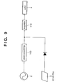
- the output from an AC/DC converter 100 that receives commercial power 2 and the output from a solar cell 3 are connected, and the DC power thus obtained is converted into AC power by an inverter 110 and supplied to a load 4 , as shown in FIG. 9.
- Such a system form can be regarded as a simple “load” from the viewpoint of preventing any reverse power flow to the commercial power system. For this reason, when deregulation about electric power greatly progresses in the future, individuals can freely use such a solar power generation system.
- the capacity of the load 4 is limited by the capacity of the inverter 110 .
- no measures are taken against unnecessary current leakage of the solar cell 3 due to the stray capacitance to ground, i.e., no device for safety use of the solar cell 3 is disclosed.
- FIG. 9 Another example that may make it possible to freely use a system as a “load” is an AC interconnection system which prevents any reverse power flow.
- commercial power and AC power from a power generator are connected without any conversion and supplied to a load, and the power generator is stopped upon detecting reverse power flow from the power generator to the commercial power system, using a protective relay for detecting reverse power to the commercial power.
- the limitation on the load capacity due to the output inverter 110 is not present, unlike the arrangement shown in FIG. 9, though the commercial power and power generator parallelly supply power to the load. For this reason, along with an increase in power generated by the power generator, a usable load capacity may exceed the rated load capacity to cause a load current beyond the rated value to flow, resulting in danger.
- the present invention has been made to solve these problems, and has as its object to provide an AC interconnection apparatus capable of easily, safely, and efficiently using a solar cell and a control method therefor.
- an AC interconnection apparatus of the present invention comprising the structures as follows.
- An AC interconnection apparatus for supplying to a load both AC power from a commercial power system and an output from a solar cell, comprising: an inverter for converting the output from the solar cell into AC power; a current detector arranged between the load and an AC connection point for connecting the AC input from the commercial power system and the AC output from the inverter to detect a current flowing to the load; and control means for obtaining load power applied to the load on the basis of a voltage value at the AC connection point and the current value detected by the current detector and controlling the output of the inverter on the basis of the load power and the output power of said inverter.
- a control method for an AC interconnection apparatus for supplying to a load both AC power from a commercial power system and an output from a solar cell comprising: a current detection step of detecting a current flowing to the load between the load and an AC connection point for connecting the AC input from the commercial power system and an AC output from an inverter for converting the output from the solar cell into AC power; and a control step of obtaining load power applied to the load on the basis of a voltage value at the AC connection point and the current value detected in the current detection step and controlling the output of the inverter on the basis of the load power and the output power of the inverter.
- FIG. 1 is a block diagram showing the arrangement of an AC interconnection apparatus according to the first embodiment of the present invention
- FIG. 2 is a view showing the outer appearance of the AC interconnection apparatus according to the embodiment of the present invention.
- FIG. 3 is a flow chart for explaining reverse power flow preventing operation by a controller of the AC interconnection apparatus according to the first embodiment
- FIG. 4 is a flow chart for explaining load current breaking operation by the controller of the AC interconnection apparatus according to the first embodiment
- FIG. 5 is a block diagram showing the arrangement of an AC interconnection apparatus according to the second embodiment of the present invention.
- FIG. 6 is a flow chart for explaining reverse power flow preventing operation by a controller of the AC interconnection apparatus according to the second embodiment
- FIG. 7 is a flow chart for explaining load current breaking operation by the controller of the AC interconnection apparatus according to the second embodiment
- FIG. 8 is a block diagram showing the arrangement of an AC interconnection apparatus according to the third embodiment of the present invention.
- FIG. 9 is a view for explaining a prior art.
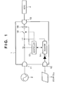
- FIG. 1 shows the arrangement of an AC interconnection apparatus 1 according to the first embodiment
- FIG. 2 shows the outer appearance of the apparatus.
- the AC interconnection apparatus 1 has a shape like a so-called table tap and has a plug-shaped connection terminal 11 to a commercial power system, a wall-socket-shaped (receptacle-shaped) load connection terminal 13 , and a solar cell connection terminal 12 having a shape different from the terminal 11 .
- the solar cell connection terminal 12 has a shape different from the terminal 11 to prevent any connection error, i.e., for safety.
- the terminals can have various shapes as far as they prevent any connection error. It is preferable that the terminal 12 has a different shape from the terminal 13 in the same point as the above described reason. Instead of using these terminals, a screwed terminal may be used. For practical use, however, connectors are preferably used, as in this embodiment.
- a system-interconnection inverter 14 a well-known sine-wave PWM inverter (incorporating a commercial insulating transformer) formed from a boosting chopper and full-bridge circuit is used.
- a method called high-frequency insulation using a high-frequency transformer may be used.
- the transformer can be made compact, and it is very preferable for this embodiment.
- Many methods are known as a method of controlling the inverter 14 , and a detailed description thereof will be omitted.
- many system interconnection inverters for solar power generation employ a control method called “instantaneous current control”.
- an “output current reference waveform” is input, and a switch circuit is controlled such that the reference waveform matches a current waveform to be actually output.
- Output power is determined by the amplitude and the phase difference from the system voltage. Since the inverter is often used at a power factor of 1 by fixing the phase difference to 0, it can be regarded that the output is proportional to the amplitude.
- the inverter 14 also has a maximum power tracking function and a control function of maintaining the input voltage from a solar cell 3 , when the output from the solar cell 3 is maximized.
- a controller 15 of the inverter 14 normally incorporates a function of detecting the output current and output power of the inverter 14 . In this embodiment, reverse power flow preventing operation is performed using this function.
- the capacity of the inverter 14 is 50 W, though it is appropriately selected in accordance with the capacity of the solar cell 3 connected. If the inverter 14 has a large capacity, the capacity of the usable solar cell 3 can also be increased. However, a necessary and minimum capacity is preferable because a large capacity inevitably causes an increase in size and cost of the apparatus.
- the solar cell 3 As the solar cell 3 , a crystal-based solar cell (output power: 50 W, output voltage: 16 V) is used. When such a low-voltage module is used, the safety for human body and the like can be increased. Especially, since a low-voltage-output solar cell with an output voltage lower than 30 V is excluded from electric equipment to which the Electricity Utilities Industry Law applies, the breakdown voltage can also be made low, and as a result, cost reduction can be expected. Additionally, it is generally supposed that such a low-voltage solar cell rarely causes an electrical shock as compared to a high-voltage solar cell and is therefore easy to handle for end users who have no special knowledge.
- an electric bulb 60 W
- a commercial power system a 100-V/60-Hz system is used. They are not particularly limited to the above load and system and can be appropriately selected as needed.
- the load 4 can directly receive power from the commercial power system 2 , unlike the DC interconnection apparatus shown in FIG. 9.
- the capacity of the load 4 can be set to the full rated current determined by the receptacle shapes shown in FIG. 2 or the thickness of an electrical wire. For example, when the shapes of this embodiment are selected, the rated capacity is 15 A to 20 A, so a load of 2 kVA can be connected.
- an inverter having a capacity of 2 kVA is required to drive a load of 2 kVA, resulting in a bulky apparatus.
- a current detector 16 As a current detector 16 , a normal current transformer that is often used is used. The set position is between an AC connection point 17 and the load connection terminal 13 , as shown in FIG. 1. Unless the current detector 16 is set at this position, it cannot directly detect the load current. To detect the current, many known devices such as a device using a Hall element can be selected. As a breaker 18 , a commercially available breaker or power relay can be used. A compact power relay for a power circuit is used here.
- the controller 15 controls the inverter 14 or other switch circuits, and a well-known one-chip microcomputer or sequencer can be used.
- a well-known one-chip microcomputer or sequencer can be used as the controller 15 .
- the power supply voltage of the controller 15 is obtained from a point Vs. How to obtain the power supply voltage is not particularly limited. The voltage at the connection point Vs is also used to detect the voltage of the commercial power system, which is necessary for power calculation.
- FIG. 3 shows an example of reverse power flow preventing operation of this embodiment.
- FIG. 3 is a flow chart for explaining reverse power flow preventing operation by the controller of the AC interconnection apparatus 1 according to the first embodiment.
- step S 1 the voltage of the commercial power system, which is obtained from the connection point Vs, is detected.
- step S 2 the load current is detected by the current detector 16 .
- step S 3 load power PL is calculated from these voltage and current values.
- step S 4 The flow advances to step S 4 to obtain output power Pi of the inverter 14 from the inverter 14 .
- step S 5 input power from the commercial power system is calculated as the difference between the load power PL and the output power Pi of the inverter 14 .
- step S 6 it is checked whether the input power (PL-Pi) obtained in step S 5 is less than a predetermined value (e.g., 0).
- step S 6 the flow advances to step S 7 to decrease the output current of the inverter 14 by a predetermined amount. This operation is repeated until the power input from the commercial power system becomes equal to or more than the predetermined value in step S 6 .
- the current detector 16 is arranged between the AC connection point 17 and the load connection terminal 13 .
- the process of calculating the input commercial power from the output of the inverter 14 and the power of the load 4 is necessary.
- the object “reverse power flow prevention” can be achieved.
- the single current detector 16 suffices, resulting in simple arrangement of the AC interconnection apparatus 1 .
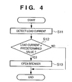
- FIG. 4 is a flow chart for explaining load current control by the controller of the AC interconnection apparatus 1 according to the first embodiment.
- step S 11 the load current flowing to the load 4 is detected by the current detector 16 .
- step S 12 it is determined whether the load current exceeds a predetermined value. If YES in step S 12 , the flow advances to step S 13 to open the breaker 18 to execute breaking operation.
- the solar cell 3 is insulated from the commercial power system. Hence, any unnecessary operation of the electrical leakage breaker can be prevented. This will be briefly described below.
- the AC interconnection apparatus 1 of this embodiment which can be connected to the solar cell 3 and used without taking the presence of such undefined stray capacitance into consideration, is very convenient for people who have no special knowledge.
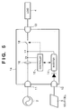
- An AC interconnection apparatus 1 a according to the second embodiment of the present invention has the arrangement shown in FIG. 5.
- the second embodiment is different from the first embodiment in the position of a current detector 16 .
- the current detector 16 is arranged between an AC connection point 17 and an input terminal 11 of a commercial power system 2 .
- the input/output current at the terminal 11 can be directly measured.
- the components shown in FIG. 5 are the same as in the above-described first embodiment (FIG. 1), and a detailed description thereof will be omitted. Operation different from the first embodiment will be described below.
- FIG. 6 is a flow chart showing reverse power flow preventing operation by a controller 15 of the AC interconnection apparatus 1 a according to the second embodiment of the present invention.
- step S 21 the current value of the commercial power system is detected by the current detector 16 .
- step S 22 the voltage value of the commercial power system at a connection point Vs is obtained.
- step S 23 input power PL is calculated from the current value detected in step S 21 and the system voltage Vs.
- step S 24 it is checked whether the power value PL is negative or is less than a predetermined value in consideration of a slight measurement error and the like. If YES in step S 24 , the flow advances to step S 25 to decrease the output current and amplitude instruction value of an inverter 14 , thereby suppressing the output of the inverter 14 .
- the amplitude instruction value is gradually decreased by a predetermined amount until no reverse power flow is observed.
- the output of the inverter 14 may be stopped as needed.
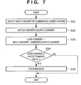
- FIG. 7 is a flow chart showing processing of controlling a load current by the controller 15 of the AC interconnection apparatus 1 a according to the second embodiment of the present invention by detecting a load over-current.
- step S 31 the input current from the commercial power system is measured by the current detector 16 .
- step S 32 the output current of the inverter 14 is detected.
- step S 33 a load current flowing to a load 4 is obtained from the sum of the input current obtained in step S 31 and the output current of the inverter 14 obtained in step S 32 .
- step S 34 it is checked whether the load current has a predetermined value or more. If YES in step S 34 , the flow advances to step S 35 to open a breaker 18 to break the current flowing to the load 4 .
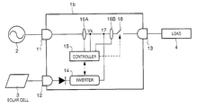
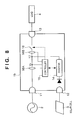
- FIG. 8 is a block diagram showing the arrangement of an AC interconnection apparatus 1 b according to the third embodiment of the present invention.
- the same reference numerals as in the above-described embodiments denote the same parts in FIG. 8, and a description thereof will be omitted.
- two current detectors 16 A and 16 B in FIG. 8 are used.
- the load current and the input/output current of the commercial power system can be directly measured.
- load current breaking operation by the load over-current can be executed as in the above-described flow chart of FIG. 4.
- Reverse power flow preventing operation can be executed according to the flow chart shown in FIG. 6.
- An inverter 14 need not have a function of detecting the output current or output power, and the structure of the inverter 14 can be simplified.
Abstract
An AC interconnection apparatus has an input terminal for a commercial power system, a connection terminal to a solar cell, an output terminal connected to a load, an inverter for converting the output voltage of the solar cell into an AC voltage, and a current detector arranged on the load side of an AC connection point for connecting the AC output from the inverter and the commercial power. When a power value calculated on the basis of a current detection value by the current detector and the voltage of the commercial power system is less than the output power of the inverter, the output of the inverter is suppressed, thereby suppressing reverse power flow to the commercial power system. When the current value detected by the current detector exceeds a predetermined value, power supply to the load is stopped using a breaker.
Description
- The present invention relates to an AC interconnection solar power generation apparatus and control method therefor.
- An example of the use form of a solar power generation system is a DC interconnection system disclosed in Japanese Patent Laid-Open No. 5-108176. In this system, the output from an AC/
DC converter 100 that receivescommercial power 2 and the output from asolar cell 3 are connected, and the DC power thus obtained is converted into AC power by aninverter 110 and supplied to aload 4, as shown in FIG. 9. Such a system form can be regarded as a simple “load” from the viewpoint of preventing any reverse power flow to the commercial power system. For this reason, when deregulation about electric power greatly progresses in the future, individuals can freely use such a solar power generation system. - In the prior art, however, the capacity of the
load 4 is limited by the capacity of theinverter 110. In addition, no measures are taken against unnecessary current leakage of thesolar cell 3 due to the stray capacitance to ground, i.e., no device for safety use of thesolar cell 3 is disclosed. - Another example that may make it possible to freely use a system as a “load” is an AC interconnection system which prevents any reverse power flow. Unlike the above-described system, commercial power and AC power from a power generator are connected without any conversion and supplied to a load, and the power generator is stopped upon detecting reverse power flow from the power generator to the commercial power system, using a protective relay for detecting reverse power to the commercial power. In this prior art, the limitation on the load capacity due to the
output inverter 110 is not present, unlike the arrangement shown in FIG. 9, though the commercial power and power generator parallelly supply power to the load. For this reason, along with an increase in power generated by the power generator, a usable load capacity may exceed the rated load capacity to cause a load current beyond the rated value to flow, resulting in danger. - The present invention has been made to solve these problems, and has as its object to provide an AC interconnection apparatus capable of easily, safely, and efficiently using a solar cell and a control method therefor.
- It is another object of the present invention to provide an AC interconnection apparatus capable of preventing any reverse power flow to a commercial power system even when power generated by a solar cell increases in an apparatus which supplies both commercial power and AC power from the solar cell to a load, and a control method therefor.
- It is still another object of the present invention to provide an AC interconnection apparatus capable of preventing any overpower to a load in an apparatus which supplies both commercial power and AC power from a solar cell to the load, and a control method therefor.
- In order to achieve the above described objects, an AC interconnection apparatus of the present invention comprising the structures as follows.
- An AC interconnection apparatus for supplying to a load both AC power from a commercial power system and an output from a solar cell, comprising: an inverter for converting the output from the solar cell into AC power; a current detector arranged between the load and an AC connection point for connecting the AC input from the commercial power system and the AC output from the inverter to detect a current flowing to the load; and control means for obtaining load power applied to the load on the basis of a voltage value at the AC connection point and the current value detected by the current detector and controlling the output of the inverter on the basis of the load power and the output power of said inverter.
- In order to achieve the above described objects, a control method for an AC interconnection apparatus of the present invention comprising the steps as follows.
- A control method for an AC interconnection apparatus for supplying to a load both AC power from a commercial power system and an output from a solar cell, comprising: a current detection step of detecting a current flowing to the load between the load and an AC connection point for connecting the AC input from the commercial power system and an AC output from an inverter for converting the output from the solar cell into AC power; and a control step of obtaining load power applied to the load on the basis of a voltage value at the AC connection point and the current value detected in the current detection step and controlling the output of the inverter on the basis of the load power and the output power of the inverter.
- Other features and advantages of the present invention will be apparent from the following description taken in conjunction with the accompanying drawings, in which like reference characters designate the same or similar parts throughout the figures thereof.
- The accompanying drawings, which are incorporated in and constitute a part of the specification, illustrate embodiments of the invention and, together with the description, serve to explain the principles of the invention.
- FIG. 1 is a block diagram showing the arrangement of an AC interconnection apparatus according to the first embodiment of the present invention;
- FIG. 2 is a view showing the outer appearance of the AC interconnection apparatus according to the embodiment of the present invention;
- FIG. 3 is a flow chart for explaining reverse power flow preventing operation by a controller of the AC interconnection apparatus according to the first embodiment;
- FIG. 4 is a flow chart for explaining load current breaking operation by the controller of the AC interconnection apparatus according to the first embodiment;
- FIG. 5 is a block diagram showing the arrangement of an AC interconnection apparatus according to the second embodiment of the present invention;
- FIG. 6 is a flow chart for explaining reverse power flow preventing operation by a controller of the AC interconnection apparatus according to the second embodiment;
- FIG. 7 is a flow chart for explaining load current breaking operation by the controller of the AC interconnection apparatus according to the second embodiment;
- FIG. 8 is a block diagram showing the arrangement of an AC interconnection apparatus according to the third embodiment of the present invention; and
- FIG. 9 is a view for explaining a prior art.
- The preferred embodiments of the present invention will be described below in detail with reference to the accompanying drawings.
- <First Embodiment>
- [Outer Appearance and Connection Terminal]
- FIG. 1 shows the arrangement of an AC interconnection apparatus 1 according to the first embodiment, and FIG. 2 shows the outer appearance of the apparatus.
- As shown in FIG. 2, the AC interconnection apparatus 1 according to this embodiment has a shape like a so-called table tap and has a plug-
shaped connection terminal 11 to a commercial power system, a wall-socket-shaped (receptacle-shaped)load connection terminal 13, and a solarcell connection terminal 12 having a shape different from theterminal 11. The solarcell connection terminal 12 has a shape different from theterminal 11 to prevent any connection error, i.e., for safety. The terminals can have various shapes as far as they prevent any connection error. It is preferable that theterminal 12 has a different shape from theterminal 13 in the same point as the above described reason. Instead of using these terminals, a screwed terminal may be used. For practical use, however, connectors are preferably used, as in this embodiment. - [System Interconnection Inverter]
- As a system-interconnection inverter 14, a well-known sine-wave PWM inverter (incorporating a commercial insulating transformer) formed from a boosting chopper and full-bridge circuit is used. As an insulating method, a method called high-frequency insulation using a high-frequency transformer may be used. In the high-frequency insulation, the transformer can be made compact, and it is very preferable for this embodiment. Many methods are known as a method of controlling the
inverter 14, and a detailed description thereof will be omitted. Generally, many system interconnection inverters for solar power generation employ a control method called “instantaneous current control”. Briefly speaking, in this control method, an “output current reference waveform” is input, and a switch circuit is controlled such that the reference waveform matches a current waveform to be actually output. Output power is determined by the amplitude and the phase difference from the system voltage. Since the inverter is often used at a power factor of 1 by fixing the phase difference to 0, it can be regarded that the output is proportional to the amplitude. Theinverter 14 also has a maximum power tracking function and a control function of maintaining the input voltage from asolar cell 3, when the output from thesolar cell 3 is maximized. - A
controller 15 of theinverter 14 normally incorporates a function of detecting the output current and output power of theinverter 14. In this embodiment, reverse power flow preventing operation is performed using this function. The capacity of theinverter 14 is 50 W, though it is appropriately selected in accordance with the capacity of thesolar cell 3 connected. If theinverter 14 has a large capacity, the capacity of the usablesolar cell 3 can also be increased. However, a necessary and minimum capacity is preferable because a large capacity inevitably causes an increase in size and cost of the apparatus. - [Solar Cell]
- As the
solar cell 3, a crystal-based solar cell (output power: 50 W, output voltage: 16 V) is used. When such a low-voltage module is used, the safety for human body and the like can be increased. Especially, since a low-voltage-output solar cell with an output voltage lower than 30 V is excluded from electric equipment to which the Electricity Utilities Industry Law applies, the breakdown voltage can also be made low, and as a result, cost reduction can be expected. Additionally, it is generally supposed that such a low-voltage solar cell rarely causes an electrical shock as compared to a high-voltage solar cell and is therefore easy to handle for end users who have no special knowledge. - [Load and Commercial Power System]
- As an
experimental load 4, an electric bulb (60 W) is used. As a commercial power system, a 100-V/60-Hz system is used. They are not particularly limited to the above load and system and can be appropriately selected as needed. In this embodiment, theload 4 can directly receive power from thecommercial power system 2, unlike the DC interconnection apparatus shown in FIG. 9. Hence, the capacity of theload 4 can be set to the full rated current determined by the receptacle shapes shown in FIG. 2 or the thickness of an electrical wire. For example, when the shapes of this embodiment are selected, the rated capacity is 15 A to 20 A, so a load of 2 kVA can be connected. To the contrary, in the above-described conventional DC interconnection apparatus, an inverter having a capacity of 2 kVA is required to drive a load of 2 kVA, resulting in a bulky apparatus. - [Current Detector and Breaker]
- As a
current detector 16, a normal current transformer that is often used is used. The set position is between anAC connection point 17 and theload connection terminal 13, as shown in FIG. 1. Unless thecurrent detector 16 is set at this position, it cannot directly detect the load current. To detect the current, many known devices such as a device using a Hall element can be selected. As abreaker 18, a commercially available breaker or power relay can be used. A compact power relay for a power circuit is used here. - [Controller]
- The
controller 15 controls theinverter 14 or other switch circuits, and a well-known one-chip microcomputer or sequencer can be used. In this embodiment, as thecontroller 15, a commercially available one-chip microcomputer is used. However, any change can be made if the object of the present invention can be achieved. In this embodiment, the power supply voltage of thecontroller 15 is obtained from a point Vs. How to obtain the power supply voltage is not particularly limited. The voltage at the connection point Vs is also used to detect the voltage of the commercial power system, which is necessary for power calculation. - [Operation]
- {circle over (1)} Reverse Power Flow Preventing Operation (Reverse Power-flow Protection)
- The flow chart of FIG. 3 shows an example of reverse power flow preventing operation of this embodiment. FIG. 3 is a flow chart for explaining reverse power flow preventing operation by the controller of the AC interconnection apparatus 1 according to the first embodiment.
- First, in step S 1, the voltage of the commercial power system, which is obtained from the connection point Vs, is detected. In step S2, the load current is detected by the
current detector 16. In step S3, load power PL is calculated from these voltage and current values. The flow advances to step S4 to obtain output power Pi of theinverter 14 from theinverter 14. In step S5, input power from the commercial power system is calculated as the difference between the load power PL and the output power Pi of theinverter 14. In step S6, it is checked whether the input power (PL-Pi) obtained in step S5 is less than a predetermined value (e.g., 0). If YES in step S6, the flow advances to step S7 to decrease the output current of theinverter 14 by a predetermined amount. This operation is repeated until the power input from the commercial power system becomes equal to or more than the predetermined value in step S6. - In the first embodiment, the
current detector 16 is arranged between theAC connection point 17 and theload connection terminal 13. Hence, to prevent any reverse power flow, the process of calculating the input commercial power from the output of theinverter 14 and the power of theload 4 is necessary. However, with this process, the object “reverse power flow prevention” can be achieved. In addition, the singlecurrent detector 16 suffices, resulting in simple arrangement of the AC interconnection apparatus 1. - {circle over (2)} Load Over-current Breaking Operation (Over Load Protection)
- As described above, in the first embodiment, since the current flowing to the
load 4 is directly measured, it is easy to detect a load over-current and break the current when the load over-current has a predetermined value or more. The operation flow is shown in FIG. 4. - FIG. 4 is a flow chart for explaining load current control by the controller of the AC interconnection apparatus 1 according to the first embodiment.
- First, in step S 11, the load current flowing to the
load 4 is detected by thecurrent detector 16. In step S12, it is determined whether the load current exceeds a predetermined value. If YES in step S12, the flow advances to step S13 to open thebreaker 18 to execute breaking operation. - It is important here that since the
current detector 16 is arranged between theAC connection point 17 and theload connection terminal 13, the load current can be controlled by such considerably simple control operation. - {circle over (3)} Checking Resistance about Stray Capacitance to Ground
- In the arrangement shown in FIG. 1, the
solar cell 3 is insulated from the commercial power system. Hence, any unnecessary operation of the electrical leakage breaker can be prevented. This will be briefly described below. - As is known, in a solar power generation system in which the power input terminal from the solar cell is uninsulated from the commercial power system, and the stray capacitance to ground is large, generally, an unnecessary leakage current flows. As an experiment, in the AC interconnection apparatus 1 having the arrangement shown in FIG. 1, a 100-μF capacitor was connected between the
solar cell 3 and ground. When the presence/absence of a leakage current was checked, no leakage current was observed. From this viewpoint, in the apparatus of this embodiment, since no leakage current flows, the electrical leakage breaker does not perform any unnecessary operation, and the safety is very high. Since the stray capacitance changes depending on the shape or installation form of thesolar cell 3 or the weather, the AC interconnection apparatus 1 of this embodiment, which can be connected to thesolar cell 3 and used without taking the presence of such undefined stray capacitance into consideration, is very convenient for people who have no special knowledge. - <Second Embodiment>
- The second embodiment of the present invention will be described below.
- An
AC interconnection apparatus 1 a according to the second embodiment of the present invention has the arrangement shown in FIG. 5. The second embodiment is different from the first embodiment in the position of acurrent detector 16. In the second embodiment; thecurrent detector 16 is arranged between anAC connection point 17 and aninput terminal 11 of acommercial power system 2. When thecurrent detector 16 is arranged at this position, the input/output current at the terminal 11 can be directly measured. The components shown in FIG. 5 are the same as in the above-described first embodiment (FIG. 1), and a detailed description thereof will be omitted. Operation different from the first embodiment will be described below. - [Operation]
- {circle over (1)} Reverse Power Flow Preventing Operation (Reverse Power-flow Protection)
- FIG. 6 is a flow chart showing reverse power flow preventing operation by a
controller 15 of theAC interconnection apparatus 1 a according to the second embodiment of the present invention. - First, in step S 21, the current value of the commercial power system is detected by the
current detector 16. In step S22, the voltage value of the commercial power system at a connection point Vs is obtained. In step S23, input power PL is calculated from the current value detected in step S21 and the system voltage Vs. In step S24, it is checked whether the power value PL is negative or is less than a predetermined value in consideration of a slight measurement error and the like. If YES in step S24, the flow advances to step S25 to decrease the output current and amplitude instruction value of aninverter 14, thereby suppressing the output of theinverter 14. The amplitude instruction value is gradually decreased by a predetermined amount until no reverse power flow is observed. The output of theinverter 14 may be stopped as needed. When thecurrent detector 16 is arranged at the position shown in FIG. 5 of the second embodiment, the reverse power flow preventing operation can be more simplified. - {circle over (2)} Load Over-current Breaking Operation (Overload Protection)
- FIG. 7 is a flow chart showing processing of controlling a load current by the
controller 15 of theAC interconnection apparatus 1 a according to the second embodiment of the present invention by detecting a load over-current. - First, in step S 31, the input current from the commercial power system is measured by the
current detector 16. In step S32, the output current of theinverter 14 is detected. In step S33, a load current flowing to aload 4 is obtained from the sum of the input current obtained in step S31 and the output current of theinverter 14 obtained in step S32. In step S34, it is checked whether the load current has a predetermined value or more. If YES in step S34, the flow advances to step S35 to open abreaker 18 to break the current flowing to theload 4. - To prevent any reverse power flow when the
current detector 16 is set at the position of the second embodiment, the process of calculating the load current from the input current from the commercial power system and the output current of theinverter 14 is necessary. However, with this process, the object “load over-current breaking” can be achieved, and the safety increases. In addition, the singlecurrent detector 16 suffices, resulting in simple arrangement of the AC interconnection apparatus. - <Third Embodiment>
- The third embodiment of the present invention will be described below.
- FIG. 8 is a block diagram showing the arrangement of an
AC interconnection apparatus 1 b according to the third embodiment of the present invention. The same reference numerals as in the above-described embodiments denote the same parts in FIG. 8, and a description thereof will be omitted. - In the third embodiment, as shown in FIG. 8, two current detectors ( 16A and 16B in FIG. 8) are used. With this arrangement, the load current and the input/output current of the commercial power system can be directly measured. Hence, load current breaking operation by the load over-current can be executed as in the above-described flow chart of FIG. 4. Reverse power flow preventing operation can be executed according to the flow chart shown in FIG. 6. An
inverter 14 need not have a function of detecting the output current or output power, and the structure of theinverter 14 can be simplified. - Although the embodiments have been independently described above, the present invention is not limited to this, and an appropriate combination of the arrangements of the embodiments is also incorporated in the present invention.
- The present invention is not limited to the above embodiments and various changes and modifications can be made within the spirit and scope of the present invention. Therefore, to apprise the public of the scope of the present invention, the following claims are made.
Claims (26)
1. An AC interconnection apparatus for supplying to a load both AC power from a commercial power system and an output from a solar cell, comprising:
an inverter for converting the output from the solar cell into AC power;
a current detector arranged between the load and an AC connection point for connecting the AC input from the commercial power system and the AC output from said inverter to detect a current flowing to the load; and
control means for obtaining load power applied to the load on the basis of a voltage value at the AC connection point and the current value detected by said current detector and controlling the output of said inverter on the basis of the load power and the output power of said inverter.
2. The apparatus according to claim 1 , wherein said control means suppresses the output of said inverter when the load power becomes less than the output power of said inverter.
3. The apparatus according to claim 1 , wherein a shape of a terminal for receiving the AC power from the commercial power system is different from that of a terminal for receiving the output from the solar cell.
4. The apparatus according to claim 1 , further comprising a circuit breaker arranged between the AC connection point and the load,
wherein said control means stops power supply to the load using said circuit breaker when the current value detected by said current detector has not less than a predetermined value.
5. The apparatus according to claim 1 , wherein the output from the solar cell and the commercial power system are insulated from each other.
6. An AC interconnection apparatus for supplying to a load both AC power from a commercial power system and an output from a solar cell, comprising:
an inverter for converting the output from the solar cell into AC power;
a current detector arranged on the AC input side of an AC connection point for connecting the AC input from the commercial power system and the AC output from said inverter to detect a current supplied from the commercial power system; and
control means for controlling the output of said inverter on the basis of a current value from the commercial power system, which is calculated on the basis of the detection value from said current detector.
7. The apparatus according to claim 6 , wherein said control means suppresses the output of said inverter when the current value from the commercial power system becomes less than a predetermined value.
8. The apparatus according to claim 6 , further comprising a circuit breaker arranged between the AC connection point and the load,
wherein said control means stops power supply to the load using said circuit breaker when the load power has not less than a predetermined value.
9. The apparatus according to claim 6 , wherein a shape of a terminal for receiving the AC power from the commercial power system is different from that of a terminal for receiving the output from the solar cell.
10. The apparatus according to claim 6 , wherein the output from the solar cell and the commercial power system are insulated from each other.
11. An AC interconnection apparatus for supplying to a load both AC power from a commercial power system and an output from a solar cell, comprising:
an inverter for converting the output from the solar cell into AC power;
a first current detector arranged on the AC input side of an AC connection point for connecting the AC input from the commercial power system and the AC output from said inverter;
a second current detector arranged between the AC connection point and the load; and
control means for controlling the output of said inverter in accordance with a detection value from said first current detector and controlling power supply to the load in accordance with a detection value from said second current detector.
12. The apparatus according to claim 11 , wherein said control means obtains a power value from the commercial power system on the basis of the detection value from said first current detector and suppresses the output of said inverter when the power value from becomes less than a predetermined value.
13. The apparatus according to claim 11 , further comprising a circuit breaker arranged between the AC connection point and the load,
wherein said control means stops power supply to the load using said circuit breaker when the current value detected by said second current detector has not less than a predetermined value.
14. The apparatus according to claim 11 , wherein the output from the solar cell and the commercial power system are insulated from each other.
15. The apparatus according to claim 11 , wherein a shape of a terminal for receiving the AC power from the commercial power system is different from that of a terminal for receiving the output from the solar cell.
16. A control method for an AC interconnection apparatus for supplying to a load both AC power from a commercial power system and an output from a solar cell, comprising:
a current detection step of detecting a current flowing to the load between the load and an AC connection point for connecting the AC input from the commercial power system and an AC output from an inverter for converting the output from the solar cell into AC power; and
a control step of obtaining load power applied to the load on the basis of a voltage value at the AC connection point and the current value detected in the current detection step and controlling the output of the inverter on the basis of the load power and the output power of the inverter.
17. The method according to claim 16 , wherein in the control step, control is performed to suppress the output of the inverter when the load power becomes less than the output power of the inverter.
18. The method according to claim 16 , wherein in the control step, when the current value detected in the current detection step has not less than a predetermined value, power supply to the load is stopped.
19. A control method for an AC interconnection apparatus for supplying to a load both AC power from a commercial power system and an output from a solar cell, comprising:
a current detection step of detecting a current supplied from the commercial power system on an AC input side of an AC connection point for connecting the AC input from the commercial power system and an AC output from an inverter for converting the output from the solar cell into AC power; and
a control step of controlling the output of the inverter on the basis of a power value from the commercial power system, which is calculated on the basis of the detection value in the current detection step.
20. The method according to claim 19 , wherein in the control step, the output of the inverter is suppressed when the power value from the commercial power system becomes less than a predetermined value.
21. The method according to claim 19 , wherein in the control step, when the load power has not less than a predetermined value, power supply to the load is stopped.
22. A control method for an AC interconnection apparatus for supplying to a load both AC power from a commercial power system and an output from a solar cell, comprising:
a first current detection step of detecting a current on an AC input side of an AC connection point for connecting the AC input from the commercial power system and an AC output from an inverter for converting the output from the solar cell into AC power;
a second current detection step of detecting a current between the AC connection point and the load; and
a control step of controlling the output of the inverter in accordance with a detection value in the first current detection step and controlling power supply to the load in accordance with a detection value in the second current detection step.
23. The method according to claim 22 , wherein in the control step, a power value from the commercial power system is obtained on the basis of the detection value in the first current detection step, and the output of the inverter is suppressed when the power value from becomes less than a predetermined value.
24. The method according to claim 22 , wherein in the control step, when the current value detected in the second current detection step has not less than a predetermined value, power supply to the load is stopped.
25. An AC interconnection apparatus for supplying AC power to a load from a commercial power system and/or an output from a solar cell, comprising:
a plug-shaped connection terminal for the commercial power system;
a receptacle-shaped load connection terminal; and
a solar cell connection terminal having a shape different from the plug-shaped connection terminal for the commercial power system.
26. An apparatus according to claim 25 , wherein said solar cell connection terminal has a shape different from said receptacle-shaped load connection terminal.
Priority Applications (1)
| Application Number | Priority Date | Filing Date | Title |
|---|---|---|---|
| US10/435,052 US6761581B2 (en) | 2000-10-31 | 2003-05-12 | AC interconnection apparatus for supplying AC power from a commercial power system and from a solar cell |
Applications Claiming Priority (6)
| Application Number | Priority Date | Filing Date | Title |
|---|---|---|---|
| JP2000332897 | 2000-10-31 | ||
| JP2000-332897 | 2000-10-31 | ||
| JP2001328065A JP2002204531A (en) | 2000-10-31 | 2001-10-25 | Ac-interconnecting device and control method thereof |
| JP2001-328065 | 2001-10-25 | ||
| US09/984,391 US6605881B2 (en) | 2000-10-25 | 2001-10-30 | AC interconnection apparatus supplying AC power from a commercial power system and from a solar cell |
| US10/435,052 US6761581B2 (en) | 2000-10-31 | 2003-05-12 | AC interconnection apparatus for supplying AC power from a commercial power system and from a solar cell |
Related Parent Applications (1)
| Application Number | Title | Priority Date | Filing Date |
|---|---|---|---|
| US09/984,391 Division US6605881B2 (en) | 2000-10-25 | 2001-10-30 | AC interconnection apparatus supplying AC power from a commercial power system and from a solar cell |
Publications (2)
| Publication Number | Publication Date |
|---|---|
| US20030197429A1 true US20030197429A1 (en) | 2003-10-23 |
| US6761581B2 US6761581B2 (en) | 2004-07-13 |
Family
ID=26603162
Family Applications (2)
| Application Number | Title | Priority Date | Filing Date |
|---|---|---|---|
| US09/984,391 Expired - Fee Related US6605881B2 (en) | 2000-10-25 | 2001-10-30 | AC interconnection apparatus supplying AC power from a commercial power system and from a solar cell |
| US10/435,052 Expired - Fee Related US6761581B2 (en) | 2000-10-31 | 2003-05-12 | AC interconnection apparatus for supplying AC power from a commercial power system and from a solar cell |
Family Applications Before (1)
| Application Number | Title | Priority Date | Filing Date |
|---|---|---|---|
| US09/984,391 Expired - Fee Related US6605881B2 (en) | 2000-10-25 | 2001-10-30 | AC interconnection apparatus supplying AC power from a commercial power system and from a solar cell |
Country Status (2)
| Country | Link |
|---|---|
| US (2) | US6605881B2 (en) |
| JP (1) | JP2002204531A (en) |
Cited By (4)
| Publication number | Priority date | Publication date | Assignee | Title |
|---|---|---|---|---|
| US20070150366A1 (en) * | 2005-12-23 | 2007-06-28 | Sharp Electronics Corporation | Integrated solar agent business model |
| US20100327655A1 (en) * | 2008-02-26 | 2010-12-30 | Shinichiro Okamoto | Power supply apparatus |
| WO2011012272A3 (en) * | 2009-07-30 | 2011-06-30 | Loeffler Martin | Circuit assembly for current steering |
| US20120091801A1 (en) * | 2009-06-25 | 2012-04-19 | Panasonic Electric Works Co., Ltd. | Power supply apparatus |
Families Citing this family (69)
| Publication number | Priority date | Publication date | Assignee | Title |
|---|---|---|---|---|
| US6889122B2 (en) * | 1998-05-21 | 2005-05-03 | The Research Foundation Of State University Of New York | Load controller and method to enhance effective capacity of a photovoltaic power supply using a dynamically determined expected peak loading |
| US7733069B2 (en) * | 2000-09-29 | 2010-06-08 | Canon Kabushiki Kaisha | Power converting apparatus and power generating apparatus |
| JP2002204531A (en) * | 2000-10-31 | 2002-07-19 | Canon Inc | Ac-interconnecting device and control method thereof |
| JP2002318162A (en) * | 2001-02-01 | 2002-10-31 | Canon Inc | Detection method and protection device of malfunction, and estimation method and estimation device of temperature |
| JP2002354678A (en) * | 2001-05-29 | 2002-12-06 | Canon Inc | Power generating device, and its control method |
| JP4585774B2 (en) * | 2003-03-07 | 2010-11-24 | キヤノン株式会社 | Power conversion device and power supply device |
| CN100433493C (en) * | 2003-05-07 | 2008-11-12 | 株式会社荏原电产 | Power supply including system interconnection inverter |
| US7104847B2 (en) * | 2004-02-26 | 2006-09-12 | Briggs & Stratton Power Products Group, Llc | Electric power system and method of operating the same |
| JP4160919B2 (en) * | 2004-03-24 | 2008-10-08 | シャープ株式会社 | Inverter device |
| JP2005312138A (en) * | 2004-04-19 | 2005-11-04 | Canon Inc | Power controller, power generation system and power system |
| US7193872B2 (en) * | 2005-01-28 | 2007-03-20 | Kasemsan Siri | Solar array inverter with maximum power tracking |
| US7408268B1 (en) | 2005-08-04 | 2008-08-05 | Magnetek, S.P.A. | Anti-islanding method and system for distributed power generation systems |
| US20080169704A1 (en) * | 2006-09-11 | 2008-07-17 | Coffman Electrical Equipment Co. | Advanced mobile power system |
| WO2008112080A1 (en) * | 2007-03-07 | 2008-09-18 | Greenray, Inc. | Data acquisition apparatus and methodology for self-diagnosis of ac modules |
| US10468993B2 (en) * | 2007-05-17 | 2019-11-05 | Enphase Energy, Inc. | Inverter for use in photovoltaic module |
| US7755916B2 (en) | 2007-10-11 | 2010-07-13 | Solarbridge Technologies, Inc. | Methods for minimizing double-frequency ripple power in single-phase power conditioners |
| US20090224681A1 (en) * | 2008-03-10 | 2009-09-10 | S & A Solar Technologies, Inc. | Hybrid Solar Powered and Grid Powered Lighting System |
| TW201008078A (en) * | 2008-08-08 | 2010-02-16 | Wistron Corp | A holding device with charging function |
| US8319373B2 (en) | 2008-12-26 | 2012-11-27 | Pichkur Yaroslav A | System, socket and plug apparatus for DC power distribution and usage |
| US8212406B2 (en) * | 2008-12-26 | 2012-07-03 | Yaroslav A. Pichkur | System, socket and plug apparatus for DC power distribution and usage |
| US8435056B2 (en) * | 2009-04-16 | 2013-05-07 | Enphase Energy, Inc. | Apparatus for coupling power generated by a photovoltaic module to an output |
| US8279642B2 (en) | 2009-07-31 | 2012-10-02 | Solarbridge Technologies, Inc. | Apparatus for converting direct current to alternating current using an active filter to reduce double-frequency ripple power of bus waveform |
| JP2011072099A (en) * | 2009-09-24 | 2011-04-07 | Panasonic Electric Works Co Ltd | Power supply system |
| US8207637B2 (en) | 2009-10-09 | 2012-06-26 | Solarbridge Technologies, Inc. | System and apparatus for interconnecting an array of power generating assemblies |
| US8253274B2 (en) * | 2009-10-10 | 2012-08-28 | Yang Pan | Power supply system for electrical appliance |
| US8462518B2 (en) | 2009-10-12 | 2013-06-11 | Solarbridge Technologies, Inc. | Power inverter docking system for photovoltaic modules |
| KR101649268B1 (en) * | 2009-10-14 | 2016-08-18 | 삼성전자주식회사 | Switching mode power supply and fusing apparatus |
| US8824178B1 (en) | 2009-12-31 | 2014-09-02 | Solarbridge Technologies, Inc. | Parallel power converter topology |
| US9806445B2 (en) | 2010-01-25 | 2017-10-31 | Enphase Energy, Inc. | Method and apparatus for interconnecting distributed power sources |
| EP2529450A4 (en) | 2010-01-25 | 2014-10-22 | Enphase Energy Inc | Method and apparatus for interconnecting distributed power sources |
| US20130000342A1 (en) * | 2010-01-29 | 2013-01-03 | Carrier Corporation | Solar power assisted transport refrigeration systems, transport refrigeration units and methods for same |
| JP5672087B2 (en) * | 2010-04-02 | 2015-02-18 | オムロン株式会社 | Control apparatus and control method |
| US9160408B2 (en) | 2010-10-11 | 2015-10-13 | Sunpower Corporation | System and method for establishing communication with an array of inverters |
| US8279649B2 (en) | 2010-10-11 | 2012-10-02 | Solarbridge Technologies, Inc. | Apparatus and method for controlling a power inverter |
| US8503200B2 (en) | 2010-10-11 | 2013-08-06 | Solarbridge Technologies, Inc. | Quadrature-corrected feedforward control apparatus and method for DC-AC power conversion |
| CN101958572B (en) * | 2010-10-12 | 2013-01-02 | 友达光电股份有限公司 | Power circuit and power management method thereof |
| US9118213B2 (en) | 2010-11-24 | 2015-08-25 | Kohler Co. | Portal for harvesting energy from distributed electrical power sources |
| US8842454B2 (en) | 2010-11-29 | 2014-09-23 | Solarbridge Technologies, Inc. | Inverter array with localized inverter control |
| US9467063B2 (en) | 2010-11-29 | 2016-10-11 | Sunpower Corporation | Technologies for interleaved control of an inverter array |
| JPWO2012086825A1 (en) * | 2010-12-21 | 2014-06-05 | 日本電気株式会社 | Charging apparatus and charging method |
| US7977818B1 (en) | 2011-01-25 | 2011-07-12 | Wahl Eric R | Safety device for plug and play solar energy system |
| JP5730101B2 (en) * | 2011-03-31 | 2015-06-03 | 株式会社神戸製鋼所 | Method for controlling local power system with power generation system and local power system |
| US8193788B2 (en) | 2011-04-27 | 2012-06-05 | Solarbridge Technologies, Inc. | Method and device for controlling a configurable power supply to provide AC and/or DC power output |
| US8611107B2 (en) | 2011-04-27 | 2013-12-17 | Solarbridge Technologies, Inc. | Method and system for controlling a multi-stage power inverter |
| US9065354B2 (en) | 2011-04-27 | 2015-06-23 | Sunpower Corporation | Multi-stage power inverter for power bus communication |
| US8922185B2 (en) | 2011-07-11 | 2014-12-30 | Solarbridge Technologies, Inc. | Device and method for global maximum power point tracking |
| CN103828228A (en) | 2011-07-18 | 2014-05-28 | 恩菲斯能源公司 | Resilient mounting assembly for photovoltaic modules |
| US20130093554A1 (en) * | 2011-10-14 | 2013-04-18 | Enphase Energy, Inc. | Method and apparatus for reducing pressure effects on an encapsulated device |
| US8284574B2 (en) | 2011-10-17 | 2012-10-09 | Solarbridge Technologies, Inc. | Method and apparatus for controlling an inverter using pulse mode control |
| JP5872353B2 (en) * | 2012-03-28 | 2016-03-01 | 京セラ株式会社 | Energy management system and energy management method |
| USD707632S1 (en) | 2012-06-07 | 2014-06-24 | Enphase Energy, Inc. | Trunk connector |
| USD708143S1 (en) | 2012-06-07 | 2014-07-01 | Enphase Energy, Inc. | Drop cable connector |
| US9276635B2 (en) | 2012-06-29 | 2016-03-01 | Sunpower Corporation | Device, system, and method for communicating with a power inverter using power line communications |
| USD734653S1 (en) | 2012-11-09 | 2015-07-21 | Enphase Energy, Inc. | AC module mounting bracket |
| US9564835B2 (en) | 2013-03-15 | 2017-02-07 | Sunpower Corporation | Inverter communications using output signal |
| US9584044B2 (en) | 2013-03-15 | 2017-02-28 | Sunpower Corporation | Technologies for converter topologies |
| ITVR20130099A1 (en) | 2013-04-24 | 2014-10-25 | Francesco Ulian | EQUIPMENT FOR EMISSION OF ELECTRICITY |
| DE102013109608B4 (en) | 2013-09-03 | 2019-01-10 | Sma Solar Technology Ag | Method and feed-in control for feeding electrical power into a line branch |
| CN103956745B (en) * | 2014-04-29 | 2016-06-08 | 武汉大学 | A kind of loading demand changes adaptive photovoltaic power and controls system and method |
| WO2016109690A1 (en) * | 2015-01-02 | 2016-07-07 | Q Factory 33 Llc | Circuit breaker with current monitoring |
| JP5896096B1 (en) * | 2015-09-01 | 2016-03-30 | 東芝三菱電機産業システム株式会社 | Power generation equipment and power generation control device |
| CN106899078A (en) * | 2015-12-18 | 2017-06-27 | 三亚中兴软件有限责任公司 | Method for controlling power supply and device |
| CN106026360A (en) * | 2016-06-26 | 2016-10-12 | 潘炳松 | Dual-power-supply power distribution system |
| JP6709743B2 (en) * | 2017-01-30 | 2020-06-17 | 京セラ株式会社 | Power converter and control method thereof |
| JP6797073B2 (en) * | 2017-05-09 | 2020-12-09 | 大阪瓦斯株式会社 | Operation control device and power generation equipment |
| CN109494788B (en) * | 2018-11-08 | 2020-09-29 | 珠海格力电器股份有限公司 | Photovoltaic electrical appliance system and voltage protection value control method and device thereof |
| JP7385382B2 (en) * | 2019-06-21 | 2023-11-22 | 新電元工業株式会社 | Power generation system, power conditioner and its reverse power flow prevention method |
| CN110611368B (en) * | 2019-06-25 | 2021-12-24 | 南京巨鲨显示科技有限公司 | Power-off prevention power supply and design method thereof |
| JP7253725B2 (en) * | 2020-01-30 | 2023-04-07 | パナソニックIpマネジメント株式会社 | power generation system |
Citations (8)
| Publication number | Priority date | Publication date | Assignee | Title |
|---|---|---|---|---|
| US4862141A (en) * | 1987-11-05 | 1989-08-29 | Jordal Robert L | Integrated smoke and intrusion alarm system |
| US5493155A (en) * | 1991-04-22 | 1996-02-20 | Sharp Kabushiki Kaisha | Electric power supply system |
| US5548504A (en) * | 1992-10-19 | 1996-08-20 | Canon Kabushiki Kaisha | Power line linking apparatus for linking a power generator to a commercial power line |
| US6137280A (en) * | 1999-01-22 | 2000-10-24 | Science Applications International Corporation | Universal power manager with variable buck/boost converter |
| US20010004198A1 (en) * | 1999-12-15 | 2001-06-21 | Hirotsugu Matsuyama | Battery pack and charge circuit therefor |
| US6313438B1 (en) * | 2000-11-07 | 2001-11-06 | George W. Emerick, Jr. | Solar heated sleeping bag |
| US6530085B1 (en) * | 1998-09-16 | 2003-03-04 | Webtv Networks, Inc. | Configuration for enhanced entertainment system control |
| US6605881B2 (en) * | 2000-10-25 | 2003-08-12 | Canon Kabushiki Kaisha | AC interconnection apparatus supplying AC power from a commercial power system and from a solar cell |
Family Cites Families (26)
| Publication number | Priority date | Publication date | Assignee | Title |
|---|---|---|---|---|
| JPS6154820A (en) * | 1984-08-23 | 1986-03-19 | シャープ株式会社 | Dc/ac converter of photogenerator system |
| JPH0521949Y2 (en) * | 1985-12-02 | 1993-06-04 | ||
| DE69216658T2 (en) | 1991-02-25 | 1997-08-07 | Canon Kk | Device and method for connecting electrical components |
| EP0501361B1 (en) | 1991-02-25 | 2002-05-15 | Canon Kabushiki Kaisha | Electrical connecting member and method of manufacturing the same |
| JPH05108176A (en) | 1991-10-17 | 1993-04-30 | Tonen Corp | Solar battery power source |
| US5592074A (en) | 1992-06-26 | 1997-01-07 | Canon Kabushiki Kaisha | Battery power supply system |
| US5627737A (en) * | 1993-09-13 | 1997-05-06 | Sanyo Electric Co., Ltd. | Power inverter for use in system interconnection |
| US5669987A (en) | 1994-04-13 | 1997-09-23 | Canon Kabushiki Kaisha | Abnormality detection method, abnormality detection apparatus, and solar cell power generating system using the same |
| JP3271730B2 (en) | 1994-04-28 | 2002-04-08 | キヤノン株式会社 | Power generation system charge control device |
| JPH08275390A (en) | 1995-03-29 | 1996-10-18 | Canon Inc | Method and apparatus for controlling charging and discharging, and power generating system having such apparatus |
| JPH0916277A (en) | 1995-04-24 | 1997-01-17 | Canon Inc | Direct-current power supply system with solar battery, and its operating method |
| TW336271B (en) * | 1995-06-13 | 1998-07-11 | Sanyo Electric Co | Solar generator and an air conditioner with such a solar generator |
| JP3270303B2 (en) | 1995-07-26 | 2002-04-02 | キヤノン株式会社 | Battery power supply device characteristic measuring device and measuring method |
| JP3382434B2 (en) | 1995-09-22 | 2003-03-04 | キヤノン株式会社 | Battery power supply voltage control device and voltage control method |
| JP3368124B2 (en) | 1995-10-26 | 2003-01-20 | キヤノン株式会社 | Overcharge prevention circuit |
| JP3327774B2 (en) * | 1996-06-03 | 2002-09-24 | キヤノン株式会社 | Solar power system |
| JP3352334B2 (en) | 1996-08-30 | 2002-12-03 | キヤノン株式会社 | Solar cell power controller |
| JP3554116B2 (en) | 1996-09-06 | 2004-08-18 | キヤノン株式会社 | Power control device and solar power generation system using the same |
| JP3565470B2 (en) | 1997-06-13 | 2004-09-15 | キヤノン株式会社 | Ground fault protection device and operation method thereof, photovoltaic power generation system having the same, and inverter for photovoltaic power generation system having the same |
| US5929538A (en) * | 1997-06-27 | 1999-07-27 | Abacus Controls Inc. | Multimode power processor |
| JP4076721B2 (en) * | 1997-11-24 | 2008-04-16 | エイチ. ウィルス、ロバート | Isolated power-proof method and apparatus for distributed generation |
| JP3026189B2 (en) | 1998-04-24 | 2000-03-27 | 西芝電機株式会社 | Control device for private power generator |
| US6429546B1 (en) * | 1998-11-20 | 2002-08-06 | Georgia Tech Research Corporation | Systems and methods for preventing islanding of grid-connected electrical power systems |
| US6184593B1 (en) * | 1999-07-29 | 2001-02-06 | Abb Power T&D Company Inc. | Uninterruptible power supply |
| JP2001161032A (en) | 1999-12-01 | 2001-06-12 | Canon Inc | System interconnection power conditioner and power generating system using the same |
| JP2002112553A (en) | 2000-09-29 | 2002-04-12 | Canon Inc | Power converter, its control method, and generator |
-
2001
- 2001-10-25 JP JP2001328065A patent/JP2002204531A/en not_active Abandoned
- 2001-10-30 US US09/984,391 patent/US6605881B2/en not_active Expired - Fee Related
-
2003
- 2003-05-12 US US10/435,052 patent/US6761581B2/en not_active Expired - Fee Related
Patent Citations (8)
| Publication number | Priority date | Publication date | Assignee | Title |
|---|---|---|---|---|
| US4862141A (en) * | 1987-11-05 | 1989-08-29 | Jordal Robert L | Integrated smoke and intrusion alarm system |
| US5493155A (en) * | 1991-04-22 | 1996-02-20 | Sharp Kabushiki Kaisha | Electric power supply system |
| US5548504A (en) * | 1992-10-19 | 1996-08-20 | Canon Kabushiki Kaisha | Power line linking apparatus for linking a power generator to a commercial power line |
| US6530085B1 (en) * | 1998-09-16 | 2003-03-04 | Webtv Networks, Inc. | Configuration for enhanced entertainment system control |
| US6137280A (en) * | 1999-01-22 | 2000-10-24 | Science Applications International Corporation | Universal power manager with variable buck/boost converter |
| US20010004198A1 (en) * | 1999-12-15 | 2001-06-21 | Hirotsugu Matsuyama | Battery pack and charge circuit therefor |
| US6605881B2 (en) * | 2000-10-25 | 2003-08-12 | Canon Kabushiki Kaisha | AC interconnection apparatus supplying AC power from a commercial power system and from a solar cell |
| US6313438B1 (en) * | 2000-11-07 | 2001-11-06 | George W. Emerick, Jr. | Solar heated sleeping bag |
Cited By (8)
| Publication number | Priority date | Publication date | Assignee | Title |
|---|---|---|---|---|
| US20070150366A1 (en) * | 2005-12-23 | 2007-06-28 | Sharp Electronics Corporation | Integrated solar agent business model |
| US7844499B2 (en) | 2005-12-23 | 2010-11-30 | Sharp Electronics Corporation | Integrated solar agent business model |
| US20110047048A1 (en) * | 2005-12-23 | 2011-02-24 | Sharp Electronics Corporation | Integrated solar agent business model |
| US8315912B2 (en) | 2005-12-23 | 2012-11-20 | Sharp Electronics Corporation | Integrated solar agent business model |
| US20100327655A1 (en) * | 2008-02-26 | 2010-12-30 | Shinichiro Okamoto | Power supply apparatus |
| US20120091801A1 (en) * | 2009-06-25 | 2012-04-19 | Panasonic Electric Works Co., Ltd. | Power supply apparatus |
| US9142958B2 (en) * | 2009-06-25 | 2015-09-22 | Panasonic Corporation | Power supply apparatus |
| WO2011012272A3 (en) * | 2009-07-30 | 2011-06-30 | Loeffler Martin | Circuit assembly for current steering |
Also Published As
| Publication number | Publication date |
|---|---|
| US20020067628A1 (en) | 2002-06-06 |
| JP2002204531A (en) | 2002-07-19 |
| US6605881B2 (en) | 2003-08-12 |
| US6761581B2 (en) | 2004-07-13 |
Similar Documents
| Publication | Publication Date | Title |
|---|---|---|
| US6605881B2 (en) | AC interconnection apparatus supplying AC power from a commercial power system and from a solar cell | |
| US6838611B2 (en) | Solar battery module and power generation apparatus | |
| US10554148B2 (en) | Device and method for premagnetization of a power transformer in a converter system | |
| JP4463963B2 (en) | Grid interconnection device | |
| US8467160B2 (en) | Bipolar DC to AC power converter with DC ground fault interrupt | |
| US9257829B2 (en) | Grounding apparatus | |
| WO2010116806A1 (en) | Power conversion device | |
| JP3245504B2 (en) | Inverter device | |
| US10797485B2 (en) | Power conditioner, power supply system, and current control method | |
| CN113161995A (en) | Apparatus and method for fault current detection | |
| US10014679B2 (en) | Electrical switching apparatus including alternating current electronic trip circuit with arc fault detection circuit and power supply | |
| Carminati et al. | DC and AC ground fault analysis in LVDC microgrids with energy storage systems | |
| CN104901273B (en) | Rccb | |
| JP4405654B2 (en) | Power converter and power generator | |
| JP2010110056A (en) | Power distribution system | |
| CN114400913A (en) | Photovoltaic inverter and photovoltaic grid-connected inverter system applying same | |
| JPH07213072A (en) | Grounding protective device for single-phase three-wire inverter | |
| JP2002142383A (en) | Direct-current link device | |
| JP2003018740A (en) | Dc ground fault detector and interconnected system power generating apparatus | |
| GB2586343A (en) | Power electronic converter with a ground fault detection unit that shares a common ground with both DC ports and AC ports | |
| JP3957557B2 (en) | Inverter device and grid-connected power generator | |
| CN215897283U (en) | Parallel resonance induction heating system and leakage protection circuit thereof | |
| CN114252669B (en) | Device for generating series arc harmonic signals | |
| JP2002165461A (en) | Transformerless inverter power supply | |
| CN117713187A (en) | Inverter and switch detection method |
Legal Events
| Date | Code | Title | Description |
|---|---|---|---|
| FEPP | Fee payment procedure |
Free format text: PAYOR NUMBER ASSIGNED (ORIGINAL EVENT CODE: ASPN); ENTITY STATUS OF PATENT OWNER: LARGE ENTITY |
|
| FPAY | Fee payment |
Year of fee payment: 4 |
|
| REMI | Maintenance fee reminder mailed | ||
| LAPS | Lapse for failure to pay maintenance fees | ||
| STCH | Information on status: patent discontinuation |
Free format text: PATENT EXPIRED DUE TO NONPAYMENT OF MAINTENANCE FEES UNDER 37 CFR 1.362 |
|
| FP | Lapsed due to failure to pay maintenance fee |
Effective date: 20120713 |