US20030196613A1 - Method and device for cooling a motor vehicle engine - Google Patents
Method and device for cooling a motor vehicle engine Download PDFInfo
- Publication number
- US20030196613A1 US20030196613A1 US10/181,962 US18196202A US2003196613A1 US 20030196613 A1 US20030196613 A1 US 20030196613A1 US 18196202 A US18196202 A US 18196202A US 2003196613 A1 US2003196613 A1 US 2003196613A1
- Authority
- US
- United States
- Prior art keywords
- temperature
- actuator
- fluid
- branch
- cooling
- Prior art date
- Legal status (The legal status is an assumption and is not a legal conclusion. Google has not performed a legal analysis and makes no representation as to the accuracy of the status listed.)
- Granted
Links
Images


Classifications
-
- F—MECHANICAL ENGINEERING; LIGHTING; HEATING; WEAPONS; BLASTING
- F02—COMBUSTION ENGINES; HOT-GAS OR COMBUSTION-PRODUCT ENGINE PLANTS
- F02M—SUPPLYING COMBUSTION ENGINES IN GENERAL WITH COMBUSTIBLE MIXTURES OR CONSTITUENTS THEREOF
- F02M31/00—Apparatus for thermally treating combustion-air, fuel, or fuel-air mixture
- F02M31/02—Apparatus for thermally treating combustion-air, fuel, or fuel-air mixture for heating
- F02M31/04—Apparatus for thermally treating combustion-air, fuel, or fuel-air mixture for heating combustion-air or fuel-air mixture
- F02M31/042—Combustion air
-
- F—MECHANICAL ENGINEERING; LIGHTING; HEATING; WEAPONS; BLASTING
- F01—MACHINES OR ENGINES IN GENERAL; ENGINE PLANTS IN GENERAL; STEAM ENGINES
- F01P—COOLING OF MACHINES OR ENGINES IN GENERAL; COOLING OF INTERNAL-COMBUSTION ENGINES
- F01P7/00—Controlling of coolant flow
- F01P7/14—Controlling of coolant flow the coolant being liquid
- F01P7/16—Controlling of coolant flow the coolant being liquid by thermostatic control
- F01P7/167—Controlling of coolant flow the coolant being liquid by thermostatic control by adjusting the pre-set temperature according to engine parameters, e.g. engine load, engine speed
-
- F—MECHANICAL ENGINEERING; LIGHTING; HEATING; WEAPONS; BLASTING
- F02—COMBUSTION ENGINES; HOT-GAS OR COMBUSTION-PRODUCT ENGINE PLANTS
- F02M—SUPPLYING COMBUSTION ENGINES IN GENERAL WITH COMBUSTIBLE MIXTURES OR CONSTITUENTS THEREOF
- F02M26/00—Engine-pertinent apparatus for adding exhaust gases to combustion-air, main fuel or fuel-air mixture, e.g. by exhaust gas recirculation [EGR] systems
- F02M26/13—Arrangement or layout of EGR passages, e.g. in relation to specific engine parts or for incorporation of accessories
- F02M26/22—Arrangement or layout of EGR passages, e.g. in relation to specific engine parts or for incorporation of accessories with coolers in the recirculation passage
- F02M26/33—Arrangement or layout of EGR passages, e.g. in relation to specific engine parts or for incorporation of accessories with coolers in the recirculation passage controlling the temperature of the recirculated gases
-
- F—MECHANICAL ENGINEERING; LIGHTING; HEATING; WEAPONS; BLASTING
- F01—MACHINES OR ENGINES IN GENERAL; ENGINE PLANTS IN GENERAL; STEAM ENGINES
- F01P—COOLING OF MACHINES OR ENGINES IN GENERAL; COOLING OF INTERNAL-COMBUSTION ENGINES
- F01P11/00—Component parts, details, or accessories not provided for in, or of interest apart from, groups F01P1/00 - F01P9/00
- F01P11/02—Liquid-coolant filling, overflow, venting, or draining devices
- F01P11/028—Deaeration devices
-
- F—MECHANICAL ENGINEERING; LIGHTING; HEATING; WEAPONS; BLASTING
- F01—MACHINES OR ENGINES IN GENERAL; ENGINE PLANTS IN GENERAL; STEAM ENGINES
- F01P—COOLING OF MACHINES OR ENGINES IN GENERAL; COOLING OF INTERNAL-COMBUSTION ENGINES
- F01P7/00—Controlling of coolant flow
- F01P7/14—Controlling of coolant flow the coolant being liquid
- F01P2007/146—Controlling of coolant flow the coolant being liquid using valves
-
- F—MECHANICAL ENGINEERING; LIGHTING; HEATING; WEAPONS; BLASTING
- F01—MACHINES OR ENGINES IN GENERAL; ENGINE PLANTS IN GENERAL; STEAM ENGINES
- F01P—COOLING OF MACHINES OR ENGINES IN GENERAL; COOLING OF INTERNAL-COMBUSTION ENGINES
- F01P2023/00—Signal processing; Details thereof
-
- F—MECHANICAL ENGINEERING; LIGHTING; HEATING; WEAPONS; BLASTING
- F01—MACHINES OR ENGINES IN GENERAL; ENGINE PLANTS IN GENERAL; STEAM ENGINES
- F01P—COOLING OF MACHINES OR ENGINES IN GENERAL; COOLING OF INTERNAL-COMBUSTION ENGINES
- F01P2025/00—Measuring
- F01P2025/08—Temperature
-
- F—MECHANICAL ENGINEERING; LIGHTING; HEATING; WEAPONS; BLASTING
- F01—MACHINES OR ENGINES IN GENERAL; ENGINE PLANTS IN GENERAL; STEAM ENGINES
- F01P—COOLING OF MACHINES OR ENGINES IN GENERAL; COOLING OF INTERNAL-COMBUSTION ENGINES
- F01P2025/00—Measuring
- F01P2025/08—Temperature
- F01P2025/12—Cabin temperature
-
- F—MECHANICAL ENGINEERING; LIGHTING; HEATING; WEAPONS; BLASTING
- F01—MACHINES OR ENGINES IN GENERAL; ENGINE PLANTS IN GENERAL; STEAM ENGINES
- F01P—COOLING OF MACHINES OR ENGINES IN GENERAL; COOLING OF INTERNAL-COMBUSTION ENGINES
- F01P2025/00—Measuring
- F01P2025/08—Temperature
- F01P2025/13—Ambient temperature
-
- F—MECHANICAL ENGINEERING; LIGHTING; HEATING; WEAPONS; BLASTING
- F01—MACHINES OR ENGINES IN GENERAL; ENGINE PLANTS IN GENERAL; STEAM ENGINES
- F01P—COOLING OF MACHINES OR ENGINES IN GENERAL; COOLING OF INTERNAL-COMBUSTION ENGINES
- F01P2025/00—Measuring
- F01P2025/60—Operating parameters
-
- F—MECHANICAL ENGINEERING; LIGHTING; HEATING; WEAPONS; BLASTING
- F01—MACHINES OR ENGINES IN GENERAL; ENGINE PLANTS IN GENERAL; STEAM ENGINES
- F01P—COOLING OF MACHINES OR ENGINES IN GENERAL; COOLING OF INTERNAL-COMBUSTION ENGINES
- F01P2025/00—Measuring
- F01P2025/60—Operating parameters
- F01P2025/62—Load
-
- F—MECHANICAL ENGINEERING; LIGHTING; HEATING; WEAPONS; BLASTING
- F01—MACHINES OR ENGINES IN GENERAL; ENGINE PLANTS IN GENERAL; STEAM ENGINES
- F01P—COOLING OF MACHINES OR ENGINES IN GENERAL; COOLING OF INTERNAL-COMBUSTION ENGINES
- F01P2025/00—Measuring
- F01P2025/60—Operating parameters
- F01P2025/64—Number of revolutions
-
- F—MECHANICAL ENGINEERING; LIGHTING; HEATING; WEAPONS; BLASTING
- F01—MACHINES OR ENGINES IN GENERAL; ENGINE PLANTS IN GENERAL; STEAM ENGINES
- F01P—COOLING OF MACHINES OR ENGINES IN GENERAL; COOLING OF INTERNAL-COMBUSTION ENGINES
- F01P2025/00—Measuring
- F01P2025/60—Operating parameters
- F01P2025/66—Vehicle speed
-
- F—MECHANICAL ENGINEERING; LIGHTING; HEATING; WEAPONS; BLASTING
- F01—MACHINES OR ENGINES IN GENERAL; ENGINE PLANTS IN GENERAL; STEAM ENGINES
- F01P—COOLING OF MACHINES OR ENGINES IN GENERAL; COOLING OF INTERNAL-COMBUSTION ENGINES
- F01P2060/00—Cooling circuits using auxiliaries
- F01P2060/02—Intercooler
-
- F—MECHANICAL ENGINEERING; LIGHTING; HEATING; WEAPONS; BLASTING
- F01—MACHINES OR ENGINES IN GENERAL; ENGINE PLANTS IN GENERAL; STEAM ENGINES
- F01P—COOLING OF MACHINES OR ENGINES IN GENERAL; COOLING OF INTERNAL-COMBUSTION ENGINES
- F01P2060/00—Cooling circuits using auxiliaries
- F01P2060/04—Lubricant cooler
-
- F—MECHANICAL ENGINEERING; LIGHTING; HEATING; WEAPONS; BLASTING
- F01—MACHINES OR ENGINES IN GENERAL; ENGINE PLANTS IN GENERAL; STEAM ENGINES
- F01P—COOLING OF MACHINES OR ENGINES IN GENERAL; COOLING OF INTERNAL-COMBUSTION ENGINES
- F01P2060/00—Cooling circuits using auxiliaries
- F01P2060/08—Cabin heater
-
- F—MECHANICAL ENGINEERING; LIGHTING; HEATING; WEAPONS; BLASTING
- F01—MACHINES OR ENGINES IN GENERAL; ENGINE PLANTS IN GENERAL; STEAM ENGINES
- F01P—COOLING OF MACHINES OR ENGINES IN GENERAL; COOLING OF INTERNAL-COMBUSTION ENGINES
- F01P2060/00—Cooling circuits using auxiliaries
- F01P2060/10—Fuel manifold
-
- F—MECHANICAL ENGINEERING; LIGHTING; HEATING; WEAPONS; BLASTING
- F01—MACHINES OR ENGINES IN GENERAL; ENGINE PLANTS IN GENERAL; STEAM ENGINES
- F01P—COOLING OF MACHINES OR ENGINES IN GENERAL; COOLING OF INTERNAL-COMBUSTION ENGINES
- F01P7/00—Controlling of coolant flow
- F01P7/02—Controlling of coolant flow the coolant being cooling-air
- F01P7/04—Controlling of coolant flow the coolant being cooling-air by varying pump speed, e.g. by changing pump-drive gear ratio
- F01P7/048—Controlling of coolant flow the coolant being cooling-air by varying pump speed, e.g. by changing pump-drive gear ratio using electrical drives
-
- F—MECHANICAL ENGINEERING; LIGHTING; HEATING; WEAPONS; BLASTING
- F01—MACHINES OR ENGINES IN GENERAL; ENGINE PLANTS IN GENERAL; STEAM ENGINES
- F01P—COOLING OF MACHINES OR ENGINES IN GENERAL; COOLING OF INTERNAL-COMBUSTION ENGINES
- F01P7/00—Controlling of coolant flow
- F01P7/14—Controlling of coolant flow the coolant being liquid
- F01P7/16—Controlling of coolant flow the coolant being liquid by thermostatic control
- F01P7/164—Controlling of coolant flow the coolant being liquid by thermostatic control by varying pump speed
-
- F—MECHANICAL ENGINEERING; LIGHTING; HEATING; WEAPONS; BLASTING
- F02—COMBUSTION ENGINES; HOT-GAS OR COMBUSTION-PRODUCT ENGINE PLANTS
- F02M—SUPPLYING COMBUSTION ENGINES IN GENERAL WITH COMBUSTIBLE MIXTURES OR CONSTITUENTS THEREOF
- F02M26/00—Engine-pertinent apparatus for adding exhaust gases to combustion-air, main fuel or fuel-air mixture, e.g. by exhaust gas recirculation [EGR] systems
- F02M26/13—Arrangement or layout of EGR passages, e.g. in relation to specific engine parts or for incorporation of accessories
- F02M26/22—Arrangement or layout of EGR passages, e.g. in relation to specific engine parts or for incorporation of accessories with coolers in the recirculation passage
- F02M26/23—Layout, e.g. schematics
- F02M26/28—Layout, e.g. schematics with liquid-cooled heat exchangers
-
- Y—GENERAL TAGGING OF NEW TECHNOLOGICAL DEVELOPMENTS; GENERAL TAGGING OF CROSS-SECTIONAL TECHNOLOGIES SPANNING OVER SEVERAL SECTIONS OF THE IPC; TECHNICAL SUBJECTS COVERED BY FORMER USPC CROSS-REFERENCE ART COLLECTIONS [XRACs] AND DIGESTS
- Y02—TECHNOLOGIES OR APPLICATIONS FOR MITIGATION OR ADAPTATION AGAINST CLIMATE CHANGE
- Y02T—CLIMATE CHANGE MITIGATION TECHNOLOGIES RELATED TO TRANSPORTATION
- Y02T10/00—Road transport of goods or passengers
- Y02T10/10—Internal combustion engine [ICE] based vehicles
- Y02T10/12—Improving ICE efficiencies
Definitions
- the invention concerns a method and a device for cooling a motor vehicle engine.
- the invention concerns, more particularly, a cooling device comprising a hydraulic circuit of cooling fluid, associated with a pump for circulating it through the engine of the vehicle and different branches of the circuit.
- Thermal equipment of the vehicle can be arranged in the different branches of the circuit.
- Cooling systems are designed to ensure the resistance of the engines to the thermomechanical stresses resulting from combustion.
- complementary functions are implemented, beyond the main cooling of the engine, in order to improve the overall efficiency or to provide and guarantee benefits to vehicle users, such as, for example, the heating of the passenger compartment.
- the cooling systems are dimensioned using only operation points at maximum speed and full load of the engine, and are thus overdimensioned in the majority of usage cases of the vehicles.
- the operation parameters of the engine are not optimized, which leads to a degradation of its performances, such as an increased consumption, a high level of emission of pollutants, as well as a reduction in the heating and acoustic comfort of the vehicle.
- the document DE4033261 describes a cooling system for a combustion engine comprising a circuit of cooling liquid forming a loop with a radiator.
- the circuit comprises, in addition, a bypass parallel to the radiator that allows the fluid to return directly to the engine.
- the distribution of the cooling liquid between the radiator and the bypass is ensured by a thermostatic valve.
- An additional valve makes it possible to block the return of the fluid to the engine in order to accelerate the speed of the increase in temperature of the engine.
- a purpose of the present invention is to propose a method for cooling a motor vehicle engine, correcting all or a part of the disadvantages of the prior art mentioned above.
- the method for cooling a motor vehicle engine consists in regulating the volume and the flow rate of a cooling fluid in a hydraulic circuit provided with a branch equipped with an electronically controlled proportional actuator and provided with means forming direct return of fluid or bypass, and comprises a step of determining the temperature of the cooling fluid, a step of comparing the temperature determined with a first and a second specified threshold temperature, and a step of controlling the opening of the actuator, so that, when the liquid temperature is between the first and the second threshold temperatures, the degree to which the actuator is opened is at least temporarily proportional to the temperature of the cooling fluid.
- the method comprises a step of cutting off, or limiting to a specified leakage flow rate, the circulation of fluid in the bypass branch.
- Another purpose of the present invention is to propose a device for cooling a motor vehicle engine, correcting all or a part of the disadvantages of the prior art mentioned above.
- the device for cooling a motor vehicle engine of the type comprising a hydraulic circuit of cooling fluid, associated with a pump for circulating the fluid through the engine of the vehicle and different branches of the circuit, in which are arranged thermal equipment of the vehicle, at least some of the branches of the circuit being equipped with electronically controlled actuators to regulate the circulation of the fluid in these branches, the device comprising means for collecting information relating to the operation conditions of the vehicle, connected to means for controlling the operation of the actuators,.
- the circuit comprises a branch equipped with an electronically controlled proportional actuator and provided with means forming direct return of fluid or bypass, the information collection means being adapted to determine the temperature of the cooling fluid, so that, when the temperature of the fluid is between specified first and second threshold temperatures, the degree of opening of the actuator is at least temporarily proportional to the temperature of the cooling fluid.
- the invention may comprise one or more of the following characteristics:
- control means cut off, or limit to a specified leakage flow rate, the circulation of fluid in the bypass branch,
- control means control at least temporarily the opening of the actuator
- control means when the temperature of the fluid is lower than the first threshold temperature, the control means partially open the actuator so as to ensure a leakage flow rate in the bypass branch in the order of ⁇ fraction (1/50) ⁇ to 1 ⁇ 5 approximately of the maximum flow of the bypass branch,
- the opening of the actuator of the bypass branch increases when the temperature of the fluid increases and decreases when the temperature of the fluid decreases such that the curve representing the opening of the actuator as a function of the temperature of the fluid exhibits a hysteresis
- the increase in the opening of the actuator begins after the temperature of the liquid exceeds the first reference temperature by a specified first value
- the decrease in the opening of the actuator begins after the temperature of the liquid becomes lower than the second reference temperature by a specified first value
- the circuit comprises a branch equipped with an actuator and provided with means forming radiator, and when the temperature of the fluid is greater than the second threshold temperature, the control means control the actuator of the bypass branch as a function of the opening and closing of the actuator of the radiator branch, so as, on the one hand, to close the actuator of the bypass branch when the actuator of the radiator branch is opened, and, on the other hand, to open the actuator of the bypass branch when the actuator of the radiator branch is closed, the closings and openings of the actuator of the bypass branch being performed simultaneously, or with a specified temperature offset relative to the openings and closings of the actuator of the radiator branch,
- the actuator of the radiator branch is of the proportional type, and in that the opening of the actuator of the bypass branch is inversely proportional to the opening of the actuator of the radiator bypass hose,
- the device comprises ventilating means, or a “Motor Ventilation Unit”, adapted to cooperate with the means forming radiator, the control means ensuring the control of the ventilation means as a function of the temperature of the cooling liquid, in a manner so that the rotational speed of the ventilation means increases when the temperature of the cooling liquid increases,
- the increase in the rotational speed of the ventilation means is controlled as a function of the speed of variation of the temperature of the cooling liquid
- the rotational speed of the ventilating means as a function of the temperature of the cooling liquid is depicted by a line whose slope is proportional to the speed of variation of the temperature of the cooling liquid.
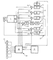
- FIG. 1 shows schematically the structure and the operation of a first example of embodiment of the cooling device according to the invention
- FIG. 2 shows a second embodiment of the cooling device according to the invention
- FIG. 3 shows, on a same graph, an example of variation, in the course of time t, of the temperature T of the cooling liquid and a first threshold temperature T 1 ,
- FIG. 4 shows an example of variation of the temperature Th of the engine lubrication oil as a function of tine t, as well as the signal that represents the opened O and closed F states of the electronically controlled actuator of the first branch of the circuit,
- FIG. 5 shows the opened O and closed F states of the actuator of the degassing branch as a function of the temperature T of the cooling liquid
- FIG. 6 shows an example of variation of the period P of the control signal of the actuator of the degassing branch as a function of the temperature T of the cooling liquid
- FIG. 7 shows the opened state of the bypass valve as a function of the temperature T of the cooling liquid
- FIG. 8 shows schematically an example of coupling of the opening of the bypass valve as a function of the opening of the valve of a radiator
- FIG. 9 shows two examples of variation of the rotational speed of a motor ventilation unit, as a function of the variation of the temperature T of the cooling liquid,
- FIG. 1 shows a preferred example of embodiment of a cooling device according to the invention.
- the cooling device comprises a hydraulic circuit 2 containing a cooling fluid.
- a hydraulic pump 3 is associated with the circuit 2 in order to ensure the circulation of the fluid through the engine 1 and different branches 4 , 5 , 6 , 7 , 8 , 44 of the circuit 2 .
- the pump 3 is a pump of the mechanical type, however, the use of an electric pump can also be envisioned.
- the branches 4 , 5 , 6 , 7 , 8 , 44 of the circuit 2 are supplied with cooling liquid from a box 122 , or “Water Outlet Box” (WOB).
- the box 122 which is affixed to the engine 1 , and preferably to the engine block 1 , ensures the collection of the cooling liquid having circulated in the engine 1 .
- the cooling liquid that has circulated in the branches is itself recovered by a water input collector 23 before its recirculation in the engine 1 .
- the branches 4 , 5 , 6 , 7 , 8 , 44 of the circuit 2 are equipped with respective electronically controlled actuators 14 , 15 , 16 , 17 , 18 , 29 for regulating the circulation of the fluid in these branches.
- the electronically controlled actuators are, for example, solenoid valves.
- the device comprises means 22 for collecting information relating to the operation conditions of the vehicle.
- the collection means 22 are connected to the means 19 for controlling the operation of at least one part of the actuators 14 , 15 , 16 , 17 , 18 , 29 , in order to regulate the volume and the flow rate of the fluid circulating in the hydraulic circuit 2 so as to optimize the operation of the engine.
- the control means 19 or information processing unit can comprise any appropriate computer 20 such as, for example, an “Intelligent Coupling Box” (ICB) of a known type.
- the computer 20 is associated with means 21 for storing information comprising, for example, a programmable memory and/or a read-only memory.
- the computer 20 is also connected to means 22 for collecting information relating to the operation conditions of the vehicle, comprising, for example, various sensors or other computers such as an engine control computer.
- the information collection means 22 are adapted to determine at least one of the following parameters: the speed of the engine, the torque of the engine, the speed of the vehicle, the temperature of the engine lubrication oil, the temperature of the cooling liquid of the engine, the temperature of the exhaust gases of the engine, the temperature of the air outside the vehicle and the temperature inside the passenger compartment.
- the various items of information regarding the operation conditions of the vehicle are processed and analyzed by the computer 20 , in order to control the operation of the actuators 14 , 15 , 16 , 17 , 18 , 29 , and possibly, the operation of the pump 3 .
- the flow rate or the volume of cooling liquid allowed or not allowed to circulate in the different branches 4 , 5 , 6 , 7 , 8 , 44 of the circuit 2 is a function of the heated state of the engine 1 .
- it is possible to define three states of the engine 1 a first state in which the engine is referred to as “cold”, a second in which the engine 1 is referred to as “hot” and a third state referred to as “intermediate” between the hot and cold states.
- the thermal state of the engine 1 is characterized as a function of the temperature T of the cooling liquid, preferably at the outlet of the engine 1 .
- the state of the engine 1 is referred to as cold.
- the state of the engine 1 is referred to as hot.
- the state of the engine 1 is referred to as intermediate.
- the first threshold temperature T 1 and/or the second threshold temperature T 2 can be fixed or variable values specified as a function of the type of the engine 1 .
- the first threshold temperature T 1 and/or the second threshold temperature T 2 are variables as a function of the type of engine 1 and of at least one operation parameter of the engine 1 .
- the first threshold temperature T 1 and/or the second threshold temperature T 2 are functions of the average power Pm supplied by the engine 1 .
- the control means 19 cooperate with the collection means 22 in order to calculate the average instantaneous power Pm supplied by the engine 1 .
- the control means 19 then calculate the first threshold temperature T 1 and/or the second threshold temperature T 2 , as a function of the average instantaneous power Pm and of a specified modeling of the operation of the engine 1 .
- the modeling of the engine defines the cold, hot and intermediate states (first threshold temperature T 1 and second threshold temperature T 2 ) as a function of the average power Pm supplied by the engine.
- N is the instantaneous speed of the engine in rpm
- C is the instantaneous torque of the engine in N.m.
- the values of the speed N and the torque C can be measured by the information collection means 22 , i.e., by appropriate sensors.
- the speed N of the engine is approximately between 0 and 6000 rpm
- the torque C is approximately between 0 and 350 N.m.
- the control means 19 then calculate the power P(t) supplied by the engine at the time t and the average power Pm(t) supplied by the engine at the time t.
- Pm(t ⁇ 1) is the average power at the time (t ⁇ 1).
- Pm(t ⁇ 1) is the average power at the time (t ⁇ 1)
- P(t) is the instantaneous power at the time t
- c and k are weighting coefficients.
- the computer 19 and/or the information storage means 21 can contain the modeling of the operation of the engine 1 , defining its cold state, hot state, and intermediate state (first threshold temperature T 1 and second threshold temperature T 2 ) as a function of the average power Pm.
- first threshold temperature T 1 and second threshold temperature T 2 are, for example, polynomial functions.
- the first threshold temperature T 1 is thus, in general, a decreasing function of the average power.
- the first threshold temperature T 1 can vary between 20 and 60 degrees approximately, and preferably between 30 and 50 degrees.
- the second threshold temperature T 2 can itself vary between 60 and 100 degrees approximately. However, the threshold temperature T 2 is generally substantially constant around the value of 80 degrees.
- control means 19 cooperate with the information collection means 22 in order to compare the temperature T of the cooling liquid with the two threshold temperatures T 1 and T 2 .
- the value of the first threshold temperature T 1 can be fixed by the control means 19 as soon as the measured temperature T of the cooling liquid reaches the first threshold temperature T 1 .
- FIG. 3 illustrates, in a same graph, an example of variation in the course of the time t: of the temperature T of the cooling liquid, and of the first threshold temperature T 1 (Pm) which is a function of the average power.
- T and T 1 (Pm) it is noted that, for a given average power, from the time when the temperature T of the fluid reaches the first threshold value T1, this first threshold temperature T 1 varies slightly around a constant T 1 f.
- the circuit 2 comprises a first branch 8 equipped with a first electronically controlled actuator 18 and in which is arranged a water/oil exchanger 13 .
- the first actuator 18 is of the “all or nothing” type.
- the control means 19 cooperate with the collection means 22 , in order to control the opening or closing of the first actuator 18 , so as, on the one hand, to accelerate the speed of the increase in the temperature of the oil, and, on the other hand, to regulate the temperature of the oil around a specified reference temperature Tr.
- the control means 19 limit, and preferably stop, the circulation of the fluid in the first branch 8 .
- the control means 19 regulate the temperature of the oil around the reference temperature Tr.
- the reference temperature Tr of the oil corresponds to the optimum operation temperature of the oil.
- the reference temperature Tr which depends on the type of oil, is traditionally between 120 and 140 degrees approximately, and is preferably equal to 130 degrees approximately.
- the collection means 22 comprise means for measuring the temperature of the lubricating oil, such as an appropriate sensor.
- FIG. 4 illustrates an example of variation of the temperature Th of the oil as a function of the time t.
- a square pulse signal symbolizing the opened O and closed F states of the actuator 18 of the first branch 8 is shown.
- the upper notches of the square pulse signal show the opening times O of the actuator 18 .
- the lower notches of the square pulse signal show the closing times F of the same actuator 18 .
- the control means 19 ensure the opening of the actuator 18 and thus the circulation of the fluid in the first branch 8 . Further, when the temperature Th of the oil is lower by a value ⁇ Ta than the reference temperature Tr, the control means 19 close the actuator 18 and thus stop the circulation of the fluid in the first branch 8 .
- the temperature differentials ⁇ Ta that trigger the openings O and closings F of the first actuator 18 are on the order, for example, of one to six degrees approximately. As shown in FIG. 4, the temperature differentials ⁇ Ta are preferably equal to two degrees.
- the temperature Th of the oil can be maintained around the reference temperature Tr with a tolerance of approximately five degrees.
- the temperature Th of the oil can be maintained in an interval that is larger or smaller. To do this, it is sufficient to change the differentials or thresholds ⁇ Ta of opening and closing of the first actuator 18 around the reference temperature Tr.
- the control means 19 can open the first actuator 18 only when the temperature of the liquid exceeds the temperature of the oil by a specified second value ⁇ Tb.
- This second value ⁇ Tb can be, for example, between 10 and 20 degrees approximately and is preferably equal to 15 degrees.
- the cooling liquid contributes to accelerating the increase in the temperature of the oil.
- the circuit 2 comprises a second branch 6 referred to as a “degassing” branch, equipped with an electronically controlled actuator 16 and in which a degassing box 11 is arranged.
- the control means 19 regulate the circulation of the cooling fluid such that the quantity of fluid circulating in the second branch 6 is greater when the temperature T of the cooling fluid is higher than the first threshold temperature T 1 than when the temperature T of the fluid is lower than this first threshold temperature T 1 .
- control means 19 regulate the circulation of the fluid in the degassing branch 6 so that the quantity of fluid circulating in it is greater when the temperature T of the fluid is higher than the second threshold temperature T 2 than when the temperature T of the fluid is lower than this second threshold temperature T 2 .
- the control means 19 can regulate the circulation of the fluid in the degassing branch 6 as a function of the temperature T of the cooling liquid. More precisely, the control means 19 can control the increase in the quantity of cooling liquid circulating in the degassing branch 6 when the temperature T of this liquid increases.
- the actuator 16 of the degassing branch 6 is, preferably, of the “all or nothing”, i.e., total opening or closing, type.
- the control means 19 command the opening, preferably total, of the second actuator 16 .
- the control means 19 can control the opening of the second actuator 16 as a function of the average power Pm supplied by the engine 1 . More precisely, the control means 19 increase the quantity of liquid allowed to circulate in the degassing branch 6 when the average power Pm supplied by the engine 1 increases.
- the actuator 16 of the branch 6 is controlled, for example, by a square pulse signal varying as a function of the average power Pm supplied by the engine 1 .
- the upper part of the signal represents the openings O of the actuator 16 , while the low part represents the closings F of the actuator 16 .
- the square pulse control signal of the actuator 16 can be periodic.
- the opening time To of the actuator 16 can be constant, while the period P of the signal can vary as a function of the average power Pm.
- the closing times of the valve 16 can decrease, for example, linearly, when the average power Pm of the engine increases.
- the control means 19 controlling the opening of the actuator 16 according to a square pulse signal that is variable as a function of the temperature T of the cooling liquid,
- the opening time To of the actuator 16 can be constant, while the period P of the signal can decrease when the temperature T of the cooling liquid increases.
- the period P of the square pulse signal can be inversely proportional to the temperature T of the liquid.
- the line representative of the evolution of the period P can have a discontinuity, such that the period P stays constant and equal to the opening time To.
- the decreasing line representing the period P is followed by a constant horizontal portion.
- the opening time To of the actuator 16 can be on the order of several seconds, and, for example, five seconds.
- the period of the control signal of the actuator 16 can itself vary, for example, between 5 and 50 seconds.
- any other type of appropriate signal can be used in order to control the second actuator 16 .
- the circuit 2 comprises a third branch 5 equipped with an electronically controlled actuator 15 and associated with means 10 forming direct return of the fluid or bypass.
- the control means 19 can regulate the circulation of the cooling fluid in the bypass branch 5 as a function of the temperature T of this fluid.
- the quantity of fluid allowed to circulate in the bypass branch 5 increases when the temperature of the fluid increases from the first threshold temperature T 1 to the second threshold temperature T 2 .
- the electronically controlled actuator 15 of the bypass branch 5 is of the proportional type.
- the control means 19 can limit the circulation of the fluid in the bypass branch 5 to a specified leakage rate.
- the actuator 15 of the bypass branch 5 is partially open Of.
- the partial opening Of of the actuator 15 can ensure a leakage rate in the bypass branch 5 of between ⁇ fraction (1/50) ⁇ and ⁇ fraction (1/5) ⁇ approximately of the maximum flow of the bypass branch 5 .
- the control means 19 command at least temporarily the total opening O of the bypass actuator 15 (FIG. 7).
- the degree of opening of the actuator 15 can be at least temporarily proportional to the temperature T of the cooling fluid. More precisely, between T 1 and T 2 , the opening of the actuator 15 of the bypass increases when the temperature T of the fluid increases, and decreases when the temperature T of the fluid decreases. The variation of the opening of the actuator 15 can be proportional to the temperature T of the fluid.
- the curve that is representative of the opening of the actuator 15 as a function of the temperature T of the fluid can have a hysteresis H.
- the increase in the opening of the actuator 15 begins after the temperature of the liquid T exceeds the first reference temperature T 1 by a specified first value E.
- the reduction in the opening of the actuator 15 begins after the temperature T of the liquid becomes lower, by a specified first value E, than the second reference temperature T 2 .
- openings and closings of the actuator 15 are done in a manner offset relative to the threshold temperatures T 1 and T 2 .
- the values E of these offsets are, for example, on the order of 5 degrees.
- the circuit comprises a fourth branch 4 equipped with an electronically controlled actuator 14 and provided with means 9 forming a radiator.
- the radiator means 9 can be coupled to a motor ventilation unit 30 , which itself can also be controlled by the control means 19 .
- the actuator 14 of the fourth branch 4 is of the proportional type.
- control means 19 can control the actuator 15 of the bypass branch 5 as a function of the opening and closing of the actuator 14 of the radiator branch 4 .
- FIG. 8 illustrates the percentage of opening %O of the actuators 15 , 14 of the third and fourth branches 5 , 4 as a function of the temperature T of the cooling liquid.
- the control means 19 can close F the actuator 15 of the bypass branch 5 when the actuator 14 of the radiator branch 4 is open O.
- the actuator 15 of the bypass branch 5 is open O when the actuator 14 of the radiator branch 4 is closed F.
- the opening of the actuator 15 of the bypass branch 5 is inversely proportional to the opening of the actuator 14 of the radiator branch 4 .
- the closings and openings of the actuator 15 of the bypass branch 5 can be performed with a specified temperature offset R relative to the openings and closings of the actuator 14 of the radiator branch 4 .
- the temperature offset R can be on the order of several degrees, for example, five degrees.
- control means 19 can control the ventilation means 30 as a function of the temperature of the cooling liquid. More precisely, the rotational speed of the ventilation means 30 can increase when the temperature T of the cooling liquid increases.
- the rotational speed V of rotation of the ventilation means 30 increases proportionally to the speed of variation of the temperature of the cooling liquid ⁇ T ⁇ t .
- FIG. 9 illustrates two examples of lines d 1 and d 2 representing the rotational speed of the motor ventilation unit as a function of the temperature T of the liquid.
- the two lines d 1 and d 2 have different slopes each of which is representative of a speed of variation ⁇ T ⁇ t
- [0084] of the temperature T of the cooling liquid can be calculated by the control means 19 .
- the cooling circuit 2 shown in FIG. 1 also comprises a fifth branch 7 equipped with an electronically controlled actuator 17 and in which means 12 are arranged, forming an air heater of the passenger compartment.
- the air heater means 17 can be formed in order to ensure the heating of the passenger compartment to a first setpoint temperature Tc determined by the user of the vehicle.
- the control means 20 cooperate with the information collection means 22 in order to determine the temperature Te outside the vehicle.
- the control means 20 can open the actuator of the air heater branch 7 .
- the control means 20 can close the actuator of the air heater branch 7 .
- the air heater means 12 can comprise a function of air-conditioning the passenger compartment at a second setpoint temperature Tr.
- the control means 20 can open the actuator of the air heater branch 7 .
- the control means 20 can close the actuator of the air heater branch 7 .
- This fifth branch 7 can also possibly comprise additional heating means 160 and/or means 150 for recirculating exhaust gases of the engine 1 to the intake.
- these means 150 for recirculating at least a portion of the exhaust gases of the engine 1 to the intake or “Exhaust Gas Recycling (EGR)” make it possible to control the temperature of the combustion gases of the engine for, for example, an anti-pollution treatment.
- EGR exhaust Gas Recycling
- the circuit 2 shown in FIG. 1 comprises a sixth branch 44 in which means 140 for reheating the intake air of the engine 1 are located.
- This sixth branch 44 is also equipped with an electronically controlled actuator 29 controlled by the control means 19 .
- FIG. 2 illustrates an embodiment variation of the cooling device according to the invention.
- the device shown in FIG. 2 differs from that of FIG. 1 in that the air heater means 12 and the heating means 160 are arranged in a seventh branch 45 that is distinct from the sixth branch 7 associated with the means 150 for recirculating the exhaust gases (EGR).
- the seventh branch 45 is not provided with an electronically controlled actuator.
- the invention is not limited to the examples of embodiments in FIGS. 1 and 2.
- the cooling device can comprise only one part of the thermal equipment 9 , 10 , 11 , 12 , 13 , 140 , 150 , 16 and/or branches 4 , 5 , 6 , 7 , 8 , 44 , 45 described above.
- one or more of the branches 4 , 5 , 6 , 7 , 8 , 44 , 45 can be provided without an electronically controlled actuator.
- the information collection means 22 can be adapted to detect a possible malfunction of at least one of the electronically controlled actuators.
- the control means 19 can ensure the free circulation of the fluid in at least some of the branches, and preferably in all of the branches. In other words, when a malfunction of the system is detected, all of the valves of the circuit 2 are open.
- the cooling device according to the invention while having a simple structure, makes it possible to manage heat exchanges in real time and in an optimum manner.
Abstract
A method for cooling a motor vehicle engine consists in regulating the volume and the flow rate of a coolant fluid in a hydraulic circuit provided with a degassing bypass hose equipped with an electronically controlled proportional actuator and with means forming direct return of fluid or bypass. The method comprises a step of determining the temperature of the cooling liquid, a step of comparing the temperature of the cooling liquid with a first and second threshold temperature, and a step of controlling the opening of the actuator such that, when the fluid temperature is between the first and the second threshold temperatures, the degree at which the actuator is opened is at least temporarily proportional to the cooling fluid temperature. The invention also concerns a device for cooling a motor vehicle engine.
Description
- The invention concerns a method and a device for cooling a motor vehicle engine.
- The invention concerns, more particularly, a cooling device comprising a hydraulic circuit of cooling fluid, associated with a pump for circulating it through the engine of the vehicle and different branches of the circuit. Thermal equipment of the vehicle can be arranged in the different branches of the circuit.
- Cooling systems are designed to ensure the resistance of the engines to the thermomechanical stresses resulting from combustion. In addition, complementary functions are implemented, beyond the main cooling of the engine, in order to improve the overall efficiency or to provide and guarantee benefits to vehicle users, such as, for example, the heating of the passenger compartment.
- The cooling systems are dimensioned using only operation points at maximum speed and full load of the engine, and are thus overdimensioned in the majority of usage cases of the vehicles.
- Thus, the operation parameters of the engine are not optimized, which leads to a degradation of its performances, such as an increased consumption, a high level of emission of pollutants, as well as a reduction in the heating and acoustic comfort of the vehicle.
- The document DE4033261 describes a cooling system for a combustion engine comprising a circuit of cooling liquid forming a loop with a radiator. The circuit comprises, in addition, a bypass parallel to the radiator that allows the fluid to return directly to the engine. The distribution of the cooling liquid between the radiator and the bypass is ensured by a thermostatic valve. An additional valve makes it possible to block the return of the fluid to the engine in order to accelerate the speed of the increase in temperature of the engine.
- However, this cooling system does not optimize the thermal exchanges with the engine.
- A purpose of the present invention is to propose a method for cooling a motor vehicle engine, correcting all or a part of the disadvantages of the prior art mentioned above.
- This purpose is achieved by the fact that the method for cooling a motor vehicle engine consists in regulating the volume and the flow rate of a cooling fluid in a hydraulic circuit provided with a branch equipped with an electronically controlled proportional actuator and provided with means forming direct return of fluid or bypass, and comprises a step of determining the temperature of the cooling fluid, a step of comparing the temperature determined with a first and a second specified threshold temperature, and a step of controlling the opening of the actuator, so that, when the liquid temperature is between the first and the second threshold temperatures, the degree to which the actuator is opened is at least temporarily proportional to the temperature of the cooling fluid.
- According to another characteristic, when the temperature of the fluid is lower than the first threshold temperature, the method comprises a step of cutting off, or limiting to a specified leakage flow rate, the circulation of fluid in the bypass branch.
- Another purpose of the present invention is to propose a device for cooling a motor vehicle engine, correcting all or a part of the disadvantages of the prior art mentioned above.
- This purpose is achieved by the fact that the device for cooling a motor vehicle engine of the type comprising a hydraulic circuit of cooling fluid, associated with a pump for circulating the fluid through the engine of the vehicle and different branches of the circuit, in which are arranged thermal equipment of the vehicle, at least some of the branches of the circuit being equipped with electronically controlled actuators to regulate the circulation of the fluid in these branches, the device comprising means for collecting information relating to the operation conditions of the vehicle, connected to means for controlling the operation of the actuators,. in order to regulate the volume and the flow rate of the fluid circulating in the hydraulic circuit so as to optimize the operation of the engine, characterized in that the circuit comprises a branch equipped with an electronically controlled proportional actuator and provided with means forming direct return of fluid or bypass, the information collection means being adapted to determine the temperature of the cooling fluid, so that, when the temperature of the fluid is between specified first and second threshold temperatures, the degree of opening of the actuator is at least temporarily proportional to the temperature of the cooling fluid.
- In addition, the invention may comprise one or more of the following characteristics:
- when the temperature of the fluid is lower than the first threshold temperature, the control means cut off, or limit to a specified leakage flow rate, the circulation of fluid in the bypass branch,
- when the temperature of the fluid is greater than the second threshold temperature, the control means control at least temporarily the opening of the actuator,
- when the temperature of the fluid is lower than the first threshold temperature, the control means partially open the actuator so as to ensure a leakage flow rate in the bypass branch in the order of {fraction (1/50)} to ⅕ approximately of the maximum flow of the bypass branch,
- when the temperature of the fluid is between the first and the second threshold temperatures, the opening of the actuator of the bypass branch increases when the temperature of the fluid increases and decreases when the temperature of the fluid decreases such that the curve representing the opening of the actuator as a function of the temperature of the fluid exhibits a hysteresis,
- the increase in the opening of the actuator begins after the temperature of the liquid exceeds the first reference temperature by a specified first value,
- the decrease in the opening of the actuator begins after the temperature of the liquid becomes lower than the second reference temperature by a specified first value,
- the circuit comprises a branch equipped with an actuator and provided with means forming radiator, and when the temperature of the fluid is greater than the second threshold temperature, the control means control the actuator of the bypass branch as a function of the opening and closing of the actuator of the radiator branch, so as, on the one hand, to close the actuator of the bypass branch when the actuator of the radiator branch is opened, and, on the other hand, to open the actuator of the bypass branch when the actuator of the radiator branch is closed, the closings and openings of the actuator of the bypass branch being performed simultaneously, or with a specified temperature offset relative to the openings and closings of the actuator of the radiator branch,
- the actuator of the radiator branch is of the proportional type, and in that the opening of the actuator of the bypass branch is inversely proportional to the opening of the actuator of the radiator bypass hose,
- the device comprises ventilating means, or a “Motor Ventilation Unit”, adapted to cooperate with the means forming radiator, the control means ensuring the control of the ventilation means as a function of the temperature of the cooling liquid, in a manner so that the rotational speed of the ventilation means increases when the temperature of the cooling liquid increases,
- the increase in the rotational speed of the ventilation means is controlled as a function of the speed of variation of the temperature of the cooling liquid,
- the rotational speed of the ventilating means as a function of the temperature of the cooling liquid is depicted by a line whose slope is proportional to the speed of variation of the temperature of the cooling liquid.
- Other characteristics and advantages will appear in reading the following description, made in reference to the drawings in which:
- FIG. 1 shows schematically the structure and the operation of a first example of embodiment of the cooling device according to the invention,
- FIG. 2 shows a second embodiment of the cooling device according to the invention,
- FIG. 3 shows, on a same graph, an example of variation, in the course of time t, of the temperature T of the cooling liquid and a first threshold temperature T 1,
- FIG. 4 shows an example of variation of the temperature Th of the engine lubrication oil as a function of tine t, as well as the signal that represents the opened O and closed F states of the electronically controlled actuator of the first branch of the circuit,
- FIG. 5 shows the opened O and closed F states of the actuator of the degassing branch as a function of the temperature T of the cooling liquid,
- FIG. 6 shows an example of variation of the period P of the control signal of the actuator of the degassing branch as a function of the temperature T of the cooling liquid,
- FIG. 7 shows the opened state of the bypass valve as a function of the temperature T of the cooling liquid,
- FIG. 8 shows schematically an example of coupling of the opening of the bypass valve as a function of the opening of the valve of a radiator,
- FIG. 9 shows two examples of variation of the rotational speed of a motor ventilation unit, as a function of the variation of the temperature T of the cooling liquid,
- FIG. 1 shows a preferred example of embodiment of a cooling device according to the invention. The cooling device comprises a
hydraulic circuit 2 containing a cooling fluid. - A
hydraulic pump 3 is associated with thecircuit 2 in order to ensure the circulation of the fluid through theengine 1 anddifferent branches circuit 2. Preferably, thepump 3 is a pump of the mechanical type, however, the use of an electric pump can also be envisioned. - The
branches circuit 2 are supplied with cooling liquid from abox 122, or “Water Outlet Box” (WOB). Thebox 122, which is affixed to theengine 1, and preferably to theengine block 1, ensures the collection of the cooling liquid having circulated in theengine 1. The cooling liquid that has circulated in the branches is itself recovered by awater input collector 23 before its recirculation in theengine 1. - Advantageously, at least some of the
branches circuit 2 are equipped with respective electronically controlledactuators means 19 for controlling the operation of at least one part of theactuators hydraulic circuit 2 so as to optimize the operation of the engine. - The control means 19 or information processing unit can comprise any
appropriate computer 20 such as, for example, an “Intelligent Coupling Box” (ICB) of a known type. Thecomputer 20 is associated withmeans 21 for storing information comprising, for example, a programmable memory and/or a read-only memory. Thecomputer 20 is also connected to means 22 for collecting information relating to the operation conditions of the vehicle, comprising, for example, various sensors or other computers such as an engine control computer. - Preferably, the information collection means 22 are adapted to determine at least one of the following parameters: the speed of the engine, the torque of the engine, the speed of the vehicle, the temperature of the engine lubrication oil, the temperature of the cooling liquid of the engine, the temperature of the exhaust gases of the engine, the temperature of the air outside the vehicle and the temperature inside the passenger compartment. The various items of information regarding the operation conditions of the vehicle are processed and analyzed by the
computer 20, in order to control the operation of theactuators pump 3. - According to the invention, the flow rate or the volume of cooling liquid allowed or not allowed to circulate in the
different branches circuit 2 is a function of the heated state of theengine 1. For example, it is possible to define three states of theengine 1, a first state in which the engine is referred to as “cold”, a second in which theengine 1 is referred to as “hot” and a third state referred to as “intermediate” between the hot and cold states. - Preferably, the thermal state of the
engine 1 is characterized as a function of the temperature T of the cooling liquid, preferably at the outlet of theengine 1. Thus, when the temperature of the cooling liquid is lower than a specified first threshold temperature T1, the state of theengine 1 is referred to as cold. Similarly, when the temperature T of the cooling liquid is higher than a specified second threshold temperature T2, the state of theengine 1 is referred to as hot. Finally, when the temperature of the cooling liquid is between the first threshold temperature T1 and the second threshold temperature T2, the state of theengine 1 is referred to as intermediate. - The first threshold temperature T 1 and/or the second threshold temperature T2 can be fixed or variable values specified as a function of the type of the
engine 1. Preferably, the first threshold temperature T1 and/or the second threshold temperature T2 are variables as a function of the type ofengine 1 and of at least one operation parameter of theengine 1. For example, the first threshold temperature T1 and/or the second threshold temperature T2 are functions of the average power Pm supplied by theengine 1. In other words, the control means 19 cooperate with the collection means 22 in order to calculate the average instantaneous power Pm supplied by theengine 1. - The control means 19 then calculate the first threshold temperature T1 and/or the second threshold temperature T2, as a function of the average instantaneous power Pm and of a specified modeling of the operation of the
engine 1. The modeling of the engine defines the cold, hot and intermediate states (first threshold temperature T1 and second threshold temperature T2) as a function of the average power Pm supplied by the engine. - The instantaneous power P(t) in kilowatts (kW) supplied by the engine at the time t is given by the following equation:

- where N is the instantaneous speed of the engine in rpm, and C is the instantaneous torque of the engine in N.m. The values of the speed N and the torque C can be measured by the information collection means 22, i.e., by appropriate sensors. Traditionally, the speed N of the engine is approximately between 0 and 6000 rpm, while the torque C is approximately between 0 and 350 N.m.
- The control means 19 then calculate the power P(t) supplied by the engine at the time t and the average power Pm(t) supplied by the engine at the time t. The average power Pm(t) at time t can be calculated by the following equation:

- where Pm(t−1) is the average power at the time (t−1). Of course, the average power can be calculated by any other equivalent formula, such as:

- where Pm(t−1) is the average power at the time (t−1), P(t) is the instantaneous power at the time t, and c and k are weighting coefficients.
- The
computer 19 and/or the information storage means 21 can contain the modeling of the operation of theengine 1, defining its cold state, hot state, and intermediate state (first threshold temperature T1 and second threshold temperature T2) as a function of the average power Pm. In other words, for a given type of engine, correspondence tables are created empirically and/or by calculation, giving the threshold temperatures T1 and T2 as a function of the average power Pm of theengine 1. These tables or models, which are a function of the type of engine, are, for example, polynomial functions. The first threshold temperature T1 is thus, in general, a decreasing function of the average power. - The first threshold temperature T 1 can vary between 20 and 60 degrees approximately, and preferably between 30 and 50 degrees. The second threshold temperature T2 can itself vary between 60 and 100 degrees approximately. However, the threshold temperature T2 is generally substantially constant around the value of 80 degrees.
- Thus, the control means 19 cooperate with the information collection means 22 in order to compare the temperature T of the cooling liquid with the two threshold temperatures T1 and T2.
- For purposes of simplification, the value of the first threshold temperature T 1 can be fixed by the control means 19 as soon as the measured temperature T of the cooling liquid reaches the first threshold temperature T1. Thus, FIG. 3 illustrates, in a same graph, an example of variation in the course of the time t: of the temperature T of the cooling liquid, and of the first threshold temperature T1(Pm) which is a function of the average power. In determining these temperatures T and T1(Pm), it is noted that, for a given average power, from the time when the temperature T of the fluid reaches the first threshold value T1, this first threshold temperature T1 varies slightly around a constant T1f.
- In referring at present to FIG. 1, the
circuit 2 comprises afirst branch 8 equipped with a first electronically controlledactuator 18 and in which is arranged a water/oil exchanger 13. Preferably, thefirst actuator 18 is of the “all or nothing” type. The control means 19 cooperate with the collection means 22, in order to control the opening or closing of thefirst actuator 18, so as, on the one hand, to accelerate the speed of the increase in the temperature of the oil, and, on the other hand, to regulate the temperature of the oil around a specified reference temperature Tr. - More precisely, when the temperature T of the cooling fluid determined by the collection means 22 is lower than the first threshold temperature T1, the control means 19 limit, and preferably stop, the circulation of the fluid in the
first branch 8. - In addition, when the temperature T of the cooling liquid is higher than the second threshold temperature T 2, the control means 19 regulate the temperature of the oil around the reference temperature Tr. The reference temperature Tr of the oil corresponds to the optimum operation temperature of the oil. The reference temperature Tr, which depends on the type of oil, is traditionally between 120 and 140 degrees approximately, and is preferably equal to 130 degrees approximately. In order to do this, the collection means 22 comprise means for measuring the temperature of the lubricating oil, such as an appropriate sensor.
- FIG. 4 illustrates an example of variation of the temperature Th of the oil as a function of the time t. In the same graph, a square pulse signal symbolizing the opened O and closed F states of the
actuator 18 of thefirst branch 8 is shown. The upper notches of the square pulse signal show the opening times O of theactuator 18. The lower notches of the square pulse signal show the closing times F of thesame actuator 18. - Thus, when the temperature Th of the oil exceeds the reference temperature Tr by a specified value ΔTa, the control means 19 ensure the opening of the
actuator 18 and thus the circulation of the fluid in thefirst branch 8. Further, when the temperature Th of the oil is lower by a value ΔTa than the reference temperature Tr, the control means 19 close theactuator 18 and thus stop the circulation of the fluid in thefirst branch 8. The temperature differentials ΔTa that trigger the openings O and closings F of thefirst actuator 18 are on the order, for example, of one to six degrees approximately. As shown in FIG. 4, the temperature differentials ΔTa are preferably equal to two degrees. - In this manner, taking into account the thermal inertia of the system, the temperature Th of the oil can be maintained around the reference temperature Tr with a tolerance of approximately five degrees. Of course, the temperature Th of the oil can be maintained in an interval that is larger or smaller. To do this, it is sufficient to change the differentials or thresholds ΔTa of opening and closing of the
first actuator 18 around the reference temperature Tr. - Advantageously, when the temperature T of the cooling liquid is between the first threshold temperature T 1 and the second threshold temperature T2, the control means 19 can open the
first actuator 18 only when the temperature of the liquid exceeds the temperature of the oil by a specified second value ΔTb. This second value ΔTb can be, for example, between 10 and 20 degrees approximately and is preferably equal to 15 degrees. In this manner, the cooling liquid contributes to accelerating the increase in the temperature of the oil. - In referring again to FIG. 1, the
circuit 2 comprises asecond branch 6 referred to as a “degassing” branch, equipped with an electronically controlledactuator 16 and in which adegassing box 11 is arranged. - The control means 19 regulate the circulation of the cooling fluid such that the quantity of fluid circulating in the
second branch 6 is greater when the temperature T of the cooling fluid is higher than the first threshold temperature T1 than when the temperature T of the fluid is lower than this first threshold temperature T1. - In addition, the control means 19 regulate the circulation of the fluid in the
degassing branch 6 so that the quantity of fluid circulating in it is greater when the temperature T of the fluid is higher than the second threshold temperature T2 than when the temperature T of the fluid is lower than this second threshold temperature T2. - Moreover, when the temperature T of the liquid is between the first threshold temperature T 1 and the second threshold temperature T2, the control means 19 can regulate the circulation of the fluid in the
degassing branch 6 as a function of the temperature T of the cooling liquid. More precisely, the control means 19 can control the increase in the quantity of cooling liquid circulating in thedegassing branch 6 when the temperature T of this liquid increases. Theactuator 16 of thedegassing branch 6 is, preferably, of the “all or nothing”, i.e., total opening or closing, type. - As shown in FIG. 5, when the temperature T of the fluid is higher than the second threshold temperature T 2, the control means 19 command the opening, preferably total, of the
second actuator 16. - In addition, when the temperature of the cooling liquid T is lower than the first threshold temperature T 1, the control means 19 can control the opening of the
second actuator 16 as a function of the average power Pm supplied by theengine 1. More precisely, the control means 19 increase the quantity of liquid allowed to circulate in thedegassing branch 6 when the average power Pm supplied by theengine 1 increases. Theactuator 16 of thebranch 6 is controlled, for example, by a square pulse signal varying as a function of the average power Pm supplied by theengine 1. The upper part of the signal represents the openings O of theactuator 16, while the low part represents the closings F of theactuator 16. - When the engine is in its cold state (T<T 1), the square pulse control signal of the
actuator 16 can be periodic. In particular, the opening time To of theactuator 16 can be constant, while the period P of the signal can vary as a function of the average power Pm. In other words, the closing times of thevalve 16 can decrease, for example, linearly, when the average power Pm of the engine increases. - When the
engine 1 is in its intermediate state (temperature of the liquid T between the first threshold temperature T1 and the second threshold temperature T2), the control means 19 controlling the opening of theactuator 16 according to a square pulse signal that is variable as a function of the temperature T of the cooling liquid, In particular, the opening time To of theactuator 16 can be constant, while the period P of the signal can decrease when the temperature T of the cooling liquid increases. - As shown in FIG. 6, between T 1 and T2, the period P of the square pulse signal can be inversely proportional to the temperature T of the liquid. Moreover, when the temperature T of the liquid approaches the second threshold temperature T2, the line representative of the evolution of the period P can have a discontinuity, such that the period P stays constant and equal to the opening time To. In other words, when the temperature T of the liquid reaches, for example, the second threshold temperature T2 minus approximately five degrees, the decreasing line representing the period P is followed by a constant horizontal portion.
- The opening time To of the
actuator 16 can be on the order of several seconds, and, for example, five seconds. The period of the control signal of theactuator 16 can itself vary, for example, between 5 and 50 seconds. - Of course, any other type of appropriate signal can be used in order to control the
second actuator 16. For example, as in the above, it is possible to make the opening time To of the valve vary, in addition to or instead of the closing time. - As shown in FIG. 1, the
circuit 2 comprises athird branch 5 equipped with an electronically controlledactuator 15 and associated withmeans 10 forming direct return of the fluid or bypass. The control means 19 can regulate the circulation of the cooling fluid in thebypass branch 5 as a function of the temperature T of this fluid. In particular, the quantity of fluid allowed to circulate in thebypass branch 5 increases when the temperature of the fluid increases from the first threshold temperature T1 to the second threshold temperature T2. Preferably, the electronically controlledactuator 15 of thebypass branch 5 is of the proportional type. - As shown in FIG. 7, when the temperature of the fluid T is lower than the first threshold temperature T 1, the control means 19 can limit the circulation of the fluid in the
bypass branch 5 to a specified leakage rate. In other words, theactuator 15 of thebypass branch 5 is partially open Of. For example, the partial opening Of of theactuator 15 can ensure a leakage rate in thebypass branch 5 of between {fraction (1/50)} and {fraction (1/5)} approximately of the maximum flow of thebypass branch 5. - When the temperature of the fluid is higher than the second threshold temperature T 2, the control means 19 command at least temporarily the total opening O of the bypass actuator 15 (FIG. 7). In addition, when the temperature of the fluid is between the first threshold temperature T1 and the second threshold temperature T2, the degree of opening of the
actuator 15 can be at least temporarily proportional to the temperature T of the cooling fluid. More precisely, between T1 and T2, the opening of theactuator 15 of the bypass increases when the temperature T of the fluid increases, and decreases when the temperature T of the fluid decreases. The variation of the opening of theactuator 15 can be proportional to the temperature T of the fluid. - Advantageously, the curve that is representative of the opening of the
actuator 15 as a function of the temperature T of the fluid can have a hysteresis H. In other words, the increase in the opening of theactuator 15 begins after the temperature of the liquid T exceeds the first reference temperature T1 by a specified first value E. Similarly, the reduction in the opening of theactuator 15 begins after the temperature T of the liquid becomes lower, by a specified first value E, than the second reference temperature T2. In other words, openings and closings of theactuator 15 are done in a manner offset relative to the threshold temperatures T1 and T2. The values E of these offsets are, for example, on the order of 5 degrees. - In referring again to FIG. 1, the circuit comprises a
fourth branch 4 equipped with an electronically controlledactuator 14 and provided withmeans 9 forming a radiator. The radiator means 9 can be coupled to amotor ventilation unit 30, which itself can also be controlled by the control means 19. Theactuator 14 of thefourth branch 4 is of the proportional type. - Advantageously, when the temperature T of the fluid is higher than the second threshold temperature T 2, the control means 19 can control the
actuator 15 of thebypass branch 5 as a function of the opening and closing of theactuator 14 of theradiator branch 4. - FIG. 8 illustrates the percentage of opening %O of the
actuators fourth branches actuator 15 of thebypass branch 5 when theactuator 14 of theradiator branch 4 is open O. Similarly, theactuator 15 of thebypass branch 5 is open O when theactuator 14 of theradiator branch 4 is closed F. Preferably, the opening of theactuator 15 of thebypass branch 5 is inversely proportional to the opening of theactuator 14 of theradiator branch 4. - In addition, the closings and openings of the
actuator 15 of thebypass branch 5 can be performed with a specified temperature offset R relative to the openings and closings of theactuator 14 of theradiator branch 4. The temperature offset R can be on the order of several degrees, for example, five degrees. - As shown in FIG. 9, the control means 19 can control the ventilation means 30 as a function of the temperature of the cooling liquid. More precisely, the rotational speed of the ventilation means 30 can increase when the temperature T of the cooling liquid increases.
- Preferably, the rotational speed V of rotation of the ventilation means 30 increases proportionally to the speed of variation of the temperature of the cooling liquid

- FIG. 9 illustrates two examples of lines d 1 and d2 representing the rotational speed of the motor ventilation unit as a function of the temperature T of the liquid. The two lines d1 and d2 have different slopes each of which is representative of a speed of variation

- of the temperature T of the cooling liquid. The speed of variation

- of the temperature T of the cooling liquid can be calculated by the control means 19.
- The
cooling circuit 2 shown in FIG. 1 also comprises a fifth branch 7 equipped with an electronically controlledactuator 17 and in which means 12 are arranged, forming an air heater of the passenger compartment. Traditionally, the air heater means 17 can be formed in order to ensure the heating of the passenger compartment to a first setpoint temperature Tc determined by the user of the vehicle. - The control means 20 cooperate with the information collection means 22 in order to determine the temperature Te outside the vehicle. When the outside temperature Te is lower than the first desired temperature Tc, the control means 20 can open the actuator of the air heater branch 7. In the same way, when the outside temperature Te is higher than the first setpoint temperature Tc, the control means 20 can close the actuator of the air heater branch 7.
- In the same way, the air heater means 12 can comprise a function of air-conditioning the passenger compartment at a second setpoint temperature Tr. Thus, when the outside temperature Te is lower than the second setpoint temperature Tr, the control means 20 can open the actuator of the air heater branch 7. Similarly, when the outside temperature Te is higher than the second desired temperature Tr, the control means 20 can close the actuator of the air heater branch 7.
- This fifth branch 7 can also possibly comprise additional heating means 160 and/or means 150 for recirculating exhaust gases of the
engine 1 to the intake. Traditionally, thesemeans 150 for recirculating at least a portion of the exhaust gases of theengine 1 to the intake or “Exhaust Gas Recycling (EGR)” make it possible to control the temperature of the combustion gases of the engine for, for example, an anti-pollution treatment. - Finally, the
circuit 2 shown in FIG. 1 comprises asixth branch 44 in which means 140 for reheating the intake air of theengine 1 are located. Thissixth branch 44 is also equipped with an electronically controlledactuator 29 controlled by the control means 19. - FIG. 2 illustrates an embodiment variation of the cooling device according to the invention. The device shown in FIG. 2 differs from that of FIG. 1 in that the air heater means 12 and the heating means 160 are arranged in a
seventh branch 45 that is distinct from the sixth branch 7 associated with themeans 150 for recirculating the exhaust gases (EGR). In addition, theseventh branch 45 is not provided with an electronically controlled actuator. - Of course, the invention is not limited to the examples of embodiments in FIGS. 1 and 2. In fact, the cooling device can comprise only one part of the
thermal equipment branches branches - Advantageously, the information collection means 22 can be adapted to detect a possible malfunction of at least one of the electronically controlled actuators. In this way, when at least one malfunction of an actuator is detected and regardless of the temperature of the fluid, the control means 19 can ensure the free circulation of the fluid in at least some of the branches, and preferably in all of the branches. In other words, when a malfunction of the system is detected, all of the valves of the
circuit 2 are open. - Thus, it is easy to understand that the cooling device according to the invention, while having a simple structure, makes it possible to manage heat exchanges in real time and in an optimum manner.
- Finally, though the invention has been described in connection with specific embodiments, it comprises all technical equivalents of the means described.
Claims (14)
1. Method for cooling a motor vehicle engine, which consists in regulating the volume and the flow rate of a cooling fluid in a hydraulic circuit (2) provided with a branch (5) equipped with an electronically controlled proportional actuator (15) and provided with means (10) forming direct return of fluid or bypass, characterized in that it comprises a step of determining the temperature (T) of the cooling fluid, a step of comparing the temperature (T) determined with a first (T1) and a second (T2) specified threshold temperatures, and a step of controlling the opening of the actuator, so that, when the temperature (T) of the fluid is between the first (T1) and the second (T2) threshold temperatures, the degree of opening of the actuator is at least temporarily proportional to the temperature (T) of the cooling fluid.
2. Method according to claim 1 , characterized in that, when the temperature (T) of the fluid is lower than the first threshold temperature (T1), the method comprises a step of cutting off, or limiting to a specified leakage flow rate, the circulation of the fluid in the bypass branch (5).
3. Device for cooling a motor vehicle engine, of the type comprising a hydraulic circuit (2) of cooling fluid, associated with a pump (3) for circulating it through the engine (1) of the vehicle and different branches (4, 5, 6, 7, 8, 44, 45) of the circuit, in which are arranged thermal equipment (9, 10, 11, 12, 13, 140, 150, 160) of the vehicle, at least some of the branches (4, 5, 6, 7, 8, 44) of the circuit (2) being equipped with electronically controlled actuators (14, 15, 16, 17, 18, 29) to regulate the circulation of the fluid in these branches, the device comprising means (22) for collecting information relating to the operation conditions of the vehicle, connected to means (19) for controlling the operation of the actuators (14, 15, 16, 17, 18, 29), in order to regulate the volume and the flow rate of fluid circulating in the hydraulic circuit (2) so as to optimize the operation of the engine (1), characterized in that the circuit (2) comprises a branch (5) equipped with an electronically controlled proportional actuator (15) and provided with means (10) forming direct return of fluid or bypass, the information collection means (22) being adapted to determine the temperature (T) of the cooling fluid so that, when the temperature of the fluid is between a first (T1) and a second (T2) threshold temperatures, the degree of the opening of the actuator (15) is at least temporarily proportional to the temperature (T) of the cooling fluid.
4. Device according to claim 2 , characterized in that, when the temperature (T) of the fluid is lower than the first threshold temperature (T1), the control means (19) cut off, or limit to a specified leakage flow rate, the circulation of the fluid in the bypass branch (5).
5. Device according to claim 2 or 3, characterized in that, when the temperature (T) of the fluid is higher than the second threshold temperature (T2), the control means (19) control at least temporarily the opening of the actuator (15).
6. Device according to any one of claims I to 5, characterized in that, when the temperature (T) of the fluid is lower than the first threshold temperature (T1), the control means (19) partially open the actuator (15), so as to ensure a leakage flow rate in the bypass branch (5) in the order of {fraction (1/50)} to {fraction (1/5)} approximately of the maximum flow of the bypass branch (5).
7. Device according to any one of claims 1 to 6 , characterized in that, when the temperature (T) of the liquid is between the first (T1) and the second (T2) threshold temperatures, the opening of the actuator (15) of the bypass branch (5) increases when the temperature (T) of the fluid increases, and decreases when the temperature (T) of the fluid decreases, such that the curve representative of the opening (15) of the actuator as a function of the temperature of the fluid exhibits a hysteresis (H).
8. Device according to claim 7 , characterized in that the increase in the opening of the actuator (15) begins after the temperature (T) of the liquid exceeds the first reference temperature (T1) by a specified first value (E).
9. Device according to claim 7 or 8, characterized in that the decrease in the opening of the actuator (15) begins after the temperature (T) of the liquid becomes lower than the second reference temperature (T2) by a specified first value (E).
10. Device according to claim 5 , characterized in that the circuit (2) comprises a branch (4) equipped with an actuator (14) and provided with means (9) forming radiator, and in that, when the temperature of the fluid is higher than the second threshold temperature (T2), the control means (19) control the actuator (15) of the bypass branch (5) as a function of the opening and closing of the actuator (14) of the radiator branch (4), so as, on the one hand, to close the actuator (15) of the bypass branch (5) when the actuator (14) of the radiator branch (4) is opened, and, on the other hand, to open the actuator (15) of the bypass branch (5) when the actuator (14) of the radiator branch (4) is closed, the closings and openings of the actuator (15) of the bypass branch (5) being performed simultaneously, or with a specified temperature offset (R), relative to the openings and closings of the actuator (14) of the radiator branch (4).
11. Device according to claim 10 , characterized in that the actuator (14) of the radiator branch (4) is of the proportional type, and in that the opening of the actuator (15) of the bypass branch is inversely proportional to the opening of the actuator (14) of the radiator branch (4).
12. Device according to claim 10 , characterized in that the device comprises ventilating means (30), or a “motor ventilation unit”, adapted to cooperate with the means (9) forming radiator, the control means (19) ensuring the control of the ventilation means (30) as a function of the temperature of the cooling liquid, so that the rotational speed of the ventilation means (30) increases when the temperature (T) of the cooling liquid increases.
13. Device according to claim 12 , characterized in that the increase in the rotational speed (V) of the ventilation means (30) is controlled as a function of the speed

of the variation of the temperature (T) of the cooling liquid.
14. Device according to claim 13 , characterized in that the rotational speed of the ventilation means (30) as a function of the temperature (T) of the cooling liquid is depicted by a line whose slope is proportional to the speed

of the variation of the temperature of the cooling liquid.
Applications Claiming Priority (3)
| Application Number | Priority Date | Filing Date | Title |
|---|---|---|---|
| FR0001357A FR2804720B1 (en) | 2000-02-03 | 2000-02-03 | COOLING DEVICE OF A MOTOR VEHICLE ENGINE |
| FR00/01357 | 2000-02-03 | ||
| PCT/FR2001/000239 WO2001057374A1 (en) | 2000-02-03 | 2001-01-25 | Method and device for cooling a motor vehicle engine |
Publications (2)
| Publication Number | Publication Date |
|---|---|
| US20030196613A1 true US20030196613A1 (en) | 2003-10-23 |
| US7011049B2 US7011049B2 (en) | 2006-03-14 |
Family
ID=8846613
Family Applications (1)
| Application Number | Title | Priority Date | Filing Date |
|---|---|---|---|
| US10/181,962 Expired - Fee Related US7011049B2 (en) | 2000-02-03 | 2001-01-25 | Method and device for cooling a motor vehicle engine |
Country Status (5)
| Country | Link |
|---|---|
| US (1) | US7011049B2 (en) |
| EP (1) | EP1276976B1 (en) |
| JP (1) | JP4603224B2 (en) |
| FR (1) | FR2804720B1 (en) |
| WO (1) | WO2001057374A1 (en) |
Cited By (3)
| Publication number | Priority date | Publication date | Assignee | Title |
|---|---|---|---|---|
| US20140014198A1 (en) * | 2012-07-11 | 2014-01-16 | Snecma | Valve for controlling heat exchanges in an oil circuit |
| US20140148982A1 (en) * | 2012-11-29 | 2014-05-29 | GM Global Technology Operations LLC | Hybrid thermal system with device-specific control logic |
| US20170274729A1 (en) * | 2016-03-24 | 2017-09-28 | GM Global Technology Operations LLC | Thermal management system for a vehicle, and a method of controlling the same |
Families Citing this family (7)
| Publication number | Priority date | Publication date | Assignee | Title |
|---|---|---|---|---|
| WO2009153612A1 (en) * | 2008-06-17 | 2009-12-23 | Wop Indústria E Comércio De Bombas Ltda. | Temperature control apparatus and method for an automotive cooling system |
| US9416720B2 (en) | 2011-12-01 | 2016-08-16 | Paccar Inc | Systems and methods for controlling a variable speed water pump |
| JP2014101876A (en) * | 2012-11-20 | 2014-06-05 | Hyundai Motor Company Co Ltd | Engine system including thermostat |
| DE202015100550U1 (en) * | 2015-02-05 | 2016-05-09 | Bürkert Werke GmbH | Process valve island and heat exchanger system |
| JP6401123B2 (en) * | 2015-08-04 | 2018-10-03 | トヨタ自動車株式会社 | Cooling water circulation device |
| FR3052185B1 (en) | 2016-06-07 | 2018-06-15 | Peugeot Citroen Automobiles Sa | METHOD FOR FILLING A COOLING CIRCUIT WITH A COOLANT FLUID |
| FR3055660B1 (en) * | 2016-09-02 | 2019-11-01 | Peugeot Citroen Automobiles Sa | METHOD OF CONTROLLING A FLOW IN A HEAT EXCHANGER OF EXHAUST GAS RECIRCULATION LINE OF AN ENGINE |
Citations (2)
| Publication number | Priority date | Publication date | Assignee | Title |
|---|---|---|---|---|
| US4930455A (en) * | 1986-07-07 | 1990-06-05 | Eaton Corporation | Controlling engine coolant flow and valve assembly therefor |
| US5390632A (en) * | 1992-02-19 | 1995-02-21 | Honda Giken Kogyo Kabushiki Kaisha | Engine cooling system |
Family Cites Families (28)
| Publication number | Priority date | Publication date | Assignee | Title |
|---|---|---|---|---|
| JPS58124017A (en) * | 1982-01-19 | 1983-07-23 | Nippon Denso Co Ltd | Cooling system controller of engine |
| JPS59119010A (en) * | 1982-12-25 | 1984-07-10 | Nippon Soken Inc | Cooling water passage of internal-combustion engine |
| US4489680A (en) * | 1984-01-23 | 1984-12-25 | Borg-Warner Corporation | Engine temperature control system |
| DE3716555A1 (en) | 1987-05-18 | 1988-12-08 | Bayerische Motoren Werke Ag | FILLING, VENTILATION AND PRESSURE CONTROL DEVICE FOR THE LIQUID COOLING CIRCUIT OF ENGINE AND WORKING MACHINES, IN PARTICULAR COMBUSTION ENGINES |
| DE4033261C2 (en) * | 1990-10-19 | 1995-06-08 | Freudenberg Carl Fa | Temperature controlled cooling circuit of an internal combustion engine |
| DE4104093A1 (en) * | 1991-02-11 | 1992-08-13 | Behr Gmbh & Co | COOLING SYSTEM FOR A COMBUSTION ENGINE VEHICLE |
| JPH0596433U (en) * | 1991-02-25 | 1993-12-27 | 稲田 健 | Water-cooled engine cooling system |
| DE4109498B4 (en) | 1991-03-22 | 2006-09-14 | Robert Bosch Gmbh | Device and method for controlling the temperature of an internal combustion engine |
| US5241926A (en) | 1991-08-09 | 1993-09-07 | Mazda Motor Corporation | Engine cooling apparatus |
| DE4324178A1 (en) * | 1993-07-19 | 1995-01-26 | Bayerische Motoren Werke Ag | Cooling system for an internal combustion engine of a motor vehicle with a thermostatic valve that contains an electrically heated expansion element |
| DE4330215A1 (en) * | 1993-09-07 | 1995-03-09 | Behr Thomson Dehnstoffregler | Cooling system for an internal combustion engine of a motor vehicle with a valve |
| FR2722244B1 (en) | 1994-07-07 | 1996-08-23 | Valeo Thermique Moteur Sa | THERMOREGULATION DEVICE OF A HEAT ENGINE |
| US5582138A (en) * | 1995-03-17 | 1996-12-10 | Standard-Thomson Corporation | Electronically controlled engine cooling apparatus |
| DE19519377A1 (en) * | 1995-05-26 | 1996-11-28 | Bayerische Motoren Werke Ag | Cooling system with electrically adjustable actuator |
| DE19607638C1 (en) | 1996-02-29 | 1997-06-19 | Porsche Ag | Internal combustion engine coolant circuit |
| JP3675108B2 (en) * | 1996-06-24 | 2005-07-27 | トヨタ自動車株式会社 | Fault diagnosis device for water temperature sensor |
| US6182617B1 (en) * | 1996-06-17 | 2001-02-06 | Donald Bigcharles | Apparatus for internal combustion engine |
| IT1291190B1 (en) * | 1997-03-13 | 1998-12-29 | Gate Spa | Cooling system for an internal combustion engine, particularly for motor vehicles |
| DE19719792B4 (en) * | 1997-05-10 | 2004-03-25 | Behr Gmbh & Co. | Method and device for regulating the temperature of a medium |
| AT410243B (en) | 1997-07-23 | 2003-03-25 | Tcg Unitech Ag | MULTIPLE VALVE |
| FR2776707B1 (en) * | 1998-03-31 | 2000-10-06 | Peugeot | HEAT EXCHANGE MANAGEMENT SYSTEM IN A MOTOR VEHICLE |
| US5950576A (en) | 1998-06-30 | 1999-09-14 | Siemens Canada Limited | Proportional coolant valve |
| JP3552543B2 (en) * | 1998-07-29 | 2004-08-11 | 株式会社デンソー | Cooling system for liquid-cooled internal combustion engine |
| US6055947A (en) * | 1999-01-14 | 2000-05-02 | Tosok Corporation | Engine cooling water control system |
| DE19948160B4 (en) | 1999-10-07 | 2010-07-15 | Wilhelm Kuhn | Cooling device for a liquid-cooled internal combustion engine of a motor vehicle |
| DE19960190A1 (en) * | 1999-12-14 | 2001-07-05 | Bosch Gmbh Robert | Control valve |
| DE60223188T2 (en) * | 2001-03-06 | 2008-02-14 | Calsonic Kansei Corp. | Cooling system for a water-cooled internal combustion engine and control method therefor |
| JP2003003846A (en) * | 2001-06-21 | 2003-01-08 | Aisan Ind Co Ltd | Engine cooling device |
-
2000
- 2000-02-03 FR FR0001357A patent/FR2804720B1/en not_active Expired - Fee Related
-
2001
- 2001-01-25 US US10/181,962 patent/US7011049B2/en not_active Expired - Fee Related
- 2001-01-25 EP EP01907698.3A patent/EP1276976B1/en not_active Expired - Lifetime
- 2001-01-25 WO PCT/FR2001/000239 patent/WO2001057374A1/en active Application Filing
- 2001-01-25 JP JP2001555993A patent/JP4603224B2/en not_active Expired - Fee Related
Patent Citations (2)
| Publication number | Priority date | Publication date | Assignee | Title |
|---|---|---|---|---|
| US4930455A (en) * | 1986-07-07 | 1990-06-05 | Eaton Corporation | Controlling engine coolant flow and valve assembly therefor |
| US5390632A (en) * | 1992-02-19 | 1995-02-21 | Honda Giken Kogyo Kabushiki Kaisha | Engine cooling system |
Cited By (6)
| Publication number | Priority date | Publication date | Assignee | Title |
|---|---|---|---|---|
| US20140014198A1 (en) * | 2012-07-11 | 2014-01-16 | Snecma | Valve for controlling heat exchanges in an oil circuit |
| US9752704B2 (en) * | 2012-07-11 | 2017-09-05 | Snecma | Valve for controlling heat exchanges in an oil circuit |
| US20140148982A1 (en) * | 2012-11-29 | 2014-05-29 | GM Global Technology Operations LLC | Hybrid thermal system with device-specific control logic |
| US8948946B2 (en) * | 2012-11-29 | 2015-02-03 | GM Global Technology Operations LLC | Hybrid thermal system with device-specific control logic |
| US20170274729A1 (en) * | 2016-03-24 | 2017-09-28 | GM Global Technology Operations LLC | Thermal management system for a vehicle, and a method of controlling the same |
| US10040335B2 (en) * | 2016-03-24 | 2018-08-07 | GM Global Technology Operations LLC | Thermal management system for a vehicle, and a method of controlling the same |
Also Published As
| Publication number | Publication date |
|---|---|
| FR2804720A1 (en) | 2001-08-10 |
| EP1276976B1 (en) | 2014-06-11 |
| JP2003521628A (en) | 2003-07-15 |
| WO2001057374A1 (en) | 2001-08-09 |
| EP1276976A1 (en) | 2003-01-22 |
| FR2804720B1 (en) | 2002-06-21 |
| JP4603224B2 (en) | 2010-12-22 |
| US7011049B2 (en) | 2006-03-14 |
Similar Documents
| Publication | Publication Date | Title |
|---|---|---|
| US6880495B2 (en) | Method and device for cooling a motor vehicle engine | |
| US6776126B2 (en) | Method and device for cooling a motor vehicle engine | |
| US6178928B1 (en) | Internal combustion engine total cooling control system | |
| CN106256586B (en) | Method and system for adjusting vehicle grille closure based on engine operation | |
| US9324199B2 (en) | Method and system for controlling an engine cooling system | |
| US5730089A (en) | Cooling water circulating system for internal combustion engine of vehicle | |
| US9217689B2 (en) | Engine cooling system control | |
| US9341105B2 (en) | Engine cooling system control | |
| US5896833A (en) | Cooling water circuit system and cooling water control valve | |
| US7011050B2 (en) | Control method of electronic control thermostat | |
| US7011049B2 (en) | Method and device for cooling a motor vehicle engine | |
| US6817321B2 (en) | Method for controlling electronically-controlled thermostat | |
| US7171927B2 (en) | Control method for electronically controlled thermostat | |
| US6948456B2 (en) | Method and device for cooling a motor vehicle engine | |
| US20060180102A1 (en) | Extended fan run-on | |
| JP2007501907A (en) | Thermal management method for internal combustion engine | |
| DE60120344T2 (en) | Method and device for cooling an internal combustion engine of a motor vehicle | |
| JP3957531B2 (en) | Engine cooling system | |
| CN111852640B (en) | Thermostat, thermostat control method and engine cooling system |
Legal Events
| Date | Code | Title | Description |
|---|---|---|---|
| AS | Assignment |
Owner name: PEUGEOT CITROEN AUTOMOBILES SA, FRANCE Free format text: ASSIGNMENT OF ASSIGNORS INTEREST;ASSIGNORS:TOMASSELI, LUDOVIC;LE LIEVRE, ARMEL;REEL/FRAME:013600/0170;SIGNING DATES FROM 20021129 TO 20021202 |
|
| REMI | Maintenance fee reminder mailed | ||
| LAPS | Lapse for failure to pay maintenance fees | ||
| STCH | Information on status: patent discontinuation |
Free format text: PATENT EXPIRED DUE TO NONPAYMENT OF MAINTENANCE FEES UNDER 37 CFR 1.362 |
|
| FP | Expired due to failure to pay maintenance fee |
Effective date: 20100314 |