US20030196401A1 - Wall construction - Google Patents
Wall construction Download PDFInfo
- Publication number
- US20030196401A1 US20030196401A1 US10/125,293 US12529302A US2003196401A1 US 20030196401 A1 US20030196401 A1 US 20030196401A1 US 12529302 A US12529302 A US 12529302A US 2003196401 A1 US2003196401 A1 US 2003196401A1
- Authority
- US
- United States
- Prior art keywords
- web
- stud
- clip
- flanges
- channel member
- Prior art date
- Legal status (The legal status is an assumption and is not a legal conclusion. Google has not performed a legal analysis and makes no representation as to the accuracy of the status listed.)
- Abandoned
Links
- 238000010276 construction Methods 0.000 title claims abstract description 37
- 239000002184 metal Substances 0.000 description 30
- 229910052751 metal Inorganic materials 0.000 description 30
- 238000009432 framing Methods 0.000 description 18
- 229910000746 Structural steel Inorganic materials 0.000 description 12
- 229910000831 Steel Inorganic materials 0.000 description 3
- 238000009434 installation Methods 0.000 description 3
- 239000010959 steel Substances 0.000 description 3
- 238000005452 bending Methods 0.000 description 2
- 125000006850 spacer group Chemical group 0.000 description 2
- 230000000712 assembly Effects 0.000 description 1
- 238000000429 assembly Methods 0.000 description 1
- 239000011324 bead Substances 0.000 description 1
- 230000008602 contraction Effects 0.000 description 1
- 238000005553 drilling Methods 0.000 description 1
- 229910052602 gypsum Inorganic materials 0.000 description 1
- 239000010440 gypsum Substances 0.000 description 1
- 238000004519 manufacturing process Methods 0.000 description 1
- 239000000463 material Substances 0.000 description 1
- 230000000284 resting effect Effects 0.000 description 1
- 230000003068 static effect Effects 0.000 description 1
Images


Classifications
-
- E—FIXED CONSTRUCTIONS
- E04—BUILDING
- E04B—GENERAL BUILDING CONSTRUCTIONS; WALLS, e.g. PARTITIONS; ROOFS; FLOORS; CEILINGS; INSULATION OR OTHER PROTECTION OF BUILDINGS
- E04B2/00—Walls, e.g. partitions, for buildings; Wall construction with regard to insulation; Connections specially adapted to walls
- E04B2/74—Removable non-load-bearing partitions; Partitions with a free upper edge
- E04B2/82—Removable non-load-bearing partitions; Partitions with a free upper edge characterised by the manner in which edges are connected to the building; Means therefor; Special details of easily-removable partitions as far as related to the connection with other parts of the building
- E04B2/825—Removable non-load-bearing partitions; Partitions with a free upper edge characterised by the manner in which edges are connected to the building; Means therefor; Special details of easily-removable partitions as far as related to the connection with other parts of the building the connection between the floor and the ceiling being achieved without any restraining forces acting in the plane of the partition
-
- E—FIXED CONSTRUCTIONS
- E04—BUILDING
- E04B—GENERAL BUILDING CONSTRUCTIONS; WALLS, e.g. PARTITIONS; ROOFS; FLOORS; CEILINGS; INSULATION OR OTHER PROTECTION OF BUILDINGS
- E04B2/00—Walls, e.g. partitions, for buildings; Wall construction with regard to insulation; Connections specially adapted to walls
- E04B2/74—Removable non-load-bearing partitions; Partitions with a free upper edge
- E04B2/7407—Removable non-load-bearing partitions; Partitions with a free upper edge assembled using frames with infill panels or coverings only; made-up of panels and a support structure incorporating posts
- E04B2/7453—Removable non-load-bearing partitions; Partitions with a free upper edge assembled using frames with infill panels or coverings only; made-up of panels and a support structure incorporating posts with panels and support posts, extending from floor to ceiling
- E04B2/7457—Removable non-load-bearing partitions; Partitions with a free upper edge assembled using frames with infill panels or coverings only; made-up of panels and a support structure incorporating posts with panels and support posts, extending from floor to ceiling with wallboards attached to the outer faces of the posts, parallel to the partition
-
- E—FIXED CONSTRUCTIONS
- E04—BUILDING
- E04B—GENERAL BUILDING CONSTRUCTIONS; WALLS, e.g. PARTITIONS; ROOFS; FLOORS; CEILINGS; INSULATION OR OTHER PROTECTION OF BUILDINGS
- E04B2/00—Walls, e.g. partitions, for buildings; Wall construction with regard to insulation; Connections specially adapted to walls
- E04B2/74—Removable non-load-bearing partitions; Partitions with a free upper edge
- E04B2/7407—Removable non-load-bearing partitions; Partitions with a free upper edge assembled using frames with infill panels or coverings only; made-up of panels and a support structure incorporating posts
- E04B2/7409—Removable non-load-bearing partitions; Partitions with a free upper edge assembled using frames with infill panels or coverings only; made-up of panels and a support structure incorporating posts special measures for sound or thermal insulation, including fire protection
- E04B2/7411—Details for fire protection
Definitions
- This invention relates to wall structures composed of metal framing and wallboard sheeting connected to the framing. More particularly, it relates to a simple way of providing for relative movement between an upper channel member, or header, and the rest of the wall, in response to wall movement such as may occur during an earthquake, for example.
- the framing comprises a downwardly opening upper channel, or header, an upwardly opening upper channel, or footer, and vertical studs extending between the channels and having end portions that are within the channels.
- An advantage of using metal framing members is that they provide a strong frame structure that can be configured to accommodate for movement of the buildings such as occurs during an earthquake, without resulting in damage to the wall of which the framing is a part.
- the upper channel member is secured to an upper concrete structure and the lower channel member is secured to a lower concrete structure.
- the framing that extends between the concrete structures be able to accommodate the relative movement without damage to the framing and the wall of which it is a part.
- Relative movement between the two concrete structures can be caused by earthquakes, roof loads, expansion and contraction, loading and unloading upper floors in multi-story buildings, settling, and wind loads, for example.
- the overhead channels are provided with a plurality of slots so that a stud can be selectively positioned at a number of locations along the channel length. Screw fasteners are inserted through the slots and are then screwed into the upper end portions of the studs.
- the upper channel member In response to movement of the building, the upper channel member is movable relative to the studs and the wallboard that is connected to the studs.
- slots A problem with this use of slots is that constructing the upper channel members to include the slots is an added expense. Also, the slots weaken the metal. It often becomes necessary to use a heavier gauge metal to compensate for the loss in strength caused by use of the slots. This adds addition expense as heavier gauge metal is more expensive than lighter gauge metal.
- U.S. Pat. No. 5,685,121 granted Nov. 11, 1997, to Frank DeFrancesco and Joseph Domenick Palumbo, discloses a use of a two-section stud.
- the upper end of the upper section is an upper channel and the lower end of the lower section is in a lower channel.
- the upper section is telescopically received within the lower section and includes a pair of slots that extend throughout a substantial portion of the length of the upper section.
- a problem with this construction is that the location of the slots cannot be determined for sure and the fasteners used may end up securing the lower section to the upper section.
- the installers must place the wallboard sheeting on the studs and then drill through the sheeting and the outer flange of the lower section of the stud at locations which are outwardly of the slots in the upper sections of the studs. If a screw fastener is not in alignment with a slot, it will screw into the metal bordering the slot. As a result, the upper and lower sections of the stud will be screwed together and relative movement between the two will be prevented. In such an event, the two sections of the stud are not free to move relative to each other in response to seismic or other forces to which the wall may be subjected.
- a principal object of the present invention is to provide such a wall structure.
- a wall structure to which the present invention relates comprises a downwardly opening upper channel member that includes an upper web and a pair of spaced apart side flanges depending from the upper web to the lower edges.
- the upper web and the side flanges form a channel space below the upper web and between the side flanges.
- the wall structure also includes a plurality of vertically extending studs that are horizontally spaced apart.
- Each stud includes an upper end portion and an upper butt end. The upper end portions of the studs are received in the channel space, with the butt ends of the studs positioned above the lower edges of the side flanges of the upper channel member.
- each stud is provided with a clip.
- Each clip comprises an upper portion that is received in and secured to the upper channel member, and a lower portion that extends downwardly from the upper portion into the upper end portion of its stud.
- the lower end portion of each clip is snuggly received within, and preferably makes frictional engagement with, the upper end portion of its stud.
- the studs are moveable up and down in the channel space relative to both the clips and the upper channel member when subjected to a force that overcomes the frictional forces.
- each stud comprises a web extending perpendicular to the side flanges of the upper channel and front and rear flanges connected to the web.
- the front and rear flanges extend parallel to the side flanges of the upper channel.
- the studs include lips that are connected to the flanges and extend inwardly towards each other, in coplanar parallelism. The lips are in spaced parallelism with the web.
- the clip has front and rear boundaries that are contiguous stud flanges.
- each clip comprises a web that is inwardly contiguous the web of its stud and front and rear flanges connected to the web of the clip that are inwardly contiguous front and rear flanges of its stud.
- the clip and stud combination of this invention requires much less steel than the two-section stud disclosed by U.S. Pat. No. 5,685,121. More specifically, that system requires approximately fifty percent more steel than the clip and stud system provided by the present invention.
- screw fasteners extend through the side flanges of the upper channel and through the front and rear flanges of the upper portions of the clips. Upper portions of the front and rear flanges of each stud are sandwiched between the side flanges of the upper channel and lower portions of the front and rear flanges of the clip.
- External building walls generally have larger side loads (e.g. wind loads) on them than interior walls.
- the web of the clip, or the web of the stud includes at least one vertical slot.
- a screw fastener extends through the other web and through the slot and connects the clip to the stud.
- the slot is sized and positioned to allow up and down movement of the clip relative to the stud and the upper channel member.
- the clips included lips that are inwardly contiguous the lips on their stud.
- a vertical slot is provided in at least one lip on either the clip or the stud and for each slot a screw fastener extends through the other lip and the slot and connects the clip to the stud.
- the slot is of a length and is positioned to allow vertical movement of the clips relative to the studs and the upper channel member.
- the clips are telescopically received within the studs and the clips include longitudinal channels in which the lips on the studs are received.
- clips are provided that include at least one upper portion that extends perpendicular to the stud and parallel to the upper web of the upper channel member. At least one screw fastener connects said upper portion of the clip to the upper web of the upper channel member.
- Each clip may include two upper portions which extend perpendicular to its stud and parallel to the upper web of the upper channel member. In such case one of the upper portions extends along the upper channel member in a first direction from the clip. The other upper portion extends along the upper channel member in the opposite direction from the clip.
- At least one fastener is used to connect at least one of said upper portion of each clip to the upper web of the upper channel member. In one embodiment, each upper portion of the clip is connected to the upper web of the upper channel member by at least one fastener.
- the framing includes an upwardly opening lower channel member having a lower web and a pair of spaced apart flanges extending upwardly from the lower web to upper edges.
- the lower web and side flanges form a channel space above the lower web and between the side flanges.
- the studs include lower end portions that are received in the channel space.
- the studs have lower butt ends that contact the lower web.
- a feature of the invention is that vertical studs are supported at their lower ends in an upwardly opening lower channel member and the studs include upper end portions that project upwardly into an upper channel space formed in a downwardly opening upper channel member.
- the upper end portions of the studs are contiguous side flanges of the upper channel member and include butt ends that are spaced downwardly from an upper web portion of the upper channel member.
- a clip is provided for each stud. Each clip includes an upper portion that is connected to an upper channel member and a lower portion that extends downwardly into its stud.
- This construction allows the upper end portions of the studs to be braced longitudinally and laterally of the upper channel member while at the same time permits the studs and the rest of the wall below the upper channel member to move up and down relative to the upper channel member, and also allows the upper channel member to move up and down relative to the studs and the rest of the wall.
- the upper end portions of the clips can be adapted to be connected to the web of the upper channel member or can be adapted to be connected to the side flanges of the upper channel member.
- fasteners that secure sheeting to the studs enter into the studs but not into either the clips or the upper channel member.
- the present invention includes providing a wall framing system in which there are yieldable connections between the studs and an overhead channel member. There is telescopic engagement of the studs with clips that are connected to the overhead channel member. This connection transfers longitudinal and lateral wall forces between the studs and the clips. The clips then transfer these forces to the upper channel member. In the connection, front and rear wall parts of the upper portions of the studs are sandwiched between lower end portions of the clips and side flange portions of the upper channel member.
- the upper channel member forms what is sometimes referred to as an upper track.
- the essential parts of the upper track are the side panels that form a channel or track space between them. It is within the scope of the present invention to employ an upper track that is composed of two angle iron members. Each angle iron member includes a horizontal upper flange that is used to secure it to the overhead structure and a vertical flange that provides the side flange of the track.
- FIG. 1 is a fragmentary pictorial view looking towards the assembly of an upper channel member, a lower channel member, a stud having an upper end portion, and a clip in said upper end portion, said clip being shown connected to the upper channel member, said view being taken from above, with the mid portion of the stud being broken away for purposes of indicating indeterminate length;
- FIG. 2 is an exploded pictorial view of the framing assembly shown by FIG. 1, such view including a fragmentary portion of some sheeting that is connected to the stud;
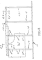
- FIG. 3 is a fragmentary side elevational view looking towards framing composed of an upper channel, a lower channel, a plurality of spaced apart, parallel studs extending between the two channels, and wallboard sheeting connected to the studs;
- FIG. 4 is a sectional view taken substantially along line 4 - 4 of FIG. 3;
- FIG. 5 is a sectional view taken substantially along line 5 - 5 of FIG. 3;
- FIG. 6 is a view like FIG. 4 but showing additional layers of wallboard sheeting
- FIG. 7 is a view like FIG. 6 and also showing additional layers of wallboard sheeting
- FIG. 8 is a pictorial view of the clip that is shown in FIGS. 1, 2, 5 and 7 ;
- FIG. 9 is a view like FIG. 8 but of a modified form of clip
- FIG. 10 is a view like FIGS. 8 and 9 but of another form of clip
- FIG. 11 is a view like FIGS. 8 - 10 but of yet another form of clip
- FIG. 12 is a view like FIGS. 8 - 11 but of a further form of clip
- FIG. 13 is a view like FIGS. 8 - 12 but of a yet another form of clip
- FIG. 14 is a view like FIGS. 8 - 13 but of yet another form of clip
- FIG. 15 is an end elevational view of the stud shown in FIG. 14;
- FIG. 16 is an end elevational view of the clip shown in FIG. 14;
- FIG. 17 is an end view of the clip shown by FIG. 14 when telescopically received within the stud shown by FIG. 14;
- FIG. 18 is a pictorial view of an upper end portion of a stud and another form of clip
- FIG. 19 is a view like FIG. 18 showing still another form of clip
- FIG. 20 is a side elevational view of a screw adapted to drill its way into metal, with it leading end spaced from two thicknesses of metal;
- FIG. 21 is an end view of the head end of the screw shown by FIG. 20;
- FIG. 22 is a view like FIG. 20 but showing the screw extended through both thicknesses of metal;
- FIG. 23 is an end view at the forward end of the screw shown by FIGS. 20 - 22 ;
- FIG. 24 is a view of a screw like the screw shown in FIGS. 20 and 22, shown spaced from two metal members, the nearest one of which has a preformed opening in it;
- FIG. 25 is a view similar to FIG. 24, but showing a screw that includes a shoulder adjacent the head, adapted to enter a slot and keep the head from clamping down on the metal member that includes the slot;
- FIG. 26 is a view like FIG. 25, but showing the screw installed
- FIG. 27 is a pictorial view of a clip in telescopic engagement with the upper portion of a stud, such view showing a longitudinal slot in the web of the stud that is contiguous the web of the clip;
- FIG. 28 is a view like FIG. 27, but showing the clip spaced endwise outwardly from the stud, and showing a screw fastener in a spaced relationship with the slot in the stud and an opening in the clip;
- FIG. 29 is a view like FIG. 27, but showing two longitudinal slots in the web of the stud;
- FIG. 30 is a view like FIG. 28, but showing two longitudinal slots in the web of the stud and two screw fasteners used for connecting the stud to the clip;
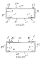
- FIG. 31 is an end view of a clip inside of a stud, such view showing the clip having relatively wide lips and showing broken lines where screw fasteners extend through the lips of the clip and the web of the stud;
- FIG. 32 is a view like FIG. 31, but showing the stud having relatively wide lips and including broken lines indicating where screw fasteners extend through the stud lips and the web of the clip;
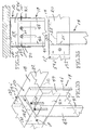
- FIG. 33 is a pictorial view of an embodiment of the invention in which the clip is positioned within the upper channel space on the outside of the web of the stud, such view showing slots in the web of the stud and screw fasteners extending through the slots and screwing into the web of the clip;
- FIG. 34 an elevational view looking towards the inside of the stud web and showing the heads of the screw fasteners
- FIG. 35 is a fragmentary view showing an upper end portion of a stud, a portion of the upper channel member and a clip in the channel member positioned next to the upper end portion stud, such view including a broken line showing the location of a screw fastener that extends through a slot in the stud web and screws into the web of the clip; and
- FIG. 36 is a view like FIG. 7, but showing an upper track that is formed by a pair of angle members, arranged with their upper legs or flanges projecting laterally outwardly from their vertical legs or flanges which form the track space between them.
- FIGS. 1 - 7 show wall framing comprising an upper sheet metal channel member 10 , a lower sheet metal channel member 12 and a plurality of studs 14 that are supported at their lower ends in the lower sheet metal channel 12 and at their upper ends project into a channel space 16 formed below an upper web 18 and between a pair of side flanges 20 , 22 that depend from the web 18 .
- the lower channel 12 includes a channel space 24 that is defined above a lower web 26 and between a pair of side flanges 28 , 30 that project upwardly from the lower web 26 .
- the upper flanges 20 , 22 include lower edges 32 , 34 .
- the lower flanges 28 , 30 include upper edges 34 , 36 .
- a plurality of sheet metal studs 14 are spaced apart along the channels 10 , 12 .
- the studs 14 are parallel to each other and are perpendicular to the channels 10 , 12 .
- each studs 14 preferably has a web 40 , front and rear (or first and second) flanges 42 , 44 and a pair of lips 46 , 48 .
- the flanges 42 , 44 are parallel to each other and are perpendicular to the web 40 .
- the lips 46 , 48 are in spaced, coplanar parallelism with and are perpendicular to the flanges 42 , 44 . They are also parallel to the web 40 .
- the front to rear dimension of the studs substantially equals the distance between the side flanges 28 , 30 of the lower channel member 12 .
- Web 40 and lips 46 , 48 extend perpendicular to the upper side flanges 20 , 22 and the lower side flanges 28 , 30 .
- Each stud 14 includes a lower butt end 50 and an upper butt end 52 .
- Butt end 50 preferably rests on the web 26 .
- Butt end 52 is spaced above the lower edges 32 , 34 a distance x and below the upper web 18 a distance y .
- the dimensions x , y are variable dimensions. This is because the framing permits relative vertical movement between the upper channel 10 and the rest of the wall structure that includes the studs 14 and the lower channel member 12 .
- FIG. 1 shows an at rest position. When the wall structure is in this position, the dimension x is smaller than the dimension y but is large enough to provide substantial lateral bracing between the upper end portions of the studs 14 and the side flanges 20 , 22 of the upper channel member 10 .
- each clip 54 is provided for each stud 12 .
- Each clip 54 has an upper portion that extends upwardly into the channel space 16 and a lower portion that extends downwardly into the upper end of its stud 14 .
- the upper portions of the clips 54 are connected to the upper channel members 10 whereas the lower portions of the clips 54 extend downwardly into the upper end portions of the studs 14 and make a relatively snug fit with the interior surfaces of the stud 14 .
- FIGS. 1 - 8 show a first embodiment of a clip 54 . It has an upper butt end 56 , a lower butt end 58 , a web 60 , a pair of flanges 62 , 64 and a pair of lips 66 , 68 .
- the cross sectional configuration of the clip 54 is like the cross sectional configuration of the studs 14 except that its dimensions are smaller so that its lower portion can snugly fit within the upper portion of the stud 14 .
- this form of clip 54 is within the upper end portion of a stud 14 , its flanges 62 , 64 are inwardly contiguous the flanges 42 , 44 of the stud 14 .
- Its web 60 is inwardly contiguous the web 40 of the stud 14 .
- Its lips 66 , 68 are inwardly contiguous the lips 46 , 48 of the stud 14 .
- each clip 54 is dimensioned such that it frictionally engages the inner surfaces of the upper end portions of its stud 14 .
- the outer surfaces of the stud flanges 62 , 64 are spaced inwardly from the side flanges 20 , 22 of the upper channel member 10 a distance substantially equal to the thickness of a stud flange 62 , 64 .
- Upper portions of the stud flanges 42 , 44 are sandwiched between lower portions of the side flanges 20 , 22 of the upper channel 10 and adjacent portions of the clip flanges 62 , 64 .
- screw fasteners are inserted at locations SF through the sidewalls 20 , 22 of the upper channel member 10 .
- the screw fasteners and screw into the clip flanges 62 , 64 at a location between the upper web 18 and the upper butt end 52 of the stud 14 .
- No fasteners are inserted through the upper side flanges 20 , 22 and the stud flanges 42 , 44 .
- the side flanges 20 , 22 of the upper flange 10 are drawn towards the clip flanges 62 , 64 . This increases the frictional forces acting between the stud flanges 46 , 48 , the clip flanges 62 , 64 and the side flanges 20 , 22 of the upper channel 10 .
- the distance x is always sufficiently long that contact is made between the stud flanges 42 , 44 and the side flanges 20 , 22 of the upper channel 10 . This allows the use of a short clip 54 . Also, the clip 54 can have a cross sectional dimension that is smaller than the cross sectional dimension of the stud 14 .
- the upper channel members 10 are connected to an upper concrete structure 70 . This is usually done by inserting screw fasteners through the web 18 at a plurality of longitudinally and laterally spaced apart locations. In FIG. 5, two screw fastener locations are designated SF.
- the lower channel member 12 is connected to a lower concrete structure (not shown). This is typically done by the use of laterally and longitudinally spaced apart screw fasteners (not shown) that extend between the lower web 24 and the lower concrete structure.
- the upper and lower concrete structures are fixed relatively to each other most of the time. However, during earthquakes, and other times as well, there will be some vertical movement of the two concrete structures relative to each other. At times they may move relatively toward each other and at other times they may move relatively apart. As previously described, the studs 14 are connected to the lower channel member 12 and thus are in that manner connected to the lower concrete structure. However, they are not connected to either the upper channel member 10 or the upper concrete structure 70 . The upper channel member 10 is connected to the upper concrete structure and thus can and will move with the upper concrete structure whenever it moves.
- the framing is covered (usually on both sides) by wallboard sheeting WS or some other form of sheeting.
- the sheeting comes in sheets measuring four feet by eight feet, or four feet by ten feet or four feet by twelve feet, for example. The thickness varies, for example, from one-half inch to five eights of an inch to three-quarters of an inch.
- the wallboard sheeting WS is secured to the studs 14 , preferably by screw fasteners SF.
- “SF” is used to designate both the screw fasteners and openings which receive the screw fasteners.
- the screw fasteners SF extend through the wallboard sheeting WS and screw into the flanges 42 , 44 of the studs 14 .
- FIGS. 4 and 5 show a single thickness of wallboard sheeting WS.
- the sheeting may, for example, be five eights (5 ⁇ 8′′) GWB gypsum wallboard.
- a single thickness of wallboard sheeting WS (FIGS. 4 and 5) provides what is referred to as a one-hour wall system. This means that the wall will prevent fire from moving through it for about one hour.
- FIGS. 6 and 7 show two thicknesses of wallboard sheeting WS. This provides a two-hour wall system. That is, the wall will prevent fire from passing through it for about two hours.
- the upper edges 76 , 78 are spaced below the lower edges 32 , 34 of the upper channel member 10 .
- wallboard strips 80 are provided immediately outwardly of the side flanges 20 , 22 of the upper channel member 10 .
- Wider wallboard strips 82 are provided outwardly of the wallboard strips 80 .
- Screw fasteners are used to secure the wallboard strips 80 , 82 to the side flanges 20 , 22 of the upper channel member.
- the wider strips 82 extend downwardly and overlap edge portions of the wallboard sheeting WS.
- the wallboard sheeting WS is secured to the studs 10 and at its lower edge may be secured to the side flanges 28 , 30 of the lower channel member 12 .
- the studs 10 are connected to the side flanges 28 , 30 of the lower channel members 12 and the sheeting is connected to the studs 14 .
- This assembly by itself effectively unites the wallboard sheeting WS, the studs 14 and the lower channel members 12 .
- FIGS. 4 - 7 a vertical space exists between the upper edges 76 , 78 of the wallboard sheeting WS, WS′. This allows the upper edges 76 , 78 to move relatively upwardly into this space during relative upward movement of the channel members 10 , 12 and the concrete structures to which they are connected.
- the wallboard sheeting WS, WS′ is connected to the studs 14 but is not connected to the clips 54 .
- the clips 54 have a substantially rigid configuration. When the lower portion of a clip is telescopically received in the upper portion of its stud 14 , the telescopic connection that is created resists most bending. The connection is reinforced by the cross sectional constructions of the stud 14 and the clips 54 .
- FIGS. 9 and 10 disclose telescopic connections between the clips and the studs 14 that are stiffened and further strengthened by additional structure.
- the clips shown by FIGS. 9 and 10 have what may be referred to as a “box” shape. They include a lipped channel and a panel that is secured to the lips of the channel by either screws or weld beads.
- Clips 54 a , 54 b each comprise a web 90 , first and second flanges 92 , 94 that are connected to the web 90 and extend perpendicular from it, and lips 96 , 98 .
- the lips 96 , 98 are connected to the flanges 92 , 94 and extend perpendicular to them, and parallel to the web 90 .
- Lips 96 , 98 are in coplanar parallelism.
- Clip 54 a includes a panel 100 that is fastened by screw fasteners SF to the lips 96 , 98 .
- the panel 102 is connected to the lips 96 by welds W.
- the “box” shape of clips 54 a , 54 b provides a more rigid dowel than the lipped channel shown by FIG. 8.
- These clips 54 a , 54 b are particularly suited for use in exterior wall structures that are subjected to large side loads (e.g. high velocity wind loads).
- FIG. 11 shows providing the lips of the clip with longitudinal slots that are adapted to receive shank portions of screw fasteners that extend through openings in the stud web and then extend through the slots.
- clip 54 c includes a web 104 , flanges 106 , 108 connected to the web 104 and lips 110 , 112 connected to the flanges 106 , 108 .
- the flanges 106 , 108 are parallel to each other and are perpendicular to the web 104 and the lips 110 , 112 .
- the lips 110 , 112 may be wider than the lips 66 , 68 in the clip 54 shown by FIG. 8.
- the lips 110 , 112 can be provided with longitudinal slots 114 .
- the slots 114 receive the shank portions of screw fasteners that are screwed into the on the stud web 14 .
- vertical movement of the clip 54 c relative to the stud 14 is limited by the length of the slots 114 .
- FIG. 12 discloses providing elongated slots in the web of the clip 54 d .
- Clip 54 d comprises a web 16 , a pair of flanges 118 , 120 and a pair of lips 122 , 124 .
- Web 116 is parallel to lips 122 , 124 and is perpendicular to flanges 118 , 120 .
- At least one (but preferably two) slot 126 is formed in the web 116 .
- Slot(s) 126 receive shank portions of screw fasteners used to secure the clip 54 d to a stud 14 .
- the relative movement between the clip 54 d and the stud 14 is limited by the length of the slot(s) 126 .
- FIG. 13 shows a simpler clip 54 e comprising a web 128 and two flanges 130 , 132 .
- This clip 54 e is not as rigid as the other clips and should only be used in internal wall systems that experience relatively low side loads.
- Clip 54 e is telescopically received within the upper end portion of a stud 14 , in the manner shown by FIG. 1. The only difference is that in the system that includes a clip 54 e , the free edges of the flanges 130 , 134 extend substantially to the inner surfaces of the lips 46 , 48 on the stud 14 .
- FIGS. 14 - 17 show providing the clip 54 f with longitudinal channels 134 outwardly of its lips 136 , 138 .
- the stud lips 46 , 48 are received in the channels 134 .
- This fit strengthens the telescopic connection.
- the clip 54 f includes a web 140 flanges 142 , 144 and the channels 134 .
- the channels 134 are formed by and between inner lips 146 , 148 and outer lips 150 , 152 .
- the lips 146 , 148 and 150 , 154 are substantially parallel to each other and the web 140 and are substantially perpendicular to the flanges 144 , 142 .
- 17 is a cross sectional view through the stud 14 and the clip 54 f . This view clearly shows the stud lips 46 , 48 received within the channels 134 . This provides an interlock between the two members and results in a stiffened connection, capable of withstanding substantial bending force at the connection.
- FIG. 18 shows a clip 150 that includes an upper portion 152 and a lower portion 154 that is telescopically received in the stud 14 .
- Upper portion 152 is a flat panel that is adapted to extend horizontally. It is connected to a vertical panel 156 that has a width substantially equal to the distance between the stud flanges 42 , 44 . At its lower end, panel 156 connects to a panel 158 .
- Another panel 160 is connected to panel 158 .
- Panel 152 is perpendicular to panels 156 and 160 . It is parallel to panel 158 .
- Panels 156 and 160 have a common width that is equal to the width of panel 156 .
- Panel 156 is substantially the length of the clips that have already been described e.g. clip 54 in FIGS. 1 and 2.
- the panel 152 is moved upwardly against the upper web 18 of the upper channel member 10 .
- screw fasteners are inserted through the openings designated as SF.
- the screws are inserted upwardly from below panel 152 , through the openings SF. They are then screwed into the upper web 18 . When the screws are tightened, they draw the panel 152 into tight engagement with the web 18 .
- the lower portion of the clip 152 composed of panels 154 , 156 , and 160 are snuggly received within the stud 14 .
- the shape of the panels 154 , 158 , 160 , and their snug fit within the stud 14 substantially restrains the stud 14 and clip 150 from movement relative to each other in all directions except for the vertical direction.
- the telescopic connection between the clip 150 and the stud 14 permits relative vertical movement between the two members 150 , 14 .
- FIG. 19 shows a modified clip 162 .
- the panel 160 ′ extends upwardly from panel 158 on its side of panel 158 in the same manner that panel 156 extends up from the opposite side of panel 158 .
- the upper end of panel 160 ′ is connected to another panel 164 .
- Panels 152 , 164 are in coplanar parallelism. Both of these panels are connected to the upper web 18 of the upper channel member 10 by screw fasteners SF which are inserted upwardly through the openings SF.
- the panels 156 , 158 , 1601 form the lower portion of the clip 150 that is telescopically received in the upper portion of the stud 14 .
- the structure formed by panels 156 , 158 , 160 ′ is snuggly received within the stud 14 . It substantially restrains relative movement between clip 150 and stud 14 in all directions except the vertical direction. Relative movement is possible in the vertical direction because of the telescopic connection between the two members.
- FIGS. 27 - 30 show providing at least one longitudinal slot in the web of the stud. Screw fasteners SF extend through the slots and then screw into the webs of the clips.
- FIGS. 27 - 30 the same reference numerals will be used that are used in FIGS. 1 - 2 except for where there is a difference.
- the difference is the existence of a single slot 180 in the stud web 40 .
- the difference is the presence of two slots 180 in the stud web 40 .
- a screw fastener 182 extends first through the slot 180 and then screws into the web 60 of clip 54 at location 184 (FIG. 28).
- FIGS. 28 shows providing at least one longitudinal slot in the web of the stud. Screw fasteners SF extend through the slots and then screw into the webs of the clips.
- FIGS. 27 - 30 the same reference numerals will be used that are used in FIGS. 1 - 2 except for where there is a difference.
- the difference is the existence of a single slot 180 in the
- two screw fasteners 182 extend through the two slots 180 and then screw into the web 60 of the clip 54 at location 186 .
- relative vertical movement can occur between the clip 54 and the stud 14 within limits set by the ends of the slots 180 .
- FIGS. 20 - 24 show a screw fastener 190 (also SF) that includes a slotted head 192 adapted to receive a tip of a screwdriver in the slot 194 (FIG. 21).
- a threaded shank 196 is connected. No the head 192 and extends away from it on the side of the head 192 opposite the slots 194 .
- the shank 196 includes a tip 198 that is in the nature of a drill bit tip. It is adapted to drill a hole through one or more sheet metal members in response to rotation of the screw fastener 190 .
- FIG. 20 shows the screw fastener 190 with its tip 198 spaced from a pair of sheet metal members.
- these members may be side flange 20 of the upper channel member 10 and flange 42 of the stud 14 .
- a power driver is used to rotate the screw fastener 190
- the tip 190 drills a hole first through member 20 and then through member 42 .
- the threaded portion of the shank 196 moves the screw fastener 198 through the openings until its head 192 is against member 20 . This connects the two members 20 , 42 together with the head 192 bearing tight against the member 20 , as shown by FIG. 22.
- FIG. 24 shows the screw fastener tip 198 spaced from a pre-drilled opening 200 in the member 20 .
- the tip 198 only has to drill through the metal member 42 .
- the provision of pre-drilled holes 200 in one of two members that are to be connected together substantially reduces the installation time of the screw fasteners. Again, this is because the tip 198 does not have to drill its way through two members. It only has to drill its way through one member.
- the screw fastener is used to form an opening in a stud panel at a location immediately outwardly from a slot 114 , 26 .
- the lips 110 , 112 are preferably inwardly contiguous the stud web 40 .
- the screw fastener drills a hole for itself through the web 40 and then it moves through the slots 114 .
- the screw fastener 190 can be driven until its head 192 is tight against the web 40 .
- Each slot 114 is wider than the threaded shank of the screw fastener 190 .
- the threads of the screw fastener 190 do not engage the lips 110 , 112 of the clip 54 c .
- the clip 54 c is able to move up and down freely relative to the stud 14 between the two ends of the slots 114 .
- the web 116 is inwardly contiguous the stud web 40 .
- the screw fasteners 190 bite into the web 40 but not the web 116 .
- the threaded shanks of the screw fasteners 190 pass through the slots 196 , resulting in clip 54 d being freely movable vertically relative to the stud 14 .
- FIGS. 25 and 26 show a modified screw fastener 204 that is for use with the embodiments shown by FIGS. 27 - 30 .
- Screw fastener 204 includes a threaded shank 206 , a drill tip 208 and a head 210 . It also includes a spacer member 212 between the head 210 and the threaded shank 206 .
- the diameter 214 of member 212 is smaller than the width dimension of the slot 180 .
- the axial dimension 216 of member 212 is greater than the thickness of web 40 .
- the screw fastener is rotated and moved axially through the slot 180 and against the web 60 , causing tip 208 to drill its way through the web 60 .
- the threaded shank 206 engages the edges of the opening and pulls the threaded fastener 204 through web 60 until member 212 is within the slot 180 .
- the surface 218 is moved tight against web 60 where it surrounds the opening. This is shown by FIG. 26.
- FIG. 26 also shows that the spacer member 212 is narrower that the slot and when the surface 218 is against web 60 , the head 210 is spaces axially from the web 40 .
- the screw fastener 204 can be screwed in as far as it will go without web 40 being clamped between head 210 and web 60 .
- the clip 54 is free to move longitudinally relative to the stud 14 , within the limits of the end of the slots 180 .
- the clips may be united with the studs in the factory or the clips and studs may be sent to the job site unassembled and assembled there.
- the lower end portion of each stud is inserted into the channel space of the lower channel member 12 .
- the stud 14 is put into a vertical position with its lower butt end resting on the lower web 24 of the lower channel member 12 .
- its upper butt end 52 is spaced above the lower edges 32 , 34 of the side flanges 20 , 22 of the upper channel member 10 and below the upper web 18 of the upper channel member 10 .
- the upper portions of the web side flanges 42 , 44 are sandwiched between the side flanges 20 , 22 of the upper channel member 10 and contiguous portions of the clip. In most of the embodiments, this portion of the clip is a side flange of the clip. See flanges 18 , 20 in FIG. 12, for example.
- the upper end portion of the clip is connected to the upper channel member.
- a screw fastener SF is inserted through the side flanges 20 , 22 of the upper channel member 10 and then through the adjacent side flanges of the clip.
- the upper portion or portions of each clip is secured to the web 18 of the upper channel member 10 , by the use of screw fasteners.
- the wallboard sheeting WS is connected to the studs 14 but not in the regions of the clips or the side flanges 20 , 22 of the upper channel member.
- the lower channel member 12 is typically secured to a lower concrete structure, e.g. a concrete slab in the building.
- the upper channel member 10 is in a similar fashion secured to an upper concrete structure, e.g. another concrete slab that is positioned above the first slab.
- the connection of the upper channel member 10 to the upper concrete structure will result in the upper concrete structure and the channel member 10 moving together if there is any reason for either one of them to move.
- the same is true with respect to the lower concrete structure and the lower channel member 12 .
- buildings settle and their floor structures move relative to each other. Also, during an earthquake, there can be substantial movement of the concrete structures relative to each other.
- the use of the clips together with the shortened studs provides a telescopic connection between the clip and the stud that will accommodate the movement that will occur under most circumstances.
- the stud is firmly connected to both the upper channel member 10 and the lower channel member 12 for movement normal to the plain of the wall and parallel to the plain of the wall.
- slots such as shown by FIGS. 11,12 and 27 - 30 does not present a problem because these slots are used in the connection of the clip to the stud.
- This connection does not have to be done through wallboard sheeting. It is done at a time when the location of the slot is clearly visible and care can be taken to see that the screw fastener is properly positioned in the slot.
- the workman see this and can remove the screw fastener and replace it with a properly located screw fastener before sheeting is place on the wall.
- jigs can be developed that will make the drilling operation exact and substantially automatic.
- FIG. 31 is an end view of a clip 54 c where it is telescopically received within a stud 14 .
- This system can be compared with the system shown by FIGS. 29 and 30. The difference is, in this system the clip 54 c is turned around before it is inserted into the stud 14 . Its lips 110 , 112 are contiguous the stud web 40 . Screw fasteners are provided at SF. These screw fasteners can either screw into one of the metal members and then extend through a slot in the other, or they can first extend through a slot in one member and then screw into the other member. For example, the screw fasteners SF may screw through the stud web 40 and then extend through the slots 114 in the lips 110 , 112 of the clip 54 c.
- the system shown by FIG. 32 comprises a stud 14 ′ having relatively wide lips 46 ′, 48 ′.
- Either the lips 46 ′, 48 ′ include slots or the slots are formed in the clip web 60 .
- the screw fasteners SF either extend through a slot in a first member and then screw into the second member, or screw into the first member and then extend through a slot in the second member.
- a screw fastener like screw fastener 204 (FIGS. 25 and 26) is used.
- a screw fastener like the screw fastener 196 (FIGS. 20 - 24 ) is used.
- the screw fastener may first screw into a first metal member and then extend through a slot in the second metal member. Or, it may first extend through a slot in a first metal member and then screw into the second metal member. In each case, the appropriate screw fastener 196 , 204 is used.
- FIGS. 33 - 35 show another embodiment of the invention.
- a clip is used that is positioned within the channel space 16 adjacent to but outside of the upper end portion of the stud 14 .
- the clip may be like any of the clips that have been illustrated and described.
- a clip 54 e ′ is used.
- the difference between clip 54 e ′ and clip 54 e is that in clip 54 e ′ the distance between the outer sides of the flanges 130 , 132 is substantially equal to the distance between the inner sides of the flanges 20 , 22 of the upper channel member 10 .
- screw fasteners SF are used to secure the flanges 20 , 22 to the flanges 132 , 130 , respectively. This is done when the upper butt end of the clip 54 e ′ is up against the lower surface of the web 18 . This abutting relationship of the end of the clip 54 e ′ and the use of the two screw fasteners SF keeps the clip 54 e ′ from rotating in position inside the channel space 16 .
- slots are either provided in the stud web 40 or in the clip web 128 . Screw fasteners are used at the locations of these slots to secure the upper end portion of the stud 14 to the clip 54 e ′.
- the screw fasteners may extend either first through the slots and then into the other web member. Or they may first screw through a web member and then extend through the slots in the other web member.
- a screw fastener like screw fastener 196 is used when the screw fastener is first screwed into a web.
- a fastener like fastener 204 is used when the screw fastener first extends through a slot and then screws into the adjacent web.
- the screw fasteners may be nut and bolt assemblies rather than screw members.
- bolts may be provided that have shoulder portions adjacent the bolt heads that are adapted to extend into slots formed in one of the metal members.
- the shoulder has an end portion that bears against the metal member that does not include the slot.
- the shoulder is long enough so that when the end of the shoulder is against the metal, the head of the fastener is spaced away from the slotted member a small amount, so that the fastener head will not clamp the slotted member to the other member when it is tightened.
- FIG. 36 is similar to FIG. 7 except that the upper track member 10 that is in FIG. 7 has in FIG. 36 been replaced by a pair of angle iron members 200 , 202 .
- Angle iron member 200 includes a horizontal flange 204 and a vertical flange 206 .
- Channel member 202 includes a horizontal upper flange 208 and a vertical flange 210 .
- Flange 206 makes a right angle connection with flange 204 .
- flange 210 makes a right angle connection with flange 208 .
- Flanges 200 , 202 are secured to the overhead structure 212 by suitable fasteners 214 .
- the vertical flanges 206 , 210 are spaced apart substantially the same distance as the side flanges 20 , 22 in the previously described upper channel member 10 .
- the side flanges 20 , 22 form a channel or “track” space between them.
- the vertical flanges 206 , 210 form a channel or “track” space between them.
- the clip 54 is telescopically received in the upper end portion of the stud 14 . Screw fasteners 216 are used to connect the side flanges 206 , 210 to the upper portion of the clip 54 .
- the angle iron members 200 , 206 may be separately attached to the structure 212 , and then the clips 54 may be inserted and connected to the side flanges 206 , 210 . Or, a plurality of the clips may be connected to the side flanges 206 , 210 of the angle iron members 200 , 202 , to form an assembly composed of the angle iron members 200 , 202 and the clips 54 . Then, this assembly can be lifted up and set in place and then secured to the structure 212 by the fasteners 214 that first pass through the horizontal legs or flanges 204 , 208 of the angle iron members 200 , 202 .
- each of the previously described clips, and also later developed clips can be used with the angle iron members 200 , 202 .
- the studs, the channels, the angle iron members and the clips are all formed from between twelve and twenty-six gauge sheet metal. Bend radiuses are formed between the flanges and the webs of the channel members, between the lips and the flanges of the lip channel members and between the two legs or flanges of the angle iron members.
- the clips measure about four inches in length.
- the side flanges of the channel members 10 , 12 and the vertical flanges of the angle iron members 200 , 202 are about 2.5 inches in the vertical direction.
- the static distance between the lower edges of the side flanges 20 , 22 and the upper butt ends of the studs 14 is preferably about one and one-half inches.
- the slots may be about three-sixteenths inches in width and about two inches in length.
Abstract
A downwardly opening upper channel member (10) is positioned above an upwardly opening lower channel member (12). A lower end portion of a stud (14) is received in the lower channel member (12). A clip (54) is received in an upper end portion of the stud bracket (10). The clip (54) has an upper portion that is connected to the upper channel member (10). It also has a lower portion that extends downwardly into an upper end portion of its stud (14). The upper channel member (10) has opposite side flanges (20, 22) that include lower edges (32, 34) the stud (14) has an upper butt end that is positioned above the lower edge (32, 34) is below an upper web portion (18) of the upper channel member (10). The upper portion of the clip (54) is connected to the upper channel member (10). The clip (54) is free to move vertically with respect to the stud (14). In a wall construction, wallboard sheeting WS is connected to the stud (14) and the lower channel member (12) but not to the upper channel member (10). As a result, relative vertical movement is permitted between the upper channel member (10) and the rest of the wall which includes the stud (14), the lower channel member (12) and the wallboard sheeting WS.
Description
- This invention relates to wall structures composed of metal framing and wallboard sheeting connected to the framing. More particularly, it relates to a simple way of providing for relative movement between an upper channel member, or header, and the rest of the wall, in response to wall movement such as may occur during an earthquake, for example.
- It is well known to use metal framing in building wall construction. Commonly, the framing comprises a downwardly opening upper channel, or header, an upwardly opening upper channel, or footer, and vertical studs extending between the channels and having end portions that are within the channels. An advantage of using metal framing members is that they provide a strong frame structure that can be configured to accommodate for movement of the buildings such as occurs during an earthquake, without resulting in damage to the wall of which the framing is a part.
- Typically, the upper channel member is secured to an upper concrete structure and the lower channel member is secured to a lower concrete structure. During an earthquake, and at other times as well, there is relative movement between the two concrete structures. It is necessary that the framing that extends between the concrete structures be able to accommodate the relative movement without damage to the framing and the wall of which it is a part. Relative movement between the two concrete structures can be caused by earthquakes, roof loads, expansion and contraction, loading and unloading upper floors in multi-story buildings, settling, and wind loads, for example.
- U.S. Pat. No. 5,127,203, granted Jul. 7, 1992, to Robert F. Paquette, and U.S. Pat. No. 5,127,760, granted Jul. 7, 1992, to Todd A. Brady, each discloses the use of vertical slots in the flanges of overhead channels, for receiving screws that are used to secure upper end portions of the studs to the overhead channels. The overhead channels are provided with a plurality of slots so that a stud can be selectively positioned at a number of locations along the channel length. Screw fasteners are inserted through the slots and are then screwed into the upper end portions of the studs. In response to movement of the building, the upper channel member is movable relative to the studs and the wallboard that is connected to the studs. A problem with this use of slots is that constructing the upper channel members to include the slots is an added expense. Also, the slots weaken the metal. It often becomes necessary to use a heavier gauge metal to compensate for the loss in strength caused by use of the slots. This adds addition expense as heavier gauge metal is more expensive than lighter gauge metal.
- U.S. Pat. No. 5,685,121, granted Nov. 11, 1997, to Frank DeFrancesco and Joseph Domenick Palumbo, discloses a use of a two-section stud. The upper end of the upper section is an upper channel and the lower end of the lower section is in a lower channel. The upper section is telescopically received within the lower section and includes a pair of slots that extend throughout a substantial portion of the length of the upper section. A problem with this construction is that the location of the slots cannot be determined for sure and the fasteners used may end up securing the lower section to the upper section. The installers must place the wallboard sheeting on the studs and then drill through the sheeting and the outer flange of the lower section of the stud at locations which are outwardly of the slots in the upper sections of the studs. If a screw fastener is not in alignment with a slot, it will screw into the metal bordering the slot. As a result, the upper and lower sections of the stud will be screwed together and relative movement between the two will be prevented. In such an event, the two sections of the stud are not free to move relative to each other in response to seismic or other forces to which the wall may be subjected. Also, it is difficult and expensive to make the long slots, to provide the upper section with a flared upper end, and to provide the upper section with the longitudinal V-shaped flanges that are a part of the system. Also, considerable more steel is needed in a wall that uses the two-section stud of this system.
- There is a need for a wall construction that permits movement of the upper channel member relative to the rest of the wall in a positive manner without adding substantial manufacturing and/or installation costs. A principal object of the present invention is to provide such a wall structure.
- A wall structure to which the present invention relates comprises a downwardly opening upper channel member that includes an upper web and a pair of spaced apart side flanges depending from the upper web to the lower edges. The upper web and the side flanges form a channel space below the upper web and between the side flanges. The wall structure also includes a plurality of vertically extending studs that are horizontally spaced apart. Each stud includes an upper end portion and an upper butt end. The upper end portions of the studs are received in the channel space, with the butt ends of the studs positioned above the lower edges of the side flanges of the upper channel member. According to the invention, each stud is provided with a clip. Each clip comprises an upper portion that is received in and secured to the upper channel member, and a lower portion that extends downwardly from the upper portion into the upper end portion of its stud. The lower end portion of each clip is snuggly received within, and preferably makes frictional engagement with, the upper end portion of its stud. The studs are moveable up and down in the channel space relative to both the clips and the upper channel member when subjected to a force that overcomes the frictional forces.
- In preferred form, each stud comprises a web extending perpendicular to the side flanges of the upper channel and front and rear flanges connected to the web. The front and rear flanges extend parallel to the side flanges of the upper channel. The studs include lips that are connected to the flanges and extend inwardly towards each other, in coplanar parallelism. The lips are in spaced parallelism with the web. Also in preferred form, the clip has front and rear boundaries that are contiguous stud flanges.
- In one embodiment, each clip comprises a web that is inwardly contiguous the web of its stud and front and rear flanges connected to the web of the clip that are inwardly contiguous front and rear flanges of its stud. The clip and stud combination of this invention requires much less steel than the two-section stud disclosed by U.S. Pat. No. 5,685,121. More specifically, that system requires approximately fifty percent more steel than the clip and stud system provided by the present invention.
- According to an aspect of the invention, screw fasteners extend through the side flanges of the upper channel and through the front and rear flanges of the upper portions of the clips. Upper portions of the front and rear flanges of each stud are sandwiched between the side flanges of the upper channel and lower portions of the front and rear flanges of the clip.
- It is an object of the present invention to provide framing for internal walls, framing for external walls and framing that can be used in both internal and external walls. External building walls generally have larger side loads (e.g. wind loads) on them than interior walls.
- According to an embodiment of the invention, the web of the clip, or the web of the stud includes at least one vertical slot. A screw fastener extends through the other web and through the slot and connects the clip to the stud. The slot is sized and positioned to allow up and down movement of the clip relative to the stud and the upper channel member.
- In another embodiment of the invention, the clips included lips that are inwardly contiguous the lips on their stud. A vertical slot is provided in at least one lip on either the clip or the stud and for each slot a screw fastener extends through the other lip and the slot and connects the clip to the stud. The slot is of a length and is positioned to allow vertical movement of the clips relative to the studs and the upper channel member.
- In still another embodiment, the clips are telescopically received within the studs and the clips include longitudinal channels in which the lips on the studs are received.
- According to a further aspect of the invention, clips are provided that include at least one upper portion that extends perpendicular to the stud and parallel to the upper web of the upper channel member. At least one screw fastener connects said upper portion of the clip to the upper web of the upper channel member. Each clip may include two upper portions which extend perpendicular to its stud and parallel to the upper web of the upper channel member. In such case one of the upper portions extends along the upper channel member in a first direction from the clip. The other upper portion extends along the upper channel member in the opposite direction from the clip. At least one fastener is used to connect at least one of said upper portion of each clip to the upper web of the upper channel member. In one embodiment, each upper portion of the clip is connected to the upper web of the upper channel member by at least one fastener.
- In a typical wall, the framing includes an upwardly opening lower channel member having a lower web and a pair of spaced apart flanges extending upwardly from the lower web to upper edges. The lower web and side flanges form a channel space above the lower web and between the side flanges. The studs include lower end portions that are received in the channel space. The studs have lower butt ends that contact the lower web.
- A feature of the invention is that vertical studs are supported at their lower ends in an upwardly opening lower channel member and the studs include upper end portions that project upwardly into an upper channel space formed in a downwardly opening upper channel member. The upper end portions of the studs are contiguous side flanges of the upper channel member and include butt ends that are spaced downwardly from an upper web portion of the upper channel member. A clip is provided for each stud. Each clip includes an upper portion that is connected to an upper channel member and a lower portion that extends downwardly into its stud. This construction allows the upper end portions of the studs to be braced longitudinally and laterally of the upper channel member while at the same time permits the studs and the rest of the wall below the upper channel member to move up and down relative to the upper channel member, and also allows the upper channel member to move up and down relative to the studs and the rest of the wall.
- According to an aspect of the invention, the upper end portions of the clips can be adapted to be connected to the web of the upper channel member or can be adapted to be connected to the side flanges of the upper channel member.
- According to a further aspect of the invention, fasteners that secure sheeting to the studs enter into the studs but not into either the clips or the upper channel member.
- The present invention includes providing a wall framing system in which there are yieldable connections between the studs and an overhead channel member. There is telescopic engagement of the studs with clips that are connected to the overhead channel member. This connection transfers longitudinal and lateral wall forces between the studs and the clips. The clips then transfer these forces to the upper channel member. In the connection, front and rear wall parts of the upper portions of the studs are sandwiched between lower end portions of the clips and side flange portions of the upper channel member.
- The upper channel member forms what is sometimes referred to as an upper track. The essential parts of the upper track are the side panels that form a channel or track space between them. It is within the scope of the present invention to employ an upper track that is composed of two angle iron members. Each angle iron member includes a horizontal upper flange that is used to secure it to the overhead structure and a vertical flange that provides the side flange of the track.
- Other objects, advantages and features of the invention will become apparent from the detailed description that is set forth below, from the drawings and from the claims.
- Like reference numerals are used to designate like parts throughout the several views of the drawing, and:
- FIG. 1 is a fragmentary pictorial view looking towards the assembly of an upper channel member, a lower channel member, a stud having an upper end portion, and a clip in said upper end portion, said clip being shown connected to the upper channel member, said view being taken from above, with the mid portion of the stud being broken away for purposes of indicating indeterminate length;
- FIG. 2 is an exploded pictorial view of the framing assembly shown by FIG. 1, such view including a fragmentary portion of some sheeting that is connected to the stud;
- FIG. 3 is a fragmentary side elevational view looking towards framing composed of an upper channel, a lower channel, a plurality of spaced apart, parallel studs extending between the two channels, and wallboard sheeting connected to the studs;
- FIG. 4 is a sectional view taken substantially along line 4-4 of FIG. 3;
- FIG. 5 is a sectional view taken substantially along line 5-5 of FIG. 3;
- FIG. 6 is a view like FIG. 4 but showing additional layers of wallboard sheeting;
- FIG. 7 is a view like FIG. 6 and also showing additional layers of wallboard sheeting;
- FIG. 8 is a pictorial view of the clip that is shown in FIGS. 1, 2, 5 and 7;
- FIG. 9 is a view like FIG. 8 but of a modified form of clip;
- FIG. 10 is a view like FIGS. 8 and 9 but of another form of clip;
- FIG. 11 is a view like FIGS. 8-10 but of yet another form of clip;
- FIG. 12 is a view like FIGS. 8-11 but of a further form of clip;
- FIG. 13 is a view like FIGS. 8-12 but of a yet another form of clip;
- FIG. 14 is a view like FIGS. 8-13 but of yet another form of clip;
- FIG. 15 is an end elevational view of the stud shown in FIG. 14;
- FIG. 16 is an end elevational view of the clip shown in FIG. 14;
- FIG. 17 is an end view of the clip shown by FIG. 14 when telescopically received within the stud shown by FIG. 14;
- FIG. 18 is a pictorial view of an upper end portion of a stud and another form of clip;
- FIG. 19 is a view like FIG. 18 showing still another form of clip;
- FIG. 20 is a side elevational view of a screw adapted to drill its way into metal, with it leading end spaced from two thicknesses of metal;
- FIG. 21 is an end view of the head end of the screw shown by FIG. 20;
- FIG. 22 is a view like FIG. 20 but showing the screw extended through both thicknesses of metal;
- FIG. 23 is an end view at the forward end of the screw shown by FIGS. 20-22;
- FIG. 24 is a view of a screw like the screw shown in FIGS. 20 and 22, shown spaced from two metal members, the nearest one of which has a preformed opening in it;
- FIG. 25 is a view similar to FIG. 24, but showing a screw that includes a shoulder adjacent the head, adapted to enter a slot and keep the head from clamping down on the metal member that includes the slot;
- FIG. 26 is a view like FIG. 25, but showing the screw installed;
- FIG. 27 is a pictorial view of a clip in telescopic engagement with the upper portion of a stud, such view showing a longitudinal slot in the web of the stud that is contiguous the web of the clip;
- FIG. 28 is a view like FIG. 27, but showing the clip spaced endwise outwardly from the stud, and showing a screw fastener in a spaced relationship with the slot in the stud and an opening in the clip;
- FIG. 29 is a view like FIG. 27, but showing two longitudinal slots in the web of the stud;
- FIG. 30 is a view like FIG. 28, but showing two longitudinal slots in the web of the stud and two screw fasteners used for connecting the stud to the clip;
- FIG. 31 is an end view of a clip inside of a stud, such view showing the clip having relatively wide lips and showing broken lines where screw fasteners extend through the lips of the clip and the web of the stud;
- FIG. 32 is a view like FIG. 31, but showing the stud having relatively wide lips and including broken lines indicating where screw fasteners extend through the stud lips and the web of the clip;
- FIG. 33 is a pictorial view of an embodiment of the invention in which the clip is positioned within the upper channel space on the outside of the web of the stud, such view showing slots in the web of the stud and screw fasteners extending through the slots and screwing into the web of the clip;
- FIG. 34 an elevational view looking towards the inside of the stud web and showing the heads of the screw fasteners;
- FIG. 35 is a fragmentary view showing an upper end portion of a stud, a portion of the upper channel member and a clip in the channel member positioned next to the upper end portion stud, such view including a broken line showing the location of a screw fastener that extends through a slot in the stud web and screws into the web of the clip; and
- FIG. 36 is a view like FIG. 7, but showing an upper track that is formed by a pair of angle members, arranged with their upper legs or flanges projecting laterally outwardly from their vertical legs or flanges which form the track space between them.
- FIGS. 1-7 show wall framing comprising an upper sheet
metal channel member 10, a lower sheetmetal channel member 12 and a plurality ofstuds 14 that are supported at their lower ends in the lowersheet metal channel 12 and at their upper ends project into achannel space 16 formed below anupper web 18 and between a pair ofside flanges web 18. Thelower channel 12 includes achannel space 24 that is defined above alower web 26 and between a pair ofside flanges lower web 26. Theupper flanges lower edges 32, 34. Thelower flanges upper edges sheet metal studs 14 are spaced apart along thechannels studs 14 are parallel to each other and are perpendicular to thechannels - Referring to FIGS. 1 and 2, in particular, each
studs 14 preferably has aweb 40, front and rear (or first and second) flanges 42, 44 and a pair oflips flanges web 40. Thelips flanges web 40. The front to rear dimension of the studs substantially equals the distance between theside flanges lower channel member 12.Web 40 andlips upper side flanges lower side flanges - Each
stud 14 includes alower butt end 50 and anupper butt end 52.Butt end 50 preferably rests on theweb 26.Butt end 52 is spaced above the lower edges 32, 34 a distance x and below the upper web 18 a distance y. As will hereinafter be explained, the dimensions x, y are variable dimensions. This is because the framing permits relative vertical movement between theupper channel 10 and the rest of the wall structure that includes thestuds 14 and thelower channel member 12. FIG. 1 shows an at rest position. When the wall structure is in this position, the dimension x is smaller than the dimension y but is large enough to provide substantial lateral bracing between the upper end portions of thestuds 14 and theside flanges upper channel member 10. - According to the invention, a
separate clip 54 is provided for eachstud 12. Eachclip 54 has an upper portion that extends upwardly into thechannel space 16 and a lower portion that extends downwardly into the upper end of itsstud 14. As will hereinafter be described, the upper portions of theclips 54 are connected to theupper channel members 10 whereas the lower portions of theclips 54 extend downwardly into the upper end portions of thestuds 14 and make a relatively snug fit with the interior surfaces of thestud 14. - FIGS. 1-8 show a first embodiment of a
clip 54. It has an upper butt end 56, a lower butt end 58, aweb 60, a pair offlanges lips clip 54 is like the cross sectional configuration of thestuds 14 except that its dimensions are smaller so that its lower portion can snugly fit within the upper portion of thestud 14. When this form ofclip 54 is within the upper end portion of astud 14, itsflanges flanges stud 14. Itsweb 60 is inwardly contiguous theweb 40 of thestud 14. Itslips lips stud 14. - Preferably, the lower end portion of each
clip 54 is dimensioned such that it frictionally engages the inner surfaces of the upper end portions of itsstud 14. As best shown by FIGS. 5 and 7, when the lower end portion of eachclip 54 is within the upper end portion of itsstud 14, the outer surfaces of thestud flanges side flanges stud flange stud flanges side flanges upper channel 10 and adjacent portions of theclip flanges - As shown by FIGS. 1 and 2, screw fasteners are inserted at locations SF through the
sidewalls upper channel member 10. The screw fasteners and screw into theclip flanges upper web 18 and theupper butt end 52 of thestud 14. No fasteners are inserted through theupper side flanges stud flanges side flanges upper flange 10 are drawn towards theclip flanges stud flanges clip flanges side flanges upper channel 10. - The distance x is always sufficiently long that contact is made between the
stud flanges side flanges upper channel 10. This allows the use of ashort clip 54. Also, theclip 54 can have a cross sectional dimension that is smaller than the cross sectional dimension of thestud 14. - The contact between the squared upper end 56 of the
clip 54 and theweb 18 will lock theclip 54 substantially perpendicular to theweb 18 by the use of only two screw fasteners. This perpendicular orientation of theclip 54, and the telescopic engagement of the lower portion of theclip 54 with the upper portion of thestud 14, and the containment of the upper end portion of thestud 14 in thechannel space 16 between theside flanges clip 54 with thestud 14. The contact between the squaredlower end 50 of thestud 44 with thelower web 26 also helps maintain thestud 14 in a substantially vertical position. - In a typical installation, the
upper channel members 10 are connected to an upperconcrete structure 70. This is usually done by inserting screw fasteners through theweb 18 at a plurality of longitudinally and laterally spaced apart locations. In FIG. 5, two screw fastener locations are designated SF. In similar fashion, thelower channel member 12 is connected to a lower concrete structure (not shown). This is typically done by the use of laterally and longitudinally spaced apart screw fasteners (not shown) that extend between thelower web 24 and the lower concrete structure. - The upper and lower concrete structures are fixed relatively to each other most of the time. However, during earthquakes, and other times as well, there will be some vertical movement of the two concrete structures relative to each other. At times they may move relatively toward each other and at other times they may move relatively apart. As previously described, the
studs 14 are connected to thelower channel member 12 and thus are in that manner connected to the lower concrete structure. However, they are not connected to either theupper channel member 10 or the upperconcrete structure 70. Theupper channel member 10 is connected to the upper concrete structure and thus can and will move with the upper concrete structure whenever it moves. - As best shown by FIGS. 3-7, the framing is covered (usually on both sides) by wallboard sheeting WS or some other form of sheeting. Typically, the sheeting comes in sheets measuring four feet by eight feet, or four feet by ten feet or four feet by twelve feet, for example. The thickness varies, for example, from one-half inch to five eights of an inch to three-quarters of an inch. The wallboard sheeting WS is secured to the
studs 14, preferably by screw fasteners SF. Herein, “SF” is used to designate both the screw fasteners and openings which receive the screw fasteners. The screw fasteners SF extend through the wallboard sheeting WS and screw into theflanges studs 14. - FIGS. 4 and 5 show a single thickness of wallboard sheeting WS. The sheeting may, for example, be five eights (⅝″) GWB gypsum wallboard. A single thickness of wallboard sheeting WS (FIGS. 4 and 5) provides what is referred to as a one-hour wall system. This means that the wall will prevent fire from moving through it for about one hour. FIGS. 6 and 7 show two thicknesses of wallboard sheeting WS. This provides a two-hour wall system. That is, the wall will prevent fire from passing through it for about two hours. In either system, the
upper edges lower edges 32, 34 of theupper channel member 10. In the illustrated embodiment, wallboard strips 80 are provided immediately outwardly of theside flanges upper channel member 10. Wider wallboard strips 82 are provided outwardly of the wallboard strips 80. Screw fasteners are used to secure the wallboard strips 80, 82 to theside flanges - Referring to FIGS. 4-7, the wallboard sheeting WS is secured to the
studs 10 and at its lower edge may be secured to theside flanges lower channel member 12. In any event, thestuds 10 are connected to theside flanges lower channel members 12 and the sheeting is connected to thestuds 14. This assembly by itself effectively unites the wallboard sheeting WS, thestuds 14 and thelower channel members 12. - As shown by FIGS. 4-7, a vertical space exists between the
upper edges upper edges channel members studs 14 but is not connected to theclips 54. Theclips 54 have a substantially rigid configuration. When the lower portion of a clip is telescopically received in the upper portion of itsstud 14, the telescopic connection that is created resists most bending. The connection is reinforced by the cross sectional constructions of thestud 14 and theclips 54. FIGS. 9-12, 14-17 and 27-30 disclose telescopic connections between the clips and thestuds 14 that are stiffened and further strengthened by additional structure. The clips shown by FIGS. 9 and 10 have what may be referred to as a “box” shape. They include a lipped channel and a panel that is secured to the lips of the channel by either screws or weld beads. Clips 54 a, 54 b each comprise aweb 90, first andsecond flanges 92, 94 that are connected to theweb 90 and extend perpendicular from it, andlips lips flanges 92, 94 and extend perpendicular to them, and parallel to theweb 90.Lips lips panel 102 is connected to thelips 96 by welds W. The “box” shape of clips 54 a, 54 b provides a more rigid dowel than the lipped channel shown by FIG. 8. These clips 54 a, 54 b are particularly suited for use in exterior wall structures that are subjected to large side loads (e.g. high velocity wind loads). - FIG. 11 shows providing the lips of the clip with longitudinal slots that are adapted to receive shank portions of screw fasteners that extend through openings in the stud web and then extend through the slots. Specifically,
clip 54 c includes aweb 104,flanges web 104 andlips 110, 112 connected to theflanges flanges web 104 and thelips 110, 112. In this embodiment, thelips 110, 112 may be wider than thelips clip 54 shown by FIG. 8. This is so that thelips 110, 112 can be provided withlongitudinal slots 114. Theslots 114 receive the shank portions of screw fasteners that are screwed into the on thestud web 14. In this embodiment, vertical movement of theclip 54 c relative to thestud 14 is limited by the length of theslots 114. - FIG. 12 discloses providing elongated slots in the web of the
clip 54 d.Clip 54 d comprises aweb 16, a pair offlanges lips lips flanges clip 54 d to astud 14. As in the last embodiment, the relative movement between theclip 54 d and thestud 14 is limited by the length of the slot(s) 126. - FIG. 13 shows a simpler clip 54 e comprising a
web 128 and twoflanges stud 14, in the manner shown by FIG. 1. The only difference is that in the system that includes a clip 54 e, the free edges of theflanges lips stud 14. - FIGS. 14-17 show providing the
clip 54 f withlongitudinal channels 134 outwardly of its lips 136, 138. Thestud lips channels 134. This fit strengthens the telescopic connection. As illustrated, theclip 54 f includes aweb 140flanges channels 134. As best shown by FIGS. 16 and 17, thechannels 134 are formed by and betweeninner lips outer lips lips web 140 and are substantially perpendicular to theflanges stud 14 and theclip 54 f. This view clearly shows thestud lips channels 134. This provides an interlock between the two members and results in a stiffened connection, capable of withstanding substantial bending force at the connection. - FIG. 18 shows a
clip 150 that includes anupper portion 152 and a lower portion 154 that is telescopically received in thestud 14.Upper portion 152 is a flat panel that is adapted to extend horizontally. It is connected to avertical panel 156 that has a width substantially equal to the distance between thestud flanges panel 156 connects to apanel 158. Anotherpanel 160 is connected topanel 158.Panel 152 is perpendicular topanels panel 158.Panels panel 156. The distance between the side ofpanel 156 that is contiguous theweb 40 and the side ofpanel 160 that is contiguouslywebs web 40 and thewebs Panel 156 is substantially the length of the clips that have already been describede.g. clip 54 in FIGS. 1 and 2. In this embodiment, thepanel 152 is moved upwardly against theupper web 18 of theupper channel member 10. Then, screw fasteners are inserted through the openings designated as SF. The screws are inserted upwardly from belowpanel 152, through the openings SF. They are then screwed into theupper web 18. When the screws are tightened, they draw thepanel 152 into tight engagement with theweb 18. This secures theclip 152 to theupper channel member 10. The lower portion of theclip 152, composed ofpanels stud 14. The shape of thepanels stud 14, substantially restrains thestud 14 andclip 150 from movement relative to each other in all directions except for the vertical direction. The telescopic connection between theclip 150 and thestud 14 permits relative vertical movement between the twomembers - FIG. 19 shows a modified
clip 162. In this embodiment, thepanel 160′ extends upwardly frompanel 158 on its side ofpanel 158 in the same manner thatpanel 156 extends up from the opposite side ofpanel 158. The upper end ofpanel 160′ is connected to anotherpanel 164.Panels upper web 18 of theupper channel member 10 by screw fasteners SF which are inserted upwardly through the openings SF. In this embodiment, thepanels clip 150 that is telescopically received in the upper portion of thestud 14. Preferably, the structure formed bypanels stud 14. It substantially restrains relative movement betweenclip 150 andstud 14 in all directions except the vertical direction. Relative movement is possible in the vertical direction because of the telescopic connection between the two members. - FIGS. 27-30 show providing at least one longitudinal slot in the web of the stud. Screw fasteners SF extend through the slots and then screw into the webs of the clips. In FIGS. 27-30 the same reference numerals will be used that are used in FIGS. 1-2 except for where there is a difference. In FIGS. 27 and 28 the difference is the existence of a
single slot 180 in thestud web 40. In FIGS. 29 and 30, the difference is the presence of twoslots 180 in thestud web 40. In these embodiments, ascrew fastener 182 extends first through theslot 180 and then screws into theweb 60 ofclip 54 at location 184 (FIG. 28). In FIGS. 29 and 30, twoscrew fasteners 182 extend through the twoslots 180 and then screw into theweb 60 of theclip 54 atlocation 186. In the two embodiments shown by FIGS. 27-30, relative vertical movement can occur between theclip 54 and thestud 14 within limits set by the ends of theslots 180. - FIGS. 20-24 show a screw fastener 190 (also SF) that includes a slotted
head 192 adapted to receive a tip of a screwdriver in the slot 194 (FIG. 21). A threadedshank 196 is connected. No thehead 192 and extends away from it on the side of thehead 192 opposite theslots 194. At its end opposite thehead 192, theshank 196 includes atip 198 that is in the nature of a drill bit tip. It is adapted to drill a hole through one or more sheet metal members in response to rotation of thescrew fastener 190. - FIG. 20 shows the
screw fastener 190 with itstip 198 spaced from a pair of sheet metal members. By way of example, these members may beside flange 20 of theupper channel member 10 andflange 42 of thestud 14. In a manner known per se, when thescrew fastener 190 is moved to place itstip 198 against thefirst member 20, and then a power driver is used to rotate thescrew fastener 190, thetip 190 drills a hole first throughmember 20 and then throughmember 42. Then, upon further rotation of thescrew fastener 190, the threaded portion of theshank 196 moves thescrew fastener 198 through the openings until itshead 192 is againstmember 20. This connects the twomembers head 192 bearing tight against themember 20, as shown by FIG. 22. - FIG. 24 shows the
screw fastener tip 198 spaced from apre-drilled opening 200 in themember 20. In this embodiment, thetip 198 only has to drill through themetal member 42. The provision ofpre-drilled holes 200 in one of two members that are to be connected together substantially reduces the installation time of the screw fasteners. Again, this is because thetip 198 does not have to drill its way through two members. It only has to drill its way through one member. - When clips 54 c, 54 d are used, the screw fastener is used to form an opening in a stud panel at a location immediately outwardly from a
slot clip 54 c is used, thelips 110, 112 are preferably inwardly contiguous thestud web 40. Thus, the screw fastener drills a hole for itself through theweb 40 and then it moves through theslots 114. Thescrew fastener 190 can be driven until itshead 192 is tight against theweb 40. Eachslot 114 is wider than the threaded shank of thescrew fastener 190. As a result, the threads of thescrew fastener 190 do not engage thelips 110, 112 of theclip 54 c. As a result, theclip 54 c is able to move up and down freely relative to thestud 14 between the two ends of theslots 114. - In the embodiment of FIG. 12, the web 116 is inwardly contiguous the
stud web 40. Again, thescrew fasteners 190 bite into theweb 40 but not the web 116. The threaded shanks of thescrew fasteners 190 pass through theslots 196, resulting inclip 54 d being freely movable vertically relative to thestud 14. - FIGS. 25 and 26 show a
modified screw fastener 204 that is for use with the embodiments shown by FIGS. 27-30.Screw fastener 204 includes a threadedshank 206, adrill tip 208 and ahead 210. It also includes aspacer member 212 between thehead 210 and the threadedshank 206. Thediameter 214 ofmember 212 is smaller than the width dimension of theslot 180. Theaxial dimension 216 ofmember 212 is greater than the thickness ofweb 40. When this embodiment is used, the screw fastener is aligned with aslot 180, with its tip at one of thelocations slot 180 and against theweb 60, causingtip 208 to drill its way through theweb 60. Following the making of an opening inweb 60, the threadedshank 206 engages the edges of the opening and pulls the threadedfastener 204 throughweb 60 untilmember 212 is within theslot 180. In this embodiment, when thescrew fastener 204 is tightened, thesurface 218 is moved tight againstweb 60 where it surrounds the opening. This is shown by FIG. 26. FIG. 26 also shows that thespacer member 212 is narrower that the slot and when thesurface 218 is againstweb 60, thehead 210 is spaces axially from theweb 40. Thus, thescrew fastener 204 can be screwed in as far as it will go withoutweb 40 being clamped betweenhead 210 andweb 60. As a result, theclip 54 is free to move longitudinally relative to thestud 14, within the limits of the end of theslots 180. - The clips may be united with the studs in the factory or the clips and studs may be sent to the job site unassembled and assembled there. The lower end portion of each stud is inserted into the channel space of the
lower channel member 12. Thestud 14 is put into a vertical position with its lower butt end resting on thelower web 24 of thelower channel member 12. When thestud 14 is substantially vertical, itsupper butt end 52 is spaced above thelower edges 32, 34 of theside flanges upper channel member 10 and below theupper web 18 of theupper channel member 10. The upper portions of theweb side flanges side flanges upper channel member 10 and contiguous portions of the clip. In most of the embodiments, this portion of the clip is a side flange of the clip. Seeflanges side flanges upper channel member 10 and then through the adjacent side flanges of the clip. In the other embodiments, the upper portion or portions of each clip is secured to theweb 18 of theupper channel member 10, by the use of screw fasteners. Next, the wallboard sheeting WS is connected to thestuds 14 but not in the regions of the clips or theside flanges - As previously stated, the
lower channel member 12 is typically secured to a lower concrete structure, e.g. a concrete slab in the building. Theupper channel member 10 is in a similar fashion secured to an upper concrete structure, e.g. another concrete slab that is positioned above the first slab. The connection of theupper channel member 10 to the upper concrete structure will result in the upper concrete structure and thechannel member 10 moving together if there is any reason for either one of them to move. The same is true with respect to the lower concrete structure and thelower channel member 12. Over time, buildings settle and their floor structures move relative to each other. Also, during an earthquake, there can be substantial movement of the concrete structures relative to each other. The use of the clips together with the shortened studs provides a telescopic connection between the clip and the stud that will accommodate the movement that will occur under most circumstances. At the same time, the stud is firmly connected to both theupper channel member 10 and thelower channel member 12 for movement normal to the plain of the wall and parallel to the plain of the wall. As has been described, there are a number of ways of constructing the clips so that they well strengthen the telescopic connection and resist any tendency of the assembly to bend at the connection. This is all accomplished without the use of slots in theside flanges - The use of slots such as shown by FIGS. 11,12 and 27-30 does not present a problem because these slots are used in the connection of the clip to the stud. This connection does not have to be done through wallboard sheeting. It is done at a time when the location of the slot is clearly visible and care can be taken to see that the screw fastener is properly positioned in the slot. Also, if a screw fastener should be installed in a position where it screws the clip to the stud, the workman see this and can remove the screw fastener and replace it with a properly located screw fastener before sheeting is place on the wall. Also, when it is elected to pre-assemble the clips and the studs in the factory, jigs can be developed that will make the drilling operation exact and substantially automatic.
- FIG. 31 is an end view of a
clip 54 c where it is telescopically received within astud 14. This system can be compared with the system shown by FIGS. 29 and 30. The difference is, in this system theclip 54 c is turned around before it is inserted into thestud 14. Itslips 110, 112 are contiguous thestud web 40. Screw fasteners are provided at SF. These screw fasteners can either screw into one of the metal members and then extend through a slot in the other, or they can first extend through a slot in one member and then screw into the other member. For example, the screw fasteners SF may screw through thestud web 40 and then extend through theslots 114 in thelips 110, 112 of theclip 54 c. - The system shown by FIG. 32 comprises a
stud 14′ having relativelywide lips 46′, 48′. Either thelips 46′,48′ include slots or the slots are formed in theclip web 60. In any event, the screw fasteners SF either extend through a slot in a first member and then screw into the second member, or screw into the first member and then extend through a slot in the second member. When the screw fastener SF passes through the slot first, a screw fastener like screw fastener 204 (FIGS. 25 and 26) is used. When the screw fastener first screws into a metal member and then extends through a slot in the other member, a screw fastener like the screw fastener 196 (FIGS. 20-24) is used. - It is to be understood that in all of the embodiments that have been shown and described, the screw fastener may first screw into a first metal member and then extend through a slot in the second metal member. Or, it may first extend through a slot in a first metal member and then screw into the second metal member. In each case, the
appropriate screw fastener - FIGS. 33-35 show another embodiment of the invention. In this embodiment, a clip is used that is positioned within the
channel space 16 adjacent to but outside of the upper end portion of thestud 14. The clip may be like any of the clips that have been illustrated and described. In FIGS. 33-35, by way of an example, a clip 54 e′ is used. The difference between clip 54 e′ and clip 54 e is that in clip 54 e′ the distance between the outer sides of theflanges flanges upper channel member 10. As illustrated, screw fasteners SF are used to secure theflanges flanges web 18. This abutting relationship of the end of the clip 54 e′ and the use of the two screw fasteners SF keeps the clip 54 e′ from rotating in position inside thechannel space 16. In this embodiment, slots are either provided in thestud web 40 or in theclip web 128. Screw fasteners are used at the locations of these slots to secure the upper end portion of thestud 14 to the clip 54 e′. As previously described, the screw fasteners may extend either first through the slots and then into the other web member. Or they may first screw through a web member and then extend through the slots in the other web member. A screw fastener likescrew fastener 196 is used when the screw fastener is first screwed into a web. A fastener likefastener 204 is used when the screw fastener first extends through a slot and then screws into the adjacent web. When the parts are assembled, relatively vertical movement is permitted between theupper channel member 10 and thestud 14 and the wall of which thestud 14 is a part. The screw fasteners extending through the twowebs stud 14 being restrained against all kinds of movement except vertical movement relative to theupper channel member 10 and the clip 54 e′. - Herein, unless otherwise specified, the screw fasteners may be nut and bolt assemblies rather than screw members. Thus, bolts may be provided that have shoulder portions adjacent the bolt heads that are adapted to extend into slots formed in one of the metal members. The shoulder has an end portion that bears against the metal member that does not include the slot. The shoulder is long enough so that when the end of the shoulder is against the metal, the head of the fastener is spaced away from the slotted member a small amount, so that the fastener head will not clamp the slotted member to the other member when it is tightened.
- FIG. 36 is similar to FIG. 7 except that the
upper track member 10 that is in FIG. 7 has in FIG. 36 been replaced by a pair ofangle iron members 200, 202.Angle iron member 200 includes ahorizontal flange 204 and avertical flange 206. Channel member 202 includes a horizontalupper flange 208 and avertical flange 210.Flange 206 makes a right angle connection withflange 204. In similar fashion,flange 210 makes a right angle connection withflange 208.Flanges 200, 202 are secured to theoverhead structure 212 bysuitable fasteners 214. Thevertical flanges side flanges upper channel member 10. When thechannel member 10 is used, theside flanges vertical flanges clip 54 is telescopically received in the upper end portion of thestud 14.Screw fasteners 216 are used to connect theside flanges clip 54. - In the embodiment of FIG. 36, the
angle iron members structure 212, and then theclips 54 may be inserted and connected to theside flanges side flanges angle iron members 200, 202, to form an assembly composed of theangle iron members 200, 202 and theclips 54. Then, this assembly can be lifted up and set in place and then secured to thestructure 212 by thefasteners 214 that first pass through the horizontal legs orflanges angle iron members 200, 202. - The remainder of the assembly shown by FIG. 36 is like the previously described assembly shown by FIG. 7. Therefore, it will not be separately described in more detail. In this embodiment, each of the previously described clips, and also later developed clips, can be used with the
angle iron members 200, 202. - The studs, the channels, the angle iron members and the clips are all formed from between twelve and twenty-six gauge sheet metal. Bend radiuses are formed between the flanges and the webs of the channel members, between the lips and the flanges of the lip channel members and between the two legs or flanges of the angle iron members. Preferably, the clips measure about four inches in length. Preferably, the side flanges of the
channel members angle iron members 200, 202 are about 2.5 inches in the vertical direction. The static distance between the lower edges of theside flanges studs 14 is preferably about one and one-half inches. The slots may be about three-sixteenths inches in width and about two inches in length. - The illustrated embodiments are only examples of the present invention and, therefore, are non-limitive. It is to be understood that many changes in the particular structure, materials and features of the invention may be made without departing from the spirit and scope of the invention. Therefore, it is my intention that my patent rights not be limited by the particular embodiments illustrated and described herein, but rather are to be determined by the following claims, interpreted according to accepted doctrines of patent claim interpretation, including use of the doctrine of equivalents and reversal of parts.
Claims (36)
1. A wall structure, comprising:
a downwardly opening upper channel member including an upper web and a pair of spaced apart side flanges depending from the upper web to lower edges, said upper web and side flanges forming a channel space below the upper web and between the side flanges;
a plurality of horizontally spaced apart, vertically extending studs that are each said stud including an upper end portion and an upper butt end;
said upper end portions of said studs being received in the channel space, with the butt ends of the studs being positioned above the lower edges of the side flanges of the upper channel member;
a clip for each said stud, each said clip comprising an upper portion secured to the upper channel member and a lower portion that extends downwardly from the upper portion into the upper end portion of its stud, said lower end portions of the clips being snugly received within, and frictionally engaging, the upper end portions of the studs; and
said studs being movable up and down in the channel space relative to both the clips and the upper channel member upon being subjected to forces that overcome the frictional forces.
2. The wall construction of claim 1 , wherein each stud comprises a web extending perpendicular to the side flanges of the upper channel, front and rear flanges connected to the web and extending parallel to the side flanges of the upper channel, and lips connected to the flanges and extending towards each other, in coplanar parallelism, said lips being in spaced parallelism with the web.
3. The wall construction of claim 2 , wherein the clip has front and rear boundaries that are contiguous the stud flanges.
4. The wall construction of claim 1 , wherein each stud comprises a web extending perpendicular to the side flanges of the upper channel, and front and rear flanges connected to the web and extending parallel to the side flanges of the upper channel, said front and rear flanges of the stud having upper end portions which are contiguous the side flanges of the upper channel member, and wherein each said clip comprises a web that is inwardly contiguous the web of its stud, and front and rear flanges connected to the web of the clip that are inwardly contiguous the front and rear flanges of the stud.
5. The wall construction of claim 4 , comprising screw fasteners extending through the side flanges of the upper channel and through the front and rear flanges in the upper portions of the clips, wherein upper portions of the front and rear flanges of the stud are sandwiched between the side flanges of the upper channel and lower portions of the front and rear flanges of the clip.
6. The wall construction of claim 5 , wherein the web and the front and rear flanges of the clip are vertically straight and the web and the front and rear flanges of the stud are vertically straight.
7. The wall construction of claim 2 , wherein the clip has front and rear panels that are inwardly contiguous the front and rear flanges of the stud, and perpendicular panels that extend between and interconnect the front and rear panels.
8. The wall construction of claim 1 , wherein each stud includes a web extending perpendicular to the side flanges of the upper channel member, and the clip includes a web that is inwardly contiguous the web of the stud, wherein one of said webs includes at least one vertical slot and a screw fastener extends through the slot and the other web, and connects the clip to the stud, with the slot being positioned to allow up and down movement of the clip relative to the stud and the upper channel member.
9. The wall construction of claim 2 , wherein the clip includes lips that are inwardly contiguous the lips on the stud, wherein at least one of the contiguous lips includes a vertical slot, and wherein a screw fastener extends through the slot and connects the clip to the stud, for vertical movement of the clip relative to the stud and the upper channel member.
10. The wall construction of claim 2 , wherein the clips are telescopically received within the studs and the clips include longitudinal channels in which the lips on the studs are received.
11. The wall construction of claim 1 , wherein each clip includes at least one upper portion that extends perpendicular to the stud and parallel to the upper web of the upper channel member, and wherein at least one screw fastener connects said upper portion of the clip to the upper web of the upper channel member.
12. The wall construction of claim 11 , wherein the clip includes two upper portions which extend perpendicular to the stud and parallel to the upper web of the upper channel member, wherein one said upper portion extends along the upper channel member in a first direction from the clip, and the other upper portion extends along the upper channel member in the opposition direction from the clip, and wherein at least one fastener is used to connect at least one of said upper portions of the clip to the upper web of the upper channel member.
13. The wall construction of claim 12 , wherein each upper portion of the clip is connected to the upper web of the upper channel member by at least one fastener.
14. A wall structure, comprising:
a downwardly opening upper channel member including an upper web and a pair of spaced apart side flanges depending from the upper web to lower edges, said upper web and side flanges forming a channel space below the upper web and between the side flanges;
an upwardly opening lower channel member including a lower web and a pair of spaced apart side flanges extending upwardly from the lower web to upper edges, said lower web and side flanges forming a channel space above the lower web and between the side flanges;
said upper web being spaced above the lower web a predetermined distance;
a plurality of horizontally spaced apart, vertically extending studs, each said stud including an upper end portion with an upper butt end and a lower end portion with a lower butt end;
said lower end portions of said studs being received in the lower channel space, above the lower web and between the side flanges of the lower channel member;
said lower butt ends of the studs being supported by the lower web of the lower channel member;
said upper end portions of the studs being received in the upper channel space with the upper butt ends spaced below the upper web of the upper channel member a predetermined distance, said upper butt ends being positioned above the lower edges of the side flanges of the upper channel member;
a clip for each said stud, each said clip comprising an upper portion secured to the upper channel member and a lower portion that extends downwardly from the upper portion into the upper end portion of its stud, said lower end portions of the clips being snugly received within, and frictionally engaging, the upper end portions of the studs; and
said upper butt ends of the studs being movable up and down in the upper channel space relative to both the clips and the upper channel member.
15. The wall construction of claim 14 , wherein each stud comprises a web extending perpendicular to the side flanges of the upper channel, front and rear flanges connected to the web and extending parallel to the side flanges of the upper channel, and lips connected to the flanges and extending towards each other, in coplanar parallelism, said lips being in spaced parallelism with the web.
16. The wall construction of claim 15 , wherein the clip has front and rear boundaries that are contiguous the stud flanges.
17. The wall construction of claim 14 , wherein each stud comprises a web extending perpendicular to the side flanges of the upper channel, and front and rear flanges connected to the web and extending parallel to the side flanges of the upper channel, said front and rear flanges of the stud having upper end portions which are contiguous the side flanges of the other channel member, and wherein each said clip comprises a web that is contiguous the web of its stud, and front and rear flanges connected to the web of the clip that are inwardly contiguous the front and rear flanges of the stud.
18. The wall construction of claim 17 , comprising screw fasteners extending through the side flanges of the upper channel and through the front and rear flanges of the upper portions of the clips, wherein upper portions of the front and rear flanges of the stud are sandwiched between the side flanges of the upper channel and lower portions of the front and rear flanges of the clip.
19. The wall construction of claim 18 , wherein the web and the front and rear flanges of the clip are vertically straight and web and the front and rear flanges of the stud are vertically straight.
20. The wall construction of claim 15 , wherein the clip has front and rear panels that are inwardly contiguous the front and rear flanges of the stud, and perpendicular panels that extend between and interconnect the front and rear panels.
21. The wall construction of claim 14 , wherein each stud includes a web extending perpendicular to the side flanges of the upper channel member, and the clip includes a web that is inwardly contiguous the web of the stud, wherein one of said webs includes at least one vertical slot and a screw fastener extends through the slot and the other web, and connects the clip to the stud, with the slot being positioned to allow up and down movement of the clip relative to the stud and the upper channel member.
22. The wall construction of claim 15 , wherein the clip includes lips that are inwardly contiguous the lips on the stud, wherein at least one of the contiguous lips includes a vertical slot, and wherein a screw fastener extends through the slot and connects the clip to the stud, for vertical movement of the clip relative to the stud and the upper channel member.
23. The wall construction of claim 15 , wherein the clip is telescopically received within the stud and the clip includes longitudinal channels in which the lips on the stud are received.
24. The wall construction of claim 14 , wherein the clip includes at least one upper portion that extends perpendicular to the stud and parallel to the upper web of the upper channel member, and wherein at least one fastener connects said at least one upper portion of the clip to the upper web of the upper channel member.
25. The wall construction of claim 14 , wherein the clip includes two upper portions that extend perpendicular to the stud and parallel to the upper web of the upper channel member, one of said upper portions extending along the upper channel member in a first direction from the clip and the other said upper portion extending along the upper channel member in the opposite direction from the clip, and wherein at least one fastener connects at least one of said upper portions of the clip to the upper web of the upper channel member.
26. The wall construction of claim 25 , wherein at least one screw fastener extends through each one of the upper portions of the clip and connects it to the upper web of the upper channel member.
27. A wall structure, comprising:
a downwardly opening upper channel member including an upper web and a pair of spaced apart side flanges depending from the upper web to lower edges, said upper web and side flanges forming a channel space below the upper web and between the side flanges;
a plurality of horizontally spaced apart, vertically extending studs that are each said stud including an upper end portion and an upper butt end;
said upper end portions of said studs being received in the channel space, with the butt ends of the studs being positioned above the lower edges of the side flanges of the upper channel member and below the upper web;
a clip for each said stud, each said clip, being secured to the upper channel member, contiguous the upper end portion of its stud;
wherein one of said clip and said upper end portion of the stud includes a first panel including at least one elongated vertical slot and the other includes a second panel;
wherein a screw fastener extends through the slot and connects the two panels together; and
said studs being movable up and sown in the channel space relative to both the clips and the upper channel member.
28. The wall structure of claim 27 , wherein the screw fastener extends through the slot in the first panel and then screws into the second panel.
29. The wall structure of claim 28 , wherein the screw includes a head and a shoulder at the base of the head that fits within the slot, said shoulder having an end surface that bears against the second panel, said shoulder being of sufficient length to keep the head of the screw fastener away from clamping the first panel to the second panel.
30. A wall structure, comprising:
an upper track including a pair of spaced apart side flanges depending from the upper edges to lower edges, said side flanges forming a track space between the side flanges;
a plurality of horizontally spaced apart, vertically extending studs that are each said stud including an upper end portion and an upper butt end;
said upper end portions of said studs being received in the track space, with the butt ends of the studs being positioned above the lower edges of the side flanges;
a clip for each said stud, each said clip comprising an upper portion secured to the side flanges and a lower portion that extends downwardly from the upper portion into the upper end portion of its stud, said lower end portions of the clips being snugly received within, and frictionally engaging, the upper end portions of the studs; and
said studs being movable up and down in the track space relative to both the clips and the upper channel member upon being subjected to forces that overcome the frictional forces.
31. The wall construction of claim 30 , wherein each stud comprises a web extending perpendicular to the side flanges of the upper track, front and rear flanges connected to the web and extending parallel to the side flanges of the upper channel, and lips connected to the flanges and extending towards each other, in coplanar parallelism, said lips being in spaced parallelism with the web.
32. The wall construction of claim 31 , wherein the clip has front and rear boundaries that are contiguous the stud flanges.
33. The wall construction of claim 30 , wherein each stud comprises a web extending perpendicular to the side flanges of the upper track, and front and rear flanges connected to the web and extending parallel to the side flanges of the upper track, said front and rear flanges of the stud having upper end portions which are contiguous the side flanges of the upper track, and wherein each said clip comprises a web that is inwardly contiguous the web of its stud, and front and rear flanges connected to the web of the clip that are inwardly contiguous the front and rear flanges of the stud.
34. The wall construction of claim 33 , comprising screw fasteners extending through the side flanges of the upper track and through the front and rear flanges in the upper portions of the clips, wherein upper portions of the front and rear flanges of the stud are sandwiched between the side flanges of the upper channel and lower portions of the front and rear flanges of the clip.
35. The wall construction of claim 34 , wherein the web and the front and rear flanges of the clip are vertically straight and the web and the front and rear flanges of the stud are vertically straight.
36. The wall construction of claim 30 , wherein each stud includes a web extending perpendicular to the side flanges of the upper track, and the clip includes a web that is inwardly contiguous the web of the stud, wherein one of said webs includes at least one vertical slot and a screw fastener extends through the slot and the other web, and connects the clip to the stud, with the slot being positioned to allow up and down movement of the clip relative to the stud and the upper track.
Priority Applications (3)
| Application Number | Priority Date | Filing Date | Title |
|---|---|---|---|
| US10/125,293 US20030196401A1 (en) | 2002-04-17 | 2002-04-17 | Wall construction |
| US11/051,665 US20050144905A1 (en) | 2002-04-17 | 2005-02-04 | Wall construction |
| US11/108,311 US20050210813A1 (en) | 2002-04-17 | 2005-04-18 | Wall construction |
Applications Claiming Priority (1)
| Application Number | Priority Date | Filing Date | Title |
|---|---|---|---|
| US10/125,293 US20030196401A1 (en) | 2002-04-17 | 2002-04-17 | Wall construction |
Related Child Applications (2)
| Application Number | Title | Priority Date | Filing Date |
|---|---|---|---|
| US11/051,665 Division US20050144905A1 (en) | 2002-04-17 | 2005-02-04 | Wall construction |
| US11/108,311 Division US20050210813A1 (en) | 2002-04-17 | 2005-04-18 | Wall construction |
Publications (1)
| Publication Number | Publication Date |
|---|---|
| US20030196401A1 true US20030196401A1 (en) | 2003-10-23 |
Family
ID=29214772
Family Applications (3)
| Application Number | Title | Priority Date | Filing Date |
|---|---|---|---|
| US10/125,293 Abandoned US20030196401A1 (en) | 2002-04-17 | 2002-04-17 | Wall construction |
| US11/051,665 Abandoned US20050144905A1 (en) | 2002-04-17 | 2005-02-04 | Wall construction |
| US11/108,311 Abandoned US20050210813A1 (en) | 2002-04-17 | 2005-04-18 | Wall construction |
Family Applications After (2)
| Application Number | Title | Priority Date | Filing Date |
|---|---|---|---|
| US11/051,665 Abandoned US20050144905A1 (en) | 2002-04-17 | 2005-02-04 | Wall construction |
| US11/108,311 Abandoned US20050210813A1 (en) | 2002-04-17 | 2005-04-18 | Wall construction |
Country Status (1)
| Country | Link |
|---|---|
| US (3) | US20030196401A1 (en) |
Cited By (40)
| Publication number | Priority date | Publication date | Assignee | Title |
|---|---|---|---|---|
| US20040035065A1 (en) * | 2002-08-21 | 2004-02-26 | Leszek Orszulak | Slotted M-track support |
| US20040177581A1 (en) * | 2003-03-13 | 2004-09-16 | Charles Starke | Continuous structural wall system |
| US20050045333A1 (en) * | 2003-08-29 | 2005-03-03 | Tessier Lynn P. | Bearing assembly for a progressive cavity pump and system for liquid lower zone disposal |
| US20050126104A1 (en) * | 2003-12-12 | 2005-06-16 | 674249 B.C. Ltd. | Construction framing system and track therefor |
| US20060026911A1 (en) * | 2004-11-18 | 2006-02-09 | Sutton Adam F | Footer track with moisture vent |
| US20060096200A1 (en) * | 2004-11-05 | 2006-05-11 | Daudet Larry R | Building construction components |
| US20060096192A1 (en) * | 2004-11-05 | 2006-05-11 | Daudet Larry R | Building construction components |
| US20060096201A1 (en) * | 2004-11-05 | 2006-05-11 | Daudet Larry R | Building construction components |
| US20080110113A1 (en) * | 2006-11-10 | 2008-05-15 | Barry Rutherford | Deflection clip |
| GB2467843A (en) * | 2009-02-12 | 2010-08-18 | Kingspan Holdings | Framing system |
| US20110209432A1 (en) * | 2010-03-01 | 2011-09-01 | Downey Mike A | Metal "slip clip" to hold metal studes in top track of commercial interior framing |
| FR2966482A1 (en) * | 2010-10-26 | 2012-04-27 | Jean Marc Andre Mohr | Telescopic device for installing panels i.e. plasterboards for building, has sleeve mounted to slide along post to form telescopic assembly, which comprises stops for limiting stroke of sliding of sleeve along post |
| US9010070B2 (en) | 2009-08-14 | 2015-04-21 | Clarkwestern Dietrich Building Systems Llc | Structural framing member |
| USD751222S1 (en) | 2010-08-16 | 2016-03-08 | Clarkwestern Dietrich Building Systems Llc | Framing member |
| USD751733S1 (en) | 2010-08-16 | 2016-03-15 | Clark Western Dietrich Building Systems Llc | Framing member |
| JP2016113883A (en) * | 2014-12-10 | 2016-06-23 | 理研軽金属工業株式会社 | Partition |
| EP2726681B1 (en) | 2011-07-01 | 2018-02-21 | Etex Building Performance International SAS | Paraseismic partition |
| CN108661209A (en) * | 2018-06-07 | 2018-10-16 | 中建局集团建设发展有限公司 | A kind of movable column grout wall, connection structure and its construction method |
| US10119268B2 (en) * | 2013-12-20 | 2018-11-06 | Etex Building Performance International Sas | Protective structure for board partitions |
| US10227775B2 (en) | 2007-08-06 | 2019-03-12 | California Expanded Metal Products Company | Two-piece track system |
| US10246871B2 (en) | 2012-01-20 | 2019-04-02 | California Expanded Metal Products Company | Fire-rated joint system |
| CN109898708A (en) * | 2017-12-11 | 2019-06-18 | 北新集团建材股份有限公司 | Keel and preparation method thereof |
| CN109898710A (en) * | 2017-12-11 | 2019-06-18 | 北新集团建材股份有限公司 | Assembled wall frame |
| CN109898689A (en) * | 2017-12-11 | 2019-06-18 | 北新集团建材股份有限公司 | The keel connection unit of assembled wall |
| CN109898686A (en) * | 2017-12-11 | 2019-06-18 | 北新集团建材股份有限公司 | The assembled wall of cassette connection |
| CN109898707A (en) * | 2017-12-11 | 2019-06-18 | 北新集团建材股份有限公司 | Reinforced assembled wall |
| US10406389B2 (en) | 2009-09-21 | 2019-09-10 | California Expanded Metal Products Company | Wall gap fire block device, system and method |
| US20190360195A1 (en) * | 2018-03-15 | 2019-11-28 | California Expanded Metal Products Company | Fire-rated joint component and wall assembly |
| US10563399B2 (en) * | 2007-08-06 | 2020-02-18 | California Expanded Metal Products Company | Two-piece track system |
| US10619347B2 (en) | 2007-08-22 | 2020-04-14 | California Expanded Metal Products Company | Fire-rated wall and ceiling system |
| US10689842B2 (en) | 2018-03-15 | 2020-06-23 | California Expanded Metal Products Company | Multi-layer fire-rated joint component |
| US10914065B2 (en) | 2019-01-24 | 2021-02-09 | California Expanded Metal Products Company | Wall joint or sound block component and wall assemblies |
| US11060283B2 (en) | 2010-04-08 | 2021-07-13 | California Expanded Metal Products Company | Fire-rated wall construction product |
| US11111666B2 (en) | 2018-08-16 | 2021-09-07 | California Expanded Metal Products Company | Fire or sound blocking components and wall assemblies with fire or sound blocking components |
| US11162259B2 (en) | 2018-04-30 | 2021-11-02 | California Expanded Metal Products Company | Mechanically fastened firestop flute plug |
| US11268274B2 (en) | 2019-03-04 | 2022-03-08 | California Expanded Metal Products Company | Two-piece deflection drift angle |
| US20220268011A1 (en) * | 2021-02-23 | 2022-08-25 | Onx, Inc. | Method and arrangement for constructing and interconnecting prefabricated building modules |
| US11777292B2 (en) | 2020-04-07 | 2023-10-03 | Renu, Inc. | Load center assembly |
| US11873251B1 (en) | 2023-02-17 | 2024-01-16 | Onx, Inc. | Concrete composition for use in construction and methods of applying the same |
| US11920343B2 (en) | 2019-12-02 | 2024-03-05 | Cemco, Llc | Fire-rated wall joint component and related assemblies |
Families Citing this family (3)
| Publication number | Priority date | Publication date | Assignee | Title |
|---|---|---|---|---|
| US20050257489A1 (en) * | 2002-05-16 | 2005-11-24 | Ghislain Belanger | Length adjustable composite stud and method of assembly thereof |
| US20080053034A1 (en) * | 2006-08-29 | 2008-03-06 | Henry Thomas Matechuk | Stud clip for vertical movement of a roof structure relative to a wall stud |
| JP6353317B2 (en) * | 2014-08-20 | 2018-07-04 | 鹿島建設株式会社 | Building wall structure |
Citations (11)
| Publication number | Priority date | Publication date | Assignee | Title |
|---|---|---|---|---|
| US1798392A (en) * | 1928-11-16 | 1931-03-31 | Adams | Partition structure-movable |
| US1998688A (en) * | 1933-10-05 | 1935-04-23 | George M Soule | System of wall construction |
| US2056328A (en) * | 1933-12-05 | 1936-10-06 | George M Soule | System of wall construction |
| US2969565A (en) * | 1956-08-01 | 1961-01-31 | Reflector Hardware Corp | Merchandise supporting and display background wall construction |
| US3345787A (en) * | 1965-03-11 | 1967-10-10 | Busscher Justin | Post structure for a partition system |
| US3492766A (en) * | 1968-05-09 | 1970-02-03 | Mccloskey Grant Corp | Adjustable stud |
| US4018020A (en) * | 1973-11-01 | 1977-04-19 | Roblin Industries, Inc. | Modular wall construction |
| US5040345A (en) * | 1990-04-27 | 1991-08-20 | Gilmour Michael F | Stud clip for allowing vertical floating movement of a floor or roof structure |
| US5127760A (en) * | 1990-07-26 | 1992-07-07 | Brady Todd A | Vertically slotted header |
| US5471805A (en) * | 1993-12-02 | 1995-12-05 | Becker; Duane W. | Slip track assembly |
| US5685121A (en) * | 1996-02-16 | 1997-11-11 | Defrancesco; Frank | Metal stud |
Family Cites Families (15)
| Publication number | Priority date | Publication date | Assignee | Title |
|---|---|---|---|---|
| US2218426A (en) * | 1938-07-26 | 1940-10-15 | Jr William Griswold Hurlbert | Metal studding system |
| US3325957A (en) * | 1963-06-10 | 1967-06-20 | Standard Iron & Wire Works Inc | Adjustable length joist |
| US3492906A (en) * | 1968-09-09 | 1970-02-03 | Avia Instr | Shank strength fastener |
| US3848364A (en) * | 1970-01-02 | 1974-11-19 | Angeles Metal Trim Co | Support structure for shelving |
| US3638370A (en) * | 1970-06-24 | 1972-02-01 | Evon Ind Inc | Fastening structure for securing support brackets to a wall |
| US4151694A (en) * | 1977-06-22 | 1979-05-01 | Roll Form Products, Inc. | Floor system |
| US4397127A (en) * | 1980-09-22 | 1983-08-09 | Donn, Incorporated | Extendable stud for partition walls or the like |
| US5210990A (en) * | 1989-06-28 | 1993-05-18 | Concept Resources Group, Ltd. | C-channel construction member |
| US5346036A (en) * | 1993-03-15 | 1994-09-13 | Ryland Homes | Roof lifeline anchor |
| DE4445815C2 (en) * | 1994-12-21 | 1999-10-07 | Sfs Ind Holding Ag | Hole-forming and thread-forming screw and method for screwing them in |
| US5643077A (en) * | 1995-06-16 | 1997-07-01 | Ayer; Jacqueline | Continually optimized, variable flow rate ventilation system |
| US5653077A (en) * | 1996-03-12 | 1997-08-05 | Park Range Construction, Inc. | Adjustable floor joist support system |
| US6050045A (en) * | 1996-10-07 | 2000-04-18 | Campbell; Ronald W. | Framing system for building construction |
| US20030074849A1 (en) * | 2001-10-19 | 2003-04-24 | Matt Surowiecki | Slotted metal stud |
| US20030213207A1 (en) * | 2002-05-16 | 2003-11-20 | Ghislain Belanger | Length adjustable composite stud |
-
2002
- 2002-04-17 US US10/125,293 patent/US20030196401A1/en not_active Abandoned
-
2005
- 2005-02-04 US US11/051,665 patent/US20050144905A1/en not_active Abandoned
- 2005-04-18 US US11/108,311 patent/US20050210813A1/en not_active Abandoned
Patent Citations (11)
| Publication number | Priority date | Publication date | Assignee | Title |
|---|---|---|---|---|
| US1798392A (en) * | 1928-11-16 | 1931-03-31 | Adams | Partition structure-movable |
| US1998688A (en) * | 1933-10-05 | 1935-04-23 | George M Soule | System of wall construction |
| US2056328A (en) * | 1933-12-05 | 1936-10-06 | George M Soule | System of wall construction |
| US2969565A (en) * | 1956-08-01 | 1961-01-31 | Reflector Hardware Corp | Merchandise supporting and display background wall construction |
| US3345787A (en) * | 1965-03-11 | 1967-10-10 | Busscher Justin | Post structure for a partition system |
| US3492766A (en) * | 1968-05-09 | 1970-02-03 | Mccloskey Grant Corp | Adjustable stud |
| US4018020A (en) * | 1973-11-01 | 1977-04-19 | Roblin Industries, Inc. | Modular wall construction |
| US5040345A (en) * | 1990-04-27 | 1991-08-20 | Gilmour Michael F | Stud clip for allowing vertical floating movement of a floor or roof structure |
| US5127760A (en) * | 1990-07-26 | 1992-07-07 | Brady Todd A | Vertically slotted header |
| US5471805A (en) * | 1993-12-02 | 1995-12-05 | Becker; Duane W. | Slip track assembly |
| US5685121A (en) * | 1996-02-16 | 1997-11-11 | Defrancesco; Frank | Metal stud |
Cited By (68)
| Publication number | Priority date | Publication date | Assignee | Title |
|---|---|---|---|---|
| US6748705B2 (en) * | 2002-08-21 | 2004-06-15 | Leszek Orszulak | Slotted M-track support |
| US20040035065A1 (en) * | 2002-08-21 | 2004-02-26 | Leszek Orszulak | Slotted M-track support |
| US20040177581A1 (en) * | 2003-03-13 | 2004-09-16 | Charles Starke | Continuous structural wall system |
| US6854230B2 (en) * | 2003-03-13 | 2005-02-15 | Charles Starke | Continuous structural wall system |
| US20050045333A1 (en) * | 2003-08-29 | 2005-03-03 | Tessier Lynn P. | Bearing assembly for a progressive cavity pump and system for liquid lower zone disposal |
| US20050126104A1 (en) * | 2003-12-12 | 2005-06-16 | 674249 B.C. Ltd. | Construction framing system and track therefor |
| US7832171B2 (en) | 2003-12-12 | 2010-11-16 | Dennis Erickson | Construction framing system and track therefor |
| US7739850B2 (en) | 2004-11-05 | 2010-06-22 | Dietrich Industries, Inc. | Building construction components |
| US20060096200A1 (en) * | 2004-11-05 | 2006-05-11 | Daudet Larry R | Building construction components |
| US20060096192A1 (en) * | 2004-11-05 | 2006-05-11 | Daudet Larry R | Building construction components |
| US20060096201A1 (en) * | 2004-11-05 | 2006-05-11 | Daudet Larry R | Building construction components |
| US20060026911A1 (en) * | 2004-11-18 | 2006-02-09 | Sutton Adam F | Footer track with moisture vent |
| US20080110113A1 (en) * | 2006-11-10 | 2008-05-15 | Barry Rutherford | Deflection clip |
| US7640701B2 (en) | 2006-11-10 | 2010-01-05 | Flannery Inc. | Deflection clip |
| US11773587B2 (en) | 2007-08-06 | 2023-10-03 | Cemco, Llc | Two-piece track system |
| US11560712B2 (en) | 2007-08-06 | 2023-01-24 | Cemco, Llc | Two-piece track system |
| US10227775B2 (en) | 2007-08-06 | 2019-03-12 | California Expanded Metal Products Company | Two-piece track system |
| US11041306B2 (en) | 2007-08-06 | 2021-06-22 | California Expanded Metal Products Company | Two-piece track system |
| US10563399B2 (en) * | 2007-08-06 | 2020-02-18 | California Expanded Metal Products Company | Two-piece track system |
| US11802404B2 (en) | 2007-08-22 | 2023-10-31 | Cemco, Llc | Fire-rated wall and ceiling system |
| US11466449B2 (en) | 2007-08-22 | 2022-10-11 | California Expanded Metal Products Company | Fire-rated wall and ceiling system |
| US10619347B2 (en) | 2007-08-22 | 2020-04-14 | California Expanded Metal Products Company | Fire-rated wall and ceiling system |
| EP2398973B1 (en) * | 2009-02-12 | 2014-08-20 | Kingspan Holdings (IRL) Limited | A framing system |
| GB2467843A (en) * | 2009-02-12 | 2010-08-18 | Kingspan Holdings | Framing system |
| GB2467843B (en) * | 2009-02-12 | 2013-09-04 | Kingspan Holdings Irl Ltd | A framing system |
| US9010070B2 (en) | 2009-08-14 | 2015-04-21 | Clarkwestern Dietrich Building Systems Llc | Structural framing member |
| US10406389B2 (en) | 2009-09-21 | 2019-09-10 | California Expanded Metal Products Company | Wall gap fire block device, system and method |
| US11141613B2 (en) | 2009-09-21 | 2021-10-12 | California Expanded Metal Products Company | Wall gap fire block device, system and method |
| US11896859B2 (en) | 2009-09-21 | 2024-02-13 | Cemco, Llc | Wall gap fire block device, system and method |
| US20110209432A1 (en) * | 2010-03-01 | 2011-09-01 | Downey Mike A | Metal "slip clip" to hold metal studes in top track of commercial interior framing |
| US11905705B2 (en) | 2010-04-08 | 2024-02-20 | Cemco, Llc | Fire-rated wall construction product |
| US11060283B2 (en) | 2010-04-08 | 2021-07-13 | California Expanded Metal Products Company | Fire-rated wall construction product |
| USD751733S1 (en) | 2010-08-16 | 2016-03-15 | Clark Western Dietrich Building Systems Llc | Framing member |
| USD751222S1 (en) | 2010-08-16 | 2016-03-08 | Clarkwestern Dietrich Building Systems Llc | Framing member |
| FR2966482A1 (en) * | 2010-10-26 | 2012-04-27 | Jean Marc Andre Mohr | Telescopic device for installing panels i.e. plasterboards for building, has sleeve mounted to slide along post to form telescopic assembly, which comprises stops for limiting stroke of sliding of sleeve along post |
| EP2726681B2 (en) † | 2011-07-01 | 2023-04-19 | Etex Building Performance International SAS | Paraseismic partition |
| EP2726681B1 (en) | 2011-07-01 | 2018-02-21 | Etex Building Performance International SAS | Paraseismic partition |
| US10900223B2 (en) | 2012-01-20 | 2021-01-26 | California Expanded Metal Products Company | Fire-rated joint system |
| US11898346B2 (en) | 2012-01-20 | 2024-02-13 | Cemco, Llc | Fire-rated joint system |
| US10246871B2 (en) | 2012-01-20 | 2019-04-02 | California Expanded Metal Products Company | Fire-rated joint system |
| US10119268B2 (en) * | 2013-12-20 | 2018-11-06 | Etex Building Performance International Sas | Protective structure for board partitions |
| JP2016113883A (en) * | 2014-12-10 | 2016-06-23 | 理研軽金属工業株式会社 | Partition |
| CN109898707A (en) * | 2017-12-11 | 2019-06-18 | 北新集团建材股份有限公司 | Reinforced assembled wall |
| CN109898710A (en) * | 2017-12-11 | 2019-06-18 | 北新集团建材股份有限公司 | Assembled wall frame |
| CN109898708A (en) * | 2017-12-11 | 2019-06-18 | 北新集团建材股份有限公司 | Keel and preparation method thereof |
| CN109898689A (en) * | 2017-12-11 | 2019-06-18 | 北新集团建材股份有限公司 | The keel connection unit of assembled wall |
| CN109898686A (en) * | 2017-12-11 | 2019-06-18 | 北新集团建材股份有限公司 | The assembled wall of cassette connection |
| US20190360195A1 (en) * | 2018-03-15 | 2019-11-28 | California Expanded Metal Products Company | Fire-rated joint component and wall assembly |
| US10689842B2 (en) | 2018-03-15 | 2020-06-23 | California Expanded Metal Products Company | Multi-layer fire-rated joint component |
| US11421417B2 (en) * | 2018-03-15 | 2022-08-23 | California Expanded Metal Products Company | Fire-rated joint component and wall assembly |
| US10753084B2 (en) * | 2018-03-15 | 2020-08-25 | California Expanded Metal Products Company | Fire-rated joint component and wall assembly |
| US11866932B2 (en) | 2018-03-15 | 2024-01-09 | Cemco, Llc | Fire-rated joint component and wall assembly |
| US10954670B2 (en) | 2018-03-15 | 2021-03-23 | California Expanded Metal Products Company | Multi-layer fire-rated joint component |
| US11162259B2 (en) | 2018-04-30 | 2021-11-02 | California Expanded Metal Products Company | Mechanically fastened firestop flute plug |
| US11933042B2 (en) | 2018-04-30 | 2024-03-19 | Cemco, Llc | Mechanically fastened firestop flute plug |
| CN108661209A (en) * | 2018-06-07 | 2018-10-16 | 中建局集团建设发展有限公司 | A kind of movable column grout wall, connection structure and its construction method |
| US11873636B2 (en) | 2018-08-16 | 2024-01-16 | Cemco, Llc | Fire or sound blocking components and wall assemblies with fire or sound blocking components |
| US11111666B2 (en) | 2018-08-16 | 2021-09-07 | California Expanded Metal Products Company | Fire or sound blocking components and wall assemblies with fire or sound blocking components |
| US10914065B2 (en) | 2019-01-24 | 2021-02-09 | California Expanded Metal Products Company | Wall joint or sound block component and wall assemblies |
| US11891800B2 (en) | 2019-01-24 | 2024-02-06 | Cemco, Llc | Wall joint or sound block component and wall assemblies |
| US11280084B2 (en) | 2019-01-24 | 2022-03-22 | California Expanded Metal Prod ucts Company | Wall joint or sound block component and wall assemblies |
| US11920344B2 (en) | 2019-03-04 | 2024-03-05 | Cemco, Llc | Two-piece deflection drift angle |
| US11268274B2 (en) | 2019-03-04 | 2022-03-08 | California Expanded Metal Products Company | Two-piece deflection drift angle |
| US11920343B2 (en) | 2019-12-02 | 2024-03-05 | Cemco, Llc | Fire-rated wall joint component and related assemblies |
| US11777292B2 (en) | 2020-04-07 | 2023-10-03 | Renu, Inc. | Load center assembly |
| US20220268011A1 (en) * | 2021-02-23 | 2022-08-25 | Onx, Inc. | Method and arrangement for constructing and interconnecting prefabricated building modules |
| US11795680B2 (en) * | 2021-02-23 | 2023-10-24 | Renu, Inc. | Method and arrangement for constructing and interconnecting prefabricated building modules |
| US11873251B1 (en) | 2023-02-17 | 2024-01-16 | Onx, Inc. | Concrete composition for use in construction and methods of applying the same |
Also Published As
| Publication number | Publication date |
|---|---|
| US20050210813A1 (en) | 2005-09-29 |
| US20050144905A1 (en) | 2005-07-07 |
Similar Documents
| Publication | Publication Date | Title |
|---|---|---|
| US20030196401A1 (en) | Wall construction | |
| US10724229B2 (en) | Slip clip | |
| US5906080A (en) | Bracket for interconnecting a building stud to primary structural components | |
| US6854237B2 (en) | Structural walls | |
| US5921042A (en) | Continuity tie | |
| US7207148B2 (en) | Wall structures | |
| US11891818B2 (en) | Decking anchor, decking system utilizing the decking anchor, and method of installing the decking anchor | |
| US11441314B2 (en) | Wall connection system | |
| US20070022704A1 (en) | Cross tie connection bracket | |
| US20050005561A1 (en) | Lateral and uplift resistance apparatus and methods for use in structural framing | |
| US20040255535A1 (en) | Multi-purpose construction assembly and method | |
| KR102265916B1 (en) | T-shaped Steel Seismic Frame Structure | |
| EP0374316A1 (en) | Metal stud | |
| JP6951700B2 (en) | Ceiling hanging brackets and multi-story building skeleton structure | |
| JP3209111U (en) | Vertical frame material and steel house | |
| US20220106786A1 (en) | System and methods for extruded aluminum wall panel framing | |
| WO2021260801A1 (en) | Bearing wall of wooden house | |
| US7634879B2 (en) | Structural support systems and methods to reinforce lintel support systems | |
| JPS5910649A (en) | Panel unit | |
| US11519185B2 (en) | Decking anchor, decking system utilizing the decking anchor, and method of installing the decking anchor | |
| JP7272800B2 (en) | Seismic ceiling structure | |
| JP2598465B2 (en) | ALC vertical wall panel mounting method | |
| US20230349144A1 (en) | Dovetail decking system with a full top flange sidelap and method of securing | |
| JP2590796Y2 (en) | Fixed structure of floor panel | |
| US20230003018A1 (en) | Modular walling system, components and methods |
Legal Events
| Date | Code | Title | Description |
|---|---|---|---|
| STCB | Information on status: application discontinuation |
Free format text: ABANDONED -- FAILURE TO RESPOND TO AN OFFICE ACTION |