US20030195782A1 - Method for managing workflow based on electronic mail system - Google Patents
Method for managing workflow based on electronic mail system Download PDFInfo
- Publication number
- US20030195782A1 US20030195782A1 US10/448,411 US44841103A US2003195782A1 US 20030195782 A1 US20030195782 A1 US 20030195782A1 US 44841103 A US44841103 A US 44841103A US 2003195782 A1 US2003195782 A1 US 2003195782A1
- Authority
- US
- United States
- Prior art keywords
- workflow
- flow
- definitions
- audit data
- Prior art date
- Legal status (The legal status is an assumption and is not a legal conclusion. Google has not performed a legal analysis and makes no representation as to the accuracy of the status listed.)
- Abandoned
Links
Images


Classifications
-
- G—PHYSICS
- G06—COMPUTING; CALCULATING OR COUNTING
- G06Q—INFORMATION AND COMMUNICATION TECHNOLOGY [ICT] SPECIALLY ADAPTED FOR ADMINISTRATIVE, COMMERCIAL, FINANCIAL, MANAGERIAL OR SUPERVISORY PURPOSES; SYSTEMS OR METHODS SPECIALLY ADAPTED FOR ADMINISTRATIVE, COMMERCIAL, FINANCIAL, MANAGERIAL OR SUPERVISORY PURPOSES, NOT OTHERWISE PROVIDED FOR
- G06Q10/00—Administration; Management
- G06Q10/10—Office automation; Time management
- G06Q10/107—Computer-aided management of electronic mailing [e-mailing]
-
- G—PHYSICS
- G06—COMPUTING; CALCULATING OR COUNTING
- G06Q—INFORMATION AND COMMUNICATION TECHNOLOGY [ICT] SPECIALLY ADAPTED FOR ADMINISTRATIVE, COMMERCIAL, FINANCIAL, MANAGERIAL OR SUPERVISORY PURPOSES; SYSTEMS OR METHODS SPECIALLY ADAPTED FOR ADMINISTRATIVE, COMMERCIAL, FINANCIAL, MANAGERIAL OR SUPERVISORY PURPOSES, NOT OTHERWISE PROVIDED FOR
- G06Q10/00—Administration; Management
- G06Q10/06—Resources, workflows, human or project management; Enterprise or organisation planning; Enterprise or organisation modelling
- G06Q10/063—Operations research, analysis or management
- G06Q10/0633—Workflow analysis
Definitions
- a known workflow is disclosed, for example, in the article “Substantial Ability of Power Workflow”, at pp. 61-71 in the March 1998 issue of the “Intranet” magazine published by Softbank-Sha.
- the workflow management system defines a flow of works (documents) to automatically circulate the works in accordance with the definitions to thereby shorten the work time and improve the productivity.
- the workflow management system has three constituent elements: workflow definition, execution, and administration.
- As the workflow definition an electronic document to be circulated and circulation destinations of the document are defined.
- the workflow execution the document is circulated in accordance with the definitions.
- a mail flow of a selected mail is displayed, intersectional workflow definitions and extended workflow definitions matching the mail flow are derived from predefined workflow definitions and displayed, one of the displayed flow definitions is selected, and the mail flow is registered as flow definitions based upon the selected flow definition.
- a mail flow of a selected mail is displayed, intersectional workflow definitions and extended workflow definitions matching the mail flow are derived from predefined workflow definitions and displayed, and the mail flow is registered as an instance of the selected flow definitions.
- a mail flow is displayed, extended workflow definitions and intersectional workflow definitions of the displayed mail flow are displayed, and a workflow instance is recreated as an instance of the extended workflow definitions for workflow definitions which are original definitions of the displayed flow definitions.
- FIG. 1 is a functional block diagram illustrating a workflow management method according to a first embodiment of the invention.
- FIG. 2 is a functional block diagram illustrating a workflow management method according to a second embodiment of the invention.
- FIG. 4 is a diagram showing an example of audit data of sent mails according to the invention.
- FIG. 5 is a diagram showing an example of workflow definitions.
- FIG. 6 is a diagram showing an example of a workflow instance according to the invention.
- FIG. 8 is a flow chart illustrating an operation of a mail flow extracting part shown in FIG. 1.
- FIG. 9 is a diagram showing an example of a mail flow corresponding to audit data of sent mails according to the invention.
- FIG. 10 is a flow chart illustrating a matching process to be executed by a workflow definition comparison part shown in FIG. 1.
- FIG. 11 is a flow chart illustrating a process of a workflow definition registration part shown in FIG. 1.
- FIG. 12 is a flow chart illustrating a process of a workflow instance registration part shown in FIG. 1.
- FIG. 13 is a diagram showing an example of a mail flow display according to the invention.
- FIG. 14A is a diagram showing an example of a workflow definition display obtained through extension of a mail flow according to the invention.
- a mail box 108 a mail transmission audit data storage unit 110 , a workflow definition storage unit 112 and a workflow instance storage unit 114 are hardware having a storage function, and the other blocks including a user interface processing part 102 , a mail system 104 , a workflow engine 106 and a flow pattern processing part 116 are all software which executes programs.
- the mail system 104 and workflow engine 106 provide known functions.
- the user interface processing part 102 calls a mail transmission/reception acceptance part 103 of the mail system 104 via a connection link. If a call is a mail transmission request, the mail transmission/ reception acceptance part 103 calls a mail delivery part 105 which analyzes the contents of a mail to be transmitted and stores the mail in a mail box of a user who is specified by the contents of the mail or the address of the mail in the mail box 108 . After the mail is delivered by the mail delivery part 105 , an audit data recording part 107 stores assignment audit data in the mail transmission audit data storage unit 110 . If a call is a mail reception request, the mail transmission/reception acceptance part 103 acquires a mail corresponding to a called user from the mail box 108 and outputs it to the user interface processing part 102 .
- the user interface processing part 102 also calls an instance transmission/reception acceptance part 109 of the workflow engine 106 via a connection link. If a call is an instance transmission (transition) request, the instance transmission/reception acceptance part 109 calls an instance assignment part 111 .
- the instance assignment part 111 acquires workflow definitions corresponding to an instance to be transmitted, from the workflow definition storage unit 112 , determines a next assignment user to which the instance is delivered, in accordance with the workflow definition, and updates the workflow instance storage unit 114 so that the instance becomes an object to be processed by the next assignment user. If a call is an instance reception request, the instance transmission/reception acceptance part 109 acquires an instance corresponding to the called user from the workflow instance storage unit 114 and outputs it to the user interface processing part 102 .
- the user interface part 102 also calls the flow pattern processing unit part 115 via a directly connected link, reads information from the mail box 108 , mail transmission/reception audit data storage unit 110 or workflow definition storage unit 112 , and writes workflow definition information into the workflow definition storage unit 112 and a workflow instance into the workflow instance storage unit 114 .
- the flow-pattern processing part 116 includes a mail flow extraction part 118 , a flow definition comparison part 120 , a definition registration part 122 and an instance registration part 124 .
- the invention is characterized in the provision of the flow pattern. processing part 116 which is realized by programs providing the functions of these parts 118 , 120 , 122 , and 124 .
- the detailed flow charts illustrating the processed to be executed by the mail flow extraction part 118 , flow definition comparison unit part 120 , definition registration part 122 and instance registration part 124 are shown respectively in FIGS. 8, 10, 11 and 12 .
- FIG. 3 shows an example of data stored in the mail box 108 shown in FIG. 1.
- the mail box 108 is constituted of a user list 302 and user specific mail boxes 304 assigned to respective users corresponding to fields of the list 302 .
- mail boxes 304 for users A and B are shown.
- the user specific mail box 304 is constituted of a mail sender field 306 , a mail subject field 308 , a carbon copy recipient field 310 , a message ID field 312 , a reference message (message for reference to the mail) ID field 314 , and a mail content field 315 .
- the message ID field 312 is an identifier which the mail system uniquely assigns to each mail. In this example shown in FIG.
- this example shows a case where a mail having the message ID b98012001 and the mail sender B and referring to the message ID a98012001, and a mail having the message ID c98012101 and the mail sender C and referring to the message ID a98012001 are stored in the mail box 108 .
- FIG. 4 shows an example of data stored in the mail transmission audit data storage unit 110 shown in FIG. 1.
- the mail transmission audit data storage unit 110 is constituted of a mail transmission date/time field 402 , a mail sender field 404 , a mail recipient field 406 , a carbon copy recipient field 408 , a message ID field 410 , a reference message ID field 412 , and a mail subject field 414 .
- mail transmission audit data of three days from Jan. 20, 1998 13:00 to Jan. 22, 1998 13:00 is given.
- FIG. 5 shows an example of workflow definitions stored in the workflow definition storage unit 112 shown in FIG. 1.
- the workflow definitions 112 are constituted of activities representative of processes such as those indicated at 502 and 506 and arrows representative of process flows such as those indicated at 504 .
- the activities 502 are work activities corresponding to users including persons in charge and supervisors
- the activities 506 are control activities whereat a split condition is made to change the process flow.
- a correspondence table is provided which shows assignments 508 at each activity and corresponding workers 510 .
- A, M and N are persons in charge
- B and P are section managers
- C is a department manager
- D is a planning person.
- FIG. 6 shows an example of instance information stored in the workflow instance storage unit 114 shown in FIG. 1.
- instance information is constituted of an instance ID 602 , a definition ID 604 , a state 606 , workflow relevant data 608 and additive information 610 .
- the workflow engine 106 assigns the instance a unique ID and changes the state each time the circulation destination of the instance is changed. In accordance with the workflow relevant data and workflow definition set by workers, the workflow engine 106 determines the next circulation destination or destinations.
- the instance is passed to the section manager 2 shown in FIG. 5 as indicated by the state 606 and accepted by the section manager 2 as indicated by the workflow relevant data 608 , and a planning document is designated as the additive information 610 .
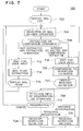
- FIG. 7 is a flow chart illustrating the operation of the user interface processing part 102 shown in FIG. 11.
- FIG. 13 is a diagram showing an example of a mail flow display
- FIGS. 14A and 14B are diagrams showing examples of workflow definitions obtained through extension and extraction of a mail flow.
- the mail flow shown in FIG. 13 is extracted from the mail transmission audit data storage unit 110 shown in FIG. 1.
- the mail flow has a condition list (mail list) 1302 shown in the upper half area and a mail flow chart 1304 shown in the lower half area.
- the mail list 1302 includes date/time, mail sender activity, a subject and the like, and the mail flow chart 1304 shows the order of mail transmissions.
- the users B and C return it to the user A.
- FIG. 14A shows an extended workflow definition list obtained through extension of the mail flow upon clicking the “mail flow” shown in FIG. 13, and FIG. 14B shows an intersectional workflow definition list obtained through extraction of the mail flow upon clicking the “mail flow” shown on the upper left of FIG. 13.
- FIG. 14A an extended workflow definition chart covering the whole work from the person in charge to the planning person is displayed upon clicking a planning proposal flow in an extended workflow definition area 1402 .
- FIG. 14A shows an extended workflow definition chart covering the whole work from the person in charge to the planning person is displayed upon clicking a planning proposal flow in an extended workflow definition area 1402 .
- the user interface processing part 102 displays the mail list 1302 shown in FIG. 13 (Step 702 ) and waits for an input of a mail or a user operation (Step 704 ).
- a user operation is input, it is checked whether a mail flow of a selected mail is already extracted and whether the user operation is a mail flow extraction operation or a comparison operation (Step 706 ). If the user operation is the mail flow extraction operation or the mail flow is not still extracted, the flow stands by until it is confirmed that a user operation for the extraction is entered (Step 712 ) and thereafter the mail flow extraction part 118 extracts the mail flow (Step 714 ) to display a mail flow chart 1304 (FIG. 13) (Step 716 ).
- Step 706 If the judgement at Step 706 indicates that the operation is a definition comparison operation and if the mail flow is already extracted, a user confirmation input is waited (Step 718 ), and the flow definition comparison part 120 performs a comparison process between the mail flow and workflow definitions (Step 720 ).
- a list of definitions having the matched flows is displayed as the extended workflow definition list 1402 and intersectional workflow definition list 1404 (Step 722 ) to wait for an operation input (Step 708 ).
- Step 708 After a registration operation input or a user operation input is waited for (Step 708 ), if the user selects a flow in the definition list, the selected workflow definition is displayed as a flow definition chart 1406 (FIG. 14), whereas the registration operation is entered, it is checked whether the registration operation is a definition registration operation or an instance registration operation (Step 710 ).
- the definition registration operation the definition registration part 122 registers workflow definitions (Step 724 ).
- the instance registration part 124 registers a workflow instance (Step 726 ). If the operation input is neither the definition registration or the instance registration, the flow waits for a mail/operation selection input (Step 704 ).
- Step 802 it is checked from the mail transmission audit data storage unit 110 whether the selected mail has a reference message.
- the reference message is identified by the reference message ID in the reference message ID field 412 in the mail transmission audit data storage unit 110 which stores mail transmission audit data in the order of transmission. If there is audit data of the reference message, a mail corresponding to the audit data is selected (Step 804 ) and it is checked again whether the selected mail has the reference message (Step 802 ). If there is no audit data of the reference message, the mail sender activity in the audit data of the selected mail is used as a start activity of the mail flow (Step 806 ). The mail sender activity is the activity described in the recipient field 404 of the mail transmission audit data storage unit 110 .
- the reason why the reference message is again checked at Step 802 after the audit data is once selected at Step 804 , is to search the first written mail by checking links of reference messages. Namely, by sequentially searching reference messages, a mail having no reference message can be found which is the first written mail.
- a mail flow shown in a lower area in FIG. 9 is extracted from the mail transmission audit data shown in a higher area in FIG. 9. If a selected mail has a reference message, a mail corresponding to the reference message is selected, whereas if a selected mail has no reference message, the mail sender activity in the selected audit data is used as a mail flow start activity. Mails having the message ID of the start activity as the reference message IDes are searched. If there is such audit data, an arrow is added between the mail sender activity of the first selected audit data and the mail sender activity of the next searched audit data to draw a mail flow. In the example shown in FIG.
- audit data 904 having a message ID a98012001 as the reference message ID of the activity C is selected.
- the activity A which is the mail sender activity of the audit data 904 is used as the flow start activity.
- audit data having the message ID of the selected audit data as its reference message ID is searched from the mail transmission audit data storage unit 110 (Step 808 ) to judge whether there is any such audit data (Step 810 ). If there is such audit data, the sender activity of the searched audit data and an arrow connecting the sender activity of the searched audit data and the sender activity of the selected audit data are added to the mail flow chart (Step 812 ). The selected audit data is replaced by the searched audit data (Step 814 ) to thereafter return to Step 808 whereat the above operations are repeated.
- Step 810 shown in FIG. 8 there is no audit data having the message ID of the selected audit data as its reference message ID
- mail audit data including the same mail sender activity as the mail recipient activity of the first selected audit data and having a later date/time is searched from another branch of the graph (step 816 ). If there is such audit data, an arrow is added between the sender activity of the first selected audit data and the sender activity of the searched sender audit data, whereas if there is no such audit data, the process is terminated.
- FIG. 10 is a flow chart illustrating the operation of the workflow definition comparison part 120 shown in FIG. 1.
- FIGS. 14A and 14B show examples of workflow definitions obtained through extension or extraction of the mail flow.
- a mail flow of a designated mail is selected to show the mail flow such as shown in FIG. 13 (Step 1002 ).
- the workflow definitions are selected as shown in FIG. 14A or 14 B (Step 1004 ).
- the start activity of the mail flow is selected to select a group of activities having the same contents as in the sender field of the start activity, and the contents of the selected first activity are replaced by the selected group name (Step 1005 ). For example, “A” of the mail flow chart shown in FIG. 13 is replaced by “person in charge”.
- the start activity of the replaced mail flow chart is compared with the start activity of the workflow definition chart (Step 1006 ) to check whether they are coincident (Step S 1008 ).
- the start activity of the mail flow chart shown in FIG. 13 is compared with the start activity of the workflow definition chart shown in FIG. 14A or 14 B. If not coincident and there is the next definition, the flow returns to Step 1004 (Step 1018 ) to compare the next definition in a manner similar to the above operation. If coincident, the next activities are selected (Step 1010 ) to repeat the comparison starting at Step 1005 until it becomes that there is no next activity of either mail flow activity or workflow activity. If there is no next activity, it is judged which of the mail flow activity and workflow activity becomes absent (Step 1012 ).
- Step 1014 If the workflow activity becomes absent first, the selected definitions are used as the intersectional workflow (Step 1014 ), whereas if the mail flow activity becomes absent first, the selected definitions are used as the extended workflow (Step 1016 ) to thereafter advance to Step 1018 .
- FIG. 14A shows an example of the extended workflow
- FIG. 14B shows an example of the intersectional workflow.
- the extended workflow includes the mail flow chart whereas the intersectional workflow is included in the mail flow chart.
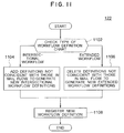
- FIG. 11 is a flow chart illustrating the operation of the workflow definition registration part 122 shown in FIG. 1.
- Step 1102 it is checked whether the workflow definition chart selected at Step 708 shown in FIG. 7 is an extended workflow or an intersectional workflow (Step 1102 ). If the workflow definition chart is the intersectional workflow, the intersectional workflow definitions are compared with the mail flow definitions generated at Step 714 shown in FIG. 7 to thereby add definitions not contained in the intersectional workflow definitions but contained in the mail flow (Step 1104 ). If the workflow definition chart is the extended workflow chart, the extended workflow definitions are compared with the mail flow definitions to thereby delete definitions contained in the extended workflow and not contained in the mail flow (Step 1106 ). The newly formed definitions are registered in the workflow definition storage unit 112 (Step 1108 ).
- FIG. 12 is a flow chart illustrating the operation of the workflow instance registration part 124 shown in FIG. 1.
- Step 1202 it is checked whether the workflow definitions selected at Step S 708 shown in FIG. 7 have a split condition. If not, the flow advances to Step 1208 , whereas if they have a split condition, the condition of the split selected by the mail flow is read (Step 1204 ) to set workflow relevant data of an instance which satisfies the split condition (Step 1206 ). Thereafter, the state of the instance corresponding to the last activity of the mail flow and the a definition ID of the selected workflow definitions are set (Step 1208 ). A unique instance ID is set and the selected mail flow is registered in the workflow instance storage unit 114 as the instance of the selected definitions (Step 1210 ).
- circulation is not required to start from the workflow system, but it can be first started from the mail system and then a workflow instance can be easily entered. It is therefore possible to distribute a load on the workflow system to the mail system. Since the workflow definitions can be easily formed by using audit data of mail circulation, the number of work processes for forming workflow definitions can be reduced. When workflow definitions and instances are generated from the mail flow by referring to already formed workflow definitions, mail flow definitions and workflow definitions are compared on a display screen. It is therefore easy to determine the workflow definitions.
- the invention has the following advantages: (1) Circulation is not required to start from the workflow system, but it can be first started from the mail system and then a workflow instance can be easily entered. It is therefore possible to distribute a load on the workflow system to the mail system. (2) Since the workflow definitions can be easily formed by using audit data of mail circulation, the number of work processes for forming workflow definitions can be reduced. (3) When workflow definitions and instances are generated from the mail flow by referring to already formed workflow definitions, mail flow definitions and workflow definitions are compared on a display screen. It is therefore easy to determine the workflow definitions. (4) It is possible to register an already entered and circulated workflow as an instance of other similar workflow definitions. Therefore, even an instance whose processes are not still determined to the last process, can be processed as a workflow instance. (5) Furthermore, since the composition relationship of workflow definitions can be obtained, management of workflow definitions is easy.
Abstract
In a workflow management system, a mail instance can be easily registered as a workflow instance and workflow definitions, and a workflow instance can be replaced at any process stage by other workflow definitions including present workflow definitions. A mail flow pattern is extracted from a mail transmission audit data storage unit, and a flow definition comparison part compares the mail flow pattern with the flow definitions stored in a workflow definition storage unit. A definition registration part and an instance registration part register the mail flow pattern information as instance information of designated workflow definitions and as new workflow definitions. In accordance with predefined workflow definitions, intersectional workflow definitions and extended workflow definitions corresponding to a mail flow are selected and displayed. The mail flow pattern is registered in the workflow definition storage unit as flow definitions based upon the flow definitions selected from among the displayed workflow definitions.
Description
- 1. Field of the Invention
- The present invention relates to a workflow management method for a system in which works are performed via a network interconnecting user interfaces, and more particularly to a workflow management method for a system in which a combination of a mail system and a workflow management system are operated.
- 2. Description of the Related Art
- In a workflow system, a flow of works by paper documents is changed to a flow of works by electronic chits and books realized on a computer system to perform works of circulation, acceptance and the like. Also in this country, the workflow system is applied to electronic mails, discussion database and the like.
- A known workflow is disclosed, for example, in the article “Substantial Ability of Power Workflow”, at pp. 61-71 in the March 1998 issue of the “Intranet” magazine published by Softbank-Sha. According to this article, the workflow management system defines a flow of works (documents) to automatically circulate the works in accordance with the definitions to thereby shorten the work time and improve the productivity. According to the article, the workflow management system has three constituent elements: workflow definition, execution, and administration. As the workflow definition, an electronic document to be circulated and circulation destinations of the document are defined. As the workflow execution, the document is circulated in accordance with the definitions. As the workflow administration, the process state of the circulated document is recorded to monitor the work progress, and a flow of works is statistically analyzed to provide tools for improving works. A workflow is defined through programming using scripts (language), storing a circulation order in a table, using a chart, or the like.
- An example of a system capable of referring to audit data of sent mails is disclosed, for example, in “Electronic Mail System” of JP-A-7-336385. According to this technique, audit data of electronic mail circulation on a plurality of networks are stored in one storage unit of the networks, and any terminal at the plurality of networks can refer to audit data of mail circulation.
- An approach to managing workflow definitions is disclosed, for example, in “Workflow System” of JP-A-8-123744. According to this technique, workflow definitions are distributed to and independently managed by a plurality of sections and departments, by linking different workflow definitions via input and output ports of each group of workflow definitions.
- The above-described conventional techniques are, however, associated with the following first to third problems.
- First, after an electronic mail document is circulated, work progress is managed. In this case, in order to manage the works as a workflow instance, this workflow instance is required to be newly entered into a computer, -resulting in a complicated operation. The electronic mail system of JP-A-7-336385 cannot generate a workflow instance by using audit data of mail circulation.
- Second, it is not possible to reuse the flow of mail circulation as workflow definitions usable by other users. According to the above-cited article, process definitions corresponding to workflow definitions of this invention are generated by a process definition tool. Even if a flow of once circulated mails is again used with less modification, it is necessary to execute an operation for workflow definitions.
- Third, even a circulated workflow instance cannot be reused as another workflow definition instance including a post-process, when the post-process becomes necessary for the instance. With the workflow system of JP-A-8-123744, when a user of workflow definitions is changed to another user, it is necessary to change the workflow definitions at the input and output ports, and the original workflow definitions cannot be changed at an optional position.
- It is a first object of the present invention to solve the first problem and provide a workflow management method capable of easily registering a mail instance as a workflow instance.
- It is a second object of the present invention to solve the second problem and provide a workflow management method capable of easily registering a mail instance as workflow definitions.
- It is a third object of the present invention to solve the third problem and provide a workflow management method capable of changing a workflow instance at any intermediate process stage to other workflow definitions including current workflow definitions.
- (1) In order to achieve the above objects, in a workflow management method of this invention, audit data of sent mails and mail contents are stored, a mail flow pattern is extracted from the stored audit data of sent mails, the extracted mail flow pattern is compared with preloaded flow definition information to obtain a mail extended workflow or a mail intersectional workflow as a pattern of a workflow, and this pattern is registered as new workflow definitions. Extended workflow definition means workflow definition containing therein an intersectional workflow pattern, and intersectional workflow definition means workflow definition contained in the intersectional workflow pattern.
- (2) In a workflow management method for managing a flow of works by referring to flow definition information of an instance, an extended workflow or an intersectional workflow for workflow definitions of an already entered workflow instance is derived from workflow definition information preloaded in storage means, and the workflow instance is recreated as instance information of the obtained workflow definitions.
- (3) In a workflow management method of this invention, a mail flow of a selected mail is displayed, intersectional workflow definitions and extended workflow definitions matching the mail flow are derived from predefined workflow definitions and displayed, one of the displayed flow definitions is selected, and the mail flow is registered as flow definitions based upon the selected flow definition.
- (4) In a workflow management method of this invention, a mail flow of a selected mail is displayed, intersectional workflow definitions and extended workflow definitions matching the mail flow are derived from predefined workflow definitions and displayed, and the mail flow is registered as an instance of the selected flow definitions.
- (5) In a workflow management method of this invention, a mail flow is displayed, extended workflow definitions and intersectional workflow definitions of the displayed mail flow are displayed, and a workflow instance is recreated as an instance of the extended workflow definitions for workflow definitions which are original definitions of the displayed flow definitions.
- (6) In a workflow management method of the invention, relations between extended workflows and intersectional workflows for a plurality of workflow definitions are stored and managed.
- FIG. 1 is a functional block diagram illustrating a workflow management method according to a first embodiment of the invention.
- FIG. 2 is a functional block diagram illustrating a workflow management method according to a second embodiment of the invention.
- FIG. 3 is a diagram showing an example of a mail box according to the invention.
- FIG. 4 is a diagram showing an example of audit data of sent mails according to the invention.
- FIG. 5 is a diagram showing an example of workflow definitions.
- FIG. 6 is a diagram showing an example of a workflow instance according to the invention.
- FIG. 7 is a flow chart illustrating an operation of a user interface processing part shown in FIG. 1.
- FIG. 8 is a flow chart illustrating an operation of a mail flow extracting part shown in FIG. 1.
- FIG. 9 is a diagram showing an example of a mail flow corresponding to audit data of sent mails according to the invention.
- FIG. 10 is a flow chart illustrating a matching process to be executed by a workflow definition comparison part shown in FIG. 1.
- FIG. 11 is a flow chart illustrating a process of a workflow definition registration part shown in FIG. 1.
- FIG. 12 is a flow chart illustrating a process of a workflow instance registration part shown in FIG. 1.
- FIG. 13 is a diagram showing an example of a mail flow display according to the invention.
- FIG. 14A is a diagram showing an example of a workflow definition display obtained through extension of a mail flow according to the invention.
- FIG. 14B is a diagram showing an example of a workflow definition display obtained through extraction of a mail flow according to the invention.
- Embodiments of the invention will be described in detail with reference to the accompanying drawings.
- (1st Embodiment)
- FIG. 1 is a functional block diagram illustrating a workflow management method according to the first embodiment of the invention. The functions illustrated in FIG. 1 are provided by a server of a client-server system realizing a workflow system.
- Of the blocks shown in FIG. 1, a
mail box 108, a mail transmission auditdata storage unit 110, a workflowdefinition storage unit 112 and a workflowinstance storage unit 114 are hardware having a storage function, and the other blocks including a userinterface processing part 102, amail system 104, aworkflow engine 106 and a flowpattern processing part 116 are all software which executes programs. Themail system 104 andworkflow engine 106 provide known functions. - The user
interface processing part 102 calls a mail transmission/reception acceptance part 103 of themail system 104 via a connection link. If a call is a mail transmission request, the mail transmission/reception acceptance part 103 calls amail delivery part 105 which analyzes the contents of a mail to be transmitted and stores the mail in a mail box of a user who is specified by the contents of the mail or the address of the mail in themail box 108. After the mail is delivered by themail delivery part 105, an audit data recording part 107 stores assignment audit data in the mail transmission auditdata storage unit 110. If a call is a mail reception request, the mail transmission/reception acceptance part 103 acquires a mail corresponding to a called user from themail box 108 and outputs it to the userinterface processing part 102. - The user
interface processing part 102 also calls an instance transmission/reception acceptance part 109 of theworkflow engine 106 via a connection link. If a call is an instance transmission (transition) request, the instance transmission/reception acceptance part 109 calls aninstance assignment part 111. Theinstance assignment part 111 acquires workflow definitions corresponding to an instance to be transmitted, from the workflowdefinition storage unit 112, determines a next assignment user to which the instance is delivered, in accordance with the workflow definition, and updates the workflowinstance storage unit 114 so that the instance becomes an object to be processed by the next assignment user. If a call is an instance reception request, the instance transmission/reception acceptance part 109 acquires an instance corresponding to the called user from the workflowinstance storage unit 114 and outputs it to the userinterface processing part 102. - The
user interface part 102 also calls the flow pattern processing unit part 115 via a directly connected link, reads information from themail box 108, mail transmission/reception auditdata storage unit 110 or workflowdefinition storage unit 112, and writes workflow definition information into the workflowdefinition storage unit 112 and a workflow instance into the workflowinstance storage unit 114. - The flow-
pattern processing part 116 includes a mailflow extraction part 118, a flowdefinition comparison part 120, adefinition registration part 122 and aninstance registration part 124. The invention is characterized in the provision of the flow pattern. processingpart 116 which is realized by programs providing the functions of theseparts flow extraction part 118, flow definitioncomparison unit part 120,definition registration part 122 andinstance registration part 124 are shown respectively in FIGS. 8, 10, 11 and 12. - FIG. 3 shows an example of data stored in the
mail box 108 shown in FIG. 1. - As shown in FIG. 3, the
mail box 108 is constituted of auser list 302 and userspecific mail boxes 304 assigned to respective users corresponding to fields of thelist 302. In this example shown in FIG. 3,mail boxes 304 for users A and B are shown. The userspecific mail box 304 is constituted of amail sender field 306, a mailsubject field 308, a carboncopy recipient field 310, amessage ID field 312, a reference message (message for reference to the mail)ID field 314, and amail content field 315. Themessage ID field 312 is an identifier which the mail system uniquely assigns to each mail. In this example shown in FIG. 3, the messages b98012001 and c98012101 of users B and C in themail sender field 306, supplied to users C and B in the carbon copyrecipient ID field 310, make reference to a similar message a98012001 of user A in the referencemessage ID field 314. In other words, this example shows a case where a mail having the message ID b98012001 and the mail sender B and referring to the message ID a98012001, and a mail having the message ID c98012101 and the mail sender C and referring to the message ID a98012001 are stored in themail box 108. - FIG. 4 shows an example of data stored in the mail transmission audit
data storage unit 110 shown in FIG. 1. - As shown in FIG. 4, the mail transmission audit
data storage unit 110 is constituted of a mail transmission date/time field 402, amail sender field 404, a mail recipient field 406, a carbon copy recipient field 408, amessage ID field 410, a referencemessage ID field 412, and a mailsubject field 414. In the example shown in FIG. 4, mail transmission audit data of three days from Jan. 20, 1998 13:00 to Jan. 22, 1998 13:00 is given. - FIG. 5 shows an example of workflow definitions stored in the workflow
definition storage unit 112 shown in FIG. 1. - As shown in FIG. 5, the
workflow definitions 112 are constituted of activities representative of processes such as those indicated at 502 and 506 and arrows representative of process flows such as those indicated at 504. Of the activities representative of processes, theactivities 502 are work activities corresponding to users including persons in charge and supervisors, and theactivities 506 are control activities whereat a split condition is made to change the process flow. In the lower right area in FIG. 5, a correspondence table is provided which showsassignments 508 at each activity andcorresponding workers 510. A, M and N are persons in charge, B and P are section managers, C is a department manager, and D is a planning person. After an instance is passed from aperson 1 in charge to asection manager 1 and adepartment manager 1, revised or accepted instances are collected at aperson 2 in charge. If the instance is accepted by asection manager 2, it is passed to adepartment manager 2. If thedepartment manager 2 does not accept it, the instance is returned to theperson 2 in charge. If the instance is accepted by thedepartment manager 2, it is passed to a planning person, whereas if it is not accepted, the instance is again returned to theperson 2 in charge. - FIG. 6 shows an example of instance information stored in the workflow
instance storage unit 114 shown in FIG. 1. - As shown in FIG. 6, instance information is constituted of an
instance ID 602, adefinition ID 604, astate 606, workflowrelevant data 608 andadditive information 610. When an instance is generated, theworkflow engine 106 assigns the instance a unique ID and changes the state each time the circulation destination of the instance is changed. In accordance with the workflow relevant data and workflow definition set by workers, theworkflow engine 106 determines the next circulation destination or destinations. In the example shown in FIG. 6, after AA0001 and 0001 are allocated as theinstance ID 602 anddefinition ID 604, the instance is passed to thesection manager 2 shown in FIG. 5 as indicated by thestate 606 and accepted by thesection manager 2 as indicated by the workflowrelevant data 608, and a planning document is designated as theadditive information 610. - Next, the operation of the workflow management method of this invention to be executed in response to a user operation will be described with reference to FIGS. 7, 13 and 14.
- FIG. 7 is a flow chart illustrating the operation of the user
interface processing part 102 shown in FIG. 11. FIG. 13 is a diagram showing an example of a mail flow display, and FIGS. 14A and 14B are diagrams showing examples of workflow definitions obtained through extension and extraction of a mail flow. - The mail flow shown in FIG. 13 is extracted from the mail transmission audit
data storage unit 110 shown in FIG. 1. As shown in FIG. 13, the mail flow has a condition list (mail list) 1302 shown in the upper half area and amail flow chart 1304 shown in the lower half area. Themail list 1302 includes date/time, mail sender activity, a subject and the like, and themail flow chart 1304 shows the order of mail transmissions. In this example shown in FIG. 13, after an instance is transmitted from user A to users B and C, the users B and C return it to the user A. - FIG. 14A shows an extended workflow definition list obtained through extension of the mail flow upon clicking the “mail flow” shown in FIG. 13, and FIG. 14B shows an intersectional workflow definition list obtained through extraction of the mail flow upon clicking the “mail flow” shown on the upper left of FIG. 13. In the example shown in FIG. 14A, an extended workflow definition chart covering the whole work from the person in charge to the planning person is displayed upon clicking a planning proposal flow in an extended
workflow definition area 1402. In the example shown in FIG. 14B, only a portion wherein an instance is passed from a person in charge to a section manager and a department manager and a presence/absence of a comment on a business trip report is returned to the person in charge, is extracted from the whole flow, upon clicking a business report flow in an intersectionalworkflow definition area 1404. - Referring to FIG. 7, the user
interface processing part 102 displays themail list 1302 shown in FIG. 13 (Step 702) and waits for an input of a mail or a user operation (Step 704). Upon a user operation is input, it is checked whether a mail flow of a selected mail is already extracted and whether the user operation is a mail flow extraction operation or a comparison operation (Step 706). If the user operation is the mail flow extraction operation or the mail flow is not still extracted, the flow stands by until it is confirmed that a user operation for the extraction is entered (Step 712) and thereafter the mailflow extraction part 118 extracts the mail flow (Step 714) to display a mail flow chart 1304 (FIG. 13) (Step 716). - If the judgement at
Step 706 indicates that the operation is a definition comparison operation and if the mail flow is already extracted, a user confirmation input is waited (Step 718), and the flowdefinition comparison part 120 performs a comparison process between the mail flow and workflow definitions (Step 720). - With this process, as shown in FIGS. 14A and 14B, a list of definitions having the matched flows is displayed as the extended
workflow definition list 1402 and intersectional workflow definition list 1404 (Step 722) to wait for an operation input (Step 708). - After a registration operation input or a user operation input is waited for (Step 708), if the user selects a flow in the definition list, the selected workflow definition is displayed as a flow definition chart 1406 (FIG. 14), whereas the registration operation is entered, it is checked whether the registration operation is a definition registration operation or an instance registration operation (Step 710). In the case of the definition registration operation, the
definition registration part 122 registers workflow definitions (Step 724). In the case of the instance registration operation, theinstance registration part 124 registers a workflow instance (Step 726). If the operation input is neither the definition registration or the instance registration, the flow waits for a mail/operation selection input (Step 704). - Next, with reference to FIGS. 8 and 9, the detailed operation of the mail
flow extraction part 714 will be described. - FIG. 8 is a flow chart illustrating an operation of extracting a mail flow from the mail transmission audit
data storage unit 110 shown in FIG. 1. FIG. 9 is a diagram illustrating how a mail flow stored in thestorage unit 110 is extracted. - First, it is checked from the mail transmission audit
data storage unit 110 whether the selected mail has a reference message (Step 802). As shown in FIG. 9, the reference message is identified by the reference message ID in the referencemessage ID field 412 in the mail transmission auditdata storage unit 110 which stores mail transmission audit data in the order of transmission. If there is audit data of the reference message, a mail corresponding to the audit data is selected (Step 804) and it is checked again whether the selected mail has the reference message (Step 802). If there is no audit data of the reference message, the mail sender activity in the audit data of the selected mail is used as a start activity of the mail flow (Step 806). The mail sender activity is the activity described in therecipient field 404 of the mail transmission auditdata storage unit 110. - The reason why the reference message is again checked at
Step 802 after the audit data is once selected atStep 804, is to search the first written mail by checking links of reference messages. Namely, by sequentially searching reference messages, a mail having no reference message can be found which is the first written mail. - The above operations will be described specifically with reference to FIG. 9. A mail flow shown in a lower area in FIG. 9 is extracted from the mail transmission audit data shown in a higher area in FIG. 9. If a selected mail has a reference message, a mail corresponding to the reference message is selected, whereas if a selected mail has no reference message, the mail sender activity in the selected audit data is used as a mail flow start activity. Mails having the message ID of the start activity as the reference message IDes are searched. If there is such audit data, an arrow is added between the mail sender activity of the first selected audit data and the mail sender activity of the next searched audit data to draw a mail flow. In the example shown in FIG. 9, assuming that
audit data 902 having the message ID of c98012101 of the activity C is first selected,audit data 904 having a message ID a98012001 as the reference message ID of the activity C is selected. In this case, since theaudit data 904 has no reference message, the activity A (906) which is the mail sender activity of theaudit data 904 is used as the flow start activity. - Reverting to FIG. 8, audit data having the message ID of the selected audit data as its reference message ID is searched from the mail transmission audit data storage unit 110 (Step 808) to judge whether there is any such audit data (Step 810). If there is such audit data, the sender activity of the searched audit data and an arrow connecting the sender activity of the searched audit data and the sender activity of the selected audit data are added to the mail flow chart (Step 812). The selected audit data is replaced by the searched audit data (Step 814) to thereafter return to
Step 808 whereat the above operations are repeated. - The above operations will be described with reference to FIG. 9. As the audit data having the message ID of a98012001 of the
mail audit data 904 of the sender activity A, there are two sets ofaudit data audit data 910 has the message ID of theaudit data 908 as its reference message ID, an arrow is added between the activities B and A from B to A. Similarly, activities B, C and D and arrows between A and B, between B and C and between C and D are added. - If at
Step 810 shown in FIG. 8 there is no audit data having the message ID of the selected audit data as its reference message ID, mail audit data including the same mail sender activity as the mail recipient activity of the first selected audit data and having a later date/time is searched from another branch of the graph (step 816). If there is such audit data, an arrow is added between the sender activity of the first selected audit data and the sender activity of the searched sender audit data, whereas if there is no such audit data, the process is terminated. - The above operations will be described with reference to FIG. 9. Since there is no mail audit data having as its reference message the
audit data 902 of the sender activity C, audit data including the recipient activity A of theaudit data 902 and having a later date/time is searched. The sender activity oraudit data 910 is such audit data, so that an arrow is added between the sender activity C (912) of theaudit data 902 and the sender activity A (914) of theaudit data 910. With the above operations, amail flow 916 shown in FIG. 9 can be generated. - Next, the detailed operation to be executed by the workflow
definition comparison part 120 will be described with reference to FIGS. 10 and 14. - FIG. 10 is a flow chart illustrating the operation of the workflow
definition comparison part 120 shown in FIG. 1. FIGS. 14A and 14B show examples of workflow definitions obtained through extension or extraction of the mail flow. - First, a mail flow of a designated mail is selected to show the mail flow such as shown in FIG. 13 (Step 1002). The workflow definitions are selected as shown in FIG. 14A or 14B (Step 1004). Next, the start activity of the mail flow is selected to select a group of activities having the same contents as in the sender field of the start activity, and the contents of the selected first activity are replaced by the selected group name (Step 1005). For example, “A” of the mail flow chart shown in FIG. 13 is replaced by “person in charge”. Next, the start activity of the replaced mail flow chart is compared with the start activity of the workflow definition chart (Step 1006) to check whether they are coincident (Step S1008). For example, the start activity of the mail flow chart shown in FIG. 13 is compared with the start activity of the workflow definition chart shown in FIG. 14A or 14B. If not coincident and there is the next definition, the flow returns to Step 1004 (Step 1018) to compare the next definition in a manner similar to the above operation. If coincident, the next activities are selected (Step 1010) to repeat the comparison starting at
Step 1005 until it becomes that there is no next activity of either mail flow activity or workflow activity. If there is no next activity, it is judged which of the mail flow activity and workflow activity becomes absent (Step 1012). If the workflow activity becomes absent first, the selected definitions are used as the intersectional workflow (Step 1014), whereas if the mail flow activity becomes absent first, the selected definitions are used as the extended workflow (Step 1016) to thereafter advance toStep 1018. - FIG. 14A shows an example of the extended workflow, and FIG. 14B shows an example of the intersectional workflow. As compared to the
mail flow chart 1304 shown in FIG. 13, the extended workflow includes the mail flow chart whereas the intersectional workflow is included in the mail flow chart. - Next, the operation of the workflow
definition registration part 122 will be described. - FIG. 11 is a flow chart illustrating the operation of the workflow
definition registration part 122 shown in FIG. 1. - First, it is checked whether the workflow definition chart selected at
Step 708 shown in FIG. 7 is an extended workflow or an intersectional workflow (Step 1102). If the workflow definition chart is the intersectional workflow, the intersectional workflow definitions are compared with the mail flow definitions generated atStep 714 shown in FIG. 7 to thereby add definitions not contained in the intersectional workflow definitions but contained in the mail flow (Step 1104). If the workflow definition chart is the extended workflow chart, the extended workflow definitions are compared with the mail flow definitions to thereby delete definitions contained in the extended workflow and not contained in the mail flow (Step 1106). The newly formed definitions are registered in the workflow definition storage unit 112 (Step 1108). - Next, the operation of the workflow
instance registration part 124 will be described with reference to FIG. 12. FIG. 12 is a flow chart illustrating the operation of the workflowinstance registration part 124 shown in FIG. 1. - First, it is checked whether the workflow definitions selected at Step S 708 shown in FIG. 7 have a split condition (Step 1202). If not, the flow advances to Step 1208, whereas if they have a split condition, the condition of the split selected by the mail flow is read (Step 1204) to set workflow relevant data of an instance which satisfies the split condition (Step 1206). Thereafter, the state of the instance corresponding to the last activity of the mail flow and the a definition ID of the selected workflow definitions are set (Step 1208). A unique instance ID is set and the selected mail flow is registered in the workflow
instance storage unit 114 as the instance of the selected definitions (Step 1210). - As described above, according to this embodiment, circulation is not required to start from the workflow system, but it can be first started from the mail system and then a workflow instance can be easily entered. It is therefore possible to distribute a load on the workflow system to the mail system. Since the workflow definitions can be easily formed by using audit data of mail circulation, the number of work processes for forming workflow definitions can be reduced. When workflow definitions and instances are generated from the mail flow by referring to already formed workflow definitions, mail flow definitions and workflow definitions are compared on a display screen. It is therefore easy to determine the workflow definitions.
- In the above embodiment, a combination of the mail system and workflow system is used. The invention is also applicable to only a workflow system. In the following, a second embodiment applying the invention only to a workflow system will be described.
- (2nd Embodiment)
- FIG. 2 is a functional block diagram illustrating a workflow management method according to the second embodiment of the invention.
- The configuration of the second embodiment is simplified more than that shown in FIG. 1. This system is constituted of a user
interface processing part 102, aworkflow engine 106, a workflowdefinition storage unit 112, a workflowinstance storage unit 114, a workflow auditdata storage unit 202, and a flowpattern processing part 116 made of a flowdefinition comparison part 120 and aninstance registration part 124. The userinterface processing part 102,workflow engine 106 and flowpattern processing part 116 other than thestorage units - The user
interface processing part 102 calls an instance transmission/reception acceptance part 109 of theworkflow engine 106 via a connection link. If a call is an instance transmission (transition) request, the instance transmission/reception acceptance part 109 calls aninstance assignment part 111. Theinstance assignment part 111 acquires workflow definitions corresponding to an instance to be transmitted, from the workflowdefinition storage unit 112, determines a next assignment user to which the instance is delivered, in accordance with the workflow definition, and updates the workflowinstance storage unit 114 so that the instance becomes an object to be processed by the next assignment user. If a call is an instance reception request, the instance transmission/reception acceptance part 109 acquires an instance corresponding to the called user from the workflowinstance storage unit 114 and outputs it to the userinterface processing part 102. - Data stored in the workflow audit
data storage unit 202 is similar to that stored in the mail transmission auditdata storage unit 110 shown in FIG. 1. However, the reference message ID and message ID are replaced by an instance ID. - In this embodiment, it is possible to register an already entered and circulated workflow as an instance of other similar workflow definitions. Therefore, even an instance whose processes are not still determined to the last process, can be processed as a workflow instance. Furthermore, since the composition relationship of workflow definitions can be obtained, management of workflow definitions is easy.
- In the system shown in FIG. 2, a workflow instance is processed and workflow definitions corresponding to the instance are already present. Therefore, it is not necessary as in the case of mail analysis in the system shown in FIG. 1 to extract workflow definitions and register them.
- As described so far, the invention has the following advantages: (1) Circulation is not required to start from the workflow system, but it can be first started from the mail system and then a workflow instance can be easily entered. It is therefore possible to distribute a load on the workflow system to the mail system. (2) Since the workflow definitions can be easily formed by using audit data of mail circulation, the number of work processes for forming workflow definitions can be reduced. (3) When workflow definitions and instances are generated from the mail flow by referring to already formed workflow definitions, mail flow definitions and workflow definitions are compared on a display screen. It is therefore easy to determine the workflow definitions. (4) It is possible to register an already entered and circulated workflow as an instance of other similar workflow definitions. Therefore, even an instance whose processes are not still determined to the last process, can be processed as a workflow instance. (5) Furthermore, since the composition relationship of workflow definitions can be obtained, management of workflow definitions is easy.
Claims (12)
1. A workflow management method for managing mail transmission/reception and a flow of works in accordance with workflow definition information for defining a flow of works, the method comprising the steps of:
a) storing mail transmission audit data;
b) comparing pattern information of a mail flow derived from the mail transmission audit data with preloaded workflow definition information, to obtain an extended workflow or an intersectional workflow of the mail flow; and
c) registering the mail flow pattern information including the extended workflow or the intersectional workflow in the workflow definition information as new workflow definition information.
2. A workflow management method for managing a flow of works in accordance with workflow definition information for defining a flow of works, the method comprising the steps of:
deriving an extended workflow or an intersectional workflow of workflow definitions of an already circulated workflow instance from workflow definition information stored in storage means; and
recreating the workflow instance as instance information of the workflow definitions derived from the storage means.
3. A workflow management method according to claim 1 , wherein said step c) comprises the subsidiary steps of:
c1) displaying a mail flow selected from the mail transmission audit data;
c2) displaying intersectional workflow definitions or extended workflow definitions in predefined workflow definitions matching the mail flow; and
c3) registering the mail flow as new flow definitions based upon the flow definition selected from the displayed flow definitions.
4. A workflow management method according to claim 1 , wherein said step b) comprises the subsidiary steps of:
b1) judging whether there is a reference message which refers to a selected mail, when the mail flow is derived from the mail transmission audit data;
b2) if there is audit data having the reference message, selecting a mail corresponding to the history;
b3) if there is no audit data having the reference message, setting a sender activity of the audit data of the selected mail as a start activity of the mail flow to be derived;
b4) searching audit data containing a message identifier of the selected audit data as an identifier of the reference message, from the mail transmission audit data;
b5) if there is such audit data, adding an arrow between the sender activity of the selected audit data and the sender activity of the searched audit data;
b6) replacing the selected audit data by the searched audit data and repeating said steps b4) and b5);
b7) if there is no audit data containing a message identifier of the selected audit data as an identifier of the reference message, searching from another graph branch mail audit data having a sender activity same as the sender activity of the selected audit data and a later date and time; and
b8) if a search result indicates that there is such audit data, adding an arrow between the sender activity of the selected audit data and the sender activity of the searched audit data.
5. A workflow management method according to claim 1 , wherein said step c) comprises the subsidiary steps of:
c1) judging whether the workflow definition information selected from storage means is an extended workflow or an intersectional workflow;
c2) if the intersectional workflow, comparing the intersectional workflow definitions with the mail flow derived from the stored mail transmission audit data, and generating flow definitions by adding definitions not present in the mail flow from the intersectional workflow definitions;
c3) if the extended workflow, comparing extended workflow definitions with the mail flow derived from the stored mail transmission audit data, and generating flow definitions by deleting definitions not present in the mail flow from the extended workflow definitions; and
c4) registering the flow definitions generated at said step c2) or c3) as new workflow definitions.
6. A workflow management method using a processing apparatus, comprising the steps of:
deriving a mail flow from stored mail transmission audit data or from contents of mails;
selecting workflow definitions from storage means and checking whether the workflow definitions have a split condition;
if there is a split condition, reading the split condition selected by the mail flow and setting workflow relevant data of an instance satisfying the split condition;
setting a state of the instance corresponding to a last activity of the mail flow and a definition identifier of the selected workflow definitions; and
registering the selected mail flow as an instance of the selected workflow definitions.
7. A storage medium storing a program for a processing apparatus to execute a workflow management method for managing mail transmission/reception and a flow of works in accordance with workflow definition information for defining a flow of works, the method comprising the steps of:
a) storing mail transmission audit data;
b) comparing pattern information of a mail flow derived from the mail transmission audit data with preloaded workflow definition information, to obtain an extended workflow or an intersectional workflow of the mail flow; and
c) registering the mail flow pattern information including the extended workflow or the intersectional workflow in the workflow definition information as new workflow definition information.
8. A workflow management method using a processing apparatus comprising the steps of:
a) comparing flow pattern information of electronic mails derived from mail transmission audit data with preloaded workflow definition information; and
b) in accordance with a comparison result, registering the flow pattern information to the workflow definition information as new workflow definitions.
9. A workflow management method using a processing apparatus comprising the steps of:
a) comparing flow definitions in flow pattern information of electronic mails derived from mail transmission audit data with flow definitions in preloaded workflow definition information; and
b) if the flow definitions are coincident, registering the flow pattern information to the workflow definition information as new workflow definitions.
10. A workflow management system for managing mail transmission/reception and a flow of works in accordance with workflow definition information for defining a flow of works, comprising:
a) means for storing mail transmission audit data;
b) means for comparing pattern information of a mail flow derived from the mail transmission audit data with preloaded workflow definition information, to obtain an extended workflow or an intersectional workflow of the mail flow; and
c) means for registering the mail flow pattern information including the extended workflow or the, intersectional workflow in the workflow definition information as new workflow definition information.
11. A workflow management method for managing mail transmission/reception and a flow of works in accordance with workflow definition information for defining a flow of works, the method comprising the steps of:
displaying a mail flow of a selected mail;
deriving at least one of intersectional workflow definitions and extended workflow definitions matching the mail flow, of predefined workflow definitions, and displaying the derived flow definitions;
selecting one of the displayed flow definitions; and
registering the mail flow as flow definitions based upon the selected flow definition.
12. A workflow management method for managing mail transmission/reception and a flow of works in accordance with workflow definition information for defining a flow of works, the method comprising the steps of:
displaying a mail flow;
displaying extended workflow definitions and intersectional workflow definitions of the displayed mail flow in accordance with preloaded workflow definitions; and
recreating a workflow instance as an instance of the workflow definitions containing the displayed flow definitions.
Priority Applications (1)
| Application Number | Priority Date | Filing Date | Title |
|---|---|---|---|
| US10/448,411 US20030195782A1 (en) | 1998-07-23 | 2003-05-30 | Method for managing workflow based on electronic mail system |
Applications Claiming Priority (4)
| Application Number | Priority Date | Filing Date | Title |
|---|---|---|---|
| JP20775098A JP2000040104A (en) | 1998-07-23 | 1998-07-23 | Workflow management method |
| JP10-207750 | 1998-07-23 | ||
| US09/357,831 US6594636B1 (en) | 1998-07-23 | 1999-07-21 | Method for managing workflow based on electronic mail system |
| US10/448,411 US20030195782A1 (en) | 1998-07-23 | 2003-05-30 | Method for managing workflow based on electronic mail system |
Related Parent Applications (1)
| Application Number | Title | Priority Date | Filing Date |
|---|---|---|---|
| US09/357,831 Division US6594636B1 (en) | 1998-07-23 | 1999-07-21 | Method for managing workflow based on electronic mail system |
Publications (1)
| Publication Number | Publication Date |
|---|---|
| US20030195782A1 true US20030195782A1 (en) | 2003-10-16 |
Family
ID=16544931
Family Applications (3)
| Application Number | Title | Priority Date | Filing Date |
|---|---|---|---|
| US09/357,831 Expired - Fee Related US6594636B1 (en) | 1998-07-23 | 1999-07-21 | Method for managing workflow based on electronic mail system |
| US10/447,998 Abandoned US20030195781A1 (en) | 1998-07-23 | 2003-05-30 | Method for managing workflow based on electronic mail system |
| US10/448,411 Abandoned US20030195782A1 (en) | 1998-07-23 | 2003-05-30 | Method for managing workflow based on electronic mail system |
Family Applications Before (2)
| Application Number | Title | Priority Date | Filing Date |
|---|---|---|---|
| US09/357,831 Expired - Fee Related US6594636B1 (en) | 1998-07-23 | 1999-07-21 | Method for managing workflow based on electronic mail system |
| US10/447,998 Abandoned US20030195781A1 (en) | 1998-07-23 | 2003-05-30 | Method for managing workflow based on electronic mail system |
Country Status (3)
| Country | Link |
|---|---|
| US (3) | US6594636B1 (en) |
| EP (1) | EP0974919A3 (en) |
| JP (1) | JP2000040104A (en) |
Cited By (8)
| Publication number | Priority date | Publication date | Assignee | Title |
|---|---|---|---|---|
| US20060031358A1 (en) * | 2004-05-27 | 2006-02-09 | Canis Randy L | System and method for managing mail messages |
| US20070112829A1 (en) * | 2005-11-14 | 2007-05-17 | Microsoft Corporation | Databinding workflow data to a user interface layer |
| US20090282367A1 (en) * | 2008-05-06 | 2009-11-12 | Randy Canis | Method and system for electronic communication management |
| US20130018682A1 (en) * | 2011-07-14 | 2013-01-17 | International Business Machines Corporation | Managing Processes In An Enterprise Intelligence ('EI') Assembly Of An EI Framework |
| US20130073557A1 (en) * | 2011-09-21 | 2013-03-21 | Hamid Reza Motahari Nezhad | Matching of cases based on attributes including an attribute relating to flow of activities |
| US20130222845A1 (en) * | 2012-01-13 | 2013-08-29 | Pitney Bowes Inc. | Mail Production Job Tracking System and Method |
| US9646278B2 (en) | 2011-07-14 | 2017-05-09 | International Business Machines Corporation | Decomposing a process model in an enterprise intelligence (‘EI’) framework |
| US9659266B2 (en) | 2011-07-14 | 2017-05-23 | International Business Machines Corporation | Enterprise intelligence (‘EI’) management in an EI framework |
Families Citing this family (22)
| Publication number | Priority date | Publication date | Assignee | Title |
|---|---|---|---|---|
| JP2001344391A (en) * | 2000-05-30 | 2001-12-14 | Satoshi Sagawa | Method of quick construction for work flow system capable of obtaining operation history of activities on operator and function basis characteristic of various organizations |
| US20020174093A1 (en) * | 2001-05-17 | 2002-11-21 | Fabio Casati | Method of identifying and analyzing business processes from workflow audit logs |
| US7941486B2 (en) * | 2002-01-16 | 2011-05-10 | Xerox Corporation | Systems and methods for integrating electronic mail and distributed networks into a workflow system |
| US20040148299A1 (en) * | 2002-11-25 | 2004-07-29 | Microsoft Corporation | Automated workflow composable action model |
| US20040103014A1 (en) * | 2002-11-25 | 2004-05-27 | Teegan Hugh A. | System and method for composing and constraining automated workflow |
| US7062537B2 (en) * | 2002-11-25 | 2006-06-13 | Microsoft Corporation | Workflow services architecture |
| US20040148213A1 (en) * | 2002-11-25 | 2004-07-29 | Microsoft Corporation | Automated workflow constraints |
| FR2862781B1 (en) * | 2003-11-21 | 2006-03-17 | France Telecom | METHOD FOR AUTOMATICALLY MANAGING ELECTRONIC MESSAGING |
| JP4625337B2 (en) * | 2004-02-23 | 2011-02-02 | 株式会社リコー | Process management apparatus, process management method, and process management program |
| JP2006185316A (en) * | 2004-12-28 | 2006-07-13 | Fujitsu Ltd | Business analysis support program, device and method |
| JP4506569B2 (en) * | 2005-06-02 | 2010-07-21 | 日本電気株式会社 | Distributed application service management system, method, and program, and simulation apparatus, method, and program |
| JP4752356B2 (en) * | 2005-06-28 | 2011-08-17 | 富士ゼロックス株式会社 | History providing device |
| US20070162318A1 (en) * | 2005-11-08 | 2007-07-12 | Kaulkin Information Systems, Llc | System And Method For Managing Business Processes |
| JP4796185B2 (en) * | 2007-05-25 | 2011-10-19 | 富士通株式会社 | Business flow diagram generation program, business flow diagram generation device, and business flow diagram generation method |
| JP2008041103A (en) * | 2007-09-03 | 2008-02-21 | Fuji Xerox Co Ltd | Information retrieval support device |
| US8468529B2 (en) * | 2009-05-27 | 2013-06-18 | Microsoft Corporation | Correlating, logging and tracing messaging events between workflow instances with globally unique identifiers |
| US8874525B2 (en) * | 2011-04-19 | 2014-10-28 | Autodesk, Inc. | Hierarchical display and navigation of document revision histories |
| CN102724135A (en) * | 2011-12-14 | 2012-10-10 | 新奥特(北京)视频技术有限公司 | Workflow mail synchronization method |
| JP6157375B2 (en) * | 2014-02-07 | 2017-07-05 | Kddi株式会社 | Operation procedure flow update device, method and program |
| JP7180342B2 (en) * | 2018-12-06 | 2022-11-30 | コニカミノルタ株式会社 | A workflow model generation system, a workflow model generation program, and a workflow model generation method. |
| US11134047B2 (en) * | 2019-03-28 | 2021-09-28 | Kyocera Document Solutions Inc. | System and method of communication between email plugins |
| CN110163558A (en) * | 2019-04-16 | 2019-08-23 | 平安科技(深圳)有限公司 | The examination and approval document measures and procedures for the examination and approval, device, computer equipment and storage medium |
Citations (4)
| Publication number | Priority date | Publication date | Assignee | Title |
|---|---|---|---|---|
| US5627764A (en) * | 1991-10-04 | 1997-05-06 | Banyan Systems, Inc. | Automatic electronic messaging system with feedback and work flow administration |
| US5937388A (en) * | 1996-12-05 | 1999-08-10 | Hewlett-Packard Company | System and method for performing scalable distribution of process flow activities in a distributed workflow management system |
| US6041306A (en) * | 1996-12-05 | 2000-03-21 | Hewlett-Packard Company | System and method for performing flexible workflow process execution in a distributed workflow management system |
| US6154753A (en) * | 1995-09-15 | 2000-11-28 | Cable & Wireless, Inc. | Document management system and method for business quality modeling |
Family Cites Families (9)
| Publication number | Priority date | Publication date | Assignee | Title |
|---|---|---|---|---|
| FR1028782A (en) * | 1949-10-31 | 1953-05-27 | Glanzstoff Courtaulds Gmbh | Process for the preparation of cellulose xanthogenate |
| GB2263988B (en) * | 1992-02-04 | 1996-05-22 | Digital Equipment Corp | Work flow management system and method |
| JP3649345B2 (en) * | 1994-05-26 | 2005-05-18 | 富士ゼロックス株式会社 | Information processing system |
| JPH07336385A (en) | 1994-06-07 | 1995-12-22 | Hitachi Inf Syst Ltd | Electronic mail system |
| US5745687A (en) * | 1994-09-30 | 1998-04-28 | Hewlett-Packard Co | System for distributed workflow in which a routing node selects next node to be performed within a workflow procedure |
| JPH08123744A (en) | 1994-10-26 | 1996-05-17 | Hitachi Ltd | Work flow system |
| JPH10207750A (en) * | 1997-01-20 | 1998-08-07 | Hitachi Ltd | Computer system for changing storage form of external storage |
| US5978836A (en) * | 1997-07-28 | 1999-11-02 | Solectron Corporation | Workflow systems and methods |
| US6119149A (en) * | 1998-06-05 | 2000-09-12 | I2 Technologies, Inc. | System and process allowing collaboration within and between enterprises for optimal decision making |
-
1998
- 1998-07-23 JP JP20775098A patent/JP2000040104A/en active Pending
-
1999
- 1999-07-19 EP EP99114030A patent/EP0974919A3/en not_active Withdrawn
- 1999-07-21 US US09/357,831 patent/US6594636B1/en not_active Expired - Fee Related
-
2003
- 2003-05-30 US US10/447,998 patent/US20030195781A1/en not_active Abandoned
- 2003-05-30 US US10/448,411 patent/US20030195782A1/en not_active Abandoned
Patent Citations (4)
| Publication number | Priority date | Publication date | Assignee | Title |
|---|---|---|---|---|
| US5627764A (en) * | 1991-10-04 | 1997-05-06 | Banyan Systems, Inc. | Automatic electronic messaging system with feedback and work flow administration |
| US6154753A (en) * | 1995-09-15 | 2000-11-28 | Cable & Wireless, Inc. | Document management system and method for business quality modeling |
| US5937388A (en) * | 1996-12-05 | 1999-08-10 | Hewlett-Packard Company | System and method for performing scalable distribution of process flow activities in a distributed workflow management system |
| US6041306A (en) * | 1996-12-05 | 2000-03-21 | Hewlett-Packard Company | System and method for performing flexible workflow process execution in a distributed workflow management system |
Cited By (12)
| Publication number | Priority date | Publication date | Assignee | Title |
|---|---|---|---|---|
| US20060031358A1 (en) * | 2004-05-27 | 2006-02-09 | Canis Randy L | System and method for managing mail messages |
| US20070112829A1 (en) * | 2005-11-14 | 2007-05-17 | Microsoft Corporation | Databinding workflow data to a user interface layer |
| US7606824B2 (en) * | 2005-11-14 | 2009-10-20 | Microsoft Corporation | Databinding workflow data to a user interface layer |
| US20090282367A1 (en) * | 2008-05-06 | 2009-11-12 | Randy Canis | Method and system for electronic communication management |
| US20130018682A1 (en) * | 2011-07-14 | 2013-01-17 | International Business Machines Corporation | Managing Processes In An Enterprise Intelligence ('EI') Assembly Of An EI Framework |
| US9639815B2 (en) * | 2011-07-14 | 2017-05-02 | International Business Machines Corporation | Managing processes in an enterprise intelligence (‘EI’) assembly of an EI framework |
| US9646278B2 (en) | 2011-07-14 | 2017-05-09 | International Business Machines Corporation | Decomposing a process model in an enterprise intelligence (‘EI’) framework |
| US9659266B2 (en) | 2011-07-14 | 2017-05-23 | International Business Machines Corporation | Enterprise intelligence (‘EI’) management in an EI framework |
| US20130073557A1 (en) * | 2011-09-21 | 2013-03-21 | Hamid Reza Motahari Nezhad | Matching of cases based on attributes including an attribute relating to flow of activities |
| US9646054B2 (en) * | 2011-09-21 | 2017-05-09 | Hewlett Packard Enterprise Development Lp | Matching of cases based on attributes including an attribute relating to flow of activities |
| US20130222845A1 (en) * | 2012-01-13 | 2013-08-29 | Pitney Bowes Inc. | Mail Production Job Tracking System and Method |
| US9690530B2 (en) * | 2012-01-13 | 2017-06-27 | Pitney Bowes Inc. | Mail production job tracking system and method |
Also Published As
| Publication number | Publication date |
|---|---|
| EP0974919A2 (en) | 2000-01-26 |
| US6594636B1 (en) | 2003-07-15 |
| JP2000040104A (en) | 2000-02-08 |
| US20030195781A1 (en) | 2003-10-16 |
| EP0974919A3 (en) | 2001-02-28 |
Similar Documents
| Publication | Publication Date | Title |
|---|---|---|
| US6594636B1 (en) | Method for managing workflow based on electronic mail system | |
| US7729924B2 (en) | Virtual knowledge management system | |
| US8219431B2 (en) | Workflow management system, method and device for managing a workflow including plural hierarchically-classified tasks | |
| CN110717320A (en) | Form/report designer and method suitable for multiple platforms and information management system | |
| JP5475203B1 (en) | Workflow management apparatus and workflow management method | |
| US20030189600A1 (en) | Defining an approval process for requests for approval | |
| US20050159968A1 (en) | Organizationally interactive task management and commitment management system in a matrix based organizational environment | |
| US20030014294A1 (en) | Job offer/job seeker information processing system | |
| JP2002024495A (en) | Schedule management system | |
| JPH0777380B2 (en) | E-mail tracking system | |
| US20060235861A1 (en) | Apparatus, system and method for supporting formation of customer-value creating scenario | |
| KR20070113168A (en) | System construction guide system | |
| US20020007375A1 (en) | Document management method and computer-readable storage medium storing program code for executing the same | |
| JP2008250558A (en) | Workflow management system, workflow management method, retrieval system, retrieval method, and program | |
| JP2008250556A (en) | Workflow management system, workflow management method, and program | |
| JPH1185880A (en) | Work flow system development supporting method | |
| JP2003016019A (en) | Information managing apparatus, communication terminal, information managing system, information managing method, recording medium, and program | |
| JPH1173459A (en) | Work flow management system and method for operating document management | |
| US7412688B2 (en) | Workflow defining system and workflow managing system | |
| JP3225996B2 (en) | Information processing system | |
| US20040216148A1 (en) | Service and support mechanism for delivering electronic customer support services | |
| JP6796444B2 (en) | File distribution system | |
| JPH09305660A (en) | Method and device for defining business process | |
| Datunsolang et al. | Business Process Reengineering Approval Services For Spatial Use Activities | |
| JP2008250557A (en) | Workflow management system, workflow management method and program |
Legal Events
| Date | Code | Title | Description |
|---|---|---|---|
| STCB | Information on status: application discontinuation |
Free format text: ABANDONED -- FAILURE TO PAY ISSUE FEE |