US20030193684A1 - Method and system for diagnosing printing defects - Google Patents
Method and system for diagnosing printing defects Download PDFInfo
- Publication number
- US20030193684A1 US20030193684A1 US10/119,650 US11965002A US2003193684A1 US 20030193684 A1 US20030193684 A1 US 20030193684A1 US 11965002 A US11965002 A US 11965002A US 2003193684 A1 US2003193684 A1 US 2003193684A1
- Authority
- US
- United States
- Prior art keywords
- printing
- sheet
- processor
- printing device
- printed
- Prior art date
- Legal status (The legal status is an assumption and is not a legal conclusion. Google has not performed a legal analysis and makes no representation as to the accuracy of the status listed.)
- Abandoned
Links
Images


Classifications
-
- G—PHYSICS
- G06—COMPUTING; CALCULATING OR COUNTING
- G06K—GRAPHICAL DATA READING; PRESENTATION OF DATA; RECORD CARRIERS; HANDLING RECORD CARRIERS
- G06K15/00—Arrangements for producing a permanent visual presentation of the output data, e.g. computer output printers
- G06K15/02—Arrangements for producing a permanent visual presentation of the output data, e.g. computer output printers using printers
- G06K15/025—Simulating output on another printing arrangement, e.g. proof output
Definitions
- the present invention relates generally to methods and apparatus for providing points of reference for files that are printed on sheets of paper or other media. More specifically, the present invention relates to methods for using such points of reference in manually diagnosing the causes of printing defects that may occur as the files are printed onto the sheets.
- printing is effected by providing a digital file to a printing device, such as a printer, facsimile machine, copy machine, or the like.
- a file to be printed may be accompanied by a so-called “packet”, which may include identifiers for the source device and the intended recipient device, and instructions as to how the file is to be printed (e.g., the number of copies, the type of paper or other sheets of media to be used, the orientation in which printing is to be effected on such sheets, etc.).
- a processor of a printing device may “read” the digital file and cause a printing component of the printing device to print the appropriate images (e.g., text, lines, graphics, fills, etc.) onto one or more sheets of media.
- images e.g., text, lines, graphics, fills, etc.
- the printing component of a printing device may print other, undesirable elements onto one or more of the sheets of media.
- spots, lines, streaks, bleeding, haloing, tenting an undesired space between images or different elements of an image caused by the creation of a so-called “shadow” at the edge of a particular element of an image
- trail-edge deletion and starvation and other so-called “defects” or “imperfections” may appear on the one or more sheets upon which the desired images are printed.
- the user of a printing device is unable to correct these defects by use of options that are available in the driver software for that printing device, he or she may contact a product support representative for help in remedying the printing defects.
- the user of the printing device may not, however, be able to adequately describe the locations, sizes, or types of defects that are occurring as a digital image is converted to a printed image by the printing device.
- the user of the printing device may not understand or be able to quickly and clearly communicate to the product support representative whether or not the defect is the result of the image that is being printed or due to a malfunction of the printing device (e.g., repeating dots caused by a reel or fuser within the printing device).
- the user of a printing device may provide a product support representative with a sample of the printing error (e.g., by mail, scanned and e-mailed image, etc.). Nonetheless, such a sample may lack information that the product support representative needs to properly respond to the printing problem at issue.
- the present invention includes a method for providing points of reference on a printed page, as well as a printed page including such points of reference, a system using such a printed page, and a process for resolving printing defects by use of such a printed page.
- Points of reference may be provided on a printed page in accordance with teachings of the present invention in a number of ways.
- a software file comprising the reference points that correspond to a particular page orientation may be printed simultaneously with text and/or an image to be printed.
- image applies to graphic images, as well as to lines, shapes, fills, and combinations thereof.
- the software file may be configured to form a so-called “watermark”, which is typically printed as a background to another printed image, or as a normal printed image to be superimposed relative to (i.e., over or under) another printed image.
- a printed page according to the present invention may include a printed image and one or more reference points.
- the page may include a line grid, along with column and row identifiers. Accordingly, a user of the printing device can readily identify the location of a particular defect with respect to one or more boxes of the grid by determining the column and row in which each such box is located.
- the user of the printing device may be able to supply information as to the particular location of a defect within one or more boxes, as well as the size of the defect relative to the box or boxes in which it is located and the orientation of the defect relative to the box or the grid.
- a user may cause a software file, which is also referred to herein as a “page reference program”, that encodes one or more points of reference that are to be printed to be supplied to a printing device (e.g., a printer, fax machine, copier, etc.) concurrently with the text and/or image to be printed.
- a printing device e.g., a printer, fax machine, copier, etc.
- the user may select an option for printing such points of reference from a driver program for the problematic printing device.
- one or more desired text and/or image files may be printed simultaneously with reference points according to the present invention in the environment of a program that is specifically designed to cause such reference points to be printed.
- a product support representative may remotely access a user's computer or printer over the Internet or other telecommunications system and by way of a diagnostic program configured to provide such access and initiate printing of a test file and a particular set of reference points.
- page reference program may be in the form of stored software, firmware, or programmed hardware on a printing device. This type of page reference program may be executed by a processor of the printing device by providing the processor with an appropriate command.
- the orientations of one or more of the reference points may provide information about the orientation (e.g., feeding short edge first, long edge first, etc.) of the sheet as it passed through the printing device.
- information identifying the type of printing device being used may be printed along with the points of reference. Such identifying information may be important since two devices may be referred to in a similar manner and possess only subtle differences.
- the user of a printing device may be provided with sheets of paper or other media that include points of reference at particular locations thereon, which sheets are referred to herein as “diagnostic paper”.
- diagnostic paper may correspond to a particular type of printer and may include preprinted information thereon about the type of printing device to which the diagnostic paper corresponds.
- one or more sheets of such diagnostic paper may be used with a problematic printing device to print a desired image onto the paper. The points of reference that appear on the paper may then be used, along with the printed image, as the basis for discussing the printing problem or problems with a product support representative.
- the user of a problematic printing device can discuss operation of the printing device and one or more printing defects with respect to the one or more points of reference. If the location indicia are also printed onto the sheet, the user may also describe the locations of printing defects with respect to such location indicia. Also, if such location indicia are printed onto the sheet, the user of a problematic printing device may explain the orientation of such location indicia to a product support representative, which explanation may provide the product support representative with more information pertinent to the cause or causes of the one or more printing defects that appear on the sheet. When the sheet includes information about the type of printing device being used, or device-identifying indicia, a user of the printing device may readily provide a product support representative with accurate information about the type of printing device having problems by referring to such identifying information.
- FIG. 1 is a schematic representation of a first embodiment of page reference system according to the present invention
- FIG. 2 is a schematic representation of a second embodiment of page reference system according to the present invention.
- FIG. 3 is a flow chart depicting an exemplary process flow of a method of the present invention.
- FIG. 4 is a flow chart depicting an exemplary process flow for a computer-operated or workstation-operated diagnostic program incorporating teachings of the present invention
- FIG. 5 schematically depicts a printing device that includes programming to effect a diagnostic method according to the present invention
- FIG. 6 is a flow chart depicting an exemplary process flow for a printing device-operated diagnostic program according to the present invention
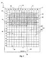
- FIG. 7 is a schematic representation of a third embodiment of page reference system of the present invention.
- FIG. 8 is a schematic representation of a fourth embodiment of page reference system of the present invention.
- FIG. 1 An exemplary embodiment of a page reference system 10 according to the present invention is illustrated in FIG. 1.
- page reference system 10 is printed onto a sheet 1 , or page, of media, such as paper, card stock, acetate (e.g., for use with an overhead projector), or the like, upon which a printing device, such as a printer, facsimile machine, copy machine, or the like, has printed various text and/or images.
- a printing device such as a printer, facsimile machine, copy machine, or the like
- One or more reference points 12 such as dots, lines, or symbols, form page reference system 10 .
- page reference system 10 may include indicia 18 that correspond to various reference points 12 , which may be referred to herein as “location indicia”, as well as one or more identifiers 20 (FIG. 2) for the type of printing device being used, which are also referred to herein as “device-identifying indicia”.
- sheet 1 includes an image 30 printed thereon in a so-called “portrait” orientation, with the short edges of sheet 1 comprising the top and bottom thereof and the long edges of sheet 1 comprising the sides thereof.
- Page reference system 10 which has also been printed onto sheet 1 , includes series of mutually parallel row lines 12 R and mutually parallel column lines 12 C that are oriented perpendicularly relative to row lines 12 R. Accordingly, row lines 12 R and column lines 12 C form a grid 14 , with boxes 16 of grid 14 being formed between adjacent pairs of row lines 12 R and column lines 12 C.
- FIG. 1 shows that row lines 12 R may be spaced equal distances apart from one another.
- Column lines 12 C may also be spaced equal distances apart from one another, either the same distance as that between adjacent row lines 12 R, as shown in FIG. 1, or a different distance than that between adjacent row lines 12 R.
- each box 16 of grid 14 is square in shape.
- the distance between adjacent column lines 12 C, as well as that between adjacent row lines 12 R, may be a known, calibrated length (e.g., 1 ⁇ 4′′, 1 ⁇ 2′′, 3 ⁇ 4′′, 1′′, 2′′, 3′′, etc.) so as to automatically provide a viewer with information about the dimensions of each box 16 , as well as the distance a particular defect may be located from each edge of sheet 1 .
- Indicia 18 of the depicted, exemplary page reference system 10 comprise letters that correspond to each column C of boxes 16 , which are positioned adjacent to their corresponding column C, and numbers that correspond to each row R of boxes 16 , which are positioned adjacent to their corresponding row R. While image 30 appears on sheet 1 in a “portrait” orientation, indicia 18 have been printed with sheet 1 traveling in a long edge-first direction through the printer and, thus, indicia 18 may appear on sheet 1 in a sideways orientation. The orientation of indicia 18 on sheet 1 may reflect the orientation of sheet 1 as it traveled through a problematic printing device for which a diagnosis is sought, as well as identify the leading edge of sheet 1 as it traveled through the problematic printing device.
- the sideways orientation of indicia 18 relative to the portrait-oriented image 30 indicates that sheet 1 traveled through the problematic printing device long edge-first. This is evident because the edge of sheet 1 that appears at the top thereof when indicia 18 are placed in a horizontal, reading orientation, in this case the right edge of sheet 1 , would have been the leading edge of sheet 1 .
- the orientation of indicia 18 , or additional indicia may also indicate which edge (i.e., the top short edge, the bottom short edge, the left long edge, or the right long edge) of sheet 1 traveled through the printer first.
- Image 30 comprises text 32 that appears in accordance with a user's desires, along with several defects, in this case a line 34 and several spots 36 that were not desired by the user of the printing device.
- a line 34 and several spots 36 that were not desired by the user of the printing device.
- the position of each defect such as a line 34 or spots 36 , may be readily identified by referring to each of the boxes 16 , which may be specified by column letter and row number or vice-versa, in which that defect occurs.
- FIG. 2 depicts another exemplary embodiment of page reference system 10 ′ incorporating teachings of the present invention.
- the depicted page reference system 10 ′ includes a sheet 1 , or page, of media onto which a printing device has printed various text and/or images.
- Reference points 12 ′ which have the appearance of cross hairs.
- Reference points 12 ′ are arranged in a grid-like fashion, with the horizontal lines of laterally adjacent reference points 12 ′ being aligned and the vertical lines of longitudinally adjacent reference points 12 ′ also in alignment.
- each reference point 12 ′ is spaced at equal distances from each vertically and horizontally adjacent reference point 12 ′, although the spacing between vertically adjacent reference points 12 ′ may be different from the spacing between horizontally adjacent reference points 12 ′.
- Page reference system 10 ′ may also include indicia 18 ′ that correspond to various reference points 12 ′. As shown in FIG. 2, indicia 18 ′ may comprise numerals positioned adjacent to corresponding reference points 12 ′. Indicia 18 ′ may be oriented in such a way as to indicate the path that was traveled by sheet 1 through the problematic printing device.
- An identifier 20 may be printed onto sheet 1 to identify the type of printing device being used to print text and/or images upon sheet 1 .
- a page reference system 10 , 10 ′ may be provided as a computer program in the form of software that may accompany or be a part of a driver program, which is commonly referred to simply as a “driver”, for a printer, facsimile machine, copy machine, or the like, as a separate printer diagnostic program, in the form of software, firmware, or hardware that may be executed by the processor of a printing device.
- a driver program which is commonly referred to simply as a “driver”
- a separate printer diagnostic program in the form of software, firmware, or hardware that may be executed by the processor of a printing device.
- page reference program Such a program is referred to herein as a “page reference program”.
- all or part of a page reference system 10 , 10 ′ of the present invention may be provided as a preprinted sheet that may or may not correspond to the type of printer for which diagnosis is desired.
- FIGS. 1 and 2 depict page reference systems 10 , 10 ′ that include rows and columns with substantially equal widths
- other configurations of page references systems which may include rows or columns of different widths, are also within the scope of the present invention.
- a page reference system 10 ′′ may include a single line 12 a ′′ or reference points 13 ′′ that are arranged in a single line 12 b ′′.
- the line 12 ′′ or reference points 13 ′′ of such an embodiment of page reference system could be positioned so as to align approximately with the position of a potentially problematic component of a printing device, such as a thermistor thereof.
- a printing defect such as a smudge 35
- a predetermined distance e.g., about one centimeter
- a page reference system 10 ′′′ incorporating teachings of the present invention may include adjacent columns or rows with boxes 16 a ′′′, 16 b ′′′, 16 c ′′′, etc. of different sizes, as shown in FIG. 8.
- the heights of boxes 16 a ′′′ may be about 30 mm
- boxes 16 b ′′′ of the next, adjacent column have heights of about 56 mm
- boxes 16 c ′′′ are 65 mm high.
- FIG. 3 an exemplary method for diagnosing the cause of a printing defect in a problematic printing device is illustrated.
- a page reference system 10 , 10 ′ (FIGS. 1 and 2) is provided to the problematic printing device along with a file, in the form of a text and/or images, to be printed.
- page reference system 10 , 10 ′, 10 ′′, 10 ′′′ may be provided to the problematic printing device in a number of different ways.
- a preprinted sheet 1 of a page reference system 10 , 10 ′, 10 ′′, 10 ′′′ may be placed in a sheet intake portion (e.g., a drawer, receptacle, etc.) of the problematic printing device.
- a page reference system 10 , 10 ′, 10 ′′, 10 ′′′ of the present invention may be provided to a processor of the problematic printing device
- data embodied in a carrier wave e.g, an electrical signal conveyed along a wire or cable, an electromagnetic signal carried along a fiber optic line, a wireless electromagnetic signal, etc.
- the page reference system data may be sent to the printer substantially concurrently with data that corresponds to a file (e.g., text and/or images) to be printed onto sheet 1 , which file is also referred to herein as a “selected file”.
- the processor of the problematic printer may print the appropriate images, including reference points 12 , 12 ′ and any indicia 18 , onto sheet 1 .
- Page reference system 10 , 10 ′, 10 ′′, 10 ′′′ may then be printed onto sheet 1 either as a watermark, as solid images, or as a combination thereof, and superimposed with a selected file.
- the manner in which page reference system 10 , 10 ′, 10 ′′, 10 ′′′ is printed may be predetermined, automatically determined, or set by a user of the problematic printer (e.g., by use of options provided in printer driver software or another page reference system 10 , 10 ′, 10 ′′, 10 ′′′-generating program).
- page reference system 10 , 10 ′, 10 ′′, 10 ′′′ is printed as a watermark, it may appear lighter than the printed images that correspond to the data of the selected file and may be printed without substantially altering the appearance of the selected file at locations where the selected file and page reference system 10 , 10 ′, 10 ′′, 10 ′′′ overlap one another.
- page reference system 10 , 10 ′, 10 ′′, 10 ′′′ and the selected file are printed as superimposed files
- either page reference system 10 , 10 ′, 10 ′′, 10 ′′′ or the selected file may take precedence in locations at which portions of page reference system 10 , 10 ′, 10 ′′, 10 ′′′ and the selected file overlap one another, with the printed elements of the file taking precedence in appearing on sheet 1 and masking “underlying” elements of the other of the selected file and page reference system 10 , 10 ′ at the overlapping locations.
- Page reference systems 10 , 10 ′, 10 ′′, 10 ′′′ that include combinations of watermark type elements and solid elements are also within the scope of the present invention.
- reference points 12 , 12 ′ could be printed more lightly (e.g., as a watermark) than the text or images are printed onto sheet 1 , while indicia 18 , 18 ′ may have a more visible, solid appearance.
- a page reference system according to the present invention such as page reference system 10 , 10 ′, 10 ′′, or 10 ′′′, may be provided to a problematic printer as a preprinted sheet, by way of the user of a problematic printer selecting an appropriate option on printer driver software, when the user of a problematic printer or a product support representative with access to the user's computer, as known in the art, causes a page reference system-generating program (i. e., software) on the user's computer to be executed, or by the user of a problematic printer causing the problematic printer to execute a program stored on the printer (e.g., in the form of firmware, programmed or programmable hardware, etc.).
- a page reference system-generating program i. e., software
- the diagnostic program may require the user or permit a product support representative with access thereto to select a file to be printed, at reference character 54 of FIG. 4, and to configure page reference system 10 , 10 ′, 10 ′′, 10 ′′′ (FIGS. 1, 2, 7 , and 8 ) to be printed onto a sheet 1 with the selected file, at reference character 56 of FIG. 4.
- the diagnostic program may then, at reference character 58 of FIG. 4, digitally “superimpose” the file to be printed and page reference system 10 , 10 ′, 10 ′′, 10 ′′′. This combined file may then be sent to the problematic printer, at reference character 60 of FIG. 4.
- a page reference system 10 , 10 ′, 10 ′′, 10 ′′′ may be generated by a page reference program that resides on a printing device 70 , such as in memory 73 a , firmware 73 b , or programmed or programmable hardware 73 c thereof.
- FIG. 5 schematically depicts a printing device 70 that includes or may be programmed to include a page reference program according to the present invention. The use of such a program is illustrated in the flow chart of FIG. 6.
- the page reference program may be retrieved and initiated by a processor 72 of printing device 70 , at reference character 62 of FIG. 6, by providing processor 72 of printing device 70 with an appropriate command.
- Such a command may be provided to processor 72 from a computer 80 in communication therewith (e.g., through a communication element 78 of printing device 70 ) or by entering a command directly into an input element 74 of printing device 70 , such as by depressing the depicted button.
- the page reference program may cause processor 72 to at least partially digitally superimpose the file to be printed and a page reference system 10 , 10 ′, as shown at reference character 64 of FIG. 6.
- the processor e.g., processor 72 in FIG. 5 of the problematic printing device (e.g., printing device 70 in FIG. 5) may cause the selected file to be printed onto sheet 1 (FIGS. 1 and 2) by a printing component (e.g., printing component 76 depicted in FIG. 5) of the problematic printing device, as known in the art.
- page reference system 10 , 10 ′ (FIGS. 1 and 2) is supplied to the problematic printer as data
- page reference system 10 , 10 ′ may be printed onto sheet 1 substantially simultaneously with the selected data or separately therefrom by causing sheet 1 to be reintroduced through the problematic printing device.
- page reference system 10 , 10 ′, 10 ′′, 10 ′′′ is printed onto a sheet 1 of transparent media, such as acetate
- page reference system 10 , 10 ′, 10 ′′, 10 ′′′ may be printed separately from printing, at reference character 42 , of another file and superimposed thereover to evaluate any printing defects.
- page reference system 10 , 10 ′, 10 ′′, 10 ′′′ may be separately printed onto a sheet 1 of paper or other opaque media, then subsequently used like a ruler relative to a sheet 1 on which a file has been printed and on which one or more printing defects occur.
- printing of page reference system 10 , 10 ′, 10 ′′, 10 ′′′ may be effected with the problematic printer or with another printing device.
- the user of the problematic printer evaluates the images printed onto sheet 1 and locates any defects, such as the lines 34 and spots 36 depicted in FIG. 1.
- the user may identify the location of each defect with respect to one or more reference points 12 , 12 ′ (FIGS. 1 and 2) and accompanying indicia 18 , 18 ′ of page reference system 10 , 10 ′, 10 ′′, 10 ′′′.
- the user of the problematic printer may then take remedial action on his or her own, preferably in reliance upon a corresponding trouble shooting guide associated with the particular model of printer being used.
- the reference grid file may itself include remedial instructions.
- a text string such as “Clean the thermistor if a linear smudge appears in column J.” could be printed somewhere on the page.
- descriptions of the defects and their respective locations on sheet 1 may then be communicated to a product support representative or other diagnostician, as indicated at reference character 46 of FIG. 3.
- these descriptions may be provided to the product support representative orally (e.g., over the telephone), by written description (e.g., by e-mail, text messaging, etc.), or visually (e.g., by electronic transmittal of a scanned file, by mail, etc.).
- the product support representative may then evaluate one or more of the defects, patterns of defects, and repetition of defects at reference character 48 of FIG. 3 and, based upon such evaluation, identify one or more possible causes of each type of defect, at reference character 50 of FIG. 3. Possible remedies for each type of printing defect, if available, may then be communicated to the user of the problematic printer, at reference character 52 of FIG. 3.
- lines 12 R of page reference system 10 may be positioned a uniform distance (e.g., about 30 mm) apart from one another that corresponds to a circumference of a roller of the defective printer.
- the occurrence of spots 36 at substantially equal distances from each line 12 R (e.g., 5 mm, 10 mm, 15 mm, etc.) of page reference system 10 may indicate that the roller was responsible for spots 36 . If, however, spots 36 appear at differing distances from each line 12 R (e.g., 5 mm from one grid line and 10 mm from the next grid line), it can be concluded that the roller is not responsible for the appearance of spots 36 .
Abstract
Description
- 1. Field of the Invention
- The present invention relates generally to methods and apparatus for providing points of reference for files that are printed on sheets of paper or other media. More specifically, the present invention relates to methods for using such points of reference in manually diagnosing the causes of printing defects that may occur as the files are printed onto the sheets.
- 2. Background of Related Art
- Typically, printing is effected by providing a digital file to a printing device, such as a printer, facsimile machine, copy machine, or the like. A file to be printed may be accompanied by a so-called “packet”, which may include identifiers for the source device and the intended recipient device, and instructions as to how the file is to be printed (e.g., the number of copies, the type of paper or other sheets of media to be used, the orientation in which printing is to be effected on such sheets, etc.). Upon receiving such a file, along with its accompanying packet, a processor of a printing device may “read” the digital file and cause a printing component of the printing device to print the appropriate images (e.g., text, lines, graphics, fills, etc.) onto one or more sheets of media.
- In addition to printing the desired text and/or other images, the printing component of a printing device may print other, undesirable elements onto one or more of the sheets of media. For example, spots, lines, streaks, bleeding, haloing, tenting (an undesired space between images or different elements of an image caused by the creation of a so-called “shadow” at the edge of a particular element of an image), trail-edge deletion and starvation, and other so-called “defects” or “imperfections” may appear on the one or more sheets upon which the desired images are printed.
- Many printing defects are often caused by the printing component of a printing device rather than by the processor thereof and may be remedied by a user of the printer, provided appropriate software is available to the user or the user has been given proper instructions.
- If the user of a printing device is unable to correct these defects by use of options that are available in the driver software for that printing device, he or she may contact a product support representative for help in remedying the printing defects. The user of the printing device may not, however, be able to adequately describe the locations, sizes, or types of defects that are occurring as a digital image is converted to a printed image by the printing device. Likewise, the user of the printing device may not understand or be able to quickly and clearly communicate to the product support representative whether or not the defect is the result of the image that is being printed or due to a malfunction of the printing device (e.g., repeating dots caused by a reel or fuser within the printing device).
- When a product support representative asks questions of the user of a printing device regarding the printing problems that are occurring, such as the type of problem, the direction in which sheets are fed through the printing device, the orientation of the image on the sheet, etc., it is not infrequent for the user of the printing device to guess or speculate regarding an answer if he or she is not sure of the precise answer.
- In other instances, the user of a printing device may provide a product support representative with a sample of the printing error (e.g., by mail, scanned and e-mailed image, etc.). Nonetheless, such a sample may lack information that the product support representative needs to properly respond to the printing problem at issue.
- Accordingly, it appears that there is a need for a system that provides accepted, common reference points by which a user of a printing device may communicate information to a product support representative, as well as a method for generating such common reference points during use of a printing device that is causing defects.
- The present invention includes a method for providing points of reference on a printed page, as well as a printed page including such points of reference, a system using such a printed page, and a process for resolving printing defects by use of such a printed page.
- Points of reference may be provided on a printed page in accordance with teachings of the present invention in a number of ways. By way of example, a software file comprising the reference points that correspond to a particular page orientation may be printed simultaneously with text and/or an image to be printed. As used herein, the term “image” applies to graphic images, as well as to lines, shapes, fills, and combinations thereof. The software file may be configured to form a so-called “watermark”, which is typically printed as a background to another printed image, or as a normal printed image to be superimposed relative to (i.e., over or under) another printed image.
- A printed page according to the present invention may include a printed image and one or more reference points. By way of example only, the page may include a line grid, along with column and row identifiers. Accordingly, a user of the printing device can readily identify the location of a particular defect with respect to one or more boxes of the grid by determining the column and row in which each such box is located. In addition, the user of the printing device may be able to supply information as to the particular location of a defect within one or more boxes, as well as the size of the defect relative to the box or boxes in which it is located and the orientation of the defect relative to the box or the grid.
- A user may cause a software file, which is also referred to herein as a “page reference program”, that encodes one or more points of reference that are to be printed to be supplied to a printing device (e.g., a printer, fax machine, copier, etc.) concurrently with the text and/or image to be printed. As an example of the manner in which a user of a printing device may cause reference points to be printed on a sheet along with an image, the user may select an option for printing such points of reference from a driver program for the problematic printing device. In another example, one or more desired text and/or image files may be printed simultaneously with reference points according to the present invention in the environment of a program that is specifically designed to cause such reference points to be printed. As another example, a product support representative may remotely access a user's computer or printer over the Internet or other telecommunications system and by way of a diagnostic program configured to provide such access and initiate printing of a test file and a particular set of reference points.
- Another embodiment of page reference program may be in the form of stored software, firmware, or programmed hardware on a printing device. This type of page reference program may be executed by a processor of the printing device by providing the processor with an appropriate command.
- When the points of reference are printed onto a sheet concurrently with an image, the orientations of one or more of the reference points may provide information about the orientation (e.g., feeding short edge first, long edge first, etc.) of the sheet as it passed through the printing device. In addition, or as another alternative, information identifying the type of printing device being used may be printed along with the points of reference. Such identifying information may be important since two devices may be referred to in a similar manner and possess only subtle differences.
- As an alternative to printing reference points concurrently with the printing of text and/or an image onto a sheet, the user of a printing device may be provided with sheets of paper or other media that include points of reference at particular locations thereon, which sheets are referred to herein as “diagnostic paper”. Optionally, such diagnostic paper may correspond to a particular type of printer and may include preprinted information thereon about the type of printing device to which the diagnostic paper corresponds. When the user is having problems with the printing device that he or she would like to discuss with a product support representative, one or more sheets of such diagnostic paper may be used with a problematic printing device to print a desired image onto the paper. The points of reference that appear on the paper may then be used, along with the printed image, as the basis for discussing the printing problem or problems with a product support representative.
- Once an image has been printed onto a sheet that also includes one or more points of reference according to the present invention, the user of a problematic printing device can discuss operation of the printing device and one or more printing defects with respect to the one or more points of reference. If the location indicia are also printed onto the sheet, the user may also describe the locations of printing defects with respect to such location indicia. Also, if such location indicia are printed onto the sheet, the user of a problematic printing device may explain the orientation of such location indicia to a product support representative, which explanation may provide the product support representative with more information pertinent to the cause or causes of the one or more printing defects that appear on the sheet. When the sheet includes information about the type of printing device being used, or device-identifying indicia, a user of the printing device may readily provide a product support representative with accurate information about the type of printing device having problems by referring to such identifying information.
- Other features and advantages of the present invention will become apparent to those of ordinary skill in the art through a consideration of the ensuing description, the accompanying drawings, and the appended claims.
- In the drawings, which illustrate exemplary embodiments of various aspects of the present invention:
- FIG. 1 is a schematic representation of a first embodiment of page reference system according to the present invention;
- FIG. 2 is a schematic representation of a second embodiment of page reference system according to the present invention;
- FIG. 3 is a flow chart depicting an exemplary process flow of a method of the present invention;
- FIG. 4 is a flow chart depicting an exemplary process flow for a computer-operated or workstation-operated diagnostic program incorporating teachings of the present invention;
- FIG. 5 schematically depicts a printing device that includes programming to effect a diagnostic method according to the present invention;
- FIG. 6 is a flow chart depicting an exemplary process flow for a printing device-operated diagnostic program according to the present invention;
- FIG. 7 is a schematic representation of a third embodiment of page reference system of the present invention; and
- FIG. 8 is a schematic representation of a fourth embodiment of page reference system of the present invention.
- An exemplary embodiment of a
page reference system 10 according to the present invention is illustrated in FIG. 1. As shown,page reference system 10 is printed onto asheet 1, or page, of media, such as paper, card stock, acetate (e.g., for use with an overhead projector), or the like, upon which a printing device, such as a printer, facsimile machine, copy machine, or the like, has printed various text and/or images. One ormore reference points 12, such as dots, lines, or symbols, formpage reference system 10. In addition,page reference system 10 may includeindicia 18 that correspond tovarious reference points 12, which may be referred to herein as “location indicia”, as well as one or more identifiers 20 (FIG. 2) for the type of printing device being used, which are also referred to herein as “device-identifying indicia”. - As depicted,
sheet 1 includes animage 30 printed thereon in a so-called “portrait” orientation, with the short edges ofsheet 1 comprising the top and bottom thereof and the long edges ofsheet 1 comprising the sides thereof.Page reference system 10, which has also been printed ontosheet 1, includes series of mutuallyparallel row lines 12R and mutuallyparallel column lines 12C that are oriented perpendicularly relative torow lines 12R. Accordingly,row lines 12R andcolumn lines 12C form agrid 14, withboxes 16 ofgrid 14 being formed between adjacent pairs ofrow lines 12R andcolumn lines 12C. FIG. 1 shows that rowlines 12R may be spaced equal distances apart from one another.Column lines 12C may also be spaced equal distances apart from one another, either the same distance as that betweenadjacent row lines 12R, as shown in FIG. 1, or a different distance than that betweenadjacent row lines 12R. Asrow lines 12R of thepage reference system 10 depicted in FIG. 1 are spaced apart from one another the same distance that column lines 12C are spaced apart from each other, eachbox 16 ofgrid 14 is square in shape. The distance betweenadjacent column lines 12C, as well as that betweenadjacent row lines 12R, may be a known, calibrated length (e.g., ¼″, ½″, ¾″, 1″, 2″, 3″, etc.) so as to automatically provide a viewer with information about the dimensions of eachbox 16, as well as the distance a particular defect may be located from each edge ofsheet 1. -
Indicia 18 of the depicted, exemplarypage reference system 10 comprise letters that correspond to each column C ofboxes 16, which are positioned adjacent to their corresponding column C, and numbers that correspond to each row R ofboxes 16, which are positioned adjacent to their corresponding row R. Whileimage 30 appears onsheet 1 in a “portrait” orientation,indicia 18 have been printed withsheet 1 traveling in a long edge-first direction through the printer and, thus, indicia 18 may appear onsheet 1 in a sideways orientation. The orientation ofindicia 18 onsheet 1 may reflect the orientation ofsheet 1 as it traveled through a problematic printing device for which a diagnosis is sought, as well as identify the leading edge ofsheet 1 as it traveled through the problematic printing device. In this case, the sideways orientation ofindicia 18 relative to the portrait-orientedimage 30 indicates thatsheet 1 traveled through the problematic printing device long edge-first. This is evident because the edge ofsheet 1 that appears at the top thereof whenindicia 18 are placed in a horizontal, reading orientation, in this case the right edge ofsheet 1, would have been the leading edge ofsheet 1. The orientation ofindicia 18, or additional indicia (not shown) may also indicate which edge (i.e., the top short edge, the bottom short edge, the left long edge, or the right long edge) ofsheet 1 traveled through the printer first. -
Image 30 comprisestext 32 that appears in accordance with a user's desires, along with several defects, in this case aline 34 andseveral spots 36 that were not desired by the user of the printing device. Asimage 30 andpage reference system 10 are superimposed, the position of each defect, such as aline 34 orspots 36, may be readily identified by referring to each of theboxes 16, which may be specified by column letter and row number or vice-versa, in which that defect occurs. - FIG. 2 depicts another exemplary embodiment of
page reference system 10′ incorporating teachings of the present invention. The depictedpage reference system 10′ includes asheet 1, or page, of media onto which a printing device has printed various text and/or images. Among the images printed onsheet 1 arereference points 12′, which have the appearance of cross hairs. Reference points 12′ are arranged in a grid-like fashion, with the horizontal lines of laterallyadjacent reference points 12′ being aligned and the vertical lines of longitudinallyadjacent reference points 12′ also in alignment. As depicted, eachreference point 12′ is spaced at equal distances from each vertically and horizontallyadjacent reference point 12′, although the spacing between verticallyadjacent reference points 12′ may be different from the spacing between horizontallyadjacent reference points 12′. -
Page reference system 10′ may also includeindicia 18′ that correspond tovarious reference points 12′. As shown in FIG. 2,indicia 18′ may comprise numerals positioned adjacent tocorresponding reference points 12′.Indicia 18′ may be oriented in such a way as to indicate the path that was traveled bysheet 1 through the problematic printing device. - An
identifier 20 may be printed ontosheet 1 to identify the type of printing device being used to print text and/or images uponsheet 1. - A
page reference system page reference system - While FIGS. 1 and 2 depict
page reference systems - As another alternative, and with reference to FIG. 7, a
page reference system 10″ incorporating teachings of the present invention may include asingle line 12 a″ orreference points 13″ that are arranged in asingle line 12 b″. By way of example only, theline 12″ orreference points 13″ of such an embodiment of page reference system could be positioned so as to align approximately with the position of a potentially problematic component of a printing device, such as a thermistor thereof. If a printing defect, such as asmudge 35, is roughly parallel to and within a predetermined distance (e.g., about one centimeter) of such aline 12 a″, 12 b″, a contaminated thermistor could be readily determined to be the cause of the printing defect. Of course, other defect-specific page reference systems are also within the scope of the present invention. - Also, a
page reference system 10′″ incorporating teachings of the present invention may include adjacent columns or rows withboxes 16 a′″, 16 b′″, 16 c′″, etc. of different sizes, as shown in FIG. 8. By way of example only, the heights ofboxes 16 a′″may be about 30 mm, whileboxes 16 b′″ of the next, adjacent column have heights of about 56 mm, andboxes 16 c′″ are 65 mm high. These different heights may correspond to dimensions of different components of a problematic printer, such as the circumferences of different rollers. - Turning now to the flow chart of FIG. 3, an exemplary method for diagnosing the cause of a printing defect in a problematic printing device is illustrated. At
reference character 40, apage reference system - Referring again to FIGS. 1, 2, 7, and 8
page reference system preprinted sheet 1 of apage reference system - As another example of the manner in which a
page reference system page reference system sheet 1. The page reference system data may be sent to the printer substantially concurrently with data that corresponds to a file (e.g., text and/or images) to be printed ontosheet 1, which file is also referred to herein as a “selected file”. - Upon receiving data corresponding to a file to be printed and the page reference system data, the processor of the problematic printer may print the appropriate images, including
reference points indicia 18, ontosheet 1.Page reference system sheet 1 either as a watermark, as solid images, or as a combination thereof, and superimposed with a selected file. The manner in whichpage reference system page reference system - If
page reference system page reference system - If, in the alternative,
page reference system page reference system page reference system sheet 1 and masking “underlying” elements of the other of the selected file andpage reference system -
Page reference systems reference points sheet 1, whileindicia - A page reference system according to the present invention, such as
page reference system - If the printed
page reference system reference character 54 of FIG. 4, and to configurepage reference system sheet 1 with the selected file, atreference character 56 of FIG. 4. The diagnostic program may then, atreference character 58 of FIG. 4, digitally “superimpose” the file to be printed andpage reference system reference character 60 of FIG. 4. - Alternatively, with additional reference to FIG. 5, a
page reference system printing device 70, such as inmemory 73 a,firmware 73 b, or programmed or programmable hardware 73 c thereof. FIG. 5 schematically depicts aprinting device 70 that includes or may be programmed to include a page reference program according to the present invention. The use of such a program is illustrated in the flow chart of FIG. 6. The page reference program may be retrieved and initiated by aprocessor 72 ofprinting device 70, atreference character 62 of FIG. 6, by providingprocessor 72 ofprinting device 70 with an appropriate command. Such a command may be provided toprocessor 72 from acomputer 80 in communication therewith (e.g., through acommunication element 78 of printing device 70) or by entering a command directly into aninput element 74 ofprinting device 70, such as by depressing the depicted button. Upon receipt of a packet that includes a file to be printed byprocessor 72, the page reference program may causeprocessor 72 to at least partially digitally superimpose the file to be printed and apage reference system reference character 64 of FIG. 6. - Returning reference to FIGS. 1 through 3, at
reference character 42 of FIG. 3, the processor (e.g.,processor 72 in FIG. 5) of the problematic printing device (e.g.,printing device 70 in FIG. 5) may cause the selected file to be printed onto sheet 1 (FIGS. 1 and 2) by a printing component (e.g.,printing component 76 depicted in FIG. 5) of the problematic printing device, as known in the art. Ifpage reference system page reference system sheet 1 substantially simultaneously with the selected data or separately therefrom by causingsheet 1 to be reintroduced through the problematic printing device. - Alternatively, if
page reference system sheet 1 of transparent media, such as acetate,page reference system reference character 42, of another file and superimposed thereover to evaluate any printing defects. As another alternative,page reference system sheet 1 of paper or other opaque media, then subsequently used like a ruler relative to asheet 1 on which a file has been printed and on which one or more printing defects occur. Of course, printing ofpage reference system - Next, at
reference character 44 of FIG. 3, the user of the problematic printer evaluates the images printed ontosheet 1 and locates any defects, such as thelines 34 andspots 36 depicted in FIG. 1. In addition, the user may identify the location of each defect with respect to one ormore reference points indicia page reference system - The user of the problematic printer may then take remedial action on his or her own, preferably in reliance upon a corresponding trouble shooting guide associated with the particular model of printer being used. Alternatively, the reference grid file may itself include remedial instructions. By way of example only, a text string, such as “Clean the thermistor if a linear smudge appears in column J.” could be printed somewhere on the page.
- Alternatively, descriptions of the defects and their respective locations on
sheet 1 may then be communicated to a product support representative or other diagnostician, as indicated atreference character 46 of FIG. 3. By way of example only, these descriptions may be provided to the product support representative orally (e.g., over the telephone), by written description (e.g., by e-mail, text messaging, etc.), or visually (e.g., by electronic transmittal of a scanned file, by mail, etc.). - The product support representative may then evaluate one or more of the defects, patterns of defects, and repetition of defects at
reference character 48 of FIG. 3 and, based upon such evaluation, identify one or more possible causes of each type of defect, atreference character 50 of FIG. 3. Possible remedies for each type of printing defect, if available, may then be communicated to the user of the problematic printer, atreference character 52 of FIG. 3. - By way of example only, and referring again to FIG. 1,
lines 12R ofpage reference system 10 may be positioned a uniform distance (e.g., about 30 mm) apart from one another that corresponds to a circumference of a roller of the defective printer. The occurrence ofspots 36 at substantially equal distances from eachline 12R (e.g., 5 mm, 10 mm, 15 mm, etc.) ofpage reference system 10 may indicate that the roller was responsible forspots 36. If, however, spots 36 appear at differing distances from eachline 12R (e.g., 5 mm from one grid line and 10 mm from the next grid line), it can be concluded that the roller is not responsible for the appearance ofspots 36. - Although the foregoing description contains many specifics, these should not be construed as limiting the scope of the present invention, but merely as providing illustrations of some exemplary embodiments. Similarly, other embodiments of the invention may be devised which do not depart from the spirit or scope of the present invention. Features from different embodiments may be employed in combination. Additions, deletions, and modifications to the invention, as disclosed herein, which fall within the meaning and scope of the claims are to be embraced thereby.
Claims (25)
Priority Applications (1)
| Application Number | Priority Date | Filing Date | Title |
|---|---|---|---|
| US10/119,650 US20030193684A1 (en) | 2002-04-10 | 2002-04-10 | Method and system for diagnosing printing defects |
Applications Claiming Priority (1)
| Application Number | Priority Date | Filing Date | Title |
|---|---|---|---|
| US10/119,650 US20030193684A1 (en) | 2002-04-10 | 2002-04-10 | Method and system for diagnosing printing defects |
Publications (1)
| Publication Number | Publication Date |
|---|---|
| US20030193684A1 true US20030193684A1 (en) | 2003-10-16 |
Family
ID=28789956
Family Applications (1)
| Application Number | Title | Priority Date | Filing Date |
|---|---|---|---|
| US10/119,650 Abandoned US20030193684A1 (en) | 2002-04-10 | 2002-04-10 | Method and system for diagnosing printing defects |
Country Status (1)
| Country | Link |
|---|---|
| US (1) | US20030193684A1 (en) |
Cited By (9)
| Publication number | Priority date | Publication date | Assignee | Title |
|---|---|---|---|---|
| US20030202200A1 (en) * | 2002-04-30 | 2003-10-30 | Terrill Jody Lee | Avoiding printing defects |
| US20040213435A1 (en) * | 2002-06-12 | 2004-10-28 | Seiko Epson Corporation | Method of evaluating image pattern output accuracy |
| US20050243354A1 (en) * | 2004-05-03 | 2005-11-03 | O'neill Kevin | Imaging device configuration pages |
| US20060096482A1 (en) * | 2004-11-08 | 2006-05-11 | Duke Dana K | Printed object and a print monitoring system for inspection of same |
| US20060238780A1 (en) * | 2005-04-20 | 2006-10-26 | Dennison Carl M | Validation of a print verification system |
| US10232247B2 (en) | 2015-10-19 | 2019-03-19 | Hydra Management Llc | Instant ticket redundancy via multi-chromatic indicia |
| US10252555B2 (en) | 2015-10-19 | 2019-04-09 | Hydra Management Llc | Instant ticket redundancy via multi-chromatic indicia |
| US10377162B2 (en) | 2015-10-19 | 2019-08-13 | Hydra Management Llc | Instant ticket redundancy via multi-chromatic indicia |
| US10603924B2 (en) | 2015-06-30 | 2020-03-31 | Hewlett-Packard Development Company, L.P. | Print quality evaluation |
Citations (18)
| Publication number | Priority date | Publication date | Assignee | Title |
|---|---|---|---|---|
| US4344713A (en) * | 1980-07-09 | 1982-08-17 | Sperry Corporation | Character overprinting method and apparatus in non-impact printers |
| US4857715A (en) * | 1988-04-01 | 1989-08-15 | National Computer Systems, Inc. | Overprint registration system for printing a customized survey form and scannable form therefor |
| US4887260A (en) * | 1987-02-17 | 1989-12-12 | Hewlett-Packard Company | X.25 Wide area network channel status display |
| US5689626A (en) * | 1995-04-17 | 1997-11-18 | Apple Computer, Inc. | System and method for linking a file to a document and selecting the file |
| US6005670A (en) * | 1998-12-28 | 1999-12-21 | Xerox Corporation | Efficient identification of predicted printer defects for anamorphic pre-compensation |
| US6014471A (en) * | 1996-09-08 | 2000-01-11 | Scitex Corporation | Apparatus and method for retouching a digital representation of a color image |
| US6226108B1 (en) * | 1995-11-10 | 2001-05-01 | Canon Kabushiki Kaisha | Image processing apparatus and method for reproducing high quality image in low-density portion |
| US20010039892A1 (en) * | 2000-05-11 | 2001-11-15 | Bobst S. A. | Device for processing printing defects detected in a printing machine |
| US20010052992A1 (en) * | 2000-06-15 | 2001-12-20 | Fuji Photo Film Co., Ltd. | Image correction apparatus |
| US6385560B1 (en) * | 1999-09-03 | 2002-05-07 | Xerox Corporation | Diagnosis of repetitive quality faults |
| US20020113998A1 (en) * | 2001-02-19 | 2002-08-22 | Osamu Fujinawa | Print system |
| US6449385B1 (en) * | 1995-05-04 | 2002-09-10 | Heidelberger Druckmaschinen Ag | Device for image inspection |
| US6522430B1 (en) * | 1999-11-29 | 2003-02-18 | Xerox Corporation | Quantification of motion quality effect on image quality |
| US6647885B2 (en) * | 2001-03-29 | 2003-11-18 | Tomoegawa Paper Co., Ltd. | Marking system, marking method and marking apparatus |
| US6665425B1 (en) * | 1999-12-16 | 2003-12-16 | Xerox Corporation | Systems and methods for automated image quality based diagnostics and remediation of document processing systems |
| US6665424B1 (en) * | 1998-09-07 | 2003-12-16 | De La Rue Giori S.A. | Automatic inspection of print quality using an elastic model |
| US6894794B1 (en) * | 1999-06-24 | 2005-05-17 | Eastman Kodak Company | Method and apparatus for making a print having an invisible coordinate system |
| US7102769B2 (en) * | 2001-03-15 | 2006-09-05 | Hewlett-Packard Development Company, L.P. | Dynamic management and transmissions of error notification and configuration data for printing and paper handling devices |
-
2002
- 2002-04-10 US US10/119,650 patent/US20030193684A1/en not_active Abandoned
Patent Citations (18)
| Publication number | Priority date | Publication date | Assignee | Title |
|---|---|---|---|---|
| US4344713A (en) * | 1980-07-09 | 1982-08-17 | Sperry Corporation | Character overprinting method and apparatus in non-impact printers |
| US4887260A (en) * | 1987-02-17 | 1989-12-12 | Hewlett-Packard Company | X.25 Wide area network channel status display |
| US4857715A (en) * | 1988-04-01 | 1989-08-15 | National Computer Systems, Inc. | Overprint registration system for printing a customized survey form and scannable form therefor |
| US5689626A (en) * | 1995-04-17 | 1997-11-18 | Apple Computer, Inc. | System and method for linking a file to a document and selecting the file |
| US6449385B1 (en) * | 1995-05-04 | 2002-09-10 | Heidelberger Druckmaschinen Ag | Device for image inspection |
| US6226108B1 (en) * | 1995-11-10 | 2001-05-01 | Canon Kabushiki Kaisha | Image processing apparatus and method for reproducing high quality image in low-density portion |
| US6014471A (en) * | 1996-09-08 | 2000-01-11 | Scitex Corporation | Apparatus and method for retouching a digital representation of a color image |
| US6665424B1 (en) * | 1998-09-07 | 2003-12-16 | De La Rue Giori S.A. | Automatic inspection of print quality using an elastic model |
| US6005670A (en) * | 1998-12-28 | 1999-12-21 | Xerox Corporation | Efficient identification of predicted printer defects for anamorphic pre-compensation |
| US6894794B1 (en) * | 1999-06-24 | 2005-05-17 | Eastman Kodak Company | Method and apparatus for making a print having an invisible coordinate system |
| US6385560B1 (en) * | 1999-09-03 | 2002-05-07 | Xerox Corporation | Diagnosis of repetitive quality faults |
| US6522430B1 (en) * | 1999-11-29 | 2003-02-18 | Xerox Corporation | Quantification of motion quality effect on image quality |
| US6665425B1 (en) * | 1999-12-16 | 2003-12-16 | Xerox Corporation | Systems and methods for automated image quality based diagnostics and remediation of document processing systems |
| US20010039892A1 (en) * | 2000-05-11 | 2001-11-15 | Bobst S. A. | Device for processing printing defects detected in a printing machine |
| US20010052992A1 (en) * | 2000-06-15 | 2001-12-20 | Fuji Photo Film Co., Ltd. | Image correction apparatus |
| US20020113998A1 (en) * | 2001-02-19 | 2002-08-22 | Osamu Fujinawa | Print system |
| US7102769B2 (en) * | 2001-03-15 | 2006-09-05 | Hewlett-Packard Development Company, L.P. | Dynamic management and transmissions of error notification and configuration data for printing and paper handling devices |
| US6647885B2 (en) * | 2001-03-29 | 2003-11-18 | Tomoegawa Paper Co., Ltd. | Marking system, marking method and marking apparatus |
Cited By (17)
| Publication number | Priority date | Publication date | Assignee | Title |
|---|---|---|---|---|
| US20030202200A1 (en) * | 2002-04-30 | 2003-10-30 | Terrill Jody Lee | Avoiding printing defects |
| US7054017B2 (en) * | 2002-04-30 | 2006-05-30 | Hewlett-Packard Development, L.P. | Avoiding printing defects |
| US7388687B2 (en) * | 2002-06-12 | 2008-06-17 | Seiko Epson Corporation | Method of evaluating image pattern output accuracy |
| US20040213435A1 (en) * | 2002-06-12 | 2004-10-28 | Seiko Epson Corporation | Method of evaluating image pattern output accuracy |
| US20050243354A1 (en) * | 2004-05-03 | 2005-11-03 | O'neill Kevin | Imaging device configuration pages |
| US7443520B2 (en) | 2004-05-03 | 2008-10-28 | Hewlett-Packard Development Company, L.P. | Imaging device configuration pages |
| US7665400B2 (en) * | 2004-11-08 | 2010-02-23 | Scientific Games International, Inc. | Print monitoring system and method |
| US20060096482A1 (en) * | 2004-11-08 | 2006-05-11 | Duke Dana K | Printed object and a print monitoring system for inspection of same |
| US20060238780A1 (en) * | 2005-04-20 | 2006-10-26 | Dennison Carl M | Validation of a print verification system |
| US8472073B2 (en) | 2005-04-20 | 2013-06-25 | Ricoh Production Print Solutions LLC | Validation of a print verification system |
| US10603924B2 (en) | 2015-06-30 | 2020-03-31 | Hewlett-Packard Development Company, L.P. | Print quality evaluation |
| US10232247B2 (en) | 2015-10-19 | 2019-03-19 | Hydra Management Llc | Instant ticket redundancy via multi-chromatic indicia |
| US10252555B2 (en) | 2015-10-19 | 2019-04-09 | Hydra Management Llc | Instant ticket redundancy via multi-chromatic indicia |
| US10377162B2 (en) | 2015-10-19 | 2019-08-13 | Hydra Management Llc | Instant ticket redundancy via multi-chromatic indicia |
| US10752035B2 (en) | 2015-10-19 | 2020-08-25 | Hydragraphix Llc | Instant ticket redundancy via multi-chromatic indicia |
| US11203218B2 (en) | 2015-10-19 | 2021-12-21 | Hydragraphix, LLC | Instant ticket redundancy via multi-chromatic indicia |
| US11707942B2 (en) | 2015-10-19 | 2023-07-25 | Hydragraphix Llc | Instant ticket redundancy via multi-chromatic indicia |
Similar Documents
| Publication | Publication Date | Title |
|---|---|---|
| US7420719B2 (en) | Skew correction | |
| US5347302A (en) | Method for MICR encoding of checks using laser printers and confirmation of MICR positioning | |
| US10545844B2 (en) | Print verification system that reports defective printheads | |
| EP1320251B1 (en) | Semi-automatic image registration control for a digital copier | |
| JP4853050B2 (en) | Print management apparatus, program, and method | |
| CN101086698B (en) | Print control device and print control method | |
| US8159717B2 (en) | Image processing apparatus | |
| US10353652B2 (en) | Dynamic imposition identifier for items cut from sheets | |
| JP2007241413A (en) | Page error inspection device and page error inspection method | |
| JP2022184992A (en) | Image inspection device, image inspection program, image inspection system, and image inspection method | |
| US20030193684A1 (en) | Method and system for diagnosing printing defects | |
| JP6256530B2 (en) | Special processing indicator for print verification system | |
| US8422067B2 (en) | Image forming apparatus and method utilizing see-through prevention patterns to increase transillumination document security | |
| JP2020163804A5 (en) | ||
| JP4626151B2 (en) | Printing inspection apparatus and method | |
| US20190037091A1 (en) | Print management system, print management method, and storage medium | |
| JP4517651B2 (en) | Image forming apparatus abnormality detection device, abnormality detection method, and abnormality detection program | |
| US6608932B1 (en) | Outline font for analytical assessment of printed text quality | |
| JP4957261B2 (en) | Variable printing inspection method | |
| JPH04248761A (en) | Method of recovering trouble of scanner | |
| US20100080574A1 (en) | Printing device with sensor for output tray | |
| US8964192B2 (en) | Print verification database mechanism | |
| US20080198416A1 (en) | Ordered stock jam recovery | |
| US20080179391A1 (en) | Method for monitoring preparation of items to be mailed | |
| US8867048B2 (en) | Delayed review of scanned documents using unique identification marking on scanned documents |
Legal Events
| Date | Code | Title | Description |
|---|---|---|---|
| AS | Assignment |
Owner name: HEWLETT-PACKARD COMPANY, COLORADO Free format text: ASSIGNMENT OF ASSIGNORS INTEREST;ASSIGNORS:KENDALL, DAVID R.;BARRETT, TONY;REEL/FRAME:013031/0653 Effective date: 20020408 |
|
| AS | Assignment |
Owner name: HEWLETT-PACKARD DEVELOPMENT COMPANY, L.P., COLORAD Free format text: ASSIGNMENT OF ASSIGNORS INTEREST;ASSIGNOR:HEWLETT-PACKARD COMPANY;REEL/FRAME:013776/0928 Effective date: 20030131 Owner name: HEWLETT-PACKARD DEVELOPMENT COMPANY, L.P.,COLORADO Free format text: ASSIGNMENT OF ASSIGNORS INTEREST;ASSIGNOR:HEWLETT-PACKARD COMPANY;REEL/FRAME:013776/0928 Effective date: 20030131 |
|
| STCB | Information on status: application discontinuation |
Free format text: ABANDONED -- FAILURE TO RESPOND TO AN OFFICE ACTION |