US20030193479A1 - Optical system for inputting pointer and character data into electronic equipment - Google Patents
Optical system for inputting pointer and character data into electronic equipment Download PDFInfo
- Publication number
- US20030193479A1 US20030193479A1 US10/430,820 US43082003A US2003193479A1 US 20030193479 A1 US20030193479 A1 US 20030193479A1 US 43082003 A US43082003 A US 43082003A US 2003193479 A1 US2003193479 A1 US 2003193479A1
- Authority
- US
- United States
- Prior art keywords
- light
- input device
- operator
- optical
- data
- Prior art date
- Legal status (The legal status is an assumption and is not a legal conclusion. Google has not performed a legal analysis and makes no representation as to the accuracy of the status listed.)
- Granted
Links
Images


Classifications
-
- G—PHYSICS
- G06—COMPUTING; CALCULATING OR COUNTING
- G06F—ELECTRIC DIGITAL DATA PROCESSING
- G06F3/00—Input arrangements for transferring data to be processed into a form capable of being handled by the computer; Output arrangements for transferring data from processing unit to output unit, e.g. interface arrangements
- G06F3/01—Input arrangements or combined input and output arrangements for interaction between user and computer
- G06F3/03—Arrangements for converting the position or the displacement of a member into a coded form
- G06F3/041—Digitisers, e.g. for touch screens or touch pads, characterised by the transducing means
- G06F3/042—Digitisers, e.g. for touch screens or touch pads, characterised by the transducing means by opto-electronic means
- G06F3/0421—Digitisers, e.g. for touch screens or touch pads, characterised by the transducing means by opto-electronic means by interrupting or reflecting a light beam, e.g. optical touch-screen
Definitions
- the present invention relates generally to data input devices and, more particularly, to data input devices adapted for use with portable communications and computing equipment.
- miniaturized communications and computing equipment One problem associated with miniaturized communications and computing equipment is having a convenient way to input data, such as character and pointing device data, into such equipment.
- data such as character and pointing device data
- Early miniaturized computing equipment typical of the 1990s, included a miniaturized keyboard that was scaled to fit the desired sized of the computing equipment. Typing a few words using such systems is quite laborious because the operator's fingers are typically too large to use the device as a traditional keyboard.
- Portable communication equipment typically include a conventional 12-button keypad to input data. It is extremely difficult to use this set-up to enter non-numerical data.
- the data input device of the present invention optically interfaces with an operator to detect the position of objects within a particular input zone, e.g., an area defined as a “virtual keyboard” in which the operator may interact to enter character data into associated computing equipment.
- the objects are the operator's fingers placed within the input zone.
- each character data corresponds to a unique arrangement and position of the objects within the input zone.
- the relative motion of the operator's fingers defines the input area.
- the input device includes a source of optical sensor light illuminating the input zone with sensor light.
- the source of optical sensor light may be ambient light surrounding the operator or a light emitting device adapted to emit light in a direction toward the operator's fingers.
- the source of optical light covers the input zone.
- the sensor light reflects off the objects in a direction generally toward the input device.
- the data input device also includes an optical detector arranged to receive the reflected sensor light as a reflected light pattern representing the relative position of the operator's fingers within the input zone.
- the optical detector converts the reflected light pattern to an electrical signal representing the particular character data desired to be entered by the operator.
- a microprocessor then receives the electrical signal and correlates the electrical signal to character or position/motion data.
- an image generator is used to project an optical image that represents character data, e.g., an image of a real keyboard.
- the image generator may be formed by an optical element, such as a stencil, mask, holographic element, mirror array, or other suitable device known in the art of image projection, designed to allow light to pass through portions of the optical element and a light generator positioned to emit visible light through the portions of the optical element, whereby the light passed through the optical element forms the optical image.
- the present invention also includes a novel method to enter character data into communications or computing equipment based on the position of objects within an input zone, e.g., an operator's fingers on a virtual keyboard.
- the position of the objects within the input zone uniquely corresponds to particular character data.
- a reference position is established to associate an initial position of the objects within the input zone and to associate a plurality of positions of the objects within the input zone to unique character data.
- a source of optical sensor light is provided to illuminate the input zone such that the sensor light reflects off the objects. The reflected sensor light is then received as a reflected light pattern representing the position of the objects within the input zone. The reflected light pattern is converted to an electrical signal that is then correlated to the unique selection of character data, which may then be input into the electronic equipment.
- FIG. 1 is a diagrammatic representation of a data input device in accordance with a preferred embodiment of the present invention
- FIG. 2 is a diagram illustrating the principal components of a keyboard image generator used in the present invention
- FIG. 3 is a diagram illustrating a stencil used to form an image of a keyboard
- FIG. 4 is a diagram illustrating the principal components and operation of an optical sensor light source used in the present invention.
- FIG. 5 is a diagram illustrating the principal components and operation of optical sensor receiving unit used in the present invention.
- FIG. 6 is an illustration of a reflected light pattern received by the optical sensor receiving unit of FIG. 5;
- FIG. 7 is an illustration of an electrical signal generated from the light pattern of FIG. 6;
- FIG. 8 is a side view of a data input device in accordance with one embodiment of the present invention.
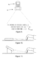
- FIG. 9 is an illustration depicting the data input device as a component of a conventional cellular telephone
- FIGS. 10 and 11 illustrate two side views of the data input device projecting and receiving light rays to and from an operator's fingers
- FIG. 12 is a flowchart illustrating the principal steps of a method to input character data in accordance with the present invention.
- FIG. 13 is a flowchart illustrating the principal steps of a method to input pointing device data in accordance with the present invention.
- FIG. 1 illustrates a preferred embodiment of the virtual data input device 10 of the present invention.
- the virtual data input device 10 may incorporate four primary elements including an image generator 20 , an optical sensor light source 40 , an optical sensor receiving unit 50 , and a microprocessor 60 , which controls overall system operation.
- the virtual data input device 10 optically interfaces with an operator desiring to enter characters, position, or other forms of data into equipment 70 such as any form of communications or computing equipment.
- This data may include any character or function typically incorporated into a conventional keyboard, including alphanumerics, symbols, function keys, operational keys (e.g., Tab and Enter) and Hot Keys.
- the characters and the like used by the operator to input this data may be displayed on a virtual keyboard 80 , which may take one of many forms as described below.
- a virtual keyboard 80 may take one of many forms as described below.
- the virtual data input device 10 of the present invention is particularly adapted for use with portable communications and computing equipment, including, for example, cellular telephones, Internet-ready cellular telephones, personal digital assistants, and the like, the virtual data input device 10 may also be suited for use with virtually any form of communications or computing equipment requiring entry of characters, pointing device data, and/or other forms of data, including standard desktop computers.
- the equipment 70 may include and/or interface with other forms of input and output devices, including display monitors, conventional keyboards, a pointing device (e.g., a mouse device), tablets, disk drives, infrared devices, and the like.
- the virtual data input device 10 is adapted to discriminate the position and motion of objects, e.g., the operator's fingers, and to generate character and position/motion information from such position and motion, all as described herein.
- FIG. 2 illustrates an image generator 20 in accordance with one embodiment of the present invention.
- the image generator 20 is designed to project an optical image of an input device, for example, a conventional QWERTY keyboard, onto any surface available to the operator, such as a table top, a desktop, a laptop, the ground, or a piece of paper.
- the image generator 20 includes a light generator 22 , an optical deflection device 30 , such as a stencil, and various lenses.
- the light generator 22 may be a diode laser, a gas laser, or other type of laser, a traditional incandescent light bulb or a florescent light bulb, a light emitting diode (LED), or other suitable device capable of producing visible light.
- the light generator 22 is low power and compact in design so that it may be incorporated into small communications and computing equipment such as cellular telephones and hand-held personal digital assistants.
- the light generator 22 delivers a visible light beam 24 to a collimating lens 26 .
- the collimating lens 26 diverges the light beam 24 and emits collimated rays 28 of light having an increased cross-sectional area. Rays 28 are then projected through a deflective optical element 30 and through lens 32 .
- Lens 32 expands the rays 28 to project an image, such as of a full size keyboard, at a suitable distance from the input device 10 and preferably adjacent an operator.
- the image generator 20 may be designed to project light through the deflective optical element 30 at a particular distance without the use of lens 32 .
- a diverging image beam 34 is produced that projects an image, such as an image 80 of a conventional keyboard, onto any surface.
- the image 80 is typically formed from a plurality of discrete sub-images 82 , that may represent, for example, particular keys on a conventional keyboard.
- the image 80 generally defines an input zone, i.e., the two-dimensional area within which the virtual data input device 10 will detect the position of the operator's fingers and correlate such position to unique character data.
- Each of the discrete sub-images 82 may then be selected by the operator for input into the equipment 70 based upon a unique position of objects within the input zone, e.g., a particular arrangement of fingers on the “virtual keyboard.”
- the light generator 22 may include features to control the brightness, contrast and focal length of image 80 .
- collimating lens 26 and/or lens 32 may be adjustable to allow the operator to control the position and focus of the projected image 80 .
- FIG. 3 illustrates a deflective optical element 30 in the form of a stencil that may be used to form an image of a keyboard.
- the deflective optical element 30 may also be formed by a mask, holographic element, mirror array, or other suitable device known in the art of image projection.
- the art of manufacturing deflective optical elements is well known in the image projection industry and, more particularly, the art of making stencils and masks is also well known in the semiconductor and electronics industry. As is known, features on the order of tenths of a micron can easily be formed on deflective optical elements, thus permitting the deflective optical element 30 to be installed into small components.
- the deflective optical element 30 may be formed from an opaque material having portions of the material representing the keyboard or other image removed to allow light therethrough. While the deflective optical element 30 depicted in FIG. 3 shows a simple QWERTY keyboard, those skilled in the art will recognize that the deflective optical element 30 could be adapted to allow the projection of virtually any form of image.
- the image projected by the image generator 20 is used to both align the operator with the virtual data input device 10 and to define the potential character data.
- FIG. 4 illustrates the components of one embodiment used in and the operation of the optical sensor light source 40 .
- the light source 40 is used in conjunction with the optical sensor receiving unit 50 to sense and discriminate the position and motion of the operator's fingers and to generate a signal representing data (i.e., alphanumeric characters) information from such position and motion information.
- the light source 40 includes a fight emitting device 42 , for example, a diode laser producing a light beam 44 that is projected through a lens 46 to form a sheet of light 48 that is directed outwardly and in the general direction of the operator's fingers.
- the light emitting device 42 produces light having a different wavelength than the light produced by the light generator 22 of the image generator 20 , and generates non-visible light to prevent interference with the image of the keyboard projected by the image generator 20 and to prevent the operator from being distracted.
- the light source 40 is preferably arranged to cover the entire input zone (i.e., the projected image 80 ).
- each reflected light ray 58 along the length of the light sensing device 52 represents the position of the “key” in the virtual image 80 that is depressed by the operator.
- the intensity (strength) of the signal received by the light sensing device 52 represents the distance from the point of reflection (i.e., the operator's finger(s)).
- the light sensing device 52 then converts this light pattern (comprising both position and intensity) to an electrical signal as shown in FIG. 7.
- this light pattern may then be used to determine which key was selected by the operator.
- the optical sensor receiving unit 50 may incorporate features to limit the wavelength of light detected by the light sensing device 52 .
- the light sensing device 52 may be designed to detect only the wavelength of light emitted by the light emitting device 42 .
- the receiving unit 50 may include a light filter 56 to eliminate light of other wavelengths.
- the light sensing device 52 may be tuned to be wavelength sensitive or selective and designed for the particular wavelength of light emitted by the light emitting device 42 .
- the optical sensor receiving unit 50 requires a source of optical sensor light, which is described above as the light source 40 .
- the virtual data input device 10 may rely upon ambient light existing in the operator's surroundings as the source of optical sensor light to be reflected off of the operator's fingers and detected by the light sensing device 52 .
- This embodiment which eliminates the need for the components illustrated in FIG. 4, is preferably used where sufficient ambient light exists, such as an office environment having florescent lighting.
- the optical sensor receiving unit 50 transmits the electric signal that it generates to a microprocessor 60 , which may be included within the virtual data input device 10 .
- the optical sensor receiving unit 50 may send the electrical signal to a microprocessor 60 of the equipment 70 such that the signals may be interpreted and appropriate data input into the equipment 70 .
- the microprocessor 60 interprets the signal from the optical sensor receiving unit 50 that is then delivered to and recognized by communications and computing equipment 50 .
- the microprocessor 60 preferably includes an algorithm to determine which of the character data is selected.
- the microprocessor 60 may include a stored database of character data signals and then compare the received electrical signals to the signals stored in the database to correlate the received signals to character data. It may be preferred for the operator to first “teach” the system the unique position and/or motion of his/her fingers for a given character. This information may be stored in a database for reference during operation.
- the step of reading the operator's finger positions may be accomplished in a variety of ways.
- the electrical signal generated by the optical sensor receiving unit 50 and transmitted to microprocessor 60 may be substantially continuously read (e.g., every tenth, hundredth, or thousandth of a second) by microprocessor 60 and a character determined after the signal changes.
- the signal from the optical sensor receiving unit 50 remains constant and no character data would be transmitted to the equipment 70 . If the operator desires to input the letter “j” the right index finger positioned on that letter would be raised and then repositioned on the “j”.
- the microprocessor 60 After the motion is complete, the microprocessor 60 would detect a change in the signal from the optical sensor receiving unit 50 , compare the new signal to the previous signal and a look-up compiled database, and correctly read the newly inputted character. If the new signal does not match any signal stored in the database, no data or character is input during that particular cycle.
- FIG. 8 illustrates a side view of one embodiment of the virtual data input device 10 of the present invention.
- optical images or light emitted from or received by the device 10 include the image projecting the virtual keyboard, the optical sensing light, and the reflected light.
- FIG. 9 illustrates the virtual data input device 10 included as a component of a conventional cellular telephone 70 , projecting an image of a conventional keyboard 80 , which may be used to input alphanumeric data into the cellular telephone for use, for example, when the telephone 70 is used to wirelessly access the Internet.
- FIGS. 10 and 11 illustrate two side views of the device 10 showing the sensor light being emitted from the sensor light source 40 of the virtual data input device 10 and a portion of the emitted light being reflected off an operator's fingers and back to the sensor light detecting device 50 .
- FIG. 11 shows another embodiment in which the equipment 70 includes collapsible legs or stands to increase the angle between the light rays and the projection surface.
- FIG. 12 representatively illustrates a method of determining an object's position in accordance with the principles of the present invention.
- an image is projected in a convenient position for the operator.
- the operator generally must align his/her fingers with the image to establish a reference position within an input zone formed by the projected image.
- the plurality of different positions of the operator's fingers within the input zone must be associated with unique character data selections.
- the method begins at step 91 , in which the input device 10 continuously projects an image, e.g., an image of a conventional QWERTY keyboard.
- step 92 the operator aligns himself/herself with the projected image to establish a reference position.
- step 93 the input device 10 continuously illuminates the input zone with sensor light and, in step 94 , the device 10 continuously receives reflected light signals.
- the method then proceeds into a loop in which the device waits a period of time, e.g., between 10 and 2000 milliseconds (step 95 ) converts the received reflected light signal to an electrical signal (step 96 ) and then compares the converted electrical signal to the electrical signal detected and computed on the previous cycle (step 97 ). If the electrical signal is unchanged, the method returns to step 95 to delay for a short period of time before converting another light pattern. If the electrical signal is changed, the device determines, in step 98 , if the converted electrical signal matches a signal in the stored character database.
- a period of time e.g., between 10 and 2000 milliseconds
- step 99 the device then determines if the electrical signal matches a “home key” signal in the character database (defined as, e.g., ASDF-JKL;). If the converted electrical signal matches a “home key,” the device then determines if the identical electrical signal was taken as an input the previous cycle (step 100 ) and, if not, the device identifies the difference from the previous signal (step 101 ) and associates the difference with a particular character (step 102 ).
- a “home key” signal in the character database defined as, e.g., ASDF-JKL;
- step 103 proceeds with step 103 (after either associating the difference in the signal to a particular character from steps 101 and 102 , or determining that the signal matches a character in the database, but not a “home key” signal from steps 98 and 99 ) to accept the new character data.
- the new character data is then transmitted into the associated equipment (step 104 ) and, possibly, displayed on the display screen of the equipment ( 105 ). The method then proceeds back to step 95 for the next cycle.
- FIG. 13 illustrates a method using the virtual data input device 10 configured as a pointing device.
- the input device 10 is typically used to detect the position and motion of one of the operator's fingers moving across an input zone, e.g., a table or desk top.
- step 111 the input device 10 continuously projects an image, e.g., an image of a defined area for data input (e.g., a box, similar to a mouse pad).
- step 112 the operator aligns himself/herself with the projected image to establish a reference position.
- step 113 the input device 10 continuously illuminates the input zone with sensor light and, in step 114 , the device 10 continuously receives reflected light signals.
- the method then proceeds into a loop in which the device waits a period of time, e.g., between 10 and 2000 milliseconds (step 115 ) converts the received reflected light signal to an electrical signal (step 116 ) and then compares the converted electrical signal to the electrical signal detected and computed on the previous cycle (step 117 ). If the electrical signal is unchanged, the method returns to step 115 to delay for a short period of time before converting another light pattern. If the electrical signal is changed, the device determines, in step 118 , if the signal intensity changed and, if so, adjusts the up/down position of the pointing device (step 119 ). In step 120 , the device determines if the signal shifted and, if so, adjusts the left/right position of the pointing device (step 121 ). The updated pointer location may then be displayed on the display screen associated with the equipment in step 122 .
- a period of time e.g., between 10 and 2000 milliseconds
- a microprocessor may be used to execute an algorithm to determine which of a plurality of selection options (e.g., keys) is selected. For example, the microprocessor may compare the electrical signal to a stored database of signals representing unique character data selections. Alternatively, the microprocessor may compare the electrical signal to the previous electrical signal to relate the position of a pointing device on a display screen.
- a plurality of selection options e.g., keys
- the microprocessor may compare the electrical signal to a stored database of signals representing unique character data selections.
- the microprocessor may compare the electrical signal to the previous electrical signal to relate the position of a pointing device on a display screen.
- a projected image is solely for the operator's benefit. Just as many people can readily type on a keyboard without looking down to “hunt and peck” for keys, one may use the virtual data input device without the use of the projected image. It is preferred that there is a mechanism to align the operator's fingers to the virtual data input device 10 .
- Alternatives to the projected image include a simple sheet of paper that is located at a predetermined distance and position from the equipment (e.g., the equipment is rested on a spot marked on the paper). However, since the system is ultimately comparing the relative position of the operator's finger(s), there is an acceptable range of space for the operator to place his/her fingers and, therefore, the alignment of the device 10 is not a necessity.
- the virtual data input device 10 may include the ability to “learn” additional keystrokes.
- the operator may assign certain finger positions to a character or set of characters similar to a macro in popular word processing and spreadsheet software programs.
- the system may incorporate a “Hot Key” that allows the operator to switch between modes (e.g., from keyboard to mouse) by simply moving his/her fingers to a predetermined position.
- the principles of the present invention may be used as a character input device for various forms of portable communications and computer equipment, including cell phones, Internet-ready cell phones, palm-size computers, personal computers, laptop computers, notebook computers, personal digital assistants, and the like.
- the invention may also be used to input character data into portable hybrid communications and computing equipment such as palm-size computer telephones, standard desktop computers, hand-held data receiving or entry devices, GPS receivers, inventory management devices, and portable computing equipment integrated with automobiles, aircraft and the like.
- the virtual data input device may be used to detect the position of other forms of input means beyond an operator's fingers, such as a writing stylus or a computer mouse.
- the optical sensor light source 40 and the optical sensor receiving unit 50 may be configured to detect the position of an operator's fingers or other objects on a computer display screen.
- the features of the present invention can allow the virtual data input device to act as a form of touch sensitive screen.
Abstract
Description
- The present invention relates generally to data input devices and, more particularly, to data input devices adapted for use with portable communications and computing equipment.
- Demand for compact communications and computing equipment has increased dramatically over the last decade. Computers that can be held in the palm of your hand and wireless phones that fit in a shirt pocket are two examples of popular miniaturized machines. More recently, demand for wireless e-mail and Internet access has begun to soar, with experts projecting future demand to rise at unprecedented rates.
- One problem associated with miniaturized communications and computing equipment is having a convenient way to input data, such as character and pointing device data, into such equipment. Early miniaturized computing equipment, typical of the 1990s, included a miniaturized keyboard that was scaled to fit the desired sized of the computing equipment. Typing a few words using such systems is quite laborious because the operator's fingers are typically too large to use the device as a traditional keyboard. Portable communication equipment, on the other hand, typically include a conventional 12-button keypad to input data. It is extremely difficult to use this set-up to enter non-numerical data. For example, to enter the word CALL, an operator would hit the button marked “2-A-B-C” three times for C, the button marked “2-A-B-C” once for A, the button marked “5-J-K-L” three times for L, and finally the button marked “5-J-K-L” three times again for the final L.
- To ease the problem of character input, some manufacturers of both communications and computing equipment have recently developed pen-type portable devices in which a real keyboard or keypad is not provided and data input operations can be carried out by utilizing a miniaturized virtual keyboard displayed on a touch sensitive screen. The pen can also be used as a pointing device to select items on the screen. An additional feature of many touch sensitive screen systems is the ability to write characters with a pen or stylus that is recognized as individual characters by the device. Another recent development is the collapsible keyboard, such as those currently being marketed by Palm Computing. This keyboard may be folded and carried in a briefcase or even a pocket, and is opened and plugged into the miniaturized equipment before it is ready to use. Yet another development is voice recognition. However, this technology is not currently highly reliable and, as a result, input errors are common. Furthermore, numerous circumstances arise where voice input is not practical or appropriate. Moreover, voice recognition is not suitable for entering pointing device information.
- While each of these methods represents a form of improvement over previous technologies, the need remains for a data input device for use with miniaturized communications and computing equipment that allows an operator to easily input characters and data into such equipment. Preferably, such an input device would incorporate wireless techniques to sense the position and motion of the operator's fingers to allow the user to enter data without the use of a physical keyboard or a pointing device.
- A data input device having these desired features has now been developed. Broadly speaking, the data input device of the present invention optically interfaces with an operator to detect the position of objects within a particular input zone, e.g., an area defined as a “virtual keyboard” in which the operator may interact to enter character data into associated computing equipment. Preferably, the objects are the operator's fingers placed within the input zone. As a character input device, each character data corresponds to a unique arrangement and position of the objects within the input zone. As a pointing device, the relative motion of the operator's fingers defines the input area. The input device includes a source of optical sensor light illuminating the input zone with sensor light. The source of optical sensor light may be ambient light surrounding the operator or a light emitting device adapted to emit light in a direction toward the operator's fingers. Preferably, the source of optical light covers the input zone. The sensor light reflects off the objects in a direction generally toward the input device. The data input device also includes an optical detector arranged to receive the reflected sensor light as a reflected light pattern representing the relative position of the operator's fingers within the input zone. The optical detector converts the reflected light pattern to an electrical signal representing the particular character data desired to be entered by the operator. A microprocessor then receives the electrical signal and correlates the electrical signal to character or position/motion data.
- In one embodiment of the virtual data input device, an image generator is used to project an optical image that represents character data, e.g., an image of a real keyboard. The image generator may be formed by an optical element, such as a stencil, mask, holographic element, mirror array, or other suitable device known in the art of image projection, designed to allow light to pass through portions of the optical element and a light generator positioned to emit visible light through the portions of the optical element, whereby the light passed through the optical element forms the optical image.
- The present invention also includes a novel method to enter character data into communications or computing equipment based on the position of objects within an input zone, e.g., an operator's fingers on a virtual keyboard. The position of the objects within the input zone uniquely corresponds to particular character data. A reference position is established to associate an initial position of the objects within the input zone and to associate a plurality of positions of the objects within the input zone to unique character data. A source of optical sensor light is provided to illuminate the input zone such that the sensor light reflects off the objects. The reflected sensor light is then received as a reflected light pattern representing the position of the objects within the input zone. The reflected light pattern is converted to an electrical signal that is then correlated to the unique selection of character data, which may then be input into the electronic equipment.
- These and other features, aspects, and advantages of the present invention will become better understood with regard to the following description, appended claims, and accompanying drawings wherein:
- FIG. 1 is a diagrammatic representation of a data input device in accordance with a preferred embodiment of the present invention;
- FIG. 2 is a diagram illustrating the principal components of a keyboard image generator used in the present invention;
- FIG. 3 is a diagram illustrating a stencil used to form an image of a keyboard;
- FIG. 4 is a diagram illustrating the principal components and operation of an optical sensor light source used in the present invention;
- FIG. 5 is a diagram illustrating the principal components and operation of optical sensor receiving unit used in the present invention;
- FIG. 6 is an illustration of a reflected light pattern received by the optical sensor receiving unit of FIG. 5;
- FIG. 7 is an illustration of an electrical signal generated from the light pattern of FIG. 6;
- FIG. 8 is a side view of a data input device in accordance with one embodiment of the present invention;
- FIG. 9 is an illustration depicting the data input device as a component of a conventional cellular telephone;
- FIGS. 10 and 11 illustrate two side views of the data input device projecting and receiving light rays to and from an operator's fingers;
- FIG. 12 is a flowchart illustrating the principal steps of a method to input character data in accordance with the present invention; and
- FIG. 13 is a flowchart illustrating the principal steps of a method to input pointing device data in accordance with the present invention.
- These drawings are provided for illustrative purposes only and should not be used to unduly limit the scope of the present invention.
- FIG. 1 illustrates a preferred embodiment of the virtual
data input device 10 of the present invention. The virtualdata input device 10 may incorporate four primary elements including animage generator 20, an opticalsensor light source 40, an opticalsensor receiving unit 50, and amicroprocessor 60, which controls overall system operation. The virtualdata input device 10 optically interfaces with an operator desiring to enter characters, position, or other forms of data intoequipment 70 such as any form of communications or computing equipment. This data may include any character or function typically incorporated into a conventional keyboard, including alphanumerics, symbols, function keys, operational keys (e.g., Tab and Enter) and Hot Keys. The characters and the like used by the operator to input this data may be displayed on avirtual keyboard 80, which may take one of many forms as described below. While the virtualdata input device 10 of the present invention is particularly adapted for use with portable communications and computing equipment, including, for example, cellular telephones, Internet-ready cellular telephones, personal digital assistants, and the like, the virtualdata input device 10 may also be suited for use with virtually any form of communications or computing equipment requiring entry of characters, pointing device data, and/or other forms of data, including standard desktop computers. Of course, theequipment 70 may include and/or interface with other forms of input and output devices, including display monitors, conventional keyboards, a pointing device (e.g., a mouse device), tablets, disk drives, infrared devices, and the like. The virtualdata input device 10 is adapted to discriminate the position and motion of objects, e.g., the operator's fingers, and to generate character and position/motion information from such position and motion, all as described herein. - FIG. 2 illustrates an
image generator 20 in accordance with one embodiment of the present invention. Theimage generator 20 is designed to project an optical image of an input device, for example, a conventional QWERTY keyboard, onto any surface available to the operator, such as a table top, a desktop, a laptop, the ground, or a piece of paper. Theimage generator 20 includes alight generator 22, anoptical deflection device 30, such as a stencil, and various lenses. Thelight generator 22 may be a diode laser, a gas laser, or other type of laser, a traditional incandescent light bulb or a florescent light bulb, a light emitting diode (LED), or other suitable device capable of producing visible light. Preferably, thelight generator 22 is low power and compact in design so that it may be incorporated into small communications and computing equipment such as cellular telephones and hand-held personal digital assistants. - The
light generator 22 delivers avisible light beam 24 to acollimating lens 26. The collimatinglens 26 diverges thelight beam 24 and emits collimatedrays 28 of light having an increased cross-sectional area.Rays 28 are then projected through a deflectiveoptical element 30 and throughlens 32.Lens 32 expands therays 28 to project an image, such as of a full size keyboard, at a suitable distance from theinput device 10 and preferably adjacent an operator. Alternatively, theimage generator 20 may be designed to project light through the deflectiveoptical element 30 at a particular distance without the use oflens 32. A divergingimage beam 34 is produced that projects an image, such as animage 80 of a conventional keyboard, onto any surface. Theimage 80 is typically formed from a plurality ofdiscrete sub-images 82, that may represent, for example, particular keys on a conventional keyboard. Theimage 80 generally defines an input zone, i.e., the two-dimensional area within which the virtualdata input device 10 will detect the position of the operator's fingers and correlate such position to unique character data. Each of the discrete sub-images 82 may then be selected by the operator for input into theequipment 70 based upon a unique position of objects within the input zone, e.g., a particular arrangement of fingers on the “virtual keyboard.” - The
light generator 22 may include features to control the brightness, contrast and focal length ofimage 80. In addition, collimatinglens 26 and/orlens 32 may be adjustable to allow the operator to control the position and focus of the projectedimage 80. - FIG. 3 illustrates a deflective
optical element 30 in the form of a stencil that may be used to form an image of a keyboard. The deflectiveoptical element 30 may also be formed by a mask, holographic element, mirror array, or other suitable device known in the art of image projection. The art of manufacturing deflective optical elements is well known in the image projection industry and, more particularly, the art of making stencils and masks is also well known in the semiconductor and electronics industry. As is known, features on the order of tenths of a micron can easily be formed on deflective optical elements, thus permitting the deflectiveoptical element 30 to be installed into small components. The deflectiveoptical element 30 may be formed from an opaque material having portions of the material representing the keyboard or other image removed to allow light therethrough. While the deflectiveoptical element 30 depicted in FIG. 3 shows a simple QWERTY keyboard, those skilled in the art will recognize that the deflectiveoptical element 30 could be adapted to allow the projection of virtually any form of image. The image projected by theimage generator 20 is used to both align the operator with the virtualdata input device 10 and to define the potential character data. - FIG. 4 illustrates the components of one embodiment used in and the operation of the optical
sensor light source 40. Thelight source 40 is used in conjunction with the opticalsensor receiving unit 50 to sense and discriminate the position and motion of the operator's fingers and to generate a signal representing data (i.e., alphanumeric characters) information from such position and motion information. Thelight source 40 includes afight emitting device 42, for example, a diode laser producing alight beam 44 that is projected through alens 46 to form a sheet of light 48 that is directed outwardly and in the general direction of the operator's fingers. Preferably, thelight emitting device 42 produces light having a different wavelength than the light produced by thelight generator 22 of theimage generator 20, and generates non-visible light to prevent interference with the image of the keyboard projected by theimage generator 20 and to prevent the operator from being distracted. Thelight source 40 is preferably arranged to cover the entire input zone (i.e., the projected image 80). - As shown in FIG. 5, the sheet of light 48 generated from the
light source 40 reflects off the operator's finger(s) as reflected light rays 58. These light rays 58 are received by alight sensing device 52, such as a single or an array of photoelectric detector(s), possibly with the aid of a collectinglens 54. The use of a collectinglens 54 may be necessary to form parallel beams of light that are projected onto thelight sensing device 52. One example of a commercially availablelight sensing device 52 suitable for use is a single or multiple bar code scanning device. The light pattern received by thesensing device 52 is illustrated in FIG. 6. The reflected light pattern represents the position of the operator's fingers within the input zone. The position and intensity of each reflectedlight ray 58 along the length of thelight sensing device 52 represents the position of the “key” in thevirtual image 80 that is depressed by the operator. The intensity (strength) of the signal received by thelight sensing device 52 represents the distance from the point of reflection (i.e., the operator's finger(s)). Thelight sensing device 52 then converts this light pattern (comprising both position and intensity) to an electrical signal as shown in FIG. 7. When the virtual data input device is configured as a virtual keyboard, this light pattern may then be used to determine which key was selected by the operator. - To provide accurate input data and to reduce the possibility of input errors, the optical
sensor receiving unit 50 may incorporate features to limit the wavelength of light detected by thelight sensing device 52. For example, thelight sensing device 52 may be designed to detect only the wavelength of light emitted by thelight emitting device 42. Thus, the receivingunit 50 may include a light filter 56 to eliminate light of other wavelengths. Alternatively, thelight sensing device 52 may be tuned to be wavelength sensitive or selective and designed for the particular wavelength of light emitted by thelight emitting device 42. - As those skilled in the art will appreciate, the optical
sensor receiving unit 50 requires a source of optical sensor light, which is described above as thelight source 40. In an alternative embodiment, the virtualdata input device 10 may rely upon ambient light existing in the operator's surroundings as the source of optical sensor light to be reflected off of the operator's fingers and detected by thelight sensing device 52. This embodiment, which eliminates the need for the components illustrated in FIG. 4, is preferably used where sufficient ambient light exists, such as an office environment having florescent lighting. - The optical
sensor receiving unit 50 transmits the electric signal that it generates to amicroprocessor 60, which may be included within the virtualdata input device 10. Alternatively, the opticalsensor receiving unit 50 may send the electrical signal to amicroprocessor 60 of theequipment 70 such that the signals may be interpreted and appropriate data input into theequipment 70. Thus, themicroprocessor 60 interprets the signal from the opticalsensor receiving unit 50 that is then delivered to and recognized by communications andcomputing equipment 50. Themicroprocessor 60 preferably includes an algorithm to determine which of the character data is selected. As an example, themicroprocessor 60 may include a stored database of character data signals and then compare the received electrical signals to the signals stored in the database to correlate the received signals to character data. It may be preferred for the operator to first “teach” the system the unique position and/or motion of his/her fingers for a given character. This information may be stored in a database for reference during operation. - The step of reading the operator's finger positions may be accomplished in a variety of ways. For example, the electrical signal generated by the optical
sensor receiving unit 50 and transmitted tomicroprocessor 60 may be substantially continuously read (e.g., every tenth, hundredth, or thousandth of a second) bymicroprocessor 60 and a character determined after the signal changes. For example, when the operator's fingers are positioned stationary over the “home keys” of “asdf” and “jkl;”, the signal from the opticalsensor receiving unit 50 remains constant and no character data would be transmitted to theequipment 70. If the operator desires to input the letter “j” the right index finger positioned on that letter would be raised and then repositioned on the “j”. After the motion is complete, themicroprocessor 60 would detect a change in the signal from the opticalsensor receiving unit 50, compare the new signal to the previous signal and a look-up compiled database, and correctly read the newly inputted character. If the new signal does not match any signal stored in the database, no data or character is input during that particular cycle. - Once the operator is aligned with the image, the virtual
data input device 10 begins to repetitively attempt to read new character data in a series of detection cycles. Thus, after a preset delay time (e.g., 10 milliseconds), the opticalsensor receiving unit 50 receives a pattern of light reflected off of the operator's fingers that represents the position of the operator's fingers within an input zone, i.e., on the image. As described earlier, the reflected light may originate from an opticalsensor light source 40 or from ambient light in the operator's surroundings. The reflected light pattern is converted to an electrical signal that is then compared to the electrical signal generated in the last detection cycle. If the electrical signal differs from the signal in the previous cycle, the signal is then used to determine the character (or key) associated with such signal. If the signal corresponds to a recognizable character, themicroprocessor 60 accepts such character and inputs it to theequipment 70. - FIG. 8 illustrates a side view of one embodiment of the virtual
data input device 10 of the present invention. As depicted in this view, optical images or light emitted from or received by thedevice 10 include the image projecting the virtual keyboard, the optical sensing light, and the reflected light. - FIG. 9 illustrates the virtual
data input device 10 included as a component of a conventionalcellular telephone 70, projecting an image of aconventional keyboard 80, which may be used to input alphanumeric data into the cellular telephone for use, for example, when thetelephone 70 is used to wirelessly access the Internet. FIGS. 10 and 11 illustrate two side views of thedevice 10 showing the sensor light being emitted from thesensor light source 40 of the virtualdata input device 10 and a portion of the emitted light being reflected off an operator's fingers and back to the sensorlight detecting device 50. FIG. 11 shows another embodiment in which theequipment 70 includes collapsible legs or stands to increase the angle between the light rays and the projection surface. - The operation of the virtual
data input device 10 may be described with reference to FIG. 12, which representatively illustrates a method of determining an object's position in accordance with the principles of the present invention. In one embodiment, an image is projected in a convenient position for the operator. The operator generally must align his/her fingers with the image to establish a reference position within an input zone formed by the projected image. The plurality of different positions of the operator's fingers within the input zone must be associated with unique character data selections. The method begins at step 91, in which theinput device 10 continuously projects an image, e.g., an image of a conventional QWERTY keyboard. In step 92, the operator aligns himself/herself with the projected image to establish a reference position. In step 93, theinput device 10 continuously illuminates the input zone with sensor light and, in step 94, thedevice 10 continuously receives reflected light signals. The method then proceeds into a loop in which the device waits a period of time, e.g., between 10 and 2000 milliseconds (step 95) converts the received reflected light signal to an electrical signal (step 96) and then compares the converted electrical signal to the electrical signal detected and computed on the previous cycle (step 97). If the electrical signal is unchanged, the method returns to step 95 to delay for a short period of time before converting another light pattern. If the electrical signal is changed, the device determines, in step 98, if the converted electrical signal matches a signal in the stored character database. If it does not, the method again proceeds back to step 95 to await the conversion of another received light pattern. If it does, in step 99, the device then determines if the electrical signal matches a “home key” signal in the character database (defined as, e.g., ASDF-JKL;). If the converted electrical signal matches a “home key,” the device then determines if the identical electrical signal was taken as an input the previous cycle (step 100) and, if not, the device identifies the difference from the previous signal (step 101) and associates the difference with a particular character (step 102). The method then proceeds with step 103 (after either associating the difference in the signal to a particular character from steps 101 and 102, or determining that the signal matches a character in the database, but not a “home key” signal from steps 98 and 99) to accept the new character data. The new character data is then transmitted into the associated equipment (step 104) and, possibly, displayed on the display screen of the equipment (105). The method then proceeds back to step 95 for the next cycle. - FIG. 13 illustrates a method using the virtual
data input device 10 configured as a pointing device. In this configuration, theinput device 10 is typically used to detect the position and motion of one of the operator's fingers moving across an input zone, e.g., a table or desk top. - The method, which is similar in many respects to the method illustrated in FIG. 12, begins with step 111, in which the
input device 10 continuously projects an image, e.g., an image of a defined area for data input (e.g., a box, similar to a mouse pad). In step 112, the operator aligns himself/herself with the projected image to establish a reference position. In step 113, theinput device 10 continuously illuminates the input zone with sensor light and, in step 114, thedevice 10 continuously receives reflected light signals. The method then proceeds into a loop in which the device waits a period of time, e.g., between 10 and 2000 milliseconds (step 115) converts the received reflected light signal to an electrical signal (step 116) and then compares the converted electrical signal to the electrical signal detected and computed on the previous cycle (step 117). If the electrical signal is unchanged, the method returns to step 115 to delay for a short period of time before converting another light pattern. If the electrical signal is changed, the device determines, in step 118, if the signal intensity changed and, if so, adjusts the up/down position of the pointing device (step 119). In step 120, the device determines if the signal shifted and, if so, adjusts the left/right position of the pointing device (step 121). The updated pointer location may then be displayed on the display screen associated with the equipment in step 122. - A microprocessor may be used to execute an algorithm to determine which of a plurality of selection options (e.g., keys) is selected. For example, the microprocessor may compare the electrical signal to a stored database of signals representing unique character data selections. Alternatively, the microprocessor may compare the electrical signal to the previous electrical signal to relate the position of a pointing device on a display screen.
- As one will understand upon reading the disclosure of the present invention, the use of a projected image is solely for the operator's benefit. Just as many people can readily type on a keyboard without looking down to “hunt and peck” for keys, one may use the virtual data input device without the use of the projected image. It is preferred that there is a mechanism to align the operator's fingers to the virtual
data input device 10. Alternatives to the projected image include a simple sheet of paper that is located at a predetermined distance and position from the equipment (e.g., the equipment is rested on a spot marked on the paper). However, since the system is ultimately comparing the relative position of the operator's finger(s), there is an acceptable range of space for the operator to place his/her fingers and, therefore, the alignment of thedevice 10 is not a necessity. - In another embodiment, the virtual
data input device 10 may include the ability to “learn” additional keystrokes. Thus, the operator may assign certain finger positions to a character or set of characters similar to a macro in popular word processing and spreadsheet software programs. Additionally, the system may incorporate a “Hot Key” that allows the operator to switch between modes (e.g., from keyboard to mouse) by simply moving his/her fingers to a predetermined position. - The principles of the present invention may be used as a character input device for various forms of portable communications and computer equipment, including cell phones, Internet-ready cell phones, palm-size computers, personal computers, laptop computers, notebook computers, personal digital assistants, and the like. The invention may also be used to input character data into portable hybrid communications and computing equipment such as palm-size computer telephones, standard desktop computers, hand-held data receiving or entry devices, GPS receivers, inventory management devices, and portable computing equipment integrated with automobiles, aircraft and the like. In addition, the virtual data input device may be used to detect the position of other forms of input means beyond an operator's fingers, such as a writing stylus or a computer mouse. Moreover, the optical
sensor light source 40 and the opticalsensor receiving unit 50 may be configured to detect the position of an operator's fingers or other objects on a computer display screen. Thus, the features of the present invention can allow the virtual data input device to act as a form of touch sensitive screen. - Although the present invention has been described in considerable detail with reference to certain presently preferred embodiments thereof, other embodiments are possible without departing from the spirit and scope of the present invention. Therefore the appended claims should not be limited to the description of the preferred versions contained herein.
Claims (33)
Priority Applications (2)
| Application Number | Priority Date | Filing Date | Title |
|---|---|---|---|
| US10/430,820 US6798401B2 (en) | 2000-05-17 | 2003-05-06 | Optical system for inputting pointer and character data into electronic equipment |
| US11/529,693 USRE40880E1 (en) | 2000-05-17 | 2006-09-28 | Optical system for inputting pointer and character data into electronic equipment |
Applications Claiming Priority (2)
| Application Number | Priority Date | Filing Date | Title |
|---|---|---|---|
| US09/572,349 US6611252B1 (en) | 2000-05-17 | 2000-05-17 | Virtual data input device |
| US10/430,820 US6798401B2 (en) | 2000-05-17 | 2003-05-06 | Optical system for inputting pointer and character data into electronic equipment |
Related Parent Applications (1)
| Application Number | Title | Priority Date | Filing Date |
|---|---|---|---|
| US09/572,349 Continuation US6611252B1 (en) | 2000-05-17 | 2000-05-17 | Virtual data input device |
Related Child Applications (1)
| Application Number | Title | Priority Date | Filing Date |
|---|---|---|---|
| US11/529,693 Reissue USRE40880E1 (en) | 2000-05-17 | 2006-09-28 | Optical system for inputting pointer and character data into electronic equipment |
Publications (2)
| Publication Number | Publication Date |
|---|---|
| US20030193479A1 true US20030193479A1 (en) | 2003-10-16 |
| US6798401B2 US6798401B2 (en) | 2004-09-28 |
Family
ID=27757897
Family Applications (3)
| Application Number | Title | Priority Date | Filing Date |
|---|---|---|---|
| US09/572,349 Expired - Lifetime US6611252B1 (en) | 2000-05-17 | 2000-05-17 | Virtual data input device |
| US10/430,820 Ceased US6798401B2 (en) | 2000-05-17 | 2003-05-06 | Optical system for inputting pointer and character data into electronic equipment |
| US11/529,693 Expired - Lifetime USRE40880E1 (en) | 2000-05-17 | 2006-09-28 | Optical system for inputting pointer and character data into electronic equipment |
Family Applications Before (1)
| Application Number | Title | Priority Date | Filing Date |
|---|---|---|---|
| US09/572,349 Expired - Lifetime US6611252B1 (en) | 2000-05-17 | 2000-05-17 | Virtual data input device |
Family Applications After (1)
| Application Number | Title | Priority Date | Filing Date |
|---|---|---|---|
| US11/529,693 Expired - Lifetime USRE40880E1 (en) | 2000-05-17 | 2006-09-28 | Optical system for inputting pointer and character data into electronic equipment |
Country Status (1)
| Country | Link |
|---|---|
| US (3) | US6611252B1 (en) |
Cited By (21)
| Publication number | Priority date | Publication date | Assignee | Title |
|---|---|---|---|---|
| US20050002074A1 (en) * | 2003-07-03 | 2005-01-06 | Holotouch, Inc. | Holographic human-machine interfaces |
| US20060152482A1 (en) * | 2005-01-07 | 2006-07-13 | Chauncy Godwin | Virtual interface and control device |
| EP1788790A1 (en) * | 2005-11-18 | 2007-05-23 | Research In Motion Limited | Keyboard for mobile communication device |
| US20070114368A1 (en) * | 2005-11-18 | 2007-05-24 | Research In Motion Limited | Keyboard for mobile communication device |
| US20090160768A1 (en) * | 2007-12-21 | 2009-06-25 | Nvidia Corporation | Enhanced Presentation Capabilities Using a Pointer Implement |
| US20090184851A1 (en) * | 2004-06-30 | 2009-07-23 | Giorgio Grego | Inputting information using holographic techniques |
| US20090235195A1 (en) * | 2008-02-05 | 2009-09-17 | Lg Electronics Inc. | Virtual optical input device for providing various types of interfaces and method of controlling the same |
| US20100007511A1 (en) * | 2008-07-14 | 2010-01-14 | Sony Ericsson Mobile Communications Ab | Touchless control of a control device |
| US20110063223A1 (en) * | 2009-09-11 | 2011-03-17 | Hong Fu Jin Precision Industry (Shenzhen) Co., Ltd. | Display system for displaying virtual keyboard and display method thereof |
| US20110242054A1 (en) * | 2010-04-01 | 2011-10-06 | Compal Communication, Inc. | Projection system with touch-sensitive projection image |
| US20120056862A1 (en) * | 2005-05-20 | 2012-03-08 | Semiconductor Energy Laboratory Co., Ltd. | Display device and electronic apparatus |
| US20130016069A1 (en) * | 2011-07-15 | 2013-01-17 | Yu-Yen Chen | Optical imaging device and imaging processing method for optical imaging device |
| CN102945101A (en) * | 2012-10-10 | 2013-02-27 | 京东方科技集团股份有限公司 | Operation method for projection control device, projection control device and electronic equipment |
| US20130076697A1 (en) * | 2004-04-29 | 2013-03-28 | Neonode Inc. | Light-based touch screen |
| KR101310515B1 (en) | 2006-05-17 | 2013-09-25 | 정병주 | Method and device for character entry, using projection keyboard |
| TWI416389B (en) * | 2009-09-15 | 2013-11-21 | Hon Hai Prec Ind Co Ltd | Display system for displaying virtual keyboard and method thereof |
| WO2014011682A1 (en) * | 2012-07-12 | 2014-01-16 | Electro Scientific Industires, Inc. | Interactive control system, methods of making the same, and devices incorporating the same |
| US20140123048A1 (en) * | 2010-05-24 | 2014-05-01 | Kanit Bodipat | Apparatus for a virtual input device for a mobile computing device and the method therein |
| US20140307969A1 (en) * | 2006-06-28 | 2014-10-16 | International Business Machines Corporation | Automated application interaction using a virtual operator |
| CN106033286A (en) * | 2015-03-08 | 2016-10-19 | 青岛通产软件科技有限公司 | A projection display-based virtual touch control interaction method and device and a robot |
| CN107479717A (en) * | 2016-04-29 | 2017-12-15 | 姚秉洋 | Display method of on-screen keyboard and computer program product thereof |
Families Citing this family (217)
| Publication number | Priority date | Publication date | Assignee | Title |
|---|---|---|---|---|
| US9513744B2 (en) | 1994-08-15 | 2016-12-06 | Apple Inc. | Control systems employing novel physical controls and touch screens |
| US8228305B2 (en) | 1995-06-29 | 2012-07-24 | Apple Inc. | Method for providing human input to a computer |
| US8610674B2 (en) | 1995-06-29 | 2013-12-17 | Apple Inc. | Programmable tactile touch screen displays and man-machine interfaces for improved vehicle instrumentation and telematics |
| US9292111B2 (en) | 1998-01-26 | 2016-03-22 | Apple Inc. | Gesturing with a multipoint sensing device |
| US8479122B2 (en) * | 2004-07-30 | 2013-07-02 | Apple Inc. | Gestures for touch sensitive input devices |
| US9239673B2 (en) | 1998-01-26 | 2016-01-19 | Apple Inc. | Gesturing with a multipoint sensing device |
| US7614008B2 (en) | 2004-07-30 | 2009-11-03 | Apple Inc. | Operation of a computer with touch screen interface |
| US7286115B2 (en) | 2000-05-26 | 2007-10-23 | Tegic Communications, Inc. | Directional input system with automatic correction |
| US7750891B2 (en) * | 2003-04-09 | 2010-07-06 | Tegic Communications, Inc. | Selective input system based on tracking of motion parameters of an input device |
| US7821503B2 (en) | 2003-04-09 | 2010-10-26 | Tegic Communications, Inc. | Touch screen and graphical user interface |
| US7030863B2 (en) | 2000-05-26 | 2006-04-18 | America Online, Incorporated | Virtual keyboard system with automatic correction |
| US20030132950A1 (en) * | 2001-11-27 | 2003-07-17 | Fahri Surucu | Detecting, classifying, and interpreting input events based on stimuli in multiple sensory domains |
| US20030021032A1 (en) * | 2001-06-22 | 2003-01-30 | Cyrus Bamji | Method and system to display a virtual input device |
| US6710770B2 (en) * | 2000-02-11 | 2004-03-23 | Canesta, Inc. | Quasi-three-dimensional method and apparatus to detect and localize interaction of user-object and virtual transfer device |
| US20030174125A1 (en) * | 1999-11-04 | 2003-09-18 | Ilhami Torunoglu | Multiple input modes in overlapping physical space |
| US8482535B2 (en) | 1999-11-08 | 2013-07-09 | Apple Inc. | Programmable tactile touch screen displays and man-machine interfaces for improved vehicle instrumentation and telematics |
| US8576199B1 (en) | 2000-02-22 | 2013-11-05 | Apple Inc. | Computer control systems |
| US6611252B1 (en) * | 2000-05-17 | 2003-08-26 | Dufaux Douglas P. | Virtual data input device |
| JP2003535405A (en) * | 2000-05-29 | 2003-11-25 | ブイケービー インコーポレイティド | Virtual data input device and method for inputting characters, numbers and other data |
| FI113094B (en) * | 2000-12-15 | 2004-02-27 | Nokia Corp | An improved method and arrangement for providing a function in an electronic device and an electronic device |
| US7242388B2 (en) * | 2001-01-08 | 2007-07-10 | Vkb Inc. | Data input device |
| JP2003018523A (en) * | 2001-07-03 | 2003-01-17 | Canon Inc | Information management system and method of managing information, imaging device and method of controlling the same, program, and storage medium |
| JP2003152851A (en) * | 2001-11-14 | 2003-05-23 | Nec Corp | Portable terminal |
| US7071924B2 (en) * | 2002-01-10 | 2006-07-04 | International Business Machines Corporation | User input method and apparatus for handheld computers |
| CN1666248A (en) * | 2002-06-26 | 2005-09-07 | Vkb有限公司 | Multifunctional integrated image sensor and application to virtual interface technology |
| US7358963B2 (en) | 2002-09-09 | 2008-04-15 | Apple Inc. | Mouse having an optically-based scrolling feature |
| WO2004044664A1 (en) * | 2002-11-06 | 2004-05-27 | Julius Lin | Virtual workstation |
| US7774075B2 (en) * | 2002-11-06 | 2010-08-10 | Lin Julius J Y | Audio-visual three-dimensional input/output |
| DE10305830B3 (en) * | 2003-02-12 | 2004-10-21 | Siemens Audiologische Technik Gmbh | Device and method for remote control of a hearing aid |
| US7557935B2 (en) * | 2003-05-19 | 2009-07-07 | Itzhak Baruch | Optical coordinate input device comprising few elements |
| CA2541854A1 (en) * | 2003-10-31 | 2005-05-12 | Vkb Inc. | Optical apparatus for virtual interface projection and sensing |
| US20050141752A1 (en) * | 2003-12-31 | 2005-06-30 | France Telecom, S.A. | Dynamically modifiable keyboard-style interface |
| US8381135B2 (en) | 2004-07-30 | 2013-02-19 | Apple Inc. | Proximity detector in handheld device |
| US8334837B2 (en) * | 2004-11-10 | 2012-12-18 | Nokia Corporation | Method for displaying approached interaction areas |
| CN100410857C (en) * | 2005-01-27 | 2008-08-13 | 时代光电科技股份有限公司 | Data inputting device |
| US9760214B2 (en) | 2005-02-23 | 2017-09-12 | Zienon, Llc | Method and apparatus for data entry input |
| WO2006091753A2 (en) * | 2005-02-23 | 2006-08-31 | Zienon, L.L.C. | Method and apparatus for data entry input |
| WO2006090386A2 (en) * | 2005-02-24 | 2006-08-31 | Vkb Inc. | A virtual keyboard device |
| US20060248251A1 (en) * | 2005-04-29 | 2006-11-02 | Tracy James L | Accessory docking station for a portable information device |
| RU2007144817A (en) * | 2005-05-04 | 2009-06-10 | Конинклейке Филипс Электроникс, Н.В. (Nl) | SYSTEM AND METHOD FOR PROJECTING MANAGING GRAPHICS |
| US20070019103A1 (en) * | 2005-07-25 | 2007-01-25 | Vkb Inc. | Optical apparatus for virtual interface projection and sensing |
| US20070019099A1 (en) * | 2005-07-25 | 2007-01-25 | Vkb Inc. | Optical apparatus for virtual interface projection and sensing |
| KR100713720B1 (en) | 2005-12-29 | 2007-05-04 | 주식회사 웰텍텔레콤 | Touch key-pad device |
| US8077147B2 (en) | 2005-12-30 | 2011-12-13 | Apple Inc. | Mouse with optical sensing surface |
| US9152241B2 (en) * | 2006-04-28 | 2015-10-06 | Zienon, Llc | Method and apparatus for efficient data input |
| US20070278390A1 (en) * | 2006-06-06 | 2007-12-06 | Hong Kong Applied Science And Technology Research Institute Co. Ltd. | Detectors and actuating devices incorporating same |
| CN101523334A (en) * | 2006-10-11 | 2009-09-02 | 皇家飞利浦电子股份有限公司 | Laser interference device for touch screens |
| DE102006061147A1 (en) * | 2006-12-22 | 2008-06-26 | Kaltenbach & Voigt Gmbh | Input device for operating devices of a dental workstation, as well as dental treatment unit with such an input device |
| US8225203B2 (en) | 2007-02-01 | 2012-07-17 | Nuance Communications, Inc. | Spell-check for a keyboard system with automatic correction |
| US8201087B2 (en) | 2007-02-01 | 2012-06-12 | Tegic Communications, Inc. | Spell-check for a keyboard system with automatic correction |
| CA2591808A1 (en) * | 2007-07-11 | 2009-01-11 | Hsien-Hsiang Chiu | Intelligent object tracking and gestures sensing input device |
| EP2031531A3 (en) * | 2007-07-20 | 2009-04-29 | BrainLAB AG | Integrated medical technical display system |
| US20090048711A1 (en) * | 2007-08-15 | 2009-02-19 | Deline Jonathan E | Fuel dispenser |
| US8016198B2 (en) * | 2007-10-09 | 2011-09-13 | Hewlett-Packard Development Company, L.P. | Alignment and non-alignment assist images |
| JP4922901B2 (en) * | 2007-11-19 | 2012-04-25 | アルプス電気株式会社 | Input device |
| KR100907287B1 (en) * | 2007-11-26 | 2009-07-13 | (주)디앤티 | Keyboard coordinates compensating method template method of projection keyboard |
| WO2009148210A1 (en) * | 2008-06-02 | 2009-12-10 | Lg Electronics Inc. | Virtual optical input unit and control method thereof |
| US8641203B2 (en) | 2008-06-17 | 2014-02-04 | The Invention Science Fund I, Llc | Methods and systems for receiving and transmitting signals between server and projector apparatuses |
| US8267526B2 (en) | 2008-06-17 | 2012-09-18 | The Invention Science Fund I, Llc | Methods associated with receiving and transmitting information related to projection |
| US8936367B2 (en) | 2008-06-17 | 2015-01-20 | The Invention Science Fund I, Llc | Systems and methods associated with projecting in response to conformation |
| US20090309826A1 (en) | 2008-06-17 | 2009-12-17 | Searete Llc, A Limited Liability Corporation Of The State Of Delaware | Systems and devices |
| US8733952B2 (en) | 2008-06-17 | 2014-05-27 | The Invention Science Fund I, Llc | Methods and systems for coordinated use of two or more user responsive projectors |
| US8384005B2 (en) | 2008-06-17 | 2013-02-26 | The Invention Science Fund I, Llc | Systems and methods for selectively projecting information in response to at least one specified motion associated with pressure applied to at least one projection surface |
| US8944608B2 (en) | 2008-06-17 | 2015-02-03 | The Invention Science Fund I, Llc | Systems and methods associated with projecting in response to conformation |
| US8608321B2 (en) | 2008-06-17 | 2013-12-17 | The Invention Science Fund I, Llc | Systems and methods for projecting in response to conformation |
| US8308304B2 (en) | 2008-06-17 | 2012-11-13 | The Invention Science Fund I, Llc | Systems associated with receiving and transmitting information related to projection |
| US20090310038A1 (en) | 2008-06-17 | 2009-12-17 | Searete Llc, A Limited Liability Corporation Of The State Of Delaware | Projection in response to position |
| US8955984B2 (en) | 2008-06-17 | 2015-02-17 | The Invention Science Fund I, Llc | Projection associated methods and systems |
| US8403501B2 (en) | 2008-06-17 | 2013-03-26 | The Invention Science Fund, I, LLC | Motion responsive devices and systems |
| US8723787B2 (en) | 2008-06-17 | 2014-05-13 | The Invention Science Fund I, Llc | Methods and systems related to an image capture projection surface |
| US8262236B2 (en) | 2008-06-17 | 2012-09-11 | The Invention Science Fund I, Llc | Systems and methods for transmitting information associated with change of a projection surface |
| US20090315825A1 (en) * | 2008-06-24 | 2009-12-24 | John Cauchi | infrared virtual, invisible computer keyboard and mouse |
| EP2144189A3 (en) * | 2008-07-10 | 2014-03-05 | Samsung Electronics Co., Ltd. | Method for recognizing and translating characters in camera-based image |
| US7869204B2 (en) * | 2008-09-15 | 2011-01-11 | International Business Machines Corporation | Compact size portable computer having a fully integrated virtual keyboard projector and a display projector |
| DE102008048821A1 (en) * | 2008-09-22 | 2010-03-25 | Volkswagen Ag | Operating device and method for operating an operating device with improved approach detection |
| GB2466497B (en) | 2008-12-24 | 2011-09-14 | Light Blue Optics Ltd | Touch sensitive holographic displays |
| US9971458B2 (en) | 2009-03-25 | 2018-05-15 | Mep Tech, Inc. | Projection of interactive environment |
| US20110165923A1 (en) | 2010-01-04 | 2011-07-07 | Davis Mark L | Electronic circle game system |
| US20110256927A1 (en) | 2009-03-25 | 2011-10-20 | MEP Games Inc. | Projection of interactive game environment |
| CN101901106A (en) | 2009-05-26 | 2010-12-01 | 美国智能科技有限公司 | The method and the device that are used for the data input |
| WO2011085815A1 (en) | 2010-01-14 | 2011-07-21 | Brainlab Ag | Controlling a surgical navigation system |
| US9891821B2 (en) * | 2010-04-23 | 2018-02-13 | Handscape Inc. | Method for controlling a control region of a computerized device from a touchpad |
| TWI459239B (en) * | 2010-07-15 | 2014-11-01 | Tpk Touch Solutions Inc | Keyboard |
| US8959013B2 (en) * | 2010-09-27 | 2015-02-17 | Apple Inc. | Virtual keyboard for a non-tactile three dimensional user interface |
| CN103176592B (en) * | 2011-12-22 | 2015-09-30 | 光宝科技股份有限公司 | Virtual projection input system and input detecting method thereof |
| US10528772B1 (en) | 2012-02-24 | 2020-01-07 | Socket Mobile, Inc. | Assisted aimer for optimized symbol scanning by a portable computing device having an integral camera |
| US9317109B2 (en) * | 2012-07-12 | 2016-04-19 | Mep Tech, Inc. | Interactive image projection accessory |
| US9305229B2 (en) | 2012-07-30 | 2016-04-05 | Bruno Delean | Method and system for vision based interfacing with a computer |
| US9548012B1 (en) * | 2012-08-29 | 2017-01-17 | Amazon Technologies, Inc. | Adaptive ergonomic keyboard |
| US9158185B2 (en) * | 2013-01-07 | 2015-10-13 | Lumexis Corporation | Personal interactive overhead projection inflight entertainment system |
| US9999038B2 (en) | 2013-05-31 | 2018-06-12 | At&T Intellectual Property I, L.P. | Remote distributed antenna system |
| US9525524B2 (en) | 2013-05-31 | 2016-12-20 | At&T Intellectual Property I, L.P. | Remote distributed antenna system |
| CN103324298B (en) * | 2013-06-05 | 2016-06-29 | 海信集团有限公司 | Ultrasonic laser projection keyboard and data inputting method |
| JP6160329B2 (en) * | 2013-07-24 | 2017-07-12 | 船井電機株式会社 | projector |
| US9778546B2 (en) | 2013-08-15 | 2017-10-03 | Mep Tech, Inc. | Projector for projecting visible and non-visible images |
| US8897697B1 (en) | 2013-11-06 | 2014-11-25 | At&T Intellectual Property I, Lp | Millimeter-wave surface-wave communications |
| WO2015142023A1 (en) | 2014-03-21 | 2015-09-24 | Samsung Electronics Co., Ltd. | Method and wearable device for providing a virtual input interface |
| US9768833B2 (en) | 2014-09-15 | 2017-09-19 | At&T Intellectual Property I, L.P. | Method and apparatus for sensing a condition in a transmission medium of electromagnetic waves |
| US10063280B2 (en) | 2014-09-17 | 2018-08-28 | At&T Intellectual Property I, L.P. | Monitoring and mitigating conditions in a communication network |
| US9615269B2 (en) | 2014-10-02 | 2017-04-04 | At&T Intellectual Property I, L.P. | Method and apparatus that provides fault tolerance in a communication network |
| US9685992B2 (en) | 2014-10-03 | 2017-06-20 | At&T Intellectual Property I, L.P. | Circuit panel network and methods thereof |
| US9503189B2 (en) | 2014-10-10 | 2016-11-22 | At&T Intellectual Property I, L.P. | Method and apparatus for arranging communication sessions in a communication system |
| US9973299B2 (en) | 2014-10-14 | 2018-05-15 | At&T Intellectual Property I, L.P. | Method and apparatus for adjusting a mode of communication in a communication network |
| US9627768B2 (en) | 2014-10-21 | 2017-04-18 | At&T Intellectual Property I, L.P. | Guided-wave transmission device with non-fundamental mode propagation and methods for use therewith |
| US9653770B2 (en) | 2014-10-21 | 2017-05-16 | At&T Intellectual Property I, L.P. | Guided wave coupler, coupling module and methods for use therewith |
| US9577306B2 (en) | 2014-10-21 | 2017-02-21 | At&T Intellectual Property I, L.P. | Guided-wave transmission device and methods for use therewith |
| US9780834B2 (en) | 2014-10-21 | 2017-10-03 | At&T Intellectual Property I, L.P. | Method and apparatus for transmitting electromagnetic waves |
| US9769020B2 (en) | 2014-10-21 | 2017-09-19 | At&T Intellectual Property I, L.P. | Method and apparatus for responding to events affecting communications in a communication network |
| US9312919B1 (en) | 2014-10-21 | 2016-04-12 | At&T Intellectual Property I, Lp | Transmission device with impairment compensation and methods for use therewith |
| US9544006B2 (en) | 2014-11-20 | 2017-01-10 | At&T Intellectual Property I, L.P. | Transmission device with mode division multiplexing and methods for use therewith |
| US10243784B2 (en) | 2014-11-20 | 2019-03-26 | At&T Intellectual Property I, L.P. | System for generating topology information and methods thereof |
| US10009067B2 (en) | 2014-12-04 | 2018-06-26 | At&T Intellectual Property I, L.P. | Method and apparatus for configuring a communication interface |
| US9954287B2 (en) | 2014-11-20 | 2018-04-24 | At&T Intellectual Property I, L.P. | Apparatus for converting wireless signals and electromagnetic waves and methods thereof |
| US9461706B1 (en) | 2015-07-31 | 2016-10-04 | At&T Intellectual Property I, Lp | Method and apparatus for exchanging communication signals |
| US9742462B2 (en) | 2014-12-04 | 2017-08-22 | At&T Intellectual Property I, L.P. | Transmission medium and communication interfaces and methods for use therewith |
| US9800327B2 (en) | 2014-11-20 | 2017-10-24 | At&T Intellectual Property I, L.P. | Apparatus for controlling operations of a communication device and methods thereof |
| US9997819B2 (en) | 2015-06-09 | 2018-06-12 | At&T Intellectual Property I, L.P. | Transmission medium and method for facilitating propagation of electromagnetic waves via a core |
| US10340573B2 (en) | 2016-10-26 | 2019-07-02 | At&T Intellectual Property I, L.P. | Launcher with cylindrical coupling device and methods for use therewith |
| TWI562045B (en) | 2015-01-30 | 2016-12-11 | Coretronic Corp | Optical object positioning apparatus and positioning method thereof |
| US9876570B2 (en) | 2015-02-20 | 2018-01-23 | At&T Intellectual Property I, Lp | Guided-wave transmission device with non-fundamental mode propagation and methods for use therewith |
| US9749013B2 (en) | 2015-03-17 | 2017-08-29 | At&T Intellectual Property I, L.P. | Method and apparatus for reducing attenuation of electromagnetic waves guided by a transmission medium |
| US9705561B2 (en) | 2015-04-24 | 2017-07-11 | At&T Intellectual Property I, L.P. | Directional coupling device and methods for use therewith |
| US10224981B2 (en) | 2015-04-24 | 2019-03-05 | At&T Intellectual Property I, Lp | Passive electrical coupling device and methods for use therewith |
| US9793954B2 (en) | 2015-04-28 | 2017-10-17 | At&T Intellectual Property I, L.P. | Magnetic coupling device and methods for use therewith |
| US9748626B2 (en) | 2015-05-14 | 2017-08-29 | At&T Intellectual Property I, L.P. | Plurality of cables having different cross-sectional shapes which are bundled together to form a transmission medium |
| US9871282B2 (en) | 2015-05-14 | 2018-01-16 | At&T Intellectual Property I, L.P. | At least one transmission medium having a dielectric surface that is covered at least in part by a second dielectric |
| US9490869B1 (en) | 2015-05-14 | 2016-11-08 | At&T Intellectual Property I, L.P. | Transmission medium having multiple cores and methods for use therewith |
| US10650940B2 (en) | 2015-05-15 | 2020-05-12 | At&T Intellectual Property I, L.P. | Transmission medium having a conductive material and methods for use therewith |
| US9917341B2 (en) | 2015-05-27 | 2018-03-13 | At&T Intellectual Property I, L.P. | Apparatus and method for launching electromagnetic waves and for modifying radial dimensions of the propagating electromagnetic waves |
| US9912381B2 (en) | 2015-06-03 | 2018-03-06 | At&T Intellectual Property I, Lp | Network termination and methods for use therewith |
| US10812174B2 (en) | 2015-06-03 | 2020-10-20 | At&T Intellectual Property I, L.P. | Client node device and methods for use therewith |
| US9866309B2 (en) | 2015-06-03 | 2018-01-09 | At&T Intellectual Property I, Lp | Host node device and methods for use therewith |
| US9913139B2 (en) | 2015-06-09 | 2018-03-06 | At&T Intellectual Property I, L.P. | Signal fingerprinting for authentication of communicating devices |
| US9820146B2 (en) | 2015-06-12 | 2017-11-14 | At&T Intellectual Property I, L.P. | Method and apparatus for authentication and identity management of communicating devices |
| US9667317B2 (en) | 2015-06-15 | 2017-05-30 | At&T Intellectual Property I, L.P. | Method and apparatus for providing security using network traffic adjustments |
| US9865911B2 (en) | 2015-06-25 | 2018-01-09 | At&T Intellectual Property I, L.P. | Waveguide system for slot radiating first electromagnetic waves that are combined into a non-fundamental wave mode second electromagnetic wave on a transmission medium |
| US9509415B1 (en) | 2015-06-25 | 2016-11-29 | At&T Intellectual Property I, L.P. | Methods and apparatus for inducing a fundamental wave mode on a transmission medium |
| US9640850B2 (en) | 2015-06-25 | 2017-05-02 | At&T Intellectual Property I, L.P. | Methods and apparatus for inducing a non-fundamental wave mode on a transmission medium |
| US9722318B2 (en) | 2015-07-14 | 2017-08-01 | At&T Intellectual Property I, L.P. | Method and apparatus for coupling an antenna to a device |
| US10205655B2 (en) | 2015-07-14 | 2019-02-12 | At&T Intellectual Property I, L.P. | Apparatus and methods for communicating utilizing an antenna array and multiple communication paths |
| US9882257B2 (en) | 2015-07-14 | 2018-01-30 | At&T Intellectual Property I, L.P. | Method and apparatus for launching a wave mode that mitigates interference |
| US9847566B2 (en) | 2015-07-14 | 2017-12-19 | At&T Intellectual Property I, L.P. | Method and apparatus for adjusting a field of a signal to mitigate interference |
| US10044409B2 (en) | 2015-07-14 | 2018-08-07 | At&T Intellectual Property I, L.P. | Transmission medium and methods for use therewith |
| US9853342B2 (en) | 2015-07-14 | 2017-12-26 | At&T Intellectual Property I, L.P. | Dielectric transmission medium connector and methods for use therewith |
| US10148016B2 (en) | 2015-07-14 | 2018-12-04 | At&T Intellectual Property I, L.P. | Apparatus and methods for communicating utilizing an antenna array |
| US9628116B2 (en) | 2015-07-14 | 2017-04-18 | At&T Intellectual Property I, L.P. | Apparatus and methods for transmitting wireless signals |
| US9793951B2 (en) | 2015-07-15 | 2017-10-17 | At&T Intellectual Property I, L.P. | Method and apparatus for launching a wave mode that mitigates interference |
| US10090606B2 (en) | 2015-07-15 | 2018-10-02 | At&T Intellectual Property I, L.P. | Antenna system with dielectric array and methods for use therewith |
| US9912027B2 (en) | 2015-07-23 | 2018-03-06 | At&T Intellectual Property I, L.P. | Method and apparatus for exchanging communication signals |
| US9871283B2 (en) | 2015-07-23 | 2018-01-16 | At&T Intellectual Property I, Lp | Transmission medium having a dielectric core comprised of plural members connected by a ball and socket configuration |
| US9948333B2 (en) | 2015-07-23 | 2018-04-17 | At&T Intellectual Property I, L.P. | Method and apparatus for wireless communications to mitigate interference |
| US9749053B2 (en) | 2015-07-23 | 2017-08-29 | At&T Intellectual Property I, L.P. | Node device, repeater and methods for use therewith |
| US9967173B2 (en) | 2015-07-31 | 2018-05-08 | At&T Intellectual Property I, L.P. | Method and apparatus for authentication and identity management of communicating devices |
| US9735833B2 (en) | 2015-07-31 | 2017-08-15 | At&T Intellectual Property I, L.P. | Method and apparatus for communications management in a neighborhood network |
| US9904535B2 (en) | 2015-09-14 | 2018-02-27 | At&T Intellectual Property I, L.P. | Method and apparatus for distributing software |
| US9769128B2 (en) | 2015-09-28 | 2017-09-19 | At&T Intellectual Property I, L.P. | Method and apparatus for encryption of communications over a network |
| US9729197B2 (en) | 2015-10-01 | 2017-08-08 | At&T Intellectual Property I, L.P. | Method and apparatus for communicating network management traffic over a network |
| US9876264B2 (en) | 2015-10-02 | 2018-01-23 | At&T Intellectual Property I, Lp | Communication system, guided wave switch and methods for use therewith |
| US10156901B2 (en) * | 2015-10-16 | 2018-12-18 | Wisconsin Alumni Research Foundation | Touch surface for mobile devices using near field light sensing |
| US10355367B2 (en) | 2015-10-16 | 2019-07-16 | At&T Intellectual Property I, L.P. | Antenna structure for exchanging wireless signals |
| US9860075B1 (en) | 2016-08-26 | 2018-01-02 | At&T Intellectual Property I, L.P. | Method and communication node for broadband distribution |
| US10135147B2 (en) | 2016-10-18 | 2018-11-20 | At&T Intellectual Property I, L.P. | Apparatus and methods for launching guided waves via an antenna |
| US10135146B2 (en) | 2016-10-18 | 2018-11-20 | At&T Intellectual Property I, L.P. | Apparatus and methods for launching guided waves via circuits |
| US10811767B2 (en) | 2016-10-21 | 2020-10-20 | At&T Intellectual Property I, L.P. | System and dielectric antenna with convex dielectric radome |
| US9876605B1 (en) | 2016-10-21 | 2018-01-23 | At&T Intellectual Property I, L.P. | Launcher and coupling system to support desired guided wave mode |
| US10374316B2 (en) | 2016-10-21 | 2019-08-06 | At&T Intellectual Property I, L.P. | System and dielectric antenna with non-uniform dielectric |
| US9991580B2 (en) | 2016-10-21 | 2018-06-05 | At&T Intellectual Property I, L.P. | Launcher and coupling system for guided wave mode cancellation |
| US10312567B2 (en) | 2016-10-26 | 2019-06-04 | At&T Intellectual Property I, L.P. | Launcher with planar strip antenna and methods for use therewith |
| US10225025B2 (en) | 2016-11-03 | 2019-03-05 | At&T Intellectual Property I, L.P. | Method and apparatus for detecting a fault in a communication system |
| US10224634B2 (en) | 2016-11-03 | 2019-03-05 | At&T Intellectual Property I, L.P. | Methods and apparatus for adjusting an operational characteristic of an antenna |
| US10498044B2 (en) | 2016-11-03 | 2019-12-03 | At&T Intellectual Property I, L.P. | Apparatus for configuring a surface of an antenna |
| US10291334B2 (en) | 2016-11-03 | 2019-05-14 | At&T Intellectual Property I, L.P. | System for detecting a fault in a communication system |
| US10178445B2 (en) | 2016-11-23 | 2019-01-08 | At&T Intellectual Property I, L.P. | Methods, devices, and systems for load balancing between a plurality of waveguides |
| US10535928B2 (en) | 2016-11-23 | 2020-01-14 | At&T Intellectual Property I, L.P. | Antenna system and methods for use therewith |
| US10340603B2 (en) | 2016-11-23 | 2019-07-02 | At&T Intellectual Property I, L.P. | Antenna system having shielded structural configurations for assembly |
| US10090594B2 (en) | 2016-11-23 | 2018-10-02 | At&T Intellectual Property I, L.P. | Antenna system having structural configurations for assembly |
| US10340601B2 (en) | 2016-11-23 | 2019-07-02 | At&T Intellectual Property I, L.P. | Multi-antenna system and methods for use therewith |
| US10361489B2 (en) | 2016-12-01 | 2019-07-23 | At&T Intellectual Property I, L.P. | Dielectric dish antenna system and methods for use therewith |
| US10305190B2 (en) | 2016-12-01 | 2019-05-28 | At&T Intellectual Property I, L.P. | Reflecting dielectric antenna system and methods for use therewith |
| US10694379B2 (en) | 2016-12-06 | 2020-06-23 | At&T Intellectual Property I, L.P. | Waveguide system with device-based authentication and methods for use therewith |
| US10755542B2 (en) | 2016-12-06 | 2020-08-25 | At&T Intellectual Property I, L.P. | Method and apparatus for surveillance via guided wave communication |
| US10637149B2 (en) | 2016-12-06 | 2020-04-28 | At&T Intellectual Property I, L.P. | Injection molded dielectric antenna and methods for use therewith |
| US10020844B2 (en) | 2016-12-06 | 2018-07-10 | T&T Intellectual Property I, L.P. | Method and apparatus for broadcast communication via guided waves |
| US10439675B2 (en) | 2016-12-06 | 2019-10-08 | At&T Intellectual Property I, L.P. | Method and apparatus for repeating guided wave communication signals |
| US9927517B1 (en) | 2016-12-06 | 2018-03-27 | At&T Intellectual Property I, L.P. | Apparatus and methods for sensing rainfall |
| US10382976B2 (en) | 2016-12-06 | 2019-08-13 | At&T Intellectual Property I, L.P. | Method and apparatus for managing wireless communications based on communication paths and network device positions |
| US10326494B2 (en) | 2016-12-06 | 2019-06-18 | At&T Intellectual Property I, L.P. | Apparatus for measurement de-embedding and methods for use therewith |
| US10135145B2 (en) | 2016-12-06 | 2018-11-20 | At&T Intellectual Property I, L.P. | Apparatus and methods for generating an electromagnetic wave along a transmission medium |
| US10819035B2 (en) | 2016-12-06 | 2020-10-27 | At&T Intellectual Property I, L.P. | Launcher with helical antenna and methods for use therewith |
| US10727599B2 (en) | 2016-12-06 | 2020-07-28 | At&T Intellectual Property I, L.P. | Launcher with slot antenna and methods for use therewith |
| US10359749B2 (en) | 2016-12-07 | 2019-07-23 | At&T Intellectual Property I, L.P. | Method and apparatus for utilities management via guided wave communication |
| US10027397B2 (en) | 2016-12-07 | 2018-07-17 | At&T Intellectual Property I, L.P. | Distributed antenna system and methods for use therewith |
| US10243270B2 (en) | 2016-12-07 | 2019-03-26 | At&T Intellectual Property I, L.P. | Beam adaptive multi-feed dielectric antenna system and methods for use therewith |
| US10547348B2 (en) | 2016-12-07 | 2020-01-28 | At&T Intellectual Property I, L.P. | Method and apparatus for switching transmission mediums in a communication system |
| US10168695B2 (en) | 2016-12-07 | 2019-01-01 | At&T Intellectual Property I, L.P. | Method and apparatus for controlling an unmanned aircraft |
| US10389029B2 (en) | 2016-12-07 | 2019-08-20 | At&T Intellectual Property I, L.P. | Multi-feed dielectric antenna system with core selection and methods for use therewith |
| US10139820B2 (en) | 2016-12-07 | 2018-11-27 | At&T Intellectual Property I, L.P. | Method and apparatus for deploying equipment of a communication system |
| US10446936B2 (en) | 2016-12-07 | 2019-10-15 | At&T Intellectual Property I, L.P. | Multi-feed dielectric antenna system and methods for use therewith |
| US9893795B1 (en) | 2016-12-07 | 2018-02-13 | At&T Intellectual Property I, Lp | Method and repeater for broadband distribution |
| US9998870B1 (en) | 2016-12-08 | 2018-06-12 | At&T Intellectual Property I, L.P. | Method and apparatus for proximity sensing |
| US10069535B2 (en) | 2016-12-08 | 2018-09-04 | At&T Intellectual Property I, L.P. | Apparatus and methods for launching electromagnetic waves having a certain electric field structure |
| US10938108B2 (en) | 2016-12-08 | 2021-03-02 | At&T Intellectual Property I, L.P. | Frequency selective multi-feed dielectric antenna system and methods for use therewith |
| US10389037B2 (en) | 2016-12-08 | 2019-08-20 | At&T Intellectual Property I, L.P. | Apparatus and methods for selecting sections of an antenna array and use therewith |
| US10530505B2 (en) | 2016-12-08 | 2020-01-07 | At&T Intellectual Property I, L.P. | Apparatus and methods for launching electromagnetic waves along a transmission medium |
| US10326689B2 (en) | 2016-12-08 | 2019-06-18 | At&T Intellectual Property I, L.P. | Method and system for providing alternative communication paths |
| US10601494B2 (en) | 2016-12-08 | 2020-03-24 | At&T Intellectual Property I, L.P. | Dual-band communication device and method for use therewith |
| US9911020B1 (en) | 2016-12-08 | 2018-03-06 | At&T Intellectual Property I, L.P. | Method and apparatus for tracking via a radio frequency identification device |
| US10103422B2 (en) | 2016-12-08 | 2018-10-16 | At&T Intellectual Property I, L.P. | Method and apparatus for mounting network devices |
| US10777873B2 (en) | 2016-12-08 | 2020-09-15 | At&T Intellectual Property I, L.P. | Method and apparatus for mounting network devices |
| US10916969B2 (en) | 2016-12-08 | 2021-02-09 | At&T Intellectual Property I, L.P. | Method and apparatus for providing power using an inductive coupling |
| US10411356B2 (en) | 2016-12-08 | 2019-09-10 | At&T Intellectual Property I, L.P. | Apparatus and methods for selectively targeting communication devices with an antenna array |
| US10264586B2 (en) | 2016-12-09 | 2019-04-16 | At&T Mobility Ii Llc | Cloud-based packet controller and methods for use therewith |
| US9838896B1 (en) | 2016-12-09 | 2017-12-05 | At&T Intellectual Property I, L.P. | Method and apparatus for assessing network coverage |
| US10340983B2 (en) | 2016-12-09 | 2019-07-02 | At&T Intellectual Property I, L.P. | Method and apparatus for surveying remote sites via guided wave communications |
| US10444908B2 (en) | 2016-12-31 | 2019-10-15 | Innoventions, Inc. | Virtual touchpads for wearable and portable devices |
| US9973940B1 (en) | 2017-02-27 | 2018-05-15 | At&T Intellectual Property I, L.P. | Apparatus and methods for dynamic impedance matching of a guided wave launcher |
| US10298293B2 (en) | 2017-03-13 | 2019-05-21 | At&T Intellectual Property I, L.P. | Apparatus of communication utilizing wireless network devices |
Citations (22)
| Publication number | Priority date | Publication date | Assignee | Title |
|---|---|---|---|---|
| US4177354A (en) * | 1978-04-17 | 1979-12-04 | Bell Telephone Laboratories, Incorporated | Graphic communications apparatus |
| US4713535A (en) * | 1985-09-04 | 1987-12-15 | Rhoades Randy L | Optical keyboard |
| US4980685A (en) * | 1986-02-24 | 1990-12-25 | Alain Souloumiac | Scanning optical keyboard |
| US5450148A (en) * | 1994-04-18 | 1995-09-12 | Yu S. Lin | Laser pointer with selectable pointer patterns |
| US5457454A (en) * | 1992-09-22 | 1995-10-10 | Fujitsu Limited | Input device utilizing virtual keyboard |
| US5581484A (en) * | 1994-06-27 | 1996-12-03 | Prince; Kevin R. | Finger mounted computer input device |
| US5718496A (en) * | 1996-06-25 | 1998-02-17 | Digital Optics Corporation | Projection pointer |
| US5757361A (en) * | 1996-03-20 | 1998-05-26 | International Business Machines Corporation | Method and apparatus in computer systems to selectively map tablet input devices using a virtual boundary |
| US5785439A (en) * | 1992-08-24 | 1998-07-28 | Product Engineering & Manufacturing, Inc. | Environmentally safe machine control security switch |
| US5815126A (en) * | 1993-10-22 | 1998-09-29 | Kopin Corporation | Monocular portable communication and display system |
| US5909210A (en) * | 1995-06-07 | 1999-06-01 | Compaq Computer Corporation | Keyboard-compatible optical determination of object's position |
| US5977935A (en) * | 1993-08-12 | 1999-11-02 | Seiko Epson Corporation | Head-mounted image display device and data processing apparatus including the same |
| US6002390A (en) * | 1996-11-25 | 1999-12-14 | Sony Corporation | Text input device and method |
| US6022126A (en) * | 1996-07-04 | 2000-02-08 | Sekinos Co., Ltd. | Laser pointer |
| US6037882A (en) * | 1997-09-30 | 2000-03-14 | Levy; David H. | Method and apparatus for inputting data to an electronic system |
| US6097374A (en) * | 1997-03-06 | 2000-08-01 | Howard; Robert Bruce | Wrist-pendent wireless optical keyboard |
| US6167469A (en) * | 1998-05-18 | 2000-12-26 | Agilent Technologies, Inc. | Digital camera having display device for displaying graphical representation of user input and method for transporting the selected digital images thereof |
| US6218967B1 (en) * | 1996-04-01 | 2001-04-17 | Kyosti Veijo Olavi Maula | Arrangement for the optical remote control of apparatus |
| US6266048B1 (en) * | 1998-08-27 | 2001-07-24 | Hewlett-Packard Company | Method and apparatus for a virtual display/keyboard for a PDA |
| US6281878B1 (en) * | 1994-11-01 | 2001-08-28 | Stephen V. R. Montellese | Apparatus and method for inputing data |
| US6611252B1 (en) * | 2000-05-17 | 2003-08-26 | Dufaux Douglas P. | Virtual data input device |
| US6614422B1 (en) * | 1999-11-04 | 2003-09-02 | Canesta, Inc. | Method and apparatus for entering data using a virtual input device |
Family Cites Families (1)
| Publication number | Priority date | Publication date | Assignee | Title |
|---|---|---|---|---|
| US6710770B2 (en) * | 2000-02-11 | 2004-03-23 | Canesta, Inc. | Quasi-three-dimensional method and apparatus to detect and localize interaction of user-object and virtual transfer device |
-
2000
- 2000-05-17 US US09/572,349 patent/US6611252B1/en not_active Expired - Lifetime
-
2003
- 2003-05-06 US US10/430,820 patent/US6798401B2/en not_active Ceased
-
2006
- 2006-09-28 US US11/529,693 patent/USRE40880E1/en not_active Expired - Lifetime
Patent Citations (23)
| Publication number | Priority date | Publication date | Assignee | Title |
|---|---|---|---|---|
| US4177354A (en) * | 1978-04-17 | 1979-12-04 | Bell Telephone Laboratories, Incorporated | Graphic communications apparatus |
| US4713535A (en) * | 1985-09-04 | 1987-12-15 | Rhoades Randy L | Optical keyboard |
| US4980685A (en) * | 1986-02-24 | 1990-12-25 | Alain Souloumiac | Scanning optical keyboard |
| US5785439A (en) * | 1992-08-24 | 1998-07-28 | Product Engineering & Manufacturing, Inc. | Environmentally safe machine control security switch |
| US5457454A (en) * | 1992-09-22 | 1995-10-10 | Fujitsu Limited | Input device utilizing virtual keyboard |
| US5977935A (en) * | 1993-08-12 | 1999-11-02 | Seiko Epson Corporation | Head-mounted image display device and data processing apparatus including the same |
| US5815126A (en) * | 1993-10-22 | 1998-09-29 | Kopin Corporation | Monocular portable communication and display system |
| US5450148A (en) * | 1994-04-18 | 1995-09-12 | Yu S. Lin | Laser pointer with selectable pointer patterns |
| US5581484A (en) * | 1994-06-27 | 1996-12-03 | Prince; Kevin R. | Finger mounted computer input device |
| US6281878B1 (en) * | 1994-11-01 | 2001-08-28 | Stephen V. R. Montellese | Apparatus and method for inputing data |
| US5909210A (en) * | 1995-06-07 | 1999-06-01 | Compaq Computer Corporation | Keyboard-compatible optical determination of object's position |
| US5757361A (en) * | 1996-03-20 | 1998-05-26 | International Business Machines Corporation | Method and apparatus in computer systems to selectively map tablet input devices using a virtual boundary |
| US6218967B1 (en) * | 1996-04-01 | 2001-04-17 | Kyosti Veijo Olavi Maula | Arrangement for the optical remote control of apparatus |
| US5938308A (en) * | 1996-06-25 | 1999-08-17 | Digital Opitcs Corporation | Projection pointer |
| US5718496A (en) * | 1996-06-25 | 1998-02-17 | Digital Optics Corporation | Projection pointer |
| US6022126A (en) * | 1996-07-04 | 2000-02-08 | Sekinos Co., Ltd. | Laser pointer |
| US6002390A (en) * | 1996-11-25 | 1999-12-14 | Sony Corporation | Text input device and method |
| US6097374A (en) * | 1997-03-06 | 2000-08-01 | Howard; Robert Bruce | Wrist-pendent wireless optical keyboard |
| US6037882A (en) * | 1997-09-30 | 2000-03-14 | Levy; David H. | Method and apparatus for inputting data to an electronic system |
| US6167469A (en) * | 1998-05-18 | 2000-12-26 | Agilent Technologies, Inc. | Digital camera having display device for displaying graphical representation of user input and method for transporting the selected digital images thereof |
| US6266048B1 (en) * | 1998-08-27 | 2001-07-24 | Hewlett-Packard Company | Method and apparatus for a virtual display/keyboard for a PDA |
| US6614422B1 (en) * | 1999-11-04 | 2003-09-02 | Canesta, Inc. | Method and apparatus for entering data using a virtual input device |
| US6611252B1 (en) * | 2000-05-17 | 2003-08-26 | Dufaux Douglas P. | Virtual data input device |
Cited By (32)
| Publication number | Priority date | Publication date | Assignee | Title |
|---|---|---|---|---|
| WO2005008378A3 (en) * | 2003-07-03 | 2005-05-06 | Holo Touch Inc | Holographic human-machine interfaces |
| US7054045B2 (en) * | 2003-07-03 | 2006-05-30 | Holotouch, Inc. | Holographic human-machine interfaces |
| US20050002074A1 (en) * | 2003-07-03 | 2005-01-06 | Holotouch, Inc. | Holographic human-machine interfaces |
| US20130076697A1 (en) * | 2004-04-29 | 2013-03-28 | Neonode Inc. | Light-based touch screen |
| US8089456B2 (en) * | 2004-06-30 | 2012-01-03 | Telecom Italia S.P.A. | Inputting information using holographic techniques |
| US20090184851A1 (en) * | 2004-06-30 | 2009-07-23 | Giorgio Grego | Inputting information using holographic techniques |
| US20060152482A1 (en) * | 2005-01-07 | 2006-07-13 | Chauncy Godwin | Virtual interface and control device |
| US20120056862A1 (en) * | 2005-05-20 | 2012-03-08 | Semiconductor Energy Laboratory Co., Ltd. | Display device and electronic apparatus |
| US20100090957A1 (en) * | 2005-11-18 | 2010-04-15 | Research In Motion Limited | Light assisted keyboard for mobile communication device |
| US7655901B2 (en) | 2005-11-18 | 2010-02-02 | Research In Motion Limited | Light assisted keyboard for mobile communication device |
| US20070114368A1 (en) * | 2005-11-18 | 2007-05-24 | Research In Motion Limited | Keyboard for mobile communication device |
| EP1788790A1 (en) * | 2005-11-18 | 2007-05-23 | Research In Motion Limited | Keyboard for mobile communication device |
| KR101310515B1 (en) | 2006-05-17 | 2013-09-25 | 정병주 | Method and device for character entry, using projection keyboard |
| US9928450B2 (en) * | 2006-06-28 | 2018-03-27 | International Business Machines Corporation | Automated application interaction using a virtual operator |
| US20140307969A1 (en) * | 2006-06-28 | 2014-10-16 | International Business Machines Corporation | Automated application interaction using a virtual operator |
| US20090160768A1 (en) * | 2007-12-21 | 2009-06-25 | Nvidia Corporation | Enhanced Presentation Capabilities Using a Pointer Implement |
| WO2009099296A3 (en) * | 2008-02-05 | 2009-11-05 | Lg Electronics Inc. | Virtual optical input device for providing various types of interfaces and method of controlling the same |
| US20090235195A1 (en) * | 2008-02-05 | 2009-09-17 | Lg Electronics Inc. | Virtual optical input device for providing various types of interfaces and method of controlling the same |
| US8508505B2 (en) | 2008-02-05 | 2013-08-13 | Lg Electronics Inc. | Virtual optical input device for providing various types of interfaces and method of controlling the same |
| US8106749B2 (en) | 2008-07-14 | 2012-01-31 | Sony Ericsson Mobile Communications Ab | Touchless control of a control device |
| US20100007511A1 (en) * | 2008-07-14 | 2010-01-14 | Sony Ericsson Mobile Communications Ab | Touchless control of a control device |
| US20110063223A1 (en) * | 2009-09-11 | 2011-03-17 | Hong Fu Jin Precision Industry (Shenzhen) Co., Ltd. | Display system for displaying virtual keyboard and display method thereof |
| TWI416389B (en) * | 2009-09-15 | 2013-11-21 | Hon Hai Prec Ind Co Ltd | Display system for displaying virtual keyboard and method thereof |
| US20110242054A1 (en) * | 2010-04-01 | 2011-10-06 | Compal Communication, Inc. | Projection system with touch-sensitive projection image |
| US20140123048A1 (en) * | 2010-05-24 | 2014-05-01 | Kanit Bodipat | Apparatus for a virtual input device for a mobile computing device and the method therein |
| KR200480404Y1 (en) * | 2010-05-24 | 2016-05-20 | 카닛 보디팟 | An apparatus for a virtual input device for a mobile computing device and the method therein |
| US20130016069A1 (en) * | 2011-07-15 | 2013-01-17 | Yu-Yen Chen | Optical imaging device and imaging processing method for optical imaging device |
| WO2014011682A1 (en) * | 2012-07-12 | 2014-01-16 | Electro Scientific Industires, Inc. | Interactive control system, methods of making the same, and devices incorporating the same |
| US9120180B2 (en) | 2012-07-12 | 2015-09-01 | Electro Scientific Industries, Inc | Interactive control system, methods of making the same, and devices incorporating the same |
| CN102945101A (en) * | 2012-10-10 | 2013-02-27 | 京东方科技集团股份有限公司 | Operation method for projection control device, projection control device and electronic equipment |
| CN106033286A (en) * | 2015-03-08 | 2016-10-19 | 青岛通产软件科技有限公司 | A projection display-based virtual touch control interaction method and device and a robot |
| CN107479717A (en) * | 2016-04-29 | 2017-12-15 | 姚秉洋 | Display method of on-screen keyboard and computer program product thereof |
Also Published As
| Publication number | Publication date |
|---|---|
| US6611252B1 (en) | 2003-08-26 |
| US6798401B2 (en) | 2004-09-28 |
| USRE40880E1 (en) | 2009-08-25 |
Similar Documents
| Publication | Publication Date | Title |
|---|---|---|
| US6611252B1 (en) | Virtual data input device | |
| US7084857B2 (en) | Virtual data entry device and method for input of alphanumeric and other data | |
| US7020270B1 (en) | Integrated keypad system | |
| US7038659B2 (en) | Symbol encoding apparatus and method | |
| US6204839B1 (en) | Capacitive sensing keyboard and pointing device | |
| US6650318B1 (en) | Data input device | |
| USRE40368E1 (en) | Data input device | |
| US6747632B2 (en) | Wireless control device | |
| US20110242054A1 (en) | Projection system with touch-sensitive projection image | |
| US20020061217A1 (en) | Electronic input device | |
| CN101901051A (en) | Data entry device and device based on the input object of distinguishing | |
| JP2005520239A (en) | Touchpad, stylus using touchpad, and method of operating touchpad | |
| WO2000072300A1 (en) | Data entry device recording input in two dimensions | |
| JP2002351608A (en) | Portable electronic device with mouse-like capabilities | |
| US20150025876A1 (en) | Integrated keypad system | |
| US20100060583A1 (en) | Input devices operable by reflected light | |
| KR19980066719U (en) | Electronic system with pointing device with optical input pad | |
| AU2011247861A1 (en) | Integrated keypad system |
Legal Events
| Date | Code | Title | Description |
|---|---|---|---|
| STCF | Information on status: patent grant |
Free format text: PATENTED CASE |
|
| AS | Assignment |
Owner name: TREE FROG TECHNOLOGIES, LLC, NEW YORK Free format text: CONFIRMATORY LICENSE;ASSIGNOR:DUFAUX, DOUGLAS P.;REEL/FRAME:017823/0411 Effective date: 20060620 |
|
| AS | Assignment |
Owner name: TREE FROG TECHNOLOGIES, LLC, NEW YORK Free format text: CORRECTIVE SUBMISSION OF CONFIRMATORY ASSIGNMENT CORRECTING INVENTOR NAME, RECORDED AT REEL/FRAME NUMBER 017823/0411;ASSIGNOR:DUFAUX, DOUGLAS P.;REEL/FRAME:018407/0192 Effective date: 20060620 |
|
| AS | Assignment |
Owner name: P. MILTON HOLDINGS, LLC, DELAWARE Free format text: ASSIGNMENT OF ASSIGNORS INTEREST;ASSIGNOR:TREE FROG TECHNOLOGIES, LLC;REEL/FRAME:018787/0973 Effective date: 20060429 |
|
| RF | Reissue application filed |
Effective date: 20060928 |
|
| FEPP | Fee payment procedure |
Free format text: PAT HOLDER NO LONGER CLAIMS SMALL ENTITY STATUS, ENTITY STATUS SET TO UNDISCOUNTED (ORIGINAL EVENT CODE: STOL); ENTITY STATUS OF PATENT OWNER: LARGE ENTITY |
|
| REFU | Refund |
Free format text: REFUND - SURCHARGE, PETITION TO ACCEPT PYMT AFTER EXP, UNINTENTIONAL (ORIGINAL EVENT CODE: R2551); ENTITY STATUS OF PATENT OWNER: LARGE ENTITY |
|
| FPAY | Fee payment |
Year of fee payment: 4 |
|
| AS | Assignment |
Owner name: PINEAPPLE34, LLC, TEXAS Free format text: ASSIGNMENT OF ASSIGNORS INTEREST;ASSIGNOR:INTELLECTUAL VENTURES ASSETS 137 LLC;REEL/FRAME:055280/0898 Effective date: 20200505 |