US20030193390A1 - Car control system and vehicle remote control system - Google Patents
Car control system and vehicle remote control system Download PDFInfo
- Publication number
- US20030193390A1 US20030193390A1 US10/411,614 US41161403A US2003193390A1 US 20030193390 A1 US20030193390 A1 US 20030193390A1 US 41161403 A US41161403 A US 41161403A US 2003193390 A1 US2003193390 A1 US 2003193390A1
- Authority
- US
- United States
- Prior art keywords
- mobile phone
- vehicle
- control system
- sensor
- command
- Prior art date
- Legal status (The legal status is an assumption and is not a legal conclusion. Google has not performed a legal analysis and makes no representation as to the accuracy of the status listed.)
- Granted
Links
Images


Classifications
-
- B—PERFORMING OPERATIONS; TRANSPORTING
- B60—VEHICLES IN GENERAL
- B60R—VEHICLES, VEHICLE FITTINGS, OR VEHICLE PARTS, NOT OTHERWISE PROVIDED FOR
- B60R25/00—Fittings or systems for preventing or indicating unauthorised use or theft of vehicles
- B60R25/10—Fittings or systems for preventing or indicating unauthorised use or theft of vehicles actuating a signalling device
- B60R25/102—Fittings or systems for preventing or indicating unauthorised use or theft of vehicles actuating a signalling device a signal being sent to a remote location, e.g. a radio signal being transmitted to a police station, a security company or the owner
-
- B—PERFORMING OPERATIONS; TRANSPORTING
- B60—VEHICLES IN GENERAL
- B60R—VEHICLES, VEHICLE FITTINGS, OR VEHICLE PARTS, NOT OTHERWISE PROVIDED FOR
- B60R25/00—Fittings or systems for preventing or indicating unauthorised use or theft of vehicles
- B60R25/01—Fittings or systems for preventing or indicating unauthorised use or theft of vehicles operating on vehicle systems or fittings, e.g. on doors, seats or windscreens
- B60R25/04—Fittings or systems for preventing or indicating unauthorised use or theft of vehicles operating on vehicle systems or fittings, e.g. on doors, seats or windscreens operating on the propulsion system, e.g. engine or drive motor
-
- B—PERFORMING OPERATIONS; TRANSPORTING
- B60—VEHICLES IN GENERAL
- B60R—VEHICLES, VEHICLE FITTINGS, OR VEHICLE PARTS, NOT OTHERWISE PROVIDED FOR
- B60R25/00—Fittings or systems for preventing or indicating unauthorised use or theft of vehicles
- B60R25/20—Means to switch the anti-theft system on or off
- B60R25/209—Remote starting of engine
-
- B—PERFORMING OPERATIONS; TRANSPORTING
- B60—VEHICLES IN GENERAL
- B60R—VEHICLES, VEHICLE FITTINGS, OR VEHICLE PARTS, NOT OTHERWISE PROVIDED FOR
- B60R25/00—Fittings or systems for preventing or indicating unauthorised use or theft of vehicles
- B60R25/30—Detection related to theft or to other events relevant to anti-theft systems
- B60R25/305—Detection related to theft or to other events relevant to anti-theft systems using a camera
-
- B—PERFORMING OPERATIONS; TRANSPORTING
- B60—VEHICLES IN GENERAL
- B60R—VEHICLES, VEHICLE FITTINGS, OR VEHICLE PARTS, NOT OTHERWISE PROVIDED FOR
- B60R25/00—Fittings or systems for preventing or indicating unauthorised use or theft of vehicles
- B60R25/30—Detection related to theft or to other events relevant to anti-theft systems
- B60R25/33—Detection related to theft or to other events relevant to anti-theft systems of global position, e.g. by providing GPS coordinates
-
- B—PERFORMING OPERATIONS; TRANSPORTING
- B60—VEHICLES IN GENERAL
- B60R—VEHICLES, VEHICLE FITTINGS, OR VEHICLE PARTS, NOT OTHERWISE PROVIDED FOR
- B60R2325/00—Indexing scheme relating to vehicle anti-theft devices
- B60R2325/20—Communication devices for vehicle anti-theft devices
- B60R2325/205—Mobile phones
-
- B—PERFORMING OPERATIONS; TRANSPORTING
- B60—VEHICLES IN GENERAL
- B60R—VEHICLES, VEHICLE FITTINGS, OR VEHICLE PARTS, NOT OTHERWISE PROVIDED FOR
- B60R2325/00—Indexing scheme relating to vehicle anti-theft devices
- B60R2325/30—Vehicles applying the vehicle anti-theft devices
- B60R2325/304—Boats
Definitions
- the present invention relates to a vehicle control system and a vehicle remote control system capable of controlling predetermined operation portions, which execute door lock ON/OFF, parking brake ON/OFF, engine ON/OFF, etc., by the remote operation instructed by a mobile phone via a communication module equipped to the vehicle side.
- the invention is characterized by having the following arrangement.
- a vehicle control system comprising:
- a communication module which communicates with a mobile phone in response to a call issued from the mobile phone
- an operation control portion which controls a predetermined operation portion of a vehicle
- a controller which transmits the information through the communication module to the mobile phone when the controller receives the call from the mobile phone and ID of the mobile phone is authenticated
- the controller when the controller receives command from the mobile phone, the controller instructs the operation control potion to execute a control corresponding to the command, and transmits, to the mobile phone, the information concerning condition of the operation portion, which is controlled by the operation control portion according to the command, detected by the sensor portion.
- the predetermined operation portion includes an image sensor for capturing a peripheral image of the vehicle, and
- the controller instructs the image sensor to capture the peripheral image of the vehicle and transmits the captured peripheral image based on the command from the mobile phone.
- the vehicle control system according to (2) further comprising a vehicle navigation system which measures position of the vehicle and displays information concerning the position of the vehicle and peripheral road information,
- controller transmits, to the mobile phone, the information concerning the position of the vehicle measured by the vehicle navigation system and the peripheral image captured by the image sensor.
- the predetermined operation portion includes an image sensor for capturing a peripheral image of the vehicle and a security sensor for detecting an abnormal state of the vehicle, and
- the controller automatically transmits, to the mobile phone, the information representing the detected abnormal state and the peripheral image captured by the image sensor when the security sensor detects the abnormal state of the vehicle.
- a remote-control system for vehicle including a vehicle control system and a mobile phone, the vehicle remote control system comprising:
- the vehicle control system including:
- a communication module which communicates with the mobile phone in response to a cal issued from the mobile phone
- a controller which transmits the information through the communication module to the mobile phone when the controller receives the call from the mobile phone and ID of the mobile phone is authenticated, wherein when the controller receives command from the mobile phone, the controller instructs the operation control potion to execute a control corresponding to the command, and transmits, to the mobile phone, the information concerning condition of the operation portion, which is controlled by the operation control portion according to the command, detected by the sensor portion; and
- the mobile phone including:
- a display portion which displays the information concerning the condition of the operation portion which is controlled by the operation control portion according to the command, which received from the vehicle control system.
- a vehicle control system comprising:
- a communication module which communicates with a mobile phone in response to a call issued from the mobile phone
- a sensor portion which is installed on a vehicle detects information concerning vehicle condition
- a controller which transmits the information detected by the sensor portion through the communication module to the mobile phone when the controller receives the call from the mobile phone and ID of the mobile phone is authenticated.
- the predetermined operation portion includes a security sensor for detecting an abnormal state of the vehicle, and
- the controller transmits, to the mobile phone, the information representing the detected abnormal state when the security sensor detects the abnormal state of the vehicle.
- a method of controlling a vehicle control system which includes a communication module for communicating with a mobile phone, an operation control portion for controlling a predetermined operation portion of a vehicle, a sensor portion for detecting information concerning condition of the operation portion and a controller for transmitting the information through the communication module, the method comprising the steps of:
- a method of controlling a vehicle control system comprising:
- FIG. 1 is a configurative view of a vehicle remote-control system as a first embodiment of the present invention.
- FIG. 2 is a configurative view of a mobile phone.
- FIG. 3 is a configurative view of an image sensor control portion.
- FIG. 4 is a view showing a correlation table between remote control commands and command codes.
- FIG. 5 is a configurative view of a hardware of a remote-control command decoder.
- FIG. 6 is a view showing an example of display in the mobile phone.
- FIG. 7 is a view showing another example of display in the mobile phone.
- FIG. 8 is a flowchart showing an initializing operation of the vehicle remote control system.
- FIGS. 9A to 9 D are sequential views of a display screen of the mobile phone when the vehicle remote control system is started.
- FIG. 10 is a flowchart showing an operation of the vehicle remote control system.
- FIG. 11 is a flowchart showing an operation of the vehicle remote control system.
- FIG. 12 is a flowchart showing an operation of the vehicle remote control system.
- FIG. 13 is a configurative view of a system of another embodiment of the present invention.
- FIG. 14 is a configurative view of the mobile phone.
- FIG. 15 is a configurative view of the vehicle remote-control system.
- FIG. 16 is a flowchart showing an overall operation of the same system.
- FIG. 17 is a view showing an example of display in the mobile phone.
- FIG. 18 is a flowchart showing an overall operation of still another embodiment of the present invention.
- FIG. 1 is a configurative view of a remote-control system on the vehicle side (hereinafter refer to vehicle remote-control system).
- a mobile phone communication module 2 for communicating with a mobile phone in response to the call issued from the mobile phone; a remote-control portion 3 for controlling predetermined operation portions of the vehicle such as an air conditioner, door locks, a parking brake, a light, etc. as controlled objects; an image sensor control portion 4 for picking up an image around the vehicle; and a sensor portion 5 for sensing conditions of various controlled objects of the vehicle such as an air-conditioner sensor, door lock sensors, a parking brake sensor, etc.
- the remote-control portion 3 and the image sensor control portion 4 correspond to a control portion in the present invention. In this case, a signal being sensed by the sensor portion 5 is decoded by a sensor decoder 6 and then input into the controller 1 .
- a control program and a decode program, which decodes remote control commands being supplied from the mobile phone side, are stored in a ROM 7 that is connected to the controller 1 .
- the security sensor in the sensor portion 5 is constructed by a sensor that senses whether or not the inserted electronic key, for example, can be authenticated.
- the controller 1 decides whether or not the subsequent ID coincides with the ID stored in M 1 . Then, if they coincide with each other, the controller 1 executes the control in response to the remote control command being transmitted subsequently from the mobile phone. As described later, the controller 1 transmits the sensor data stored in M 3 to M 10 to the mobile phone, receives the remote-control command issued from the mobile phone, and outputs a control signal to the remote-control portion 3 . After the control made by the remote-control portion 3 is ended, the controller 1 updates the sensor data stored in M 3 to M 10 to reflect the ON/OFF control and then transmits the updated sensor data to the mobile phone. The sensor data are displayed on the LCD display panel 11 c.
- FIG. 2 is a configurative view of the mobile phone.
- a mobile phone function block 11 In this mobile phone, a mobile phone function block 11 , an F-memory (or memory card) 12 and a RAM 13 are connected to a controller 10 .
- the mobile phone function block 11 includes a mobile phone communication module 11 a , a keyboard 11 b and an LCD display panel 11 c .
- the mobile phone function block 11 has a function that executes the data communication between the mobile phone communication module 2 and this block by phone-calling the vehicle remote-control system in FIG. 1, in addition to the function as the normal mobile phone.
- the key board 11 b is used to input the phone number and the commands
- the LCD display panel 11 c is used to display various messages and respective sensor data from the sensor portion 5 in FIG. 1.
- a stored control program, operation icon data, remote control command data, etc. are stored in the flash memory 12 .
- RAM 13 the data transmitted from the area M 3 to the area M 11 in FIG. 1 are stored in an area M 23 to an area M 31 , icon data of the vehicle are stored in an area M 20 , the ID is stored in an area M 21 , and the phone number of the vehicle remote-control system is stored in an area M 22 .
- the remote control is executed by calling the vehicle remote-control system
- the ID is input via the key board 11 b .
- the sensor data stored in M 3 to M 10 in the vehicle remote-control system are transmitted to M 23 to M 30 in the mobile phone.
- the icon data as well as ON/OFF conditions of respective sensors are displayed on the LCD display panel 11 c .
- the operator sets ON/OFFs of the controlled objects such as air conditioner, door lock, etc. according to this display, then converts these settings into the command data as the remote control command, and then transmits the data to the vehicle remote-control system side.
- the vehicle remote-control system When the vehicle remote-control system receives the command data, such system drives the remote-control portion 3 in response to such data to execute ON/OFF-control of the predetermined controlled object.
- the sensor data stored in M 3 to M 10 are updated at this time.
- the updated sensor data are transmitted once again to the mobile phone.
- Such sensor data are displayed on the LCD display panel 11 c.
- the remote control of respective controlled objects in the vehicle remote-control system can be executed from the mobile phone side.
- the image sensor when the image sensor is set to ON, the surrounding image round the vehicle, which is picked up by the image sensor control portion 4 , is stored in M 11 of the vehicle remote-control system. Then, this surrounding image is transmitted to M 31 in the mobile phone. This surrounding image is displayed on the LCD display panel 11 c.
- FIG. 3 is a configurative view of the image sensor control portion 4 .
- An image sensor 40 is installed on an appropriate position in the vehicle, and can pick up the image round the vehicle via the vehicle window. This image sensor 40 can be rotated/driven by a vertical-direction drive motor 41 in the vertical direction and also can be rotated/driven by a horizontal-direction drive motor 41 in the horizontal direction.
- the imaging direction of the image sensor 40 can be set in any direction by controlling two motors 41 , 42 .
- a motor control circuit 43 controls the motors 41 , 42 .
- the image data picked up by the image sensor 40 is encoded (compressed) by an image data encoder 44 , and then transferred to the controller 1 .
- the image data is encoded by the compression technology such as MPEG2, etc., for example. If the image picked up by the image sensor 40 is the still picture, such image is encoded into JPEG image, or the like.
- FIG. 4 shows correlations between the remote control commands and the command codes.
- the command code consists of 4 bits, and 1 bit is used to turn ON/OFF and to drive the image sensor by a predetermined angle in upward/downward/leftward/rightward directions. Therefore, when the command is transmitted to the vehicle remote-control system side from the mobile phone, the command code (4 bits)+the command content (1 bit) are transmitted.
- the command code and the command content are decoded by a remote-control command decoder in the ROM 7 and converted into a predetermined signal, and then transferred to the remote-control portion 3 .
- this remote-control command decoder can be constructed by a hardware.
- FIG. 5 shows an example of the remote-control command decoder when such command decoder is formed of the hardware.
- the command code transferred from the controller 1 is decoded by a command decoder 20 .
- the decoded output is input into a T-type flip-flop 21 to form each control signal.
- This control signal and the 1-bit command content are output to the remote-control portion 3 .
- the remote-control portion 3 controls the corresponding controlled object based on the data. For example, if the remote-control command code is “0001” and the command content is “1”, the engine is turned ON. If the command content is “0”, the engine is turned OFF.
- FIG. 6 shows displayed states and a part of the keyboard on the LCD display panel 11 c of the mobile phone.
- FIG. 6 is an example of display when respective controlled objects of the vehicle are to be remotely controlled from the mobile phone side.
- a vehicle icon stored in M 20 and various sensor positions positioned on this icon respectively are displayed on the LCD display panel 11 c .
- the sensor positions that are to be selected on the screen can be changed by operating cursor keys 30 on the key board 11 b .
- the ON/OFF-state of the selected sensor position can be decided by operating an ON/OFF set button 31 .
- This ON/OFF set button 31 executes a toggle operation, and switches ON/OFF of the selected sensor alternatively in answer to the operation of the button.
- FIG. 7 shows the state that the image picked up by the image sensor 40 is displayed on the LCD display panel 11 c of the mobile phone.
- This mode is executed when a predetermined operation is executed in the mobile phone.
- the cursor keys 30 on the keyboard 11 b are used to issue rotation-angle increase/decrease commands in upward/downward/leftward/rightward directions of the image sensor 40 .
- the image sensor 40 is rotated by a predetermined angle in the direction, which corresponds to the concerned key, every time when each of the cursor keys 30 is pushed once. In other words, the screen is shifted by a predetermined distance in the direction that corresponds to the concerned key.
- a button 31 positioned in the center of the cursor keys functions as a shutter button.
- the image data that is being displayed when the shutter button 31 is pushed (in the case of the moving picture, the image data that is obtained by converting the moving picture into the still picture when the shutter button is pushed) is stored in a predetermined area of the RAM 13 by operating this shutter button 31 .
- FIG. 8 shows an initializing operation of the vehicle remote-control system by the mobile phone.
- the initializing operation is an operation of setting/registering the ID to the vehicle remote-control system side to make it possible for the vehicle remote-control system to authenticate the ID of the mobile phone.
- FIG. 9A When an application program (car remote control system) of the vehicle remote control system is started by the mobile phone, a display screen in FIG. 9A appears and then a display screen in FIG. 9B appears.
- ST 1 the user of the mobile phone makes a call to the vehicle phone of own vehicle.
- the phone number of own vehicle is stored in the phone number column of the vehicle remote-control system in M 22 .
- a button B 1 is clicked in the display state in FIG. 9B.
- the screen is shifted to an A screen in FIG. 9C, and thus a mode in which the initial ID and own station mobile phone number are input is set.
- an initial ID inputting mode is set in ST 2 , and then the initial ID and the mobile phone number of own station are input in ST 3 .
- the initial ID is 4806 and the mobile phone number of own vehicle is 090-1234-0000.
- the initial ID and the mobile phone number are transmitted to own vehicle (ST 4 ).
- the transmitted initial ID is registered in the M 1 and the mobile phone number is registered in the M 2 (ST 5 ). With the above processes, the initializing operation is ended.
- FIG. 10 is a flowchart showing an overall operation of the system when the vehicle remote control system is started after the initial ID is set.
- the vehicle remote control system is started on the LCD display panel 11 c of the mobile phone.
- the mobile phone communication module 11 a of the mobile phone calls automatically the vehicle remote-control system and makes a connection thereto.
- the screen of the LCD display panel 11 c is shifted to the display condition in FIG. 9B.
- a button B 2 is clicked at this stage, the screen is shifted to an ID input screen in FIG. 9D.
- the operator inputs the ID onto the display screen (ST 11 ).
- the mobile phone communication module 11 a transmits the input ID to the vehicle remote-control system (ST 12 ).
- the ID authentication is executed to check whether or not the received ID coincides with the ID stored in M 1 (ST 13 ). If the ID authentication is OK, the sensor data at that time are stored in M 3 to M 10 (ST 14 ). Then, the sensor data stored in M 3 to M 10 are transmitted to the mobile phone via the mobile phone communication module 2 (ST 15 ). Then, the mobile phone receives the sensor data (ST 16 ), and then stores the data in M 23 to M 30 (ST 17 ). Then, as shown in FIG. 6, the states of the sensors are displayed on the LCD display panel 11 c of the mobile phone (ST 18 ).
- the user's operation made by the cursor keys 30 is sensed (ST 20 ).
- the set operation made by the ON/OFF setting button 31 is sensed (ST 21 ).
- Respective sensors are provided to correspond to the controlled objects.
- the sensor i.e., the controlled object corresponding to the sensor position can be selected by operating the cursor keys 30 .
- the selected controlled object is highlight-displayed.
- the door lock is selected as the controlled object.
- the ON/OFF setting button 31 is used to set the ON/OFF-state of the selected controlled object.
- the ON/OFF setting button 31 sets ON/OFF of the selected controlled object by its toggle operation, and sets ON and OFF alternatively.
- the remote-control command data of the controlled object which is set to ON or OFF by the ON/OFF setting button 31 , is transmitted to the vehicle remote-control system (ST 22 ). Then, the vehicle remote-control system receives the remote-control command data (ST 23 ). Then, the data is decoded by the remote-control command decoder (ST 24 ). The control signal is generated and output to the remote-control portion 3 (ST 25 ). Thus, the remote-control portion 3 sets the concerned controlled object to its ON or OFF state. Then, the sensor portion 5 sets the sensor data in M 3 to M 10 (ST 26 ). Then, the sensor data stored in M 3 to M 10 are transmitted to the mobile phone (ST 27 ). Then, the mobile phone receives the sensor data (ST 28 ). Then, the display shown in FIG. 6 appears again on the LCD display panel 11 c (ST 29 ).
- a vehicle navigation system is provided to the vehicle remote-control system.
- the current location data (latitude, longitude data) of own vehicle, which are acquired by the vehicle navigation system, as well as the surrounding image, which is picked up by the image sensor, are transmitted to the mobile phone, and then the current location of own vehicle as well as the peripheral map is displayed in the mobile phone, and also the image that is picked up by the image sensor 40 at this time is displayed by the screen switching operation. Since an electronic compass is provided to the vehicle remote-control system, the direction along which the vehicle is now directed (own vehicle azimuth angle) is also transmitted to the mobile phone, and thus the display direction of own vehicle to be displayed is set.
- a location information center is provided separately to get the peripheral map, and a GPS function is installed into the mobile phone.
- the peripheral map data containing the current location of own vehicle and the current location of the mobile phone is prepared based on the current location data of own vehicle and the current location data of the mobile phone, and then this data is transmitted to the mobile phone.
- the image sensor is selected in above ST 20 and then this image sensor is set to its ON-state by the ON/OFF setting button 31 , an operation shown in FIG. 12 is carried out. More particularly, the image sensor 40 is turned ON and the movement control of the imaging direction is executed in response to the operation of the cursor key (ST 40 ).
- the image data being picked up by the image sensor 40 is stored in M 11 of the vehicle remote-control system (ST 41 ). Then, this data in M 11 is transmitted to the mobile phone (ST 42 ). The received image data is stored in M 31 of the mobile phone (ST 43 ). This image data is displayed as shown in FIG. 7 (ST 44 ) Then, if the screen is shifted by the operation of the cursor key in the display state in FIG. 7 (ST 45 ), the process goes back to ST 40 and similar operations are executed subsequently.
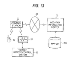
- FIG. 13 is a configurative view of the system according to the embodiment of the present invention.
- a vehicle navigation system 31 and a vehicle remote-control system 32 are provided to the vehicle, and a line control station 33 is connected to a location information center 35 via the Internet 34 .
- the location information center 35 has a map data base 35 a .
- the GPS system is built in the mobile phone 30 , and thus the mobile phone by itself can perform the azimuth angle measurement.
- the mobile phone 30 selects a peripheral map display mode of own vehicle, not only the peripheral map containing own location and the location of own vehicle can be displayed on the LCD display panel of the mobile phone 30 but also the surrounding image of own vehicle can be displayed by switching the display.
- FIG. 14 is a configurative view of the mobile phone employed in this embodiment.
- a difference from the configuration shown in FIG. 2 resides in that a GPS module 14 and an electronic compass module 15 are provided and areas M 32 to M 36 are newly set in the RAM 13 .
- the GPS module 14 by itself can perform the azimuth angle measurement, and transfers latitude and longitude data (current location data) to a controller 10 .
- the electronic compass module 15 measures an azimuth to which the mobile phone is directed, i.e., an azimuth along which the owner (user) of the mobile phone walks, and then outputs this azimuth to the controller 10 as azimuth angle data.
- Own latitude data and own longitude data being measured by the GPS module 14 are stored in M 32 of the RAM 13
- own azimuth angle data being measured by the electronic compass module 15 is stored in M 33
- own vehicle latitude data and own vehicle longitude data being measured by the vehicle navigation system of own vehicle are stored in M 34
- own vehicle azimuth angle data being measured by the electronic compass module 15 that is provided to the vehicle remote-control system is stored in M 35
- the peripheral map data that is received from the location information center 35 is stored in M 36 .
- FIG. 15 is a configurative view of the vehicle remote-control system.
- a difference from the vehicle remote-control system shown in FIG. 15 is that an electronic compass module 9 is provided thereto, areas M 12 to M 13 are newly provided in the RAM 8 , and a vehicle navigation system 31 is connected to the control bus. Own vehicle latitude data and own vehicle longitude data measured by the vehicle navigation system 31 are stored in M 12 , and own vehicle azimuth angle being measured by the electronic compass module 9 is stored in M 13 .
- the mobile phone 30 starts the vehicle remote control system on the display screen in FIG. 9A.
- the vehicle remote-control system 32 is automatically called (ST 50 ).
- the ID authentication is executed (ST 51 )
- the sensor data is transmitted to the mobile phone 30 from the vehicle remote-control system 32 , and then the display shown in FIG. 6 appears on the LCD display panel of the mobile phone (ST 52 ).
- the peripheral map display mode of own vehicle is selected by the predetermined key operation of the mobile phone, such mobile phone is set to the normal mode and then the operation shown in FIG. 11 is executed.
- the peripheral map display mode of own vehicle is selected (ST 53 )
- processes in ST 54 and subsequent steps are executed.
- the peripheral map display mode of own vehicle at first current location data (latitude data, longitude data) of own vehicle and the azimuth angle data of own vehicle are transmitted to the mobile phone (ST 54 ). That is, the data stored in M 12 , M 13 are transmitted to the mobile phone. Then, the connection destination of the mobile phone is switched automatically from the vehicle remote-control system 32 to the location information center 35 (ST 55 ). Then, the mobile phone 30 transmits the current location data of own vehicle and the azimuth angle data of own vehicle, which are received in above ST 54 , and own current location data and own azimuth angle data, which are measure by the GPS module 14 and the electronic compass module 15 respectively, to the location information center 35 (ST 56 ).
- Such location information center 35 when received these data, prepares the peripheral map data, in which the locations of own vehicle and the user are contained, based on the map data base 35 a , and then transmits such map data to the mobile phone 30 . Then, the mobile phone 30 receives the peripheral map data (ST 57 ). Then, such data is displayed on the LCD display panel (ST 58 ).
- FIG. 17 shows an example of the display. In FIG. 17, Q denotes an icon of own vehicle, and P denotes own icon. In this manner, the location information center 35 prepares the peripheral map data having a reduced scale rate, at which own vehicle location and the location of the user can be seen simultaneously without the scroll of the screen, and then transmits such data to the mobile phone 30 .
- an angle to which the icon Q of own vehicle is directed is decided based on the azimuth angle data of own vehicle, and the direction of an arrow P′ that is displayed to overlap with own icon P is decided based on own azimuth angle data.
- the process goes to ST 60 if the particular key is operated, and the process goes back to ST 53 if the particular key is not operated.
- the connection destination is switched from the location information center 35 to the vehicle remote-control system 32 (ST 60 ).
- the surrounding image is received from the vehicle remote-control system 32 (ST 61 ). That is, the surrounding image stored in M 11 is received.
- the surrounding image is displayed on the LCD display panel 11 c (FIG. 7) (ST 62 ).
- the process goes back to ST 59 unless the display mode is ended by the particular key, while the process goes back to ST 53 if the display mode is ended (ST 63 ).
- the mobile phone 30 may transmit the GPS data being measured by the GPS module 14 to the location information center 35 as it is, and then the azimuth angle measurement of the mobile phone 30 may be executed in the location information center 35 based on the GPS data.
- the azimuth angle measurement can be executed according to the D-GPS system, which employs the location information center 35 as the base station, and thus the azimuth angle measurement of the mobile phone 30 can be executed with high precision.
- the vehicle navigation system may be connected to the vehicle remote-control system, and the electronic compass module 9 is not always needed. If this module is not provided, merely the azimuth of own vehicle is not displayed in the mobile phone.
- the remote-control or the display of the surrounding image, etc. may be executed at a remote place by calling the vehicle remote-control system 32 from the mobile phone 30 .
- the surrounding image maybe transmitted to the mobile phone from the vehicle remote-control system side by calling automatically the mobile phone in response to the security sensor that senses the theft of own vehicle.
- the security sensor sensed an accident in the vehicle remote-control system 32 (ST 70 ).
- the mobile phone is called automatically (ST 71 ).
- the alarm is issued on the mobile phone side (ST 72 ).
- the surrounding image being picked up by the image sensor 40 (see FIG. 3) is transmitted to the mobile phone (ST 73 ) Then, this image is displayed on the LCD display panel 11 c (ST 74 ).
- the remote control may be executed at a remote place by calling the vehicle remote-control system from the mobile phone. But merely the display shown in FIG. 6 may be given by transmitting the sensor data to the mobile phone. Unless the remote control from the remote place is executed, the maintenance condition and the trouble condition of own vehicle can be confirmed by displaying the condition of own vehicle on the mobile phone.
- the sensor portion may be constructed by various sensors containing a gasoline sensor, an oil sensor, a battery sensor, etc., which sense various conditions in the vehicle. According to the above configuration, because sensed information of respective sensors are transmitted to the mobile phone and displayed thereon, the maintenance condition, etc. of own vehicle can be checked at the remote place.
- ST 73 and ST 74 may be omitted from FIG. 18.
- the owner of the mobile phone can distinguish such alarm differently from the normal phone call, and therefore such owner can respond to such alarm at once.
- the condition of the vehicle can be checked at the remote location that is away from own vehicle, and also the controlled objects can be set into the desired states by the remote operation even if the user forgot the light OFF, the door lock, etc. at the time of parking.
- the ID authentication is required as the condition to execute this remote operation, the security is increased and this system is excellent in the theft prevention.
Abstract
Sensor data of respective controlled objects of a vehicle are collected by calling a vehicle remote-control system provided to the vehicle via a mobile phone, and then these data are displayed on an LCD display panel 11 c of the mobile phone. In this state, the controlled object to be remotely controlled is selected by operating a cursor (30) and an ON/OFF setting button (31), and then its ON or OFF state is set. At this time, the remote-control command data are transmitted to the vehicle remote-control system from the mobile phone to set the corresponding controlled object. The condition is transmitted once again to the mobile phone as the sensor data, and is displayed on the LCD display panel (11 c).
Description
- The present invention relates to a vehicle control system and a vehicle remote control system capable of controlling predetermined operation portions, which execute door lock ON/OFF, parking brake ON/OFF, engine ON/OFF, etc., by the remote operation instructed by a mobile phone via a communication module equipped to the vehicle side.
- From viewpoints of improvement in drivability and theft prevention, various sensors are installed on doors, a brake, a room light, an engine, etc. of the vehicle. The system for displaying condition of these sensors on a meter panel or for informing the contracted security company of the vehicle location at the time of burglary is put into practical use. In this manner, the drivability can be improved by displaying signals of various sensors on the meter panel, or an emergency measure against the vehicle theft can be taken by linking the sensor information to the system of the security company via the radio.
- However, unless the driver sits on the driver's seat, the sensor information is merely displayed on the meter panel, there is no effect for the condition check, and the drivability is limited. In the system that needs a separate contract with a security company to prevent the theft, not only a special device for that purpose must be equipped to an inside of the vehicle but also merely the condition of the vehicle at the time of occurrence of the theft can be understood, and thus it is impossible to know the condition of the vehicle at any time.
- As the system capable of controlling remotely controlled objects in the vehicle from the outside, there is the keyless entry system. According to this system, it is within point-blank range away from the vehicle by about several meters that the remote control can be executed limitedly. Thus, it is impossible to operate such system at a remote place.
- It is an object of the present invention to provide a vehicle control system and a vehicle remote control system that are capable of grasping and remotely controlling the condition of the vehicle at any time at a remote place by linking sensor portions and a control portion in a vehicle to a mobile phone.
- In order to solve the aforesaid object, the invention is characterized by having the following arrangement.
- (1) A vehicle control system comprising:
- a communication module which communicates with a mobile phone in response to a call issued from the mobile phone;
- an operation control portion which controls a predetermined operation portion of a vehicle;
- a sensor portion which detects information concerning condition of the operation portion; and
- a controller which transmits the information through the communication module to the mobile phone when the controller receives the call from the mobile phone and ID of the mobile phone is authenticated,
- wherein when the controller receives command from the mobile phone, the controller instructs the operation control potion to execute a control corresponding to the command, and transmits, to the mobile phone, the information concerning condition of the operation portion, which is controlled by the operation control portion according to the command, detected by the sensor portion.
- (2) The vehicle control system according to (1), wherein
- the predetermined operation portion includes an image sensor for capturing a peripheral image of the vehicle, and
- the controller instructs the image sensor to capture the peripheral image of the vehicle and transmits the captured peripheral image based on the command from the mobile phone.
- (3) The vehicle control system according to (2) further comprising a vehicle navigation system which measures position of the vehicle and displays information concerning the position of the vehicle and peripheral road information,
- wherein the controller transmits, to the mobile phone, the information concerning the position of the vehicle measured by the vehicle navigation system and the peripheral image captured by the image sensor.
- (4) The vehicle control system according to (1), wherein
- the predetermined operation portion includes an image sensor for capturing a peripheral image of the vehicle and a security sensor for detecting an abnormal state of the vehicle, and
- the controller automatically transmits, to the mobile phone, the information representing the detected abnormal state and the peripheral image captured by the image sensor when the security sensor detects the abnormal state of the vehicle.
- (5) The vehicle control system according to (1), wherein the operation portion includes at least one of engine, air conditioner, door lock, parking brake, light, interior light, image sensor and security sensor.
- (6) A remote-control system for vehicle including a vehicle control system and a mobile phone, the vehicle remote control system comprising:
- the vehicle control system including:
- a communication module which communicates with the mobile phone in response to a cal issued from the mobile phone,
- a operation control portion which controls a predetermined operation portion of the vehicle,
- a sensor portion which detects information concerning condition of the operation portion, and
- a controller which transmits the information through the communication module to the mobile phone when the controller receives the call from the mobile phone and ID of the mobile phone is authenticated, wherein when the controller receives command from the mobile phone, the controller instructs the operation control potion to execute a control corresponding to the command, and transmits, to the mobile phone, the information concerning condition of the operation portion, which is controlled by the operation control portion according to the command, detected by the sensor portion; and
- the mobile phone including:
- a input portion which inputs the command to control the predetermined operation portion of the vehicle, and
- a display portion which displays the information concerning the condition of the operation portion which is controlled by the operation control portion according to the command, which received from the vehicle control system.
- (7) A vehicle control system comprising:
- a communication module which communicates with a mobile phone in response to a call issued from the mobile phone;
- a sensor portion which is installed on a vehicle detects information concerning vehicle condition; and
- a controller which transmits the information detected by the sensor portion through the communication module to the mobile phone when the controller receives the call from the mobile phone and ID of the mobile phone is authenticated.
- (8) The vehicle control system according to (7), wherein the sensor portion includes
- the predetermined operation portion includes a security sensor for detecting an abnormal state of the vehicle, and
- the controller transmits, to the mobile phone, the information representing the detected abnormal state when the security sensor detects the abnormal state of the vehicle.
- (9) The vehicle control system according to (7), wherein the sensor portion detects the condition of at least one of engine, air conditioner, door lock, parking brake, light, interior light, image sensor, security sensor, gasoline and battery.
- (10) A method of controlling a vehicle control system which includes a communication module for communicating with a mobile phone, an operation control portion for controlling a predetermined operation portion of a vehicle, a sensor portion for detecting information concerning condition of the operation portion and a controller for transmitting the information through the communication module, the method comprising the steps of:
- communicating with the mobile phone when the communication module receives a call issued from the mobile phone;
- transmitting the information by the controller through the communication module to the mobile phone when ID of the mobile phone is authenticated; and
- instructing, when the controller receives command from the mobile phone, the operation control portion to execute a control corresponding to the command, and transmitting, to the mobile phone, the information concerning condition of the operation portion, which is controlled by the operation control portion according to the command, detected by the sensor portion.
- (11) A method of controlling a vehicle control system comprising:
- establishing communication between a vehicle and a mobile phone in response to a call issued from the mobile phone; and
- transmitting information concerning vehicle condition to the mobile phone when ID of the mobile phone is authenticated.
- FIG. 1 is a configurative view of a vehicle remote-control system as a first embodiment of the present invention.
- FIG. 2 is a configurative view of a mobile phone.
- FIG. 3 is a configurative view of an image sensor control portion.
- FIG. 4 is a view showing a correlation table between remote control commands and command codes.
- FIG. 5 is a configurative view of a hardware of a remote-control command decoder.
- FIG. 6 is a view showing an example of display in the mobile phone.
- FIG. 7 is a view showing another example of display in the mobile phone.
- FIG. 8 is a flowchart showing an initializing operation of the vehicle remote control system.
- FIGS. 9A to 9D are sequential views of a display screen of the mobile phone when the vehicle remote control system is started.
- FIG. 10 is a flowchart showing an operation of the vehicle remote control system.
- FIG. 11 is a flowchart showing an operation of the vehicle remote control system.
- FIG. 12 is a flowchart showing an operation of the vehicle remote control system.
- FIG. 13 is a configurative view of a system of another embodiment of the present invention.
- FIG. 14 is a configurative view of the mobile phone.
- FIG. 15 is a configurative view of the vehicle remote-control system.
- FIG. 16 is a flowchart showing an overall operation of the same system.
- FIG. 17 is a view showing an example of display in the mobile phone.
- FIG. 18 is a flowchart showing an overall operation of still another embodiment of the present invention.
- A vehicle remote control system according to an embodiment of the present invention will be explained in detail hereinafter.
- FIG. 1 is a configurative view of a remote-control system on the vehicle side (hereinafter refer to vehicle remote-control system).
- To a
controller 1 are connected a mobilephone communication module 2 for communicating with a mobile phone in response to the call issued from the mobile phone; a remote-control portion 3 for controlling predetermined operation portions of the vehicle such as an air conditioner, door locks, a parking brake, a light, etc. as controlled objects; an imagesensor control portion 4 for picking up an image around the vehicle; and asensor portion 5 for sensing conditions of various controlled objects of the vehicle such as an air-conditioner sensor, door lock sensors, a parking brake sensor, etc. The remote-control portion 3 and the imagesensor control portion 4 correspond to a control portion in the present invention. In this case, a signal being sensed by thesensor portion 5 is decoded by asensor decoder 6 and then input into thecontroller 1. A control program and a decode program, which decodes remote control commands being supplied from the mobile phone side, are stored in aROM 7 that is connected to thecontroller 1. An ID used to execute ID authentication of the mobile phone, a mobile phone number, sensor data, surrounding image, etc. are stored in aRAM 8. More particularly, ID (in the embodiment, ID=4806) is stored in an area M1, the mobile phone number is stored in an area M2, data from engine, air-conditioner, door lock, parking brake, light, room light, security, and image sensors are stored in areas M3 to M1 respectively, and a surrounding image picked up by the imagesensor control portion 4 is stored in an area M11. In this case, “1” of the sensor data stored in M3 to M10 indicates ON and “0” indicates OFF. The security sensor in thesensor portion 5 is constructed by a sensor that senses whether or not the inserted electronic key, for example, can be authenticated. - When the mobile
phone communication module 2 senses the call issued from the mobile phone, thecontroller 1 decides whether or not the subsequent ID coincides with the ID stored in M1. Then, if they coincide with each other, thecontroller 1 executes the control in response to the remote control command being transmitted subsequently from the mobile phone. As described later, thecontroller 1 transmits the sensor data stored in M3 to M10 to the mobile phone, receives the remote-control command issued from the mobile phone, and outputs a control signal to the remote-control portion 3. After the control made by the remote-control portion 3 is ended, thecontroller 1 updates the sensor data stored in M3 to M10 to reflect the ON/OFF control and then transmits the updated sensor data to the mobile phone. The sensor data are displayed on theLCD display panel 11 c. - FIG. 2 is a configurative view of the mobile phone.
- In this mobile phone, a mobile
phone function block 11, an F-memory (or memory card) 12 and aRAM 13 are connected to acontroller 10. The mobilephone function block 11 includes a mobilephone communication module 11 a, akeyboard 11 b and anLCD display panel 11 c. The mobilephone function block 11 has a function that executes the data communication between the mobilephone communication module 2 and this block by phone-calling the vehicle remote-control system in FIG. 1, in addition to the function as the normal mobile phone. Thekey board 11 b is used to input the phone number and the commands, and theLCD display panel 11 c is used to display various messages and respective sensor data from thesensor portion 5 in FIG. 1. - A stored control program, operation icon data, remote control command data, etc. are stored in the
flash memory 12. InRAM 13, the data transmitted from the area M3 to the area M11 in FIG. 1 are stored in an area M23 to an area M31, icon data of the vehicle are stored in an area M20, the ID is stored in an area M21, and the phone number of the vehicle remote-control system is stored in an area M22. - When the remote control is executed by calling the vehicle remote-control system, at first the ID is input via the
key board 11 b. Then, when the ID authentication is executed on the vehicle remote-control system side, the sensor data stored in M3 to M10 in the vehicle remote-control system are transmitted to M23 to M30 in the mobile phone. At this time, the icon data as well as ON/OFF conditions of respective sensors are displayed on theLCD display panel 11 c. The operator sets ON/OFFs of the controlled objects such as air conditioner, door lock, etc. according to this display, then converts these settings into the command data as the remote control command, and then transmits the data to the vehicle remote-control system side. When the vehicle remote-control system receives the command data, such system drives the remote-control portion 3 in response to such data to execute ON/OFF-control of the predetermined controlled object. The sensor data stored in M3 to M10 are updated at this time. The updated sensor data are transmitted once again to the mobile phone. Such sensor data are displayed on theLCD display panel 11 c. - Therefore, when the owner of the mobile phone executes a predetermined operation applied to the controlled object of the vehicle on the
LCD display panel 11 c, the remote control is executed based on this operation. Then, the result of the remote control is displayed on theLCD display panel 11 c. - Accordingly, the remote control of respective controlled objects in the vehicle remote-control system can be executed from the mobile phone side. In this case, when the image sensor is set to ON, the surrounding image round the vehicle, which is picked up by the image
sensor control portion 4, is stored in M11 of the vehicle remote-control system. Then, this surrounding image is transmitted to M31 in the mobile phone. This surrounding image is displayed on theLCD display panel 11 c. - FIG. 3 is a configurative view of the image
sensor control portion 4. Animage sensor 40 is installed on an appropriate position in the vehicle, and can pick up the image round the vehicle via the vehicle window. Thisimage sensor 40 can be rotated/driven by a vertical-direction drive motor 41 in the vertical direction and also can be rotated/driven by a horizontal-direction drive motor 41 in the horizontal direction. The imaging direction of theimage sensor 40 can be set in any direction by controlling twomotors motor control circuit 43 controls themotors image sensor 40 is encoded (compressed) by animage data encoder 44, and then transferred to thecontroller 1. In this case, if theimage sensor 40 is constructed to sense the moving picture, the image data is encoded by the compression technology such as MPEG2, etc., for example. If the image picked up by theimage sensor 40 is the still picture, such image is encoded into JPEG image, or the like. - FIG. 4 shows correlations between the remote control commands and the command codes. In an example shown in FIG. 4, the command code consists of 4 bits, and 1 bit is used to turn ON/OFF and to drive the image sensor by a predetermined angle in upward/downward/leftward/rightward directions. Therefore, when the command is transmitted to the vehicle remote-control system side from the mobile phone, the command code (4 bits)+the command content (1 bit) are transmitted.
- The command code and the command content are decoded by a remote-control command decoder in the
ROM 7 and converted into a predetermined signal, and then transferred to the remote-control portion 3. In this case, this remote-control command decoder can be constructed by a hardware. FIG. 5 shows an example of the remote-control command decoder when such command decoder is formed of the hardware. - More particularly, the command code transferred from the
controller 1 is decoded by acommand decoder 20. The decoded output is input into a T-type flip-flop 21 to form each control signal. This control signal and the 1-bit command content are output to the remote-control portion 3. Then, the remote-control portion 3 controls the corresponding controlled object based on the data. For example, if the remote-control command code is “0001” and the command content is “1”, the engine is turned ON. If the command content is “0”, the engine is turned OFF. - FIG. 6 shows displayed states and a part of the keyboard on the
LCD display panel 11 c of the mobile phone. FIG. 6 is an example of display when respective controlled objects of the vehicle are to be remotely controlled from the mobile phone side. - A vehicle icon stored in M 20 and various sensor positions positioned on this icon respectively are displayed on the
LCD display panel 11 c. The sensor positions that are to be selected on the screen can be changed by operatingcursor keys 30 on thekey board 11 b. The ON/OFF-state of the selected sensor position can be decided by operating an ON/OFF set button 31. This ON/OFF set button 31 executes a toggle operation, and switches ON/OFF of the selected sensor alternatively in answer to the operation of the button. - FIG. 7 shows the state that the image picked up by the
image sensor 40 is displayed on theLCD display panel 11 c of the mobile phone. This mode is executed when a predetermined operation is executed in the mobile phone. In this mode, thecursor keys 30 on thekeyboard 11 b are used to issue rotation-angle increase/decrease commands in upward/downward/leftward/rightward directions of theimage sensor 40. Theimage sensor 40 is rotated by a predetermined angle in the direction, which corresponds to the concerned key, every time when each of thecursor keys 30 is pushed once. In other words, the screen is shifted by a predetermined distance in the direction that corresponds to the concerned key. In this mode, abutton 31 positioned in the center of the cursor keys functions as a shutter button. The image data that is being displayed when theshutter button 31 is pushed (in the case of the moving picture, the image data that is obtained by converting the moving picture into the still picture when the shutter button is pushed) is stored in a predetermined area of theRAM 13 by operating thisshutter button 31. - Particular operations of the mobile phone and the vehicle remote-control system will be explained with reference to FIG. 8 and subsequent drawings hereunder.
- FIG. 8 shows an initializing operation of the vehicle remote-control system by the mobile phone. The initializing operation is an operation of setting/registering the ID to the vehicle remote-control system side to make it possible for the vehicle remote-control system to authenticate the ID of the mobile phone.
- When an application program (car remote control system) of the vehicle remote control system is started by the mobile phone, a display screen in FIG. 9A appears and then a display screen in FIG. 9B appears. At this time, in ST 1, the user of the mobile phone makes a call to the vehicle phone of own vehicle. As shown in FIG. 2, the phone number of own vehicle is stored in the phone number column of the vehicle remote-control system in M22. Then, a button B1 is clicked in the display state in FIG. 9B. Then, the screen is shifted to an A screen in FIG. 9C, and thus a mode in which the initial ID and own station mobile phone number are input is set. In other words, an initial ID inputting mode is set in ST2, and then the initial ID and the mobile phone number of own station are input in ST3. In this example, the initial ID is 4806 and the mobile phone number of own vehicle is 090-1234-0000. Then, the initial ID and the mobile phone number are transmitted to own vehicle (ST4). In the vehicle remote-control system of own vehicle, the transmitted initial ID is registered in the M1 and the mobile phone number is registered in the M2 (ST5). With the above processes, the initializing operation is ended.
- In this case, it is desired that, before the initial ID is registered, it should be checked in the initializing operation by any approach whether or not the owner of the mobile phone is the valid person.
- FIG. 10 is a flowchart showing an overall operation of the system when the vehicle remote control system is started after the initial ID is set.
- At first, in ST 10, the vehicle remote control system is started on the
LCD display panel 11 c of the mobile phone. According to the start of the system, the mobilephone communication module 11 a of the mobile phone calls automatically the vehicle remote-control system and makes a connection thereto. At this time, the screen of theLCD display panel 11 c is shifted to the display condition in FIG. 9B. When a button B2 is clicked at this stage, the screen is shifted to an ID input screen in FIG. 9D. Then, the operator inputs the ID onto the display screen (ST11). Then, the mobilephone communication module 11 a transmits the input ID to the vehicle remote-control system (ST12). Then, in the vehicle remote-control system, the ID authentication is executed to check whether or not the received ID coincides with the ID stored in M1 (ST13). If the ID authentication is OK, the sensor data at that time are stored in M3 to M10 (ST14). Then, the sensor data stored in M3 to M10 are transmitted to the mobile phone via the mobile phone communication module 2 (ST15). Then, the mobile phone receives the sensor data (ST16), and then stores the data in M23 to M30 (ST17). Then, as shown in FIG. 6, the states of the sensors are displayed on theLCD display panel 11 c of the mobile phone (ST18). - In addition, in FIG. 11, the user's operation made by the
cursor keys 30 is sensed (ST20). The set operation made by the ON/OFF setting button 31 is sensed (ST21). Respective sensors are provided to correspond to the controlled objects. Thus, the sensor, i.e., the controlled object corresponding to the sensor position can be selected by operating thecursor keys 30. The selected controlled object is highlight-displayed. For example, in FIG. 6, the door lock is selected as the controlled object. The ON/OFF setting button 31 is used to set the ON/OFF-state of the selected controlled object. The ON/OFF setting button 31 sets ON/OFF of the selected controlled object by its toggle operation, and sets ON and OFF alternatively. - Then, the remote-control command data of the controlled object, which is set to ON or OFF by the ON/
OFF setting button 31, is transmitted to the vehicle remote-control system (ST22). Then, the vehicle remote-control system receives the remote-control command data (ST23). Then, the data is decoded by the remote-control command decoder (ST24). The control signal is generated and output to the remote-control portion 3 (ST25). Thus, the remote-control portion 3 sets the concerned controlled object to its ON or OFF state. Then, thesensor portion 5 sets the sensor data in M3 to M10 (ST26). Then, the sensor data stored in M3 to M10 are transmitted to the mobile phone (ST27). Then, the mobile phone receives the sensor data (ST28). Then, the display shown in FIG. 6 appears again on theLCD display panel 11 c (ST29). - With the above, first the user checks states of respective controlled objects of own vehicle on the
LCD display panel 11 c of the mobile phone based on the sensor data, and then sets the state of the desired controlled object into its ON or OFF state by using thecursor keys 30 and the ON/OFF setting button 31. Then, when the control operation is applied to the controlled object on the vehicle side, the updated sensor data is displayed again on theLCD display panel 11 c. As a result, the user can execute the remote control of the controlled objects in own vehicle by using the mobile phone. -
Other Embodiment 1 - In this other embodiment of the present invention, a vehicle navigation system is provided to the vehicle remote-control system. The current location data (latitude, longitude data) of own vehicle, which are acquired by the vehicle navigation system, as well as the surrounding image, which is picked up by the image sensor, are transmitted to the mobile phone, and then the current location of own vehicle as well as the peripheral map is displayed in the mobile phone, and also the image that is picked up by the
image sensor 40 at this time is displayed by the screen switching operation. Since an electronic compass is provided to the vehicle remote-control system, the direction along which the vehicle is now directed (own vehicle azimuth angle) is also transmitted to the mobile phone, and thus the display direction of own vehicle to be displayed is set. In this case, a location information center is provided separately to get the peripheral map, and a GPS function is installed into the mobile phone. In the location information center, the peripheral map data containing the current location of own vehicle and the current location of the mobile phone is prepared based on the current location data of own vehicle and the current location data of the mobile phone, and then this data is transmitted to the mobile phone. In this case, when the image sensor is selected in above ST20 and then this image sensor is set to its ON-state by the ON/OFF setting button 31, an operation shown in FIG. 12 is carried out. More particularly, theimage sensor 40 is turned ON and the movement control of the imaging direction is executed in response to the operation of the cursor key (ST40). Thus, the image data being picked up by theimage sensor 40 is stored in M11 of the vehicle remote-control system (ST41). Then, this data in M11 is transmitted to the mobile phone (ST42). The received image data is stored in M31 of the mobile phone (ST43). This image data is displayed as shown in FIG. 7 (ST44) Then, if the screen is shifted by the operation of the cursor key in the display state in FIG. 7 (ST45), the process goes back to ST40 and similar operations are executed subsequently. - FIG. 13 is a configurative view of the system according to the embodiment of the present invention. A
vehicle navigation system 31 and a vehicle remote-control system 32 are provided to the vehicle, and aline control station 33 is connected to alocation information center 35 via theInternet 34. Thelocation information center 35 has amap data base 35 a. In the present embodiment, the GPS system is built in themobile phone 30, and thus the mobile phone by itself can perform the azimuth angle measurement. - According to the above configuration, if the
mobile phone 30 selects a peripheral map display mode of own vehicle, not only the peripheral map containing own location and the location of own vehicle can be displayed on the LCD display panel of themobile phone 30 but also the surrounding image of own vehicle can be displayed by switching the display. - FIG. 14 is a configurative view of the mobile phone employed in this embodiment. A difference from the configuration shown in FIG. 2 resides in that a
GPS module 14 and anelectronic compass module 15 are provided and areas M32 to M36 are newly set in theRAM 13. TheGPS module 14 by itself can perform the azimuth angle measurement, and transfers latitude and longitude data (current location data) to acontroller 10. Theelectronic compass module 15 measures an azimuth to which the mobile phone is directed, i.e., an azimuth along which the owner (user) of the mobile phone walks, and then outputs this azimuth to thecontroller 10 as azimuth angle data. Own latitude data and own longitude data being measured by theGPS module 14 are stored in M32 of theRAM 13, and own azimuth angle data being measured by theelectronic compass module 15 is stored in M33. Also, own vehicle latitude data and own vehicle longitude data being measured by the vehicle navigation system of own vehicle are stored in M34, and also own vehicle azimuth angle data being measured by theelectronic compass module 15 that is provided to the vehicle remote-control system is stored in M35. The peripheral map data that is received from thelocation information center 35 is stored in M36. - FIG. 15 is a configurative view of the vehicle remote-control system. A difference from the vehicle remote-control system shown in FIG. 15 is that an
electronic compass module 9 is provided thereto, areas M12 to M13 are newly provided in theRAM 8, and avehicle navigation system 31 is connected to the control bus. Own vehicle latitude data and own vehicle longitude data measured by thevehicle navigation system 31 are stored in M12, and own vehicle azimuth angle being measured by theelectronic compass module 9 is stored in M13. - Next, an operation of the vehicle remote control system in the present embodiment will be explained with reference to FIG. 16 hereunder.
- At first, the
mobile phone 30 starts the vehicle remote control system on the display screen in FIG. 9A. When this vehicle remote control system is started, the vehicle remote-control system 32 is automatically called (ST50). Then, the ID authentication is executed (ST51) Then, the sensor data is transmitted to themobile phone 30 from the vehicle remote-control system 32, and then the display shown in FIG. 6 appears on the LCD display panel of the mobile phone (ST52). At this time, unless the peripheral map display mode of own vehicle is selected by the predetermined key operation of the mobile phone, such mobile phone is set to the normal mode and then the operation shown in FIG. 11 is executed. Then, if the peripheral map display mode of own vehicle is selected (ST53), processes in ST54 and subsequent steps are executed. - In the peripheral map display mode of own vehicle, at first current location data (latitude data, longitude data) of own vehicle and the azimuth angle data of own vehicle are transmitted to the mobile phone (ST 54). That is, the data stored in M12, M13 are transmitted to the mobile phone. Then, the connection destination of the mobile phone is switched automatically from the vehicle remote-
control system 32 to the location information center 35 (ST55). Then, themobile phone 30 transmits the current location data of own vehicle and the azimuth angle data of own vehicle, which are received in above ST54, and own current location data and own azimuth angle data, which are measure by theGPS module 14 and theelectronic compass module 15 respectively, to the location information center 35 (ST56). Suchlocation information center 35, when received these data, prepares the peripheral map data, in which the locations of own vehicle and the user are contained, based on themap data base 35 a, and then transmits such map data to themobile phone 30. Then, themobile phone 30 receives the peripheral map data (ST57). Then, such data is displayed on the LCD display panel (ST58). FIG. 17 shows an example of the display. In FIG. 17, Q denotes an icon of own vehicle, and P denotes own icon. In this manner, thelocation information center 35 prepares the peripheral map data having a reduced scale rate, at which own vehicle location and the location of the user can be seen simultaneously without the scroll of the screen, and then transmits such data to themobile phone 30. For this reason, the user can grasp not only the location of own vehicle but also the relationship between the locations of own vehicle and the user by snatching a glance at this peripheral map data. In this case, in the displaying operation, an angle to which the icon Q of own vehicle is directed is decided based on the azimuth angle data of own vehicle, and the direction of an arrow P′ that is displayed to overlap with own icon P is decided based on own azimuth angle data. - Then, it is decided whether or not the current display content should be switched to the surrounding image (ST 59). In this decision, it is decided whether or not a particular key of the mobile phone is operated. Then, the process goes to ST60 if the particular key is operated, and the process goes back to ST53 if the particular key is not operated. In ST60, the connection destination is switched from the
location information center 35 to the vehicle remote-control system 32 (ST60). Then, the surrounding image is received from the vehicle remote-control system 32 (ST61). That is, the surrounding image stored in M11 is received. Then, the surrounding image is displayed on theLCD display panel 11 c (FIG. 7) (ST62). Then, the process goes back to ST59 unless the display mode is ended by the particular key, while the process goes back to ST53 if the display mode is ended (ST63). - In this case, the
mobile phone 30 may transmit the GPS data being measured by theGPS module 14 to thelocation information center 35 as it is, and then the azimuth angle measurement of themobile phone 30 may be executed in thelocation information center 35 based on the GPS data. In this case, the azimuth angle measurement can be executed according to the D-GPS system, which employs thelocation information center 35 as the base station, and thus the azimuth angle measurement of themobile phone 30 can be executed with high precision. Also, at least the vehicle navigation system may be connected to the vehicle remote-control system, and theelectronic compass module 9 is not always needed. If this module is not provided, merely the azimuth of own vehicle is not displayed in the mobile phone. -
Other Embodiment 2 - In the above embodiments, the remote-control or the display of the surrounding image, etc. may be executed at a remote place by calling the vehicle remote-
control system 32 from themobile phone 30. However, when the abnormal condition is caused, the surrounding image maybe transmitted to the mobile phone from the vehicle remote-control system side by calling automatically the mobile phone in response to the security sensor that senses the theft of own vehicle. In other words, as shown in FIG. 18, if the security sensor sensed an accident in the vehicle remote-control system 32 (ST70). Then, the mobile phone is called automatically (ST71). Then, the alarm is issued on the mobile phone side (ST72). Also, the surrounding image being picked up by the image sensor 40 (see FIG. 3) is transmitted to the mobile phone (ST73) Then, this image is displayed on theLCD display panel 11 c (ST74). -
Other Embodiment 3 - In the above embodiments, the remote control may be executed at a remote place by calling the vehicle remote-control system from the mobile phone. But merely the display shown in FIG. 6 may be given by transmitting the sensor data to the mobile phone. Unless the remote control from the remote place is executed, the maintenance condition and the trouble condition of own vehicle can be confirmed by displaying the condition of own vehicle on the mobile phone. In this case, the sensor portion may be constructed by various sensors containing a gasoline sensor, an oil sensor, a battery sensor, etc., which sense various conditions in the vehicle. According to the above configuration, because sensed information of respective sensors are transmitted to the mobile phone and displayed thereon, the maintenance condition, etc. of own vehicle can be checked at the remote place.
- Also, ST 73 and ST74 may be omitted from FIG. 18. In this case, if the mobile phone is called in ST71 to cause the mobile phone side to issue the alarm therefrom, the owner of the mobile phone can distinguish such alarm differently from the normal phone call, and therefore such owner can respond to such alarm at once.
- According to the present invention, since the mobile phone is utilized, the condition of the vehicle can be checked at the remote location that is away from own vehicle, and also the controlled objects can be set into the desired states by the remote operation even if the user forgot the light OFF, the door lock, etc. at the time of parking. In addition, since the ID authentication is required as the condition to execute this remote operation, the security is increased and this system is excellent in the theft prevention.
- Also, since the abnormality is informed of the mobile phone when the security sensor informs the accident and also several images being picked up by the image sensor are automatically transmitted, the theft can be suppressed. Also, since the surrounding image is automatically transmitted, the user can take quickly the countermeasure even when the vehicle is stolen.
Claims (11)
1. A vehicle control system comprising:
a communication module which communicates with a mobile phone in response to a call issued from the mobile phone;
an operation control portion which controls a predetermined operation portion of a vehicle;
a sensor portion which detects information concerning condition of the operation portion; and
a controller which transmits the information through the communication module to the mobile phone when the controller receives the call from the mobile phone and ID of the mobile phone is authenticated,
wherein when the controller receives command from the mobile phone, the controller instructs the operation control portion to execute a control corresponding to the command, and transmits, to the mobile phone, the information concerning condition of the operation portion, which is controlled by the operation control portion according to the command, detected by the sensor portion.
2. The vehicle control system according to claim 1 , wherein
the predetermined operation portion includes an image sensor for capturing a peripheral image of the vehicle, and
the controller instructs the image sensor to capture the peripheral image of the vehicle and transmits the captured peripheral image based on the command from the mobile phone.
3. The vehicle control system according to claim 2 further comprising a vehicle navigation system which measures position of the vehicle and displays information concerning the position of the vehicle and peripheral road information,
wherein the controller transmits, to the mobile phone, the information concerning the position of the vehicle measured by the vehicle navigation system and the peripheral image captured by the image sensor.
4. The vehicle control system according to claim 1 , wherein
the predetermined operation portion includes an image sensor for capturing a peripheral image of the vehicle and a security sensor for detecting an abnormal state of the vehicle, and
the controller automatically transmits, to the mobile phone, the information representing the detected abnormal state and the peripheral image captured by the image sensor when the security sensor detects the abnormal state of the vehicle.
5. The vehicle control system according to claim 1 , wherein the operation portion includes at least one of engine, air conditioner, door lock, parking brake, light, interior light, image sensor and security sensor.
6. A remote-control system for vehicle including a vehicle control system and a mobile phone, the vehicle remote control system comprising:
the vehicle control system including:
a communication module which communicates with the mobile phone in response to a cal issued from the mobile phone,
a operation control portion which controls a predetermined operation portion of the vehicle,
a sensor portion which detects information concerning condition of the operation portion, and
a controller which transmits the information through the communication module to the mobile phone when the controller receives the call from the mobile phone and ID of the mobile phone is authenticated, wherein when the controller receives command from the mobile phone, the controller instructs the operation control potion to execute a control corresponding to the command, and transmits, to the mobile phone, the information concerning condition of the operation portion, which is controlled by the operation control portion according to the command, detected by the sensor portion; and
the mobile phone including:
a input portion which inputs the command to control the predetermined operation portion of the vehicle, and
a display portion which displays the information concerning the condition of the operation portion which is controlled by the operation control portion according to the command, which received from the vehicle control system.
7. A vehicle control system comprising:
a communication module which communicates with a mobile phone in response to a call issued from the mobile phone;
a sensor portion which is installed on a vehicle detects information concerning vehicle condition; and
a controller which transmits the information detected by the sensor portion through the communication module to the mobile phone when the controller receives the call from the mobile phone and ID of the mobile phone is authenticated.
8. The vehicle control system according to claim 7 , wherein the sensor portion includes
the predetermined operation portion includes a security sensor for detecting an abnormal state of the vehicle, and
the controller transmits, to the mobile phone, the information representing the detected abnormal state when the security sensor detects the abnormal state of the vehicle.
9. The vehicle control system according to claim 7 , wherein the sensor portion detects the condition of at least one of engine, air conditioner, door lock, parking brake, light, interior light, image sensor, security sensor, gasoline and battery.
10. A method of controlling a vehicle control system which includes a communication module for communicating with a mobile phone, an operation control portion for controlling a predetermined operation portion of a vehicle, a sensor portion for detecting information concerning condition of the operation portion and a controller for transmitting the information through the communication module, the method comprising the steps of:
communicating with the mobile phone when the communication module receives a call issued from the mobile phone;
transmitting the information by the controller through the communication module to the mobile phone when ID of the mobile phone is authenticated; and
instructing, when the controller receives command from the mobile phone, the operation control portion to execute a control corresponding to the command, and transmitting, to the mobile phone, the information concerning condition of the operation portion, which is controlled by the operation control portion according to the command, detected by the sensor portion.
11. A method of controlling a vehicle control system comprising:
establishing communication between a vehicle and a mobile phone in response to a call issued from the mobile phone; and
transmitting information concerning vehicle condition to the mobile phone when ID of the mobile phone is authenticated.
Applications Claiming Priority (2)
| Application Number | Priority Date | Filing Date | Title |
|---|---|---|---|
| JP2002109474A JP3873799B2 (en) | 2002-04-11 | 2002-04-11 | Car remote control system |
| JPP2002-109474 | 2002-04-11 |
Publications (2)
| Publication Number | Publication Date |
|---|---|
| US20030193390A1 true US20030193390A1 (en) | 2003-10-16 |
| US6937141B2 US6937141B2 (en) | 2005-08-30 |
Family
ID=28786585
Family Applications (1)
| Application Number | Title | Priority Date | Filing Date |
|---|---|---|---|
| US10/411,614 Expired - Fee Related US6937141B2 (en) | 2002-04-11 | 2003-04-10 | Car control system and vehicle remote control system |
Country Status (2)
| Country | Link |
|---|---|
| US (1) | US6937141B2 (en) |
| JP (1) | JP3873799B2 (en) |
Cited By (35)
| Publication number | Priority date | Publication date | Assignee | Title |
|---|---|---|---|---|
| US20040049325A1 (en) * | 2002-09-06 | 2004-03-11 | Omega Patents, L.L.C. | Vehicle control system with selectable vehicle style image and associated methods |
| US20050085221A1 (en) * | 2003-10-21 | 2005-04-21 | General Motors Corporation | Remotely controlling vehicle functions |
| US20050151630A1 (en) * | 2004-01-13 | 2005-07-14 | Denso Corporation | Automotive antitheft system |
| WO2005085021A1 (en) * | 2004-03-08 | 2005-09-15 | Sekhar Padmanabhan | Vehicle security system using short messaging services / internet |
| US20060158349A1 (en) * | 2005-01-20 | 2006-07-20 | General Motors Corporation | Method for controlling a remote monitoring device |
| WO2006090562A1 (en) * | 2005-02-22 | 2006-08-31 | Toyota Jidosha Kabushiki Kaisha | Vehicle remote control apparatus and method |
| US20060254986A1 (en) * | 2005-05-11 | 2006-11-16 | Honeywell International, Inc. | Oil management system |
| US20060258379A1 (en) * | 2005-05-13 | 2006-11-16 | General Motors Corporation | Method and system for delivering telematics services via a handheld communication device |
| US7218925B2 (en) | 2002-06-06 | 2007-05-15 | General Motors Corporation | Method of initiating a telematics service |
| US20080004788A1 (en) * | 2006-06-28 | 2008-01-03 | Dorfstatter Walter A | Automatic communication of subscription-specific messages to a telematics equipped vehicle |
| EP1909072A1 (en) | 2006-10-06 | 2008-04-09 | Harman Becker Automotive Systems GmbH | Vehicle electronic system coupling a mobile navigation module to a vehicle audio module |
| US20090134991A1 (en) * | 2007-11-26 | 2009-05-28 | General Motors Corporation | Automatically communicating reminder messages to a telematics-equipped vehicle |
| US20090251279A1 (en) * | 2005-07-19 | 2009-10-08 | Philipp Paul Spangenberg | Identifying and/or Locking System for Identifying and/or Unblocking a Technical System, and Method for the Operation Thereof |
| US7684915B1 (en) * | 2006-07-12 | 2010-03-23 | Vantage Mobility International, Llc | Controlled access for light duty motor vehicle |
| US20100223006A1 (en) * | 2007-10-22 | 2010-09-02 | Mitsuru Sasaki | Navigation system, portable terminal device, and in-vehicle device |
| US20100257195A1 (en) * | 2009-02-20 | 2010-10-07 | Nikon Corporation | Mobile information device, image pickup device, and information acquisition system |
| CN101883183A (en) * | 2010-06-13 | 2010-11-10 | 中兴通讯股份有限公司 | Remote control method and system for mobile terminal and mobile terminal |
| US20110105103A1 (en) * | 2009-10-30 | 2011-05-05 | Immersion Corporation | Interfacing a Mobile Device with a Computer |
| WO2012049693A1 (en) * | 2010-10-15 | 2012-04-19 | Vipin Kumar | Micro detective (a.t.e.d) anti theftion emergency device |
| US20120221176A1 (en) * | 2011-02-24 | 2012-08-30 | Hon Hai Precision Industry Co., Ltd. | Control device and method for adjusting flight direction of unmanned aerial vehicle using the same |
| US20130027193A1 (en) * | 2011-07-28 | 2013-01-31 | Hon Hai Precision Industry Co., Ltd. | Remote control system and method |
| US20130257591A1 (en) * | 2012-03-29 | 2013-10-03 | Fujitsu Ten Limited | Vehicle controller |
| US8650656B1 (en) * | 2006-10-30 | 2014-02-11 | At&T Intellectual Property Ii, L.P. | Method and apparatus for user authentication |
| CN103765828A (en) * | 2011-09-06 | 2014-04-30 | 大众汽车有限公司 | Vehicle comfort system for using and/or controlling vehicle functions with the assistance of mobile device |
| CN104345733A (en) * | 2013-08-07 | 2015-02-11 | 大众汽车有限公司 | Controlling of the automatic driving process of a vehicle |
| US20150302733A1 (en) * | 2014-04-18 | 2015-10-22 | Gentex Corporation | Trainable transceiver and mobile communications device diagnostic systems and methods |
| CN106761128A (en) * | 2016-11-03 | 2017-05-31 | 征博科技(深圳)有限公司 | The control method and control system of electric tail gate |
| WO2017105913A1 (en) * | 2015-12-17 | 2017-06-22 | Continental Automotive Systems, Inc. | Thief alert system using a camera |
| CN107027096A (en) * | 2016-01-29 | 2017-08-08 | 法拉第未来公司 | The tele-control system of vehicle |
| WO2018136857A1 (en) * | 2017-01-23 | 2018-07-26 | TSI Products, Inc. | Vehicle roof fan |
| CN108459550A (en) * | 2017-02-20 | 2018-08-28 | 现代自动车株式会社 | Vehicle and method for controlling a vehicle and equipment |
| US20180357898A1 (en) * | 2017-06-07 | 2018-12-13 | GM Global Technology Operations LLC | Vehicle locator and guide |
| CN111216554A (en) * | 2015-01-26 | 2020-06-02 | 哈曼国际工业有限公司 | Controlling vehicle systems with mobile devices |
| US10737550B2 (en) | 2017-02-03 | 2020-08-11 | Toyota Jidosha Kabushiki Kaisha | Remote air conditioning start system, center server and method for controlling remote air conditioning start system |
| WO2020225341A1 (en) * | 2019-05-09 | 2020-11-12 | Jaguar Land Rover Limited | Apparatus and method for use with a vehicle |
Families Citing this family (44)
| Publication number | Priority date | Publication date | Assignee | Title |
|---|---|---|---|---|
| US10118576B2 (en) | 2002-06-11 | 2018-11-06 | Intelligent Technologies International, Inc. | Shipping container information recordation techniques |
| TWI276309B (en) * | 2004-05-11 | 2007-03-11 | Yi-Shiuan Shau | Device and method for controlling vehicle from remote site |
| JP4126563B2 (en) * | 2004-12-15 | 2008-07-30 | 日本電気株式会社 | Data collection system and data collection method |
| JP4561410B2 (en) * | 2005-03-04 | 2010-10-13 | トヨタ自動車株式会社 | Vehicle remote control system and in-vehicle device |
| US20080164972A1 (en) * | 2005-06-15 | 2008-07-10 | Naoki Taki | Remote Operation Apparatus and Service Center |
| JP4539467B2 (en) * | 2005-07-06 | 2010-09-08 | トヨタ自動車株式会社 | Portable information terminal and screen display method of portable information terminal |
| JP4544091B2 (en) * | 2005-08-12 | 2010-09-15 | 三菱自動車工業株式会社 | Vehicle information setting device |
| US7825780B2 (en) * | 2005-10-05 | 2010-11-02 | Telecommunication Systems, Inc. | Cellular augmented vehicle alarm notification together with location services for position of an alarming vehicle |
| JP4598734B2 (en) * | 2006-09-12 | 2010-12-15 | 株式会社エヌ・ティ・ティ・ドコモ | Key information distribution server, portable terminal, key information distribution system, and application program for vehicle setting |
| US9430945B2 (en) | 2006-12-20 | 2016-08-30 | Johnson Controls Technology Company | System and method for providing route calculation and information to a vehicle |
| JP5676108B2 (en) | 2006-12-20 | 2015-02-25 | ジョンソン コントロールズ テクノロジー カンパニーJohnson Controls Technology Company | Remote display reproduction system |
| JP5162601B2 (en) * | 2007-01-23 | 2013-03-13 | ジョンソン コントロールズ テクノロジー カンパニー | Mobile device gateway system and method |
| JP2009019423A (en) * | 2007-07-12 | 2009-01-29 | Miwa Lock Co Ltd | Electric lock system |
| JP4668968B2 (en) * | 2007-09-28 | 2011-04-13 | 極東開発工業株式会社 | Weighing system and method |
| US9324230B2 (en) | 2008-12-04 | 2016-04-26 | Gentex Corporation | System and method for configuring a wireless control system of a vehicle using induction field communication |
| EP2229576B1 (en) | 2007-12-05 | 2016-04-13 | Visteon Global Technologies, Inc. | Vehicle user interface systems and methods |
| US8907770B2 (en) * | 2008-02-05 | 2014-12-09 | At&T Intellectual Property I, L.P. | System and method of controlling vehicle functions |
| JP5255379B2 (en) * | 2008-09-16 | 2013-08-07 | 本田技研工業株式会社 | Anti-theft device |
| US20100219951A1 (en) * | 2009-03-02 | 2010-09-02 | Hector Sosa | Magnetic field based alarm system |
| US9715665B2 (en) * | 2009-09-21 | 2017-07-25 | Ford Global Technologies, Llc | Methods and systems for monitoring the condition of vehicle components from a nomadic wireless device or computer |
| US20110071725A1 (en) * | 2009-09-23 | 2011-03-24 | Ford Global Technologies, Llc | Remotely interacting with a vehicle to perform servicing and engineering functions from a nomadic device or computer |
| US8346432B2 (en) * | 2009-09-23 | 2013-01-01 | Ford Global Technologies, Llc | System and method for remotely controlling vehicle components from a nomadic communication device or computer |
| US8378800B2 (en) * | 2009-09-30 | 2013-02-19 | Dei Headquarters, Inc. | Security system and method for operating the same |
| US8558690B2 (en) | 2009-10-01 | 2013-10-15 | Ford Global Technologies, Llc | Vehicle system passive notification using remote device |
| JP2011120539A (en) * | 2009-12-11 | 2011-06-23 | Matsuyama Plow Mfg Co Ltd | Wireless control system of agricultural implement |
| US8525657B2 (en) * | 2010-02-25 | 2013-09-03 | Ford Global Technologies, Llc | Methods and systems for determining a tire pressure status |
| US8558678B2 (en) * | 2010-02-25 | 2013-10-15 | Ford Global Technologies, Llc | Method and systems for detecting an unauthorized use of a vehicle by an authorized driver |
| US8614622B2 (en) | 2010-03-08 | 2013-12-24 | Ford Global Technologies, Llc | Method and system for enabling an authorized vehicle driveaway |
| US10075806B2 (en) * | 2010-03-19 | 2018-09-11 | Ford Global Technologies, Llc | Wireless vehicle tracking |
| JP2013036251A (en) * | 2011-08-09 | 2013-02-21 | Aisin Seiki Co Ltd | Vehicle opening/closing body operation device and system with on-vehicle camera and portable information terminal, and control method thereof |
| JP6035717B2 (en) * | 2011-08-30 | 2016-11-30 | アイシン精機株式会社 | Vehicle control apparatus and computer program for portable information terminal |
| DE102012107000A1 (en) * | 2012-07-31 | 2014-02-06 | Dr. Ing. H.C. F. Porsche Aktiengesellschaft | A method for authenticating a user in a remote access to at least one motor vehicle system of a motor vehicle |
| US9384613B2 (en) | 2012-08-16 | 2016-07-05 | Google Inc. | Near field communication based key sharing techniques |
| US8410898B1 (en) | 2012-08-16 | 2013-04-02 | Google Inc. | Near field communication based key sharing techniques |
| US20140118146A1 (en) * | 2012-10-30 | 2014-05-01 | Jen-chih Liu | Intelligence ic lock |
| DE102013216876A1 (en) * | 2013-08-23 | 2015-03-12 | Magna Car Top Systems Gmbh | Method for closing a roof |
| US9501875B2 (en) * | 2013-10-31 | 2016-11-22 | GM Global Technology Operations LLC | Methods, systems and apparatus for determining whether any vehicle events specified in notification preferences have occurred |
| JP2015210617A (en) * | 2014-04-25 | 2015-11-24 | 三菱電機株式会社 | Information presenting system and information presenting method |
| US10099700B2 (en) | 2014-04-30 | 2018-10-16 | Ford Global Technologies, Llc | Method and system for driver tailored interaction time alert |
| US9845097B2 (en) | 2015-08-12 | 2017-12-19 | Ford Global Technologies, Llc | Driver attention evaluation |
| CN105539357B (en) * | 2015-12-15 | 2018-09-04 | 小米科技有限责任公司 | Vehicle security system, control method for vehicle and device |
| US10144390B1 (en) * | 2017-05-17 | 2018-12-04 | Deere & Company | Work vehicle start system and method with optical verification for authorizing remote start |
| US10018171B1 (en) | 2017-05-17 | 2018-07-10 | Deere & Company | Work vehicle start system and method with virtual walk-around for authorizing remote start |
| US10132259B1 (en) | 2017-05-17 | 2018-11-20 | Deere & Company | Work vehicle start system and method with engine cycling |
Citations (3)
| Publication number | Priority date | Publication date | Assignee | Title |
|---|---|---|---|---|
| US373823A (en) * | 1887-11-29 | gallup | ||
| US5027104A (en) * | 1990-02-21 | 1991-06-25 | Reid Donald J | Vehicle security device |
| US20020130769A1 (en) * | 2001-03-13 | 2002-09-19 | Junichi Yamagishi | Vehicle management system |
-
2002
- 2002-04-11 JP JP2002109474A patent/JP3873799B2/en not_active Expired - Fee Related
-
2003
- 2003-04-10 US US10/411,614 patent/US6937141B2/en not_active Expired - Fee Related
Patent Citations (3)
| Publication number | Priority date | Publication date | Assignee | Title |
|---|---|---|---|---|
| US373823A (en) * | 1887-11-29 | gallup | ||
| US5027104A (en) * | 1990-02-21 | 1991-06-25 | Reid Donald J | Vehicle security device |
| US20020130769A1 (en) * | 2001-03-13 | 2002-09-19 | Junichi Yamagishi | Vehicle management system |
Cited By (66)
| Publication number | Priority date | Publication date | Assignee | Title |
|---|---|---|---|---|
| US7218925B2 (en) | 2002-06-06 | 2007-05-15 | General Motors Corporation | Method of initiating a telematics service |
| US20040049325A1 (en) * | 2002-09-06 | 2004-03-11 | Omega Patents, L.L.C. | Vehicle control system with selectable vehicle style image and associated methods |
| US20050085221A1 (en) * | 2003-10-21 | 2005-04-21 | General Motors Corporation | Remotely controlling vehicle functions |
| US20050151630A1 (en) * | 2004-01-13 | 2005-07-14 | Denso Corporation | Automotive antitheft system |
| CN100415578C (en) * | 2004-01-13 | 2008-09-03 | 株式会社电装 | Automotive antitheft system |
| US7315237B2 (en) | 2004-01-13 | 2008-01-01 | Denso Corporation | Automotive antitheft system |
| WO2005085021A1 (en) * | 2004-03-08 | 2005-09-15 | Sekhar Padmanabhan | Vehicle security system using short messaging services / internet |
| US20060158349A1 (en) * | 2005-01-20 | 2006-07-20 | General Motors Corporation | Method for controlling a remote monitoring device |
| US7596439B2 (en) | 2005-01-20 | 2009-09-29 | General Motors Corporation | Method for controlling a remote monitoring device |
| WO2006090562A1 (en) * | 2005-02-22 | 2006-08-31 | Toyota Jidosha Kabushiki Kaisha | Vehicle remote control apparatus and method |
| US20080103640A1 (en) * | 2005-02-22 | 2008-05-01 | Toyota Jidosha Kabushiki Kaisha | Vehicle Remote Control Apparatus and Method |
| CN102390348A (en) * | 2005-02-22 | 2012-03-28 | 丰田自动车株式会社 | Vehicle remote control apparatus and method |
| US7729815B2 (en) | 2005-02-22 | 2010-06-01 | Toyota Jidosha Kabushiki Kaisha | Vehicle remote control apparatus and method |
| US20060254986A1 (en) * | 2005-05-11 | 2006-11-16 | Honeywell International, Inc. | Oil management system |
| US7713425B2 (en) * | 2005-05-11 | 2010-05-11 | Honeywell International Inc. | Oil management system |
| US20060258379A1 (en) * | 2005-05-13 | 2006-11-16 | General Motors Corporation | Method and system for delivering telematics services via a handheld communication device |
| US7957744B2 (en) | 2005-05-13 | 2011-06-07 | General Motors Llc | Method and system for delivering telematics services via a handheld communication device |
| US8884738B2 (en) * | 2005-07-19 | 2014-11-11 | Baimos Technologies Gmbh | Identifying and/or locking system for identifying and/or unblocking a technical system, and method for the operation thereof |
| US20090251279A1 (en) * | 2005-07-19 | 2009-10-08 | Philipp Paul Spangenberg | Identifying and/or Locking System for Identifying and/or Unblocking a Technical System, and Method for the Operation Thereof |
| US20080004788A1 (en) * | 2006-06-28 | 2008-01-03 | Dorfstatter Walter A | Automatic communication of subscription-specific messages to a telematics equipped vehicle |
| US7650229B2 (en) * | 2006-06-28 | 2010-01-19 | General Motors Llc | Automatic communication of subscription-specific messages to a telematics equipped vehicle |
| US7684915B1 (en) * | 2006-07-12 | 2010-03-23 | Vantage Mobility International, Llc | Controlled access for light duty motor vehicle |
| EP1909072A1 (en) | 2006-10-06 | 2008-04-09 | Harman Becker Automotive Systems GmbH | Vehicle electronic system coupling a mobile navigation module to a vehicle audio module |
| US8650656B1 (en) * | 2006-10-30 | 2014-02-11 | At&T Intellectual Property Ii, L.P. | Method and apparatus for user authentication |
| US20100223006A1 (en) * | 2007-10-22 | 2010-09-02 | Mitsuru Sasaki | Navigation system, portable terminal device, and in-vehicle device |
| US8442768B2 (en) * | 2007-10-22 | 2013-05-14 | Fujitsu Ten Limited | Navigation system, portable terminal device, and in-vehicle device |
| US8988210B2 (en) | 2007-11-26 | 2015-03-24 | General Motors Llc | Automatically communicating reminder messages to a telematics-equipped vehicle |
| US20090134991A1 (en) * | 2007-11-26 | 2009-05-28 | General Motors Corporation | Automatically communicating reminder messages to a telematics-equipped vehicle |
| CN102334137A (en) * | 2009-02-20 | 2012-01-25 | 株式会社尼康 | Portable information device, image capturing device, and information acquiring system |
| CN103605672A (en) * | 2009-02-20 | 2014-02-26 | 株式会社尼康 | Information acquisition system and mobile terminal |
| CN105787035A (en) * | 2009-02-20 | 2016-07-20 | 株式会社尼康 | Mobile terminal, information search server, and information acquisition system |
| US10430471B2 (en) * | 2009-02-20 | 2019-10-01 | Nikon Corporation | Mobile information device, image pickup device, and information acquisition system |
| US20100257195A1 (en) * | 2009-02-20 | 2010-10-07 | Nikon Corporation | Mobile information device, image pickup device, and information acquisition system |
| US11836194B2 (en) | 2009-02-20 | 2023-12-05 | Nikon Corporation | Mobile information device, image pickup device, and information acquisition system |
| US8588758B2 (en) | 2009-10-30 | 2013-11-19 | Immersion Corporation | Interfacing a mobile device with a computer |
| US20110105103A1 (en) * | 2009-10-30 | 2011-05-05 | Immersion Corporation | Interfacing a Mobile Device with a Computer |
| WO2011157005A1 (en) * | 2010-06-13 | 2011-12-22 | 中兴通讯股份有限公司 | Control method and system for mobile terminal, and mobile terminal |
| CN101883183A (en) * | 2010-06-13 | 2010-11-10 | 中兴通讯股份有限公司 | Remote control method and system for mobile terminal and mobile terminal |
| WO2012049693A1 (en) * | 2010-10-15 | 2012-04-19 | Vipin Kumar | Micro detective (a.t.e.d) anti theftion emergency device |
| US20120221176A1 (en) * | 2011-02-24 | 2012-08-30 | Hon Hai Precision Industry Co., Ltd. | Control device and method for adjusting flight direction of unmanned aerial vehicle using the same |
| US8838290B2 (en) * | 2011-02-24 | 2014-09-16 | Hon Hai Precision Industry Co., Ltd. | Control device and method for adjusting flight direction of unmanned aerial vehicle using the same |
| US20130027193A1 (en) * | 2011-07-28 | 2013-01-31 | Hon Hai Precision Industry Co., Ltd. | Remote control system and method |
| US8446262B2 (en) * | 2011-07-28 | 2013-05-21 | Fu Tai Hua Industry (Shenzhen) Co., Ltd. | Remote control system and method |
| US20140200765A1 (en) * | 2011-09-06 | 2014-07-17 | Volkswagen Aktiengesellschaft | Vehicle comfort system for using and/or controlling vehicle functions with the assistance of a mobile device |
| CN103765828A (en) * | 2011-09-06 | 2014-04-30 | 大众汽车有限公司 | Vehicle comfort system for using and/or controlling vehicle functions with the assistance of mobile device |
| US9499173B2 (en) * | 2011-09-06 | 2016-11-22 | Volkswagen Aktiengesellschaft | Vehicle comfort system for using and/or controlling vehicle functions with the assistance of a mobile device |
| US20130257591A1 (en) * | 2012-03-29 | 2013-10-03 | Fujitsu Ten Limited | Vehicle controller |
| US9367048B2 (en) * | 2012-03-29 | 2016-06-14 | Fujitsu Ten Limited | Vehicle controller |
| CN104345733A (en) * | 2013-08-07 | 2015-02-11 | 大众汽车有限公司 | Controlling of the automatic driving process of a vehicle |
| US9875650B2 (en) * | 2014-04-18 | 2018-01-23 | Gentex Corporation | Trainable transceiver and mobile communications device diagnostic systems and methods |
| US20180144618A1 (en) * | 2014-04-18 | 2018-05-24 | Gentex Corporation | Trainable transceiver and mobile communications device diagnostic systems and methods |
| US20150302733A1 (en) * | 2014-04-18 | 2015-10-22 | Gentex Corporation | Trainable transceiver and mobile communications device diagnostic systems and methods |
| US10713937B2 (en) * | 2014-04-18 | 2020-07-14 | Gentex Corporation | Trainable transceiver and mobile communications device diagnostic systems and methods |
| CN111216554A (en) * | 2015-01-26 | 2020-06-02 | 哈曼国际工业有限公司 | Controlling vehicle systems with mobile devices |
| WO2017105913A1 (en) * | 2015-12-17 | 2017-06-22 | Continental Automotive Systems, Inc. | Thief alert system using a camera |
| CN107027096A (en) * | 2016-01-29 | 2017-08-08 | 法拉第未来公司 | The tele-control system of vehicle |
| CN106761128A (en) * | 2016-11-03 | 2017-05-31 | 征博科技(深圳)有限公司 | The control method and control system of electric tail gate |
| US10239381B2 (en) | 2017-01-23 | 2019-03-26 | TSI Products, Inc. | Vehicle roof fan |
| WO2018136857A1 (en) * | 2017-01-23 | 2018-07-26 | TSI Products, Inc. | Vehicle roof fan |
| US10737550B2 (en) | 2017-02-03 | 2020-08-11 | Toyota Jidosha Kabushiki Kaisha | Remote air conditioning start system, center server and method for controlling remote air conditioning start system |
| DE102018101746B4 (en) | 2017-02-03 | 2022-09-22 | Toyota Jidosha Kabushiki Kaisha | Air conditioning remote start system, central server and method for controlling an air conditioning remote start system |
| CN108459550A (en) * | 2017-02-20 | 2018-08-28 | 现代自动车株式会社 | Vehicle and method for controlling a vehicle and equipment |
| US10269246B2 (en) * | 2017-06-07 | 2019-04-23 | GM Global Technology Operations LLC | Vehicle locator and guide |
| CN109005498A (en) * | 2017-06-07 | 2018-12-14 | 通用汽车环球科技运作有限责任公司 | Vehicle retainer and guider |
| US20180357898A1 (en) * | 2017-06-07 | 2018-12-13 | GM Global Technology Operations LLC | Vehicle locator and guide |
| WO2020225341A1 (en) * | 2019-05-09 | 2020-11-12 | Jaguar Land Rover Limited | Apparatus and method for use with a vehicle |
Also Published As
| Publication number | Publication date |
|---|---|
| JP2003304339A (en) | 2003-10-24 |
| US6937141B2 (en) | 2005-08-30 |
| JP3873799B2 (en) | 2007-01-24 |
Similar Documents
| Publication | Publication Date | Title |
|---|---|---|
| US6937141B2 (en) | Car control system and vehicle remote control system | |
| KR100646710B1 (en) | Telematics system using home network and thereof method | |
| US20050273219A1 (en) | Remote monitoring system and method | |
| US7880583B2 (en) | Remote control apparatus | |
| US6819236B2 (en) | Vehicle monitoring system | |
| EP2113886A2 (en) | Remote monitoring, interrogation and control apparatus for stationary and mobile systems | |
| JP2008037414A (en) | Vehicle communication system | |
| US20090045952A1 (en) | Operating & controlling a security system by mobile phone | |
| WO1995022131A1 (en) | Interactive control of remote equipment | |
| CN113815562A (en) | Vehicle unlocking method and device based on panoramic camera and storage medium | |
| WO2004079684A1 (en) | A security system | |
| JP3726695B2 (en) | Vehicle theft monitoring system, vehicle mounted device, vehicle abnormality monitoring method, vehicle theft monitoring method, vehicle theft monitoring program, and computer-readable recording medium recording the same | |
| JP3736725B2 (en) | Vehicle anti-theft system | |
| JP3698399B2 (en) | Vehicle anti-theft system | |
| EP1093102A1 (en) | Device controller working at frequencies of portable telephones | |
| KR101209822B1 (en) | Remote monitoring and controling system of vehicle using mobile | |
| KR20040022124A (en) | System and the method for mobile burglar prevention | |
| JPH11139252A (en) | Vehicle communication device | |
| JPH1146255A (en) | On-vehicle load controller | |
| KR100702949B1 (en) | Vehicle surveillance camera apparatus using mobile device | |
| KR100234055B1 (en) | A system and a method for controlling car condition using mobile radio telephone system | |
| KR20040093223A (en) | Audio/Video System with Car Sentry Function and Control Method the Same | |
| KR200233679Y1 (en) | GPS and CDMA based vehicle alarm, remote engine starter system | |
| JP2003023564A (en) | Imaging device for vehicle and control method therefor, and computer program | |
| JPH0879831A (en) | Radio mobile control system |
Legal Events
| Date | Code | Title | Description |
|---|---|---|---|
| AS | Assignment |
Owner name: YAMAHA CORPORATION, JAPAN Free format text: ASSIGNMENT OF ASSIGNORS INTEREST;ASSIGNOR:MURAMATSU, TOSHIHIKO;REEL/FRAME:013963/0798 Effective date: 20030401 |
|
| FEPP | Fee payment procedure |
Free format text: PAYOR NUMBER ASSIGNED (ORIGINAL EVENT CODE: ASPN); ENTITY STATUS OF PATENT OWNER: LARGE ENTITY |
|
| FPAY | Fee payment |
Year of fee payment: 4 |
|
| REMI | Maintenance fee reminder mailed | ||
| LAPS | Lapse for failure to pay maintenance fees | ||
| STCH | Information on status: patent discontinuation |
Free format text: PATENT EXPIRED DUE TO NONPAYMENT OF MAINTENANCE FEES UNDER 37 CFR 1.362 |
|
| FP | Lapsed due to failure to pay maintenance fee |
Effective date: 20130830 |