US20030193312A1 - Rechargeable battery having charging indicating means - Google Patents
Rechargeable battery having charging indicating means Download PDFInfo
- Publication number
- US20030193312A1 US20030193312A1 US10/122,946 US12294602A US2003193312A1 US 20030193312 A1 US20030193312 A1 US 20030193312A1 US 12294602 A US12294602 A US 12294602A US 2003193312 A1 US2003193312 A1 US 2003193312A1
- Authority
- US
- United States
- Prior art keywords
- battery
- charging
- sensing circuit
- housing
- anode
- Prior art date
- Legal status (The legal status is an assumption and is not a legal conclusion. Google has not performed a legal analysis and makes no representation as to the accuracy of the status listed.)
- Granted
Links
Images


Classifications
-
- H—ELECTRICITY
- H02—GENERATION; CONVERSION OR DISTRIBUTION OF ELECTRIC POWER
- H02J—CIRCUIT ARRANGEMENTS OR SYSTEMS FOR SUPPLYING OR DISTRIBUTING ELECTRIC POWER; SYSTEMS FOR STORING ELECTRIC ENERGY
- H02J7/00—Circuit arrangements for charging or depolarising batteries or for supplying loads from batteries
- H02J7/0042—Circuit arrangements for charging or depolarising batteries or for supplying loads from batteries characterised by the mechanical construction
- H02J7/0045—Circuit arrangements for charging or depolarising batteries or for supplying loads from batteries characterised by the mechanical construction concerning the insertion or the connection of the batteries
Definitions
- This invention relates generally to rechargeable batteries, and more particularly to rechargeable batteries having charging indicating means to be sensed by a sensing means of an electronic device or charger.
- Portable, battery-operated, electronic devices seem to be everywhere. From handheld games, to compact disc players, to radios, to personal data assistants, to phones, to pagers, it is becoming rare to encounter a person who does not carry at least one portable electronic device with them all the time. People carry the devices for entertainment, for organizational purposes, and for staying connected with others.
- One prior art solution to this problem is to design different types of rechargeable batteries with different shapes, or “form factors”. For example, a 1 amp battery may have contacts that are 1 ⁇ 2” apart, while a 10 amp battery may have contacts that are 3 ⁇ 4” apart. The problem with this solution is that it does not allow for interchangeability with primary use batteries. If a rechargeable battery is to be substituted for an AA alkaline battery, it must be of the same size and shape.
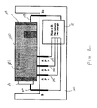
- FIG. 1 is an illustration of a battery having a charging indicating means, inserted into a detecting charger, in accordance with the invention.
- FIG. 2 is an illustration of a battery having a charging indicating means, inserted backwards into a detecting charger, illustrating a safety feature in accordance with the invention.
- FIG. 3 is an illustration of a prior art battery, inserted into a detecting charger in accordance with the invention.
- FIG. 4 is an illustration of an alternate battery, having a charging indicating means, inserted into a charger, in accordance with the invention
- the battery 100 is of standard construction, having both a cathode 103 and an anode 104 .
- the battery 100 is cylindrical in shape with a protruding cathode 103 at one end and a flat anode 104 at the opposite end.
- the battery housing is typically manufactured from an electrically conductive material, with the housing being electrically coupled to the anode 104 .
- a charging indicating means comprises a non-conductive label 101 having at least one aperture 102 .
- the aperture 105 or apertures, are configured such that a plurality of sensors 105 - 107 contact either the label 102 or the battery housing through the aperture 102 when the battery 100 is inserted into a charger 110 . While the aperture 102 may only partially circumscribe the battery 100 , it is preferable to have the aperture 102 completely circumscribe the battery 100 . This allows the sensors 105 - 107 to detect the presence of the aperture 102 regardless cylindrical rotation of the battery 100 .
- a charger 110 is used in this exemplary embodiment, an electronic device, like a phone, pager, personal data assistant, radio, phone, pager, MP3 player, compact disk player, or portable computer, having charging circuitry may operate as an alternative to the charger 110 .
- an electronic device like a phone, pager, personal data assistant, radio, phone, pager, MP3 player, compact disk player, or portable computer, having charging circuitry may operate as an alternative to the charger 110 .
- sensor 105 protrudes through the aperture 102 to connect with the housing of the battery 100 .
- the housing is electrically coupled to the anode 104 .
- a sensing means 111 which may comprise discrete analog detection circuitry, microprocessors, and the like, detects that sensor 105 is coupled to the anode contact 108 .
- sensors 106 and 107 detect open circuits. The sensing circuit 111 then decodes the sensed information to determine that a “first-type” battery 100 has been inserted.
- the sensing circuit 111 then instructs the charging circuit (not shown) to charge the battery 100 in accordance with an algorithm tailored to the first-type battery chemistry.
- an algorithm tailored to the first-type battery chemistry By using binary combinations of apertures, it is possible to detect different types of batteries simply through the plurality of sensors.
- the number of apertures, as well as their placement may be detected by way of hardware or software in the sensing circuit 111 .
- the software may comprise a look-up table corresponding to the different aperture scenarios.
- the invention also includes safety features. Referring now to FIG. 2, illustrated therein is the first-type battery 100 from FIG. 1. In FIG. 2, however, the battery 100 has been inserted into the charger 110 backwards. The anode 104 is unintentionally connected to the cathode contact 109 , and the cathode has been connected to the anode contact 108 . Charging the battery 100 in the reverse direction may lead to compromised battery performance.
- the sensors 105 - 107 all sense open circuits.
- the sensing circuit 111 interprets this to mean that no battery with a recognized aperture scheme has been inserted.
- the sensing circuit 111 thus instructs the charging circuit not to charge.
- FIG. 3 when a primary battery 300 is inserted in the charger 110 , the sensing circuit 111 , seeing no apertures, will instruct the charging circuit not to charge.
- the second-type battery 400 has a label 403 having two apertures 401 , 402 .
- the first aperture 401 corresponds to sensor 105 and the second corresponds to sensor 107 .
- the sensing circuit 111 detects that sensor 105 and 107 are both coupled to the anode 404 .
- the sensing circuit 111 thus instructs the charging circuit to charge the battery 400 with the second-type charging algorithm.
- the number, size and shape of the apertures are not limited to those as illustrated.
- the conductive material forming the cylindrical portion of the battery may be of any material as long as it is electrically-conductive and not prone to rusting.
- a steel sheet material plated with chromium or nickel is used.
- the label may be manufactured to include conductive traces.
- these conductive traces may then couple to a tab on the label that connects to the anode of the battery.
- these conductive traces may couple to a tab that connects to the battery housing.
- these conductive traces may connect to each other. In this particular configuration, the sensing circuit would detect shorts between particular conductive traces, as opposed to connections to the anode, to determine the particular battery configuration.
- the aperture system could be replaced with a bar-coding system, provided the charger were equipped with an optical sensing means to read the bar code.
- the label could be replaced with selective insulating coatings, inks or paint.
Abstract
Description
- 1. Technical Field
- This invention relates generally to rechargeable batteries, and more particularly to rechargeable batteries having charging indicating means to be sensed by a sensing means of an electronic device or charger.
- 2. Background Art
- Portable, battery-operated, electronic devices seem to be everywhere. From handheld games, to compact disc players, to radios, to personal data assistants, to phones, to pagers, it is becoming rare to encounter a person who does not carry at least one portable electronic device with them all the time. People carry the devices for entertainment, for organizational purposes, and for staying connected with others.
- It is the battery of the device that provides portability. In the days before batteries, the user of an electronic device had to remain tethered to an electrical outlet by way of a wire and power supply. With the advent of batteries, however, portability was born. The most popular batteries in use to day are the so-called “primary”, or single-use, batteries made by companies including Eveready, Duracell and Energizer. These batteries, usually of alkaline chemistry, are readily available in stores, including grocery and drug stores. Common sizes of these batteries include AAA, AA, C, 9 Volt and D. They are often cylindrical in shape and are easily replaceable in electronic devices. They may be used until the stored energy is depleted, and they are then discarded.
- While primary batteries are very convenient, they can become quite expensive for a user who constantly uses his electronic device. For example, a person who constantly listens to music on his portable stereo may have to replace as many as eight batteries on a weekly basis! This can become quite costly.
- To alleviate this problem, rechargeable battery manufacturers now make rechargeable batteries in the same size and shape as the primary batteries. In other words, one is now able to purchase a rechargeable battery that looks and works just like an alkaline, primary battery. When the rechargeable battery dies, the user simply recharges it as opposed to buying a new one. The rechargeable nature of these batteries makes them quite economical.
- The problem introduced by these rechargeable batteries is that they come in a variety of types and chemistries. Some may be nickel-based, while others are lithium-based. Additionally, within a particular chemistry family, some batteries may be designed to charge at high currents while others may only charge at lower currents. Improperly charging a battery may compromise its reliability. Thus, there is a need for a charger to be able to determine what type of battery is currently being used, and to adjust its charging voltage, current and procedure accordingly.
- One prior art solution to this problem is to design different types of rechargeable batteries with different shapes, or “form factors”. For example, a 1 amp battery may have contacts that are ½” apart, while a 10 amp battery may have contacts that are ¾” apart. The problem with this solution is that it does not allow for interchangeability with primary use batteries. If a rechargeable battery is to be substituted for an AA alkaline battery, it must be of the same size and shape.
- There is thus a need for a method and apparatus to determine the charging characteristics of a rechargeable battery.
- FIG. 1 is an illustration of a battery having a charging indicating means, inserted into a detecting charger, in accordance with the invention.
- FIG. 2 is an illustration of a battery having a charging indicating means, inserted backwards into a detecting charger, illustrating a safety feature in accordance with the invention.
- FIG. 3 is an illustration of a prior art battery, inserted into a detecting charger in accordance with the invention.
- FIG. 4 is an illustration of an alternate battery, having a charging indicating means, inserted into a charger, in accordance with the invention
- A preferred embodiment of the invention is now described in detail. Referring to the drawings, like numbers indicate like parts throughout the views. As used in the description herein and throughout the claims, the following terms take the meanings explicitly associated herein, unless the context clearly dictates otherwise: the meaning of “a,” “an,” and “the” includes plural reference, the meaning of “in” includes “in” and “on.”
- Referring now to FIG. 1, illustrated therein is a
rechargeable battery 100 having a charging indicating means in accordance with the invention. Thebattery 100 is of standard construction, having both acathode 103 and ananode 104. For example, if thebattery 100 is of the standard AA form factor, thebattery 100 is cylindrical in shape with aprotruding cathode 103 at one end and aflat anode 104 at the opposite end. The battery housing is typically manufactured from an electrically conductive material, with the housing being electrically coupled to theanode 104. - In a preferred embodiment, a charging indicating means comprises a
non-conductive label 101 having at least oneaperture 102. Theaperture 105, or apertures, are configured such that a plurality of sensors 105-107 contact either thelabel 102 or the battery housing through theaperture 102 when thebattery 100 is inserted into acharger 110. While theaperture 102 may only partially circumscribe thebattery 100, it is preferable to have theaperture 102 completely circumscribe thebattery 100. This allows the sensors 105-107 to detect the presence of theaperture 102 regardless cylindrical rotation of thebattery 100. Note also that while acharger 110 is used in this exemplary embodiment, an electronic device, like a phone, pager, personal data assistant, radio, phone, pager, MP3 player, compact disk player, or portable computer, having charging circuitry may operate as an alternative to thecharger 110. - In this exemplary embodiment,
sensor 105 protrudes through theaperture 102 to connect with the housing of thebattery 100. As stated above, in typical batteries, the housing is electrically coupled to theanode 104. This being the case, asensing means 111, which may comprise discrete analog detection circuitry, microprocessors, and the like, detects thatsensor 105 is coupled to theanode contact 108. As thelabel 101 is non-conductive,sensors sensing circuit 111 then decodes the sensed information to determine that a “first-type”battery 100 has been inserted. Thesensing circuit 111 then instructs the charging circuit (not shown) to charge thebattery 100 in accordance with an algorithm tailored to the first-type battery chemistry. By using binary combinations of apertures, it is possible to detect different types of batteries simply through the plurality of sensors. The number of apertures, as well as their placement may be detected by way of hardware or software in thesensing circuit 111. For example, the software may comprise a look-up table corresponding to the different aperture scenarios. - The invention also includes safety features. Referring now to FIG. 2, illustrated therein is the first-
type battery 100 from FIG. 1. In FIG. 2, however, thebattery 100 has been inserted into thecharger 110 backwards. Theanode 104 is unintentionally connected to thecathode contact 109, and the cathode has been connected to theanode contact 108. Charging thebattery 100 in the reverse direction may lead to compromised battery performance. - As the
label 101 is made of electrically insulating material however, the sensors 105-107 all sense open circuits. Thesensing circuit 111 interprets this to mean that no battery with a recognized aperture scheme has been inserted. Thesensing circuit 111 thus instructs the charging circuit not to charge. Similarly, in FIG. 3, when aprimary battery 300 is inserted in thecharger 110, thesensing circuit 111, seeing no apertures, will instruct the charging circuit not to charge. - Referring now to FIG. 4, illustrated therein is a “second-type”
battery 400. The second-type battery 400 has a label 403 having twoapertures first aperture 401 corresponds tosensor 105 and the second corresponds tosensor 107. When thisbattery 400 is inserted, thesensing circuit 111 detects thatsensor anode 404. Thesensing circuit 111 thus instructs the charging circuit to charge thebattery 400 with the second-type charging algorithm. - It will be readily understood by those skilled in the art that the number, size and shape of the apertures are not limited to those as illustrated. Further, the conductive material forming the cylindrical portion of the battery may be of any material as long as it is electrically-conductive and not prone to rusting. Preferably, a steel sheet material plated with chromium or nickel is used.
- In the event that the battery housing is not made of a conductive metal, the label may be manufactured to include conductive traces. In one embodiment, these conductive traces may then couple to a tab on the label that connects to the anode of the battery. In another embodiment, these conductive traces may couple to a tab that connects to the battery housing. In another embodiment, these conductive traces may connect to each other. In this particular configuration, the sensing circuit would detect shorts between particular conductive traces, as opposed to connections to the anode, to determine the particular battery configuration.
- While the preferred embodiments of the invention have been illustrated and described, it is clear that the invention is not so limited. Numerous modifications, changes, variations, substitutions, and equivalents will occur to those skilled in the art without departing from the spirit and scope of the present invention as defined by the following claims. For example, the aperture system could be replaced with a bar-coding system, provided the charger were equipped with an optical sensing means to read the bar code. Additionally, the label could be replaced with selective insulating coatings, inks or paint.
Claims (13)
Priority Applications (1)
| Application Number | Priority Date | Filing Date | Title |
|---|---|---|---|
| US10/122,946 US6897634B2 (en) | 2002-04-13 | 2002-04-13 | Rechargeable battery having charging indicating means |
Applications Claiming Priority (1)
| Application Number | Priority Date | Filing Date | Title |
|---|---|---|---|
| US10/122,946 US6897634B2 (en) | 2002-04-13 | 2002-04-13 | Rechargeable battery having charging indicating means |
Publications (2)
| Publication Number | Publication Date |
|---|---|
| US20030193312A1 true US20030193312A1 (en) | 2003-10-16 |
| US6897634B2 US6897634B2 (en) | 2005-05-24 |
Family
ID=28790656
Family Applications (1)
| Application Number | Title | Priority Date | Filing Date |
|---|---|---|---|
| US10/122,946 Expired - Lifetime US6897634B2 (en) | 2002-04-13 | 2002-04-13 | Rechargeable battery having charging indicating means |
Country Status (1)
| Country | Link |
|---|---|
| US (1) | US6897634B2 (en) |
Cited By (2)
| Publication number | Priority date | Publication date | Assignee | Title |
|---|---|---|---|---|
| US20060103347A1 (en) * | 2004-11-18 | 2006-05-18 | Shum King M | Battery charger |
| CN115149180A (en) * | 2021-03-30 | 2022-10-04 | 宏碁股份有限公司 | Electronic device and method for inhibiting battery expansion |
Families Citing this family (4)
| Publication number | Priority date | Publication date | Assignee | Title |
|---|---|---|---|---|
| JP3755591B2 (en) * | 2001-12-13 | 2006-03-15 | 日産自動車株式会社 | Battery and assembled battery using the same |
| US7491466B2 (en) * | 2005-06-03 | 2009-02-17 | Eveready Battery Company, Inc. | Battery with side terminal |
| US20120250237A1 (en) * | 2011-03-31 | 2012-10-04 | Joseph Skrivan | Interchangeable rechargeable battery system |
| US10629963B2 (en) * | 2015-12-24 | 2020-04-21 | Intel Corporation | Battery cell having a detection interface |
Citations (9)
| Publication number | Priority date | Publication date | Assignee | Title |
|---|---|---|---|---|
| US3930889A (en) * | 1974-07-22 | 1976-01-06 | Bell & Howell Company | Multiple source battery-powered apparatus |
| US4006396A (en) * | 1974-01-18 | 1977-02-01 | Motorola, Inc. | Universal battery charging apparatus |
| US4024557A (en) * | 1974-08-02 | 1977-05-17 | Fuji Photo Film Co., Ltd. | Film magazine having film speed indicating means |
| US4577145A (en) * | 1984-10-11 | 1986-03-18 | General Electric Company | Charging system having electromagnetic field means for distinguishing between primary and secondary batteries |
| US5331580A (en) * | 1989-01-31 | 1994-07-19 | Norand Corporation | Data capture system with communicating and recharging docking apparatus, and modular printer and hand-held data terminal means cooperable therewith |
| US5606238A (en) * | 1994-07-21 | 1997-02-25 | Rayovac Corporation | Discriminating battery charging system |
| US5843547A (en) * | 1995-03-16 | 1998-12-01 | Beiersdorf Ag | Multilayered label |
| US5868709A (en) * | 1996-05-28 | 1999-02-09 | Medfuse International, Inc. | Portable modular apparatus and method for destroying medical needles |
| US6020082A (en) * | 1998-02-19 | 2000-02-01 | Summit Microelectronics, Inc. | Integrated battery identification system and method for determination of battery type and voltage level operability |
-
2002
- 2002-04-13 US US10/122,946 patent/US6897634B2/en not_active Expired - Lifetime
Patent Citations (9)
| Publication number | Priority date | Publication date | Assignee | Title |
|---|---|---|---|---|
| US4006396A (en) * | 1974-01-18 | 1977-02-01 | Motorola, Inc. | Universal battery charging apparatus |
| US3930889A (en) * | 1974-07-22 | 1976-01-06 | Bell & Howell Company | Multiple source battery-powered apparatus |
| US4024557A (en) * | 1974-08-02 | 1977-05-17 | Fuji Photo Film Co., Ltd. | Film magazine having film speed indicating means |
| US4577145A (en) * | 1984-10-11 | 1986-03-18 | General Electric Company | Charging system having electromagnetic field means for distinguishing between primary and secondary batteries |
| US5331580A (en) * | 1989-01-31 | 1994-07-19 | Norand Corporation | Data capture system with communicating and recharging docking apparatus, and modular printer and hand-held data terminal means cooperable therewith |
| US5606238A (en) * | 1994-07-21 | 1997-02-25 | Rayovac Corporation | Discriminating battery charging system |
| US5843547A (en) * | 1995-03-16 | 1998-12-01 | Beiersdorf Ag | Multilayered label |
| US5868709A (en) * | 1996-05-28 | 1999-02-09 | Medfuse International, Inc. | Portable modular apparatus and method for destroying medical needles |
| US6020082A (en) * | 1998-02-19 | 2000-02-01 | Summit Microelectronics, Inc. | Integrated battery identification system and method for determination of battery type and voltage level operability |
Cited By (4)
| Publication number | Priority date | Publication date | Assignee | Title |
|---|---|---|---|---|
| US20060103347A1 (en) * | 2004-11-18 | 2006-05-18 | Shum King M | Battery charger |
| WO2006054909A1 (en) * | 2004-11-18 | 2006-05-26 | Jeckson Electric Company Limited | Battery charger |
| US7468596B2 (en) | 2004-11-18 | 2008-12-23 | Jeckson Electric Company Limited | Battery charger for various sizes of batteries with selection of appropriate charging power |
| CN115149180A (en) * | 2021-03-30 | 2022-10-04 | 宏碁股份有限公司 | Electronic device and method for inhibiting battery expansion |
Also Published As
| Publication number | Publication date |
|---|---|
| US6897634B2 (en) | 2005-05-24 |
Similar Documents
| Publication | Publication Date | Title |
|---|---|---|
| EP3535800B1 (en) | Reusable battery indicator with electrical lock and key | |
| AU2017355395B2 (en) | Single sided reusable battery indicator | |
| US20180123175A1 (en) | Dual sided reusable battery indicator | |
| JP7326153B2 (en) | Reusable battery indicator with lock/key mechanism | |
| US7491466B2 (en) | Battery with side terminal | |
| US20170062880A1 (en) | Battery including an on-cell indicator | |
| EP1805827A2 (en) | Multiple battery assembly for portable devices | |
| JPH09271144A (en) | Power supply identifying method, battery pack, and electronic device | |
| US20090108812A1 (en) | Contact module for rechargeable battery, mobile electronic device having the same contact module and method of preventing rechargeable battery from exploding using the same contact module | |
| US6897634B2 (en) | Rechargeable battery having charging indicating means | |
| EP0926798A1 (en) | Battery type determination for a radio telephone or battery charger | |
| JP2006331668A (en) | Secondary battery, charging device, battery discrimination seal, and seal sheet for battery discrimination | |
| US5457609A (en) | Charging contact for use with a battery powered electronic device | |
| EP1063715A3 (en) | Battery insulation and display panel protection and portable information terminal with battery insulation and display panel protection | |
| JP2009187720A (en) | Secondary battery pack, its charging control circuit, and electronic apparatus | |
| US5744930A (en) | Universal battery compartment | |
| JPH06237536A (en) | Battery-using system | |
| KR200213618Y1 (en) | Display Device Of Battery Charging Time | |
| JPH10321264A (en) | Charging battery, method and device for judging kind of charging battery, charging method and charging device, and electric and electronic equipment devices | |
| CN114583778A (en) | Device for charging brain-computer interface equipment and brain-computer interface system |
Legal Events
| Date | Code | Title | Description |
|---|---|---|---|
| AS | Assignment |
Owner name: MOTOROLA, INC., ILLINOIS Free format text: ASSIGNMENT OF ASSIGNORS INTEREST;ASSIGNOR:RAMSDEN, MARTIN;REEL/FRAME:012807/0386 Effective date: 20020412 |
|
| STCF | Information on status: patent grant |
Free format text: PATENTED CASE |
|
| FPAY | Fee payment |
Year of fee payment: 4 |
|
| AS | Assignment |
Owner name: MOTOROLA MOBILITY, INC, ILLINOIS Free format text: ASSIGNMENT OF ASSIGNORS INTEREST;ASSIGNOR:MOTOROLA, INC;REEL/FRAME:025673/0558 Effective date: 20100731 |
|
| AS | Assignment |
Owner name: MOTOROLA MOBILITY LLC, ILLINOIS Free format text: CHANGE OF NAME;ASSIGNOR:MOTOROLA MOBILITY, INC.;REEL/FRAME:029216/0282 Effective date: 20120622 |
|
| FPAY | Fee payment |
Year of fee payment: 8 |
|
| AS | Assignment |
Owner name: GOOGLE TECHNOLOGY HOLDINGS LLC, CALIFORNIA Free format text: ASSIGNMENT OF ASSIGNORS INTEREST;ASSIGNOR:MOTOROLA MOBILITY LLC;REEL/FRAME:034293/0138 Effective date: 20141028 |
|
| FPAY | Fee payment |
Year of fee payment: 12 |
|
| SULP | Surcharge for late payment |
Year of fee payment: 11 |
|
| AS | Assignment |
Owner name: AMPEREX TECHNOLOGY LIMITED, HONG KONG Free format text: ASSIGNMENT OF ASSIGNORS INTEREST;ASSIGNOR:GOOGLE TECHNOLOGY HOLDINGS LLC;REEL/FRAME:046392/0764 Effective date: 20180604 |