US20030192843A1 - System and apparatus for holding an item in storage - Google Patents
System and apparatus for holding an item in storage Download PDFInfo
- Publication number
- US20030192843A1 US20030192843A1 US10/445,699 US44569903A US2003192843A1 US 20030192843 A1 US20030192843 A1 US 20030192843A1 US 44569903 A US44569903 A US 44569903A US 2003192843 A1 US2003192843 A1 US 2003192843A1
- Authority
- US
- United States
- Prior art keywords
- strap
- shank
- item
- cantilevered
- slot
- Prior art date
- Legal status (The legal status is an assumption and is not a legal conclusion. Google has not performed a legal analysis and makes no representation as to the accuracy of the status listed.)
- Granted
Links
- 239000000463 material Substances 0.000 description 8
- 210000005069 ears Anatomy 0.000 description 6
- 229920000642 polymer Polymers 0.000 description 6
- 229910052751 metal Inorganic materials 0.000 description 4
- 239000002184 metal Substances 0.000 description 4
- 239000002585 base Substances 0.000 description 3
- 230000000994 depressogenic effect Effects 0.000 description 3
- 230000009977 dual effect Effects 0.000 description 3
- 238000010413 gardening Methods 0.000 description 3
- 238000010276 construction Methods 0.000 description 2
- 230000008878 coupling Effects 0.000 description 2
- 238000010168 coupling process Methods 0.000 description 2
- 238000005859 coupling reaction Methods 0.000 description 2
- -1 e.g. Substances 0.000 description 2
- 230000007794 irritation Effects 0.000 description 2
- 230000009471 action Effects 0.000 description 1
- 230000001154 acute effect Effects 0.000 description 1
- 229910052782 aluminium Inorganic materials 0.000 description 1
- XAGFODPZIPBFFR-UHFFFAOYSA-N aluminium Chemical compound [Al] XAGFODPZIPBFFR-UHFFFAOYSA-N 0.000 description 1
- VSCWAEJMTAWNJL-UHFFFAOYSA-K aluminum chloride Substances Cl[Al](Cl)Cl VSCWAEJMTAWNJL-UHFFFAOYSA-K 0.000 description 1
- 239000002131 composite material Substances 0.000 description 1
- 239000004035 construction material Substances 0.000 description 1
- 238000001125 extrusion Methods 0.000 description 1
- 238000002347 injection Methods 0.000 description 1
- 239000007924 injection Substances 0.000 description 1
- 238000003780 insertion Methods 0.000 description 1
- 230000037431 insertion Effects 0.000 description 1
- 230000003993 interaction Effects 0.000 description 1
- 238000012423 maintenance Methods 0.000 description 1
- 239000007769 metal material Substances 0.000 description 1
- 150000002739 metals Chemical class 0.000 description 1
- 230000004048 modification Effects 0.000 description 1
- 238000012986 modification Methods 0.000 description 1
- 230000008520 organization Effects 0.000 description 1
- 230000002093 peripheral effect Effects 0.000 description 1
- 229920003023 plastic Polymers 0.000 description 1
- 239000004033 plastic Substances 0.000 description 1
- 239000002861 polymer material Substances 0.000 description 1
- 229920000915 polyvinyl chloride Polymers 0.000 description 1
- 239000004800 polyvinyl chloride Substances 0.000 description 1
- 230000008439 repair process Effects 0.000 description 1
Images


Classifications
-
- A—HUMAN NECESSITIES
- A47—FURNITURE; DOMESTIC ARTICLES OR APPLIANCES; COFFEE MILLS; SPICE MILLS; SUCTION CLEANERS IN GENERAL
- A47F—SPECIAL FURNITURE, FITTINGS, OR ACCESSORIES FOR SHOPS, STOREHOUSES, BARS, RESTAURANTS OR THE LIKE; PAYING COUNTERS
- A47F5/00—Show stands, hangers, or shelves characterised by their constructional features
- A47F5/08—Show stands, hangers, or shelves characterised by their constructional features secured to the wall, ceiling, or the like; Wall-bracket display devices
- A47F5/0807—Display panels, grids or rods used for suspending merchandise or cards supporting articles; Movable brackets therefor
- A47F5/0815—Panel constructions with apertures for article supports, e.g. hooks
-
- A—HUMAN NECESSITIES
- A47—FURNITURE; DOMESTIC ARTICLES OR APPLIANCES; COFFEE MILLS; SPICE MILLS; SUCTION CLEANERS IN GENERAL
- A47B—TABLES; DESKS; OFFICE FURNITURE; CABINETS; DRAWERS; GENERAL DETAILS OF FURNITURE
- A47B96/00—Details of cabinets, racks or shelf units not covered by a single one of groups A47B43/00 - A47B95/00; General details of furniture
- A47B96/02—Shelves
- A47B96/027—Cantilever shelves
-
- A—HUMAN NECESSITIES
- A47—FURNITURE; DOMESTIC ARTICLES OR APPLIANCES; COFFEE MILLS; SPICE MILLS; SUCTION CLEANERS IN GENERAL
- A47B—TABLES; DESKS; OFFICE FURNITURE; CABINETS; DRAWERS; GENERAL DETAILS OF FURNITURE
- A47B96/00—Details of cabinets, racks or shelf units not covered by a single one of groups A47B43/00 - A47B95/00; General details of furniture
- A47B96/06—Brackets or similar supporting means for cabinets, racks or shelves
- A47B96/067—Horizontal rails as suspension means in a cantilever arrangement
-
- A—HUMAN NECESSITIES
- A47—FURNITURE; DOMESTIC ARTICLES OR APPLIANCES; COFFEE MILLS; SPICE MILLS; SUCTION CLEANERS IN GENERAL
- A47F—SPECIAL FURNITURE, FITTINGS, OR ACCESSORIES FOR SHOPS, STOREHOUSES, BARS, RESTAURANTS OR THE LIKE; PAYING COUNTERS
- A47F5/00—Show stands, hangers, or shelves characterised by their constructional features
- A47F5/08—Show stands, hangers, or shelves characterised by their constructional features secured to the wall, ceiling, or the like; Wall-bracket display devices
- A47F5/0807—Display panels, grids or rods used for suspending merchandise or cards supporting articles; Movable brackets therefor
- A47F5/0815—Panel constructions with apertures for article supports, e.g. hooks
- A47F5/0823—Article supports for peg-boards
-
- A—HUMAN NECESSITIES
- A47—FURNITURE; DOMESTIC ARTICLES OR APPLIANCES; COFFEE MILLS; SPICE MILLS; SUCTION CLEANERS IN GENERAL
- A47F—SPECIAL FURNITURE, FITTINGS, OR ACCESSORIES FOR SHOPS, STOREHOUSES, BARS, RESTAURANTS OR THE LIKE; PAYING COUNTERS
- A47F7/00—Show stands, hangers, or shelves, adapted for particular articles or materials
- A47F7/0021—Show stands, hangers, or shelves, adapted for particular articles or materials for long or non-stable articles, e.g. fishing rods, pencils, lipsticks or the like; Compartments or recesses as stabilising means
- A47F7/0028—Show stands, hangers, or shelves, adapted for particular articles or materials for long or non-stable articles, e.g. fishing rods, pencils, lipsticks or the like; Compartments or recesses as stabilising means with one compartment or recess for each article
-
- B—PERFORMING OPERATIONS; TRANSPORTING
- B25—HAND TOOLS; PORTABLE POWER-DRIVEN TOOLS; MANIPULATORS
- B25H—WORKSHOP EQUIPMENT, e.g. FOR MARKING-OUT WORK; STORAGE MEANS FOR WORKSHOPS
- B25H1/00—Work benches; Portable stands or supports for positioning portable tools or work to be operated on thereby
- B25H1/02—Work benches; Portable stands or supports for positioning portable tools or work to be operated on thereby of table type
-
- B—PERFORMING OPERATIONS; TRANSPORTING
- B25—HAND TOOLS; PORTABLE POWER-DRIVEN TOOLS; MANIPULATORS
- B25H—WORKSHOP EQUIPMENT, e.g. FOR MARKING-OUT WORK; STORAGE MEANS FOR WORKSHOPS
- B25H3/00—Storage means or arrangements for workshops facilitating access to, or handling of, work tools or instruments
- B25H3/04—Racks
-
- F—MECHANICAL ENGINEERING; LIGHTING; HEATING; WEAPONS; BLASTING
- F16—ENGINEERING ELEMENTS AND UNITS; GENERAL MEASURES FOR PRODUCING AND MAINTAINING EFFECTIVE FUNCTIONING OF MACHINES OR INSTALLATIONS; THERMAL INSULATION IN GENERAL
- F16B—DEVICES FOR FASTENING OR SECURING CONSTRUCTIONAL ELEMENTS OR MACHINE PARTS TOGETHER, e.g. NAILS, BOLTS, CIRCLIPS, CLAMPS, CLIPS OR WEDGES; JOINTS OR JOINTING
- F16B12/00—Jointing of furniture or the like, e.g. hidden from exterior
- F16B12/10—Jointing of furniture or the like, e.g. hidden from exterior using pegs, bolts, tenons, clamps, clips, or the like
- F16B12/12—Jointing of furniture or the like, e.g. hidden from exterior using pegs, bolts, tenons, clamps, clips, or the like for non-metal furniture parts, e.g. made of wood, of plastics
- F16B12/26—Jointing of furniture or the like, e.g. hidden from exterior using pegs, bolts, tenons, clamps, clips, or the like for non-metal furniture parts, e.g. made of wood, of plastics using snap-action elements
Definitions
- the present invention relates to storage and organizational systems and devices, and more particularly to storage and organizational systems and devices for storing home and garden tools or the like.
- pegboard or perforated panel systems are known for hanging articles in a vertical or horizontal orientation using pegboard hooks that are removably attached to a perforated panel. Shelving may also be provided on pegboards using the same or similar structures for securing and supporting the shelf to the pegboard.
- Prior art perforated panel systems typically comprise a pressed composite board material with regularly spaced circular perforations into which hooks may be inserted for the storage or display of tools, instruments, and other articles.
- a wide variety of useful fasteners for holding items to walls are also well known in the art.
- the available fasteners are much fewer in number, and those that are available have many severe drawbacks.
- Those who use pegboards are also familiar with the frustration and irritation associated with an insecure hook.
- Such fasteners often pull off the pegboard and get lost or damaged, especially when only one or two items are held.
- the typical pegboard fastener is a straight single or double bar, usually extending from about two inches to about six inches from the pegboard.
- a pegboard fastener of this type usually has a pair of bent rod-like offset hooked portions at its top. These offset hooked portions are inserted into horizontally adjacent holes, by a pivoting action, to situate the top tip of the hooked portions behind the wallboard while allowing the lower part of the fastener to rest against the front surface of the wallboard.
- an item holder for use with a perforated panel comprising a shank having a support arm extending outwardly from a first end and a catch located at a second end.
- the catch comprises a curved cantilevered strap projecting from the second end and having a stop tab located at a strap end positioned above, but spaced away from the second end.
- a system for supporting an item on a vertically oriented structure including a substantially planar board having a front surface, a rear surface, and a plurality of spaced perforations, where each perforation is defined by at least an internal top edge and an internal bottom edge of the board.
- An item holder is provided that comprises a shank having a support arm extending outwardly from a first end and a catch located at a second end.
- the catch comprises a curved cantilevered strap projecting from the second end and having a stop tab located at a strap end positioned above, but spaced away from the second end.
- a slot is defined through the underside of the cantilevered strap between a top portion of the shank and the second end of the cantilevered strap so that when the item holder is located within one of the plurality of perforations, the slot engages the internal bottom edge of the board.
- a tool holder in a further embodiment of the invention, includes at least one disk-shaped flexible member having an aperture.
- the flexible member comprises a plurality of fingers capable of resiliently deflecting to grip a portion of the tool when axially inserted therethrough in one direction so that the
- FIG. 1 is a perspective view of a storage system formed in accordance with the present invention
- FIG. 2 is a further embodiment of the storage system shown in FIG. 1;
- FIG. 3 is another variation of the storage system shown in FIGS. 1 and 2;
- FIG. 4 is a broken-away, perspective view of a perforated panel and item holder formed in accordance with the present invention
- FIG. 5 is a perspective view of a novel item holder formed in accordance with the present invention.
- FIG. 6 is a perspective view of a shelf-bracket system formed in accordance with the present invention.
- FIG. 7 is a perspective view of a shelf used in connection with the shelf-bracket of FIG. 6;
- FIG. 8 is an end view of the shelf shown in FIG. 7;
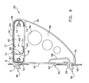
- FIG. 9 is an end view of the shelf and bracket shown in FIG. 5, as assembled to a perforated panel of the present invention.
- FIG. 10 is a novel hook adapted for mounting on a perforated panel or to a portion of a shelf in accordance with the present invention
- FIG. 11 is a perspective, partially exploded view of two hooks being inserted into a portion of a perforated panel in accordance with the present invention.
- FIG. 12 is a partially broken-away, perspective view of a shelf and shelf-bracket system assembled in accordance with the present invention, and having a hook and container assembled to an interior structure;
- FIG. 13 is an end view of the shelf, bracket, and hook assembly shown in FIG. 12;
- FIG. 14 is a perspective view of the item holder shown in FIG. 4, having a plurality of containers assembled to its underside;
- FIG. 15 is a perspective view of one of the containers shown in FIG. 14;
- FIG. 16 is an end view of the shelf, self-bracket and container assembly shown in FIG. 14;
- FIG. 17 is a perspective view of the item holder shown in FIG. 4, having a roll of material supported under the shelf and by the two shelf-brackets;
- FIG. 18 is a support rod used to support a roll of material as shown in FIG. 17;
- FIG. 19 is a perspective view, partially in phantom, of the rod and roll shown in FIG. 17, with the shelf and brackets removed for clarity of illustration;
- FIG. 20 shows another embodiment of the item holder shown in FIG. 4, and having a tool holder formed within the shelf;
- FIG. 21 is a perspective view of a tool holder of the type shown in FIG. 20;
- FIG. 22 is a cross-sectional view of the tool holder, as taken along lines 22 - 22 in FIG. 21;
- FIG. 23 is a cross-sectional view of the tool holder similar to FIG. 22, having a tool mounted within the tool holder;
- FIG. 24 is a perspective view of an alternative tool holder formed in accordance with the present invention.
- FIG. 25 is a perspective view of a receptacle and hook system formed in accordance with the present invention.
- FIG. 26 is a side elevational view of the receptacle and hook system shown in FIG. 25;
- FIG. 27 is a post bracket that may be mounted to a perforated panel formed in accordance with the present invention by use of the lock button shown in FIG. 29;
- FIG. 28 is a receptacle support bracket
- FIG. 29 is a perspective view of a lock-button used in accordance with the present invention.
- FIG. 30 is a perspective view of a receptacle support bracket as shown in FIG. 28, supporting a plurality of open faced receptacles;
- FIG. 31 is an angle shelf formed in accordance with the present invention.
- FIG. 32 and FIG. 33 are an item support and item receptacle, respectively, both formed so as to be mounted to the face of a perforated panel, as shown in FIGS. 1 - 4 .
- a new and improved storage and organization system 5 comprising a perforated panel 8 , storage cabinets 10 , bench 12 , drawers 13 , and shelves 15 .
- Storage system 5 is modular in construction such that various combinations of shelves, drawers, and cabinets may be arranged as needed or dictated by its position within a building, e.g., a residential garage, tool shed, or basement area.
- Storage cabinets 10 , bench 12 , drawers 13 , and shelves 15 are typically formed of common furniture construction materials, e.g., various metals, woods, or polymers.
- Perforated panel 8 comprises a planer sheet of material, preferably formed of a polymer or metal, and having a plurality of regularly shaped perforations 9 , disposed in a regular pattern throughout the panel. Perforations 9 are each preferably formed in perforated panel 8 so as to be defined by a circumferential edge, often forming a rectangular or square opening in panel 8 . Perforated panel 8 is typically about one quarter to one half of an inch thick, and in modules about two to three feet wide. Of course, it will be understood that perforated panel 8 may have various lengths and widths, depending upon the size of storage system 5 . Fixtures (not shown) for providing electric, gas, or pneumatic outlets may also be positioned anywhere within storage system 5 , as well as appliances, e.g., refrigerators or the like.
- perforated panel 8 is arranged above bench 12 so that a plurality of item holders 20 may be positioned on the front surface of perforated panel 8 .
- the term “item holder” will be used to represent a type of fixture that is attachable to perforated panel 8 by insertion of an element into at least one of perforations 9 and used to hold various implements, i.e., hand tools, garden tools, instruments, wires, cables, display objects (such as packages, blister display packs, vacuum display packs, loose hardware or household items, grocery items, department or variety store items, and shelves, pictures, wire frames, and the like.
- item holder 20 comprises a shelf 26 held to perforated panel 8 , via shelf-brackets 30 .
- shelf-brackets 30 comprise a circumferential flange 31 having a top surface 32 , an outward face 36 , a bottom 34 , and an inner wall 35 .
- a lower web 38 is positioned between outward face 36 , bottom 34 , and inner wall 35 .
- Shelf-brackets 30 are preferably formed from an injection moldable polymer, but may also be formed from metal or other materials as desired.
- a plurality of openings 39 are defined through lower web 38 , often having varying diameters.
- An upper web 40 is positioned between top surface 32 and lower web 38 .
- a ledge 44 projects outwardly in circumferential surrounding relation to upper web 40 , thereby separating upper web 40 from lower web 38 and forming a receptacle portion for receiving an end edge of shelf 26 .
- a plurality of holes 46 are defined through upper web 40 .
- An upper panel-catch 48 and a lower panel-catch 49 project outwardly from the outer surface of inner wall 35 .
- Each of upper panel-catch 48 and lower panel-catch 49 comprise a substantially “hook” shape having a lock-tab 52 projecting toward the outer surface of inner wall 35 .
- a lock-release latch 50 Adjacent to lower panel-catch 49 is a lock-release latch 50 , including a lock-release cantilever 54 that projects from an end of inner wall 35 .
- a lockrelease tab 56 is positioned at the free end of lock-release cantilever 54 .
- a recessed wall 58 is positioned in spaced relation to lock-release cantilever 54 , so as to provide a recess within shelf-bracket 30 into which lock-release cantilever 54 may deflect.
- shelf 26 comprises end edges 60 , a top support surface 63 , a nose 65 , a panel flange 67 , and a semi-tubular receptacle 68 . More particularly, shelf 26 comprises a substantially channel shape, and may be formed by extrusion of a suitable metal or polymer, e.g., aluminum or polyvinyl chloride. Top support surface 63 separates nose 65 from panel flange 67 such that each forms a longitudinal edge of shelf 26 . Nose 65 and panel flange 67 are arranged in spaced parallel relation to one another.
- Receptacle 68 projects downwardly from the underside of top support surface 63 in spaced relation to the inner surfaces of nose 65 and panel flange 67 .
- a slot 69 is defined between an upper flange 70 that projects outwardly from the underside of shelf 26 , and a lower flange 71 that projects upwardly from an end of a wall 72 that is arranged in spaced relation to upper flange 70 so as to define receptacle 68 .
- Slot 69 extends longitudinally along the length of receptacle 68 , with upper flange 70 and lower flange 71 typically arranged in coplanar spaced relation to one another.
- item holder 20 is assembled to perforated panel 8 in the following manner.
- a shelf-bracket 30 is positioned on each end of shelf 26 so that upper web 40 is disposed in aligned confronting relation to an end edge 60 of shelf 26 .
- face 36 of each shelf-bracket 30 extends downwardly from nose 65 of shelf 26 .
- Each shelf-bracket 30 is then moved toward its respective end edge 60 , until shelf 26 engages upper web 40 .
- screws may be inserted through holes 46 in upper web 40 and into semi-circular receptacles 73 so as to retain shelf-brackets 30 to shelf 26 .
- each panel-catch 48 , 49 of each shelf-bracket 30 is positioned in coaxial aligned relation with a corresponding set of four perforations 9 in perforated panel 8 .
- lock-release tab 56 is positioned in confronting relation to the front surface of perforated panel 8 , directly above the perforation 9 with which its corresponding lower panel-catch 49 is aligned.
- item holder 20 is moved toward perforated panel 8 until upper panel-catches 48 enter, pass through, and occupy their respective perforation 9 .
- lower panel-catches 49 enter, pass through, and occupy their respective perforations 9 .
- lock-release tab 56 engages the front surface of perforated panel 8 directly adjacent to the perforation 9 that is occupied by lower panel-catch 49 .
- item holder 20 is moved toward perforated panel 8 until the outer surface of inner wall 35 engages the outer surface of perforated panel 8 .
- panel-catches 48 and 49 are fully inserted within perforations 9 , and lock-release latch 50 is deflected inwardly, toward recessed wall 58 of shelf-bracket 30 .
- Item holder 20 is then moved downwardly, so that lock-tabs 52 move across the edge of perforated panel 8 that defines perforation 9 , and into engagement with the rear surface of perforated panel 8 (as shown in FIG. 9).
- lock-release tab 56 of lock-release latch 50 slides along the front surface of perforated panel 8 , and across the peripheral edge of perforation 9 into which lower panel-catch 49 has been previously inserted.
- lock-release cantilever 54 is released so as to move outwardly, away from recessed wall 58 , such that lock-release tab 56 slides along the edge of perforated panel 8 that defines perforation 9 , so as to secure shelf-bracket 30 in locked engagement with perforated panel 8 .
- both shelf-brackets 30 may be slid outwardly, disengaging lock tabs 52 , so that item holder 20 may be pulled from its position on perforated panel 8 .
- Item holder 20 may be used as a conventional shelf with various items being placed on top support surface 63 . However, items may also be held beneath shelf 26 , or on hooks 80 that are directly supported by perforated panel 8 , so as to advantageously store additional items.
- hook 80 comprises a shank 82 , a support arm 84 , and a catch 86 . More particularly, shank 82 and support arm 84 form a conventional hook of the type known for hanging tools and other items. Hook 80 may be formed from any of the well known polymer or metal materials that are known to exhibit good spring characteristics.
- Catch 86 comprises a stop tab 88 and a cantilevered strap 92 that are located adjacent to a top portion 87 of shank 82 .
- Stop 88 includes a nose 93 , a pair of inclined surfaces forming a ramp 94 , and a shoulder surface 95 so as to form a wedge-shaped tab.
- a first end 96 of cantilevered strap 92 projects outwardly from shoulder surface 95 and a second end 97 of cantilevered strap 92 projects outwardly from top portion 87 of shank 82 , so that cantilevered strap 92 comprises a curved profile.
- Cantilevered strap 92 may have a variety of crosssectional shapes, e.g., rectangular, circular, elliptical, etc., so long as a fully elastic spring is created by the structure of the strap.
- a transverse slot 98 is defined through the underside of cantilevered strap 92 between top portion 87 of shank 82 and second end 97 of cantilevered strap 92 . Slot 98 is sized and shaped to accept a portion of lower flange 71 of receptacle 68 .
- Hook 80 may be assembled to any perforation 9 within perforated panel 8 , as shown in FIG. 11. More particularly, hook 80 is arranged adjacent to perforated panel 8 , such that support arm 84 is directed away from the outer surface of perforated panel 8 and cantilevered strap 92 is arranged in coaxially aligned, confronting relation to a perforation 9 (FIG. 11). Ramp 94 of stop 88 is then depressed, deflecting cantilevered strap 92 such that the underside of stop 88 moves toward top portion 87 of shank 82 .
- hook 80 is moved toward perforation 9 until shoulder surface 95 engages the front surface of perforated panel 8 that surrounds perforation 9 , and the edge of perforated panel 8 that defines a portion of perforation 9 engages slot 98 of catch 86 .
- Pressure is then released from ramp 94 so as to allow cantilevered strap 92 to spring back towards its original, undeflected position, and thereby engage the internal edges of perforated panel 8 that define perforation 9 .
- hook 80 may be withdrawn from perforated panel 8 .
- hook 80 may also be assembled to receptacle 68 of shelf 26 in the following manner.
- Hook 80 is arranged adjacent to receptacle 68 such that support arm 84 is directed away from the outer surface of perforated panel 8 and cantilevered strap 92 is arranged in coaxially aligned, confronting relation to slot 69 .
- Ramp 94 of stop 88 is then depressed, deflecting cantilevered strap 92 such that the underside of stop 88 moves toward the top portion of shank 82 .
- hook 80 is moved toward slot 69 until shoulder surface 95 engages the front surface of upper flange 70 and the upper edge of lower flange 71 engages slot 98 .
- a container 100 may also be positioned on the underside of item holder 20 . More particularly, container 100 comprises an open-ended receptacle having a front cantilevered latch 105 a and a rear cantilevered latch 105 b . Each cantilevered latch 105 a , 105 b comprises a shoulder 106 , and a pair of spaced apart cam ears 107 . Each cam ear 107 also includes a front ramp 108 . Adjacent to each cam ear 107 , on container 100 are upwardly projecting stops 109 . Container 100 may assembled to the underside of shelf 26 through the interaction of cantilevered latches 105 a , 10 b with portions of shelf 26 .
- a roll of material e.g., paper towels, wrapping paper, plastic wrap, etc.
- a rod 118 comprises a pair of supports 120 positioned at each end. Rod 118 is inserted through the roll of material, and supports 120 are inserted into support openings 39 within lower web 38 of each shelf-bracket 30 .
- Item holder 20 may also comprise a shelf 126 including a hand tool holder 130 that supports hand tools, e.g., screwdrivers, nut drivers, awls, pliers, hand socket wrenches, etc., in an upright, vertical orientation, so as to improve the esthetics and accessibility of the tools (FIGS. 20 - 24 ).
- hand tools e.g., screwdrivers, nut drivers, awls, pliers, hand socket wrenches, etc.
- tool holder 130 is positioned within shelf 126 , and comprises a top 132 , a bottom 134 , and a plurality of tubes 138 that are positioned between top 132 and bottom 134 .
- a pair of disk-shaped flexible tool support members 140 are positioned in top 132 and bottom 134 , and within each tube 138 .
- Each disk-shaped flexible tool support member 140 comprises a plurality of resilient fingers 141 , with each finger often comprising a triangular shape having a tip 142 and a base 143 .
- Each finger 141 is oriented so that its tip 142 is directed radially inwardly toward the central axis of tube 138 .
- Fingers 141 are normally arranged in coplanar relation to one another.
- a radially extending space or gap 144 is defined between each finger 141 , along their respective lengths, with tips 142 positioned in spaced relation to one another and in coaxial relation to a longitudinal axis of each tube 138 .
- a central aperture 145 is defined by tips 142 .
- a tool e.g., screwdriver 129 in FIGS. 4 and 23
- its shaft enters central opening 145 and engages tips 142 of fingers 141 .
- Fingers 141 deflect downwardly while at the same time exerting a force against the shaft sufficient to hold the tool between fingers 141 so that the tool does not wobble or flop over, and is therefore in an upright position, readily accessible.
- fingers 141 do not necessarily have to be arranged in a circular pattern, but may also comprise, e.g., an oval 146 , as shown in FIG. 24.
- numerous holders 130 may be positioned within shelf 126 , as needed.
- shelf 126 is assembled to shelf-brackets 130 and perforated panel 8 in the same way that shelf 26 is assembled to shelf-brackets 30 and perforated panel 8 .
- Bracket receptacle 147 that is substantially identical to receptacle 68 may be formed as a stand-alone device and appended from perforated panel 8 (FIGS. 25 and 26).
- Bracket receptacle 147 includes a slot 69 that is defined between an upper flange 70 and a lower flange 71 that each project outwardly from a base plate 151 .
- Base plate 151 may be supported upon perforated panel 8 by fasteners that engage perforations 9 , e.g., by catch 86 .
- Slot 69 extends longitudinally along the length of bracket receptacle 147 , with upper flange 70 and lower flange 71 typically arranged in coplanar spaced relation to one another.
- Hook 80 may also be assembled to receptacle 147 in the following manner. Hook 80 is arranged adjacent to bracket receptacle 147 such that support arm 84 is directed away from the outer surface of perforated panel 8 and cantilevered strap 92 is arranged in coaxially aligned, confronting relation to slot 69 . Ramp 94 of stop 88 is then depressed, deflecting cantilevered strap 92 such that the underside of stop 88 moves toward the top portion of shank 82 . Once in this position, hook 80 is moved toward slot 69 until shoulder surface 95 engages the front surface of upper flange 70 and the upper edge of lower flange 71 engages slot 98 .
- lock buttons 150 comprise a rectilinear cam 154 , a face plate 156 , and a tool receptacle 158 .
- Lock buttons 150 are sized, shaped, and arranged so that cam 154 may be slidingly received within a perforation 9 .
- cam 54 is first positioned in coaxial-aligned relation with a correspondingly shaped perforation 19 , positioned within post bracket 148 or receptacle bracket 149 .
- Both lock button 150 , post bracket 148 or receptacle bracket 149 are then positioned in engaged relation with perforated panel 8 , such that perforations 9 and 19 are coaxially aligned.
- lock button 150 is inserted through perforations 9 and 19 , with rectilinear cam 154 oriented so as to correspond with the profile of perforations 9 and 19 .
- face plate 156 is rotated, clockwise or counter-clockwise, by a tool inserted within tool mount 158 , such that cam 154 rotates out of alignment with the internal edges of perforated panel 8 that define perforations 9 and 19 .
- Post bracket 148 may have a plurality of outwardly projecting posts, hooks, clamps, or a magnetic strip 160 (shown in FIG. 4 in connection with shelf 26 ) for hanging various tools or materials, as needed. Likewise, such means for hanging tools may also be combined with shelves 26 or 126 , as desired.
- Receptacle bracket 149 includes a hook 162 that is adapted to engage a corresponding hook on an open faced receptacle 168 , that may be hung from receptacle bracket 148 .
- an angled shelf 170 may be assembled to perforated panel 8 via lock buttons 150 in a similar manner (FIG. 28).
- dual hook support 180 comprises a pair of hooks 184 that project outwardly from a back plate 186 .
- a tab latch 187 projects downwardly from a bottom portion of back plate 186
- a latch cantilever 188 projects from a top of back plate 186 .
- Dual hook 180 is assembled to perforated panel 8 by first inserting tab latch 187 into a perforation 9 of perforated panel 8 .
- Back plate 186 is then pivoted about tab latch 187 until cantilever latch 188 is deflected into engagement with a corresponding perforation 9 in perforated panel 8 .
- Basket 182 is formed from a resilient polymer, and comprises a curved shell 183 having lower support tabs 190 projecting downwardly from a bottom surface and latch ears 192 projecting outwardly from the upper corner portions.
- latch ears 192 are deflected inwardly by pressing on the side walls of basket 182 , while tabs 190 are inserted into respective holes 9 .
- Basket 182 is then pivoted on tabs 190 until latch ears 192 are received within corresponding perforations 9 . Once latch ears 192 are inserted within perforations 9 , basket 182 is released, allowing latch ears 192 to spring outwardly into engagement with perforated panel 8 .
Abstract
Description
- This application is a continuation-in-part application of co-pending U.S. application Ser. No. 10/054,835, filed on Jan. 23, 2002.
- The present invention relates to storage and organizational systems and devices, and more particularly to storage and organizational systems and devices for storing home and garden tools or the like.
- In modern American suburbia, the garage has become the storage receptacle for a myriad of items that are necessary for work and recreation. The need for this storage space has become so acute that many suburban dwellings contain a 3-car garage even though the occupants own only two vehicles. Although, in many instances a recreational vehicle or boat occupies the third bay; in most cases, that extra space is utilized for storage and as a work area. Items such as sports equipment, gardening implements, and work shop related items, e.g., screwdrivers, hammers, wrenches, hand and power tools, and other implements for home, vehicle, or garden repair and maintenance are generally stored in the garage.
- There are a number of systems for storing relatively small and lightweight articles known in the art. For example, pegboard or perforated panel systems are known for hanging articles in a vertical or horizontal orientation using pegboard hooks that are removably attached to a perforated panel. Shelving may also be provided on pegboards using the same or similar structures for securing and supporting the shelf to the pegboard. Prior art perforated panel systems (known as “pegboards”) typically comprise a pressed composite board material with regularly spaced circular perforations into which hooks may be inserted for the storage or display of tools, instruments, and other articles. Changing the locations of the stored articles requires that the hooks or shelf-supports be removed completely from their respective supporting holes in the pegboard, and then reinserted into other holes. After a period of use, the holes tend to become worn and enlarged, and eventually become unable to retain the hooks. Also, the hooks are easily misplaced or lost. These pegboard systems are also aesthetically unattractive, especially after many years of use.
- A wide variety of useful fasteners for holding items to walls are also well known in the art. When attaching items to a perforated wall or pegboard, however, the available fasteners are much fewer in number, and those that are available have many severe drawbacks. Those who use pegboards are also familiar with the frustration and irritation associated with an insecure hook. Such fasteners often pull off the pegboard and get lost or damaged, especially when only one or two items are held. The typical pegboard fastener is a straight single or double bar, usually extending from about two inches to about six inches from the pegboard. A pegboard fastener of this type usually has a pair of bent rod-like offset hooked portions at its top. These offset hooked portions are inserted into horizontally adjacent holes, by a pivoting action, to situate the top tip of the hooked portions behind the wallboard while allowing the lower part of the fastener to rest against the front surface of the wallboard.
- While the use of a pair of hooked portions may inhibit rotation of the pegboard fastener, it does not avoid the frustration experienced when the pegboard fastener itself is pulled off the pegboard along with the item being removed. Those who encounter such fasteners or holders for hanging items experience frustration and irritation when attempting to remove the item from the fastener, since the bottom portion of the fastener is easily pulled away from the wall surface, i.e., there is no provision for fixing it to the pegboard.
- Therefore, it would be advantageous to have a storage system which allowed ease of accessibility to tools, such as gardening implements, while maximizing the use of garage space, in an aesthetically satisfying manner. It would also be advantageous to have a storage system that could be mounted directly to the walls of a typical garage or tool shed, thereby allowing effective use of available space while removing sports equipment, gardening implements, and work shop related items from the floor space of the garage or a tool shed.
- In one embodiment of the invention, an item holder for use with a perforated panel is provided comprising a shank having a support arm extending outwardly from a first end and a catch located at a second end. The catch comprises a curved cantilevered strap projecting from the second end and having a stop tab located at a strap end positioned above, but spaced away from the second end.
- In another embodiment, a system for supporting an item on a vertically oriented structure is provided including a substantially planar board having a front surface, a rear surface, and a plurality of spaced perforations, where each perforation is defined by at least an internal top edge and an internal bottom edge of the board. An item holder is provided that comprises a shank having a support arm extending outwardly from a first end and a catch located at a second end. The catch comprises a curved cantilevered strap projecting from the second end and having a stop tab located at a strap end positioned above, but spaced away from the second end. A slot is defined through the underside of the cantilevered strap between a top portion of the shank and the second end of the cantilevered strap so that when the item holder is located within one of the plurality of perforations, the slot engages the internal bottom edge of the board.
- In a further embodiment of the invention, a tool holder is provided that includes at least one disk-shaped flexible member having an aperture. The flexible member comprises a plurality of fingers capable of resiliently deflecting to grip a portion of the tool when axially inserted therethrough in one direction so that the
- tool is held in an upright position by the flexible member.
- These and other features and advantages of the present invention will be more fully disclosed in, or rendered obvious by, the following detailed description of the preferred embodiments of the invention, which are to be considered together with the accompanying drawings wherein like numbers refer to like parts and further wherein:
- FIG. 1 is a perspective view of a storage system formed in accordance with the present invention;
- FIG. 2 is a further embodiment of the storage system shown in FIG. 1;
- FIG. 3 is another variation of the storage system shown in FIGS. 1 and 2;
- FIG. 4 is a broken-away, perspective view of a perforated panel and item holder formed in accordance with the present invention;
- FIG. 5 is a perspective view of a novel item holder formed in accordance with the present invention;
- FIG. 6 is a perspective view of a shelf-bracket system formed in accordance with the present invention;
- FIG. 7 is a perspective view of a shelf used in connection with the shelf-bracket of FIG. 6;
- FIG. 8 is an end view of the shelf shown in FIG. 7;
- FIG. 9 is an end view of the shelf and bracket shown in FIG. 5, as assembled to a perforated panel of the present invention;
- FIG. 10 is a novel hook adapted for mounting on a perforated panel or to a portion of a shelf in accordance with the present invention;
- FIG. 11 is a perspective, partially exploded view of two hooks being inserted into a portion of a perforated panel in accordance with the present invention;
- FIG. 12 is a partially broken-away, perspective view of a shelf and shelf-bracket system assembled in accordance with the present invention, and having a hook and container assembled to an interior structure;
- FIG. 13 is an end view of the shelf, bracket, and hook assembly shown in FIG. 12;
- FIG. 14 is a perspective view of the item holder shown in FIG. 4, having a plurality of containers assembled to its underside;
- FIG. 15 is a perspective view of one of the containers shown in FIG. 14;
- FIG. 16 is an end view of the shelf, self-bracket and container assembly shown in FIG. 14;
- FIG. 17 is a perspective view of the item holder shown in FIG. 4, having a roll of material supported under the shelf and by the two shelf-brackets;
- FIG. 18 is a support rod used to support a roll of material as shown in FIG. 17;
- FIG. 19 is a perspective view, partially in phantom, of the rod and roll shown in FIG. 17, with the shelf and brackets removed for clarity of illustration;
- FIG. 20 shows another embodiment of the item holder shown in FIG. 4, and having a tool holder formed within the shelf;
- FIG. 21 is a perspective view of a tool holder of the type shown in FIG. 20;
- FIG. 22 is a cross-sectional view of the tool holder, as taken along lines 22-22 in FIG. 21;
- FIG. 23 is a cross-sectional view of the tool holder similar to FIG. 22, having a tool mounted within the tool holder;
- FIG. 24 is a perspective view of an alternative tool holder formed in accordance with the present invention;
- FIG. 25 is a perspective view of a receptacle and hook system formed in accordance with the present invention;
- FIG. 26 is a side elevational view of the receptacle and hook system shown in FIG. 25;
- FIG. 27 is a post bracket that may be mounted to a perforated panel formed in accordance with the present invention by use of the lock button shown in FIG. 29;
- FIG. 28 is a receptacle support bracket;
- FIG. 29 is a perspective view of a lock-button used in accordance with the present invention;
- FIG. 30 is a perspective view of a receptacle support bracket as shown in FIG. 28, supporting a plurality of open faced receptacles;
- FIG. 31 is an angle shelf formed in accordance with the present invention;
- FIG. 32 and FIG. 33 are an item support and item receptacle, respectively, both formed so as to be mounted to the face of a perforated panel, as shown in FIGS. 1-4.
- This description of preferred embodiments is intended to be read in connection with the accompanying drawings, which are to be considered part of the entire written description of this invention. The drawing figures are not necessarily to scale and certain features of the invention may be shown exaggerated in scale or in somewhat schematic form in the interest of clarity and conciseness. In the description, relative terms such as “horizontal,” “vertical,” “up,” “down,” “top” and “bottom” as well as derivatives thereof (e.g., “horizontally,” “downwardly,” “upwardly,” etc.) should be construed to refer to the orientation as then described or as shown in the drawing figure under discussion. These relative terms are for convenience of description and normally are not intended to require a particular orientation. Terms including “inwardly” versus “outwardly,” “longitudinal” versus “lateral” and the like are to be interpreted relative to one another or relative to an axis of elongation, or an axis or center of rotation, as appropriate. Terms concerning attachments, coupling and the like, such as “connected” and “interconnected,” refer to a relationship wherein structures are secured or attached to one another either directly or indirectly through intervening structures, as well as both movable or rigid attachments or relationships, unless expressly described otherwise. The term “operatively connected” is such an attachment, coupling or connection that allows the pertinent structures to operate as intended by virtue of that relationship. In the claims, means-plusfunction clauses are intended to cover the structures described, suggested, or rendered obvious by the written description or drawings for performing the recited function, including not only structural equivalents but also equivalent structures.
- Referring to FIGS. 1-3, a new and improved storage and
organization system 5 is provided comprising aperforated panel 8,storage cabinets 10,bench 12,drawers 13, andshelves 15.Storage system 5 is modular in construction such that various combinations of shelves, drawers, and cabinets may be arranged as needed or dictated by its position within a building, e.g., a residential garage, tool shed, or basement area.Storage cabinets 10,bench 12,drawers 13, andshelves 15 are typically formed of common furniture construction materials, e.g., various metals, woods, or polymers.Perforated panel 8 comprises a planer sheet of material, preferably formed of a polymer or metal, and having a plurality of regularly shapedperforations 9, disposed in a regular pattern throughout the panel.Perforations 9 are each preferably formed inperforated panel 8 so as to be defined by a circumferential edge, often forming a rectangular or square opening inpanel 8.Perforated panel 8 is typically about one quarter to one half of an inch thick, and in modules about two to three feet wide. Of course, it will be understood thatperforated panel 8 may have various lengths and widths, depending upon the size ofstorage system 5. Fixtures (not shown) for providing electric, gas, or pneumatic outlets may also be positioned anywhere withinstorage system 5, as well as appliances, e.g., refrigerators or the like. - Referring to FIGS. 1-4,
perforated panel 8 is arranged abovebench 12 so that a plurality ofitem holders 20 may be positioned on the front surface ofperforated panel 8. For convenience in this specification, the term “item holder” will be used to represent a type of fixture that is attachable toperforated panel 8 by insertion of an element into at least one ofperforations 9 and used to hold various implements, i.e., hand tools, garden tools, instruments, wires, cables, display objects (such as packages, blister display packs, vacuum display packs, loose hardware or household items, grocery items, department or variety store items, and shelves, pictures, wire frames, and the like. In one preferred embodiment,item holder 20 comprises ashelf 26 held toperforated panel 8, via shelf-brackets 30. - Referring to FIGS. 5 and 6, shelf-
brackets 30 comprise acircumferential flange 31 having atop surface 32, anoutward face 36, a bottom 34, and aninner wall 35. Alower web 38 is positioned betweenoutward face 36, bottom 34, andinner wall 35. Shelf-brackets 30 are preferably formed from an injection moldable polymer, but may also be formed from metal or other materials as desired. A plurality ofopenings 39 are defined throughlower web 38, often having varying diameters. Anupper web 40 is positioned betweentop surface 32 andlower web 38. Aledge 44 projects outwardly in circumferential surrounding relation toupper web 40, thereby separatingupper web 40 fromlower web 38 and forming a receptacle portion for receiving an end edge ofshelf 26. A plurality ofholes 46 are defined throughupper web 40. An upper panel-catch 48 and a lower panel-catch 49 project outwardly from the outer surface ofinner wall 35. Each of upper panel-catch 48 and lower panel-catch 49 comprise a substantially “hook” shape having a lock-tab 52 projecting toward the outer surface ofinner wall 35. - Adjacent to lower panel-
catch 49 is a lock-release latch 50, including a lock-release cantilever 54 that projects from an end ofinner wall 35. Alockrelease tab 56 is positioned at the free end of lock-release cantilever 54. A recessedwall 58 is positioned in spaced relation to lock-release cantilever 54, so as to provide a recess within shelf-bracket 30 into which lock-release cantilever 54 may deflect. - Referring to FIGS. 7 and 8,
shelf 26 comprises end edges 60, atop support surface 63, anose 65, apanel flange 67, and asemi-tubular receptacle 68. More particularly,shelf 26 comprises a substantially channel shape, and may be formed by extrusion of a suitable metal or polymer, e.g., aluminum or polyvinyl chloride.Top support surface 63 separatesnose 65 frompanel flange 67 such that each forms a longitudinal edge ofshelf 26.Nose 65 andpanel flange 67 are arranged in spaced parallel relation to one another.Receptacle 68 projects downwardly from the underside oftop support surface 63 in spaced relation to the inner surfaces ofnose 65 andpanel flange 67. Aslot 69 is defined between anupper flange 70 that projects outwardly from the underside ofshelf 26, and alower flange 71 that projects upwardly from an end of awall 72 that is arranged in spaced relation toupper flange 70 so as to definereceptacle 68.Slot 69 extends longitudinally along the length ofreceptacle 68, withupper flange 70 andlower flange 71 typically arranged in coplanar spaced relation to one another. - Referring to FIG. 9,
item holder 20 is assembled toperforated panel 8 in the following manner. A shelf-bracket 30 is positioned on each end ofshelf 26 so thatupper web 40 is disposed in aligned confronting relation to anend edge 60 ofshelf 26. In this position, face 36 of each shelf-bracket 30 extends downwardly fromnose 65 ofshelf 26. Each shelf-bracket 30 is then moved toward itsrespective end edge 60, untilshelf 26 engagesupper web 40. Once assembled, screws (not shown) may be inserted throughholes 46 inupper web 40 and intosemi-circular receptacles 73 so as to retain shelf-brackets 30 toshelf 26. - Once
item holder 20 is fully assembled, it may be positioned anywhere onperforated panel 8 in the following manner. Each panel-catch bracket 30 is positioned in coaxial aligned relation with a corresponding set of fourperforations 9 inperforated panel 8. In this position, lock-release tab 56 is positioned in confronting relation to the front surface ofperforated panel 8, directly above theperforation 9 with which its corresponding lower panel-catch 49 is aligned. Once in this position,item holder 20 is moved towardperforated panel 8 until upper panel-catches 48 enter, pass through, and occupy theirrespective perforation 9. As this occurs, lower panel-catches 49 enter, pass through, and occupy theirrespective perforations 9. At the same time, lock-release tab 56 engages the front surface ofperforated panel 8 directly adjacent to theperforation 9 that is occupied by lower panel-catch 49. - Once in this position,
item holder 20 is moved towardperforated panel 8 until the outer surface ofinner wall 35 engages the outer surface ofperforated panel 8. In this position, panel-catches perforations 9, and lock-release latch 50 is deflected inwardly, toward recessedwall 58 of shelf-bracket 30.Item holder 20 is then moved downwardly, so that lock-tabs 52 move across the edge ofperforated panel 8 that definesperforation 9, and into engagement with the rear surface of perforated panel 8 (as shown in FIG. 9). As this occurs, lock-release tab 56 of lock-release latch 50 slides along the front surface ofperforated panel 8, and across the peripheral edge ofperforation 9 into which lower panel-catch 49 has been previously inserted. As this occurs, lock-release cantilever 54 is released so as to move outwardly, away from recessedwall 58, such that lock-release tab 56 slides along the edge ofperforated panel 8 that definesperforation 9, so as to secure shelf-bracket 30 in locked engagement withperforated panel 8. In order to removeitem holder 20, it is necessary only to deflect lock-release cantilever 54 inwardly, toward recessedwall 58 and moveitem holder 20 upwardly relative toperforated panel 8. In this way, when lock-release tabs 56 disengage from theirrespective perforations 9, both shelf-brackets 30 may be slid outwardly, disengaginglock tabs 52, so thatitem holder 20 may be pulled from its position onperforated panel 8. -
Item holder 20 may be used as a conventional shelf with various items being placed ontop support surface 63. However, items may also be held beneathshelf 26, or onhooks 80 that are directly supported byperforated panel 8, so as to advantageously store additional items. Referring to FIGS. 10 and 11,hook 80 comprises ashank 82, asupport arm 84, and acatch 86. More particularly,shank 82 andsupport arm 84 form a conventional hook of the type known for hanging tools and other items.Hook 80 may be formed from any of the well known polymer or metal materials that are known to exhibit good spring characteristics. -
Catch 86 comprises astop tab 88 and acantilevered strap 92 that are located adjacent to atop portion 87 ofshank 82.Stop 88 includes anose 93, a pair of inclined surfaces forming aramp 94, and ashoulder surface 95 so as to form a wedge-shaped tab. Afirst end 96 ofcantilevered strap 92 projects outwardly fromshoulder surface 95 and asecond end 97 ofcantilevered strap 92 projects outwardly fromtop portion 87 ofshank 82, so thatcantilevered strap 92 comprises a curved profile.Cantilevered strap 92 may have a variety of crosssectional shapes, e.g., rectangular, circular, elliptical, etc., so long as a fully elastic spring is created by the structure of the strap. Atransverse slot 98 is defined through the underside ofcantilevered strap 92 betweentop portion 87 ofshank 82 andsecond end 97 ofcantilevered strap 92.Slot 98 is sized and shaped to accept a portion oflower flange 71 ofreceptacle 68. -
Hook 80 may be assembled to anyperforation 9 withinperforated panel 8, as shown in FIG. 11. More particularly,hook 80 is arranged adjacent toperforated panel 8, such thatsupport arm 84 is directed away from the outer surface ofperforated panel 8 and cantileveredstrap 92 is arranged in coaxially aligned, confronting relation to a perforation 9 (FIG. 11).Ramp 94 ofstop 88 is then depressed, deflecting cantileveredstrap 92 such that the underside ofstop 88 moves towardtop portion 87 ofshank 82. Once in this position,hook 80 is moved towardperforation 9 untilshoulder surface 95 engages the front surface ofperforated panel 8 that surroundsperforation 9, and the edge ofperforated panel 8 that defines a portion ofperforation 9 engagesslot 98 ofcatch 86. Pressure is then released fromramp 94 so as to allow cantileveredstrap 92 to spring back towards its original, undeflected position, and thereby engage the internal edges ofperforated panel 8 that defineperforation 9. In order to removecatch 86 fromperforated panel 8, it is only necessary to gripshank 82 and move it towardstop 88, once again deflecting cantileveredstrap 92, and thereby disengaging the edge ofperforated panel 8 fromslot 98. Once cantileveredstrap 92 is deflected,hook 80 may be withdrawn fromperforated panel 8. - Referring to FIGS. 12 and 13,
hook 80 may also be assembled to receptacle 68 ofshelf 26 in the following manner.Hook 80 is arranged adjacent to receptacle 68 such thatsupport arm 84 is directed away from the outer surface ofperforated panel 8 and cantileveredstrap 92 is arranged in coaxially aligned, confronting relation to slot 69.Ramp 94 ofstop 88 is then depressed, deflecting cantileveredstrap 92 such that the underside ofstop 88 moves toward the top portion ofshank 82. Once in this position,hook 80 is moved towardslot 69 untilshoulder surface 95 engages the front surface ofupper flange 70 and the upper edge oflower flange 71 engagesslot 98. Once in this position, pressure is released fromramp 94 so as to allow cantileveredstrap 92 to spring back towards its original, undeflected position, and thereby engage the edges ofupper flange 70 andlower flange 71 that defineslot 69. In order to removehook 80 fromreceptacle 68, it is only necessary to gripshank 82 and move it towardstop 88, once again deflecting cantileveredstrap 92, and disengaging the edge oflower flange 71 fromslot 98. Once cantileveredstrap 92 is deflected,hook 80 may be withdrawn fromslot 69. - Referring to FIGS. 12, 14, 15, and 16, a
container 100 may also be positioned on the underside ofitem holder 20. More particularly,container 100 comprises an open-ended receptacle having a frontcantilevered latch 105 a and a rearcantilevered latch 105 b. Eachcantilevered latch shoulder 106, and a pair of spaced apartcam ears 107. Eachcam ear 107 also includes afront ramp 108. Adjacent to eachcam ear 107, oncontainer 100 are upwardly projecting stops 109.Container 100 may assembled to the underside ofshelf 26 through the interaction of cantilevered latches 105 a, 10 b with portions ofshelf 26. - Referring to FIGS. 17, 18, and 19, a roll of material, e.g., paper towels, wrapping paper, plastic wrap, etc., may be suspended between shelf-
brackets 30 and belowshelf 26 for convenient access. More particularly, arod 118 comprises a pair ofsupports 120 positioned at each end.Rod 118 is inserted through the roll of material, and supports 120 are inserted intosupport openings 39 withinlower web 38 of each shelf-bracket 30. -
Item holder 20 may also comprise ashelf 126 including ahand tool holder 130 that supports hand tools, e.g., screwdrivers, nut drivers, awls, pliers, hand socket wrenches, etc., in an upright, vertical orientation, so as to improve the esthetics and accessibility of the tools (FIGS. 20-24). - More particularly,
tool holder 130 is positioned withinshelf 126, and comprises a top 132, a bottom 134, and a plurality oftubes 138 that are positioned betweentop 132 andbottom 134. A pair of disk-shaped flexibletool support members 140 are positioned intop 132 and bottom 134, and within eachtube 138. Each disk-shaped flexibletool support member 140 comprises a plurality ofresilient fingers 141, with each finger often comprising a triangular shape having atip 142 and abase 143. Eachfinger 141 is oriented so that itstip 142 is directed radially inwardly toward the central axis oftube 138.Fingers 141 are normally arranged in coplanar relation to one another. A radially extending space orgap 144 is defined between eachfinger 141, along their respective lengths, withtips 142 positioned in spaced relation to one another and in coaxial relation to a longitudinal axis of eachtube 138. Acentral aperture 145 is defined bytips 142. - When a tool, e.g.,
screwdriver 129 in FIGS. 4 and 23, is inserted throughtool holder 130, its shaft enterscentral opening 145 and engagestips 142 offingers 141.Fingers 141, in turn, deflect downwardly while at the same time exerting a force against the shaft sufficient to hold the tool betweenfingers 141 so that the tool does not wobble or flop over, and is therefore in an upright position, readily accessible. It will be understood thatfingers 141 do not necessarily have to be arranged in a circular pattern, but may also comprise, e.g., an oval 146, as shown in FIG. 24. Also,numerous holders 130 may be positioned withinshelf 126, as needed. Moreover,shelf 126 is assembled to shelf-brackets 130 andperforated panel 8 in the same way thatshelf 26 is assembled to shelf-brackets 30 andperforated panel 8. - Referring to FIGS. 25-33, alternative item holders may be used in connection with
storage system 5. For example, abracket receptacle 147 that is substantially identical toreceptacle 68 may be formed as a stand-alone device and appended from perforated panel 8 (FIGS. 25 and 26).Bracket receptacle 147 includes aslot 69 that is defined between anupper flange 70 and alower flange 71 that each project outwardly from abase plate 151.Base plate 151 may be supported uponperforated panel 8 by fasteners that engageperforations 9, e.g., bycatch 86.Slot 69 extends longitudinally along the length ofbracket receptacle 147, withupper flange 70 andlower flange 71 typically arranged in coplanar spaced relation to one another. -
Hook 80 may also be assembled toreceptacle 147 in the following manner.Hook 80 is arranged adjacent tobracket receptacle 147 such thatsupport arm 84 is directed away from the outer surface ofperforated panel 8 and cantileveredstrap 92 is arranged in coaxially aligned, confronting relation to slot 69.Ramp 94 ofstop 88 is then depressed, deflecting cantileveredstrap 92 such that the underside ofstop 88 moves toward the top portion ofshank 82. Once in this position,hook 80 is moved towardslot 69 untilshoulder surface 95 engages the front surface ofupper flange 70 and the upper edge oflower flange 71 engagesslot 98. Once in this position, pressure is released fromramp 94 so as to allow cantileveredstrap 92 to spring back towards its original, undeflected position and thereby engage the edges ofupper flange 70 andlower flange 71 that defineslot 69. In order to removehook 80 frombracket receptacle 147, it is only necessary to gripshank 82 and move it towardstop 88, once again deflecting cantileveredstrap 92, and disengaging the edge oflower flange 71 fromslot 98. Once cantileveredstrap 92 is deflected,hook 80 may be withdrawn fromslot 69. - Referring to FIG. 27, a
post bracket 148 orreceptacle bracket 149 may be held in place onperforated panel 8 by lock buttons 150 (FIG. 26). More particularly, lockbuttons 150 comprise arectilinear cam 154, aface plate 156, and atool receptacle 158.Lock buttons 150 are sized, shaped, and arranged so thatcam 154 may be slidingly received within aperforation 9. More particularly,cam 54 is first positioned in coaxial-aligned relation with a correspondingly shapedperforation 19, positioned withinpost bracket 148 orreceptacle bracket 149. Bothlock button 150,post bracket 148 orreceptacle bracket 149 are then positioned in engaged relation withperforated panel 8, such thatperforations lock button 150 is inserted throughperforations rectilinear cam 154 oriented so as to correspond with the profile ofperforations perforations face plate 156 is rotated, clockwise or counter-clockwise, by a tool inserted withintool mount 158, such thatcam 154 rotates out of alignment with the internal edges ofperforated panel 8 that defineperforations -
Post bracket 148 may have a plurality of outwardly projecting posts, hooks, clamps, or a magnetic strip 160 (shown in FIG. 4 in connection with shelf 26) for hanging various tools or materials, as needed. Likewise, such means for hanging tools may also be combined withshelves Receptacle bracket 149 includes ahook 162 that is adapted to engage a corresponding hook on an openfaced receptacle 168, that may be hung fromreceptacle bracket 148. Likewise, anangled shelf 170 may be assembled toperforated panel 8 vialock buttons 150 in a similar manner (FIG. 28). - Referring to FIGS. 29 and 30, other item holders can be used in connection with
storage system 5, such asdual hook support 180, orbasket 182. More particularly,dual hook support 180 comprises a pair ofhooks 184 that project outwardly from aback plate 186. Atab latch 187 projects downwardly from a bottom portion ofback plate 186, and alatch cantilever 188 projects from a top ofback plate 186.Dual hook 180 is assembled toperforated panel 8 by first insertingtab latch 187 into aperforation 9 ofperforated panel 8.Back plate 186 is then pivoted abouttab latch 187 untilcantilever latch 188 is deflected into engagement with acorresponding perforation 9 inperforated panel 8. -
Basket 182 is formed from a resilient polymer, and comprises acurved shell 183 havinglower support tabs 190 projecting downwardly from a bottom surface and latchears 192 projecting outwardly from the upper corner portions. To assemblebasket 182 toperforated panel 8, latchears 192 are deflected inwardly by pressing on the side walls ofbasket 182, whiletabs 190 are inserted intorespective holes 9.Basket 182 is then pivoted ontabs 190 untillatch ears 192 are received within correspondingperforations 9. Once latchears 192 are inserted withinperforations 9,basket 182 is released, allowing latchears 192 to spring outwardly into engagement withperforated panel 8. - It is to be understood that the present invention is by no means limited only to the particular constructions herein disclosed and shown in the drawings, but also comprises any modifications or equivalents within the scope of the claims.
Claims (24)
Priority Applications (9)
| Application Number | Priority Date | Filing Date | Title |
|---|---|---|---|
| US10/445,699 US6935518B2 (en) | 2002-01-23 | 2003-05-27 | System and apparatus for holding an item in storage |
| AU2003265827A AU2003265827A1 (en) | 2003-05-27 | 2003-08-28 | System and apparatus for holding an item in storage |
| MXPA03011921A MXPA03011921A (en) | 2003-05-27 | 2003-08-28 | System and apparatus for holding an item in storage. |
| CNB038006146A CN100457402C (en) | 2003-05-27 | 2003-08-28 | System and apparatus for holding an item in storage |
| CA002446823A CA2446823C (en) | 2003-05-27 | 2003-08-28 | System and apparatus for holding an item in storage |
| PCT/US2003/027058 WO2004105557A1 (en) | 2003-05-27 | 2003-08-28 | System and apparatus for holding an item in storage |
| CA002614609A CA2614609A1 (en) | 2003-05-27 | 2003-08-28 | System and apparatus for holding an item in storage |
| EP03817114A EP1531706A4 (en) | 2003-05-27 | 2003-08-28 | System and apparatus for holding an item in storage |
| US10/963,237 US20050045573A1 (en) | 2002-01-23 | 2004-10-12 | System and apparatus for holding an item in storage |
Applications Claiming Priority (2)
| Application Number | Priority Date | Filing Date | Title |
|---|---|---|---|
| US10/054,835 US6581788B1 (en) | 2002-01-23 | 2002-01-23 | Shelf and bracket assembly |
| US10/445,699 US6935518B2 (en) | 2002-01-23 | 2003-05-27 | System and apparatus for holding an item in storage |
Related Parent Applications (1)
| Application Number | Title | Priority Date | Filing Date |
|---|---|---|---|
| US10/054,835 Continuation-In-Part US6581788B1 (en) | 2002-01-23 | 2002-01-23 | Shelf and bracket assembly |
Related Child Applications (1)
| Application Number | Title | Priority Date | Filing Date |
|---|---|---|---|
| US10/963,237 Continuation US20050045573A1 (en) | 2002-01-23 | 2004-10-12 | System and apparatus for holding an item in storage |
Publications (2)
| Publication Number | Publication Date |
|---|---|
| US20030192843A1 true US20030192843A1 (en) | 2003-10-16 |
| US6935518B2 US6935518B2 (en) | 2005-08-30 |
Family
ID=33450914
Family Applications (2)
| Application Number | Title | Priority Date | Filing Date |
|---|---|---|---|
| US10/445,699 Expired - Fee Related US6935518B2 (en) | 2002-01-23 | 2003-05-27 | System and apparatus for holding an item in storage |
| US10/963,237 Abandoned US20050045573A1 (en) | 2002-01-23 | 2004-10-12 | System and apparatus for holding an item in storage |
Family Applications After (1)
| Application Number | Title | Priority Date | Filing Date |
|---|---|---|---|
| US10/963,237 Abandoned US20050045573A1 (en) | 2002-01-23 | 2004-10-12 | System and apparatus for holding an item in storage |
Country Status (7)
| Country | Link |
|---|---|
| US (2) | US6935518B2 (en) |
| EP (1) | EP1531706A4 (en) |
| CN (1) | CN100457402C (en) |
| AU (1) | AU2003265827A1 (en) |
| CA (1) | CA2446823C (en) |
| MX (1) | MXPA03011921A (en) |
| WO (1) | WO2004105557A1 (en) |
Cited By (14)
| Publication number | Priority date | Publication date | Assignee | Title |
|---|---|---|---|---|
| US20100059465A1 (en) * | 2008-09-11 | 2010-03-11 | Van Wyk Loren D | Motorcycle accessory rack |
| US20100193450A1 (en) * | 2005-04-07 | 2010-08-05 | Adc Telecommunications, Inc. | Cable management assembly, system and method |
| US20100282927A1 (en) * | 2009-05-05 | 2010-11-11 | Loren Van Wyk | Motorcycle saddlebag wall hanger |
| CN104337289A (en) * | 2013-07-25 | 2015-02-11 | 杭州斯达利工具有限公司 | Multifunctional product display stand |
| US20150150373A1 (en) * | 2013-12-04 | 2015-06-04 | MW Products | Flexible rack shelf |
| JP2015134054A (en) * | 2014-01-17 | 2015-07-27 | 河淳株式会社 | commodity display device |
| FR3032900A1 (en) * | 2015-02-23 | 2016-08-26 | Daniel Jean Maurice Chouzy | MODULAR PLATFORM BOOSTER MODULE |
| US20180110346A1 (en) * | 2016-10-24 | 2018-04-26 | Lowes Companies, Inc. | Wall-Mountable Bracket for Various Shelf Configurations |
| US20190343243A1 (en) * | 2018-05-10 | 2019-11-14 | Eric Rosenberg | Apparatus, system and method for improving decor |
| US10869561B2 (en) * | 2018-12-28 | 2020-12-22 | Target Brands, Inc. | Reconfigurable magnetic display fixture and system |
| IT201900021150A1 (en) * | 2019-11-14 | 2021-05-14 | Leonardo Srl | FURNITURE PANEL WITH TOOL HOLDER |
| US11241106B2 (en) | 2020-03-04 | 2022-02-08 | Qualserv Solutions Llc | System to support cantilevered members from a vertical panel |
| US11304514B2 (en) * | 2020-03-25 | 2022-04-19 | John Stephen Lanphear | Shelving system with tilting shelves and adjustable dividers |
| US11585358B2 (en) * | 2017-02-28 | 2023-02-21 | 3M Innovative Properties Company | Attachment device and related methods |
Families Citing this family (29)
| Publication number | Priority date | Publication date | Assignee | Title |
|---|---|---|---|---|
| US8640893B2 (en) | 2005-07-01 | 2014-02-04 | Spg International Llc | Adjustable shelving system |
| US7322483B2 (en) * | 2005-08-31 | 2008-01-29 | Suncast Corporation | Cantilever shelving for utility shed |
| US7354024B2 (en) * | 2006-03-14 | 2008-04-08 | Ss3 Storage Systems, L.L.C. | Pegboard wall-plug storage system |
| US20070294953A1 (en) * | 2006-06-26 | 2007-12-27 | Ruby Guillen | Cubicle work space organizer |
| US8438673B2 (en) * | 2006-07-22 | 2013-05-14 | Frederica Fay Bell | Removable and interchangeable soap dish and/or other bathroom fixtures assembly |
| MY149994A (en) * | 2006-09-29 | 2013-11-15 | Japan Tobacco Inc | Cigarette display system |
| US8177311B2 (en) * | 2007-12-07 | 2012-05-15 | Red Star Traders, Llc | Storage and organization system |
| US7798463B2 (en) * | 2008-01-29 | 2010-09-21 | Adjustable Picture Hook, Llc | Adjustable hanging device |
| US8123185B2 (en) * | 2008-03-24 | 2012-02-28 | Ss3 Storage Systems, L.L.C. | Bracket release mechanism |
| IT1394993B1 (en) * | 2008-09-30 | 2012-08-07 | Alu S P A | LOCKING SYSTEM FOR EXHIBITION UNITS |
| US8714374B2 (en) * | 2008-11-18 | 2014-05-06 | Whirlpool Corporation | Container mounting system |
| GB2481835B8 (en) * | 2009-07-08 | 2012-07-25 | Keymed Medicals & Ind Equip | Shelving system |
| US8459472B2 (en) * | 2009-12-29 | 2013-06-11 | Top-Wok Metals Co. Ltd. | Keyed twist-lock hook assembly for aperture board |
| US20120175330A1 (en) * | 2011-01-07 | 2012-07-12 | Rubbermaid, Inc. | Rod holder |
| US8443570B2 (en) * | 2011-10-15 | 2013-05-21 | Gabriel Lucian OLARIU | Window jamb channel attachment apparatus and method |
| CN102814805B (en) * | 2012-08-02 | 2015-05-13 | 索菲亚家居股份有限公司 | Device for drawing wall surface curves and ceiling curves and use method thereof |
| US9206827B2 (en) | 2012-11-20 | 2015-12-08 | Avery Dennison Corporation | Wall mount organization system |
| US9345343B2 (en) * | 2013-02-20 | 2016-05-24 | Robert A. Sobb | Removable hanging device |
| US9119471B2 (en) | 2013-03-14 | 2015-09-01 | Spg International Llc | Support bracket |
| EP3051977B1 (en) | 2013-10-01 | 2018-11-07 | SPG International LLC | Shelving system |
| US11470962B2 (en) | 2016-08-24 | 2022-10-18 | Clairson, Inc. | Storage systems including back channels and walls mountable along the back channels |
| US9645569B1 (en) * | 2016-09-09 | 2017-05-09 | David R. Hall | Automated storage and retrieval direct movement method |
| USD1004409S1 (en) | 2017-02-16 | 2023-11-14 | Clairson, Inc. | Bracket |
| US20190254253A1 (en) * | 2018-02-19 | 2019-08-22 | K&H Manufacturing, Llc | Universal sill mountable device |
| US10729244B2 (en) * | 2018-06-04 | 2020-08-04 | A.L. Hansen Manufacturing Co. | Reconfigurable storage assembly |
| US10932593B2 (en) * | 2018-08-30 | 2021-03-02 | Edsal Manufacturing Company, Inc. | Organizer set with retention system and method of making same |
| US20210093081A1 (en) | 2019-09-30 | 2021-04-01 | Noble Industries Inc. | Multidirectional wall mounted storage panel |
| US11766140B1 (en) * | 2020-03-18 | 2023-09-26 | Amazon Technologies, Inc. | Multi-interface apparatus |
| US11287097B1 (en) | 2020-12-16 | 2022-03-29 | Valeo North America, Inc. | Snap fit self-locating fastener |
Citations (16)
| Publication number | Priority date | Publication date | Assignee | Title |
|---|---|---|---|---|
| US2154046A (en) * | 1939-04-11 | Fastening clip for cables ok the like | ||
| US2618033A (en) * | 1950-03-16 | 1952-11-18 | Tinnerman Products Inc | Cable clamp or the like |
| US3012745A (en) * | 1957-11-26 | 1961-12-12 | United Carr Fastener Corp | Tubing clip |
| US3066367A (en) * | 1957-05-23 | 1962-12-04 | Bishop & Babcock Corp | Panel mounting fastener |
| US3954243A (en) * | 1974-03-07 | 1976-05-04 | Illinois Tool Works Inc. | Support fastener |
| US3970276A (en) * | 1974-11-25 | 1976-07-20 | C.G.E.E.-Alsthom | Device for fixing an object |
| US4103854A (en) * | 1977-04-19 | 1978-08-01 | Illinois Tool Works Inc. | Support fastener |
| US4307864A (en) * | 1978-09-19 | 1981-12-29 | Societe Les Piles Wonder | Combination of camping accessories and adjustable bracket |
| US4506856A (en) * | 1983-03-30 | 1985-03-26 | Tenax Corporation | Lockable pegboard hook construction |
| US4826022A (en) * | 1988-04-20 | 1989-05-02 | Plastic Development, Inc. | Display panel assembly |
| US5154304A (en) * | 1990-12-21 | 1992-10-13 | Display Creations, Inc. | Display panel assembly |
| US5503277A (en) * | 1993-08-09 | 1996-04-02 | Side-Kik Corporation | Display hook and combination |
| US5597280A (en) * | 1995-10-30 | 1997-01-28 | Yazaki Corporation | Locking clip with resilient barb arm |
| US6234436B1 (en) * | 1995-01-20 | 2001-05-22 | Fasteners For Retail, Inc. | Heavy duty display hook |
| US6309085B1 (en) * | 2000-04-26 | 2001-10-30 | Best Lighting Products, Inc. | Lamp support for emergency light fixture |
| US6695269B1 (en) * | 1998-12-18 | 2004-02-24 | National Molding Corp. | Multi-purpose attachment device |
Family Cites Families (69)
| Publication number | Priority date | Publication date | Assignee | Title |
|---|---|---|---|---|
| US2121307A (en) | 1938-06-21 | Cleaning and sterilizing device | ||
| US1958772A (en) | 1932-05-14 | 1934-05-15 | Kenneth D Stewart | Article holder |
| US1992857A (en) | 1933-09-01 | 1935-02-26 | Walter M Briggs | Tobacco hanger |
| US2785919A (en) | 1955-03-08 | 1957-03-19 | Bobchet Ind Inc | Holding device |
| US2887802A (en) | 1956-01-31 | 1959-05-26 | Adams & Westlake Co | Luggage rack with illuminated seat numbers |
| US2956687A (en) | 1958-11-19 | 1960-10-18 | Mabel A Robichaud | Bottle holder |
| US2995256A (en) | 1959-01-19 | 1961-08-08 | Henry P Schoenfisch | Tool stand |
| US3063569A (en) | 1960-12-19 | 1962-11-13 | Eastern Rotorcraft Corp | Friction type holder device |
| US3365761A (en) * | 1965-10-07 | 1968-01-30 | Leander E. Kalvig | Shaft holding device |
| US3565020A (en) | 1968-07-15 | 1971-02-23 | Krueger Metal Products | Coat rack |
| US3603551A (en) * | 1969-05-20 | 1971-09-07 | Darwin H Peterson | Toolholding device |
| US3759538A (en) * | 1971-12-10 | 1973-09-18 | A Fabiano | Garden kaddy |
| US4325484A (en) | 1978-03-29 | 1982-04-20 | Kleeneze Limited | Holder for elongated articles |
| US4334621A (en) * | 1978-11-01 | 1982-06-15 | Weber Girard M | Holder |
| US4340144A (en) | 1980-06-20 | 1982-07-20 | Heller Designs, Inc. | Article support arrangement |
| US4439884A (en) | 1981-04-07 | 1984-04-03 | Gastone Giorni | Container with bristles for cleaning instruments |
| US4407476A (en) | 1982-02-08 | 1983-10-04 | Acme General Corporation | Combined shelf and clothes bar assembly |
| US4516681A (en) | 1982-04-05 | 1985-05-14 | Alfred Jahel | Collapsible display hanger for perforated display panels |
| US4450961A (en) | 1982-07-22 | 1984-05-29 | The Stanley Works | Display bracket for socket drive units and package employing same |
| US4597496A (en) | 1982-11-15 | 1986-07-01 | Pioneer Products, Inc. | Frictional grip tool holder |
| US4500943A (en) | 1982-12-09 | 1985-02-19 | United Security Products, Inc. | Electronic panel |
| JPS604610A (en) * | 1983-06-21 | 1985-01-11 | 北川工業株式会社 | Article holder |
| US4619428A (en) | 1983-07-25 | 1986-10-28 | Bailey James R | Support member for apertured supporting surfaces |
| DE8328175U1 (en) | 1983-09-30 | 1984-01-12 | Pincerbrook Ltd., Kingston-upon-Thames, Surrey | SHELVING BRACKET |
| US4632256A (en) | 1983-10-17 | 1986-12-30 | Gambello Vincent J | Adjustable article display apparatus |
| US4720069A (en) | 1986-08-21 | 1988-01-19 | Knape & Vogt Manufacturing Co. | Lock pin cantilever shelf |
| US4771897A (en) | 1987-10-02 | 1988-09-20 | Jackson Ho | Key hanging device |
| US4905951A (en) | 1988-02-26 | 1990-03-06 | Putness Carl M | Quick insert and quick release tool holder |
| US4936565A (en) | 1988-09-19 | 1990-06-26 | Cannon Equipment Company | Display device |
| DE59007302D1 (en) | 1989-03-31 | 1994-11-03 | Karl Hofer | Holding device. |
| US5201430A (en) | 1989-05-23 | 1993-04-13 | Advent Medico, Inc. | Instrument holder |
| US5224609A (en) | 1992-02-07 | 1993-07-06 | The Drackett Company | Merchandise display system |
| US5307585A (en) * | 1992-10-19 | 1994-05-03 | Thompson David M | Fishing rod holder |
| US5337987A (en) | 1993-04-23 | 1994-08-16 | Sawatsky Kim R | Article storage organizer |
| DE4320592A1 (en) | 1993-06-22 | 1995-01-12 | Parat Werk Schoenenbach Gmbh | Holding device for tools, instruments or the like. |
| US5482168A (en) | 1993-08-25 | 1996-01-09 | Metro Industries, Inc. | Modular wall-mounted storage system |
| FR2720792B1 (en) * | 1993-12-23 | 1996-07-12 | Alplast Sarl | Device for fixing utensils and tools on a perforated support. |
| US5706936A (en) | 1994-06-30 | 1998-01-13 | International Paper | Paperboard bottle carrier |
| US5711419A (en) | 1994-08-17 | 1998-01-27 | International Paper | Paperboard bottle carrier |
| US5702076A (en) * | 1994-08-30 | 1997-12-30 | Ips Corporation | Insulator for mounting pipe in metal wall stud |
| US5531416A (en) | 1994-09-30 | 1996-07-02 | Clairson, Inc. | Continuous slide bracket |
| US5711435A (en) | 1995-04-14 | 1998-01-27 | Peerless Home Products Inc. | Faucet display unit and method of forming shelf for use with same |
| US5690684A (en) | 1995-05-02 | 1997-11-25 | Hewlett-Packard Company | Pivot assisted defibrillator paddle retainer |
| US5573111A (en) | 1995-06-13 | 1996-11-12 | International Paper | Paperboard bottle carrier |
| JP3327317B2 (en) | 1995-10-09 | 2002-09-24 | 株式会社荏原製作所 | Inverter water cooling |
| US6070747A (en) | 1995-11-26 | 2000-06-06 | Shea; Thomas M. | Merchandising display structure |
| US5915572A (en) | 1995-12-28 | 1999-06-29 | Dennis Hancock | Rifle support rack |
| US5738228A (en) | 1996-05-24 | 1998-04-14 | Bittinger; Andrew H. | Object holder |
| US6019331A (en) | 1996-06-07 | 2000-02-01 | Herman Miller, Inc. | Cantilever bracket assembly |
| US5970663A (en) | 1996-07-01 | 1999-10-26 | Mcdonough; Michael C. | Storage shed for providing easy access to tools and related items through a system of shelves and holders |
| CA2200422C (en) | 1997-03-19 | 2002-05-07 | Jan B. Leurdijk | Storage track system |
| US5909936A (en) | 1997-08-07 | 1999-06-08 | Clairson, Inc. | Closet drawer system |
| US5855274A (en) | 1997-12-08 | 1999-01-05 | Piao; Tseng Sen | Tool kit assembly |
| US5915307A (en) | 1998-01-29 | 1999-06-29 | Suncast Corporation | Sports shelf |
| US5996818A (en) * | 1998-11-24 | 1999-12-07 | Lab-Interlink, Inc. | Specimen tube rack |
| US6029829A (en) * | 1999-02-02 | 2000-02-29 | Ovadia; Joseph | Ring pad for a jewelry tray |
| DE29903874U1 (en) | 1999-03-04 | 2000-01-13 | Rose Plastic Gmbh | Holder for hanging tools |
| CN2372101Y (en) * | 1999-04-30 | 2000-04-05 | 郭里仁 | Sample and tool storage device |
| US6299001B1 (en) | 1999-09-08 | 2001-10-09 | Midwest Air Technologies, Inc. | Wall organizer system |
| US6278061B1 (en) * | 1999-10-28 | 2001-08-21 | Avaya Technology Corp. | Concentric retainer mechanism for variable diameter cables |
| US6250466B1 (en) | 2000-01-19 | 2001-06-26 | Gregory R. Ernst | Holder for socket wrench and sockets |
| US6273277B1 (en) | 2000-03-10 | 2001-08-14 | Walter G. Geldenhuys | Rotating implement storage device |
| US6257425B1 (en) | 2000-03-30 | 2001-07-10 | New Hung Kuan Enterprise Co., Ltd. | Combinative device for clothes shelf and towel rack |
| US6481583B1 (en) | 2000-06-13 | 2002-11-19 | Stringliner Company | Tool holder system |
| US6491267B1 (en) | 2000-08-25 | 2002-12-10 | Linda Feldman | Blow dryer holder |
| US6450338B1 (en) | 2000-10-18 | 2002-09-17 | Andrew Chen | Fast-accessible socket retainer |
| US6508369B2 (en) * | 2001-04-18 | 2003-01-21 | Wang Tzu-Meng | Display stand for use with sprinkler nozzles |
| US6530487B1 (en) * | 2001-08-28 | 2003-03-11 | Robert J. Berry | Method and portable apparatus for storing long-handled garden tools prior to use in landscaping |
| US6769555B2 (en) * | 2002-02-01 | 2004-08-03 | Yvonne M. Brady | Clothing accessory hanging apparatus |
-
2003
- 2003-05-27 US US10/445,699 patent/US6935518B2/en not_active Expired - Fee Related
- 2003-08-28 CN CNB038006146A patent/CN100457402C/en not_active Expired - Fee Related
- 2003-08-28 CA CA002446823A patent/CA2446823C/en not_active Expired - Fee Related
- 2003-08-28 WO PCT/US2003/027058 patent/WO2004105557A1/en active Application Filing
- 2003-08-28 AU AU2003265827A patent/AU2003265827A1/en not_active Abandoned
- 2003-08-28 EP EP03817114A patent/EP1531706A4/en not_active Withdrawn
- 2003-08-28 MX MXPA03011921A patent/MXPA03011921A/en active IP Right Grant
-
2004
- 2004-10-12 US US10/963,237 patent/US20050045573A1/en not_active Abandoned
Patent Citations (16)
| Publication number | Priority date | Publication date | Assignee | Title |
|---|---|---|---|---|
| US2154046A (en) * | 1939-04-11 | Fastening clip for cables ok the like | ||
| US2618033A (en) * | 1950-03-16 | 1952-11-18 | Tinnerman Products Inc | Cable clamp or the like |
| US3066367A (en) * | 1957-05-23 | 1962-12-04 | Bishop & Babcock Corp | Panel mounting fastener |
| US3012745A (en) * | 1957-11-26 | 1961-12-12 | United Carr Fastener Corp | Tubing clip |
| US3954243A (en) * | 1974-03-07 | 1976-05-04 | Illinois Tool Works Inc. | Support fastener |
| US3970276A (en) * | 1974-11-25 | 1976-07-20 | C.G.E.E.-Alsthom | Device for fixing an object |
| US4103854A (en) * | 1977-04-19 | 1978-08-01 | Illinois Tool Works Inc. | Support fastener |
| US4307864A (en) * | 1978-09-19 | 1981-12-29 | Societe Les Piles Wonder | Combination of camping accessories and adjustable bracket |
| US4506856A (en) * | 1983-03-30 | 1985-03-26 | Tenax Corporation | Lockable pegboard hook construction |
| US4826022A (en) * | 1988-04-20 | 1989-05-02 | Plastic Development, Inc. | Display panel assembly |
| US5154304A (en) * | 1990-12-21 | 1992-10-13 | Display Creations, Inc. | Display panel assembly |
| US5503277A (en) * | 1993-08-09 | 1996-04-02 | Side-Kik Corporation | Display hook and combination |
| US6234436B1 (en) * | 1995-01-20 | 2001-05-22 | Fasteners For Retail, Inc. | Heavy duty display hook |
| US5597280A (en) * | 1995-10-30 | 1997-01-28 | Yazaki Corporation | Locking clip with resilient barb arm |
| US6695269B1 (en) * | 1998-12-18 | 2004-02-24 | National Molding Corp. | Multi-purpose attachment device |
| US6309085B1 (en) * | 2000-04-26 | 2001-10-30 | Best Lighting Products, Inc. | Lamp support for emergency light fixture |
Cited By (19)
| Publication number | Priority date | Publication date | Assignee | Title |
|---|---|---|---|---|
| US20100193450A1 (en) * | 2005-04-07 | 2010-08-05 | Adc Telecommunications, Inc. | Cable management assembly, system and method |
| US8899424B2 (en) * | 2005-04-07 | 2014-12-02 | Adc Telecommunications, Inc. | Cable management assembly, system and method |
| US20100059465A1 (en) * | 2008-09-11 | 2010-03-11 | Van Wyk Loren D | Motorcycle accessory rack |
| US8210365B2 (en) * | 2008-09-11 | 2012-07-03 | Van Wyk Loren D | Motorcycle accessory rack |
| US20100282927A1 (en) * | 2009-05-05 | 2010-11-11 | Loren Van Wyk | Motorcycle saddlebag wall hanger |
| US7971841B2 (en) | 2009-05-05 | 2011-07-05 | Loren Van Wyk | Motorcycle saddlebag wall hanger |
| CN104337289A (en) * | 2013-07-25 | 2015-02-11 | 杭州斯达利工具有限公司 | Multifunctional product display stand |
| US20150150373A1 (en) * | 2013-12-04 | 2015-06-04 | MW Products | Flexible rack shelf |
| JP2015134054A (en) * | 2014-01-17 | 2015-07-27 | 河淳株式会社 | commodity display device |
| FR3032900A1 (en) * | 2015-02-23 | 2016-08-26 | Daniel Jean Maurice Chouzy | MODULAR PLATFORM BOOSTER MODULE |
| US20180110346A1 (en) * | 2016-10-24 | 2018-04-26 | Lowes Companies, Inc. | Wall-Mountable Bracket for Various Shelf Configurations |
| US11585358B2 (en) * | 2017-02-28 | 2023-02-21 | 3M Innovative Properties Company | Attachment device and related methods |
| US20190343243A1 (en) * | 2018-05-10 | 2019-11-14 | Eric Rosenberg | Apparatus, system and method for improving decor |
| US10869561B2 (en) * | 2018-12-28 | 2020-12-22 | Target Brands, Inc. | Reconfigurable magnetic display fixture and system |
| IT201900021150A1 (en) * | 2019-11-14 | 2021-05-14 | Leonardo Srl | FURNITURE PANEL WITH TOOL HOLDER |
| EP3821759A1 (en) * | 2019-11-14 | 2021-05-19 | LEONARDO S.r.l. | Furniture panel with tool-holder |
| US11241106B2 (en) | 2020-03-04 | 2022-02-08 | Qualserv Solutions Llc | System to support cantilevered members from a vertical panel |
| US11589688B2 (en) | 2020-03-04 | 2023-02-28 | Qualserv Solutions Llc | System to support cantilevered members from a vertical panel |
| US11304514B2 (en) * | 2020-03-25 | 2022-04-19 | John Stephen Lanphear | Shelving system with tilting shelves and adjustable dividers |
Also Published As
| Publication number | Publication date |
|---|---|
| US20050045573A1 (en) | 2005-03-03 |
| CN100457402C (en) | 2009-02-04 |
| CN1533320A (en) | 2004-09-29 |
| MXPA03011921A (en) | 2004-12-09 |
| WO2004105557A1 (en) | 2004-12-09 |
| US6935518B2 (en) | 2005-08-30 |
| EP1531706A1 (en) | 2005-05-25 |
| CA2446823C (en) | 2008-02-19 |
| CA2446823A1 (en) | 2004-11-27 |
| AU2003265827A1 (en) | 2005-01-21 |
| EP1531706A4 (en) | 2005-07-13 |
Similar Documents
| Publication | Publication Date | Title |
|---|---|---|
| US6935518B2 (en) | System and apparatus for holding an item in storage | |
| US6702128B2 (en) | Storage system | |
| US8123185B2 (en) | Bracket release mechanism | |
| US10702984B2 (en) | Storage hutch assembly | |
| US7353957B2 (en) | Pegboard with through peg-hole mounting | |
| US4316547A (en) | Hang rail support and hang rail | |
| US9084482B2 (en) | Shelving systems and components therefor | |
| US6299001B1 (en) | Wall organizer system | |
| US7354024B2 (en) | Pegboard wall-plug storage system | |
| US5407170A (en) | Lockable equipment hanger assembly | |
| US20060102569A1 (en) | Tool rack | |
| US6227506B1 (en) | Bracket assembly | |
| US4768660A (en) | Adjustable hook and mounting rail assembly | |
| US6769553B1 (en) | Wall-mountable storage device for retaining objects in a compact space | |
| US20040124165A1 (en) | Expandable shelf | |
| CA2614609A1 (en) | System and apparatus for holding an item in storage | |
| US7100776B2 (en) | Wall mounted tool holder | |
| JP3093374U (en) | Drawer unit for storage shelves |
Legal Events
| Date | Code | Title | Description |
|---|---|---|---|
| AS | Assignment |
Owner name: EYE DESIGNS LLC, PENNSYLVANIA Free format text: ASSIGNMENT OF ASSIGNORS INTEREST;ASSIGNORS:WINIG, ALAN;WINIG, RICHARD;ELDON, JAMES;REEL/FRAME:014124/0168;SIGNING DATES FROM 20030523 TO 20030527 |
|
| AS | Assignment |
Owner name: SS3 STORAGE SYSTEMS, LLC, DELAWARE Free format text: ASSIGNMENT OF ASSIGNORS INTEREST;ASSIGNOR:EYE DESIGNS LLC;REEL/FRAME:015044/0085 Effective date: 20040825 |
|
| FPAY | Fee payment |
Year of fee payment: 4 |
|
| AS | Assignment |
Owner name: STORAGE 2 STORAGE SYSTEMS, LLC, PENNSYLVANIA Free format text: ASSIGNMENT OF ASSIGNORS INTEREST;ASSIGNOR:SS3 STORAGE SYSTEMS, LLC;REEL/FRAME:025126/0112 Effective date: 20101011 |
|
| FPAY | Fee payment |
Year of fee payment: 8 |
|
| REMI | Maintenance fee reminder mailed | ||
| LAPS | Lapse for failure to pay maintenance fees |
Free format text: PATENT EXPIRED FOR FAILURE TO PAY MAINTENANCE FEES (ORIGINAL EVENT CODE: EXP.) |
|
| STCH | Information on status: patent discontinuation |
Free format text: PATENT EXPIRED DUE TO NONPAYMENT OF MAINTENANCE FEES UNDER 37 CFR 1.362 |
|
| FP | Lapsed due to failure to pay maintenance fee |
Effective date: 20170830 |