US20030192639A1 - Apparatus for printing and applying tape and methods of printing and applying tape - Google Patents
Apparatus for printing and applying tape and methods of printing and applying tape Download PDFInfo
- Publication number
- US20030192639A1 US20030192639A1 US10/121,536 US12153602A US2003192639A1 US 20030192639 A1 US20030192639 A1 US 20030192639A1 US 12153602 A US12153602 A US 12153602A US 2003192639 A1 US2003192639 A1 US 2003192639A1
- Authority
- US
- United States
- Prior art keywords
- tape
- printed
- printer
- printing
- applicator
- Prior art date
- Legal status (The legal status is an assumption and is not a legal conclusion. Google has not performed a legal analysis and makes no representation as to the accuracy of the status listed.)
- Granted
Links
- 238000007639 printing Methods 0.000 title claims abstract description 81
- 238000000034 method Methods 0.000 title claims abstract description 28
- 239000000853 adhesive Substances 0.000 claims description 25
- 230000001070 adhesive effect Effects 0.000 claims description 25
- 238000005520 cutting process Methods 0.000 claims description 8
- 238000012546 transfer Methods 0.000 description 9
- 230000007246 mechanism Effects 0.000 description 7
- 238000007789 sealing Methods 0.000 description 5
- 241000842962 Apoda limacodes Species 0.000 description 3
- 238000013459 approach Methods 0.000 description 3
- 239000011248 coating agent Substances 0.000 description 3
- 238000000576 coating method Methods 0.000 description 3
- 235000009579 balsamo Nutrition 0.000 description 2
- 230000008859 change Effects 0.000 description 2
- 230000003247 decreasing effect Effects 0.000 description 2
- 229920002313 fluoropolymer Polymers 0.000 description 2
- 239000004811 fluoropolymer Substances 0.000 description 2
- 238000004519 manufacturing process Methods 0.000 description 2
- 239000000463 material Substances 0.000 description 2
- 238000012986 modification Methods 0.000 description 2
- 230000004048 modification Effects 0.000 description 2
- 238000012545 processing Methods 0.000 description 2
- 238000003860 storage Methods 0.000 description 2
- 239000000758 substrate Substances 0.000 description 2
- 238000011144 upstream manufacturing Methods 0.000 description 2
- 239000004820 Pressure-sensitive adhesive Substances 0.000 description 1
- 238000009825 accumulation Methods 0.000 description 1
- 239000002390 adhesive tape Substances 0.000 description 1
- 238000007664 blowing Methods 0.000 description 1
- -1 debris Substances 0.000 description 1
- 238000009826 distribution Methods 0.000 description 1
- 239000000428 dust Substances 0.000 description 1
- 239000000835 fiber Substances 0.000 description 1
- 230000006870 function Effects 0.000 description 1
- 230000000977 initiatory effect Effects 0.000 description 1
- 235000015250 liver sausages Nutrition 0.000 description 1
- 239000010721 machine oil Substances 0.000 description 1
- 230000007257 malfunction Effects 0.000 description 1
- 239000000155 melt Substances 0.000 description 1
- 229920001296 polysiloxane Polymers 0.000 description 1
- 230000008569 process Effects 0.000 description 1
- 238000005096 rolling process Methods 0.000 description 1
- 239000007921 spray Substances 0.000 description 1
- 230000003068 static effect Effects 0.000 description 1
- 238000010023 transfer printing Methods 0.000 description 1
- 230000001960 triggered effect Effects 0.000 description 1
Images


Classifications
-
- B—PERFORMING OPERATIONS; TRANSPORTING
- B41—PRINTING; LINING MACHINES; TYPEWRITERS; STAMPS
- B41J—TYPEWRITERS; SELECTIVE PRINTING MECHANISMS, i.e. MECHANISMS PRINTING OTHERWISE THAN FROM A FORME; CORRECTION OF TYPOGRAPHICAL ERRORS
- B41J3/00—Typewriters or selective printing or marking mechanisms characterised by the purpose for which they are constructed
- B41J3/407—Typewriters or selective printing or marking mechanisms characterised by the purpose for which they are constructed for marking on special material
-
- B—PERFORMING OPERATIONS; TRANSPORTING
- B65—CONVEYING; PACKING; STORING; HANDLING THIN OR FILAMENTARY MATERIAL
- B65C—LABELLING OR TAGGING MACHINES, APPARATUS, OR PROCESSES
- B65C9/00—Details of labelling machines or apparatus
- B65C9/08—Label feeding
- B65C9/18—Label feeding from strips, e.g. from rolls
- B65C9/1803—Label feeding from strips, e.g. from rolls the labels being cut from a strip
- B65C9/1815—Label feeding from strips, e.g. from rolls the labels being cut from a strip and transferred by suction means
- B65C9/1826—Label feeding from strips, e.g. from rolls the labels being cut from a strip and transferred by suction means the suction means being a movable vacuum arm or pad
-
- B—PERFORMING OPERATIONS; TRANSPORTING
- B41—PRINTING; LINING MACHINES; TYPEWRITERS; STAMPS
- B41J—TYPEWRITERS; SELECTIVE PRINTING MECHANISMS, i.e. MECHANISMS PRINTING OTHERWISE THAN FROM A FORME; CORRECTION OF TYPOGRAPHICAL ERRORS
- B41J3/00—Typewriters or selective printing or marking mechanisms characterised by the purpose for which they are constructed
- B41J3/407—Typewriters or selective printing or marking mechanisms characterised by the purpose for which they are constructed for marking on special material
- B41J3/4075—Tape printers; Label printers
-
- B—PERFORMING OPERATIONS; TRANSPORTING
- B65—CONVEYING; PACKING; STORING; HANDLING THIN OR FILAMENTARY MATERIAL
- B65C—LABELLING OR TAGGING MACHINES, APPARATUS, OR PROCESSES
- B65C1/00—Labelling flat essentially-rigid surfaces
- B65C1/02—Affixing labels to one flat surface of articles, e.g. of packages, of flat bands
- B65C1/021—Affixing labels to one flat surface of articles, e.g. of packages, of flat bands the label being applied by movement of the labelling head towards the article
-
- B—PERFORMING OPERATIONS; TRANSPORTING
- B65—CONVEYING; PACKING; STORING; HANDLING THIN OR FILAMENTARY MATERIAL
- B65C—LABELLING OR TAGGING MACHINES, APPARATUS, OR PROCESSES
- B65C9/00—Details of labelling machines or apparatus
- B65C9/26—Devices for applying labels
- B65C9/36—Wipers; Pressers
-
- B—PERFORMING OPERATIONS; TRANSPORTING
- B65—CONVEYING; PACKING; STORING; HANDLING THIN OR FILAMENTARY MATERIAL
- B65C—LABELLING OR TAGGING MACHINES, APPARATUS, OR PROCESSES
- B65C9/00—Details of labelling machines or apparatus
- B65C9/08—Label feeding
- B65C9/18—Label feeding from strips, e.g. from rolls
- B65C9/1803—Label feeding from strips, e.g. from rolls the labels being cut from a strip
- B65C2009/1834—Details of cutting means
- B65C2009/1846—Laser
-
- Y—GENERAL TAGGING OF NEW TECHNOLOGICAL DEVELOPMENTS; GENERAL TAGGING OF CROSS-SECTIONAL TECHNOLOGIES SPANNING OVER SEVERAL SECTIONS OF THE IPC; TECHNICAL SUBJECTS COVERED BY FORMER USPC CROSS-REFERENCE ART COLLECTIONS [XRACs] AND DIGESTS
- Y10—TECHNICAL SUBJECTS COVERED BY FORMER USPC
- Y10T—TECHNICAL SUBJECTS COVERED BY FORMER US CLASSIFICATION
- Y10T156/00—Adhesive bonding and miscellaneous chemical manufacture
- Y10T156/10—Methods of surface bonding and/or assembly therefor
- Y10T156/1052—Methods of surface bonding and/or assembly therefor with cutting, punching, tearing or severing
- Y10T156/1062—Prior to assembly
-
- Y—GENERAL TAGGING OF NEW TECHNOLOGICAL DEVELOPMENTS; GENERAL TAGGING OF CROSS-SECTIONAL TECHNOLOGIES SPANNING OVER SEVERAL SECTIONS OF THE IPC; TECHNICAL SUBJECTS COVERED BY FORMER USPC CROSS-REFERENCE ART COLLECTIONS [XRACs] AND DIGESTS
- Y10—TECHNICAL SUBJECTS COVERED BY FORMER USPC
- Y10T—TECHNICAL SUBJECTS COVERED BY FORMER US CLASSIFICATION
- Y10T156/00—Adhesive bonding and miscellaneous chemical manufacture
- Y10T156/12—Surface bonding means and/or assembly means with cutting, punching, piercing, severing or tearing
- Y10T156/1317—Means feeding plural workpieces to be joined
- Y10T156/1322—Severing before bonding or assembling of parts
Definitions
- the present invention generally relates to an apparatus for printing and applying tape.
- the present invention relates more particularly to an apparatus that includes a printer for printing on tape, a tape puller that pulls the printed tape out from the printer, and an applicator that applies the printed tape to an object.
- the present invention also generally relates to methods of printing and applying tape to objects.
- Containers, packages, and boxes for storing and shipping products typically use box sealing tape, such as an adhesive tape, to secure the flaps or covers so that the container, package, or box will not accidentally open during normal shipment, handling, and storage.
- Box sealing tape maintains the integrity of a container, package, or box throughout its entire distribution cycle. Box sealing tape can be used on other parts of container, package, or box and on other substrates, and can be used to function in a manner similar to labels. These tapes can be made in roll or pad form, and can have information printed or otherwise applied to, or contained within or on, the tape.
- These containers, packages, or boxes generally display information about their contents. This information most commonly located on the container, package, or box might include lot numbers, date codes, product identification information, and bar codes.
- the information can be placed onto the container, package, or box using a number of methods. These include preprinting the container, package, or box when it is manufactured, printing this information onto the container, package, or box at the point of use with an inkjet code that sprays a pattern of ink dots to form the image, or by using a flexographic ink rolling coding system.
- Other approaches include the use of labels, typically white paper with preprinted information either applied manually, or with an online automatic label applicator.
- a recent trend in conveying information related to the product is the requirement to have the information specific for each container, package, or box.
- each container, package, or box can carry specific information about its contents and the final destination of the product, including lot numbers, serial numbers, and customer order numbers.
- the information is typically provided on labels that are customized and printed on demand at the point of application onto the container, package, or box. This is typically known as the ability to print “variable” information onto a label before it is applied onto the container, package, or box.
- Two patents that disclose printed labels are U.S. Pat. Nos. 5,292,713 and 5,661,099.
- U.S. Pat. No. 2,492,908 discloses a label applying mechanism.
- variable information involves thermal transfer ink printing onto labels using an ink ribbon and a special heat transfer print head.
- a computer controls the print head by providing input to the head, which heats discrete locations on the ink ribbon.
- the ink ribbon directly contacts the label so that when a discrete area is heated, the ink melts and is transferred to the label.
- Another approach using this system is to use labels that change color when heat is applied (direct thermal labels).
- variable information is directly printed onto a box or label by an inkjet printer including a print head.
- a computer can control the ink pattern sprayed onto the box or label.
- Inkjet systems include piezo, thermal, continuous, and drop-on-demand. With both inkjet and thermal transfer systems, the print quality depends on the surface on which the ink is applied. It appears that the best system for printing variable information is one in which the ink and the print substrate can be properly matched to produce a repeatable quality image, especially bar codes, that must be read by an electronic scanner with a high degree of reliability.
- the printing apparatus includes a handling system for guiding a continuous web of label tape to the print head, as well as away from the print head following printing for subsequent placement on the article of interest (for example, a box).
- the web of label tape is normally provided in a rolled form (“tape supply roll”), such that the printing device includes a support that rotatably maintains the tape supply roll.
- a series of guide components such as rollers, transfer plates, festoons, etc., are utilized to establish a desired tape path both upstream and downstream of the print head, with the terms “upstream” and “downstream” in reference to a tape transport path initiating at the tape supply roll and terminating at the point label application to the article of interest (e.g., a box).
- An exact configuration of the guide components is directly related to the form of the label tape.
- label tape is provided as either a linered tape or as a linerless tape.
- linered tape includes both a tape defined by a print side and an adhesive side, and a release liner encompassing the adhesive side.
- the liner serves as the carrier for the label tape.
- the printing device normally includes components that, in addition to delivering the web to and from the print head, also peel the liner away from the label tape.
- linered tape material is relatively expensive due to the cost associated with inclusion of the release liner. Further, the liner adds to the overall thickness, thereby decreasing the available length of label tape for a given tape supply roll diameter.
- a decreased label tape length requires more frequent changeovers of the tape supply roll (where the exhausted tape supply roll is replaced by a new roll), and therefore a loss in productivity. Additionally, because the liner material is typically paper, resultant fibers, debris, and dust can contaminate the printing mechanism, potentially resulting in a reduced print head life. Also, a die cut operation is typically performed on the label stock to generate labels of discrete size. The die cut operation is an additional manufacturing step (and therefore expense), and prevents implementation of a variable label length processing approach.
- linerless label tapes are similar to the linered configuration, except that the liner is no longer included.
- the linerless label tape is defined by a non-adhesive side or backing formulated to receive printing (“print side”) and an opposing side (or “non-print side”) that often times carries an adhesive (“adhesive side”).
- the adhesive side is exposed, and will readily adhere to surfaces, and in particular the guide components associated with the printing device.
- a common difficulty encountered in the handling of linerless label tape is “wrap-around”, whereby the web adheres to and wraps around a roller otherwise in contact with the adhesive side.
- a platen roller or drive roller is normally associated with the print head for supporting the label tape during printing by the print head and for driving the tape out the printer exit.
- the adhesive side of the linerless tape is in contact with, and carried by, the drive roller.
- the adhesive side adheres to and wraps around the drive roller.
- each of these references incorporates a device, such as a stripper bar, a stripper plate, or an air source, that interacts with the linerless label tape after it has undesirably adhered to the platen or drive roller. That is to say, the common technique for addressing drive roller wrap-around is to position a device adjacent the platen roller that effectively “scrapes” the linerless label tape off of the platen or drive roller in the event of platen or drive roller wrap-around.
- Print and apply label applicators are commercially available from Etipack, S.p.A. located in Cinesello Balsamo (MI), Italy under the brand names Drinjet, Drinfit, Drinedge and AP Euro.
- Tape dispensers are also commercially available from Etipack, S.p.A. located in Cinesello Balsamo (MI), Italy under the brand name Strappy.
- One aspect of the present invention provides an apparatus for printing and applying tape.
- This apparatus comprises: a tape supply holder; a printer for printing on tape; a tape puller for pulling printed tape from the printer; and a tape applicator for applying the printed tape to an object.
- the tape puller keeps the printed tape under tension as the printed tape exits the printer.
- the tape puller is moveable between a first position adjacent the printer and a second position distant from the printer. In one aspect of this embodiment, when the tape puller moves from the first position to the second position, the tape puller pulls the printed tape in the path of the tape applicator. In another aspect of this embodiment, after the printer has finished printing, the tape puller releases the printed tape. In another aspect of this embodiment, the tape applicator includes a vacuum system, where after the tape puller releases the printed tape, the vacuum system holds the printed tape. In another aspect of this embodiment, the apparatus further comprises a tape cutter, where after the vacuum system holds the printed tape, the tape cutter cuts the printed tape to form a length of printed tape.
- the tape applicator is moveable between a first position and a second position to apply the printed tape to the object, and after the tape cutter cuts the printed tape, the tape applicator moves to the second position to apply the printed tape to an object.
- the printer includes a driven roller, when as the printer is printing the tape, the driven roller drives the tape along a tape path in a first direction, and when after the cutter cuts the printed tape, the driven roller drives the tape along the tape path in a second direction opposite the first direction.
- the apparatus includes a first actuator for moving the tape puller between the first position and the second position.
- the tape applicator is moveable between a first position and a second position to apply the printed tape to the object.
- the apparatus includes a second actuator for moving the tape applicator between the first position and the second position.
- the applicator further comprises a tape cutter.
- the tape applicator includes a vacuum system for holding the printed tape prior to application on an object.
- the apparatus further comprises a drive roller for pulling tape from the tape supply holder.
- Another aspect of the present invention provides an alternative apparatus for printing and applying tape.
- This apparatus comprises: a tape supply holder; a printer; a gripper; a first actuator for moving the gripper between a first position adjacent the printer and a second position distant from the printer; and a tape applicator.
- the gripper and actuator keep printed tape under tension as the printed tape exits the printer.
- the gripper when the gripper moves from the first position to the second position, the gripper pulls printed tape in the path of the tape applicator. In another aspect of this embodiment, after the printer has finished printing, the gripper releases the printed tape. In another aspect of this embodiment, the apparatus further comprises a vacuum system, where after the gripper releases the printed tape, the vacuum system holds the printed tape. In another aspect of this embodiment, the apparatus further comprises a tape cutter, where after the vacuum system holds the printed tape, the tape cutter cuts the printed tape to form a length of printed tape.
- the tape applicator is moveable between a first position and a second position to apply the printed tape to the object, and where after the tape cutter cuts the printed tape, the tape applicator moves to the second position to apply the printed tape to an object.
- the printer includes a driven roller, where as the printer is printing the tape, the driven roller drives the tape along a tape path in a first direction, where after the cutter cuts the printed tape, the driven roller drives the tape along the tape path in a second direction opposite the first direction.
- the tape applicator is moveable between a first position adjacent the printer and a second position to apply the printed tape to the object.
- the apparatus includes a second actuator for moving the tape applicator between the first position and the second position.
- the apparatus further comprises a tape cutter.
- the tape applicator includes a vacuum system for holding the printed tape prior to application on an object.
- the apparatus further comprises a driven roller for pulling tape from the tape supply holder.
- Another aspect of the present invention provides a method of printing and applying tape, comprising the steps of: providing tape; printing on the tape with a printer; pulling printed tape under tension from the printer; and applying printed tape to an object.
- the pulling step occurs simultaneously during the printing step.
- the method comprising the further step of: prior to the applying step, holding the printed tape.
- the method comprising the further step of: after the holding step, cutting the printed tape to provide a length of printed tape.
- the pulling step includes pulling the printed tape across the path of a tape applicator for applying the printed tape to an object.
- the applying step includes pushing on a non-adhesive side of the printed tape to apply an adhesive side of the printed tape to an object.
- the pushing step includes pushing the printed tape from a first position to a second position to apply the printed tape to the object across the direction of the pull step.
- the method further comprises the step of: providing an object where the printing step includes printing information on the tape corresponding to the object.
- the object is a package with contents, where the printing step includes printing information on the tape corresponding to the contents.
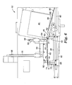
- FIG. 1 is an isometric view of a preferred embodiment of the apparatus for printing and applying tape of the present invention in a first position to apply printed tape to the top of an object;
- FIG. 2 is a front view of the apparatus for printing and applying tape of FIG. 1;
- FIG. 4 is a blown-up view of the underside of the vacuum system and tape puller of the taping head of FIG. 3;
- FIG. 5 is a side view of the taping head of FIG. 3, illustrating the tape puller starting to pull the tape from the printer;
- FIG. 6 is a side view of the taping head of FIG. 5, illustrating the tape puller pulling the printed tape from the printer as the printer prints the tape;
- FIG. 7 is a side view of the taping head of FIG. 6, illustrating the tape puller releasing the printed tape, the tape applicator holding the printed tape, and the tape cutter cutting the tape;
- FIG. 8 is a side view of the taping head of FIG. 7, illustrating the tape applicator holding the length of printed tape;
- FIG. 9 is a side view of the tape head of FIG. 8, illustrating the tape applicator initially applying the length of printed tape to a box;
- FIG. 10 a side view of the tape head of FIG. 9, illustrating the tape applicator finishing applying the length of printed tape to the box.
- the apparatus for printing and applying tape prints information onto tape to form a length of printed tape and then applies the length of printed tape to an object, preferably a package or a box.
- the apparatus may vary the information printed on each length of printed tape and may vary the overall length of each length of printed tape, such that different lengths of printed tape may be produced from one supply roll of tape.
- the apparatus applies the length of printed tape onto an object, preferably a package or box, either while the package or box is stationary or while the box is moving (such as while the box is being closed and sealed).
- the apparatus can apply the length of printed tape anywhere on the package or box to serve as a conveyor of information.
- the apparatus can apply the length of printed tape on the top, bottom, or sides of a package or box to convey information about the contents of the box.
- the apparatus can apply the length of printed tape along a seam of the box to convey information about the contents of the box and to seal the box.
- FIGS. 1 and 2 A preferred embodiment of an apparatus 10 for printing and applying tape of the present invention is illustrated in FIGS. 1 and 2.
- the tape applicator 10 includes a taping head 12 and a stand 14 .
- the stand 14 includes a first end 16 and a second end 18 opposite the first end 16 .
- the stand 14 includes preferably three legs 20 attached to the second end 18 of the stand 14 to support the stand 14 and the taping head 12 .
- Each of the legs 20 includes at least one foot 19 for supporting the leg.
- the taping head 12 is attached to the first end 16 of the stand 14 .
- the taping head 12 is slideably attached to a first rod 110 that is perpendicular to the stand 14 .
- the tape head 12 may be moved anywhere along the first rod 110 by turning the lead screw 118 .
- the first rod 110 is attached to the second rod 114 by slider assembly 112 .
- the slider assembly 112 includes a pivot to allow the first rod 110 and the taping head 12 to rotate relative to second rod 114 to allow the taping head to be moved into an alternative position to apply tape to sides of boxes.
- the second rod 114 is perpendicular to the first rod 110 .
- the slider assembly 112 moves up or down the second rod 114 to adjust the height of the taping head 12 relative to the floor.
- the taping head 12 may be mounted on the stand 14 in any orientation or position that allows it to apply printed tape to an object.
- FIGS. 3 and 4 illustrate a preferred embodiment of the taping head 12 of the apparatus 10 .
- FIGS. 3 and 4 are convenient for describing the parts of the taping head 12 and do not illustrate any tape in the taping head 12 .
- FIGS. 5 - 9 illustrate the taping head 12 in operation including tape.
- the taping head 12 includes a base 21 .
- the taping head 12 includes a tape supply holder 22 attached to the base 21 .
- the tape supply holder 22 preferably includes two opposing guides 24 for laterally supporting a roll of tape. Alternatively, the tape supply holder 22 could be configured to hold a stack of individual lengths of tape.
- the taping head 12 also includes a drive roller 26 and a support 28 attached to the base 21 for supporting the drive roller 26 .
- a motor (not shown) drives the drive roller 26 .
- the drive roller 26 assists in stripping or pulling tape from a tape roll that will be mounted in the tape supply holder 22 .
- Idler rollers 30 , 32 are attached to the base 21 .
- An accumulator 34 is attached to the base 21 .
- the accumulator is a dancer arm 34 with an idler roller 36 .
- the dancer arm 34 is attached to the base 21 by a pivot 38 opposite the idler roller 36 .
- the accumulator 34 could be any mechanism known in the art that allows the tape to accumulate along a tape path in the taping head 12 .
- the accumulator 34 could be a linear slide, a festoon or a loose loop of tape.
- the taping head 12 also includes a sensor 44 attached to the base 21 located adjacent the dancer arm 34 .
- An example of a suitable sensor 44 is commercially available as a proximity sensor from Turk Inc. located in Minneapolis, Minn. under part number Ni-4-S12-AN6X-H114.
- FIG. 3 illustrates the dancer arm 34 in a first position.
- the dancer arm 34 pivots counter clockwise from the first position to an alternative position or second position, the dancer arm 34 triggers the sensor 44 .
- the dancer arm 34 includes a spring (not shown) that biases the dancer arm 34 into the first position.
- sensor 44 When sensor 44 is triggered, a signal is sent to the motor on the drive roller 26 to start rotating the roller 26 to pull tape from the tape supply roll.
- the dancer arm 34 , the drive roller 26 , idler rollers 30 , 32 , and sensor 44 are configured to help feed tape from the tape supply holder 22 to the entrance of the printer 40 , while the printer prints on the tape.
- the taping head 12 could include a roller with a load cell sensor (instead of an accumulator 34 ), which senses when the tape is tensioned around the roller as it is being pulled toward the printer. When the sensor in the roller senses that the tape is being pulled around the roller to the printer, a signal is sent to the motor on the drive roller 26 to start rotating the roller 26 to pull tape from the tape supply roll.
- the taping head includes some type of mechanism that starts to pull tape from the tape supply roll when the printer 40 starts to print. This delivers the tape to the printer 40 in a uniform, low tension manner.
- other tape supply mechanisms known in the art may be used.
- the taping head 12 includes a printer 40 attached to the base 21 .
- the printer 40 preferably includes a drive roller 41 or platen roller 41 at the exit of the printer.
- the drive roller 41 serves as a support surface or a platen for the tape as it is being printed by a print head opposite the drive roller 41 .
- the drive roller 41 also pushes the printed tape out the exit of the printer as it rotates.
- Examples of a suitable printers 40 include a thermal transfer printer commercially available under model number M8485Se from Sato America Inc. located in Sunnyvale, Calif. or a thermal transfer printer under model number PE-42 from Datamax Inc. located in Orlando, Fla.
- the tape puller independently could pull the tape of the printer.
- that type of printer may not have a driven platen roller, it may include an idle platen roller at the exit of the printer.
- the taping head 12 includes a cutter 46 attached to the base 21 located adjacent the exit of the printer 40 .
- the cutter 46 cuts the printed tape after the printer 40 prints on the tape and the tape exits the printer.
- the cutter 46 preferably includes an upper blade 50 and a lower blade 48 .
- the upper blade 50 is slideably attached to the base 21 by an upper blade support 54 and the lower blade 48 is attached to the base 21 by lower blade support 52 .
- Preferably both blades 48 , 50 are coated with an anti-stick coating, such as fluoropolymer or machine oil, to help prevent the tape from sticking to the blades and to minimize the transfer of the adhesive from the tape to the blades when the blades cut the tape.
- the cutter 46 also includes an actuator 56 , which is preferably an air cylinder.
- the actuator 56 moves the upper blade support 54 and thus, the upper blade 50 in a vertical direction along guides 58 towards the lower blade 48 .
- the lower blade 48 and lower blade support 52 are stationary.
- the actuator could move both blades 48 , 50 to cut the tape.
- the actuator could move the lower blade 48 towards the upper blade 50 .
- the upper blade 50 and lower blade 48 are preferably offset from each other, so that when the actuator 56 actuates the upper blade support 54 , the upper blade slides next the lower blade 48 , similar to a pair of blades of scissors.
- the tape cutter could be any cutter known in the art, for example, a single blade, a hot wire cutter, or a laser.
- the taping head 12 includes a tape applicator 60 attached to the base 21 adjacent the cutter 46 .
- the tape applicator temporarily holds the printed tape after it exits the printer 40 and then applies the printed tape to an object, preferably a package or a box.
- the tape applicator 60 is movable along an applicator path between a first position (illustrated in FIG. 3) and a second position (illustrated in FIG. 9) adjacent the object for applying the printed tape to the object.
- the tape applicator 60 moves between these two positions by use of an actuator 68 and guides 70 .
- the actuator 68 is an air cylinder.
- the tape applicator 60 includes a vacuum system.
- the vacuum system includes a vacuum source 64 attached to a vacuum box 62 to hold the printed tape.
- the vacuum source 64 includes two different types of vacuum sources.
- the first vacuum source is a low vacuum, high-flow source.
- a suitable example of this type of vacuum source 64 is commercially available as a fan from Grainger Industrial Supply located in St. Paul, Minn. under the brand Dayton, model number 4C548.
- the second vacuum source is a high vacuum, low-flow source.
- a suitable example of this type of vacuum source is commercially available as a vacuum pump, under the brand PIAB, model number M-20 from PIAB USA located in Hingham, Mass.
- the vacuum system 60 preferably includes a wipe down plate 65 , which assists in initially adhering the length of printed tape to the object and assists in wiping down the printed tape as it is applied.
- the wipe down plate 65 preferably includes an actuator 61 for moving the wipe down plate 65 to apply the tape.
- the apparatus 10 could include an optional buffing assembly, which buffs the printed tape after it has been applied to the object.
- the taping head 12 includes a tape puller 72 slideably attached the base 21 located beneath the tape applicator 60 .
- the tape puller pulls the printed tape as the tape exits the printer 40 .
- the tape puller 72 includes an actuator 80 (shown in FIGS. 5 - 9 ), which moves the tape puller from a first position adjacent the exit of the printer 40 to a second position that is distant from the exit of the printer 40 .
- the actuator 80 is an air cylinder.
- FIG. 4 is convenient for describing the tape applicator 60 and the tape puller 72 in more detail.
- the tape applicator 60 includes a low vacuum, high-flow source and high vacuum, low-flow source (shown collectively as the vacuum source 64 ), a vacuum box 62 attached to the vacuum source 64 , and a wipe down plate 65 attached to the vacuum box 62 .
- the low vacuum, high-flow source provides a vacuum through the vacuum box 62 and through holes 66 arranged throughout the wipe down plate 65 .
- the wipe down plate 65 includes at least two holes 67 located closest to the cutter 46 .
- the high vacuum, low-flow source provides a vacuum through the vacuum box 62 and through holes 67 .
- the tape applicator 60 includes both types of vacuum sources for holding the tape to the tape applicator 60 . If only the high vacuum, low-flow source was included, then all the holes in the vacuum box would need to be covered by the tape. If all the holes were not covered, then the vacuum would be lost and the tape applicator would not be able to adequately hold the tape. If only the low vacuum, high-flow source was included, then the tape would not be held securely or sufficiently by the tape applicator. By using both vacuum sources, the low vacuum, high-flow source gently holds the tape to the applicator through holes 66 all over the vacuum box 62 and the high vacuum, low-flow source securely holds the tape to the applicator through holes 67 .
- the tape it is preferable to hold the tape strongly to the tape applicator 60 closest to the tape cutter 46 because the tape might otherwise change position on the box 62 after the cutter 46 cuts the tape.
- the tape normally covers the two holes 67 and as a result, the vacuum is not lost.
- the tape puller 72 preferably includes a tape gripper 74 and an actuator 80 for moving the tape gripper 74 along rods 82 .
- the tape gripper 74 preferably includes an upper jaw 76 , which in the illustrated embodiment remains stationary, and a lower jaw 78 , which is moved vertically by an actuator 84 .
- the actuator 84 is an air cylinder.
- the lower jaw 78 is moved toward the upper jaw by the actuator 84 to close the jaws on the tape and to grab the end of the tape as it leaves the printer 40 from drive roller 41 .
- the upper jaw 76 may move and the lower jaw may be stationary or both jaws 76 , 78 may move to close the jaws on the tape and to grab the end of the tape.
- the lower jaw 78 includes an anti-stick coating along its surface, such as a coating of fluoropolymer or silicone to help prevent the adhesive from the tape from sticking to the lower jaw 78 .
- the tape puller 72 is preferably configured to grab just enough of the end of the tape to adequately pull the tape from the printer, but not to grab too much of the tape so that the bottom jaw 78 sticks to the adhesive on the tape.
- the jaws 76 , 78 grab between 0.25 and 0.50 inches (0.635 cm to 1.27 cm) of the length of the tape, as it exits the printer 40 .
- the lower jaw 78 could include teeth, grooves, or other surface modifications. However, any portion of the tape extending from the printer could be grasped by the tape puller, so long as the tape puller can adequately disengage from the tape.
- the “upper” and “lower” jaw does not imply any orientation relative to up or down.
- the grippers maybe oriented sideways, or with the lower jaw above the upper jaw, depending on the application.
- the tape gripper 74 is attached to a slider 85 , which is slideably engaged with the rods 82 .
- the actuator 80 moves the slider 86 and thus, the tape gripper 74 , between a first position located adjacent the tape cutter 46 and printer 40 and a second position towards the opposite ends of the rods 82 away from the tape cutter 46 and printer 40 .
- the tape puller 72 moves from the first position to the second position opposite the first position, it pulls the tape from the printer 40 under or in the path of the tape applicator 60 .
- the tape puller 72 when the tape puller 72 is in the second position, it is clear from the line of the motion of the tape applicator, so when the tape applicator moves from a first position to a second position to apply the tape to the object, the tape applicator 60 can move without interference from the tape puller 72 .
- FIG. 5 is convenient for describing the preferred tape path through the taping head 12 .
- a tape roll 92 is mounted on the tape supply holder 22 supported by the tape guides 24 .
- the tape 90 includes a backing 86 and an adhesive 88 on the backing 86 .
- An example of a suitable tape is commercially available as Scotch brand tape, No. 3340 from 3M Company, located in St. Paul, Minn.
- the tape 90 preferably moves along the following tape path within the taping head 12 : a) from the tape supply holder 22 to the drive roller 26 ; b) then to the idler roller 30 ; c) then to the idler roller 36 on dancer arm 34 ; d) then to the idler roller 32 ; e) then to the entrance of the printer 40 ; f) then through the printer to the drive roller 41 at the exit of the printer 40 ; g) then between the upper blade 50 and the lower blade 48 of the tape cutter 46 ; and h) then to the upper jaw 76 and lower jaw 78 of the tape puller, which will pull the tape across the path of the tape applicator 60 .
- the tape is initially threaded through the taping head 12 according to the tape path outlined above.
- FIGS. 5 - 9 The preferred sequence of operations of the apparatus 10 for printing and applying tape is illustrated in FIGS. 5 - 9 and is as follows.
- FIG. 5 illustrates the taping head 12 before the printer 40 starts printing on the tape 90 .
- the first actuator 80 previously moved the tape puller 72 along the rods 82 (to the right in the Figure) to a first position adjacent the exit of the printer 40 and between the blades 48 , 50 of the tape cutter 46 .
- the fifth actuator 84 previously moved the lower jaw 78 of the tape puller 72 to grasp the first end 96 of the tape 90 between the upper jaw 76 and the lower jaw 78 .
- the first actuator 80 applies a force to move the tape puller away from the printer (to the left in the Figure). However, the force is not great enough to pull the tape 90 from the printer 40 when the printer 40 is not printing.
- the gripper moves as the printer feeds the tape out the exit of the printer. In this position, the tape 90 is being held under tension.
- the tape puller 72 moves from the first position towards the second position, it will pull the tape 90 past the path of the tape applicator 60 .
- the path of the tape applicator is the movement of the tape applicator 60 from its first position to its second position, as explained in more detail below.
- a signal is sent to operate the fifth actuator 84 to move the lower jaw 78 of the tape puller away from the upper jaw 76 .
- the printed tape is released from the tape puller 72 and no longer under tension.
- the tape puller may need to move out of the path of the tape applicator that moves later to apply the printed tape.
- the actuator 80 may continue to push the tape puller away from the printer out of the path of the tape applicator, towards the second position located near the end of the bars 82 .
- the vacuum system of the tape applicator 60 was previously turned on (prior to the printing step)
- the vacuum system draws the printed tape 90 toward the vacuum box 62 .
- This step is illustrated in FIG. 7, with the tape applicator 60 holding the printed tape.
- the printed side of the tape 90 is in contact with the wipe down plate 65 .
- the high vacuum, low-flow vacuum through holes 67 strongly holds the portion of the tape closest to the tape cutter 46 and printer 40 , while the low vacuum, high flow vacuum through holes 66 loosely holds the other portion of the tape.
- FIG. 8 illustrates the cutter 46 cutting the tape.
- the end of the tape 90 is nearly always is the same location after backing up the tape so this provides a predictable location for the tape puller 72 to grasp the end of the tape on the next cycle. Lastly, by backing up the tape, it helps maximize the print area of the tape by starting to print at a location closer to the first end of the tape.
- FIG. 9 illustrates the tape applicator 60 moved along the applicator path from the first position to a second position to apply the cut length of tape 94 being initially applied to an object 100 , which is preferably a package or a box.
- the second actuator 68 moves the tape applicator 60 with the length of tape held by the vacuum system.
- the fourth actuator 61 pivots the wipe on plate 65 so as to adhere the second end 98 of the tape to the box 100 .
- the adhesive 88 of the second end 98 of the cut length of tape sticks the tape to the box 100 .
- FIG. 10 illustrates the applicator 60 finishing applying the length of tape 94 to the box.
- the wipe on plate 65 wipes down the entire length of tape 94 along the box, including the first end 96 of the tape 94 .
- the adhesive 88 of the cut length of tape sticks the tape to the box 100 .
- the tape puller 72 could include a roller instead of two jaws 76 , 78 for grabbing the adhesive side of the tape.
- the roller would remain stationary when the tape puller attaches the roller to the adhesive side of the tape and when the tape puller moves to the second position. What is important is that the puller maintains the tape under tension as it is pulled across the tape applicator path. Once in the second position, the tape puller would continue to move to the left and the roller would rotate to release the tape from the roller.
- the tape puller 72 could include any combination of rollers or jaws for pulling the tape from the printer.
- the tape applicator could temporarily hold the tape by static charge, by pressure-sensitive adhesive or other means known in the art instead of a vacuum system tape applicator temporarily holding the length of tape 94 .
- the tape applicator 60 could move to an intermediate position between the first position and the second position to temporarily adhere the printed tape to the tape applicator and then proceed to the second position to adhere the printed tape to the box.
- the tape applicator 60 does not need to include a wipe on pate 65 . Instead, the tape applicator 60 could attach the printed tape 94 to the box by tamping the printed tape on the package or box.
- the box may be stationary while the tape applicator 60 tamps the printed tape on the package or box or the tape applicator 60 could e move in the same direction as the box moves, when the tape applicator tamps the printed tape on the box.
- the tape applicator could be stationary and tamp the printed tape on the box as the box moves past the applicator.
- the tape applicator could include an air source for blowing the printed tape off the applicator onto the box to apply the printed tape to the box.
- the tape cutter 46 and the tape applicator 60 could be one mechanism. In this embodiment, a single blade would be attached to the tape applicator 60 .
- the blade would cut through the tape and the vacuum system of the tape applicator would draw the cut tape to the vacuum box.
- the tape applicator and blade would then move the second position to apply the printed tape to the box.
- the blade could be configured to not contact the box when the applicator applies the printed tape to the box.
- the tape cutter could be a single blade or hot wire cutter mounted to the tape head located below the exit of the printer. In this embodiment, as the tape applicator moves from the first position to the second position, the tape applicator would bring the printed tape 94 past the stationary blade or hot wire, thus cutting through the tape.
- Examples of suitable actuators for the first actuator 80 for moving the tape puller 72 , the second actuator 68 for moving the tape applicator 60 , the third actuator 56 for moving the tape cutter, the fourth actuator 61 for moving the wipe on plate 65 , and the fifth actuator 84 for moving the lower jaw 78 of the tape puller 72 are commercially available as air cylinders, model number CM2C25-100A from SMC Corporation of America located in Eden Prairie, Minn. and air cylinders, model number, DSNU-16250-PPV-A, available from Festo Corporation located in Hauppauge, N.Y. Although the apparatus 10 is illustrated as including five actuators, the apparatus may include any number of actuators.
- the apparatus 10 for printing and applying tape includes a programmable logic controller for operating the various actuators, sensors, motors, and the printer in particular sequence.
- a programmable logic controller for operating the various actuators, sensors, motors, and the printer in particular sequence.
- a suitable example of a commercially available controller is available as a controller under the brand name Micrologix, model number 1000 1761-L32BB from Allen Bradley located in Milwaukee, Wis.
Abstract
An apparatus for printing and applying tape. A preferred embodiment of the invention provides an apparatus that includes a printer for printing on tape, a tape puller that pulls the printed tape out from the printer, and an applicator that applies the printed tape to an object. The present invention also generally relates to methods of printing and applying tape to objects.
Description
- The present invention generally relates to an apparatus for printing and applying tape. The present invention relates more particularly to an apparatus that includes a printer for printing on tape, a tape puller that pulls the printed tape out from the printer, and an applicator that applies the printed tape to an object. The present invention also generally relates to methods of printing and applying tape to objects.
- Containers, packages, and boxes for storing and shipping products typically use box sealing tape, such as an adhesive tape, to secure the flaps or covers so that the container, package, or box will not accidentally open during normal shipment, handling, and storage. Box sealing tape maintains the integrity of a container, package, or box throughout its entire distribution cycle. Box sealing tape can be used on other parts of container, package, or box and on other substrates, and can be used to function in a manner similar to labels. These tapes can be made in roll or pad form, and can have information printed or otherwise applied to, or contained within or on, the tape.
- These containers, packages, or boxes generally display information about their contents. This information most commonly located on the container, package, or box might include lot numbers, date codes, product identification information, and bar codes. The information can be placed onto the container, package, or box using a number of methods. These include preprinting the container, package, or box when it is manufactured, printing this information onto the container, package, or box at the point of use with an inkjet code that sprays a pattern of ink dots to form the image, or by using a flexographic ink rolling coding system. Other approaches include the use of labels, typically white paper with preprinted information either applied manually, or with an online automatic label applicator.
- A recent trend in conveying information related to the product is the requirement to have the information specific for each container, package, or box. For example, each container, package, or box can carry specific information about its contents and the final destination of the product, including lot numbers, serial numbers, and customer order numbers. The information is typically provided on labels that are customized and printed on demand at the point of application onto the container, package, or box. This is typically known as the ability to print “variable” information onto a label before it is applied onto the container, package, or box. Two patents that disclose printed labels are U.S. Pat. Nos. 5,292,713 and 5,661,099. U.S. Pat. No. 2,492,908 discloses a label applying mechanism.
- One system for printing variable information involves thermal transfer ink printing onto labels using an ink ribbon and a special heat transfer print head. A computer controls the print head by providing input to the head, which heats discrete locations on the ink ribbon. The ink ribbon directly contacts the label so that when a discrete area is heated, the ink melts and is transferred to the label. Another approach using this system is to use labels that change color when heat is applied (direct thermal labels). In another system, variable information is directly printed onto a box or label by an inkjet printer including a print head. A computer can control the ink pattern sprayed onto the box or label.
- Both thermal transfer and inkjet systems produce sharp images. Inkjet systems include piezo, thermal, continuous, and drop-on-demand. With both inkjet and thermal transfer systems, the print quality depends on the surface on which the ink is applied. It appears that the best system for printing variable information is one in which the ink and the print substrate can be properly matched to produce a repeatable quality image, especially bar codes, that must be read by an electronic scanner with a high degree of reliability.
- Regardless of the specific printing technique, the printing apparatus includes a handling system for guiding a continuous web of label tape to the print head, as well as away from the print head following printing for subsequent placement on the article of interest (for example, a box). To this end, the web of label tape is normally provided in a rolled form (“tape supply roll”), such that the printing device includes a support that rotatably maintains the tape supply roll. Further, a series of guide components, such as rollers, transfer plates, festoons, etc., are utilized to establish a desired tape path both upstream and downstream of the print head, with the terms “upstream” and “downstream” in reference to a tape transport path initiating at the tape supply roll and terminating at the point label application to the article of interest (e.g., a box). An exact configuration of the guide components is directly related to the form of the label tape.
- In particular, label tape is provided as either a linered tape or as a linerless tape. As suggested by its name, linered tape includes both a tape defined by a print side and an adhesive side, and a release liner encompassing the adhesive side. The liner serves as the carrier for the label tape. With this configuration, the printing device normally includes components that, in addition to delivering the web to and from the print head, also peel the liner away from the label tape. While widely accepted, linered tape material is relatively expensive due to the cost associated with inclusion of the release liner. Further, the liner adds to the overall thickness, thereby decreasing the available length of label tape for a given tape supply roll diameter. A decreased label tape length requires more frequent changeovers of the tape supply roll (where the exhausted tape supply roll is replaced by a new roll), and therefore a loss in productivity. Additionally, because the liner material is typically paper, resultant fibers, debris, and dust can contaminate the printing mechanism, potentially resulting in a reduced print head life. Also, a die cut operation is typically performed on the label stock to generate labels of discrete size. The die cut operation is an additional manufacturing step (and therefore expense), and prevents implementation of a variable label length processing approach.
- To overcome the above-described problems associated with linered label tape, a linerless format has been developed. Generally speaking, linerless label tapes are similar to the linered configuration, except that the liner is no longer included. Thus, the linerless label tape is defined by a non-adhesive side or backing formulated to receive printing (“print side”) and an opposing side (or “non-print side”) that often times carries an adhesive (“adhesive side”). By eliminating the liner, linerless label tapes have a greatly increased length for a given roll diameter, and eliminate many of the other above-listed processing concerns associated with linered label tape. However, certain other handling issues are presented.
- In particular, as the web of linerless tape is pulled or extended from the supply roll, the adhesive side is exposed, and will readily adhere to surfaces, and in particular the guide components associated with the printing device. A common difficulty encountered in the handling of linerless label tape is “wrap-around”, whereby the web adheres to and wraps around a roller otherwise in contact with the adhesive side. For example, with thermal transfer printing, a platen roller or drive roller is normally associated with the print head for supporting the label tape during printing by the print head and for driving the tape out the printer exit. In this regard, the adhesive side of the linerless tape is in contact with, and carried by, the drive roller. Invariably, instead of simply releasing from the drive roller, the adhesive side adheres to and wraps around the drive roller. This highly undesirable situation leads to printer malfunctions, such as misprinting, tape jams, etc. Wrap-around of the platen roller or drive roller is most commonly found in printing devices conforming with “next label out” protocol where, after the label is printed, it is immediately cut and applied to the article in question. In other words, there is no accumulation of printed labels between the print head and the application device, in contrast to typical “loose loop” systems where printed labels accumulate prior to cutting and thus includes guide components, such as festoons, to tension the linerless label tape off of the drive roller.
- Many efforts have been made to address the “wrap-around” concern associated with linerless label tape in next label segment out printing systems, including those described in U.S. Pat. Nos. 5,674,345; 5,524,996; 5,487,337; 5,497,701; and 5,560,293. In summary, each of these references incorporates a device, such as a stripper bar, a stripper plate, or an air source, that interacts with the linerless label tape after it has undesirably adhered to the platen or drive roller. That is to say, the common technique for addressing drive roller wrap-around is to position a device adjacent the platen roller that effectively “scrapes” the linerless label tape off of the platen or drive roller in the event of platen or drive roller wrap-around.
- Other efforts have been made to address the “wrap-around” concern associated with linerless label tape in printing systems, such as those described in U.S. Pat. Nos. 5,437,228; 5,940,107; 5, 879,507; and EP 0637547 B1 and EP 0834404.
- Various apparatuses and methods for printing on tape and applying a length of printed tape to articles are known in the art. For example, apparatuses for printing and applying tape are described in U.S. Pat. No. 6,049,347 (Ewert et al.), “Apparatus for Variable Image Printing on Tape,” U.S. Pat. No. 6,067,103 (Ewert et al.) “Apparatus and Process for Variable Image Printing on Tape,” PCT Publication WO 98/42578 (Lenkl) “Device and Method for Applying Linerless Labels,” and PCT Publication WO 00/34131 (Faust et al.) “Variably Printed Tape And System For Printing And Applying Tape Onto Surfaces.” 3M Company located in St. Paul, Minn. has sold print and apply case sealing applicators and print and apply corner sealing applicators under the brand name 3M-Matic as CA2000 Corner Label Applicator and PS2000 Print & Seal Applicator.
- Print and apply label applicators are commercially available from Etipack, S.p.A. located in Cinesello Balsamo (MI), Italy under the brand names Drinjet, Drinfit, Drinedge and AP Euro. Tape dispensers are also commercially available from Etipack, S.p.A. located in Cinesello Balsamo (MI), Italy under the brand name Strappy. Although the commercial success of available print and apply tape or label applicators have been impressive, it is desirable to further improve the performance of applicators handling linerless label tapes which print on the tape and apply the tape to objects, such as packages or boxes, while minimizing or eliminating the concern of platen or drive roller wraparound.
- One aspect of the present invention provides an apparatus for printing and applying tape. This apparatus comprises: a tape supply holder; a printer for printing on tape; a tape puller for pulling printed tape from the printer; and a tape applicator for applying the printed tape to an object. In one preferred embodiment of the above apparatus, the tape puller keeps the printed tape under tension as the printed tape exits the printer.
- In another preferred embodiment of the above apparatus, the tape puller is moveable between a first position adjacent the printer and a second position distant from the printer. In one aspect of this embodiment, when the tape puller moves from the first position to the second position, the tape puller pulls the printed tape in the path of the tape applicator. In another aspect of this embodiment, after the printer has finished printing, the tape puller releases the printed tape. In another aspect of this embodiment, the tape applicator includes a vacuum system, where after the tape puller releases the printed tape, the vacuum system holds the printed tape. In another aspect of this embodiment, the apparatus further comprises a tape cutter, where after the vacuum system holds the printed tape, the tape cutter cuts the printed tape to form a length of printed tape. In yet another aspect of this embodiment, the tape applicator is moveable between a first position and a second position to apply the printed tape to the object, and after the tape cutter cuts the printed tape, the tape applicator moves to the second position to apply the printed tape to an object. In another aspect of this embodiment, the printer includes a driven roller, when as the printer is printing the tape, the driven roller drives the tape along a tape path in a first direction, and when after the cutter cuts the printed tape, the driven roller drives the tape along the tape path in a second direction opposite the first direction.
- In another preferred embodiment of the above apparatus, the apparatus includes a first actuator for moving the tape puller between the first position and the second position. In another preferred embodiment of the above apparatus, the tape applicator is moveable between a first position and a second position to apply the printed tape to the object. In another aspect of this embodiment, the apparatus includes a second actuator for moving the tape applicator between the first position and the second position. In another preferred embodiment of the above apparatus, the applicator further comprises a tape cutter. In yet another aspect of this embodiment, the tape applicator includes a vacuum system for holding the printed tape prior to application on an object. In another aspect of this embodiment, the apparatus further comprises a drive roller for pulling tape from the tape supply holder.
- Another aspect of the present invention provides an alternative apparatus for printing and applying tape. This apparatus comprises: a tape supply holder; a printer; a gripper; a first actuator for moving the gripper between a first position adjacent the printer and a second position distant from the printer; and a tape applicator. In another preferred embodiment of the above apparatus, the gripper and actuator keep printed tape under tension as the printed tape exits the printer.
- In another preferred embodiment of the above apparatus, when the gripper moves from the first position to the second position, the gripper pulls printed tape in the path of the tape applicator. In another aspect of this embodiment, after the printer has finished printing, the gripper releases the printed tape. In another aspect of this embodiment, the apparatus further comprises a vacuum system, where after the gripper releases the printed tape, the vacuum system holds the printed tape. In another aspect of this embodiment, the apparatus further comprises a tape cutter, where after the vacuum system holds the printed tape, the tape cutter cuts the printed tape to form a length of printed tape. In another aspect of this embodiment, the tape applicator is moveable between a first position and a second position to apply the printed tape to the object, and where after the tape cutter cuts the printed tape, the tape applicator moves to the second position to apply the printed tape to an object. In another aspect of this embodiment, the printer includes a driven roller, where as the printer is printing the tape, the driven roller drives the tape along a tape path in a first direction, where after the cutter cuts the printed tape, the driven roller drives the tape along the tape path in a second direction opposite the first direction.
- In another preferred embodiment of the above apparatus, the tape applicator is moveable between a first position adjacent the printer and a second position to apply the printed tape to the object. In another aspect of this embodiment, the apparatus includes a second actuator for moving the tape applicator between the first position and the second position. In another preferred embodiment of the above apparatus, the apparatus further comprises a tape cutter. In another aspect of this embodiment, the tape applicator includes a vacuum system for holding the printed tape prior to application on an object. In another preferred embodiment of the above apparatus, the apparatus further comprises a driven roller for pulling tape from the tape supply holder.
- Another aspect of the present invention provides a method of printing and applying tape, comprising the steps of: providing tape; printing on the tape with a printer; pulling printed tape under tension from the printer; and applying printed tape to an object. In one preferred embodiment of the above method, the pulling step occurs simultaneously during the printing step. In another preferred embodiment of the above method, the method comprising the further step of: prior to the applying step, holding the printed tape. In another aspect of this embodiment, the method comprising the further step of: after the holding step, cutting the printed tape to provide a length of printed tape. In another aspect of this embodiment, the pulling step includes pulling the printed tape across the path of a tape applicator for applying the printed tape to an object. In another aspect of this embodiment, after the printing step and pulling step are complete, releasing the printed tape. In another aspect of this embodiment, during the printing step, the tape moves along a tape path in the printer in a first direction, where after cutting step, the tape moves along the tape path in a second direction opposite the first direction. In another preferred embodiment of the above method, the applying step includes pushing on a non-adhesive side of the printed tape to apply an adhesive side of the printed tape to an object. In another aspect of this embodiment, the pushing step includes pushing the printed tape from a first position to a second position to apply the printed tape to the object across the direction of the pull step. In another preferred embodiment of the above method, the method further comprises the step of: providing an object where the printing step includes printing information on the tape corresponding to the object. In another aspect of this embodiment, the object is a package with contents, where the printing step includes printing information on the tape corresponding to the contents.
- The present invention will be further explained with reference to the appended Figures, wherein like structure is referred to by like numerals throughout the several views, and wherein:
- FIG. 1 is an isometric view of a preferred embodiment of the apparatus for printing and applying tape of the present invention in a first position to apply printed tape to the top of an object;
- FIG. 2 is a front view of the apparatus for printing and applying tape of FIG. 1;
- FIG. 3 is an isometric view of the taping head of the apparatus for printing and applying tape of FIG. 1;
- FIG. 4 is a blown-up view of the underside of the vacuum system and tape puller of the taping head of FIG. 3;
- FIG. 5 is a side view of the taping head of FIG. 3, illustrating the tape puller starting to pull the tape from the printer;
- FIG. 6 is a side view of the taping head of FIG. 5, illustrating the tape puller pulling the printed tape from the printer as the printer prints the tape;
- FIG. 7 is a side view of the taping head of FIG. 6, illustrating the tape puller releasing the printed tape, the tape applicator holding the printed tape, and the tape cutter cutting the tape;
- FIG. 8 is a side view of the taping head of FIG. 7, illustrating the tape applicator holding the length of printed tape;
- FIG. 9 is a side view of the tape head of FIG. 8, illustrating the tape applicator initially applying the length of printed tape to a box; and
- FIG. 10 a side view of the tape head of FIG. 9, illustrating the tape applicator finishing applying the length of printed tape to the box.
- The apparatus for printing and applying tape prints information onto tape to form a length of printed tape and then applies the length of printed tape to an object, preferably a package or a box. The apparatus may vary the information printed on each length of printed tape and may vary the overall length of each length of printed tape, such that different lengths of printed tape may be produced from one supply roll of tape. The apparatus applies the length of printed tape onto an object, preferably a package or box, either while the package or box is stationary or while the box is moving (such as while the box is being closed and sealed). The apparatus can apply the length of printed tape anywhere on the package or box to serve as a conveyor of information. For example, the apparatus can apply the length of printed tape on the top, bottom, or sides of a package or box to convey information about the contents of the box. Alternatively, the apparatus can apply the length of printed tape along a seam of the box to convey information about the contents of the box and to seal the box.
- A preferred embodiment of an
apparatus 10 for printing and applying tape of the present invention is illustrated in FIGS. 1 and 2. Thetape applicator 10 includes a tapinghead 12 and astand 14. Thestand 14 includes afirst end 16 and asecond end 18 opposite thefirst end 16. Thestand 14 includes preferably threelegs 20 attached to thesecond end 18 of thestand 14 to support thestand 14 and the tapinghead 12. Each of thelegs 20 includes at least onefoot 19 for supporting the leg. - As illustrated in the FIG. 2, the taping
head 12 is attached to thefirst end 16 of thestand 14. Preferably, the tapinghead 12 is slideably attached to afirst rod 110 that is perpendicular to thestand 14. Thetape head 12 may be moved anywhere along thefirst rod 110 by turning thelead screw 118. Thefirst rod 110 is attached to thesecond rod 114 byslider assembly 112. Theslider assembly 112 includes a pivot to allow thefirst rod 110 and the tapinghead 12 to rotate relative tosecond rod 114 to allow the taping head to be moved into an alternative position to apply tape to sides of boxes. Thesecond rod 114 is perpendicular to thefirst rod 110. By turning thelead screw 116, theslider assembly 112 moves up or down thesecond rod 114 to adjust the height of the tapinghead 12 relative to the floor. The tapinghead 12 may be mounted on thestand 14 in any orientation or position that allows it to apply printed tape to an object. - FIGS. 3 and 4 illustrate a preferred embodiment of the taping
head 12 of theapparatus 10. FIGS. 3 and 4 are convenient for describing the parts of the tapinghead 12 and do not illustrate any tape in the tapinghead 12. FIGS. 5-9 illustrate the tapinghead 12 in operation including tape. - The taping
head 12 includes abase 21. The tapinghead 12 includes atape supply holder 22 attached to thebase 21. When the term “attached” is use herein, it shall broadly-mean any way known in the art of attaching two items together either directly or indirectly to each other. Thetape supply holder 22 preferably includes two opposingguides 24 for laterally supporting a roll of tape. Alternatively, thetape supply holder 22 could be configured to hold a stack of individual lengths of tape. The tapinghead 12 also includes adrive roller 26 and asupport 28 attached to thebase 21 for supporting thedrive roller 26. A motor (not shown) drives thedrive roller 26. Thedrive roller 26 assists in stripping or pulling tape from a tape roll that will be mounted in thetape supply holder 22.Idler rollers base 21. - An
accumulator 34 is attached to thebase 21. In one preferred embodiment, the accumulator is adancer arm 34 with anidler roller 36. Thedancer arm 34 is attached to thebase 21 by apivot 38 opposite theidler roller 36. Alternatively, theaccumulator 34 could be any mechanism known in the art that allows the tape to accumulate along a tape path in the tapinghead 12. For example, theaccumulator 34 could be a linear slide, a festoon or a loose loop of tape. The tapinghead 12 also includes asensor 44 attached to the base 21 located adjacent thedancer arm 34. An example of asuitable sensor 44 is commercially available as a proximity sensor from Turk Inc. located in Minneapolis, Minn. under part number Ni-4-S12-AN6X-H114. - FIG. 3 illustrates the
dancer arm 34 in a first position. When thedancer arm 34 pivots counter clockwise from the first position to an alternative position or second position, thedancer arm 34 triggers thesensor 44. Thedancer arm 34 includes a spring (not shown) that biases thedancer arm 34 into the first position. Whensensor 44 is triggered, a signal is sent to the motor on thedrive roller 26 to start rotating theroller 26 to pull tape from the tape supply roll. (FIG. 5 illustrates the first position of theaccumulator 34 in solid lines and the second position of theaccumulator 34 in dotted lines.) Thedancer arm 34, thedrive roller 26,idler rollers sensor 44 are configured to help feed tape from thetape supply holder 22 to the entrance of theprinter 40, while the printer prints on the tape. In another preferred embodiment, the tapinghead 12 could include a roller with a load cell sensor (instead of an accumulator 34), which senses when the tape is tensioned around the roller as it is being pulled toward the printer. When the sensor in the roller senses that the tape is being pulled around the roller to the printer, a signal is sent to the motor on thedrive roller 26 to start rotating theroller 26 to pull tape from the tape supply roll. In either of the preferred embodiments, the taping head includes some type of mechanism that starts to pull tape from the tape supply roll when theprinter 40 starts to print. This delivers the tape to theprinter 40 in a uniform, low tension manner. Alternatively, other tape supply mechanisms known in the art may be used. - The taping
head 12 includes aprinter 40 attached to thebase 21. Theprinter 40 preferably includes adrive roller 41 orplaten roller 41 at the exit of the printer. Preferably, thedrive roller 41 serves as a support surface or a platen for the tape as it is being printed by a print head opposite thedrive roller 41. Thedrive roller 41 also pushes the printed tape out the exit of the printer as it rotates. Examples of asuitable printers 40 include a thermal transfer printer commercially available under model number M8485Se from Sato America Inc. located in Sunnyvale, Calif. or a thermal transfer printer under model number PE-42 from Datamax Inc. located in Orlando, Fla. or a thermal transfer printer under model DPM from NOVEXX OEM Printers and Labellers located in Philadelphia, Pa. In the case where a printer does not have atape drive roller 41 for pushing the printed tape out the exit of the printer, the tape puller (explained below) independently could pull the tape of the printer. In this case, even though that type of printer may not have a driven platen roller, it may include an idle platen roller at the exit of the printer. - The taping
head 12 includes acutter 46 attached to the base 21 located adjacent the exit of theprinter 40. Thecutter 46 cuts the printed tape after theprinter 40 prints on the tape and the tape exits the printer. In one embodiment, thecutter 46 preferably includes anupper blade 50 and alower blade 48. Theupper blade 50 is slideably attached to thebase 21 by anupper blade support 54 and thelower blade 48 is attached to thebase 21 bylower blade support 52. Preferably bothblades cutter 46 also includes anactuator 56, which is preferably an air cylinder. Theactuator 56 moves theupper blade support 54 and thus, theupper blade 50 in a vertical direction along guides 58 towards thelower blade 48. Thelower blade 48 andlower blade support 52 are stationary. Alternatively, the actuator could move bothblades lower blade 48 towards theupper blade 50. Theupper blade 50 andlower blade 48 are preferably offset from each other, so that when theactuator 56 actuates theupper blade support 54, the upper blade slides next thelower blade 48, similar to a pair of blades of scissors. Alternatively, the tape cutter could be any cutter known in the art, for example, a single blade, a hot wire cutter, or a laser. - The taping
head 12 includes atape applicator 60 attached to the base 21 adjacent thecutter 46. The tape applicator temporarily holds the printed tape after it exits theprinter 40 and then applies the printed tape to an object, preferably a package or a box. Thetape applicator 60 is movable along an applicator path between a first position (illustrated in FIG. 3) and a second position (illustrated in FIG. 9) adjacent the object for applying the printed tape to the object. Thetape applicator 60 moves between these two positions by use of anactuator 68 and guides 70. Preferably, theactuator 68 is an air cylinder. Preferably, thetape applicator 60 includes a vacuum system. The vacuum system includes avacuum source 64 attached to avacuum box 62 to hold the printed tape. Preferably, thevacuum source 64 includes two different types of vacuum sources. The first vacuum source is a low vacuum, high-flow source. A suitable example of this type ofvacuum source 64 is commercially available as a fan from Grainger Industrial Supply located in St. Paul, Minn. under the brand Dayton, model number 4C548. The second vacuum source is a high vacuum, low-flow source. A suitable example of this type of vacuum source is commercially available as a vacuum pump, under the brand PIAB, model number M-20 from PIAB USA located in Hingham, Mass. Thevacuum system 60 preferably includes a wipe downplate 65, which assists in initially adhering the length of printed tape to the object and assists in wiping down the printed tape as it is applied. The wipe downplate 65 preferably includes anactuator 61 for moving the wipe downplate 65 to apply the tape. Theapparatus 10 could include an optional buffing assembly, which buffs the printed tape after it has been applied to the object. - The taping
head 12 includes atape puller 72 slideably attached thebase 21 located beneath thetape applicator 60. The tape puller pulls the printed tape as the tape exits theprinter 40. Thetape puller 72 includes an actuator 80 (shown in FIGS. 5-9), which moves the tape puller from a first position adjacent the exit of theprinter 40 to a second position that is distant from the exit of theprinter 40. Preferably, theactuator 80 is an air cylinder. - FIG. 4 is convenient for describing the
tape applicator 60 and thetape puller 72 in more detail. As mentioned above, thetape applicator 60 includes a low vacuum, high-flow source and high vacuum, low-flow source (shown collectively as the vacuum source 64), avacuum box 62 attached to thevacuum source 64, and a wipe downplate 65 attached to thevacuum box 62. The low vacuum, high-flow source provides a vacuum through thevacuum box 62 and throughholes 66 arranged throughout the wipe downplate 65. Preferably the wipe downplate 65 includes at least twoholes 67 located closest to thecutter 46. The high vacuum, low-flow source provides a vacuum through thevacuum box 62 and throughholes 67. It is preferred that thetape applicator 60 includes both types of vacuum sources for holding the tape to thetape applicator 60. If only the high vacuum, low-flow source was included, then all the holes in the vacuum box would need to be covered by the tape. If all the holes were not covered, then the vacuum would be lost and the tape applicator would not be able to adequately hold the tape. If only the low vacuum, high-flow source was included, then the tape would not be held securely or sufficiently by the tape applicator. By using both vacuum sources, the low vacuum, high-flow source gently holds the tape to the applicator throughholes 66 all over thevacuum box 62 and the high vacuum, low-flow source securely holds the tape to the applicator through holes 67. It is preferable to hold the tape strongly to thetape applicator 60 closest to thetape cutter 46 because the tape might otherwise change position on thebox 62 after thecutter 46 cuts the tape. In addition, the tape normally covers the twoholes 67 and as a result, the vacuum is not lost. - As explained above, the
tape puller 72 preferably includes atape gripper 74 and anactuator 80 for moving thetape gripper 74 alongrods 82. Thetape gripper 74 preferably includes anupper jaw 76, which in the illustrated embodiment remains stationary, and alower jaw 78, which is moved vertically by anactuator 84. Preferably, theactuator 84 is an air cylinder. Thelower jaw 78 is moved toward the upper jaw by theactuator 84 to close the jaws on the tape and to grab the end of the tape as it leaves theprinter 40 fromdrive roller 41. Alternatively, theupper jaw 76 may move and the lower jaw may be stationary or bothjaws lower jaw 78 includes an anti-stick coating along its surface, such as a coating of fluoropolymer or silicone to help prevent the adhesive from the tape from sticking to thelower jaw 78. Thetape puller 72 is preferably configured to grab just enough of the end of the tape to adequately pull the tape from the printer, but not to grab too much of the tape so that thebottom jaw 78 sticks to the adhesive on the tape. For example, thejaws printer 40. To reduce the contact surface area between thelower jaw 78 and the adhesive on the tape, thelower jaw 78 could include teeth, grooves, or other surface modifications. However, any portion of the tape extending from the printer could be grasped by the tape puller, so long as the tape puller can adequately disengage from the tape. - With respect to the gripper, the “upper” and “lower” jaw does not imply any orientation relative to up or down. The grippers maybe oriented sideways, or with the lower jaw above the upper jaw, depending on the application.
- The
tape gripper 74 is attached to aslider 85, which is slideably engaged with therods 82. Theactuator 80 moves theslider 86 and thus, thetape gripper 74, between a first position located adjacent thetape cutter 46 andprinter 40 and a second position towards the opposite ends of therods 82 away from thetape cutter 46 andprinter 40. As thetape puller 72 moves from the first position to the second position opposite the first position, it pulls the tape from theprinter 40 under or in the path of thetape applicator 60. Preferably, when thetape puller 72 is in the second position, it is clear from the line of the motion of the tape applicator, so when the tape applicator moves from a first position to a second position to apply the tape to the object, thetape applicator 60 can move without interference from thetape puller 72. - FIG. 5 is convenient for describing the preferred tape path through the taping
head 12. Atape roll 92 is mounted on thetape supply holder 22 supported by the tape guides 24. Thetape 90 includes abacking 86 and an adhesive 88 on thebacking 86. An example of a suitable tape is commercially available as Scotch brand tape, No. 3340 from 3M Company, located in St. Paul, Minn. Thetape 90 preferably moves along the following tape path within the taping head 12: a) from thetape supply holder 22 to thedrive roller 26; b) then to theidler roller 30; c) then to theidler roller 36 ondancer arm 34; d) then to theidler roller 32; e) then to the entrance of theprinter 40; f) then through the printer to thedrive roller 41 at the exit of theprinter 40; g) then between theupper blade 50 and thelower blade 48 of thetape cutter 46; and h) then to theupper jaw 76 andlower jaw 78 of the tape puller, which will pull the tape across the path of thetape applicator 60. When loading a new roll oftape 92 onto thetape supply holder 22, the tape is initially threaded through the tapinghead 12 according to the tape path outlined above. - The preferred sequence of operations of the
apparatus 10 for printing and applying tape is illustrated in FIGS. 5-9 and is as follows. - FIG. 5 illustrates the taping
head 12 before theprinter 40 starts printing on thetape 90. To obtain this position, thefirst actuator 80 previously moved thetape puller 72 along the rods 82 (to the right in the Figure) to a first position adjacent the exit of theprinter 40 and between theblades tape cutter 46. Also, thefifth actuator 84 previously moved thelower jaw 78 of thetape puller 72 to grasp thefirst end 96 of thetape 90 between theupper jaw 76 and thelower jaw 78. Once in this position, thefirst actuator 80 applies a force to move the tape puller away from the printer (to the left in the Figure). However, the force is not great enough to pull thetape 90 from theprinter 40 when theprinter 40 is not printing. The gripper moves as the printer feeds the tape out the exit of the printer. In this position, thetape 90 is being held under tension. - FIG. 6 illustrates the taping
head 12 as theprinter 40 is printing on thetape 90. Preferably, before theprinter 40 prints, the vacuum system of thetape applicator 60 is turned on. As theprinter 40 prints, theplaten drive roller 41 rotates to push thetape 90 out of the exit of theprinter 40. Because thetape 90 is being pulled under tension by thetape puller 72, the tape puller moves away from the printer and across the applicator path as the printer continues to feed out more printedtape 90. During this time, the tape is continuously under tension and is pulled directly out of the printer exit. Because it is pulled directly under tension from the printer exit, the tape does not tend to “wrap around” thedrive roller 41. This configuration avoids the platen roller or drive roller “wrap-around” concern detailed in the Background section of this application. Without the use of thetape puller 72, the tape might wrap around thedrive roller 41 as it rotates. Thetape puller 72 will continue to move away from the printer, as indicated by the arrow, pulling thetape 90 through the path of thetape applicator 60 and keeping the tape under tension, until theprinter 40 stops printing the tape. Once the printer stops printing, thetape puller 72 will continue to pull thetape 90, keeping the tape under tension. At this time, thetape puller 72 is moving towards the second position, which is located near the end of therods 82 opposite theprinter 40. As thetape puller 72 moves from the first position towards the second position, it will pull thetape 90 past the path of thetape applicator 60. The path of the tape applicator is the movement of thetape applicator 60 from its first position to its second position, as explained in more detail below. - After the
printer 40 has stopped printing and is no longer feeding tape out the exit of the printer, a signal is sent to operate thefifth actuator 84 to move thelower jaw 78 of the tape puller away from theupper jaw 76. In doing so, the printed tape is released from thetape puller 72 and no longer under tension. Depending on the length of the printed tape, the tape puller may need to move out of the path of the tape applicator that moves later to apply the printed tape. For example, if the length of printedtape 90 is shorter than the length of thetape applicator 60, then after the tape is released by thetape puller 72, theactuator 80 may continue to push the tape puller away from the printer out of the path of the tape applicator, towards the second position located near the end of thebars 82. Because the vacuum system of thetape applicator 60 was previously turned on (prior to the printing step), the vacuum system draws the printedtape 90 toward thevacuum box 62. This step is illustrated in FIG. 7, with thetape applicator 60 holding the printed tape. The printed side of thetape 90 is in contact with the wipe downplate 65. The high vacuum, low-flow vacuum throughholes 67 strongly holds the portion of the tape closest to thetape cutter 46 andprinter 40, while the low vacuum, high flow vacuum throughholes 66 loosely holds the other portion of the tape. - FIG. 8 illustrates the
cutter 46 cutting the tape. Once theprinter 40 stops printing or feeding tape, and as a result, thetape puller 72 stops moving and is out from under thetape applicator 60, a signal is sent to thethird actuator 56 on thetape cutter 46 to actuate theupper blade 50 downward to slide next to thelower blade 48 to cut thetape 90. After thetape 90 is cut, a length oftape 94 having afirst end 96 and asecond end 98 opposite thefirst end 96 is drawn towards thevacuum system 60 and held in place by the vacuum sources 64. Theapparatus 10 is configured to cut various lengths of tape. After the tape is cut, thedrive roller 41 rotates in a reverse direction (clockwise) as shown in FIG. 8 to back the tape away from thecutter 46. As thedrive roller 41 rotates in the reverse direction, theaccumulator 34 accommodates for the additional tape by rotating clockwise. Theaccumulator 34 provides back tension on the tape to keep it from adhering or wrapping around thedrive roller 41. Preferably, thedrive roller 41 backs thetape 90 up between 0.1 to 1 inches (0.254 cm to 2.54 cm) and more preferably, backs thetape 90 up between 0.08 to 0.12 inches (0.2 to 0.3 cm). There are three benefits to thedrive roller 41 backing the tape away from the cutter. First, the adhesive on thetape 90 may have a tendency to stick to the cutter blades and by backing the tape away from the cutter, this helps pull the tape from the cutter blades. Second, the end of thetape 90 is nearly always is the same location after backing up the tape so this provides a predictable location for thetape puller 72 to grasp the end of the tape on the next cycle. Lastly, by backing up the tape, it helps maximize the print area of the tape by starting to print at a location closer to the first end of the tape. - The taping
head 12 may also continue to feed tape after theprinter 40 has finished printing. For example, if the tapinghead 12 is creating a six-inch (15.24 cm) length of printed tape, the printer may continue to feed tape for another half inch (1.27 cm) without printing such that the second end of the six-inch length is positioned closer to the blades of thecutter 46. After thecutter 46 cuts the length of tape to form a six inch length of tape, the drive roller of the printer will reverse to pull the extra half inch of tape back into the printer to start printing again. - FIG. 9 illustrates the
tape applicator 60 moved along the applicator path from the first position to a second position to apply the cut length oftape 94 being initially applied to anobject 100, which is preferably a package or a box. As the tape applicator moves along the applicator path, is crosses perpendicular the prior tape puller path, when it moved from the first position to the second position. Thesecond actuator 68 moves thetape applicator 60 with the length of tape held by the vacuum system. As thetape applicator 60 moves to the second position, thefourth actuator 61 pivots the wipe onplate 65 so as to adhere thesecond end 98 of the tape to thebox 100. The adhesive 88 of thesecond end 98 of the cut length of tape sticks the tape to thebox 100. - FIG. 10 illustrates the
applicator 60 finishing applying the length oftape 94 to the box. As the box moves to the right, the wipe onplate 65 wipes down the entire length oftape 94 along the box, including thefirst end 96 of thetape 94. The adhesive 88 of the cut length of tape sticks the tape to thebox 100. - Based on the teachings of this application, one skilled in the art could make various modifications to the apparatus or sequence of the operations describe above. For example, in one embodiment, the
vacuum sources 64 could be turned on to operate just before thetape puller 72 releases the tape instead of thevacuum sources 64 operating during the entire time thetape puller 72 is pulling the tape under thetape applicator 60. In another embodiment, thetape puller 72 could include any suitable mechanism to pull the tape, such as only one jaw or member or a stick-on plate as for grabbing the adhesive side of the tape. Once the printer has finished printing the tape and the tape remains stationary, thetape puller 72 could continue to move to disengage the jaw, member or stick-on plate from the adhesive side of the tape. In another embodiment, thetape puller 72 could include a roller instead of twojaws tape puller 72 could include any combination of rollers or jaws for pulling the tape from the printer. - In yet another embodiment, the tape applicator could temporarily hold the tape by static charge, by pressure-sensitive adhesive or other means known in the art instead of a vacuum system tape applicator temporarily holding the length of
tape 94. In this embodiment, thetape applicator 60 could move to an intermediate position between the first position and the second position to temporarily adhere the printed tape to the tape applicator and then proceed to the second position to adhere the printed tape to the box. In another embodiment, thetape applicator 60 does not need to include a wipe onpate 65. Instead, thetape applicator 60 could attach the printedtape 94 to the box by tamping the printed tape on the package or box. The box may be stationary while thetape applicator 60 tamps the printed tape on the package or box or thetape applicator 60 could e move in the same direction as the box moves, when the tape applicator tamps the printed tape on the box. In another embodiment, the tape applicator could be stationary and tamp the printed tape on the box as the box moves past the applicator. In another embodiment, the tape applicator could include an air source for blowing the printed tape off the applicator onto the box to apply the printed tape to the box. In another embodiment, thetape cutter 46 and thetape applicator 60 could be one mechanism. In this embodiment, a single blade would be attached to thetape applicator 60. As the tape applicator and blade move from the first position, above the printed tape, to the second position to apply the tape, the blade would cut through the tape and the vacuum system of the tape applicator would draw the cut tape to the vacuum box. The tape applicator and blade would then move the second position to apply the printed tape to the box. The blade could be configured to not contact the box when the applicator applies the printed tape to the box. In another embodiment, the tape cutter could be a single blade or hot wire cutter mounted to the tape head located below the exit of the printer. In this embodiment, as the tape applicator moves from the first position to the second position, the tape applicator would bring the printedtape 94 past the stationary blade or hot wire, thus cutting through the tape. - Examples of suitable actuators for the
first actuator 80 for moving thetape puller 72, thesecond actuator 68 for moving thetape applicator 60, thethird actuator 56 for moving the tape cutter, thefourth actuator 61 for moving the wipe onplate 65, and thefifth actuator 84 for moving thelower jaw 78 of thetape puller 72 are commercially available as air cylinders, model number CM2C25-100A from SMC Corporation of America located in Eden Prairie, Minn. and air cylinders, model number, DSNU-16250-PPV-A, available from Festo Corporation located in Hauppauge, N.Y. Although theapparatus 10 is illustrated as including five actuators, the apparatus may include any number of actuators. - Preferably, the
apparatus 10 for printing and applying tape includes a programmable logic controller for operating the various actuators, sensors, motors, and the printer in particular sequence. A suitable example of a commercially available controller is available as a controller under the brand name Micrologix, model number 1000 1761-L32BB from Allen Bradley located in Milwaukee, Wis. - The
apparatus 10 for printing and applying tape prints information on a length of tape and then applies that length of tape to an object, preferably a box or package. The information printed on the tape can include a wide variety of information about the package or box to which it is adhered. For example, the printed length of tape may identity of the package or items in the package. It may include information about the shipping address, movement history of the package or about the items in the package, or about the weight of the items or package. The printed length of tape may include information about the contents of the package such as an inventory of the contents, value and manufacturer of the items in the package, when the package was sealed, hazard information regarding the contents of the package or transportation codes of the contents or package, required storage conditions of the package, or date of manufacture of the contents or warranty information concerning the contents. - The present invention has now been described with reference to several embodiments thereof. The foregoing detailed description and examples have been given for clarity of understanding only. No unnecessary limitations are to be understood therefrom. All patents and patent applications cited herein are hereby incorporated by reference. It will be apparent to those skilled in the art that many changes can be made in the embodiments described without departing from the scope of the invention. Thus, the scope of the present invention should not be limited to the exact details and structures described herein, but rather by the structures described by the language of the claims, and the equivalents of those structures.
Claims (39)
1. An apparatus for printing and applying tape, comprising:
a tape supply holder;
a printer for printing on tape;
a tape puller for pulling printed tape from said printer; and
a tape applicator for applying the printed tape to an object.
2. The apparatus of claim 1 , wherein said tape puller keeps the printed tape under tension as the printed tape exits said printer.
3. The apparatus of claim 1 , wherein said tape puller is moveable between a first position adjacent said printer and a second position distant from said printer.
4. The apparatus of claim 3 , wherein when said tape puller moves from said first position to said second position, said tape puller pulls the printed tape in the path of said tape applicator.
5. The apparatus of claim 4 , wherein after said printer has finished printing, said tape puller releases the printed tape.
6. The apparatus of claim 5 , wherein the tape applicator includes a vacuum system, wherein after said tape puller releases the printed tape, said vacuum system holds the printed tape.
7. The apparatus of claim 6 further comprising a tape cutter, wherein after said vacuum system holds the printed tape, said tape cutter cuts the printed tape to form a length of printed tape.
8. The apparatus of claim 7 , wherein said tape applicator is moveable between a first position and a second position to apply the length of printed tape to the object, and wherein after said tape cutter cuts the printed tape, said tape applicator moves to said second position to apply the length of printed tape to an object.
9. The apparatus of claim 7 , wherein said printer includes a drive roller, wherein as said printer is printing the tape, said drive roller drives the tape along a tape path in a first direction, wherein after said cutter cuts the printed tape, said drive roller drives the tape along the tape path in a second direction opposite said first direction.
10. The apparatus of claim 3 , wherein said apparatus includes a first actuator for moving said tape puller between said first position and said second position.
11. The apparatus of claim 1 , wherein said tape applicator is moveable between a first position and a second position to apply the length of printed tape to the object.
12. The apparatus of claim 11 , wherein said apparatus includes a second actuator for moving said tape applicator between said first position and said second position.
13. The apparatus of claim 1 further comprising a tape cutter.
14. The apparatus of claim 1 , wherein said tape applicator includes a vacuum system for holding the printed tape prior to application on an object.
15. The apparatus of claim 1 further comprising a drive roller for pulling tape from said tape supply holder.
16. An apparatus for printing and applying tape, comprising:
a tape supply holder;
a printer;
a gripper;
a first actuator for moving said gripper between a first position adjacent said printer and a second position distant from said printer; and
a tape applicator.
17. The apparatus of claim 16 , wherein said gripper and said actuator keep printed tape under tension as the printed tape exits said printer.
18. The apparatus of claim 16 , wherein when said gripper moves from said first position to said second position, said gripper pulls printed tape in the path of said tape applicator.
19. The apparatus of claim 18 , wherein after said printer has finished printing, said gripper releases the printed tape.
20. The apparatus of claim 19 further comprising a vacuum system, wherein after said gripper releases the printed tape, said vacuum system holds the printed tape.
21. The apparatus of claim 20 further comprising a tape cutter, wherein after said vacuum system holds the printed tape, said tape cutter cuts the printed tape to form a length of printed tape.
22. The apparatus of claim 21 , wherein said tape applicator is moveable between a first position and a second position to apply the length of printed tape to the object, and wherein after said tape cutter cuts the printed tape, said tape applicator moves to said second position to apply the length of printed tape to an object.
23. The apparatus of claim 22 , wherein said printer includes a drive roller, wherein as said printer is printing the tape, said drive roller drives the tape along a tape path in a first direction, wherein after said cutter cuts the printed tape, said drive roller drives the tape along the tape path in a second direction opposite said first direction.
24. The apparatus of claim 16 , wherein said tape applicator is moveable between a first position adjacent said printer and a second position to apply the printed tape to the object.
25. The apparatus of claim 24 , wherein said apparatus includes a second actuator for moving said tape applicator between said first position and said second position.
26. The apparatus of claim 16 further comprising a tape cutter.
27. The apparatus of claim 16 , wherein said tape applicator includes a vacuum system for holding the printed tape prior to application on an object.
28. The apparatus of claim 16 further comprising a drive roller for pulling tape from said tape supply holder.
29. A method of printing and applying tape, comprising the steps of:
providing tape;
printing on the tape with a printer;
pulling printed tape under tension from the printer with a tape puller; and
applying printed tape to an object.
30. The method of claim 29 , wherein the pulling step occurs during the printing step.
31. The method of claim 29 further comprising the step of:
prior to the applying step, holding the printed tape.
32. The method of claim 31 , further comprising the step of:
after the holding step, cutting the printed tape to provide a length of printed tape.
33. The method of claim 32 , wherein the pulling step includes pulling the printed tape across the path of a tape applicator for applying the printed tape to an object.
34. The method of claim 31 , further comprising the step of releasing the printed tape after the printing step and pulling step are complete.
35. The method of claim 32 , wherein during the printing step, the tape moves along a tape path in the printer in a first direction, wherein after cutting step, the tape moves along the tape path in a second direction opposite said first direction.
36. The method of claim 29 , wherein the applying step includes pushing on a non-adhesive side of the printed tape to apply an adhesive side of the printed tape to an object.
37. The method of claim 36 , wherein the pushing step includes pushing the printed tape from a first position to a second position to apply the printed tape to the object across the direction of the pull step.
38. The method of claim 29 , further comprising the step of:
providing an object, wherein the printing step includes printing information on the tape corresponding to the object.
39. The method of claim 38 , wherein the object is a package with contents, and wherein the printing step includes printing information on the tape corresponding to the contents.
Priority Applications (9)
| Application Number | Priority Date | Filing Date | Title |
|---|---|---|---|
| US10/121,536 US6884312B2 (en) | 2002-04-12 | 2002-04-12 | Apparatus for printing and applying tape and methods of printing and applying tape |
| CA002481440A CA2481440A1 (en) | 2002-04-12 | 2003-02-27 | An apparatus for printing and applying tape and methods of printing and applying tape |
| EP03716205A EP1494871A2 (en) | 2002-04-12 | 2003-02-27 | An apparatus for printing and applying tape and methods of printing and applying tape |
| KR10-2004-7016252A KR20040108729A (en) | 2002-04-12 | 2003-02-27 | An apparatus for printing and applying tape and methods of printing and applying tape |
| CNA038109727A CN1652941A (en) | 2002-04-12 | 2003-02-27 | Apparatus for printing and applying tape and methods of printing and applying tape |
| AU2003219920A AU2003219920A1 (en) | 2002-04-12 | 2003-02-27 | An apparatus for printing and applying tape and methods of printing and applying tape |
| BR0308868-5A BR0308868A (en) | 2002-04-12 | 2003-02-27 | Apparatus and method for printing and applying tape |
| JP2003583748A JP2005522356A (en) | 2002-04-12 | 2003-02-27 | Apparatus for printing and applying tape, and method for printing and applying tape |
| PCT/US2003/005929 WO2003086761A2 (en) | 2002-04-12 | 2003-02-27 | An apparatus for printing and applying tape and methods of printing and applying tape |
Applications Claiming Priority (1)
| Application Number | Priority Date | Filing Date | Title |
|---|---|---|---|
| US10/121,536 US6884312B2 (en) | 2002-04-12 | 2002-04-12 | Apparatus for printing and applying tape and methods of printing and applying tape |
Publications (2)
| Publication Number | Publication Date |
|---|---|
| US20030192639A1 true US20030192639A1 (en) | 2003-10-16 |
| US6884312B2 US6884312B2 (en) | 2005-04-26 |
Family
ID=28790355
Family Applications (1)
| Application Number | Title | Priority Date | Filing Date |
|---|---|---|---|
| US10/121,536 Expired - Fee Related US6884312B2 (en) | 2002-04-12 | 2002-04-12 | Apparatus for printing and applying tape and methods of printing and applying tape |
Country Status (9)
| Country | Link |
|---|---|
| US (1) | US6884312B2 (en) |
| EP (1) | EP1494871A2 (en) |
| JP (1) | JP2005522356A (en) |
| KR (1) | KR20040108729A (en) |
| CN (1) | CN1652941A (en) |
| AU (1) | AU2003219920A1 (en) |
| BR (1) | BR0308868A (en) |
| CA (1) | CA2481440A1 (en) |
| WO (1) | WO2003086761A2 (en) |
Cited By (15)
| Publication number | Priority date | Publication date | Assignee | Title |
|---|---|---|---|---|
| WO2005039987A1 (en) * | 2003-10-29 | 2005-05-06 | Hm Labelling A/S | Method and apparatus for application of linerless labels |
| US20060088353A1 (en) * | 2004-10-25 | 2006-04-27 | Lintec Corporation | Code label printer, method thereof and readouted printed-code verifying system |
| JP2006151516A (en) * | 2004-11-30 | 2006-06-15 | Sitma Spa | Apparatus and method for operating and printing label supplied from label sheet |
| US20060237115A1 (en) * | 2004-06-08 | 2006-10-26 | Sainguen Houatchanthara | Heat-shrinkable banding apparatus and method |
| US20080099135A1 (en) * | 2006-10-27 | 2008-05-01 | Chris Peter Makar | Tape applicators |
| US20090288534A1 (en) * | 2008-05-23 | 2009-11-26 | Mccoy Jody J | Inline tape cutter |
| US20130011629A1 (en) * | 2011-07-07 | 2013-01-10 | Brandon Dwayne K | Automated labeling method and label supply therefor |
| WO2014085053A1 (en) * | 2012-11-30 | 2014-06-05 | Nulabel Technologies, Inc. | Automated labeling apparatus using labels having a fluid activatable adhesive |
| WO2017223175A1 (en) * | 2016-06-21 | 2017-12-28 | 3M Innovative Properties Company | Conversion and application of material strips |
| US9925800B2 (en) * | 2015-11-02 | 2018-03-27 | A2N Incorporated | Adhesive film printing apparatus |
| WO2018140506A1 (en) * | 2017-01-27 | 2018-08-02 | Sfc Ltd. | Method and apparatus for cutting and taping a substrate and a product made by the method |
| US10233359B2 (en) * | 2015-06-10 | 2019-03-19 | Upm Raflatac Oy | Method for labeling items with labels comprising a clear face layer and a clear adhesive layer |
| US20190131780A1 (en) * | 2017-10-30 | 2019-05-02 | Komax Holding Ag | Method of connecting a first cable to a second cable, cable arrangement, and cable connection device for connecting a first cable to a second cable |
| US10807819B2 (en) | 2011-11-30 | 2020-10-20 | Zebra Technologies Corporation | Landing pad for cut media |
| US11007794B2 (en) * | 2015-11-02 | 2021-05-18 | A2N Incorporated | Adhesive film printing apparatus |
Families Citing this family (22)
| Publication number | Priority date | Publication date | Assignee | Title |
|---|---|---|---|---|
| US7380688B2 (en) * | 2003-02-07 | 2008-06-03 | Robert Scott Fore | Hand-held adhesive label dispenser |
| US20060157202A1 (en) * | 2003-06-05 | 2006-07-20 | Arippol Giuseppe J | System to bring adhesive backed articles into assembled association with products |
| US7830258B2 (en) * | 2005-08-19 | 2010-11-09 | Adasa, Inc. | Systems, methods, and devices for converting and commissioning wireless sensors |
| US7551087B2 (en) * | 2005-08-19 | 2009-06-23 | Adasa, Inc. | Handheld and cartridge-fed applicator for commissioning wireless sensors |
| US8228198B2 (en) * | 2005-08-19 | 2012-07-24 | Adasa Inc. | Systems, methods, and devices for commissioning wireless sensors |
| US8159349B2 (en) * | 2005-08-19 | 2012-04-17 | Adasa Inc. | Secure modular applicators to commission wireless sensors |
| US20100001848A1 (en) * | 2007-06-22 | 2010-01-07 | Mcallister Clarke | Secure Modular Applicators to Commission Wireless Sensors |
| US9272805B2 (en) | 2005-08-19 | 2016-03-01 | Adasa Inc. | Systems, methods, and devices for commissioning wireless sensors |
| US7665498B2 (en) * | 2005-11-15 | 2010-02-23 | 3M Innovative Properties Company | Tape monitoring system |
| US7832440B2 (en) * | 2007-01-15 | 2010-11-16 | Masco Corporation | Machine and method for applying pressure sensitive sample chips to a card |
| CN102695652B (en) * | 2009-12-30 | 2015-02-04 | 艾利丹尼森公司 | Coupling for mounting a labeling machine and method of adjusting a labeling machine |
| EP2712819B1 (en) * | 2012-09-28 | 2016-02-24 | Kronoplus Technical AG | Apparatus and process for applying labels to boxes |
| CN105523244B (en) * | 2016-01-07 | 2018-05-01 | 东莞市顺丰纸品制造有限公司 | Automatic carton labelling machine |
| JP6928363B2 (en) * | 2016-11-04 | 2021-09-01 | 株式会社寺岡精工 | Labeling device |
| CN107352107A (en) * | 2017-08-09 | 2017-11-17 | 苏州弘毅辉自动化设备有限公司 | Label printing cuts attaching all-in-one |
| US10597186B2 (en) | 2018-06-21 | 2020-03-24 | John Bean Technologies Corporation | Produce label printer and applicator |
| CN108820422B (en) * | 2018-06-29 | 2023-08-22 | 常州瑞杰新材料科技有限公司 | Polygonal packing box with in-mold label and manufacturing method thereof |
| CN109850302A (en) * | 2018-12-11 | 2019-06-07 | 中国民航大学 | A kind of automatic labeling mechanism of Aviation hand baggage |
| JP7271351B2 (en) * | 2019-07-17 | 2023-05-11 | 大王製紙株式会社 | Electronic tag sticking device |
| TWI734610B (en) * | 2020-09-14 | 2021-07-21 | 鴻績工業股份有限公司 | Tape supply module and tape mechanism |
| CN113928675B (en) * | 2021-10-29 | 2022-11-08 | 山东至辰信息科技股份有限公司 | Library's books label pastes equipment |
| CN114664093B (en) * | 2022-05-20 | 2022-11-04 | 湖南第一师范学院 | Traffic control system based on computer vision |
Citations (97)
| Publication number | Priority date | Publication date | Assignee | Title |
|---|---|---|---|---|
| US2492908A (en) * | 1947-03-22 | 1949-12-27 | New Jersey Machine Corp | Label applying mechanism |
| US2532011A (en) * | 1946-09-07 | 1950-11-28 | Minnesota Mining & Mfg | Liners and adhesive tapes having low adhesion polyvinyl carbamate coatings |
| US2607711A (en) * | 1949-10-27 | 1952-08-19 | Minnesota Mining & Mfg | Adhesive tapes and liners having low-adhesion coatings |
| US2788625A (en) * | 1955-09-27 | 1957-04-16 | Minnesota Mining & Mfg | Tape stapling |
| US2990081A (en) * | 1957-09-26 | 1961-06-27 | Minnesota Mining & Mfg | Application of tape to moving objects |
| US3561190A (en) * | 1969-09-15 | 1971-02-09 | Stapling Machines Co | Carton taping machine |
| US3616086A (en) * | 1967-09-13 | 1971-10-26 | Nicolaas Nooder | Apparatus for marking textile article |
| US3657051A (en) * | 1969-05-27 | 1972-04-18 | Dymo Industries Inc | Transfer printing addressing maching |
| US3905859A (en) * | 1974-11-29 | 1975-09-16 | Minnesota Mining & Mfg | Vacuum wheel apparatus for applying tabbed strips of adhesive tape |
| US3963557A (en) * | 1974-05-28 | 1976-06-15 | Minnesota Mining And Manufacturing Company | Article transferring apparatus |
| US4001072A (en) * | 1972-09-13 | 1977-01-04 | Minnesota Mining And Manufacturing Company | Applicator for pressure-sensitive adhesive fasteners |
| US4072224A (en) * | 1972-05-24 | 1978-02-07 | The General Electric Company Limited | Printing devices |
| US4101366A (en) * | 1975-09-04 | 1978-07-18 | Teraoka Seikosho Co., Ltd. | Electronic digital display scale with label printer |
| US4161138A (en) * | 1977-04-01 | 1979-07-17 | Augusto Marchetti | Machine for sealing parallelepiped boxes |
| US4200483A (en) * | 1976-11-13 | 1980-04-29 | Jagenberg-Werke Atkiengesellschaft | Device for pressing labels or foils onto objects |
| US4227955A (en) * | 1979-01-08 | 1980-10-14 | Fmc Corporation | Article taping system |
| US4256528A (en) * | 1979-05-23 | 1981-03-17 | Minnesota Mining And Manufacturing Company | Machine for forming openings sealed by manually removable lengths of tape in can ends |
| US4295915A (en) * | 1978-10-13 | 1981-10-20 | Kubota Ltd. | Label handling apparatus |
| US4321103A (en) * | 1980-09-25 | 1982-03-23 | Hi-Speed Checkweigher Co., Inc. | Mechanism for applying merchandising labels to packages/objects of different weights and dimensions |
| US4388143A (en) * | 1980-10-31 | 1983-06-14 | Jagenberg-Werke Ag | Method and apparatus for affixing strip labels to container closures |
| US4389009A (en) * | 1980-05-30 | 1983-06-21 | Kyoichi Yamashita | High speed tape feeder |
| US4421817A (en) * | 1980-08-29 | 1983-12-20 | Felice Pina | Method for making printable self-adhesive tapes and the self-adhesive tapes obtaned thereby |
| US4427144A (en) * | 1979-09-05 | 1984-01-24 | Ezy Wrap Products Pty. Limited | Plastics film dispenser |
| US4432830A (en) * | 1983-02-07 | 1984-02-21 | Intermec Corporation | Label printer having selectable label stock paths |
| US4561921A (en) * | 1983-05-05 | 1985-12-31 | Hobart Corporation | Label applicator and method of label application |
| US4577199A (en) * | 1983-05-23 | 1986-03-18 | Hitachi, Ltd. | Thermal transfer recording apparatus |
| US4676859A (en) * | 1981-09-28 | 1987-06-30 | Labeling Systems, Inc. | Labeling apparatus |
| US4707211A (en) * | 1986-02-10 | 1987-11-17 | Ricoh Electronics, Inc. | Linerless thermal label printer and applicator |
| US4717621A (en) * | 1984-10-01 | 1988-01-05 | Bemis Associates, Inc. | Lettering material for fabric and the like |
| US4784714A (en) * | 1986-02-10 | 1988-11-15 | Ricoh Electronics, Inc. | Linerless thermal label printer and applicator |
| US4807177A (en) * | 1986-06-06 | 1989-02-21 | Ward Richard J | Multiple format hand held label printer |
| US4815871A (en) * | 1986-11-14 | 1989-03-28 | Varitronic Systems, Inc. | Head control apparatus |
| US4839742A (en) * | 1986-10-13 | 1989-06-13 | Brother Kogyo Kabushiki Kaisha | Reflected-character printing apparatus |
| US4857134A (en) * | 1987-12-03 | 1989-08-15 | Lin Shuh Chin | Structure of carton sealing sticker and cutter |
| US4889581A (en) * | 1988-11-14 | 1989-12-26 | Durable Pakaging Corporation | Carton sealing apparatus |
| US5037219A (en) * | 1987-10-26 | 1991-08-06 | Duport Jean C | Composite tape for label printing machines |
| US5040461A (en) * | 1989-11-17 | 1991-08-20 | Avery International Corporation | Label printing and dispensing apparatus |
| US5121586A (en) * | 1989-11-18 | 1992-06-16 | Focke & Co., (Gmbh & Co) | Apparatus for attaching an adhesive tape to a folding carton or the like |
| US5168814A (en) * | 1987-11-19 | 1992-12-08 | Brother Kogyo Kabushiki Kaisha | Device for feeding recording medium in the recording direction |
| US5193926A (en) * | 1987-12-21 | 1993-03-16 | Brother Kogyo Kabushiki Kaisha | Apparatus for recording image covered by protective medium |
| US5209808A (en) * | 1991-02-26 | 1993-05-11 | Imtec, Inc. | Corner label applicator system and method |
| US5227002A (en) * | 1992-02-14 | 1993-07-13 | Minnesota Mining And Manufacturing Company | Apparatus for applying tape to an object |
| US5242888A (en) * | 1990-01-25 | 1993-09-07 | Arkwright, Incorporated | Polymeric matrix for thermal transfer recording |
| US5261996A (en) * | 1991-01-25 | 1993-11-16 | Minnesota Mining And Manufacturing Company | Guiding system for a vacuum wheel applicator |
| US5286332A (en) * | 1990-09-10 | 1994-02-15 | Minnesota Mining And Manufacturing Company | Apparatus for applying an L clip tape to a cartridge |
| US5292713A (en) * | 1992-07-15 | 1994-03-08 | Stenzel Herbert J | Linerless thermal and thermal transfer labels |
| US5295753A (en) * | 1990-05-17 | 1994-03-22 | Seiko Epson Corporation | Label tape printing system using thermal head and transfer ink ribbon |
| US5302034A (en) * | 1991-05-03 | 1994-04-12 | Brother Kogyo Kabushiki Kaisha | Printing device for printing image on tape like member |
| US5304264A (en) * | 1991-11-05 | 1994-04-19 | Automated Packaging Systems, Inc. | Item applicator and method |
| US5308173A (en) * | 1991-09-06 | 1994-05-03 | Rohm Co., Ltd. | Self-propelled composite printing device for printing either on a tape or on a flat surface |
| US5354588A (en) * | 1992-07-13 | 1994-10-11 | Moore Business Forms, Inc. | Linerless labels with tie coat |
| US5376418A (en) * | 1993-09-13 | 1994-12-27 | Uarco Incorporated | Image protected pressure sensitive label |
| US5379962A (en) * | 1992-01-21 | 1995-01-10 | Minnesota Mining And Manufacturing Company | Heated web knife |
| US5399036A (en) * | 1993-01-29 | 1995-03-21 | Brother Kogyo Kabushiki Kaisha | Tape taking-up mechanism |
| US5419648A (en) * | 1988-10-14 | 1995-05-30 | Brother Kogyo Kabushiki Kaisha | Tape feed mechanism having ribbon inked surface directed toward ribbon spool |
| US5425823A (en) * | 1990-08-30 | 1995-06-20 | B.C.E. Technologies | Combination label printer and application device |
| US5431763A (en) * | 1992-11-19 | 1995-07-11 | Boss Systems, L.L.C. | Linerless labeling system |
| US5437228A (en) * | 1994-01-11 | 1995-08-01 | Datasouth Computer Corporation | Method and apparatus for printing adhesive backed media |
| US5482593A (en) * | 1994-04-05 | 1996-01-09 | Minnesota Mining And Manufacturing Company | High speed applicator for adhesive tape |
| US5487337A (en) * | 1994-05-16 | 1996-01-30 | Datasouth Computer Corporation | Method and apparatus for printing linerless media having an adhesive backing |
| US5494360A (en) * | 1993-11-02 | 1996-02-27 | King Jim Co., Ltd. | Layout display apparatus for tape printing apparatus, capable of displaying plural-lined characters at high speed |
| US5497701A (en) * | 1994-05-16 | 1996-03-12 | Datasouth Computer Corporation | Method and apparatus for printing linerless media having an adhesive backing |
| US5503485A (en) * | 1993-04-30 | 1996-04-02 | Max Co., Ltd. | Tape printing apparatus |
| US5524996A (en) * | 1994-11-22 | 1996-06-11 | Grand Rapids Label Company | Linerless label printing apparatus |
| US5531853A (en) * | 1994-10-31 | 1996-07-02 | Booth Manufacturing Company | Linerless label applicator |
| US5540795A (en) * | 1991-10-07 | 1996-07-30 | Pti, Inc. | Label applicator |
| US5540369A (en) * | 1993-12-07 | 1996-07-30 | Moore Business Forms, Inc. | Detaching linerless labels |
| US5549783A (en) * | 1992-02-21 | 1996-08-27 | Apax Corporation | Apparatus and method for automatically applying adhesive-backed labels to moving articles |
| US5560293A (en) * | 1994-09-26 | 1996-10-01 | Moore Business Forms, Inc. | Linerless label printer and transport system |
| US5569515A (en) * | 1994-09-12 | 1996-10-29 | Moore Business Forms, Inc. | Printable linerless label and method for making same |
| US5614928A (en) * | 1993-10-22 | 1997-03-25 | Kabushiki Kaisha Sato | Method and printer for printing heat sealing labels |
| US5658647A (en) * | 1995-06-07 | 1997-08-19 | Avery Dennison Corporation | Garment labeling system, equipment and method and elastomeric label for use therewith |
| US5661099A (en) * | 1994-02-28 | 1997-08-26 | Media Solutions, Inc. | Self-wound direct thermal printed labels |
| US5675369A (en) * | 1995-06-05 | 1997-10-07 | Astro-Med, Inc. | Two-sided color printing apparatus and reversible print head mounting assembly therefor |
| US5674345A (en) * | 1992-07-01 | 1997-10-07 | Moore Business Forms, Inc. | Linerless label printer applicator |
| US5674626A (en) * | 1996-06-19 | 1997-10-07 | Moore Business Forms, Inc. | Release composition for printable linerless labels |
| US5718525A (en) * | 1996-01-05 | 1998-02-17 | Brady Usa, Inc. | label printer and dispenser |
| US5750004A (en) * | 1994-04-29 | 1998-05-12 | Accu-Sort Systems, Inc. | Label applicator |
| US5782496A (en) * | 1995-11-03 | 1998-07-21 | Moore Business Forms, Inc. | Linerless label identification |
| US5832827A (en) * | 1995-06-07 | 1998-11-10 | Moore Business Forms, Inc. | Method for printing upon lenerless thermal transfer labels having a silicone release agent |
| US5843252A (en) * | 1992-04-14 | 1998-12-01 | Imtec, Inc. | High speed continuous conveyor printer/applicator |
| US5857789A (en) * | 1996-02-14 | 1999-01-12 | Esselte Nv | Tape printer for bar code printing |
| US5865918A (en) * | 1991-10-07 | 1999-02-02 | Pti, Inc. | Label applicator |
| US5874499A (en) * | 1994-02-01 | 1999-02-23 | Moore Business Forms, Inc. | Printable release |
| US5879507A (en) * | 1992-02-21 | 1999-03-09 | Apax Corporation | Apparatus for automatically applying adhesive-backed labels to moving articles |
| US5897741A (en) * | 1998-02-09 | 1999-04-27 | Premark Feg L.L.C. | Apparatus for applying security tags to labels |
| US5940107A (en) * | 1995-01-09 | 1999-08-17 | Intermec Corporation | Method and apparatus for printing on a linerless media using a temporary liner in the print zone |
| US5997193A (en) * | 1997-03-18 | 1999-12-07 | Comtec Information Systems, Inc. | Miniature, portable, interactive printer |
| US6007263A (en) * | 1996-06-25 | 1999-12-28 | Casio Computer Co., Ltd. | Device for parallel justification of print head relative to the platen |
| US6006808A (en) * | 1998-05-07 | 1999-12-28 | J.I.T. Technologies, Inc. | Label tamp |
| US6049347A (en) * | 1997-10-23 | 2000-04-11 | J.I.T. Technologies, Inc. | Apparatus for variable image printing on tape |
| US6067103A (en) * | 1997-03-07 | 2000-05-23 | J.I.T. Technologies, Inc. | Apparatus and process for variable image printing on tape |
| US6182730B1 (en) * | 1997-04-11 | 2001-02-06 | Grand Rapids Label Company | Label cutting apparatus |
| US6199614B1 (en) * | 1994-02-03 | 2001-03-13 | Exact Packaging, Inc. | High speed labeling machine having a constant tension driving system |
| US6273170B1 (en) * | 1999-06-02 | 2001-08-14 | Amistar Corporation | Label shuttle and clamp bar assembly for a label placement machine |
| US6276851B1 (en) * | 1999-08-10 | 2001-08-21 | Seiko Epson Corporation | Tape printing apparatus and tape length-setting method |
| US20020090244A1 (en) * | 2001-01-05 | 2002-07-11 | 3M Innovative Properties Company | Method and apparatus for handling linerless label tape within a printing device |
Family Cites Families (16)
| Publication number | Priority date | Publication date | Assignee | Title |
|---|---|---|---|---|
| GB1079233A (en) * | 1963-12-09 | 1967-08-16 | New Jersey Machine Corp | Method and apparatus for feeding labels for application to bottles, containers and the like |
| US3989575A (en) | 1975-04-16 | 1976-11-02 | Oliver Machinery Company | Split labeling apparatus |
| US4363685A (en) | 1977-03-11 | 1982-12-14 | Njm, Inc. | Package label and manufacture of same |
| EP0083404A1 (en) * | 1981-12-31 | 1983-07-13 | Rabewerk Heinrich Clausing | Soil tilling machine with rotating tools |
| IT1152962B (en) | 1982-06-11 | 1987-01-14 | Manuli Autoadesivi Spa | IMPROVEMENT OF SELF-ADHESIVE TAPES WITH POLYPROPYLENE OR OTHER POLYMER OR OLEFINIC COPOLYMER AND RELATED MANUFACTURING PROCEDURE |
| DE3234556A1 (en) | 1982-09-17 | 1984-05-10 | Lesch, Hans-Bernd, Dipl.-Ing., 8000 München | Labelling device for the preparation of labels and application thereof to packages or the like |
| EP0170172B1 (en) | 1984-07-24 | 1989-05-17 | Siemens Aktiengesellschaft | Piezoelectric relay |
| DE3727667A1 (en) | 1987-08-19 | 1989-03-02 | Ostma Maschinenbau Gmbh | Labelling apparatus |
| FR2622837B1 (en) * | 1987-11-06 | 1990-03-09 | Hove Eric Van Den | MACHINE FOR AUTOMATICALLY EDITING LABELS AND STAPLING THESE INDIVIDUAL LABELS ON ARTICLES |
| US5413651A (en) | 1993-03-23 | 1995-05-09 | B&H Manufacturing Company | Universal roll-fed label cutter |
| CA2129068A1 (en) | 1993-08-02 | 1995-02-03 | Karl Schroeder | Printing system for linerless labels |
| CH687193A5 (en) | 1993-08-09 | 1996-10-15 | Rothenberger & Co | Fitting device for securing handle to packet |
| DE4412091A1 (en) | 1994-04-08 | 1995-10-12 | Werner Achilles Gmbh & Co Kg G | Method and appliance for producing esp. printed sheets |
| US6053231A (en) | 1995-03-23 | 2000-04-25 | Osaka Sealing Printing Co., Ltd. | Bonding apparatus for cutting label continuum having labels formed thereon and bonding label to object |
| DE19535535A1 (en) | 1995-09-25 | 1997-03-27 | Josef Vonach | Repeat=pattern printing device for strip of foil |
| DE19609431C2 (en) | 1996-03-11 | 2002-08-14 | Espera Werke Gmbh | Method for weighing and labeling goods packages and device for carrying out the method |
-
2002
- 2002-04-12 US US10/121,536 patent/US6884312B2/en not_active Expired - Fee Related
-
2003
- 2003-02-27 WO PCT/US2003/005929 patent/WO2003086761A2/en not_active Application Discontinuation
- 2003-02-27 JP JP2003583748A patent/JP2005522356A/en not_active Withdrawn
- 2003-02-27 EP EP03716205A patent/EP1494871A2/en not_active Withdrawn
- 2003-02-27 CN CNA038109727A patent/CN1652941A/en active Pending
- 2003-02-27 AU AU2003219920A patent/AU2003219920A1/en not_active Abandoned
- 2003-02-27 BR BR0308868-5A patent/BR0308868A/en not_active IP Right Cessation
- 2003-02-27 CA CA002481440A patent/CA2481440A1/en not_active Abandoned
- 2003-02-27 KR KR10-2004-7016252A patent/KR20040108729A/en not_active Application Discontinuation
Patent Citations (98)
| Publication number | Priority date | Publication date | Assignee | Title |
|---|---|---|---|---|
| US2532011A (en) * | 1946-09-07 | 1950-11-28 | Minnesota Mining & Mfg | Liners and adhesive tapes having low adhesion polyvinyl carbamate coatings |
| US2492908A (en) * | 1947-03-22 | 1949-12-27 | New Jersey Machine Corp | Label applying mechanism |
| US2607711A (en) * | 1949-10-27 | 1952-08-19 | Minnesota Mining & Mfg | Adhesive tapes and liners having low-adhesion coatings |
| US2788625A (en) * | 1955-09-27 | 1957-04-16 | Minnesota Mining & Mfg | Tape stapling |
| US2990081A (en) * | 1957-09-26 | 1961-06-27 | Minnesota Mining & Mfg | Application of tape to moving objects |
| US3616086A (en) * | 1967-09-13 | 1971-10-26 | Nicolaas Nooder | Apparatus for marking textile article |
| US3657051A (en) * | 1969-05-27 | 1972-04-18 | Dymo Industries Inc | Transfer printing addressing maching |
| US3561190A (en) * | 1969-09-15 | 1971-02-09 | Stapling Machines Co | Carton taping machine |
| US4072224A (en) * | 1972-05-24 | 1978-02-07 | The General Electric Company Limited | Printing devices |
| US4001072A (en) * | 1972-09-13 | 1977-01-04 | Minnesota Mining And Manufacturing Company | Applicator for pressure-sensitive adhesive fasteners |
| US3963557A (en) * | 1974-05-28 | 1976-06-15 | Minnesota Mining And Manufacturing Company | Article transferring apparatus |
| US3905859A (en) * | 1974-11-29 | 1975-09-16 | Minnesota Mining & Mfg | Vacuum wheel apparatus for applying tabbed strips of adhesive tape |
| US4101366A (en) * | 1975-09-04 | 1978-07-18 | Teraoka Seikosho Co., Ltd. | Electronic digital display scale with label printer |
| US4200483A (en) * | 1976-11-13 | 1980-04-29 | Jagenberg-Werke Atkiengesellschaft | Device for pressing labels or foils onto objects |
| US4161138A (en) * | 1977-04-01 | 1979-07-17 | Augusto Marchetti | Machine for sealing parallelepiped boxes |
| US4295915A (en) * | 1978-10-13 | 1981-10-20 | Kubota Ltd. | Label handling apparatus |
| US4227955A (en) * | 1979-01-08 | 1980-10-14 | Fmc Corporation | Article taping system |
| US4256528A (en) * | 1979-05-23 | 1981-03-17 | Minnesota Mining And Manufacturing Company | Machine for forming openings sealed by manually removable lengths of tape in can ends |
| US4427144A (en) * | 1979-09-05 | 1984-01-24 | Ezy Wrap Products Pty. Limited | Plastics film dispenser |
| US4389009A (en) * | 1980-05-30 | 1983-06-21 | Kyoichi Yamashita | High speed tape feeder |
| US4421817A (en) * | 1980-08-29 | 1983-12-20 | Felice Pina | Method for making printable self-adhesive tapes and the self-adhesive tapes obtaned thereby |
| US4321103A (en) * | 1980-09-25 | 1982-03-23 | Hi-Speed Checkweigher Co., Inc. | Mechanism for applying merchandising labels to packages/objects of different weights and dimensions |
| US4388143A (en) * | 1980-10-31 | 1983-06-14 | Jagenberg-Werke Ag | Method and apparatus for affixing strip labels to container closures |
| US4676859A (en) * | 1981-09-28 | 1987-06-30 | Labeling Systems, Inc. | Labeling apparatus |
| US4432830A (en) * | 1983-02-07 | 1984-02-21 | Intermec Corporation | Label printer having selectable label stock paths |
| US4561921A (en) * | 1983-05-05 | 1985-12-31 | Hobart Corporation | Label applicator and method of label application |
| US4577199A (en) * | 1983-05-23 | 1986-03-18 | Hitachi, Ltd. | Thermal transfer recording apparatus |
| US4717621A (en) * | 1984-10-01 | 1988-01-05 | Bemis Associates, Inc. | Lettering material for fabric and the like |
| US4707211A (en) * | 1986-02-10 | 1987-11-17 | Ricoh Electronics, Inc. | Linerless thermal label printer and applicator |
| US4784714A (en) * | 1986-02-10 | 1988-11-15 | Ricoh Electronics, Inc. | Linerless thermal label printer and applicator |
| US4807177A (en) * | 1986-06-06 | 1989-02-21 | Ward Richard J | Multiple format hand held label printer |
| US4839742A (en) * | 1986-10-13 | 1989-06-13 | Brother Kogyo Kabushiki Kaisha | Reflected-character printing apparatus |
| US4815871A (en) * | 1986-11-14 | 1989-03-28 | Varitronic Systems, Inc. | Head control apparatus |
| US5037219A (en) * | 1987-10-26 | 1991-08-06 | Duport Jean C | Composite tape for label printing machines |
| US5168814A (en) * | 1987-11-19 | 1992-12-08 | Brother Kogyo Kabushiki Kaisha | Device for feeding recording medium in the recording direction |
| US4857134A (en) * | 1987-12-03 | 1989-08-15 | Lin Shuh Chin | Structure of carton sealing sticker and cutter |
| US5193926A (en) * | 1987-12-21 | 1993-03-16 | Brother Kogyo Kabushiki Kaisha | Apparatus for recording image covered by protective medium |
| US5419648A (en) * | 1988-10-14 | 1995-05-30 | Brother Kogyo Kabushiki Kaisha | Tape feed mechanism having ribbon inked surface directed toward ribbon spool |
| US4889581A (en) * | 1988-11-14 | 1989-12-26 | Durable Pakaging Corporation | Carton sealing apparatus |
| US5040461A (en) * | 1989-11-17 | 1991-08-20 | Avery International Corporation | Label printing and dispensing apparatus |
| US5121586A (en) * | 1989-11-18 | 1992-06-16 | Focke & Co., (Gmbh & Co) | Apparatus for attaching an adhesive tape to a folding carton or the like |
| US5242888A (en) * | 1990-01-25 | 1993-09-07 | Arkwright, Incorporated | Polymeric matrix for thermal transfer recording |
| US5295753A (en) * | 1990-05-17 | 1994-03-22 | Seiko Epson Corporation | Label tape printing system using thermal head and transfer ink ribbon |
| US5425823A (en) * | 1990-08-30 | 1995-06-20 | B.C.E. Technologies | Combination label printer and application device |
| US5286332A (en) * | 1990-09-10 | 1994-02-15 | Minnesota Mining And Manufacturing Company | Apparatus for applying an L clip tape to a cartridge |
| US5261996A (en) * | 1991-01-25 | 1993-11-16 | Minnesota Mining And Manufacturing Company | Guiding system for a vacuum wheel applicator |
| US5209808A (en) * | 1991-02-26 | 1993-05-11 | Imtec, Inc. | Corner label applicator system and method |
| US5443318A (en) * | 1991-05-03 | 1995-08-22 | Brother Kogyo Kabushiki Kaisha | Printing device for printing image on tape like member |
| US5302034A (en) * | 1991-05-03 | 1994-04-12 | Brother Kogyo Kabushiki Kaisha | Printing device for printing image on tape like member |
| US5308173A (en) * | 1991-09-06 | 1994-05-03 | Rohm Co., Ltd. | Self-propelled composite printing device for printing either on a tape or on a flat surface |
| US5540795A (en) * | 1991-10-07 | 1996-07-30 | Pti, Inc. | Label applicator |
| US5865918A (en) * | 1991-10-07 | 1999-02-02 | Pti, Inc. | Label applicator |
| US5304264A (en) * | 1991-11-05 | 1994-04-19 | Automated Packaging Systems, Inc. | Item applicator and method |
| US5379962A (en) * | 1992-01-21 | 1995-01-10 | Minnesota Mining And Manufacturing Company | Heated web knife |
| US5227002A (en) * | 1992-02-14 | 1993-07-13 | Minnesota Mining And Manufacturing Company | Apparatus for applying tape to an object |
| US5879507A (en) * | 1992-02-21 | 1999-03-09 | Apax Corporation | Apparatus for automatically applying adhesive-backed labels to moving articles |
| US5549783A (en) * | 1992-02-21 | 1996-08-27 | Apax Corporation | Apparatus and method for automatically applying adhesive-backed labels to moving articles |
| US5843252A (en) * | 1992-04-14 | 1998-12-01 | Imtec, Inc. | High speed continuous conveyor printer/applicator |
| US5674345A (en) * | 1992-07-01 | 1997-10-07 | Moore Business Forms, Inc. | Linerless label printer applicator |
| US5354588A (en) * | 1992-07-13 | 1994-10-11 | Moore Business Forms, Inc. | Linerless labels with tie coat |
| US5292713A (en) * | 1992-07-15 | 1994-03-08 | Stenzel Herbert J | Linerless thermal and thermal transfer labels |
| US5431763A (en) * | 1992-11-19 | 1995-07-11 | Boss Systems, L.L.C. | Linerless labeling system |
| US5399036A (en) * | 1993-01-29 | 1995-03-21 | Brother Kogyo Kabushiki Kaisha | Tape taking-up mechanism |
| US5503485A (en) * | 1993-04-30 | 1996-04-02 | Max Co., Ltd. | Tape printing apparatus |
| US5376418A (en) * | 1993-09-13 | 1994-12-27 | Uarco Incorporated | Image protected pressure sensitive label |
| US5614928A (en) * | 1993-10-22 | 1997-03-25 | Kabushiki Kaisha Sato | Method and printer for printing heat sealing labels |
| US5494360A (en) * | 1993-11-02 | 1996-02-27 | King Jim Co., Ltd. | Layout display apparatus for tape printing apparatus, capable of displaying plural-lined characters at high speed |
| US5540369A (en) * | 1993-12-07 | 1996-07-30 | Moore Business Forms, Inc. | Detaching linerless labels |
| US5437228A (en) * | 1994-01-11 | 1995-08-01 | Datasouth Computer Corporation | Method and apparatus for printing adhesive backed media |
| US5874499A (en) * | 1994-02-01 | 1999-02-23 | Moore Business Forms, Inc. | Printable release |
| US6199614B1 (en) * | 1994-02-03 | 2001-03-13 | Exact Packaging, Inc. | High speed labeling machine having a constant tension driving system |
| US5661099A (en) * | 1994-02-28 | 1997-08-26 | Media Solutions, Inc. | Self-wound direct thermal printed labels |
| US5482593A (en) * | 1994-04-05 | 1996-01-09 | Minnesota Mining And Manufacturing Company | High speed applicator for adhesive tape |
| US5750004A (en) * | 1994-04-29 | 1998-05-12 | Accu-Sort Systems, Inc. | Label applicator |
| US5497701A (en) * | 1994-05-16 | 1996-03-12 | Datasouth Computer Corporation | Method and apparatus for printing linerless media having an adhesive backing |
| US5487337A (en) * | 1994-05-16 | 1996-01-30 | Datasouth Computer Corporation | Method and apparatus for printing linerless media having an adhesive backing |
| US5569515A (en) * | 1994-09-12 | 1996-10-29 | Moore Business Forms, Inc. | Printable linerless label and method for making same |
| US5560293A (en) * | 1994-09-26 | 1996-10-01 | Moore Business Forms, Inc. | Linerless label printer and transport system |
| US5531853A (en) * | 1994-10-31 | 1996-07-02 | Booth Manufacturing Company | Linerless label applicator |
| US5524996A (en) * | 1994-11-22 | 1996-06-11 | Grand Rapids Label Company | Linerless label printing apparatus |
| US5940107A (en) * | 1995-01-09 | 1999-08-17 | Intermec Corporation | Method and apparatus for printing on a linerless media using a temporary liner in the print zone |
| US5675369A (en) * | 1995-06-05 | 1997-10-07 | Astro-Med, Inc. | Two-sided color printing apparatus and reversible print head mounting assembly therefor |
| US5832827A (en) * | 1995-06-07 | 1998-11-10 | Moore Business Forms, Inc. | Method for printing upon lenerless thermal transfer labels having a silicone release agent |
| US5658647A (en) * | 1995-06-07 | 1997-08-19 | Avery Dennison Corporation | Garment labeling system, equipment and method and elastomeric label for use therewith |
| US5782496A (en) * | 1995-11-03 | 1998-07-21 | Moore Business Forms, Inc. | Linerless label identification |
| US5718525A (en) * | 1996-01-05 | 1998-02-17 | Brady Usa, Inc. | label printer and dispenser |
| US5857789A (en) * | 1996-02-14 | 1999-01-12 | Esselte Nv | Tape printer for bar code printing |
| US5674626A (en) * | 1996-06-19 | 1997-10-07 | Moore Business Forms, Inc. | Release composition for printable linerless labels |
| US6007263A (en) * | 1996-06-25 | 1999-12-28 | Casio Computer Co., Ltd. | Device for parallel justification of print head relative to the platen |
| US6067103A (en) * | 1997-03-07 | 2000-05-23 | J.I.T. Technologies, Inc. | Apparatus and process for variable image printing on tape |
| US5997193A (en) * | 1997-03-18 | 1999-12-07 | Comtec Information Systems, Inc. | Miniature, portable, interactive printer |
| US6182730B1 (en) * | 1997-04-11 | 2001-02-06 | Grand Rapids Label Company | Label cutting apparatus |
| US6049347A (en) * | 1997-10-23 | 2000-04-11 | J.I.T. Technologies, Inc. | Apparatus for variable image printing on tape |
| US5897741A (en) * | 1998-02-09 | 1999-04-27 | Premark Feg L.L.C. | Apparatus for applying security tags to labels |
| US6006808A (en) * | 1998-05-07 | 1999-12-28 | J.I.T. Technologies, Inc. | Label tamp |
| US6273170B1 (en) * | 1999-06-02 | 2001-08-14 | Amistar Corporation | Label shuttle and clamp bar assembly for a label placement machine |
| US6276851B1 (en) * | 1999-08-10 | 2001-08-21 | Seiko Epson Corporation | Tape printing apparatus and tape length-setting method |
| US20020090244A1 (en) * | 2001-01-05 | 2002-07-11 | 3M Innovative Properties Company | Method and apparatus for handling linerless label tape within a printing device |
Cited By (26)
| Publication number | Priority date | Publication date | Assignee | Title |
|---|---|---|---|---|
| WO2005039986A1 (en) * | 2003-10-29 | 2005-05-06 | Hm Labelling A/S | Method and apparatus for application of linerless labels |
| WO2005039987A1 (en) * | 2003-10-29 | 2005-05-06 | Hm Labelling A/S | Method and apparatus for application of linerless labels |
| US20060237115A1 (en) * | 2004-06-08 | 2006-10-26 | Sainguen Houatchanthara | Heat-shrinkable banding apparatus and method |
| US7156140B1 (en) * | 2004-06-08 | 2007-01-02 | Axon Corporation | Heat-shrinkable banding apparatus and method |
| US7204908B2 (en) | 2004-06-08 | 2007-04-17 | Axon Corporation | Heat-shrinkable banding apparatus and method |
| US20060088353A1 (en) * | 2004-10-25 | 2006-04-27 | Lintec Corporation | Code label printer, method thereof and readouted printed-code verifying system |
| US7270491B2 (en) * | 2004-10-25 | 2007-09-18 | Lintec Corporation | Code label printer, method thereof and readouted printed-code verifying system |
| US7501036B2 (en) * | 2004-11-30 | 2009-03-10 | Sitma S.P.A. | Manipulation and printing device and method for labels fed from label sheets |
| JP2006151516A (en) * | 2004-11-30 | 2006-06-15 | Sitma Spa | Apparatus and method for operating and printing label supplied from label sheet |
| US20060130963A1 (en) * | 2004-11-30 | 2006-06-22 | Sitma S.P.A. | Manipulation and printing device and method for labels fed from label sheets |
| US7938159B2 (en) * | 2006-10-27 | 2011-05-10 | Chris Peter Makar | Tape applicators |
| US20080099135A1 (en) * | 2006-10-27 | 2008-05-01 | Chris Peter Makar | Tape applicators |
| US20090288534A1 (en) * | 2008-05-23 | 2009-11-26 | Mccoy Jody J | Inline tape cutter |
| US20130011629A1 (en) * | 2011-07-07 | 2013-01-10 | Brandon Dwayne K | Automated labeling method and label supply therefor |
| US8882955B2 (en) * | 2011-07-07 | 2014-11-11 | Superior Tape & Label Incorporated | Automated labeling method and label supply therefor |
| US10807819B2 (en) | 2011-11-30 | 2020-10-20 | Zebra Technologies Corporation | Landing pad for cut media |
| WO2014085053A1 (en) * | 2012-11-30 | 2014-06-05 | Nulabel Technologies, Inc. | Automated labeling apparatus using labels having a fluid activatable adhesive |
| US9561877B2 (en) | 2012-11-30 | 2017-02-07 | Nulabel Technologies, Inc. | Automated labeling apparatus using labels having a fluid activatable adhesive |
| US10233359B2 (en) * | 2015-06-10 | 2019-03-19 | Upm Raflatac Oy | Method for labeling items with labels comprising a clear face layer and a clear adhesive layer |
| US9925800B2 (en) * | 2015-11-02 | 2018-03-27 | A2N Incorporated | Adhesive film printing apparatus |
| US11007794B2 (en) * | 2015-11-02 | 2021-05-18 | A2N Incorporated | Adhesive film printing apparatus |
| WO2017223175A1 (en) * | 2016-06-21 | 2017-12-28 | 3M Innovative Properties Company | Conversion and application of material strips |
| US10953560B2 (en) | 2016-06-21 | 2021-03-23 | 3M Innovative Properties Company | Conversion and application of material strips |
| WO2018140506A1 (en) * | 2017-01-27 | 2018-08-02 | Sfc Ltd. | Method and apparatus for cutting and taping a substrate and a product made by the method |
| US20190131780A1 (en) * | 2017-10-30 | 2019-05-02 | Komax Holding Ag | Method of connecting a first cable to a second cable, cable arrangement, and cable connection device for connecting a first cable to a second cable |
| US11404855B2 (en) * | 2017-10-30 | 2022-08-02 | Komax Holding Ag | Method of connecting a first cable to a second cable, cable arrangement, and cable connection device for connecting a first cable to a second cable |
Also Published As
| Publication number | Publication date |
|---|---|
| AU2003219920A1 (en) | 2003-10-27 |
| JP2005522356A (en) | 2005-07-28 |
| US6884312B2 (en) | 2005-04-26 |
| EP1494871A2 (en) | 2005-01-12 |
| BR0308868A (en) | 2005-01-04 |
| CN1652941A (en) | 2005-08-10 |
| CA2481440A1 (en) | 2003-10-23 |
| WO2003086761A2 (en) | 2003-10-23 |
| KR20040108729A (en) | 2004-12-24 |
| WO2003086761A3 (en) | 2004-02-05 |
Similar Documents
| Publication | Publication Date | Title |
|---|---|---|
| US6884312B2 (en) | Apparatus for printing and applying tape and methods of printing and applying tape | |
| US20040112520A1 (en) | Apparatus for printing and applying tape and labels and methods of printing and applying tape and labels | |
| US7220071B2 (en) | Apparatus and method for handling linerless label tape | |
| US6067103A (en) | Apparatus and process for variable image printing on tape | |
| JP2003502219A (en) | A system that prints adhesive tape and attaches it to the surface | |
| US20020057300A1 (en) | System for printing and applying tape onto surfaces | |
| GB2435639A (en) | Label attachment to articles in both of two opposing directions | |
| US6652172B2 (en) | Method and apparatus for handling linerless label tape within a printing device | |
| US6049347A (en) | Apparatus for variable image printing on tape | |
| EP1820737A1 (en) | Method of calibrating a printing apparatus | |
| US6523949B1 (en) | Variable image printing using inkjet printer | |
| US4191607A (en) | Label applicator | |
| EP2242693A1 (en) | Labelling machine | |
| KR19990077058A (en) | Product labeling device and method | |
| JP2000247320A (en) | Label conveying mechanism for automatic labeling device | |
| JPH07125735A (en) | Automatic labeler | |
| MXPA98007339A (en) | Modular printer system with a roller for the supply of the spent tape and a support deimpresion calie |
Legal Events
| Date | Code | Title | Description |
|---|---|---|---|
| AS | Assignment |
Owner name: 3M INNOVATIVE PROPERTIES COMPANY, MINNESOTA Free format text: ASSIGNMENT OF ASSIGNORS INTEREST;ASSIGNORS:MITCHELL, MICHAEL R.;LUCHT, STEVEN G.;VASILAKES, LLOYD S.;REEL/FRAME:012806/0437 Effective date: 20020412 |
|
| CC | Certificate of correction | ||
| REMI | Maintenance fee reminder mailed | ||
| LAPS | Lapse for failure to pay maintenance fees | ||
| STCH | Information on status: patent discontinuation |
Free format text: PATENT EXPIRED DUE TO NONPAYMENT OF MAINTENANCE FEES UNDER 37 CFR 1.362 |
|
| FP | Lapsed due to failure to pay maintenance fee |
Effective date: 20090426 |