US20030191883A1 - Interface for upgrading serial backplane application from ethernet to gigabit ethernet - Google Patents
Interface for upgrading serial backplane application from ethernet to gigabit ethernet Download PDFInfo
- Publication number
- US20030191883A1 US20030191883A1 US10/117,363 US11736302A US2003191883A1 US 20030191883 A1 US20030191883 A1 US 20030191883A1 US 11736302 A US11736302 A US 11736302A US 2003191883 A1 US2003191883 A1 US 2003191883A1
- Authority
- US
- United States
- Prior art keywords
- interface
- ethernet
- cards
- speed
- ports
- Prior art date
- Legal status (The legal status is an assumption and is not a legal conclusion. Google has not performed a legal analysis and makes no representation as to the accuracy of the status listed.)
- Abandoned
Links
Images


Classifications
-
- H—ELECTRICITY
- H04—ELECTRIC COMMUNICATION TECHNIQUE
- H04L—TRANSMISSION OF DIGITAL INFORMATION, e.g. TELEGRAPHIC COMMUNICATION
- H04L49/00—Packet switching elements
- H04L49/35—Switches specially adapted for specific applications
- H04L49/351—Switches specially adapted for specific applications for local area network [LAN], e.g. Ethernet switches
-
- H—ELECTRICITY
- H04—ELECTRIC COMMUNICATION TECHNIQUE
- H04L—TRANSMISSION OF DIGITAL INFORMATION, e.g. TELEGRAPHIC COMMUNICATION
- H04L49/00—Packet switching elements
- H04L49/10—Packet switching elements characterised by the switching fabric construction
- H04L49/102—Packet switching elements characterised by the switching fabric construction using shared medium, e.g. bus or ring
-
- H—ELECTRICITY
- H04—ELECTRIC COMMUNICATION TECHNIQUE
- H04L—TRANSMISSION OF DIGITAL INFORMATION, e.g. TELEGRAPHIC COMMUNICATION
- H04L49/00—Packet switching elements
- H04L49/35—Switches specially adapted for specific applications
- H04L49/351—Switches specially adapted for specific applications for local area network [LAN], e.g. Ethernet switches
- H04L49/352—Gigabit ethernet switching [GBPS]
Definitions
- This invention relates generally to serial backplane application and more particularly to apparatus and methods for seamlessly upgrading Ethernet to Gigabit Ethernet while allowing Gigabit Ethernet and Ethernet to coexist in the same system for a serial backplane with 2-pair copper transmission infrastructure.
- Typical telecom equipment such as SONET, SDH, ATM or Gigabit Ethernet switches use modular designs.
- Modules such as communication line cards are inserted in the sockets of an electronic circuit board to allow them to communicate with each other.
- the interface design of modules and backplanes constitute the “backbone” for the equipment.
- the backbone can be a traditional parallel mode bus with single-ended signaling, or a serialized interface with low voltage differential signaling.
- the topology of the backplane design can vary from point-to-point to multi-drop to multi-point connection.
- serial backplanes become the ideal alternative for solving information bottlenecks.
- the current use of parallel buses in networking systems does not provide the performance required.
- Serial backplanes have clear advantages over parallel buses in that they utilize fewer wires and connectors, consume less power, can carry signals for longer distances, and ultimately offer higher performance and reliability. This allows the designer to connect boards that are separated by larger distances, together in the system.
- wiring harnesses are simplified because the designer does not need to run a large number of wires (as in a parallel bus), when a single pair of wires (as in a serial backplane) can be employed. This results in lower costs and higher performance. High performance is also achieved because serial approaches generate less crosstalk between parallel wires.
- 10BASE-T (10 Mbps) or 100BASE-T (100 Mbps) Ethernet
- 10BASE-T or 100BASE-T form the communication channel among cards in the system. They do this by providing a physical link consisting of two pairs of signals routed on the backplane. One par of signals is used for the receive channel and one pair is used for the transmit channel.
- the 100BASE-T communications channel can be used for general card control, software maintenance, establishing in-band NMS (Network Management System) links and for alarm reporting. It is not used for processing or switching data. As the system grows and more cards are added, the bandwidth of the 10BASE-T or 100BASE-T channels gets consumed, thus slowing down the performance of the system.
- NMS Network Management System
- Gigabit Ethernet offers a solution to the problem.
- the Gigabit Ethernet standard for transmission over copper, 1000BASE-T requires four pairs of signals: two pairs of signals for transmit and two pairs for receive. It is very difficult and expensive to redesign the backplanes to accommodate this standard because of the installed customer base that would not be able to benefit from this enhancement. Replacing a backplane in the field would mean that the entire system would have to be replaced. Furthermore, it is desirable to stay backwards compatible with the existing installed legacy cards. This problem is not unique to a single system vendor because the standard for using four pairs of wires for 1000BASE-T was not formally completed when the backplanes for many system vendors were first designed. To differentiate Gigabit Ethernet from other versions of Ethernet, those versions of Ethernet that operate at or below 100 Mbps are classified as high-speed Ethernet.
- the present invention provides an interface device and method to seamlessly upgrade 2-pair copper transmission lines based serial backplane from Ethernet to Gigabit Ethernet while allowing both Ethernet and gigabit Ethernet based cards to coexist in the same system.
- An interface device has a plurality of ports with a plurality of speed configurations for a serial backplane with 2-pair copper transmission lines.
- the interface device has a plurality of high speed Ethernet ports and a plurality of Gigabit Ethernet ports.
- a switch mechanism for selecting between the high speed Ethernet ports and the Gigabit Ethernet ports connects the selected port to the serial backplane via the 2-pair copper transmission lines.
- a serial backplane has 2-pair copper transmission lines having two interface devices.
- the interface devices have a plurality of communication cards with different Ethernet speed configurations connected via the ports.
- a communication method for two of the communication cards on each of two interface devices to communicate with each other across the serial backplane includes the following steps: a first card initiates contact with a second card via a negotiating method and then initiates the switching mechanisms to connect either a high speed Ethernet port or a Gigabit Ethernet port of the two cards to the serial backplane via the 2-pair copper transmission lines.
- FIG. 1 is a schematic diagram of a typical conventional high speed Ethernet based serial backplane for a communication system.
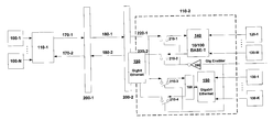
- FIG. 2 is a schematic representation of an embodiment for a Gigabit Ethernet capable 2 pair copper transmission line based serial backplane in accordance with an embodiment of the present invention.
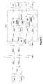
- FIG. 3 is a flowchart illustrating the communication process for two cards connected to serial backplane via the interface devices in the illustrative embodiment of the present invention.
- FIG. 1 schematically illustrates a typical conventional high speed Ethernet based serial backplane for a communication system, such as an SN 16000 optical switch from Sycamore Networks, Chelmsford, MASS.
- Two communication cards 10 - 1 and 10 - 2 are plugged into ports of 10/100 BASE-T interface devices 20 - 1 and 20 - 2 respectively and then connected to a serial backplane via two backplane connectors 60 and 70 .
- a communication card can be one of many field-replaceable microprocessor-based slave cards responsible for handling network traffic or it can be a field-replaceable microprocessor-based master card that is responsible for managing the slave cards.
- the backplane is the non-replaceable fixed medium by which the slave cards communicate with the master card.
- the backplane in FIG. 1 is delineated by the region between the backplane connectors 60 and 70 .
- interface device 20 - 1 for card 10 - 1 communicates with the serial backplane via 2 pairs 30 - 1 for transmit and 30 - 2 for receive
- interface device 20 - 2 for card 10 - 2 communicates with the serial backplane via two pairs 40 - 1 for receive and 40 - 2 for transmit.
- the span of backplane such as the distance between backplane connector 60 and 70 , is relatively short, normally in the range 2′′ to 40′′.
- the interface device can be a custom ASIC (application specific IC), or an off-the-shelf 10/100 Mbs Ethernet MAC (media access device) coupled with a 10/100BASE-T Ethernet Layer 1 transceiver.
- ASIC application specific IC
- Ethernet MAC media access device
- two interface devices 110 - 1 and 110 - 2 are located at two sides of a serial backplane, having 2 pair copper transmission lines 180 - 1 and 180 - 2 .
- the interface device can be one or more custom ASICs (application specific ICs), or an off-the-shelf 10/100/1000 Mbs Ethernet MAC (media access device) coupled with a 10/100BASE-T Ethernet Layer 1 transceiver (PHY) that also provides an IEEE 802.3z interface to which a SERDES can be connected.
- PHY 10/100BASE-T Ethernet Layer 1 transceiver
- a bank of analog switches or relays are used to switch between the serial interface on the SERDES and the 10/100BASE-T interface on the PHY.
- a plurality of cards 100 - 1 , . . . 100 -N are plugged into the interface device 110 - 1 via ports on the interface device 110 - 1 .
- a communication card can be one of many intelligent slave cards responsible for handling network traffic or it can be an intelligent master card that is responsible for managing the slave cards.
- a card that does not have a microprocessor on it is not an intelligent card and therefore is not a communication card.
- the interface device 110 - 1 is further connected to the backplane using 2 pair copper lines 170 - 1 for transmit and 170 - 2 for receive via backplane connector 200 - 1 .
- a detailed schematic of the same interface card 110 - 2 as 110 - 1 is described as in FIG.
- the Gigabit Enabler logic 190 controls the connection of either legacy 10/100 BASE-T interface 140 or Gigabit Ethernet interface 150 to serial backplane using 2 pair copper lines 220 - 1 for receive and 220 - 2 for transmit via backplane connector 200 - 2 .
- the Gigabit Enabler logic 190 functions by controlling switch mechanism 210 - 1 , 210 - 2 , 210 - 3 and 210 - 4 .
- the Gigabit Ethernet interface 150 is first connected to a Serdes interface 160 before switched to the 2 pair transmission lines 220 - 1 and 220 - 2 .
- the 10/100 BASE-T interface 140 , Gigabit Ethernet interface 150 and Serdes interface 160 can be implemented using Off the shelf products such as Intel's 82546 integrated dual MAC/PHY/SERDES device, or Broadcom's BCM5700 coupled with Broadcom's BCM5421S.
- FIG. 3 illustrates the communication process between two cards 100 - 1 (which is a new Gigabit Ethernet enabled card) and 120 - 1 (which is a legacy 100 BASE-T card).
- the default mode for card 100 - 1 and 120 - 1 are reset to the lowest Ethernet speed such as 10BASE-T or 100BASE-T.
- a first card such as 100 - 1 , initiates the contact with card 200 - 1 by first identifying card 200 - 1 's Gigabit capability.
- One way of doing this is by reading card 200 - 1 's identification stored in PROM, among many possible implementations.
- Card 100 - 1 starts negotiating for speed process by trying different speeds such as 10 Mbps, 100 Mbps, 1000 Mbps until the highest common speed between cards 100 - 1 and 120 - 1 is found.
- Card 100 - 1 and 100 - 2 default to 100BASE-T upon power-up. If card 100 - 1 is the master (management entity) and it is capable of Gig-E, it queries the slave or examines its ID PROM to determine this. If the Gig-E capable slave responds favorably to the query, the master switches to Gig-E and tries to establish communication. If the link drops as a result of either the master or slave being reset the interface resets to its default state (100BASE-T).
- the Gigabit enabler logic will switch either 10/100BASE-T or Gigabit Ethernet interface to the backplane via 2 pair copper transmission lines.
- the negotiated speed is 100BASE-T
- the Gigabit enabler logic on the left side will connect Gigabit Ethernet interface within 110 - 1 to the backplane
- the Gigabit enabler logic on the right side will connect 10/100BASE-T 140 interface within 110 - 2 to the backplane.
- the illustrated embodiment provides a seamless upgrade path to a Gigabit Ethernet for a legacy 2 pair copper transmission lines based serial backplane when next generation Gigabit Ethernet based cards come on line.
- the illustrated interface device with multiple Ethernet speed configurations allows next generation cards to be backward compatible with the legacy cards while both next generation and legacy cards coexist in the same system.
Abstract
An interface device having a plurality of ports with a plurality of speed configurations for a serial backplane with 2-pair copper transmission lines, has a plurality of high speed Ethernet ports and a plurality of Gigabit Ethernet ports. A switch mechanism for selecting between the high speed Ethernet ports and the Gigabit Ethernet ports will connect the selected port to the serial backplane via the 2-pair copper transmission lines.
Description
- Not Applicable.
- Not Applicable.
- This invention relates generally to serial backplane application and more particularly to apparatus and methods for seamlessly upgrading Ethernet to Gigabit Ethernet while allowing Gigabit Ethernet and Ethernet to coexist in the same system for a serial backplane with 2-pair copper transmission infrastructure.
- Typical telecom equipment such as SONET, SDH, ATM or Gigabit Ethernet switches use modular designs. Modules such as communication line cards are inserted in the sockets of an electronic circuit board to allow them to communicate with each other. The interface design of modules and backplanes constitute the “backbone” for the equipment. The backbone can be a traditional parallel mode bus with single-ended signaling, or a serialized interface with low voltage differential signaling. The topology of the backplane design can vary from point-to-point to multi-drop to multi-point connection.
- As the need for bandwidth expands in LANs, WANs and SANs, serial backplanes become the ideal alternative for solving information bottlenecks. The current use of parallel buses in networking systems does not provide the performance required. Serial backplanes have clear advantages over parallel buses in that they utilize fewer wires and connectors, consume less power, can carry signals for longer distances, and ultimately offer higher performance and reliability. This allows the designer to connect boards that are separated by larger distances, together in the system. In addition, wiring harnesses are simplified because the designer does not need to run a large number of wires (as in a parallel bus), when a single pair of wires (as in a serial backplane) can be employed. This results in lower costs and higher performance. High performance is also achieved because serial approaches generate less crosstalk between parallel wires.
- Many data communication vendors use 10BASE-T (10 Mbps) or 100BASE-T (100 Mbps) Ethernet as a communication channel between the different cards in a piece of telecom equipment. 10BASE-T or 100BASE-T form the communication channel among cards in the system. They do this by providing a physical link consisting of two pairs of signals routed on the backplane. One par of signals is used for the receive channel and one pair is used for the transmit channel. The 100BASE-T communications channel can be used for general card control, software maintenance, establishing in-band NMS (Network Management System) links and for alarm reporting. It is not used for processing or switching data. As the system grows and more cards are added, the bandwidth of the 10BASE-T or 100BASE-T channels gets consumed, thus slowing down the performance of the system.
- Gigabit Ethernet offers a solution to the problem. However the Gigabit Ethernet standard for transmission over copper, 1000BASE-T, requires four pairs of signals: two pairs of signals for transmit and two pairs for receive. It is very difficult and expensive to redesign the backplanes to accommodate this standard because of the installed customer base that would not be able to benefit from this enhancement. Replacing a backplane in the field would mean that the entire system would have to be replaced. Furthermore, it is desirable to stay backwards compatible with the existing installed legacy cards. This problem is not unique to a single system vendor because the standard for using four pairs of wires for 1000BASE-T was not formally completed when the backplanes for many system vendors were first designed. To differentiate Gigabit Ethernet from other versions of Ethernet, those versions of Ethernet that operate at or below 100 Mbps are classified as high-speed Ethernet.
- It would, therefore, be desirable to provide an interface device and method to seamlessly upgrade 2-pair copper transmission lines based serial backplane from Ethernet to Gigabit Ethernet while allowing both Ethernet and gigabit Ethernet based cards to coexist in the same system.
- The present invention provides an interface device and method to seamlessly upgrade 2-pair copper transmission lines based serial backplane from Ethernet to Gigabit Ethernet while allowing both Ethernet and gigabit Ethernet based cards to coexist in the same system.
- An interface device has a plurality of ports with a plurality of speed configurations for a serial backplane with 2-pair copper transmission lines. The interface device has a plurality of high speed Ethernet ports and a plurality of Gigabit Ethernet ports. A switch mechanism for selecting between the high speed Ethernet ports and the Gigabit Ethernet ports connects the selected port to the serial backplane via the 2-pair copper transmission lines.
- A serial backplane has 2-pair copper transmission lines having two interface devices. The interface devices have a plurality of communication cards with different Ethernet speed configurations connected via the ports. A communication method for two of the communication cards on each of two interface devices to communicate with each other across the serial backplane includes the following steps: a first card initiates contact with a second card via a negotiating method and then initiates the switching mechanisms to connect either a high speed Ethernet port or a Gigabit Ethernet port of the two cards to the serial backplane via the 2-pair copper transmission lines.
- The invention will be more fully understood from the following detailed description taken in conjunction with the accompanying drawings, in which:
- FIG. 1 is a schematic diagram of a typical conventional high speed Ethernet based serial backplane for a communication system.
- FIG. 2 is a schematic representation of an embodiment for a Gigabit Ethernet capable 2 pair copper transmission line based serial backplane in accordance with an embodiment of the present invention.
- FIG. 3 is a flowchart illustrating the communication process for two cards connected to serial backplane via the interface devices in the illustrative embodiment of the present invention.
- Referring to the drawings, FIG. 1 schematically illustrates a typical conventional high speed Ethernet based serial backplane for a communication system, such as an SN 16000 optical switch from Sycamore Networks, Chelmsford, MASS. Two communication cards 10-1 and 10-2 are plugged into ports of 10/100 BASE-T interface devices 20-1 and 20-2 respectively and then connected to a serial backplane via two
backplane connectors backplane connectors backplane connector - As the system grows and more cards are added, the bandwidth of the 10BASE-T or 100BASE-T channels gets consumed, thus slowing down the performance of the telecom device. Gigabit Ethernet offers a solution to the problem, however, the Gigabit Ethernet standard for transmission over copper, 1000BASE-T, requires four pairs of signals: two pairs of signals for transmit and two pairs for receive. Fortunately a Serdes (SERializer-DESerializer) interface provides a point-to-point path from parallel to serial that uses 2 pairs lines, which is ideal to connect with a 2 pair copper transmission lines based serial backplane. The higher the data rate, the shorter the transmission distance must be. This means that closer attention must be paid to data integrity. One reason for Gigabit Ethernet over Copper standard to use 4 pair transmission lines is to support relatively long distance (100 meters) so each pair equivalently carries data at a rate of 250 Mbps. For general serial backplane applications, due to the relatively short distance (around 40″), 2 pairs using a Serdes interface is sufficient to maintain data integrity.
- As illustrated in FIG. 2, in accordance with one aspect of the invention, two interface devices 110-1 and 110-2 are located at two sides of a serial backplane, having 2 pair copper transmission lines 180-1 and 180-2. The interface device can be one or more custom ASICs (application specific ICs), or an off-the-shelf 10/100/1000 Mbs Ethernet MAC (media access device) coupled with a 10/100BASE-T Ethernet Layer 1 transceiver (PHY) that also provides an IEEE 802.3z interface to which a SERDES can be connected. To complete the interface device, a bank of analog switches or relays are used to switch between the serial interface on the SERDES and the 10/100BASE-T interface on the PHY. A plurality of cards 100-1, . . . 100-N are plugged into the interface device 110-1 via ports on the interface device 110-1. A communication card can be one of many intelligent slave cards responsible for handling network traffic or it can be an intelligent master card that is responsible for managing the slave cards. A card that does not have a microprocessor on it is not an intelligent card and therefore is not a communication card. The interface device 110-1 is further connected to the backplane using 2 pair copper lines 170-1 for transmit and 170-2 for receive via backplane connector 200-1. A detailed schematic of the same interface card 110-2 as 110-1 is described as in FIG. 2, which further includes a traditional 10/100 BASE-
T interface 140 having a plurality of legacy cards 120-1, . . . 120-M connected, and aGigabit Ethernet interface 150 having a plurality of new Gigabit Ethernet capable cards 130-1, . . . 130-K connected. TheGigabit Enabler logic 190 controls the connection of either legacy 10/100 BASE-T interface 140 orGigabit Ethernet interface 150 to serial backplane using 2 pair copper lines 220-1 for receive and 220-2 for transmit via backplane connector 200-2. TheGigabit Enabler logic 190 functions by controlling switch mechanism 210-1, 210-2, 210-3 and 210-4. TheGigabit Ethernet interface 150 is first connected to aSerdes interface 160 before switched to the 2 pair transmission lines 220-1 and 220-2. The 10/100 BASE-T interface 140,Gigabit Ethernet interface 150 and Serdes interface 160 can be implemented using Off the shelf products such as Intel's 82546 integrated dual MAC/PHY/SERDES device, or Broadcom's BCM5700 coupled with Broadcom's BCM5421S. - To further demonstrate how the interface device works, FIG. 3 illustrates the communication process between two cards 100-1 (which is a new Gigabit Ethernet enabled card) and 120-1 (which is a
legacy 100 BASE-T card). First, the default mode for card 100-1 and 120-1 are reset to the lowest Ethernet speed such as 10BASE-T or 100BASE-T. Then a first card, such as 100-1, initiates the contact with card 200-1 by first identifying card 200-1's Gigabit capability. One way of doing this is by reading card 200-1's identification stored in PROM, among many possible implementations. Card 100-1 starts negotiating for speed process by trying different speeds such as 10 Mbps, 100 Mbps, 1000 Mbps until the highest common speed between cards 100-1 and 120-1 is found. Card 100-1 and 100-2 default to 100BASE-T upon power-up. If card 100-1 is the master (management entity) and it is capable of Gig-E, it queries the slave or examines its ID PROM to determine this. If the Gig-E capable slave responds favorably to the query, the master switches to Gig-E and tries to establish communication. If the link drops as a result of either the master or slave being reset the interface resets to its default state (100BASE-T). Depending on the negotiated speed, the Gigabit enabler logic will switch either 10/100BASE-T or Gigabit Ethernet interface to the backplane via 2 pair copper transmission lines. For the illustrated example, the negotiated speed is 100BASE-T, the Gigabit enabler logic on the left side will connect Gigabit Ethernet interface within 110-1 to the backplane and the Gigabit enabler logic on the right side will connect 10/100BASE-T 140 interface within 110-2 to the backplane. - The illustrated embodiment provides a seamless upgrade path to a Gigabit Ethernet for a legacy 2 pair copper transmission lines based serial backplane when next generation Gigabit Ethernet based cards come on line. The illustrated interface device with multiple Ethernet speed configurations allows next generation cards to be backward compatible with the legacy cards while both next generation and legacy cards coexist in the same system.
- Numerous modifications and alternative embodiments of the present invention will be apparent to those skilled in the art in view of the foregoing description. Accordingly, this description is to be construed as illustrative only and is for the purpose of teaching those skilled in the art the best mode for carrying out the present invention. Details of the structure may vary substantially without departing from the spirit of the invention, and exclusive use of all modifications that come within the scope of the appended claims is reserved. It is intended that the present invention be limited only to the extent required by the appended claims and the applicable rules of law.
Claims (12)
1. An interface having a plurality of ports with a plurality of speed configurations for a serial backplane with 2-pair copper transmission lines, comprising:
a plurality of high speed Ethernet ports;
a plurality of Gigabit Ethernet ports with a SERDES interface;
a switch mechanism for selecting between said high speed Ethernet ports and said Gigabit Ethernet ports and for connecting said selected port to said serial backplane via said 2-pair copper transmission lines.
2. The interface in claim 1 wherein said high speed Ethernet ports have a speed configuration of 10 b/s.
3. The interface in claim 1 wherein said high speed Ethernet ports have a speed configuration of 100 b/s.
4. The interface in claim 1 wherein said switch mechanism is an analog switch.
5. The interface in claim 1 wherein said switch mechanism is provided via relays.
6. The interface in claim 4 wherein the analog switch is a PHEMT (Pseudomorphic High Electron Mobility Transistor) switch.
7. In a device having a serial backplane with 2-pair copper transmission lines having two interface devices, said interface devices having a plurality of communication cards with either high speed Ethernet or Gigabit Ethernet speed configurations connected via said ports, a communication method for two of said communication cards on said each of two interface devices across said serial backplane, comprising steps of:
the first of said two cards initiating contact with the second of said two cards by a negotiating a highest common speed configuration among said two cards;
initiating said switching mechanisms to connect said two cards via said negotiated highest common speed configuration to said serial backplane via said 2-pair copper transmission lines.
8. The communication method in claim 7 wherein said negotiating method further comprising:
setting the default speed configurations for said two communication cards to high Ethernet speed;
the first of said two cards determining the common highest speed configuration for said two cards by trying different speeds in a continuous loop;
9. The method of claim 8 wherein the default speed is 10BASE-T.
10. The method of claim 8 wherein the default speed is 100BASE-T.
11. The method of claim 8 wherein the high speed Ethernet is 10 b/s.
12. The method of claim 8 wherein the high speed Ethernet is 100 b/s.
Priority Applications (1)
| Application Number | Priority Date | Filing Date | Title |
|---|---|---|---|
| US10/117,363 US20030191883A1 (en) | 2002-04-05 | 2002-04-05 | Interface for upgrading serial backplane application from ethernet to gigabit ethernet |
Applications Claiming Priority (1)
| Application Number | Priority Date | Filing Date | Title |
|---|---|---|---|
| US10/117,363 US20030191883A1 (en) | 2002-04-05 | 2002-04-05 | Interface for upgrading serial backplane application from ethernet to gigabit ethernet |
Publications (1)
| Publication Number | Publication Date |
|---|---|
| US20030191883A1 true US20030191883A1 (en) | 2003-10-09 |
Family
ID=28674180
Family Applications (1)
| Application Number | Title | Priority Date | Filing Date |
|---|---|---|---|
| US10/117,363 Abandoned US20030191883A1 (en) | 2002-04-05 | 2002-04-05 | Interface for upgrading serial backplane application from ethernet to gigabit ethernet |
Country Status (1)
| Country | Link |
|---|---|
| US (1) | US20030191883A1 (en) |
Cited By (28)
| Publication number | Priority date | Publication date | Assignee | Title |
|---|---|---|---|---|
| US20050147121A1 (en) * | 2003-12-29 | 2005-07-07 | Gary Burrell | Method and apparatus to double LAN service unit bandwidth |
| US20060013246A1 (en) * | 2004-07-13 | 2006-01-19 | International Business Machines Corporation | System, apparatus and method for gigabit ethernet communications over an IBM cabling system |
| DE102005053271A1 (en) * | 2005-11-08 | 2007-05-10 | Siemens Ag | Switching device for gigabit passive optical network-optical line termination, has transmission units with transmitting/receiving units that send/receive data packets at respective connectors of transmission unit, based on specific methods |
| US20090034550A1 (en) * | 2003-07-21 | 2009-02-05 | Dropps Frank R | Method and system for routing fibre channel frames |
| US20090123150A1 (en) * | 2003-07-21 | 2009-05-14 | Dropps Frank R | Method and system for power control of fibre channel switches |
| US20090168772A1 (en) * | 2003-07-21 | 2009-07-02 | Dropps Frank R | Lun based hard zoning in fibre channel switches |
| US20090290584A1 (en) * | 2003-07-21 | 2009-11-26 | Dropps Frank R | Method and system for configuring fibre channel ports |
| US20090296716A1 (en) * | 2003-07-21 | 2009-12-03 | Dropps Frank R | Method and system for programmable data dependant network routing |
| US20090296715A1 (en) * | 2004-07-20 | 2009-12-03 | Dropps Frank R | Method and system for programmable data dependant network routing |
| US20090316592A1 (en) * | 2003-07-21 | 2009-12-24 | Dropps Frank R | Method and system for selecting virtual lanes in fibre channel switches |
| US20100040074A1 (en) * | 2003-07-21 | 2010-02-18 | Dropps Frank R | Multi-speed cut through operation in fibre channel switches |
| US7684401B2 (en) | 2003-07-21 | 2010-03-23 | Qlogic, Corporation | Method and system for using extended fabric features with fibre channel switch elements |
| US20100128607A1 (en) * | 2003-07-21 | 2010-05-27 | Dropps Frank R | Method and system for buffer-to-buffer credit recovery in fibre channel systems using virtual and/or pseudo virtual lanes |
| US7729288B1 (en) | 2002-09-11 | 2010-06-01 | Qlogic, Corporation | Zone management in a multi-module fibre channel switch |
| US7760752B2 (en) | 2003-07-21 | 2010-07-20 | Qlogic, Corporation | Programmable pseudo virtual lanes for fibre channel systems |
| US7792115B2 (en) | 2003-07-21 | 2010-09-07 | Qlogic, Corporation | Method and system for routing and filtering network data packets in fibre channel systems |
| US7822057B2 (en) | 2004-07-20 | 2010-10-26 | Qlogic, Corporation | Method and system for keeping a fibre channel arbitrated loop open during frame gaps |
| US7894348B2 (en) | 2003-07-21 | 2011-02-22 | Qlogic, Corporation | Method and system for congestion control in a fibre channel switch |
| US7930377B2 (en) | 2004-04-23 | 2011-04-19 | Qlogic, Corporation | Method and system for using boot servers in networks |
| US20120134372A1 (en) * | 2010-11-29 | 2012-05-31 | Liang-Wei Huang | Network device and network connecting method |
| US20120236851A1 (en) * | 2011-03-14 | 2012-09-20 | Woodruff William C | Method and system for a high-speed backward-compatible ethernet connector |
| US8295299B2 (en) * | 2004-10-01 | 2012-10-23 | Qlogic, Corporation | High speed fibre channel switch element |
| US8824489B1 (en) * | 2011-04-26 | 2014-09-02 | Marvell International Ltd. | Physical layer (PHY) devices for use in automotive and industrial applications |
| CN106533995A (en) * | 2017-01-11 | 2017-03-22 | 深圳市立全鼎盛科技有限公司 | Gigabit switch supporting cross-equipment port isolation |
| CN112148082A (en) * | 2020-09-15 | 2020-12-29 | 上海航天计算机技术研究所 | Rocket-ground communication device of high-reliability carrier rocket |
| US11016924B2 (en) | 2018-03-01 | 2021-05-25 | Samsung Electronics Co., Ltd. | System and method for supporting multi-mode and/or multi-speed non-volatile memory (NVM) express (NVMe) over fabrics (NVMe-oF) devices |
| SE2051061A1 (en) * | 2020-09-10 | 2022-03-11 | Westermo Network Tech Ab | Ethernet network node |
| US11588261B2 (en) | 2018-03-09 | 2023-02-21 | Samsung Electronics Co., Ltd. | Multi-mode and/or multi-speed non-volatile memory (NVM) express (NVMe) over fabrics (NVMe-oF) device |
Citations (18)
| Publication number | Priority date | Publication date | Assignee | Title |
|---|---|---|---|---|
| US3854125A (en) * | 1971-06-15 | 1974-12-10 | Instrumentation Engineering | Automated diagnostic testing system |
| US3892925A (en) * | 1974-06-03 | 1975-07-01 | Ibm | Electric signal exchange switching arrangement |
| US5299193A (en) * | 1992-02-28 | 1994-03-29 | Texas Instruments Incorporated | Signal interface for coupling a network front end circuit to a network adapter circuit |
| US5771237A (en) * | 1996-01-23 | 1998-06-23 | Lite-On Communications Corp. | Multiple rate waveshaping technique for fast ethernet media driver |
| US5784573A (en) * | 1994-11-04 | 1998-07-21 | Texas Instruments Incorporated | Multi-protocol local area network controller |
| US5907566A (en) * | 1997-05-29 | 1999-05-25 | 3Com Corporation | Continuous byte-stream encoder/decoder using frequency increase and cyclic redundancy check |
| US5991303A (en) * | 1997-07-28 | 1999-11-23 | Conexant Systems, Inc. | Multi-rate switching physical device for a mixed communication rate ethernet repeater |
| US6094439A (en) * | 1997-08-15 | 2000-07-25 | Advanced Micro Devices, Inc. | Arrangement for transmitting high speed packet data from a media access controller across multiple physical links |
| US6104696A (en) * | 1998-07-08 | 2000-08-15 | Broadcom Corporation | Method for sending packets between trunk ports of network switches |
| US6188699B1 (en) * | 1997-12-11 | 2001-02-13 | Pmc-Sierra Ltd. | Multi-channel encoder/decoder |
| US6247063B1 (en) * | 1995-02-23 | 2001-06-12 | Fujitsu Limited | Network terminal equipment capable of accommodating plurality of communication control units |
| US6275501B1 (en) * | 1998-04-21 | 2001-08-14 | Hewlett-Packard Company | Media access controller capable of connecting to a serial physical layer device and a media independent interface (MII) physical layer device |
| US6343079B1 (en) * | 1999-10-12 | 2002-01-29 | Sprint Communications Company, L.P. | Autonomous multi-services card |
| US20020120732A1 (en) * | 2001-02-27 | 2002-08-29 | Lee Daniel Joseph | Open internet protocol services platform |
| US6486511B1 (en) * | 2001-08-30 | 2002-11-26 | Northrop Grumman Corporation | Solid state RF switch with high cutoff frequency |
| US6519253B1 (en) * | 1996-12-19 | 2003-02-11 | Lucent Technologies Inc. | Telecommunication equipment support of ISDN communication lines for high speed data transmission |
| US6560234B1 (en) * | 1999-03-17 | 2003-05-06 | At&T Corp. | Universal premises distribution platform |
| US6574228B1 (en) * | 1999-02-01 | 2003-06-03 | Motorola, Inc. | Communication system with physical interface and communication controller, and method |
-
2002
- 2002-04-05 US US10/117,363 patent/US20030191883A1/en not_active Abandoned
Patent Citations (18)
| Publication number | Priority date | Publication date | Assignee | Title |
|---|---|---|---|---|
| US3854125A (en) * | 1971-06-15 | 1974-12-10 | Instrumentation Engineering | Automated diagnostic testing system |
| US3892925A (en) * | 1974-06-03 | 1975-07-01 | Ibm | Electric signal exchange switching arrangement |
| US5299193A (en) * | 1992-02-28 | 1994-03-29 | Texas Instruments Incorporated | Signal interface for coupling a network front end circuit to a network adapter circuit |
| US5784573A (en) * | 1994-11-04 | 1998-07-21 | Texas Instruments Incorporated | Multi-protocol local area network controller |
| US6247063B1 (en) * | 1995-02-23 | 2001-06-12 | Fujitsu Limited | Network terminal equipment capable of accommodating plurality of communication control units |
| US5771237A (en) * | 1996-01-23 | 1998-06-23 | Lite-On Communications Corp. | Multiple rate waveshaping technique for fast ethernet media driver |
| US6519253B1 (en) * | 1996-12-19 | 2003-02-11 | Lucent Technologies Inc. | Telecommunication equipment support of ISDN communication lines for high speed data transmission |
| US5907566A (en) * | 1997-05-29 | 1999-05-25 | 3Com Corporation | Continuous byte-stream encoder/decoder using frequency increase and cyclic redundancy check |
| US5991303A (en) * | 1997-07-28 | 1999-11-23 | Conexant Systems, Inc. | Multi-rate switching physical device for a mixed communication rate ethernet repeater |
| US6094439A (en) * | 1997-08-15 | 2000-07-25 | Advanced Micro Devices, Inc. | Arrangement for transmitting high speed packet data from a media access controller across multiple physical links |
| US6188699B1 (en) * | 1997-12-11 | 2001-02-13 | Pmc-Sierra Ltd. | Multi-channel encoder/decoder |
| US6275501B1 (en) * | 1998-04-21 | 2001-08-14 | Hewlett-Packard Company | Media access controller capable of connecting to a serial physical layer device and a media independent interface (MII) physical layer device |
| US6104696A (en) * | 1998-07-08 | 2000-08-15 | Broadcom Corporation | Method for sending packets between trunk ports of network switches |
| US6574228B1 (en) * | 1999-02-01 | 2003-06-03 | Motorola, Inc. | Communication system with physical interface and communication controller, and method |
| US6560234B1 (en) * | 1999-03-17 | 2003-05-06 | At&T Corp. | Universal premises distribution platform |
| US6343079B1 (en) * | 1999-10-12 | 2002-01-29 | Sprint Communications Company, L.P. | Autonomous multi-services card |
| US20020120732A1 (en) * | 2001-02-27 | 2002-08-29 | Lee Daniel Joseph | Open internet protocol services platform |
| US6486511B1 (en) * | 2001-08-30 | 2002-11-26 | Northrop Grumman Corporation | Solid state RF switch with high cutoff frequency |
Cited By (40)
| Publication number | Priority date | Publication date | Assignee | Title |
|---|---|---|---|---|
| US7729288B1 (en) | 2002-09-11 | 2010-06-01 | Qlogic, Corporation | Zone management in a multi-module fibre channel switch |
| US20090123150A1 (en) * | 2003-07-21 | 2009-05-14 | Dropps Frank R | Method and system for power control of fibre channel switches |
| US7792115B2 (en) | 2003-07-21 | 2010-09-07 | Qlogic, Corporation | Method and system for routing and filtering network data packets in fibre channel systems |
| US20100040074A1 (en) * | 2003-07-21 | 2010-02-18 | Dropps Frank R | Multi-speed cut through operation in fibre channel switches |
| US20090034550A1 (en) * | 2003-07-21 | 2009-02-05 | Dropps Frank R | Method and system for routing fibre channel frames |
| US8005105B2 (en) | 2003-07-21 | 2011-08-23 | Qlogic, Corporation | Method and system for configuring fibre channel ports |
| US20090168772A1 (en) * | 2003-07-21 | 2009-07-02 | Dropps Frank R | Lun based hard zoning in fibre channel switches |
| US20090316592A1 (en) * | 2003-07-21 | 2009-12-24 | Dropps Frank R | Method and system for selecting virtual lanes in fibre channel switches |
| US20090290584A1 (en) * | 2003-07-21 | 2009-11-26 | Dropps Frank R | Method and system for configuring fibre channel ports |
| US7684401B2 (en) | 2003-07-21 | 2010-03-23 | Qlogic, Corporation | Method and system for using extended fabric features with fibre channel switch elements |
| US7894348B2 (en) | 2003-07-21 | 2011-02-22 | Qlogic, Corporation | Method and system for congestion control in a fibre channel switch |
| US7936771B2 (en) | 2003-07-21 | 2011-05-03 | Qlogic, Corporation | Method and system for routing fibre channel frames |
| US8081650B2 (en) | 2003-07-21 | 2011-12-20 | Qlogic, Corporation | Method and system for selecting virtual lanes in fibre channel switches |
| US20090296716A1 (en) * | 2003-07-21 | 2009-12-03 | Dropps Frank R | Method and system for programmable data dependant network routing |
| US20100128607A1 (en) * | 2003-07-21 | 2010-05-27 | Dropps Frank R | Method and system for buffer-to-buffer credit recovery in fibre channel systems using virtual and/or pseudo virtual lanes |
| US7822061B2 (en) | 2003-07-21 | 2010-10-26 | Qlogic, Corporation | Method and system for power control of fibre channel switches |
| US7760752B2 (en) | 2003-07-21 | 2010-07-20 | Qlogic, Corporation | Programmable pseudo virtual lanes for fibre channel systems |
| US9118586B2 (en) | 2003-07-21 | 2015-08-25 | Qlogic, Corporation | Multi-speed cut through operation in fibre channel switches |
| US8072988B2 (en) | 2003-07-21 | 2011-12-06 | Qlogic, Corporation | Method and system for buffer-to-buffer credit recovery in fibre channel systems using virtual and/or pseudo virtual lanes |
| US20050147121A1 (en) * | 2003-12-29 | 2005-07-07 | Gary Burrell | Method and apparatus to double LAN service unit bandwidth |
| US7573898B2 (en) * | 2003-12-29 | 2009-08-11 | Fujitsu Limited | Method and apparatus to double LAN service unit bandwidth |
| US7930377B2 (en) | 2004-04-23 | 2011-04-19 | Qlogic, Corporation | Method and system for using boot servers in networks |
| US20060013246A1 (en) * | 2004-07-13 | 2006-01-19 | International Business Machines Corporation | System, apparatus and method for gigabit ethernet communications over an IBM cabling system |
| US20090296715A1 (en) * | 2004-07-20 | 2009-12-03 | Dropps Frank R | Method and system for programmable data dependant network routing |
| US7822057B2 (en) | 2004-07-20 | 2010-10-26 | Qlogic, Corporation | Method and system for keeping a fibre channel arbitrated loop open during frame gaps |
| US8295299B2 (en) * | 2004-10-01 | 2012-10-23 | Qlogic, Corporation | High speed fibre channel switch element |
| US8774206B2 (en) | 2004-10-01 | 2014-07-08 | Qlogic, Corporation | High speed fibre channel switch element |
| DE102005053271B4 (en) * | 2005-11-08 | 2007-08-23 | Siemens Ag | Switching device and method for selecting a data transmission method on a recording device |
| DE102005053271A1 (en) * | 2005-11-08 | 2007-05-10 | Siemens Ag | Switching device for gigabit passive optical network-optical line termination, has transmission units with transmitting/receiving units that send/receive data packets at respective connectors of transmission unit, based on specific methods |
| US8897318B2 (en) * | 2010-11-29 | 2014-11-25 | Realtek Semiconductor Corp. | Network device and network connecting method |
| US20120134372A1 (en) * | 2010-11-29 | 2012-05-31 | Liang-Wei Huang | Network device and network connecting method |
| US8908715B2 (en) * | 2011-03-14 | 2014-12-09 | Broadcom Corporation | Method and system for a high-speed backward-compatible ethernet connector |
| US20120236851A1 (en) * | 2011-03-14 | 2012-09-20 | Woodruff William C | Method and system for a high-speed backward-compatible ethernet connector |
| US8824489B1 (en) * | 2011-04-26 | 2014-09-02 | Marvell International Ltd. | Physical layer (PHY) devices for use in automotive and industrial applications |
| CN106533995A (en) * | 2017-01-11 | 2017-03-22 | 深圳市立全鼎盛科技有限公司 | Gigabit switch supporting cross-equipment port isolation |
| US11016924B2 (en) | 2018-03-01 | 2021-05-25 | Samsung Electronics Co., Ltd. | System and method for supporting multi-mode and/or multi-speed non-volatile memory (NVM) express (NVMe) over fabrics (NVMe-oF) devices |
| US11588261B2 (en) | 2018-03-09 | 2023-02-21 | Samsung Electronics Co., Ltd. | Multi-mode and/or multi-speed non-volatile memory (NVM) express (NVMe) over fabrics (NVMe-oF) device |
| SE2051061A1 (en) * | 2020-09-10 | 2022-03-11 | Westermo Network Tech Ab | Ethernet network node |
| SE545962C2 (en) * | 2020-09-10 | 2024-03-26 | Westermo Network Tech Ab | Train ethernet network node for Gbit/s data transmission over 2-pair ethernet cable |
| CN112148082A (en) * | 2020-09-15 | 2020-12-29 | 上海航天计算机技术研究所 | Rocket-ground communication device of high-reliability carrier rocket |
Similar Documents
| Publication | Publication Date | Title |
|---|---|---|
| US20030191883A1 (en) | Interface for upgrading serial backplane application from ethernet to gigabit ethernet | |
| EP1838032B1 (en) | Inband management for power over ethernet midspans using an embedded switch | |
| US5574722A (en) | Protocol independent switch | |
| US7133416B1 (en) | Converting data signals in a multiple communication protocol system area network | |
| US5892926A (en) | Direct media independent interface connection system for network devices | |
| EP1454440B1 (en) | Method and apparatus for providing optimized high speed link utilization | |
| US7536566B2 (en) | System architecture for a power distribution network and method of operation | |
| US7957283B2 (en) | Multi-port ethernet transceiver | |
| US7243182B2 (en) | Configurable high-speed serial links between components of a network device | |
| US7945164B2 (en) | Multiple fiber optic gigabit ethernet links channelized over single optical link | |
| US9036653B2 (en) | PoE communication bus, interface, and protocol between PoE subsystem and PHY or switch subsystems | |
| US10797893B2 (en) | Single pair ethernet management interface | |
| WO2007053995A1 (en) | Atca backboard, hub board connecting with it and system thereof | |
| US20010009553A1 (en) | Dual speed end station and system | |
| CN108337577A (en) | A kind of integrated backboards of novel VPX | |
| US20020080781A1 (en) | Method and arrangement relating to data transmission | |
| US8245056B2 (en) | Unified bus architecture for PoE communication and control | |
| US6907008B1 (en) | Method for a network device inserted between point to point connected stations to automatically negotiate communication parameters between the stations | |
| US7533194B2 (en) | Multi-mode port in a network device for serial and network communication | |
| Valenčić et al. | Developments and current trends in Ethernet technology | |
| CN109218110A (en) | A kind of communication equipment and communication means | |
| WO1998037666A1 (en) | Method and apparatus for integrating multiple repeaters into a single collision domain | |
| Vaughan-Nichols | Will 10-Gigabit Ethernet have a bright future? | |
| EP2816788B1 (en) | Line processing unit and switch fabric system | |
| KR100613907B1 (en) | Ethernet port apparatus supporting multiple media and its media management method, and switching system its |
Legal Events
| Date | Code | Title | Description |
|---|---|---|---|
| AS | Assignment |
Owner name: SYCAMORE NETWORKS, INC., MASSACHUSETTS Free format text: ASSIGNMENT OF ASSIGNORS INTEREST;ASSIGNOR:APRIL, STEVEN J.;REEL/FRAME:012781/0360 Effective date: 20020403 |
|
| STCB | Information on status: application discontinuation |
Free format text: ABANDONED -- FAILURE TO RESPOND TO AN OFFICE ACTION |