US20030191498A1 - Method and apparatus for attaching connective tissues to bone using a cortical bone anchoring device - Google Patents
Method and apparatus for attaching connective tissues to bone using a cortical bone anchoring device Download PDFInfo
- Publication number
- US20030191498A1 US20030191498A1 US10/396,886 US39688603A US2003191498A1 US 20030191498 A1 US20030191498 A1 US 20030191498A1 US 39688603 A US39688603 A US 39688603A US 2003191498 A1 US2003191498 A1 US 2003191498A1
- Authority
- US
- United States
- Prior art keywords
- disk
- bone
- bone anchor
- recited
- tube
- Prior art date
- Legal status (The legal status is an assumption and is not a legal conclusion. Google has not performed a legal analysis and makes no representation as to the accuracy of the status listed.)
- Granted
Links
Images


Classifications
-
- A—HUMAN NECESSITIES
- A61—MEDICAL OR VETERINARY SCIENCE; HYGIENE
- A61B—DIAGNOSIS; SURGERY; IDENTIFICATION
- A61B17/00—Surgical instruments, devices or methods, e.g. tourniquets
- A61B17/56—Surgical instruments or methods for treatment of bones or joints; Devices specially adapted therefor
-
- A—HUMAN NECESSITIES
- A61—MEDICAL OR VETERINARY SCIENCE; HYGIENE
- A61F—FILTERS IMPLANTABLE INTO BLOOD VESSELS; PROSTHESES; DEVICES PROVIDING PATENCY TO, OR PREVENTING COLLAPSING OF, TUBULAR STRUCTURES OF THE BODY, e.g. STENTS; ORTHOPAEDIC, NURSING OR CONTRACEPTIVE DEVICES; FOMENTATION; TREATMENT OR PROTECTION OF EYES OR EARS; BANDAGES, DRESSINGS OR ABSORBENT PADS; FIRST-AID KITS
- A61F2/00—Filters implantable into blood vessels; Prostheses, i.e. artificial substitutes or replacements for parts of the body; Appliances for connecting them with the body; Devices providing patency to, or preventing collapsing of, tubular structures of the body, e.g. stents
- A61F2/02—Prostheses implantable into the body
- A61F2/08—Muscles; Tendons; Ligaments
- A61F2/0811—Fixation devices for tendons or ligaments
-
- A—HUMAN NECESSITIES
- A61—MEDICAL OR VETERINARY SCIENCE; HYGIENE
- A61B—DIAGNOSIS; SURGERY; IDENTIFICATION
- A61B17/00—Surgical instruments, devices or methods, e.g. tourniquets
- A61B17/04—Surgical instruments, devices or methods, e.g. tourniquets for suturing wounds; Holders or packages for needles or suture materials
- A61B17/0401—Suture anchors, buttons or pledgets, i.e. means for attaching sutures to bone, cartilage or soft tissue; Instruments for applying or removing suture anchors
- A61B2017/0409—Instruments for applying suture anchors
-
- A—HUMAN NECESSITIES
- A61—MEDICAL OR VETERINARY SCIENCE; HYGIENE
- A61B—DIAGNOSIS; SURGERY; IDENTIFICATION
- A61B17/00—Surgical instruments, devices or methods, e.g. tourniquets
- A61B17/04—Surgical instruments, devices or methods, e.g. tourniquets for suturing wounds; Holders or packages for needles or suture materials
- A61B17/0401—Suture anchors, buttons or pledgets, i.e. means for attaching sutures to bone, cartilage or soft tissue; Instruments for applying or removing suture anchors
- A61B2017/0414—Suture anchors, buttons or pledgets, i.e. means for attaching sutures to bone, cartilage or soft tissue; Instruments for applying or removing suture anchors having a suture-receiving opening, e.g. lateral opening
-
- A—HUMAN NECESSITIES
- A61—MEDICAL OR VETERINARY SCIENCE; HYGIENE
- A61B—DIAGNOSIS; SURGERY; IDENTIFICATION
- A61B17/00—Surgical instruments, devices or methods, e.g. tourniquets
- A61B17/04—Surgical instruments, devices or methods, e.g. tourniquets for suturing wounds; Holders or packages for needles or suture materials
- A61B17/0401—Suture anchors, buttons or pledgets, i.e. means for attaching sutures to bone, cartilage or soft tissue; Instruments for applying or removing suture anchors
- A61B2017/0446—Means for attaching and blocking the suture in the suture anchor
- A61B2017/0458—Longitudinal through hole, e.g. suture blocked by a distal suture knot
-
- A—HUMAN NECESSITIES
- A61—MEDICAL OR VETERINARY SCIENCE; HYGIENE
- A61F—FILTERS IMPLANTABLE INTO BLOOD VESSELS; PROSTHESES; DEVICES PROVIDING PATENCY TO, OR PREVENTING COLLAPSING OF, TUBULAR STRUCTURES OF THE BODY, e.g. STENTS; ORTHOPAEDIC, NURSING OR CONTRACEPTIVE DEVICES; FOMENTATION; TREATMENT OR PROTECTION OF EYES OR EARS; BANDAGES, DRESSINGS OR ABSORBENT PADS; FIRST-AID KITS
- A61F2/00—Filters implantable into blood vessels; Prostheses, i.e. artificial substitutes or replacements for parts of the body; Appliances for connecting them with the body; Devices providing patency to, or preventing collapsing of, tubular structures of the body, e.g. stents
- A61F2/02—Prostheses implantable into the body
- A61F2/08—Muscles; Tendons; Ligaments
- A61F2/0805—Implements for inserting tendons or ligaments
-
- A—HUMAN NECESSITIES
- A61—MEDICAL OR VETERINARY SCIENCE; HYGIENE
- A61F—FILTERS IMPLANTABLE INTO BLOOD VESSELS; PROSTHESES; DEVICES PROVIDING PATENCY TO, OR PREVENTING COLLAPSING OF, TUBULAR STRUCTURES OF THE BODY, e.g. STENTS; ORTHOPAEDIC, NURSING OR CONTRACEPTIVE DEVICES; FOMENTATION; TREATMENT OR PROTECTION OF EYES OR EARS; BANDAGES, DRESSINGS OR ABSORBENT PADS; FIRST-AID KITS
- A61F2/00—Filters implantable into blood vessels; Prostheses, i.e. artificial substitutes or replacements for parts of the body; Appliances for connecting them with the body; Devices providing patency to, or preventing collapsing of, tubular structures of the body, e.g. stents
- A61F2/02—Prostheses implantable into the body
- A61F2/08—Muscles; Tendons; Ligaments
- A61F2/0811—Fixation devices for tendons or ligaments
- A61F2002/0817—Structure of the anchor
- A61F2002/0823—Modular anchors comprising a plurality of separate parts
- A61F2002/0835—Modular anchors comprising a plurality of separate parts with deformation of anchor parts, e.g. expansion of dowel by set screw
-
- A—HUMAN NECESSITIES
- A61—MEDICAL OR VETERINARY SCIENCE; HYGIENE
- A61F—FILTERS IMPLANTABLE INTO BLOOD VESSELS; PROSTHESES; DEVICES PROVIDING PATENCY TO, OR PREVENTING COLLAPSING OF, TUBULAR STRUCTURES OF THE BODY, e.g. STENTS; ORTHOPAEDIC, NURSING OR CONTRACEPTIVE DEVICES; FOMENTATION; TREATMENT OR PROTECTION OF EYES OR EARS; BANDAGES, DRESSINGS OR ABSORBENT PADS; FIRST-AID KITS
- A61F2/00—Filters implantable into blood vessels; Prostheses, i.e. artificial substitutes or replacements for parts of the body; Appliances for connecting them with the body; Devices providing patency to, or preventing collapsing of, tubular structures of the body, e.g. stents
- A61F2/02—Prostheses implantable into the body
- A61F2/08—Muscles; Tendons; Ligaments
- A61F2/0811—Fixation devices for tendons or ligaments
- A61F2002/0847—Mode of fixation of anchor to tendon or ligament
- A61F2002/0864—Fixation of tendon or ligament between anchor elements, e.g. by additional screws in the anchor, anchor crimped around tendon
-
- A—HUMAN NECESSITIES
- A61—MEDICAL OR VETERINARY SCIENCE; HYGIENE
- A61F—FILTERS IMPLANTABLE INTO BLOOD VESSELS; PROSTHESES; DEVICES PROVIDING PATENCY TO, OR PREVENTING COLLAPSING OF, TUBULAR STRUCTURES OF THE BODY, e.g. STENTS; ORTHOPAEDIC, NURSING OR CONTRACEPTIVE DEVICES; FOMENTATION; TREATMENT OR PROTECTION OF EYES OR EARS; BANDAGES, DRESSINGS OR ABSORBENT PADS; FIRST-AID KITS
- A61F2/00—Filters implantable into blood vessels; Prostheses, i.e. artificial substitutes or replacements for parts of the body; Appliances for connecting them with the body; Devices providing patency to, or preventing collapsing of, tubular structures of the body, e.g. stents
- A61F2/02—Prostheses implantable into the body
- A61F2/08—Muscles; Tendons; Ligaments
- A61F2/0811—Fixation devices for tendons or ligaments
- A61F2002/0876—Position of anchor in respect to the bone
- A61F2002/0888—Anchor in or on a blind hole or on the bone surface without formation of a tunnel
Definitions
- This invention relates generally to methods and apparatus for attaching soft tissue to bone, and more particularly to anchors and methods for securing connective tissue, such as ligaments or tendons, to bone.
- the invention has particular application to arthroscopic surgical techniques for reattaching the rotator cuff to the humeral head, in order to repair the rotator cuff.
- tendons and other soft, connective tissues tear or to detach from associated bone.
- tear or detachment is a “rotator cuff” tear, wherein the supraspinatus tendon separates from the humerus, causing pain and loss of ability to elevate and externally rotate the arm. Complete separation can occur if the shoulder is subjected to gross trauma, but typically, the tear begins as a small lesion, especially in older patients.
- the humeral head is abraded or notched at the proposed soft tissue to bone reattachment point, as healing is enhanced on a raw bone surface.
- a series of small diameter holes referred to as “transosseous tunnels”, are “punched” through the bone laterally from the abraded or notched surface to a point on the outside surface of the greater tuberosity, commonly a distance of 2 to 3 cm.
- the cuff is sutured and secured to the bone by pulling the suture ends through the transosseous tunnels and tying them together using the bone between two successive tunnels as a bridge, after which the deltoid muscle must be surgically reattached to the acromion. Because of this maneuver, the deltoid requires postoperative protection, thus retarding rehabilitation and possibly resulting in residual weakness. Complete rehabilitation takes approximately 9 to 12 months.
- the mini-open technique which represents the current growing trend and the majority of all surgical repair procedures, differs from the classic approach by gaining access through a smaller incision and splitting rather than detaching the deltoid. Additionally, this procedure is typically performed in conjunction with arthroscopic acromial decompression.
- the deltoid is split, it is retracted to expose the rotator cuff tear. As before, the cuff is debrided, the humeral head is abraded, and the so-called “transosseous tunnels”, are “punched” through the bone or suture anchors are inserted. Following the suturing of the rotator cuff to the humeral head, the split deltoid is surgically repaired.
- knots tied arthroscopically are difficult to achieve, impossible to adjust, and are located in less than optimal areas of the shoulder. Suture tension is also impossible to measure and adjust once the knot has been fixed. Consequently, because of the technical difficulty of the procedure, presently less than 1% of all rotator cuff procedures are of the arthroscopic type, and are considered investigational in nature.
- Suture eyelets in bone anchors available today which like the eye of a needle are threaded with the thread or suture, are small in radius, and can cause the suture to fail at the eyelet when the anchor is placed under high tensile loads.
- Another approach is to utilize the difference in density in the cortical bone (the tough, dense outer layer of bone) and the cancellous bone (the less dense, airy and somewhat vascular interior of the bone).
- the cortical bone presents a kind of hard shell over the less dense cancellous bone.
- the aspect ratio of the anchor is such that it typically has a longer axis and a shorter axis and usually is pre-threaded with a suture.
- the hole is drilled such that the shorter axis of the anchor will fit through the diameter of the hole, with the longer axis of the anchor being parallel to the axis of the drilled hole.
- the anchor is rotated 90° so that the long axis is aligned perpendicularly to the axis of the hole.
- the suture is pulled, and the anchor is seated up against the inside surface of the cortical layer of bone. Due to the mismatch in the dimensions of the long axis of the anchor and the hole diameter, the anchor cannot be retracted proximally from the hole, thus providing resistance to pull-out.
- the anchor device uses stationary wing members which extend proximally and radially outward from the anchor member and which employ a cutting means along the wing members.
- the anchor device is inserted into a hole which has been drilled into the bone and then rotated radially such that the wing members with the cutting means are disposed into the cancellous layer of bone just below the cortical bone.
- a relatively small surface area of the wing members are disposed against the cortical bone in comparison with the present invention, making it more prone to being pulled out of the bone structure as proximal tension is applied to the suture.
- the Hayhurst patent further describes an approach to anchoring a suture to bone using an elongated anchor member shaped to normally assume a straight configuration which is then bent or flexed to allow it to be inserted through a needle or lumen and then expelled such that it returns to its straight configuration in a position generally perpendicular to the suture.
- This approach is designed for applications in which the anchor member may be placed between cartilage and bone and is impractical for use where the suture must be anchored directly to the bone—the applications for which the present invention is specifically designed.
- Bone anchor designs utilizing a means of disposing an anchoring device below the cortical bone in a generally parallel position to the cortical bone and in a perpendicular position to the suture are described in U.S. Pat. No. 5,941,900 to Bonutti and in U.S. Pat. No. 6,045,574 to Thal. These designs use a hole in the cortical bone through which an anchor is inserted. The hole is drilled such that the shorter axis of the anchor will fit through the diameter of the hole, with the longer axis of the anchor being parallel to the axis of the drilled hole.
- the anchor After deployment in to the cancellous bone, the anchor is rotated 90° so that the long axis is aligned perpendicularly to the axis of the hole. The suture is pulled, and the anchor is seated up against the inside surface of the cortical layer of bone. Due to the mismatch in the dimensions of the long axis of the anchor and the hole diameter, the anchor cannot be retracted proximally from the hole, thus providing resistance to pull-out.
- U.S. Pat. No. 6,146,406 to Shluzas et al. discloses a bone anchor having first and second anchoring legs and a bridge joining the anchoring legs between their proximal and distal ends. Portions of the anchoring legs on a proximal side of the bridge are configured to elastically compress together in response to an insertion force applied to the bone anchor during insertion of the bone anchor into a bone hole, and to plastically splay apart in response to a withdrawal force applied to the bone anchor, which force is applied by pulling on the suture extending proximally from the surgical site.
- This anchor also has a relatively limited surface area contact with the lower surface of the cortical bone and with the surrounding cancellous bone, and can be difficult and tricky to insert and deploy.
- the present invention overcomes the disadvantages of prior art devices and provides further advantages by utilizing the difference in density in the cortical bone (the tough, dense outer layer of bone) and the cancellous bone (the less dense, airy and somewhat vascular interior of the bone). There is a clear demarcation between the cortical bone and cancellous bone, where the cortical bone presents a kind of hard shell over the less dense cancellous bone.
- a major aspect of the present invention is to provide a means to either attach a suture securing device to the inventive anchoring device, or to attach a suture directly to the inventive device outside the body, then deploy the entire apparatus into the procedural area through a lumen in a tube. Once inserted into the procedural area within the bone, the device is expanded to anchor it beneath the cortical layer of bone. When the device is deployed, it extends radially into the cancellous bone just beneath the cortical layer of bone at the point at which the cortical and cancellous layers of bone meet. The manner in which the present invention is designed prevents it from returning, after it has been deployed, to the folded or bent profile it assumed as it was being deployed.
- This design moreover, prevents the invention from moving proximally due to the density of the cortical bone against which it is seated, or from moving either distally or radially due to the amount of anchor surface area which is extended into the cancellous bone.
- This approach is practicable for use in an arthroscopic procedure and eliminates the disadvantages associated with the use of screws, tacks, and staples described above.
- the present invention solves the problems outlined above by providing innovative bone anchor and connective techniques which permit a suture attachment which lies beneath the cortical bone surface, without the necessity of tying knots.
- a bone anchor device for attaching connective tissue to bone, which comprises disk adapted for insertion into a portion of bone.
- the disk is movable between a bent orientation for presenting a smaller cross-section and an expanded orientation for presenting a larger cross-section, and the disk is substantially planar when in the expanded orientation.
- the bent orientation is utilized for inserting the disk through a small hole into a region of cancellous bone beneath the cortical bone layer, after which the disk is actuated to move into its expanded orientation so that it will be permanently anchored in the cancellous bone, as it will be too large to return proximally through the hole in the cortical bone layer.
- the disk is generally elliptical when in the expanded orientation, and presents a generally circular footprint when in the bent orientation and viewed from a proximal position.
- the substantially planar disk is annular, comprising an annular sidewall and a center aperture.
- Such an embodiment is particularly useful with a separate suture retaining anchor disposed distally of the disk.
- Two axial suture receiving grooves disposed on an inner surface of the annular sidewall, spaced from one another by approximately 180 degrees, are preferably employed.
- the substantially planar disk is substantially solid, having two small apertures adjacent to one another in a center portion thereof for receiving suturing material therethrough.
- a slit is preferably disposed in the disk for facilitating the movement of the disk between the bent orientation and the expanded orientation, and, more preferably, two such slits, spaced approximately 180 degrees apart, are employed.
- the disk has a longitudinal axis extending between a proximal end and a distal end thereof, wherein the disk bends about an axis which lies transversely to the longitudinal axis.
- the disk forms a generally “V” shape in the bent orientation.
- each slit comprises an axial portion extending from the distal end of the disk, and a circumferential portion extending about a portion of an outer sidewall of the disk, wherein the circumferential portion is in communication with the axial portion so that the two slit portions together form each generally “T” shaped slit.
- a thin axial length of the sidewall extends between the proximal end of the disk and the circumferential slit portion. The disk bends about the transverse axis in a region including the thin axial length of each of the two slits.
- the disk is formed of flat stock resilient material, such as spring steel
- tension applied to opposing edges of the disk cause the bending to occur, because the natural orientation of the disk is its expanded planar configuration.
- the disk is formed from tubular stock, which is a non-resilient material, such as stainless steel
- an axial compressive force applied to the disk causes the bending to occur. In this configuration, the natural orientation of the disk is its bent, reduced configuration, and the axial compressive force is applied to force the disk to its expanded flat configuration.
- the disk has a thickness of approximately 0.031 inches and the thin axial length of the sidewall is approximately 0.006 inches long.
- it comprises spring stainless steel, and is biased by the spring stainless steel to assume the expanded orientation unless otherwise constrained.
- it comprises ordinary stainless steel or other suitable biocompatible material, and must be forced into the expanded orientation.
- a plurality of the aforementioned disks, arranged in a stacked array are employed.
- a bone anchor apparatus which comprises a first tube, a second tube coaxially and slidably disposed within the first tube, and a disk which is movable between a bent orientation for presenting a smaller cross-section and an expanded orientation for presenting a larger cross-section.
- the disk is disposed within the first tube distally of the second tube, in the aforementioned bent orientation, with a distal end of the second tube engaging the disk.
- tension applied to opposing edges of the disk by an inner wall of the first tube cause the bending to occur.
- the first tube comprises a proximal end portion having a first diameter and a distal end portion having a second diameter which is reduced relative to the first diameter.
- An axial length of the distal end portion is approximately equal to a thickness of cortical bone in a portion of bone into which the disk is to be disposed to function as a bone anchor, wherein a transition region on the tube between the proximal and distal end portions is adapted to function as a stop when the first tube is inserted into a hole in the bone portion, thereby ensuring that a distal end of the first tube is disposed in cancellous bone beneath the cortical bone thickness.
- a slit in an outer wall of the first tube which slit extends proximally from the distal end of the first tube proximally of the transition region.
- a slit in an outer wall of the second tube wherein the first and second tubes are rotationally oriented relative to one another, when the second tube is disposed within the first tube, so that the slits in each of the first and second tubes are substantially coincident with one another.
- a bone anchor apparatus which comprises an anchor body having a first displaceable portion and a second displaceable portion, together with a connecting portion which joins the first and second displaceable portions.
- the first and second displaceable portions are each moveable from a first orientation wherein portions of each of the first and second displaceable portions are disposed proximally of the connecting portion, and a second orientation wherein the first and second displaceable portions and the connecting portion all lie in substantially the same plane.
- the first and second displaceable portions in combination with the connecting portion comprise a disk, and a suture receiving groove is disposed in each of the first and second displaceable portions.
- the anchor body is initially disposed in the first orientation.
- a method for securing connective tissue to bone comprises steps of securing a first end of a length of suture to a portion of soft tissue to be attached to a portion of bone, and threading a second end of the length of suture through an aperture in a body of a bone anchor disk.
- the bone anchor disk is disposed within a lumen of a tube, with the disk being disposed in a bent orientation having a reduced cross-section.
- a distal end of the tube is inserted into a hole within the portion of bone.
- the disk is then deployed from the distal end of the tube. Once deployed, the disk moves to an expanded orientation, so that the disk becomes anchored within the portion of bone.
- a method of fabricating a bone anchor device comprises steps of providing a tube of biocompatible material, forming a bone anchor device by making a series of cuts on a first end of the tube, and separating the bone anchor device from a remaining portion of the tube by making a further cut through the tube.
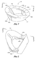
- FIG. 1 is a perspective view of a presently preferred embodiment of the inventive bone anchor device, shown in a fully expanded configuration
- FIG. 2 is a perspective view similar to that of FIG. 1, illustrating the inventive bone anchor device in a folded configuration
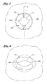
- FIG. 3 is a proximal plan view of the inventive bone anchor device wherein tension has been applied to each end of the device so that it is held in a circular profile;
- FIG. 4 is a proximal plan view of the inventive bone anchor device, similar to that of FIG. 3, wherein tension is no longer applied to each end of the device, so that it re-assumes an elliptical shape;
- FIG. 5 is a perspective view illustrating a preferred apparatus and method for inserting the inventive bone anchor device
- FIG. 6 is a schematic view, in cross-section, illustrating a preferred method for deploying the inventive bone anchor device
- FIG. 6A is a cross-sectional view of the area identified by the circle labeled 6 A in FIG. 6, showing insertion of the inventive bone anchor device into a suitable bone site;
- FIG. 6B is a cross-sectional view similar to FIG. 6A showing the bone anchor device after deployment;
- FIG. 7 is a perspective view of an alternative embodiment of the inventive anchor device, which may be utilized without an associated suture securing device;
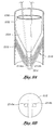
- FIG. 8 a is a plan view, in cross-section, of an alternative embodiment of the inventive anchor device, wherein a plurality of stacked elliptical disks are utilized rather than a single elliptical disk, as in the embodiments of FIGS. 1 - 7 ;
- FIG. 8 b is a top (proximal) view of the embodiment of FIG. 8 a;
- FIG. 9 a is plan view, similar to FIG. 8 a, of yet another alternative embodiment of the inventive anchor device.
- FIG. 9 b is a top (proximal) view of the embodiment of FIG. 9 a;
- FIG. 10 is a perspective view of a tube of suitable material for fabricating an embodiment of the inventive anchor device using an alternative fabrication method
- FIG. 11 is a perspective view similar to FIG. 10, illustrating the tube after a first fabrication step has been performed
- FIG. 12 is a perspective view similar to FIGS. 10 and 11 illustrating the tube after a second fabrication step has been performed;
- FIG. 13 is a perspective view similar to FIGS. 10 - 12 illustrating the tube after a third fabrication step has been performed;
- FIG. 14 is a perspective view from one end of the inventive anchor device fabricated from the tube shown in FIG. 10;
- FIG. 15 is a perspective view from the side of the inventive anchor device of FIG. 14.
- FIG. 1 a bone anchor 10 constructed in accordance with an embodiment of the present invention, comprised of an elliptical disk 12 with a generally circular aperture 14 in its center.
- the disk 12 is fabricated of flat stock, preferably 301 stainless spring steel, or other biocompatible equivalent material, and has a thickness of approximately 0.031 inches.
- First and second slits 16 a and 16 b, respectively, formed in a generally “T” shape when viewed from the side, are cut into each side of the annular disk from its distal end, using electro-discharge machining (EDM) techniques, or the like, and are spaced approximately 180 degrees from each other about the periphery of the disk.
- EDM electro-discharge machining
- the “T” shaped slits 16 a, b are cut entirely through the annular sidewall 17 of the disk 12 , and function to allow the disk to be bent in an upward or proximal direction for deployment into a portion of bone, as shall be more particularly described in connection with FIG. 2, below, and also to prevent “bend-back” when the disk returns to its flat or unfolded configuration (meaning that the slits will assist in preventing the disk from over-bending into a downward or distal direction as it returns to its unfolded configuration).
- the circular aperture 14 has first and second axially oriented grooves or channels 18 a and 18 b, respectively, in its inside surface 19 , which are preferably spaced approximately 180 degrees apart and are offset about 90 degrees from each slit 16 a, b.
- the aperture 14 permits the deployment of a suture securing apparatus into the desired bone structure distally through the inventive device, and also receives and permits passage of suture material therethrough.
- FIG. 2 the elliptical disk 12 has been bent upward or proximally into what might be described as a generally “V” shape by exerting tension on each end of the disk at locations about 90 degrees displaced from each of the “T” shaped slits 16 a, b.
- Such applied tension causes the thinner area 20 a, 20 b of the proximal end of the disk formed as a result of the presence of the T shaped slits 16 a, 16 b, which is preferably fabricated to have a thickness of approximately 0.006 inches from the proximal end of the T shaped slit to the proximal end of the disk 12 , to bend about an axis X (FIG. 3), which axis lies generally transversely to a longitudinal axis Y (FIG. 5) for as long as such tension is continually exerted.
- the spring-like action of the thinner profile formed at the proximal ends of such “T” shaped slits 16 a, b acts to cause the disk to return to its original flat profile.
- FIG. 3 is a proximal view of the inventive device as it appears with tension being applied to each end of the elliptical disk as described in connection with FIG. 2, above. It can be seen from FIG. 3 that applying such tension to the disk 12 causes it to be held in a circular profile. This circular profile allows the device to be inserted into a length of hypotubing for deployment arthroscopically into the desired surgical area by means of a trocar. The device is inserted through a length of hypotubing such that it is deployed at the juncture between the cancellous and cortical bone structures as shall be more fully illustrated hereinbelow.
- FIG. 4 is a proximal view of the inventive device as it appears once the referenced tension is no longer applied to each end of the elliptical disk 12 . It can be seen from FIG. 4 that once the tension is released, the disk 12 springs back to its original elliptical shape as viewed from a proximal direction as well as to its original flat profile as viewed from the side. As the disk 12 returns to its original profile, the two ends of the elliptical disk are pushed into the cancellous bone structure just below the point where the cancellous bone meets the cortical bone. When the disk 12 is returned to its original flat profile, its profile as viewed from a proximal direction returns from a round to an elliptical profile.
- the disk 12 is larger in cross-section than is the cross-sectional width of the hole in the bone structure into which it is inserted, such that the device 10 is anchored against the cortical bone in much the same way that a “moly” bolt becomes anchored within a wall or ceiling when it is radially expanded after insertion into the wall or ceiling through a drilled hole.
- the method by which the device is anchored to the bone structure shall be more fully described and illustrated in conjunction with FIGS. 5 & 6 below.
- a suture 24 is stitched in a suitable manner to the soft tissue to be repaired (preferably, a rotator cuff tendon, which is not shown in this figure).
- the stitching process may be accomplished by any known means, and any known suture stitch may be employed, the objective being to employ a secure stitch so that the suture is not inadvertently separated from the tendon after completion of the repair procedure, necessitating re-entry to the surgical site.
- the suture is attached to the soft tissue using a “mattress stitch”, which is well known in the art as being a particularly secure stitch which is unlikely to fail postoperatively.
- the preferred repair procedure discussed herein is an arthroscopic procedure, wherein an initial access incision is made to the repair site, and a trocar 25 is inserted into the access incision to provide access to the repair site for surgical instruments as well as optical instruments.
- a suturing instrument is inserted into the trocar to perform the aforementioned suturing step.
- the inventive device may also be utilized in an open surgical procedure, if desired, wherein the sutures are manually placed.
- the free ends 26 of the suture 24 are removed proximally through the trocar 25 from the patient's body, together with the suturing instrument.
- the free ends 26 of the suture 24 may then be attached to a suture anchoring device in the patient's body, which device may be integral with the bone anchor 10 or separate therefrom.
- a simple cylindrical suture anchoring device 28 through which the free ends 26 of the suture 24 have been threaded is shown.
- the free ends 26 of the suture 24 are threaded through the suture securing device 28 , they are threaded proximally through the aperture 14 in the bone anchor 10 .
- the grooves 18 a, 18 b are useful for receiving the suture which passes through the aperture 14 .
- the suture securing device 28 and bone anchor 10 are then inserted distally into a length of hypotubing 30 which includes a reduction in diameter at its distal end 31 so that its distal end is narrower than its proximal end 32 .
- the narrower distal end 31 of the hypo tube 30 is adapted to fit into a hole which has been drilled into the bone structure (not shown in FIG.
- the length of the narrower distal end 31 of the hypo tube 30 is predetermined to coincide with the approximate thickness of the outer cortical layer of bone, so that the portion of tubing which is stepped outwardly from the smaller diameter of the distal end of the tube to the larger diameter of the proximal end of the tube acts as a stop, thereby ensuring that the anchor 10 will be disposed at the approximate junction of cortical and cancellous bone.
- a slit 33 is disposed in the distal end of the hypotube 30 to allow the hypotube 30 to be inserted into the hole disposed in the bone without interfering with the bound end of the suture 24 which has been stitched through the rotator cuff.
- a mandrel 34 made from a narrower length of hypotubing than the notched hypotube 30 , is inserted distally into the hypotube 30 proximally from the bone anchor 10 .
- the mandrel 34 has a rounded distal end that fits into and engages the proximal end of the disk 12 when the disk 12 is held into the aforementioned generally “V” shape as a result of the tension applied to its ends by the inside wall of the hypotube 30 .
- a slit 35 is disposed in the distal end of the mandrel 34 , in alignment with the corresponding slit 33 in the hypotube 30 when the mandrel 34 is inserted coaxially into the hypotube 30 .
- the slits 35 and 33 function to prevent the apparatus from interfering with the bound ends of the suture 24 as the apparatus is inserted into the hole in the bone structure. It is noted that the free ends 26 of the suture 24 pass proximally from the suture securing device 28 , through the bone anchor 10 and mandrel 34 and out of the body, so that they may be manipulated by the practitioner performing the procedure.
- the entire apparatus consisting of the hypotube 30 with the suture securing device 28 , the bone anchor device 10 , and the mandrel device 34 , all disposed coaxially within the hypotube 30 , can now be inserted distally through the trocar 36 into the desired surgical site, such as, preferably, the shoulder of a patient.
- the mandrel 34 is pushed in a distal direction against the bone anchor 10 , pushing the bone anchor 10 out of the hypotube 30 and into the bone structure.
- the disk 12 returns from the generally “V” shaped profile exhibited while inside the hypotube 30 (FIGS. 2 and 3) to its original flat profile (FIGS. 1 and 4). This causes the ends of the elliptical disk 12 to push or dig into the soft cancellous bone just below the surface of the cortical bone layer.
- the hypotube 30 and mandrel 34 are removed through the trocar 25 out of the body.
- the free ends 26 of the suture 24 are then pulled in a proximal direction by the surgeon, in order to permit the soft tissue which is being reattached to adjacent bone structure to be adjusted positionally as necessary.
- This will also exert a distal force on the disk 12 , which force acts to secure the disk in position against the cortical bone and to further secure the disk in its flat profile.
- the flat profile of the disk 12 is larger than the diameter of the hole 42 , making it very difficult or impossible to pull the disk proximally out of the bone structure.
- FIGS. 6, 6A, and 6 B there is shown a cross-sectional view of a human shoulder 40 on the left side of the body as seen from the front of the body and which illustrates a rotator cuff tendon 44 which is disposed across a humeral head 46 .
- the rotator cuff tendon 44 is not attached to the humeral head 46 at the interface 48 between the two.
- the humeral head 46 is comprised of an outer surface of cortical bone 49 and inner cancellous bone 50 .
- the anchor 10 is utilized to assist in the repair of the shoulder 40 by reattachment of the rotator cuff tendon 44 to the humeral head 46 .
- a trocar 25 is first inserted into the shoulder in proximity to the area where the rotator cuff tendon 44 is to be reattached to the humeral head 46 , to allow for arthroscopic access.
- a hole 51 has been made, preferably by drilling or punching, in the desired location through the cortical bone 49 and into the cancellous bone 50 .
- the bone anchor 10 is shown in its fully deployed state.
- the disk 12 is in its original flat profile just below the cortical bone 49 and inserted into the cancellous bone 50 .
- the suture 24 is stitched through the rotator cuff tendon 44 , threaded through the suture securing device 28 , and the bone anchor 10 , and then the loose ends 26 of the suture 24 pass through the trocar 25 and out of the patient's body.
- Proximal tension may be applied by the practitioner to the free ends 26 of the suture 24 , to thereby secure the bone anchor device 10 against the cortical bone 49 and prevent the bone anchor device 10 from being removed from the bone structure.
- FIG. 7 illustrates an alternative embodiment of the present invention wherein the anchor device 10 may be utilized without any independent suture securing device, such as suture anchoring device 28 shown in FIGS. 5 and 6.
- the anchor device 10 may be utilized without any independent suture securing device, such as suture anchoring device 28 shown in FIGS. 5 and 6.
- two smaller apertures 14 a, 14 b are employed.
- a length of suture 24 may be threaded through the apertures 14 a, 14 b such that a portion 24 a of the suture 24 may be pulled snugly against a distal surface 52 of the disk 12 , thereby securing the suture to the disk 12 .
- the two free ends 26 of the suture 24 may be knotted or otherwise secured together proximally of the anchor device 1 and the excess suture may then be cut and removed.
- FIGS. 8 a and 8 b wherein like elements are designated by like reference numerals, preceded by the numeral “1”, a further alternative embodiment of the present invention is illustrated.
- a stack of elliptical springs or disks 112 are utilized in place of the single elliptical disk employed in the previous embodiments, to together form the bone anchor device 110 .
- the thickness of a single disk 112 approximately 0.031 inches in the preferred embodiments, is adequate to resist sufficient “pull-out” forces to be a useful anchor when used alone, but in certain applications it may be desirable to employ a stack of disks 112 in order to attain substantially greater resistance to pull-out forces.
- the elliptical springs 112 are held in a circular profile, like the single disk 12 in FIG. 2, by being inserted into a lumen 130 of a tube 132 , so that the tube forces the disks into the circular profile.
- the stack of disks 112 is pushed distally through the lumen 130 by a mandrel 134 and is thereby deployed at the distal edge of the cortical bone in the same manner as described in connection with the embodiment of FIGS. 5 and 6 above.
- This embodiment is intended to be deployed using a suture anchoring device 128 , as in FIG. 5, supra, though any type of suture attachment system could be employed if desired.
- FIG. 8 b shows a top view of the embodiment, illustrating the round profile of the elliptical springs in their undeployed state, while still within the lumen 130 .
- FIGS. 9 a and 9 b yet a third alternative embodiment is shown which is virtual identical to that shown in FIGS. 8 a and 8 b except that the device herein shown may be utilized without an independent suture securing device 128 as is the case with respect to the alternative embodiment shown in FIGS. 8 a and 8 b.
- like elements to those of FIGS. 1 - 8 b are designated by like reference numerals, preceded by the numeral “2”.
- the suture 224 is secured directly by the bone anchoring device 210 , by looping the suture through the suture holes 214 a and 214 b, as illustrated.
- FIGS. 10 - 15 illustrate an alternative and more cost effective method for fabricating a bone anchoring device of the type disclosed in this patent application.
- the bone anchor 310 as fabricated using the method of manufacturing to be described is similar in all respects to the bone anchor 10 as shown in FIGS. 1 - 7 , except that, since it is fabricated from tubing, rather than from flat stock, its natural orientation is the bent orientation similar to that shown in FIG. 2.
- an actuation device or the suture itself may be utilized to actuate the anchor 310 to its flat or unfolded deployed orientation.
- a tube 360 of suitable biocompatible material such as 300 series stainless steel, titanium, or carbon steel, and having a longitudinal axis 361 , is provided (FIG. 10).
- suitable biocompatible material such as 300 series stainless steel, titanium, or carbon steel
- opposing axial channels 362 a, 362 b, extending from a first end 363 of the tube 360 are formed.
- additional cuts 365 a - 365 d are made to remove material from the first end 363 of the tube 360 , as shown in FIG. 12.
- the final fabrication of the anchor 310 configuration is illustrated in FIG. 13, wherein additional cuts have been made as shown, and in FIG. 14, which illustrates the anchor 310 after it has been separated from the remainder of the tube 310 by the completion of cut 367 .
- the finished anchor 310 is substantially identical to the anchor 10 , although an entirely different fabrication technique has been utilized.
- the advantage of the methods described in connection with FIGS. 10 - 15 is a dramatically lower cost of production and a substantially increased rate of production.
- the reason for the reduced cost of production, other than, of course, the increased rate of production, which naturally reduces costs proportionately, is the ability to use cheaper materials, and to minimize material waste.
- the tube 360 may be utilized to fabricate a number of anchors 310 , and there is no need to use relatively expensive spring steel, because the natural orientation of the anchor 310 , because it is fabricated from tubing 360 , is the folded configuration shown in FIGS. 14 and 15.
- a deployment instrument or other suitable means may be used to move the anchor 310 proximally against the lower surface of the cortical bone. The force applied against the anchor 310 by the cortical bone as the anchor is moved proximally against it forces the anchor to bend into a substantially flat configuration, similar to that of FIG. 1, so that the anchor is permanently disposed within the bone to anchor the suture therein.
- One approach is to deploy the anchor to its extended or flat configuration using the suture itself, rather than a separate deployment instrument.
- the practitioner performing the procedure will pull the suture proximally, to approximate the soft tissue to the bone, as desired.
- the suture will exert a proximal force on the anchor 310 , thereby pushing it against the cortical bone and forcing its deployment to the deployed, substantially flat orientation.
Abstract
Description
- This invention relates generally to methods and apparatus for attaching soft tissue to bone, and more particularly to anchors and methods for securing connective tissue, such as ligaments or tendons, to bone. The invention has particular application to arthroscopic surgical techniques for reattaching the rotator cuff to the humeral head, in order to repair the rotator cuff.
- It is an increasingly common problem for tendons and other soft, connective tissues to tear or to detach from associated bone. One such type of tear or detachment is a “rotator cuff” tear, wherein the supraspinatus tendon separates from the humerus, causing pain and loss of ability to elevate and externally rotate the arm. Complete separation can occur if the shoulder is subjected to gross trauma, but typically, the tear begins as a small lesion, especially in older patients.
- To repair a torn rotator cuff, the typical course today is to do so surgically, through a large incision. This approach is presently taken in almost 99% of rotator cuff repair cases. There are two types of open surgical approaches for repair of the rotator cuff, one known as the “classic open” and the other as the “mini-open”. The classic open approach requires a large incision and complete detachment of the deltoid muscle from the acromion to facilitate exposure. The cuff is debrided to ensure suture attachment to viable tissue and to create a reasonable edge approximation. In addition, the humeral head is abraded or notched at the proposed soft tissue to bone reattachment point, as healing is enhanced on a raw bone surface. A series of small diameter holes, referred to as “transosseous tunnels”, are “punched” through the bone laterally from the abraded or notched surface to a point on the outside surface of the greater tuberosity, commonly a distance of 2 to 3 cm. Finally, the cuff is sutured and secured to the bone by pulling the suture ends through the transosseous tunnels and tying them together using the bone between two successive tunnels as a bridge, after which the deltoid muscle must be surgically reattached to the acromion. Because of this maneuver, the deltoid requires postoperative protection, thus retarding rehabilitation and possibly resulting in residual weakness. Complete rehabilitation takes approximately 9 to 12 months.
- The mini-open technique, which represents the current growing trend and the majority of all surgical repair procedures, differs from the classic approach by gaining access through a smaller incision and splitting rather than detaching the deltoid. Additionally, this procedure is typically performed in conjunction with arthroscopic acromial decompression. Once the deltoid is split, it is retracted to expose the rotator cuff tear. As before, the cuff is debrided, the humeral head is abraded, and the so-called “transosseous tunnels”, are “punched” through the bone or suture anchors are inserted. Following the suturing of the rotator cuff to the humeral head, the split deltoid is surgically repaired.
- Although the above described surgical techniques are the current standard of care for rotator cuff repair, they are associated with a great deal of patient discomfort and a lengthy recovery time, ranging from at least four months to one year or more. It is the above described manipulation of the deltoid muscle together with the large skin incision that causes the majority of patient discomfort and an increased recovery time.
- Less invasive arthroscopic techniques are beginning to be developed in an effort to address the shortcomings of open surgical repair. Working through small trocar portals that minimize disruption of the deltoid muscle, a few surgeons have been able to reattach the rotator cuff using various bone anchor and suture configurations. The rotator cuff is sutured intracorporeally and an anchor is driven into bone at a location appropriate for repair. Rather than thread the suture through transosseous tunnels which are difficult or impossible to create arthroscopically using current techniques, the repair is completed by tying the cuff down against bone using the anchor and suture. Early results of less invasive techniques are encouraging, with a substantial reduction in both patient recovery time and discomfort.
- Unfortunately, the skill level required to facilitate an entirely arthroscopic repair of the rotator cuff is inordinately high. Intracorporeal suturing is clumsy and time consuming, and only the simplest stitch patterns can be utilized. Extracorporeal knot tying is somewhat less difficult, but the tightness of the knots is difficult to judge, and the tension cannot later be adjusted. Also, because of the use of bone anchors to provide a suture fixation point in the bone, the knots that secure the soft tissues to the anchor by necessity leave the knot bundle on top of the soft tissues. In the case of rotator cuff repair, this means that the knot bundle is left in the shoulder capsule where it is able to be felt by the patient postoperatively when the patient exercises the shoulder joint. So, knots tied arthroscopically are difficult to achieve, impossible to adjust, and are located in less than optimal areas of the shoulder. Suture tension is also impossible to measure and adjust once the knot has been fixed. Consequently, because of the technical difficulty of the procedure, presently less than 1% of all rotator cuff procedures are of the arthroscopic type, and are considered investigational in nature.
- Another significant difficulty with current arthroscopic rotator cuff repair techniques are shortcomings related to currently available suture anchors. Suture eyelets in bone anchors available today, which like the eye of a needle are threaded with the thread or suture, are small in radius, and can cause the suture to fail at the eyelet when the anchor is placed under high tensile loads.
- There are various bone anchor designs available for use by an orthopedic surgeon for attachment of soft tissues to bone. The basic commonality between the designs is that they create an attachment point in the bone for a suture that may then be passed through the soft tissues and tied, thereby immobilizing the soft tissue. This attachment point may be accomplished by different means. Screws are known for creating such attachments, but suffer from a number of disadvantages, including their tendency to loosen over time, requiring a second procedure to later remove them, and their requirement for a relatively flat attachment geometry.
- Another approach is to utilize the difference in density in the cortical bone (the tough, dense outer layer of bone) and the cancellous bone (the less dense, airy and somewhat vascular interior of the bone). There is a clear demarcation between the cortical bone and cancellous bone, where the cortical bone presents a kind of hard shell over the less dense cancellous bone. The aspect ratio of the anchor is such that it typically has a longer axis and a shorter axis and usually is pre-threaded with a suture. These designs use a hole in the cortical bone through which an anchor is inserted. The hole is drilled such that the shorter axis of the anchor will fit through the diameter of the hole, with the longer axis of the anchor being parallel to the axis of the drilled hole. After deployment in to the cancellous bone, the anchor is rotated 90° so that the long axis is aligned perpendicularly to the axis of the hole. The suture is pulled, and the anchor is seated up against the inside surface of the cortical layer of bone. Due to the mismatch in the dimensions of the long axis of the anchor and the hole diameter, the anchor cannot be retracted proximally from the hole, thus providing resistance to pull-out. These anchors still suffer from the aforementioned problem of eyelet design that stresses the sutures.
- Still other prior art approaches have attempted to use a “pop rivet” approach. This type of design requires a hole in the cortical bone into which a split shaft is inserted. The split shaft is hollow, and has a tapered plug leading into its inner lumen. The tapered plug is extended out through the top of the shaft, and when the plug is retracted into the inner lumen, the tapered portion causes the split shaft to be flared outwardly, ostensibly locking the device into the bone.
- Other methods of securing soft tissue to bone are known in the prior art, but are not presently considered to be feasible for shoulder repair procedures, because of physicians' reluctance to leave anything but a suture in the capsule area of the shoulder. The reason for this is that staples, tacks, and the like could possibly fall out and cause injury during movement. As a result of this constraint, the attachment point often must be located at a less than ideal position. Also, the tacks or staples require a substantial hole in the soft tissue, and make it difficult for the surgeon to precisely locate the soft tissue relative to the bone.
- An approach that also utilizes the difference in density between the cortical and cancellous layers of bone is described in U.S. Pat. No. 5,618,314 to Harwin, et al. In that design, the anchor device uses stationary wing members which extend proximally and radially outward from the anchor member and which employ a cutting means along the wing members. In this approach, the anchor device is inserted into a hole which has been drilled into the bone and then rotated radially such that the wing members with the cutting means are disposed into the cancellous layer of bone just below the cortical bone. With this device, a relatively small surface area of the wing members are disposed against the cortical bone in comparison with the present invention, making it more prone to being pulled out of the bone structure as proximal tension is applied to the suture.
- A number of other various methods of anchoring a suture to bone utilizing the difference in density between the cortical and cancellous bone are described in U.S. Pat. No. 5,417,691 to Hayhurst. One such method describes an anchor with a series of proximally pointing barbs along its member, which is inserted, into a hole in the bone structure, utilizing the barbs as a means of anchoring the device to the bone. This method presents the same disadvantage with respect to the amount of surface area in contact with the bone as described in connection with the Harwin, et. al. patent, supra.
- The Hayhurst patent further describes an approach to anchoring a suture to bone using an elongated anchor member shaped to normally assume a straight configuration which is then bent or flexed to allow it to be inserted through a needle or lumen and then expelled such that it returns to its straight configuration in a position generally perpendicular to the suture. This approach is designed for applications in which the anchor member may be placed between cartilage and bone and is impractical for use where the suture must be anchored directly to the bone—the applications for which the present invention is specifically designed.
- Other similar approaches are described in U.S. Pat. No. 5,417,712 to Whittaker, et al. This patent describes anchor devices using various different barbs and wings to secure the anchor members to the bone. This approach, however, suffers the disadvantage of a small surface area disposed against the bone and a relatively weak construction and resultant anchoring interface.
- Bone anchor designs utilizing a means of disposing an anchoring device below the cortical bone in a generally parallel position to the cortical bone and in a perpendicular position to the suture are described in U.S. Pat. No. 5,941,900 to Bonutti and in U.S. Pat. No. 6,045,574 to Thal. These designs use a hole in the cortical bone through which an anchor is inserted. The hole is drilled such that the shorter axis of the anchor will fit through the diameter of the hole, with the longer axis of the anchor being parallel to the axis of the drilled hole. After deployment in to the cancellous bone, the anchor is rotated 90° so that the long axis is aligned perpendicularly to the axis of the hole. The suture is pulled, and the anchor is seated up against the inside surface of the cortical layer of bone. Due to the mismatch in the dimensions of the long axis of the anchor and the hole diameter, the anchor cannot be retracted proximally from the hole, thus providing resistance to pull-out.
- These anchors, however, do not have the ability to be bent or flexed for deployment through a narrow lumen or hypotube, making insertion and placement difficult. They also suffer from the same disadvantage of a small surface area to be disposed against the cortical bone as the other applications described above.
- U.S. Pat. No. 6,146,406 to Shluzas et al. discloses a bone anchor having first and second anchoring legs and a bridge joining the anchoring legs between their proximal and distal ends. Portions of the anchoring legs on a proximal side of the bridge are configured to elastically compress together in response to an insertion force applied to the bone anchor during insertion of the bone anchor into a bone hole, and to plastically splay apart in response to a withdrawal force applied to the bone anchor, which force is applied by pulling on the suture extending proximally from the surgical site. This anchor also has a relatively limited surface area contact with the lower surface of the cortical bone and with the surrounding cancellous bone, and can be difficult and tricky to insert and deploy.
- What is needed, therefore, is a new approach for repairing the rotator cuff or fixing other soft tissues to bone, wherein the suture resides completely below the cortical bone surface, there is no requirement for the surgeon to tie a knot to attach the suture to the bone anchor, and wherein the procedure associated with the new approach is better for the patient, saves time, is uncomplicated to use, and easily taught to practitioners having skill in the art.
- The present invention overcomes the disadvantages of prior art devices and provides further advantages by utilizing the difference in density in the cortical bone (the tough, dense outer layer of bone) and the cancellous bone (the less dense, airy and somewhat vascular interior of the bone). There is a clear demarcation between the cortical bone and cancellous bone, where the cortical bone presents a kind of hard shell over the less dense cancellous bone.
- A major aspect of the present invention is to provide a means to either attach a suture securing device to the inventive anchoring device, or to attach a suture directly to the inventive device outside the body, then deploy the entire apparatus into the procedural area through a lumen in a tube. Once inserted into the procedural area within the bone, the device is expanded to anchor it beneath the cortical layer of bone. When the device is deployed, it extends radially into the cancellous bone just beneath the cortical layer of bone at the point at which the cortical and cancellous layers of bone meet. The manner in which the present invention is designed prevents it from returning, after it has been deployed, to the folded or bent profile it assumed as it was being deployed. This design, moreover, prevents the invention from moving proximally due to the density of the cortical bone against which it is seated, or from moving either distally or radially due to the amount of anchor surface area which is extended into the cancellous bone. This approach is practicable for use in an arthroscopic procedure and eliminates the disadvantages associated with the use of screws, tacks, and staples described above. The present invention solves the problems outlined above by providing innovative bone anchor and connective techniques which permit a suture attachment which lies beneath the cortical bone surface, without the necessity of tying knots.
- More particularly, there is provided in a preferred embodiment a bone anchor device for attaching connective tissue to bone, which comprises disk adapted for insertion into a portion of bone. The disk is movable between a bent orientation for presenting a smaller cross-section and an expanded orientation for presenting a larger cross-section, and the disk is substantially planar when in the expanded orientation. The bent orientation is utilized for inserting the disk through a small hole into a region of cancellous bone beneath the cortical bone layer, after which the disk is actuated to move into its expanded orientation so that it will be permanently anchored in the cancellous bone, as it will be too large to return proximally through the hole in the cortical bone layer. The disk is generally elliptical when in the expanded orientation, and presents a generally circular footprint when in the bent orientation and viewed from a proximal position.
- In one preferred embodiment, the substantially planar disk is annular, comprising an annular sidewall and a center aperture. Such an embodiment is particularly useful with a separate suture retaining anchor disposed distally of the disk. Two axial suture receiving grooves disposed on an inner surface of the annular sidewall, spaced from one another by approximately 180 degrees, are preferably employed.
- In another embodiment, wherein the disk itself may be utilized as the suture retaining anchor, the substantially planar disk is substantially solid, having two small apertures adjacent to one another in a center portion thereof for receiving suturing material therethrough.
- A slit is preferably disposed in the disk for facilitating the movement of the disk between the bent orientation and the expanded orientation, and, more preferably, two such slits, spaced approximately 180 degrees apart, are employed. The disk has a longitudinal axis extending between a proximal end and a distal end thereof, wherein the disk bends about an axis which lies transversely to the longitudinal axis. The disk forms a generally “V” shape in the bent orientation. In a preferred embodiment, each slit comprises an axial portion extending from the distal end of the disk, and a circumferential portion extending about a portion of an outer sidewall of the disk, wherein the circumferential portion is in communication with the axial portion so that the two slit portions together form each generally “T” shaped slit. A thin axial length of the sidewall extends between the proximal end of the disk and the circumferential slit portion. The disk bends about the transverse axis in a region including the thin axial length of each of the two slits. In one embodiment, wherein the disk is formed of flat stock resilient material, such as spring steel, tension applied to opposing edges of the disk cause the bending to occur, because the natural orientation of the disk is its expanded planar configuration. In another embodiment, however, wherein the disk is formed from tubular stock, which is a non-resilient material, such as stainless steel, an axial compressive force applied to the disk causes the bending to occur. In this configuration, the natural orientation of the disk is its bent, reduced configuration, and the axial compressive force is applied to force the disk to its expanded flat configuration.
- In preferred embodiments, the disk has a thickness of approximately 0.031 inches and the thin axial length of the sidewall is approximately 0.006 inches long. As noted supra, in one embodiment, it comprises spring stainless steel, and is biased by the spring stainless steel to assume the expanded orientation unless otherwise constrained. In a second embodiment it comprises ordinary stainless steel or other suitable biocompatible material, and must be forced into the expanded orientation.
- In another embodiment, designed to substantially increase the pull-out strength of the anchor, a plurality of the aforementioned disks, arranged in a stacked array, are employed.
- In another aspect of the invention, there is provided a bone anchor apparatus, which comprises a first tube, a second tube coaxially and slidably disposed within the first tube, and a disk which is movable between a bent orientation for presenting a smaller cross-section and an expanded orientation for presenting a larger cross-section. During deployment of the bone anchor, the disk is disposed within the first tube distally of the second tube, in the aforementioned bent orientation, with a distal end of the second tube engaging the disk. In the spring steel embodiment, tension applied to opposing edges of the disk by an inner wall of the first tube cause the bending to occur. In a preferred embodiment, the first tube comprises a proximal end portion having a first diameter and a distal end portion having a second diameter which is reduced relative to the first diameter. An axial length of the distal end portion is approximately equal to a thickness of cortical bone in a portion of bone into which the disk is to be disposed to function as a bone anchor, wherein a transition region on the tube between the proximal and distal end portions is adapted to function as a stop when the first tube is inserted into a hole in the bone portion, thereby ensuring that a distal end of the first tube is disposed in cancellous bone beneath the cortical bone thickness.
- Preferably, there is disposed a slit in an outer wall of the first tube, which slit extends proximally from the distal end of the first tube proximally of the transition region. Additionally, there is a slit in an outer wall of the second tube, wherein the first and second tubes are rotationally oriented relative to one another, when the second tube is disposed within the first tube, so that the slits in each of the first and second tubes are substantially coincident with one another.
- In still another aspect of the invention, there is provided a bone anchor apparatus which comprises an anchor body having a first displaceable portion and a second displaceable portion, together with a connecting portion which joins the first and second displaceable portions. Advantageously, the first and second displaceable portions are each moveable from a first orientation wherein portions of each of the first and second displaceable portions are disposed proximally of the connecting portion, and a second orientation wherein the first and second displaceable portions and the connecting portion all lie in substantially the same plane. Preferably, the first and second displaceable portions in combination with the connecting portion comprise a disk, and a suture receiving groove is disposed in each of the first and second displaceable portions. In a presently preferred embodiment, the anchor body is initially disposed in the first orientation.
- In yet another aspect of the invention, there is disclosed a method for securing connective tissue to bone. The inventive method comprises steps of securing a first end of a length of suture to a portion of soft tissue to be attached to a portion of bone, and threading a second end of the length of suture through an aperture in a body of a bone anchor disk. The bone anchor disk is disposed within a lumen of a tube, with the disk being disposed in a bent orientation having a reduced cross-section. A distal end of the tube is inserted into a hole within the portion of bone. The disk is then deployed from the distal end of the tube. Once deployed, the disk moves to an expanded orientation, so that the disk becomes anchored within the portion of bone.
- In still another aspect of the invention, there is disclosed a method of fabricating a bone anchor device. The inventive method comprises steps of providing a tube of biocompatible material, forming a bone anchor device by making a series of cuts on a first end of the tube, and separating the bone anchor device from a remaining portion of the tube by making a further cut through the tube.
- The invention, together with additional features and advantages thereof, may best be understood by reference to the following description taken in conjunction with the accompanying illustrative drawing.
- FIG. 1 is a perspective view of a presently preferred embodiment of the inventive bone anchor device, shown in a fully expanded configuration;
- FIG. 2 is a perspective view similar to that of FIG. 1, illustrating the inventive bone anchor device in a folded configuration;
- FIG. 3 is a proximal plan view of the inventive bone anchor device wherein tension has been applied to each end of the device so that it is held in a circular profile;
- FIG. 4 is a proximal plan view of the inventive bone anchor device, similar to that of FIG. 3, wherein tension is no longer applied to each end of the device, so that it re-assumes an elliptical shape;
- FIG. 5 is a perspective view illustrating a preferred apparatus and method for inserting the inventive bone anchor device;
- FIG. 6 is a schematic view, in cross-section, illustrating a preferred method for deploying the inventive bone anchor device;
- FIG. 6A is a cross-sectional view of the area identified by the circle labeled 6A in FIG. 6, showing insertion of the inventive bone anchor device into a suitable bone site;
- FIG. 6B is a cross-sectional view similar to FIG. 6A showing the bone anchor device after deployment;
- FIG. 7 is a perspective view of an alternative embodiment of the inventive anchor device, which may be utilized without an associated suture securing device;
- FIG. 8 a is a plan view, in cross-section, of an alternative embodiment of the inventive anchor device, wherein a plurality of stacked elliptical disks are utilized rather than a single elliptical disk, as in the embodiments of FIGS. 1-7;
- FIG. 8 b is a top (proximal) view of the embodiment of FIG. 8a;
- FIG. 9 a is plan view, similar to FIG. 8a, of yet another alternative embodiment of the inventive anchor device;
- FIG. 9 b is a top (proximal) view of the embodiment of FIG. 9a;
- FIG. 10 is a perspective view of a tube of suitable material for fabricating an embodiment of the inventive anchor device using an alternative fabrication method;
- FIG. 11 is a perspective view similar to FIG. 10, illustrating the tube after a first fabrication step has been performed;
- FIG. 12 is a perspective view similar to FIGS. 10 and 11 illustrating the tube after a second fabrication step has been performed;
- FIG. 13 is a perspective view similar to FIGS. 10-12 illustrating the tube after a third fabrication step has been performed;
- FIG. 14 is a perspective view from one end of the inventive anchor device fabricated from the tube shown in FIG. 10; and
- FIG. 15 is a perspective view from the side of the inventive anchor device of FIG. 14.
- Referring now more particularly to the drawings, there is shown in FIG. 1 a
bone anchor 10 constructed in accordance with an embodiment of the present invention, comprised of anelliptical disk 12 with a generallycircular aperture 14 in its center. In this first embodiment, thedisk 12 is fabricated of flat stock, preferably 301 stainless spring steel, or other biocompatible equivalent material, and has a thickness of approximately 0.031 inches. First andsecond slits 16 a and 16 b, respectively, formed in a generally “T” shape when viewed from the side, are cut into each side of the annular disk from its distal end, using electro-discharge machining (EDM) techniques, or the like, and are spaced approximately 180 degrees from each other about the periphery of the disk. The “T” shaped slits 16 a, b are cut entirely through theannular sidewall 17 of thedisk 12, and function to allow the disk to be bent in an upward or proximal direction for deployment into a portion of bone, as shall be more particularly described in connection with FIG. 2, below, and also to prevent “bend-back” when the disk returns to its flat or unfolded configuration (meaning that the slits will assist in preventing the disk from over-bending into a downward or distal direction as it returns to its unfolded configuration). Thecircular aperture 14 has first and second axially oriented grooves orchannels inside surface 19, which are preferably spaced approximately 180 degrees apart and are offset about 90 degrees from each slit 16 a, b. Theaperture 14 permits the deployment of a suture securing apparatus into the desired bone structure distally through the inventive device, and also receives and permits passage of suture material therethrough. - In FIG. 2 the
elliptical disk 12 has been bent upward or proximally into what might be described as a generally “V” shape by exerting tension on each end of the disk at locations about 90 degrees displaced from each of the “T” shaped slits 16 a, b. Such applied tension, the application of which in the illustrated embodiment will be discussed in greater detail hereinbelow, causes thethinner area 20 a, 20 b of the proximal end of the disk formed as a result of the presence of the T shaped slits 16 a, 16 b, which is preferably fabricated to have a thickness of approximately 0.006 inches from the proximal end of the T shaped slit to the proximal end of thedisk 12, to bend about an axis X (FIG. 3), which axis lies generally transversely to a longitudinal axis Y (FIG. 5) for as long as such tension is continually exerted. When the tension is released, the spring-like action of the thinner profile formed at the proximal ends of such “T” shaped slits 16 a, b acts to cause the disk to return to its original flat profile. - FIG. 3 is a proximal view of the inventive device as it appears with tension being applied to each end of the elliptical disk as described in connection with FIG. 2, above. It can be seen from FIG. 3 that applying such tension to the
disk 12 causes it to be held in a circular profile. This circular profile allows the device to be inserted into a length of hypotubing for deployment arthroscopically into the desired surgical area by means of a trocar. The device is inserted through a length of hypotubing such that it is deployed at the juncture between the cancellous and cortical bone structures as shall be more fully illustrated hereinbelow. - FIG. 4 is a proximal view of the inventive device as it appears once the referenced tension is no longer applied to each end of the
elliptical disk 12. It can be seen from FIG. 4 that once the tension is released, thedisk 12 springs back to its original elliptical shape as viewed from a proximal direction as well as to its original flat profile as viewed from the side. As thedisk 12 returns to its original profile, the two ends of the elliptical disk are pushed into the cancellous bone structure just below the point where the cancellous bone meets the cortical bone. When thedisk 12 is returned to its original flat profile, its profile as viewed from a proximal direction returns from a round to an elliptical profile. Accordingly, with such a profile, thedisk 12 is larger in cross-section than is the cross-sectional width of the hole in the bone structure into which it is inserted, such that thedevice 10 is anchored against the cortical bone in much the same way that a “moly” bolt becomes anchored within a wall or ceiling when it is radially expanded after insertion into the wall or ceiling through a drilled hole. The method by which the device is anchored to the bone structure shall be more fully described and illustrated in conjunction with FIGS. 5 & 6 below. - Referring now to FIG. 5, a presently preferred apparatus by which the
bone anchor 10 is deployed into desired bone structure ( in the preferred case, a humeral head) to secure soft tissue to bone will be described. Initially, asuture 24, is stitched in a suitable manner to the soft tissue to be repaired (preferably, a rotator cuff tendon, which is not shown in this figure). The stitching process may be accomplished by any known means, and any known suture stitch may be employed, the objective being to employ a secure stitch so that the suture is not inadvertently separated from the tendon after completion of the repair procedure, necessitating re-entry to the surgical site. In preferred approaches, the suture is attached to the soft tissue using a “mattress stitch”, which is well known in the art as being a particularly secure stitch which is unlikely to fail postoperatively. - Of course, as discussed supra, the preferred repair procedure discussed herein is an arthroscopic procedure, wherein an initial access incision is made to the repair site, and a
trocar 25 is inserted into the access incision to provide access to the repair site for surgical instruments as well as optical instruments. Preferably, a suturing instrument is inserted into the trocar to perform the aforementioned suturing step. Of course, the inventive device may also be utilized in an open surgical procedure, if desired, wherein the sutures are manually placed. - Once the suturing process is completed, the free ends 26 of the
suture 24 are removed proximally through thetrocar 25 from the patient's body, together with the suturing instrument. The free ends 26 of thesuture 24 may then be attached to a suture anchoring device in the patient's body, which device may be integral with thebone anchor 10 or separate therefrom. The specifics of such suture anchoring systems are beyond the scope of the present invention, so, for the purposes of this description, a simple cylindricalsuture anchoring device 28 through which the free ends 26 of thesuture 24 have been threaded is shown. - Once the free ends 26 of the
suture 24 are threaded through thesuture securing device 28, they are threaded proximally through theaperture 14 in thebone anchor 10. Thegrooves aperture 14. Thesuture securing device 28 andbone anchor 10 are then inserted distally into a length ofhypotubing 30 which includes a reduction in diameter at itsdistal end 31 so that its distal end is narrower than itsproximal end 32. The narrowerdistal end 31 of thehypo tube 30 is adapted to fit into a hole which has been drilled into the bone structure (not shown in FIG. 5) such that the distal end of the hypotube will be disposed at a depth approximately equal to the depth of the cortical bone and cancellous bone interface. In other words, the length of the narrowerdistal end 31 of thehypo tube 30 is predetermined to coincide with the approximate thickness of the outer cortical layer of bone, so that the portion of tubing which is stepped outwardly from the smaller diameter of the distal end of the tube to the larger diameter of the proximal end of the tube acts as a stop, thereby ensuring that theanchor 10 will be disposed at the approximate junction of cortical and cancellous bone. Aslit 33 is disposed in the distal end of thehypotube 30 to allow thehypotube 30 to be inserted into the hole disposed in the bone without interfering with the bound end of thesuture 24 which has been stitched through the rotator cuff. - In one method of the present invention, a
mandrel 34, made from a narrower length of hypotubing than the notchedhypotube 30, is inserted distally into thehypotube 30 proximally from thebone anchor 10. Themandrel 34 has a rounded distal end that fits into and engages the proximal end of thedisk 12 when thedisk 12 is held into the aforementioned generally “V” shape as a result of the tension applied to its ends by the inside wall of thehypotube 30. Aslit 35 is disposed in the distal end of themandrel 34, in alignment with thecorresponding slit 33 in thehypotube 30 when themandrel 34 is inserted coaxially into thehypotube 30. Again, theslits suture 24 as the apparatus is inserted into the hole in the bone structure. It is noted that the free ends 26 of thesuture 24 pass proximally from thesuture securing device 28, through thebone anchor 10 andmandrel 34 and out of the body, so that they may be manipulated by the practitioner performing the procedure. - The entire apparatus, consisting of the
hypotube 30 with thesuture securing device 28, thebone anchor device 10, and themandrel device 34, all disposed coaxially within thehypotube 30, can now be inserted distally through the trocar 36 into the desired surgical site, such as, preferably, the shoulder of a patient. - To deploy the
bone anchor 10 through thehypotube 30, themandrel 34 is pushed in a distal direction against thebone anchor 10, pushing thebone anchor 10 out of thehypotube 30 and into the bone structure. When thebone anchor 10 is pushed completely out of thehypotube 30, so that tension is no longer applied to the ends of theelliptical disk 12 by the internal surface of thehypotube 30, thedisk 12 returns from the generally “V” shaped profile exhibited while inside the hypotube 30 (FIGS. 2 and 3) to its original flat profile (FIGS. 1 and 4). This causes the ends of theelliptical disk 12 to push or dig into the soft cancellous bone just below the surface of the cortical bone layer. - Once the
disk 12 along with thesuture securing device 28 have been inserted into the bone structure, thehypotube 30 andmandrel 34 are removed through thetrocar 25 out of the body. The free ends 26 of thesuture 24 are then pulled in a proximal direction by the surgeon, in order to permit the soft tissue which is being reattached to adjacent bone structure to be adjusted positionally as necessary. This will also exert a distal force on thedisk 12, which force acts to secure the disk in position against the cortical bone and to further secure the disk in its flat profile. As described in connection with FIG. 3, above, the flat profile of thedisk 12 is larger than the diameter of the hole 42, making it very difficult or impossible to pull the disk proximally out of the bone structure. - In FIGS. 6, 6A, and 6B, there is shown a cross-sectional view of a
human shoulder 40 on the left side of the body as seen from the front of the body and which illustrates arotator cuff tendon 44 which is disposed across ahumeral head 46. It is to be understood that, in this illustration, therotator cuff tendon 44 is not attached to thehumeral head 46 at theinterface 48 between the two. Thehumeral head 46 is comprised of an outer surface ofcortical bone 49 and innercancellous bone 50. In one method of use of the above describedinventive anchor 10 and associated apparatus, theanchor 10 is utilized to assist in the repair of theshoulder 40 by reattachment of therotator cuff tendon 44 to thehumeral head 46. - To that end, as described supra, a
trocar 25 is first inserted into the shoulder in proximity to the area where therotator cuff tendon 44 is to be reattached to thehumeral head 46, to allow for arthroscopic access. Ahole 51 has been made, preferably by drilling or punching, in the desired location through thecortical bone 49 and into thecancellous bone 50. This illustration is intended only to provide a simple structural overview of the physiological elements involved in a typical situation where it is to be desired that soft tissue such as therotator cuff tendon 44 be reattached to ahumeral head 46. - Referring in particular to FIG. 6B, the
bone anchor 10 is shown in its fully deployed state. Thedisk 12 is in its original flat profile just below thecortical bone 49 and inserted into thecancellous bone 50. Thesuture 24 is stitched through therotator cuff tendon 44, threaded through thesuture securing device 28, and thebone anchor 10, and then theloose ends 26 of thesuture 24 pass through thetrocar 25 and out of the patient's body. Proximal tension may be applied by the practitioner to the free ends 26 of thesuture 24, to thereby secure thebone anchor device 10 against thecortical bone 49 and prevent thebone anchor device 10 from being removed from the bone structure. - FIG. 7 illustrates an alternative embodiment of the present invention wherein the
anchor device 10 may be utilized without any independent suture securing device, such assuture anchoring device 28 shown in FIGS. 5 and 6. In this embodiment, rather than employing a singlecentral aperture 14, twosmaller apertures suture 24 may be threaded through theapertures portion 24 a of thesuture 24 may be pulled snugly against adistal surface 52 of thedisk 12, thereby securing the suture to thedisk 12. The twofree ends 26 of thesuture 24 may be knotted or otherwise secured together proximally of theanchor device 1 and the excess suture may then be cut and removed. - Referring now to FIGS. 8 a and 8 b, wherein like elements are designated by like reference numerals, preceded by the numeral “1”, a further alternative embodiment of the present invention is illustrated. In these figures it can be seen that a stack of elliptical springs or
disks 112 are utilized in place of the single elliptical disk employed in the previous embodiments, to together form thebone anchor device 110. It should be noted that the thickness of asingle disk 112, approximately 0.031 inches in the preferred embodiments, is adequate to resist sufficient “pull-out” forces to be a useful anchor when used alone, but in certain applications it may be desirable to employ a stack ofdisks 112 in order to attain substantially greater resistance to pull-out forces. Theelliptical springs 112 are held in a circular profile, like thesingle disk 12 in FIG. 2, by being inserted into alumen 130 of atube 132, so that the tube forces the disks into the circular profile. The stack ofdisks 112 is pushed distally through thelumen 130 by amandrel 134 and is thereby deployed at the distal edge of the cortical bone in the same manner as described in connection with the embodiment of FIGS. 5 and 6 above. This embodiment is intended to be deployed using asuture anchoring device 128, as in FIG. 5, supra, though any type of suture attachment system could be employed if desired. FIG. 8b shows a top view of the embodiment, illustrating the round profile of the elliptical springs in their undeployed state, while still within thelumen 130. - In FIGS. 9 a and 9 b, yet a third alternative embodiment is shown which is virtual identical to that shown in FIGS. 8a and 8 b except that the device herein shown may be utilized without an independent
suture securing device 128 as is the case with respect to the alternative embodiment shown in FIGS. 8a and 8 b. In this embodiment, as illustrated, like elements to those of FIGS. 1-8 b are designated by like reference numerals, preceded by the numeral “2”. Thesuture 224 is secured directly by thebone anchoring device 210, by looping the suture through the suture holes 214 a and 214 b, as illustrated. - FIGS. 10-15 illustrate an alternative and more cost effective method for fabricating a bone anchoring device of the type disclosed in this patent application. In general, the
bone anchor 310 as fabricated using the method of manufacturing to be described is similar in all respects to thebone anchor 10 as shown in FIGS. 1-7, except that, since it is fabricated from tubing, rather than from flat stock, its natural orientation is the bent orientation similar to that shown in FIG. 2. Once it has been inserted into suitable bone, an actuation device or the suture itself may be utilized to actuate theanchor 310 to its flat or unfolded deployed orientation. - More particularly, to fabricate the
anchor 310 in accordance with the inventive method, atube 360 of suitable biocompatible material, such as 300 series stainless steel, titanium, or carbon steel, and having alongitudinal axis 361, is provided (FIG. 10). As shown in FIG. 11, using EDM or other suitable cutting techniques, known to those skilled in the art, opposingaxial channels first end 363 of thetube 360, are formed. Following this, additional cuts 365 a-365 d are made to remove material from thefirst end 363 of thetube 360, as shown in FIG. 12. The final fabrication of theanchor 310 configuration is illustrated in FIG. 13, wherein additional cuts have been made as shown, and in FIG. 14, which illustrates theanchor 310 after it has been separated from the remainder of thetube 310 by the completion ofcut 367. - As is apparent from a comparison of FIGS. 2 and 15, the
finished anchor 310 is substantially identical to theanchor 10, although an entirely different fabrication technique has been utilized. The advantage of the methods described in connection with FIGS. 10-15 is a dramatically lower cost of production and a substantially increased rate of production. The reason for the reduced cost of production, other than, of course, the increased rate of production, which naturally reduces costs proportionately, is the ability to use cheaper materials, and to minimize material waste. Thetube 360 may be utilized to fabricate a number ofanchors 310, and there is no need to use relatively expensive spring steel, because the natural orientation of theanchor 310, because it is fabricated fromtubing 360, is the folded configuration shown in FIGS. 14 and 15. Thus, there is no need to bend theanchor 310 in order to insert it into the procedural site using theinsertion tube 30. Accordingly, there is no need to utilize a material which is capable of expanding back into its natural state once it has been bent. In contrast, once theanchor 310 is properly positioned within the desired bone site, below the cortical bone layer, a deployment instrument or other suitable means may be used to move theanchor 310 proximally against the lower surface of the cortical bone. The force applied against theanchor 310 by the cortical bone as the anchor is moved proximally against it forces the anchor to bend into a substantially flat configuration, similar to that of FIG. 1, so that the anchor is permanently disposed within the bone to anchor the suture therein. - One approach is to deploy the anchor to its extended or flat configuration using the suture itself, rather than a separate deployment instrument. Thus, as discussed supra in conjunction with the FIG. 1 embodiment, once the
anchor 310 is in place just beneath the cortical bone, the practitioner performing the procedure will pull the suture proximally, to approximate the soft tissue to the bone, as desired. As the suture is pulled proximally, it will exert a proximal force on theanchor 310, thereby pushing it against the cortical bone and forcing its deployment to the deployed, substantially flat orientation. - It is to be understood that the figures of the bone and anchors seen above are purely illustrative in nature, and are not intended to perfectly reproduce the physiologic and anatomic nature of the humeral head as expected to be seen in the human species, nor to limit the application of the inventive embodiments to repair of the rotator cuff. The invention is applicable to many different types of procedures involving, in particular, the attachment of connective or soft tissue to bone. Accordingly, although an exemplary embodiment of the invention has been shown and described, it is to be understood that all the terms used herein are descriptive rather than limiting, and that many changes, modifications, and substitutions may be made by one having ordinary skill in the art without departing from the spirit and scope of the invention.
Claims (40)
Priority Applications (1)
| Application Number | Priority Date | Filing Date | Title |
|---|---|---|---|
| US10/396,886 US7674274B2 (en) | 2001-06-06 | 2003-03-25 | Method and apparatus for attaching connective tissues to bone using a cortical bone anchoring device |
Applications Claiming Priority (2)
| Application Number | Priority Date | Filing Date | Title |
|---|---|---|---|
| US09/876,260 US6547800B2 (en) | 2001-06-06 | 2001-06-06 | Method and apparatus for attaching connective tissues to bone using a cortical bone anchoring device |
| US10/396,886 US7674274B2 (en) | 2001-06-06 | 2003-03-25 | Method and apparatus for attaching connective tissues to bone using a cortical bone anchoring device |
Related Parent Applications (1)
| Application Number | Title | Priority Date | Filing Date |
|---|---|---|---|
| US09/876,260 Continuation US6547800B2 (en) | 2001-06-06 | 2001-06-06 | Method and apparatus for attaching connective tissues to bone using a cortical bone anchoring device |
Publications (2)
| Publication Number | Publication Date |
|---|---|
| US20030191498A1 true US20030191498A1 (en) | 2003-10-09 |
| US7674274B2 US7674274B2 (en) | 2010-03-09 |
Family
ID=25367293
Family Applications (2)
| Application Number | Title | Priority Date | Filing Date |
|---|---|---|---|
| US09/876,260 Expired - Lifetime US6547800B2 (en) | 2001-06-06 | 2001-06-06 | Method and apparatus for attaching connective tissues to bone using a cortical bone anchoring device |
| US10/396,886 Expired - Fee Related US7674274B2 (en) | 2001-06-06 | 2003-03-25 | Method and apparatus for attaching connective tissues to bone using a cortical bone anchoring device |
Family Applications Before (1)
| Application Number | Title | Priority Date | Filing Date |
|---|---|---|---|
| US09/876,260 Expired - Lifetime US6547800B2 (en) | 2001-06-06 | 2001-06-06 | Method and apparatus for attaching connective tissues to bone using a cortical bone anchoring device |
Country Status (6)
| Country | Link |
|---|---|
| US (2) | US6547800B2 (en) |
| EP (1) | EP1392187A4 (en) |
| JP (1) | JP4299120B2 (en) |
| KR (1) | KR20040016874A (en) |
| CA (1) | CA2448406C (en) |
| WO (1) | WO2002098279A2 (en) |
Cited By (18)
| Publication number | Priority date | Publication date | Assignee | Title |
|---|---|---|---|---|
| US20040236336A1 (en) * | 2001-06-07 | 2004-11-25 | Opus Medical, Inc. | Method and apparatus for attaching connective tissues to bone using a suture anchoring device |
| US20060271060A1 (en) * | 2005-05-26 | 2006-11-30 | Arthrocare Corporation | Threaded knotless suture anchoring device and method |
| US7682374B2 (en) | 2003-10-21 | 2010-03-23 | Arthrocare Corporation | Knotless suture lock and bone anchor implant method |
| US7695494B2 (en) | 2001-02-12 | 2010-04-13 | Arthrocare Corporation | Method and apparatus for attaching connective tissues to bone using a knotless suture anchoring device |
| US8062334B2 (en) | 2004-06-02 | 2011-11-22 | Kfx Medical Corporation | Suture anchor |
| US8100942B1 (en) | 2004-06-02 | 2012-01-24 | Kfx Medical Corporation | System and method for attaching soft tissue to bone |
| US8109966B2 (en) | 1999-12-30 | 2012-02-07 | Arthrocare Corporation | Methods for attaching connective tissues to bone using a multi-component anchor |
| US8523902B2 (en) | 2009-01-30 | 2013-09-03 | Kfx Medical Corporation | System and method for attaching soft tissue to bone |
| US20140074160A1 (en) * | 2012-09-11 | 2014-03-13 | Biomet Sports Medicine, Llc | Flexible Planar Member For Tissue Fixation |
| US8801755B2 (en) | 2004-04-06 | 2014-08-12 | Arthrex, Inc. | Suture anchor |
| US8821541B2 (en) | 1999-02-02 | 2014-09-02 | Arthrex, Inc. | Suture anchor with insert-molded rigid member |
| US9044313B2 (en) | 2010-10-08 | 2015-06-02 | Kfx Medical Corporation | System and method for securing tissue to bone |
| US9179907B2 (en) | 2000-06-22 | 2015-11-10 | Arthrex, Inc. | Knotless graft fixation assembly |
| US9521999B2 (en) | 2005-09-13 | 2016-12-20 | Arthrex, Inc. | Fully-threaded bioabsorbable suture anchor |
| US9775597B2 (en) | 2011-10-04 | 2017-10-03 | Conmed Corporation | Dual expansion anchor |
| US9826970B2 (en) | 2009-10-13 | 2017-11-28 | Conmed Corporation | System and method for securing tissue to bone |
| US9936940B2 (en) | 2013-06-07 | 2018-04-10 | Biomet Sports Medicine, Llc | Method and apparatus for coupling soft tissue to bone |
| US9968349B2 (en) | 2011-04-13 | 2018-05-15 | Conmed Corporation | System and method for securing tissue to bone |
Families Citing this family (141)
| Publication number | Priority date | Publication date | Assignee | Title |
|---|---|---|---|---|
| US7615076B2 (en) | 1999-10-20 | 2009-11-10 | Anulex Technologies, Inc. | Method and apparatus for the treatment of the intervertebral disc annulus |
| US7004970B2 (en) | 1999-10-20 | 2006-02-28 | Anulex Technologies, Inc. | Methods and devices for spinal disc annulus reconstruction and repair |
| US8128698B2 (en) | 1999-10-20 | 2012-03-06 | Anulex Technologies, Inc. | Method and apparatus for the treatment of the intervertebral disc annulus |
| US8632590B2 (en) | 1999-10-20 | 2014-01-21 | Anulex Technologies, Inc. | Apparatus and methods for the treatment of the intervertebral disc |
| US7083638B2 (en) * | 2001-02-12 | 2006-08-01 | Arthrocare Corporation | Method and apparatus for attaching connective tissues to bone using a knotless suture anchoring device |
| US7280865B2 (en) * | 2001-12-20 | 2007-10-09 | Accuray Incorporated | Anchored fiducial apparatus and method |
| GB0208667D0 (en) * | 2002-04-16 | 2002-05-29 | Atlantech Medical Devices Ltd | A transverse suspension device |
| WO2005069924A2 (en) | 2004-01-16 | 2005-08-04 | Arthrocare Corporation | Bone harvesting device and method |
| US7608092B1 (en) | 2004-02-20 | 2009-10-27 | Biomet Sports Medicince, LLC | Method and apparatus for performing meniscus repair |
| WO2005112788A2 (en) * | 2004-05-17 | 2005-12-01 | Arthrocare Corporation | Bone anchor |
| US8137382B2 (en) | 2004-11-05 | 2012-03-20 | Biomet Sports Medicine, Llc | Method and apparatus for coupling anatomical features |
| US20060189993A1 (en) | 2004-11-09 | 2006-08-24 | Arthrotek, Inc. | Soft tissue conduit device |
| US7658751B2 (en) | 2006-09-29 | 2010-02-09 | Biomet Sports Medicine, Llc | Method for implanting soft tissue |
| US7905903B2 (en) | 2006-02-03 | 2011-03-15 | Biomet Sports Medicine, Llc | Method for tissue fixation |
| US8118836B2 (en) | 2004-11-05 | 2012-02-21 | Biomet Sports Medicine, Llc | Method and apparatus for coupling soft tissue to a bone |
| US7749250B2 (en) | 2006-02-03 | 2010-07-06 | Biomet Sports Medicine, Llc | Soft tissue repair assembly and associated method |
| US7909851B2 (en) | 2006-02-03 | 2011-03-22 | Biomet Sports Medicine, Llc | Soft tissue repair device and associated methods |
| US9017381B2 (en) | 2007-04-10 | 2015-04-28 | Biomet Sports Medicine, Llc | Adjustable knotless loops |
| US8298262B2 (en) | 2006-02-03 | 2012-10-30 | Biomet Sports Medicine, Llc | Method for tissue fixation |
| US8840645B2 (en) | 2004-11-05 | 2014-09-23 | Biomet Sports Medicine, Llc | Method and apparatus for coupling soft tissue to a bone |
| US7857830B2 (en) | 2006-02-03 | 2010-12-28 | Biomet Sports Medicine, Llc | Soft tissue repair and conduit device |
| US7905904B2 (en) | 2006-02-03 | 2011-03-15 | Biomet Sports Medicine, Llc | Soft tissue repair device and associated methods |
| US8303604B2 (en) | 2004-11-05 | 2012-11-06 | Biomet Sports Medicine, Llc | Soft tissue repair device and method |
| US8128658B2 (en) | 2004-11-05 | 2012-03-06 | Biomet Sports Medicine, Llc | Method and apparatus for coupling soft tissue to bone |
| US8361113B2 (en) | 2006-02-03 | 2013-01-29 | Biomet Sports Medicine, Llc | Method and apparatus for coupling soft tissue to a bone |
| US9801708B2 (en) | 2004-11-05 | 2017-10-31 | Biomet Sports Medicine, Llc | Method and apparatus for coupling soft tissue to a bone |
| US8088130B2 (en) | 2006-02-03 | 2012-01-03 | Biomet Sports Medicine, Llc | Method and apparatus for coupling soft tissue to a bone |
| US8998949B2 (en) | 2004-11-09 | 2015-04-07 | Biomet Sports Medicine, Llc | Soft tissue conduit device |
| JP2006230874A (en) * | 2005-02-28 | 2006-09-07 | Gunze Ltd | Tissue-lack prosthetic material fixing implement |
| US7591850B2 (en) * | 2005-04-01 | 2009-09-22 | Arthrocare Corporation | Surgical methods for anchoring and implanting tissues |
| US7842042B2 (en) * | 2005-05-16 | 2010-11-30 | Arthrocare Corporation | Convergent tunnel guide apparatus and method |
| GB2441266B (en) * | 2005-06-01 | 2011-03-02 | Arthrocare Corp | Knotless suture anchoring device having deforming section to accommodate sutures of various diameters |
| US7878970B2 (en) | 2005-09-28 | 2011-02-01 | Boston Scientific Scimed, Inc. | Apparatus and method for suspending a uterus |
| WO2007076018A2 (en) * | 2005-12-22 | 2007-07-05 | Kfx Medical Corporation | System and method for attaching soft tissue to bone |
| US9144483B2 (en) | 2006-01-13 | 2015-09-29 | Boston Scientific Scimed, Inc. | Placing fixation devices |
| US8652172B2 (en) | 2006-02-03 | 2014-02-18 | Biomet Sports Medicine, Llc | Flexible anchors for tissue fixation |
| US10517587B2 (en) | 2006-02-03 | 2019-12-31 | Biomet Sports Medicine, Llc | Method and apparatus for forming a self-locking adjustable loop |
| US9149267B2 (en) | 2006-02-03 | 2015-10-06 | Biomet Sports Medicine, Llc | Method and apparatus for coupling soft tissue to a bone |
| US7959650B2 (en) | 2006-09-29 | 2011-06-14 | Biomet Sports Medicine, Llc | Adjustable knotless loops |
| US9271713B2 (en) | 2006-02-03 | 2016-03-01 | Biomet Sports Medicine, Llc | Method and apparatus for tensioning a suture |
| US8562647B2 (en) | 2006-09-29 | 2013-10-22 | Biomet Sports Medicine, Llc | Method and apparatus for securing soft tissue to bone |
| US8506597B2 (en) | 2011-10-25 | 2013-08-13 | Biomet Sports Medicine, Llc | Method and apparatus for interosseous membrane reconstruction |
| US8936621B2 (en) | 2006-02-03 | 2015-01-20 | Biomet Sports Medicine, Llc | Method and apparatus for forming a self-locking adjustable loop |
| US11259792B2 (en) | 2006-02-03 | 2022-03-01 | Biomet Sports Medicine, Llc | Method and apparatus for coupling anatomical features |
| US8562645B2 (en) | 2006-09-29 | 2013-10-22 | Biomet Sports Medicine, Llc | Method and apparatus for forming a self-locking adjustable loop |
| US8251998B2 (en) * | 2006-08-16 | 2012-08-28 | Biomet Sports Medicine, Llc | Chondral defect repair |
| US9078644B2 (en) | 2006-09-29 | 2015-07-14 | Biomet Sports Medicine, Llc | Fracture fixation device |
| US11311287B2 (en) | 2006-02-03 | 2022-04-26 | Biomet Sports Medicine, Llc | Method for tissue fixation |
| US8652171B2 (en) | 2006-02-03 | 2014-02-18 | Biomet Sports Medicine, Llc | Method and apparatus for soft tissue fixation |
| US8968364B2 (en) | 2006-02-03 | 2015-03-03 | Biomet Sports Medicine, Llc | Method and apparatus for fixation of an ACL graft |
| US8801783B2 (en) | 2006-09-29 | 2014-08-12 | Biomet Sports Medicine, Llc | Prosthetic ligament system for knee joint |
| US8597327B2 (en) | 2006-02-03 | 2013-12-03 | Biomet Manufacturing, Llc | Method and apparatus for sternal closure |
| US8574235B2 (en) | 2006-02-03 | 2013-11-05 | Biomet Sports Medicine, Llc | Method for trochanteric reattachment |
| US8771352B2 (en) | 2011-05-17 | 2014-07-08 | Biomet Sports Medicine, Llc | Method and apparatus for tibial fixation of an ACL graft |
| US9538998B2 (en) | 2006-02-03 | 2017-01-10 | Biomet Sports Medicine, Llc | Method and apparatus for fracture fixation |
| EP1998711B1 (en) | 2006-03-16 | 2013-12-11 | Boston Scientific Limited | Apparatus for treatment of pelvic conditions |
| US20070219557A1 (en) * | 2006-03-17 | 2007-09-20 | Bourque Bernard J | Soft tissue fixation |
| US20080009900A1 (en) * | 2006-06-12 | 2008-01-10 | Kfx Medical Corporation | Surgical grasping device |
| US8133258B2 (en) | 2006-08-03 | 2012-03-13 | Arthrocare Corporation | Method and apparatus for attaching connective tissues to bone using a knotless suture anchoring device |
| US11259794B2 (en) | 2006-09-29 | 2022-03-01 | Biomet Sports Medicine, Llc | Method for implanting soft tissue |
| US8500818B2 (en) | 2006-09-29 | 2013-08-06 | Biomet Manufacturing, Llc | Knee prosthesis assembly with ligament link |
| US8672969B2 (en) | 2006-09-29 | 2014-03-18 | Biomet Sports Medicine, Llc | Fracture fixation device |
| US9918826B2 (en) | 2006-09-29 | 2018-03-20 | Biomet Sports Medicine, Llc | Scaffold for spring ligament repair |
| US7686838B2 (en) | 2006-11-09 | 2010-03-30 | Arthrocare Corporation | External bullet anchor apparatus and method for use in surgical repair of ligament or tendon |
| US8137381B2 (en) * | 2007-04-25 | 2012-03-20 | Arthrocare Corporation | Knotless suture anchor having discrete polymer components and related methods |
| US8845685B2 (en) | 2007-05-03 | 2014-09-30 | Biomet Sports Medicine, Llc | Anchor assembly and method of use |
| US8753373B2 (en) * | 2007-05-08 | 2014-06-17 | Edwards Lifesciences Corporation | Suture-fastening clip |
| US8523901B2 (en) | 2007-08-14 | 2013-09-03 | Illuminoss Medical, Inc. | Apparatus and methods for attaching soft tissue to bone |
| US7963972B2 (en) | 2007-09-12 | 2011-06-21 | Arthrocare Corporation | Implant and delivery system for soft tissue repair |
| EP2211724B1 (en) * | 2007-10-12 | 2017-09-27 | Howmedica Osteonics Corp. | Toggle bolt suture anchor kit |
| US8430807B2 (en) * | 2007-12-28 | 2013-04-30 | Boston Scientific Scimed, Inc. | Devices and methods for treating pelvic floor dysfunctions |
| US9282958B2 (en) * | 2007-12-28 | 2016-03-15 | Boston Scientific Scimed, Inc. | Devices and method for treating pelvic dysfunctions |
| US9078728B2 (en) * | 2007-12-28 | 2015-07-14 | Boston Scientific Scimed, Inc. | Devices and methods for delivering female pelvic floor implants |
| US8163022B2 (en) | 2008-10-14 | 2012-04-24 | Anulex Technologies, Inc. | Method and apparatus for the treatment of the intervertebral disc annulus |
| US8870876B2 (en) | 2009-02-13 | 2014-10-28 | Tarsus Medical Inc. | Methods and devices for treating hallux valgus |
| US20100211174A1 (en) * | 2009-02-19 | 2010-08-19 | Tyco Healthcare Group Lp | Method For Repairing A Rotator Cuff |
| US9125716B2 (en) | 2009-04-17 | 2015-09-08 | Boston Scientific Scimed, Inc. | Delivery sleeve for pelvic floor implants |
| US20100305710A1 (en) | 2009-05-28 | 2010-12-02 | Biomet Manufacturing Corp. | Knee Prosthesis |
| US9179905B2 (en) | 2009-07-17 | 2015-11-10 | Pivot Medical, Inc. | Method and apparatus for re-attaching the labrum to the acetabulum, including the provision and use of a novel suture anchor system |
| US10058319B2 (en) | 2009-07-17 | 2018-08-28 | Pivot Medical, Inc. | Method and apparatus for attaching tissue to bone, including the provision and use of a novel knotless suture anchor system, including a novel locking element |
| US10136884B2 (en) | 2009-07-17 | 2018-11-27 | Pivot Medical, Inc. | Method and apparatus for attaching tissue to bone, including the provision and use of a novel knotless suture anchor system, including a retractable sheath |
| US9149268B2 (en) | 2009-07-17 | 2015-10-06 | Pivot Medical, Inc. | Method and apparatus for attaching tissue to bone, including the provision and use of a novel knotless suture anchor system |
| US10426456B2 (en) | 2009-07-17 | 2019-10-01 | Pivot Medical, Inc. | Method and apparatus for re-attaching the labrum to the acetabulum, including the provision and use of a novel suture anchor system |
| US10238379B2 (en) | 2009-07-17 | 2019-03-26 | Pivot Medical, Inc. | Method and apparatus for attaching tissue to bone, including the provision and use of a novel knotless suture anchor system |
| US11246585B2 (en) | 2009-07-17 | 2022-02-15 | Stryker Puerto Rico Limited | Method and apparatus for attaching tissue to bone, including the provision and use of a novel knotless suture anchor system |
| US11197663B2 (en) | 2009-07-17 | 2021-12-14 | Stryker Puerto Rico Limited | Method and apparatus for attaching tissue to bone, including the provision and use of a novel knotless suture anchor system |
| US8277459B2 (en) | 2009-09-25 | 2012-10-02 | Tarsus Medical Inc. | Methods and devices for treating a structural bone and joint deformity |
| US20110118838A1 (en) * | 2009-11-16 | 2011-05-19 | George Delli-Santi | Graft pulley and methods of use |
| US8449612B2 (en) * | 2009-11-16 | 2013-05-28 | Arthrocare Corporation | Graft pulley and methods of use |
| US8652153B2 (en) | 2010-01-11 | 2014-02-18 | Anulex Technologies, Inc. | Intervertebral disc annulus repair system and bone anchor delivery tool |
| US8652141B2 (en) * | 2010-01-21 | 2014-02-18 | Tarsus Medical Inc. | Methods and devices for treating hallux valgus |
| US8696719B2 (en) | 2010-06-03 | 2014-04-15 | Tarsus Medical Inc. | Methods and devices for treating hallux valgus |
| US8911348B2 (en) | 2010-09-02 | 2014-12-16 | Boston Scientific Scimed, Inc. | Pelvic implants and methods of implanting the same |
| EP2818123B1 (en) * | 2010-09-17 | 2016-03-30 | Synthes GmbH | Device for anchoring a suture |
| US8814904B2 (en) * | 2010-10-26 | 2014-08-26 | Ziptek LLC. | Surgical suture system |
| US9138219B2 (en) | 2010-12-29 | 2015-09-22 | Tarsus Medical Inc. | Methods and devices for treating a syndesmosis injury |
| US9713463B2 (en) * | 2011-01-13 | 2017-07-25 | Howmedica Osteonics Corp | Toggle bolt assembly and method of assembly |
| CN103917183A (en) | 2011-06-29 | 2014-07-09 | 皮沃特医疗公司 | Method and apparatus for re-attaching the labrum to the acetabulum, including the provision and use of a novel suture anchor system |
| US9636101B2 (en) | 2011-09-01 | 2017-05-02 | Arthrocare Corporation | Bone anchor having an integrated stress isolator |
| US9168120B2 (en) | 2011-09-09 | 2015-10-27 | Boston Scientific Scimed, Inc. | Medical device and methods of delivering the medical device |
| US9357991B2 (en) | 2011-11-03 | 2016-06-07 | Biomet Sports Medicine, Llc | Method and apparatus for stitching tendons |
| US9381013B2 (en) | 2011-11-10 | 2016-07-05 | Biomet Sports Medicine, Llc | Method for coupling soft tissue to a bone |
| US9370350B2 (en) | 2011-11-10 | 2016-06-21 | Biomet Sports Medicine, Llc | Apparatus for coupling soft tissue to a bone |
| US9357992B2 (en) | 2011-11-10 | 2016-06-07 | Biomet Sports Medicine, Llc | Method for coupling soft tissue to a bone |
| US9119615B2 (en) | 2011-12-15 | 2015-09-01 | Ethicon Endo-Surgery, Inc. | Devices and methods for endoluminal plication |
| US9173657B2 (en) | 2011-12-15 | 2015-11-03 | Ethicon Endo-Surgery, Inc. | Devices and methods for endoluminal plication |
| US9788844B2 (en) * | 2011-12-16 | 2017-10-17 | Medos International Sarl | Methods and systems for attaching tissue to bone |
| US9259217B2 (en) | 2012-01-03 | 2016-02-16 | Biomet Manufacturing, Llc | Suture Button |
| US9364210B2 (en) | 2012-01-27 | 2016-06-14 | Arthrocare Corporation | Biased wedge suture anchor and method for soft tissue repair |
| US9023083B2 (en) | 2012-01-27 | 2015-05-05 | Arthrocare Corporation | Method for soft tissue repair with free floating suture locking member |
| US9034014B2 (en) | 2012-01-27 | 2015-05-19 | Arthrocare Corporation | Free floating wedge suture anchor for soft tissue repair |
| US9198649B2 (en) | 2012-01-27 | 2015-12-01 | Arthrocare Corporation | Rotating locking member suture anchor and method for soft tissue repair |
| US9226742B2 (en) | 2012-01-27 | 2016-01-05 | Arthrocare Corporation | Restricted wedge suture anchor and method for soft tissue repair |
| US8992547B2 (en) | 2012-03-21 | 2015-03-31 | Ethicon Endo-Surgery, Inc. | Methods and devices for creating tissue plications |
| US9192369B2 (en) | 2012-03-30 | 2015-11-24 | Depuy Mitek, Llc | Stacked plate suture anchor |
| US9855028B2 (en) | 2012-04-06 | 2018-01-02 | Arthrocare Corporation | Multi-suture knotless anchor for attaching tissue to bone and related method |
| EP2948068A4 (en) | 2013-01-28 | 2016-09-28 | Cartiva Inc | Systems and methods for orthopedic repair |
| US9737294B2 (en) | 2013-01-28 | 2017-08-22 | Cartiva, Inc. | Method and system for orthopedic repair |
| WO2014134328A1 (en) * | 2013-02-27 | 2014-09-04 | Coorstek Medical Llc D/B/A Imds | Graft fixation |
| US9757119B2 (en) | 2013-03-08 | 2017-09-12 | Biomet Sports Medicine, Llc | Visual aid for identifying suture limbs arthroscopically |
| US9814555B2 (en) | 2013-03-12 | 2017-11-14 | Boston Scientific Scimed, Inc. | Medical device for pelvic floor repair and method of delivering the medical device |
| WO2014164605A1 (en) | 2013-03-12 | 2014-10-09 | Ziptek LLC. | Apparatus and method for securing tissue |
| US9918827B2 (en) | 2013-03-14 | 2018-03-20 | Biomet Sports Medicine, Llc | Scaffold for spring ligament repair |
| MX366652B (en) | 2013-03-14 | 2019-07-17 | Conmed Corp | Tissue capturing bone anchor. |
| EP3338649B1 (en) | 2013-03-15 | 2021-05-05 | ConMed Corporation | System for securing tissue to bone |
| WO2014176270A1 (en) | 2013-04-22 | 2014-10-30 | Pivot Medical, Inc. | Method and apparatus for attaching tissue to bone |
| US9962251B2 (en) | 2013-10-17 | 2018-05-08 | Boston Scientific Scimed, Inc. | Devices and methods for delivering implants |
| CA2933061A1 (en) | 2013-12-12 | 2015-06-18 | Pivot Medical, Inc. | Method and apparatus for attaching tissue to bone, including the provision and use of a novel knotless suture anchor system |
| US10136886B2 (en) | 2013-12-20 | 2018-11-27 | Biomet Sports Medicine, Llc | Knotless soft tissue devices and techniques |
| USD819432S1 (en) | 2014-03-11 | 2018-06-05 | Ziptek LLC. | Screw |
| US9615822B2 (en) | 2014-05-30 | 2017-04-11 | Biomet Sports Medicine, Llc | Insertion tools and method for soft anchor |
| US9700291B2 (en) | 2014-06-03 | 2017-07-11 | Biomet Sports Medicine, Llc | Capsule retractor |
| US10039543B2 (en) | 2014-08-22 | 2018-08-07 | Biomet Sports Medicine, Llc | Non-sliding soft anchor |
| US9955980B2 (en) | 2015-02-24 | 2018-05-01 | Biomet Sports Medicine, Llc | Anatomic soft tissue repair |
| US9974534B2 (en) | 2015-03-31 | 2018-05-22 | Biomet Sports Medicine, Llc | Suture anchor with soft anchor of electrospun fibers |
| JP2021536334A (en) * | 2018-09-11 | 2021-12-27 | メダクタ・インターナショナル・ソシエテ・アノニム | Bone anchor for attaching sutures or ligaments |
| US11375995B1 (en) | 2021-04-08 | 2022-07-05 | Integrity Orthopaedics, Inc. | Locking suture construct for tensioned suture to suture stitches in anchor arrays for attaching soft tissue to bone |
| US11382613B1 (en) | 2021-04-08 | 2022-07-12 | Integrity Orthopaedics, Inc. | Methods for transtendinous implantation of knotless micro suture anchors and anchor arrays |
| US11382611B1 (en) | 2021-04-08 | 2022-07-12 | Integrity Orthopaedics, Inc. | Knotless micro-suture anchors and anchor arrays for anatomical attachment of soft tissue to bone |
| US11375992B1 (en) | 2021-04-08 | 2022-07-05 | Integrity Orthopaedics, Inc. | Cartridge device for suture anchor and suture management during implantation of a micro suture anchor array |
| US11389154B1 (en) | 2021-04-08 | 2022-07-19 | Integrity Orthopaedics, Inc. | Knotless micro suture anchor array for high density anatomical attachment of soft tissue to bone |
Citations (95)
| Publication number | Priority date | Publication date | Assignee | Title |
|---|---|---|---|---|
| US560957A (en) * | 1896-05-26 | Toy furniture | ||
| US581072A (en) * | 1897-04-20 | Car-coupling | ||
| US918570A (en) * | 1908-05-11 | 1909-04-20 | Lewis Vurnam Mather | Seal. |
| US2600395A (en) * | 1951-06-01 | 1952-06-17 | Domoj John Joseph | Keyhole splice |
| US3942407A (en) * | 1969-05-30 | 1976-03-09 | Aackersberg Mortensen | Expandable screw anchoring devices |
| US3946740A (en) * | 1974-10-15 | 1976-03-30 | Bassett John W | Suturing device |
| US4274324A (en) * | 1978-04-18 | 1981-06-23 | Giannuzzi Louis | Hollow wall screw anchor |
| US4319428A (en) * | 1979-12-28 | 1982-03-16 | Fox Daniel W | Adjustable tree tie down |
| US4373530A (en) * | 1980-04-04 | 1983-02-15 | Lisa Ann Kilejian | Surgical stitching instrument |
| US4384389A (en) * | 1980-10-06 | 1983-05-24 | Soichiro Sato | Rope-chaining device |
| US4456270A (en) * | 1980-12-20 | 1984-06-26 | Zettl Otto Jun | Chuck |
| US4493323A (en) * | 1982-12-13 | 1985-01-15 | University Of Iowa Research Foundation | Suturing device and method for using same |
| US4590928A (en) * | 1980-09-25 | 1986-05-27 | South African Invention Development Corporation | Surgical implant |
| US4635637A (en) * | 1984-03-29 | 1987-01-13 | Schreiber Saul N | Surgical suture |
| US4672957A (en) * | 1983-10-04 | 1987-06-16 | South African Inventions Development Corporation | Surgical device |
| US4731084A (en) * | 1986-03-14 | 1988-03-15 | Richards Medical Company | Prosthetic ligament |
| US4750492A (en) * | 1985-02-27 | 1988-06-14 | Richards Medical Company | Absorbable suture apparatus, method and installer |
| US4823780A (en) * | 1984-03-14 | 1989-04-25 | Odensten Magnus G | Drill guiding and aligning device |
| US4917700A (en) * | 1988-08-01 | 1990-04-17 | Zimmer, Inc. | Prosthetic ligament |
| US4926860A (en) * | 1988-02-05 | 1990-05-22 | Flexmedics Corporation | ARthroscopic instrumentation and method |
| US4935027A (en) * | 1989-08-21 | 1990-06-19 | Inbae Yoon | Surgical suture instrument with remotely controllable suture material advancement |
| US4981149A (en) * | 1989-05-16 | 1991-01-01 | Inbae Yoon | Method for suturing with a bioabsorbable needle |
| US4987665A (en) * | 1986-03-03 | 1991-01-29 | American Cyanamid Company | Prosthetic tubular article |
| US5002550A (en) * | 1989-06-06 | 1991-03-26 | Mitek Surgical Products, Inc. | Suture anchor installation tool |
| US5019093A (en) * | 1989-04-28 | 1991-05-28 | United States Surgical Corporation | Braided suture |
| US5195542A (en) * | 1989-04-27 | 1993-03-23 | Dominique Gazielly | Reinforcement and supporting device for the rotator cuff of a shoulder joint of a person |
| US5203787A (en) * | 1990-11-19 | 1993-04-20 | Biomet, Inc. | Suture retaining arrangement |
| US5217495A (en) * | 1989-05-10 | 1993-06-08 | United States Surgical Corporation | Synthetic semiabsorbable composite yarn |
| US5219359A (en) * | 1990-09-18 | 1993-06-15 | Femcare Limited | Suture apparatus |
| USRE34293E (en) * | 1987-02-17 | 1993-06-22 | Globe Marlowe E | Ligament attachment method and apparatus |
| US5275176A (en) * | 1991-12-30 | 1994-01-04 | Chandler Eugene J | Stabilization device and method for shoulder arthroscopy |
| US5304184A (en) * | 1992-10-19 | 1994-04-19 | Indiana University Foundation | Apparatus and method for positive closure of an internal tissue membrane opening |
| US5405352A (en) * | 1991-04-09 | 1995-04-11 | Weston; Peter V. | Suture knot, method for its formation and use, and knot forming apparatus |
| US5413579A (en) * | 1992-05-03 | 1995-05-09 | Technology Finance Corporation (Proprietary) Limited | Surgical saw guide and drill guide |
| US5417691A (en) * | 1982-05-20 | 1995-05-23 | Hayhurst; John O. | Apparatus and method for manipulating and anchoring tissue |
| US5417712A (en) * | 1994-02-17 | 1995-05-23 | Mitek Surgical Products, Inc. | Bone anchor |
| US5417699A (en) * | 1992-12-10 | 1995-05-23 | Perclose Incorporated | Device and method for the percutaneous suturing of a vascular puncture site |
| US5499991A (en) * | 1994-12-19 | 1996-03-19 | Linvatec Corporation | Endoscopic needle with suture retriever |
| US5501695A (en) * | 1992-05-27 | 1996-03-26 | The Anspach Effort, Inc. | Fastener for attaching objects to bones |
| US5522820A (en) * | 1993-01-15 | 1996-06-04 | Arthrotech | Method and apparatus for suturing tissue |
| US5527322A (en) * | 1993-11-08 | 1996-06-18 | Perclose, Inc. | Device and method for suturing of internal puncture sites |
| US5591207A (en) * | 1995-03-30 | 1997-01-07 | Linvatec Corporation | Driving system for inserting threaded suture anchors |
| US5593189A (en) * | 1996-02-12 | 1997-01-14 | Little; Joe | Knot-tying device |
| US5611801A (en) * | 1994-11-29 | 1997-03-18 | Pioneer Laboratories, Inc. | Method and apparatus for bone fracture fixation |
| US5618290A (en) * | 1993-10-19 | 1997-04-08 | W.L. Gore & Associates, Inc. | Endoscopic suture passer and method |
| US5618314A (en) * | 1993-12-13 | 1997-04-08 | Harwin; Steven F. | Suture anchor device |
| US5626614A (en) * | 1995-12-22 | 1997-05-06 | Applied Medical Resources Corporation | T-anchor suturing device and method for using same |
| US5707362A (en) * | 1992-04-15 | 1998-01-13 | Yoon; Inbae | Penetrating instrument having an expandable anchoring portion for triggering protrusion of a safety member and/or retraction of a penetrating member |
| US5707394A (en) * | 1996-02-07 | 1998-01-13 | Bristol-Myers Squibb Company | Pre-loaded suture anchor with rigid extension |
| US5725529A (en) * | 1990-09-25 | 1998-03-10 | Innovasive Devices, Inc. | Bone fastener |
| US5728136A (en) * | 1995-06-06 | 1998-03-17 | Thal; Raymond | Knotless suture anchor assembly |
| US5741282A (en) * | 1996-01-22 | 1998-04-21 | The Anspach Effort, Inc. | Soft tissue fastener device |
| US5741281A (en) * | 1992-11-17 | 1998-04-21 | Smith & Nephew, Inc. | Suture securing apparatus |
| US5860992A (en) * | 1996-01-31 | 1999-01-19 | Heartport, Inc. | Endoscopic suturing devices and methods |
| US5860978A (en) * | 1990-09-25 | 1999-01-19 | Innovasive Devices, Inc. | Methods and apparatus for preventing migration of sutures through transosseous tunnels |
| US5868789A (en) * | 1997-02-03 | 1999-02-09 | Huebner; Randall J. | Removable suture anchor apparatus |
| US5879372A (en) * | 1993-09-20 | 1999-03-09 | Bartlett; Edwin C. | Apparatus and method for anchoring sutures |
| US5893850A (en) * | 1996-11-12 | 1999-04-13 | Cachia; Victor V. | Bone fixation device |
| US5902311A (en) * | 1995-06-15 | 1999-05-11 | Perclose, Inc. | Low profile intraluminal suturing device and method |
| US5904692A (en) * | 1997-04-14 | 1999-05-18 | Mitek Surgical Products, Inc. | Needle assembly and method for passing suture |
| US6013083A (en) * | 1997-05-02 | 2000-01-11 | Bennett; William F. | Arthroscopic rotator cuff repair apparatus and method |
| US6022360A (en) * | 1997-08-06 | 2000-02-08 | Ethicon, Inc. | Suture retrograder |
| US6022373A (en) * | 1996-09-10 | 2000-02-08 | Li Medical Technologies, Inc. | Surgical anchor and package and cartridge for surgical anchor |
| US6033430A (en) * | 1996-11-15 | 2000-03-07 | Bonutti; Peter M. | Apparatus and method for use in positioning a suture anchor |
| US6036699A (en) * | 1992-12-10 | 2000-03-14 | Perclose, Inc. | Device and method for suturing tissue |
| US6045573A (en) * | 1999-01-21 | 2000-04-04 | Ethicon, Inc. | Suture anchor having multiple sutures |
| US6045574A (en) * | 1999-04-01 | 2000-04-04 | Thal; Raymond | Sleeve and loop knotless suture anchor assembly |
| US6045571A (en) * | 1999-04-14 | 2000-04-04 | Ethicon, Inc. | Multifilament surgical cord |
| US6048351A (en) * | 1992-09-04 | 2000-04-11 | Scimed Life Systems, Inc. | Transvaginal suturing system |
| US6051006A (en) * | 1999-04-12 | 2000-04-18 | Smith & Nephew, Inc. | Suture-passing forceps |
| US6056773A (en) * | 1993-05-14 | 2000-05-02 | Bonutti; Peter M. | Apparatus for anchoring a suture |
| US6171317B1 (en) * | 1999-09-14 | 2001-01-09 | Perclose, Inc. | Knot tying device and method |
| US6200893B1 (en) * | 1999-03-11 | 2001-03-13 | Genus, Inc | Radical-assisted sequential CVD |
| US6206895B1 (en) * | 1999-07-13 | 2001-03-27 | Scion Cardio-Vascular, Inc. | Suture with toggle and delivery system |
| US6217592B1 (en) * | 1998-10-06 | 2001-04-17 | Vincent Freda | Laproscopic instrument for suturing tissue |
| US6221107B1 (en) * | 1998-08-03 | 2001-04-24 | Mark E. Steiner | Ligament fixation device and method |
| US6228096B1 (en) * | 1999-03-31 | 2001-05-08 | Sam R. Marchand | Instrument and method for manipulating an operating member coupled to suture material while maintaining tension on the suture material |
| US6241736B1 (en) * | 1998-05-12 | 2001-06-05 | Scimed Life Systems, Inc. | Manual bone anchor placement devices |
| US6355053B1 (en) * | 1998-06-02 | 2002-03-12 | Li Medical Technologies, Inc. | Anchor, tool and method and apparatus for emplacing anchor in a borehole |
| US6520980B1 (en) * | 2000-11-02 | 2003-02-18 | Opus Medical, Inc. | Method and apparatus for attaching connective tissues to bone using a self-locking knotless suture anchoring device |
| US6524317B1 (en) * | 1999-12-30 | 2003-02-25 | Opus Medical, Inc. | Method and apparatus for attaching connective tissues to bone using a knotless suture anchoring device |
| US6575987B2 (en) * | 1997-02-13 | 2003-06-10 | Scimed Life Systems, Inc. | Quick connect bone suture fastener |
| US6679896B2 (en) * | 1998-11-02 | 2004-01-20 | Scimed Life Systems, Inc. | Transvaginal suture spacer devices and methods of use |
| US6689154B2 (en) * | 1999-03-02 | 2004-02-10 | Edwin C. Bartlett | Suture anchor and associated method of implantation |
| US6692516B2 (en) * | 2000-11-28 | 2004-02-17 | Linvatec Corporation | Knotless suture anchor and method for knotlessly securing tissue |
| US20050033364A1 (en) * | 2001-12-06 | 2005-02-10 | Opus Medical, Inc. | Bone anchor insertion device |
| US6855157B2 (en) * | 2002-02-04 | 2005-02-15 | Arthrocare Corporation | Method and apparatus for attaching connective tissues to bone using a knotless suture anchoring device |
| US6860887B1 (en) * | 2001-11-05 | 2005-03-01 | Mark A. Frankle | Suture management method and system |
| US20050080455A1 (en) * | 2003-10-10 | 2005-04-14 | Reinhold Schmieding | Knotless anchor for tissue repair |
| US20050090827A1 (en) * | 2003-10-28 | 2005-04-28 | Tewodros Gedebou | Comprehensive tissue attachment system |
| US20060004364A1 (en) * | 2004-06-02 | 2006-01-05 | Green Michael L | System and method for attaching soft tissue to bone |
| US20060079904A1 (en) * | 2004-10-13 | 2006-04-13 | Raymond Thal | Multirow knotless suture anchor assembly |
| US7329272B2 (en) * | 2000-06-22 | 2008-02-12 | Arthrex, Inc. | Graft fixation using a plug against suture |
| US20080051836A1 (en) * | 2006-08-03 | 2008-02-28 | Seth Foerster | Method and apparatus for attaching connective tissues to bone using a knotless suture anchoring device |
| US20090069823A1 (en) * | 2007-09-12 | 2009-03-12 | Foerster Seth A | Implant and delivery system for soft tissue repair |
Family Cites Families (193)
| Publication number | Priority date | Publication date | Assignee | Title |
|---|---|---|---|---|
| US1153053A (en) | 1914-09-23 | 1915-09-07 | Sebastian Forster | Fishing-line attachment. |
| US1565041A (en) | 1925-09-09 | 1925-12-08 | Frank J Arney | Adjusting loop |
| US2269963A (en) | 1940-06-01 | 1942-01-13 | Wappler Frederick Charles | Implanting device |
| US2485531A (en) | 1948-01-13 | 1949-10-18 | Dzus William | Surgical toggle bolt |
| US3143916A (en) | 1962-04-03 | 1964-08-11 | A A Rice Inc | Collapsible self-anchoring device |
| US3994521A (en) | 1975-09-03 | 1976-11-30 | Brammall, Inc. | Portable cable lock with ball detents |
| US4109658A (en) | 1977-02-04 | 1978-08-29 | Hughes Joe L | Needle holding device with pick-up means |
| US4210148A (en) | 1978-11-03 | 1980-07-01 | Stivala Oscar G | Retention suture system |
| CA1112401A (en) | 1979-05-24 | 1981-11-17 | Roland Dore | Deformable high energy storage tension spring |
| US4345601A (en) | 1980-04-07 | 1982-08-24 | Mamoru Fukuda | Continuous suturing device |
| US4409974A (en) | 1981-06-29 | 1983-10-18 | Freedland Jeffrey A | Bone-fixating surgical implant device |
| US4483023A (en) | 1981-08-21 | 1984-11-20 | Meadox Medicals, Inc. | High-strength ligament prosthesis |
| US4741330A (en) | 1983-05-19 | 1988-05-03 | Hayhurst John O | Method and apparatus for anchoring and manipulating cartilage |
| US5601557A (en) | 1982-05-20 | 1997-02-11 | Hayhurst; John O. | Anchoring and manipulating tissue |
| US4467478A (en) | 1982-09-20 | 1984-08-28 | Jurgutis John A | Human ligament replacement |
| US4597776A (en) | 1982-10-01 | 1986-07-01 | Rockwell International Corporation | Hydropyrolysis process |
| US4621640A (en) | 1984-01-09 | 1986-11-11 | Mulhollan James S | Mechanical needle carrier and method for its use |
| US4605414A (en) | 1984-06-06 | 1986-08-12 | John Czajka | Reconstruction of a cruciate ligament |
| US4657461A (en) | 1984-10-26 | 1987-04-14 | Smith Gareth J | Anchoring bolt |
| US4721103A (en) | 1985-01-31 | 1988-01-26 | Yosef Freedland | Orthopedic device |
| DE3509417A1 (en) * | 1985-03-15 | 1986-09-25 | geb. Goos Hildegund Dr. 2300 Kiel Ewers | Device for promoting osteosynthesis in bone surgery |
| US4779616A (en) | 1986-02-04 | 1988-10-25 | Johnson Lanny L | Surgical suture-snagging method |
| US4738255A (en) | 1986-04-07 | 1988-04-19 | Biotron Labs, Inc. | Suture anchor system |
| US4712542A (en) | 1986-06-30 | 1987-12-15 | Medmetric Corporation | System for establishing ligament graft orientation and isometry |
| US4772286A (en) | 1987-02-17 | 1988-09-20 | E. Marlowe Goble | Ligament attachment method and apparatus |
| US5366459A (en) | 1987-05-14 | 1994-11-22 | Inbae Yoon | Surgical clip and clip application procedures |
| US4828439A (en) | 1987-05-15 | 1989-05-09 | Giannuzzi Louis | Screw anchor |
| US4898156A (en) | 1987-05-18 | 1990-02-06 | Mitek Surgical Products, Inc. | Suture anchor |
| US5263984A (en) | 1987-07-20 | 1993-11-23 | Regen Biologics, Inc. | Prosthetic ligaments |
| US4809408A (en) | 1987-09-21 | 1989-03-07 | Abrahamson Thomas C | Shielded wedge-type cable clamp |
| US4957498A (en) | 1987-11-05 | 1990-09-18 | Concept, Inc. | Suturing instrument |
| US4968315A (en) | 1987-12-15 | 1990-11-06 | Mitek Surgical Products, Inc. | Suture anchor and suture anchor installation tool |
| US4870957A (en) | 1988-12-27 | 1989-10-03 | Marlowe Goble E | Ligament anchor system |
| US5441508A (en) | 1989-04-27 | 1995-08-15 | Gazielly; Dominique | Reinforcement and supporting device for the rotator cuff of a shoulder joint of a person |
| US5376118A (en) | 1989-05-10 | 1994-12-27 | United States Surgical Corporation | Support material for cell impregnation |
| US4946468A (en) | 1989-06-06 | 1990-08-07 | Mitek Surgical Products, Inc. | Suture anchor and suture anchor installation tool |
| US5059201A (en) | 1989-11-03 | 1991-10-22 | Asnis Stanley E | Suture threading, stitching and wrapping device for use in open and closed surgical procedures |
| US5062344A (en) | 1990-04-12 | 1991-11-05 | Sparton Corporation | Bowline knot in a braided line |
| US6464713B2 (en) | 1990-06-28 | 2002-10-15 | Peter M. Bonutti | Body tissue fastening |
| US5224946A (en) | 1990-07-02 | 1993-07-06 | American Cyanamid Company | Bone anchor and method of anchoring a suture to a bone |
| US5037422A (en) | 1990-07-02 | 1991-08-06 | Acufex Microsurgical, Inc. | Bone anchor and method of anchoring a suture to a bone |
| US5258016A (en) | 1990-07-13 | 1993-11-02 | American Cyanamid Company | Suture anchor and driver assembly |
| US5147166A (en) | 1990-10-22 | 1992-09-15 | Jtb, Inc. | Wall anchor |
| US5085661A (en) | 1990-10-29 | 1992-02-04 | Gerald Moss | Surgical fastener implantation device |
| DE4106823C1 (en) | 1991-03-04 | 1992-06-25 | Liebscher Kunststofftechnik, 8032 Graefelfing, De | |
| US5480403A (en) | 1991-03-22 | 1996-01-02 | United States Surgical Corporation | Suture anchoring device and method |
| US5354298A (en) | 1991-03-22 | 1994-10-11 | United States Surgical Corporation | Suture anchor installation system |
| GB2260704B (en) | 1991-09-30 | 1995-08-23 | Philip Richardson | Suturing apparatus |
| US6001104A (en) | 1991-12-03 | 1999-12-14 | Boston Scientific Technology, Inc. | Bone anchor implantation device |
| US5326205A (en) | 1992-05-27 | 1994-07-05 | Anspach Jr William E | Expandable rivet assembly |
| US5637112A (en) | 1992-06-08 | 1997-06-10 | Orthopedic Systems, Inc. | Apparatus for attaching suture to bone |
| US5334199A (en) | 1992-08-17 | 1994-08-02 | Inbae Yoon | Ligating instrument and methods of ligating tissue in endoscopic operative procedures |
| US5383905A (en) | 1992-10-09 | 1995-01-24 | United States Surgical Corporation | Suture loop locking device |
| US5330442A (en) | 1992-10-09 | 1994-07-19 | United States Surgical Corporation | Suture retaining clip |
| US5693060A (en) | 1992-11-17 | 1997-12-02 | Smith & Nephew, Inc. | Suture securing device and method |
| US5540703A (en) | 1993-01-06 | 1996-07-30 | Smith & Nephew Richards Inc. | Knotted cable attachment apparatus formed of braided polymeric fibers |
| US5380334A (en) | 1993-02-17 | 1995-01-10 | Smith & Nephew Dyonics, Inc. | Soft tissue anchors and systems for implantation |
| US5330488A (en) | 1993-03-23 | 1994-07-19 | Goldrath Milton H | Verres needle suturing kit |
| US5403348A (en) | 1993-05-14 | 1995-04-04 | Bonutti; Peter M. | Suture anchor |
| US5505735A (en) | 1993-06-10 | 1996-04-09 | Mitek Surgical Products, Inc. | Surgical anchor and method for using the same |
| US5632748A (en) | 1993-06-14 | 1997-05-27 | Linvatec Corporation | Endosteal anchoring device for urging a ligament against a bone surface |
| US5372604A (en) | 1993-06-18 | 1994-12-13 | Linvatec Corporation | Suture anchor for soft tissue fixation |
| CA2124651C (en) | 1993-08-20 | 2004-09-28 | David T. Green | Apparatus and method for applying and adjusting an anchoring device |
| US5450860A (en) | 1993-08-31 | 1995-09-19 | W. L. Gore & Associates, Inc. | Device for tissue repair and method for employing same |
| US5330468A (en) | 1993-10-12 | 1994-07-19 | Burkhart Stephen S | Drill guide device for arthroscopic surgery |
| US5584835A (en) | 1993-10-18 | 1996-12-17 | Greenfield; Jon B. | Soft tissue to bone fixation device and method |
| US5405359A (en) | 1994-04-29 | 1995-04-11 | Pierce; Javi | Toggle wedge |
| US5324308A (en) | 1993-10-28 | 1994-06-28 | Javin Pierce | Suture anchor |
| US5609597A (en) | 1993-12-09 | 1997-03-11 | Lehrer; Theodor | Apparatus and method of extracorporeally applying and locking laparoscopic suture and loop ligatures |
| US5545180A (en) * | 1993-12-13 | 1996-08-13 | Ethicon, Inc. | Umbrella-shaped suture anchor device with actuating ring member |
| US5466243A (en) | 1994-02-17 | 1995-11-14 | Arthrex, Inc. | Method and apparatus for installing a suture anchor through a hollow cannulated grasper |
| US5431666A (en) | 1994-02-24 | 1995-07-11 | Lasersurge, Inc. | Surgical suture instrument |
| US5584695A (en) | 1994-03-07 | 1996-12-17 | Memory Medical Systems, Inc. | Bone anchoring apparatus and method |
| US5364407A (en) | 1994-03-21 | 1994-11-15 | Poll Wayne L | Laparoscopic suturing system |
| US5486197A (en) | 1994-03-24 | 1996-01-23 | Ethicon, Inc. | Two-piece suture anchor with barbs |
| US5683418A (en) | 1994-04-29 | 1997-11-04 | Mitek Surgical Products, Inc. | Wedge shaped suture anchor and method of implantation |
| USD385352S (en) | 1994-05-02 | 1997-10-21 | Zimmer, Inc. | Suture anchor screw |
| US5630824A (en) | 1994-06-01 | 1997-05-20 | Innovasive Devices, Inc. | Suture attachment device |
| US5573548A (en) | 1994-06-09 | 1996-11-12 | Zimmer, Inc. | Suture anchor |
| US5531792A (en) | 1994-06-14 | 1996-07-02 | Huene; Donald R. | Bone plug fixation assembly, expansible plug assembly therefor, and method of fixation |
| US5573540A (en) | 1994-07-18 | 1996-11-12 | Yoon; Inbae | Apparatus and method for suturing an opening in anatomical tissue |
| US5573542A (en) | 1994-08-17 | 1996-11-12 | Tahoe Surgical Instruments-Puerto Rico | Endoscopic suture placement tool |
| US5645589A (en) | 1994-08-22 | 1997-07-08 | Li Medical Technologies, Inc. | Anchor and method for securement into a bore |
| US5843127A (en) | 1994-08-22 | 1998-12-01 | Le Medical Technologies, Inc. | Fixation device and method for installing same |
| US5472452A (en) | 1994-08-30 | 1995-12-05 | Linvatec Corporation | Rectilinear anchor for soft tissue fixation |
| US5514159A (en) | 1994-09-13 | 1996-05-07 | United States Surgical Corporation | Guillotine suture clip |
| AU3683995A (en) | 1994-09-28 | 1996-04-19 | Innovasive Devices, Inc. | Suture tensioning device |
| US5464427A (en) | 1994-10-04 | 1995-11-07 | Synthes (U.S.A.) | Expanding suture anchor |
| US5531763A (en) | 1994-10-07 | 1996-07-02 | United States Surgical Corporation | Suture cinching apparatus |
| US5681351A (en) | 1994-10-21 | 1997-10-28 | Ethicon, Inc. | Suture clip suitable for use on monofilament sutures |
| US5649963A (en) | 1994-11-10 | 1997-07-22 | Innovasive Devices, Inc. | Suture anchor assembly and methods |
| US5814071A (en) | 1994-11-10 | 1998-09-29 | Innovasive Devices, Inc. | Suture anchor assembly and methods |
| US5584839A (en) | 1994-12-12 | 1996-12-17 | Gieringer; Robert E. | Intraarticular drill guide and arthroscopic methods |
| US5665109A (en) | 1994-12-29 | 1997-09-09 | Yoon; Inbae | Methods and apparatus for suturing tissue |
| US5584860A (en) | 1995-02-15 | 1996-12-17 | Mitek Surgical Products, Inc. | Suture anchor loader and driver |
| US5553360A (en) | 1995-05-19 | 1996-09-10 | The Crosby Group, Inc. | Extended wedge socket assembly |
| US6117161A (en) * | 1995-06-06 | 2000-09-12 | Li Medical Tecnologies, Inc. | Fastener and fastening method, particularly for fastening sutures to bone |
| US6086608A (en) | 1996-02-22 | 2000-07-11 | Smith & Nephew, Inc. | Suture collet |
| US5843111A (en) | 1995-06-19 | 1998-12-01 | Ophthalmic Research Center International Bv | Vitreous removing apparatus |
| US5814052A (en) | 1995-06-29 | 1998-09-29 | Nakao; Naomi L. | Surgical cauterization snare with ligating suture |
| US5782865A (en) | 1995-08-25 | 1998-07-21 | Grotz; Robert Thomas | Stabilizer for human joints |
| US5665110A (en) | 1995-09-21 | 1997-09-09 | Medicinelodge, Inc. | Suture anchor system and method |
| US5797927A (en) | 1995-09-22 | 1998-08-25 | Yoon; Inbae | Combined tissue clamping and suturing instrument |
| US5681333A (en) | 1995-11-08 | 1997-10-28 | Arthrex, Inc. | Method and apparatus for arthroscopic rotator cuff repair utilizing bone tunnels for suture attachment |
| US5667528A (en) | 1995-11-22 | 1997-09-16 | United States Surgical Corporation | Braided suture surgical incision member attachment |
| US5690649A (en) | 1995-12-05 | 1997-11-25 | Li Medical Technologies, Inc. | Anchor and anchor installation tool and method |
| US5697950A (en) | 1996-02-07 | 1997-12-16 | Linvatec Corporation | Pre-loaded suture anchor |
| US5957953A (en) | 1996-02-16 | 1999-09-28 | Smith & Nephew, Inc. | Expandable suture anchor |
| US5702397A (en) | 1996-02-20 | 1997-12-30 | Medicinelodge, Inc. | Ligament bone anchor and method for its use |
| US5961538A (en) | 1996-04-10 | 1999-10-05 | Mitek Surgical Products, Inc. | Wedge shaped suture anchor and method of implantation |
| US6491714B1 (en) * | 1996-05-03 | 2002-12-10 | William F. Bennett | Surgical tissue repair and attachment apparatus and method |
| US5855585A (en) | 1996-06-11 | 1999-01-05 | X-Site, L.L.C. | Device and method for suturing blood vessels and the like |
| US6436109B1 (en) | 1996-06-11 | 2002-08-20 | X-Site, L.L.C. | Device and method for suturing blood vessels and the like |
| US5849004A (en) | 1996-07-17 | 1998-12-15 | Bramlet; Dale G. | Surgical anchor |
| US5718717A (en) | 1996-08-19 | 1998-02-17 | Bonutti; Peter M. | Suture anchor |
| US6007567A (en) | 1996-08-19 | 1999-12-28 | Bonutti; Peter M. | Suture anchor |
| US5810848A (en) | 1996-08-21 | 1998-09-22 | Hayhurst; John O. | Suturing system |
| US5733307A (en) | 1996-09-17 | 1998-03-31 | Amei Technologies, Inc. | Bone anchor having a suture trough |
| US5948000A (en) | 1996-10-03 | 1999-09-07 | United States Surgical Corporation | System for suture anchor placement |
| US5948001A (en) | 1996-10-03 | 1999-09-07 | United States Surgical Corporation | System for suture anchor placement |
| CA2217406C (en) | 1996-10-04 | 2006-05-30 | United States Surgical Corporation | Suture anchor installation system with disposable loading unit |
| US5766250A (en) | 1996-10-28 | 1998-06-16 | Medicinelodge, Inc. | Ligament fixator for a ligament anchor system |
| US5725641A (en) | 1996-10-30 | 1998-03-10 | Macleod; Cheryl A. | Lightfast inks for ink-jet printing |
| US6053935A (en) | 1996-11-08 | 2000-04-25 | Boston Scientific Corporation | Transvaginal anchor implantation device |
| US6162537A (en) | 1996-11-12 | 2000-12-19 | Solutia Inc. | Implantable fibers and medical articles |
| US5814072A (en) | 1996-11-15 | 1998-09-29 | Bonutti; Peter M. | Method and apparatus for use in anchoring a suture |
| AU6019898A (en) | 1997-01-09 | 1998-08-03 | Cohesion Technologies, Inc. | Devices for tissue repair and methods for preparation and use thereof |
| US5810854A (en) | 1997-01-24 | 1998-09-22 | Beach; William R. | Method and apparatus for attaching connective tissue to each other or underlying bone |
| US5709708A (en) | 1997-01-31 | 1998-01-20 | Thal; Raymond | Captured-loop knotless suture anchor assembly |
| US5702398A (en) | 1997-02-21 | 1997-12-30 | Tarabishy; Sam | Tension screw |
| US5935129A (en) | 1997-03-07 | 1999-08-10 | Innovasive Devices, Inc. | Methods and apparatus for anchoring objects to bone |
| US5782866A (en) | 1997-03-25 | 1998-07-21 | Ethicon, Inc. | System for anchoring tissue to bone |
| US5947982A (en) | 1997-04-02 | 1999-09-07 | Smith & Nephew, Inc. | Suture-passing forceps |
| US5782864A (en) | 1997-04-03 | 1998-07-21 | Mitek Surgical Products, Inc. | Knotless suture system and method |
| US6017346A (en) | 1997-07-18 | 2000-01-25 | Ultraortho, Inc. | Wedge for fastening tissue to bone |
| US6010525A (en) | 1997-08-01 | 2000-01-04 | Peter M. Bonutti | Method and apparatus for securing a suture |
| US6159234A (en) | 1997-08-01 | 2000-12-12 | Peter M. Bonutti | Method and apparatus for securing a suture |
| US6475230B1 (en) | 1997-08-01 | 2002-11-05 | Peter M. Bonutti | Method and apparatus for securing a suture |
| US5885294A (en) | 1997-09-22 | 1999-03-23 | Ethicon, Inc. | Apparatus and method for anchoring a cord-like element to a workpiece |
| US5957968A (en) | 1997-09-26 | 1999-09-28 | Medtronic, Inc. | Suture sleeve with lead locking device |
| US5980558A (en) * | 1997-09-30 | 1999-11-09 | Biomet Inc. | Suture anchor system |
| US6149669A (en) | 1997-10-30 | 2000-11-21 | Li Medical Technologies, Inc. | Surgical fastener assembly method of use |
| US5944724A (en) | 1997-10-30 | 1999-08-31 | Mitek Surgical Products, Inc. | Suture anchor insertion system |
| DE19748455C1 (en) | 1997-11-03 | 1999-07-29 | Vascomed Kathetertech | Device for pulling an object having an elongated inner lumen out of its anchoring in a body |
| US6156056A (en) | 1998-01-09 | 2000-12-05 | Ethicon, Inc. | Suture buttress |
| IL122994A (en) | 1998-01-19 | 2001-12-23 | Wisebands Ltd | Suture tightening device for closing wounds and a method for its use |
| US6068648A (en) | 1998-01-26 | 2000-05-30 | Orthodyne, Inc. | Tissue anchoring system and method |
| US6045551A (en) | 1998-02-06 | 2000-04-04 | Bonutti; Peter M. | Bone suture |
| US5921986A (en) | 1998-02-06 | 1999-07-13 | Bonutti; Peter M. | Bone suture |
| US6146406A (en) | 1998-02-12 | 2000-11-14 | Smith & Nephew, Inc. | Bone anchor |
| US6024758A (en) | 1998-02-23 | 2000-02-15 | Thal; Raymond | Two-part captured-loop knotless suture anchor assembly |
| US5944739A (en) | 1998-03-12 | 1999-08-31 | Surgical Dynamics, Inc. | Suture anchor installation system |
| AU744956B2 (en) | 1998-03-20 | 2002-03-07 | Boston Scientific Limited | Endoscopic suture systems |
| US5941901A (en) | 1998-04-16 | 1999-08-24 | Axya Medical, Inc. | Bondable expansion plug for soft tissue fixation |
| FR2777447B1 (en) | 1998-04-21 | 2000-07-28 | Tornier Sa | REVERSIBLE FIXATION DEVICE FOR PLACING AN IMPLANT IN THE BONE |
| FR2777442B1 (en) * | 1998-04-21 | 2000-07-28 | Tornier Sa | REVERSIBLE EXPANSION SUTURE ANCHOR |
| US6409743B1 (en) | 1998-07-08 | 2002-06-25 | Axya Medical, Inc. | Devices and methods for securing sutures and ligatures without knots |
| US6143004A (en) | 1998-08-18 | 2000-11-07 | Atrion Medical Products, Inc. | Suturing device |
| US6200329B1 (en) | 1998-08-31 | 2001-03-13 | Smith & Nephew, Inc. | Suture collet |
| US6648903B1 (en) | 1998-09-08 | 2003-11-18 | Pierson, Iii Raymond H. | Medical tensioning system |
| US6045572A (en) | 1998-10-16 | 2000-04-04 | Cardiac Assist Technologies, Inc. | System, method and apparatus for sternal closure |
| ATE324072T1 (en) | 1998-12-30 | 2006-05-15 | Ethicon Inc | THREAD SECURING DEVICE |
| US6146386A (en) | 1999-02-04 | 2000-11-14 | Sdgi Holdings, Inc. | Cable operated bone anchor compressor |
| US6267766B1 (en) | 1999-05-28 | 2001-07-31 | Stephen S. Burkhart | Suture anchor reel device kit and method |
| US6319252B1 (en) | 1999-07-23 | 2001-11-20 | Mcdevitt Dennis | System and method for attaching soft tissue to bone |
| DE19935289C1 (en) | 1999-07-27 | 2001-05-17 | Biomet Merck Deutschland Gmbh | Thigh part of a hip endoprosthesis |
| IT1310423B1 (en) | 1999-07-29 | 2002-02-13 | Giovanni Zaccherotti | MEANS OF FEMORAL FIXATION OF SEMITENDINOUS AND DELGRAGILE TENDONS FOR RECONSTRUCTION OF THE ANTERIOR CROSS LIGAMENT. |
| US6517542B1 (en) | 1999-08-04 | 2003-02-11 | The Cleveland Clinic Foundation | Bone anchoring system |
| US6156039A (en) | 1999-08-06 | 2000-12-05 | Thal; Raymond | Snagging knotless suture anchor assembly |
| US6527794B1 (en) | 1999-08-10 | 2003-03-04 | Ethicon, Inc. | Self-locking suture anchor |
| US6736829B1 (en) | 1999-11-11 | 2004-05-18 | Linvatec Corporation | Toggle anchor and tool for insertion thereof |
| US6159235A (en) | 1999-12-21 | 2000-12-12 | Kim; Andrew C. | Selflock anchor screw |
| US6635073B2 (en) | 2000-05-03 | 2003-10-21 | Peter M. Bonutti | Method of securing body tissue |
| US7993368B2 (en) | 2003-03-13 | 2011-08-09 | C.R. Bard, Inc. | Suture clips, delivery devices and methods |
| US6451030B2 (en) | 2000-06-30 | 2002-09-17 | Li Medical Technologies, Inc. | Rotor blade anchor and tool for installing same particularlly for arthroscopic installation |
| US6660008B1 (en) | 2001-06-07 | 2003-12-09 | Opus Medical, Inc. | Method and apparatus for attaching connective tissues to bone using a suture anchoring device |
| US6582453B1 (en) | 2000-07-14 | 2003-06-24 | Opus Medical, Inc. | Method and apparatus for attaching connective tissues to bone using a suture anchoring device |
| US6585730B1 (en) | 2000-08-30 | 2003-07-01 | Opus Medical, Inc. | Method and apparatus for attaching connective tissues to bone using a knotless suture anchoring device |
| US6652561B1 (en) | 2000-10-13 | 2003-11-25 | Opus Medical, Inc | Method and apparatus for attaching connective tissues to bone using a perforated suture anchoring device |
| US7083638B2 (en) | 2001-02-12 | 2006-08-01 | Arthrocare Corporation | Method and apparatus for attaching connective tissues to bone using a knotless suture anchoring device |
| US6770076B2 (en) | 2001-02-12 | 2004-08-03 | Opus Medical, Inc. | Method and apparatus for attaching connective tissues to bone using a knotless suture anchoring device |
| US6986781B2 (en) | 2001-11-08 | 2006-01-17 | Smith & Nephew, Inc. | Tissue repair system |
| US6645227B2 (en) | 2001-11-21 | 2003-11-11 | Stryker Endoscopy | Suture anchor |
| US6972027B2 (en) | 2002-06-26 | 2005-12-06 | Stryker Endoscopy | Soft tissue repair system |
| US7090690B2 (en) | 2002-11-19 | 2006-08-15 | Arthrocare Corporation | Devices and methods for repairing soft tissue |
| US7517357B2 (en) | 2003-01-09 | 2009-04-14 | Linvatec Biomaterials | Knotless suture anchor |
| US7150757B2 (en) | 2003-06-11 | 2006-12-19 | Fallin T Wade | Adjustable line locks and methods |
| US7104999B2 (en) | 2003-06-28 | 2006-09-12 | Ethicon, Inc. | Surgical anchor inserter |
| US7682374B2 (en) | 2003-10-21 | 2010-03-23 | Arthrocare Corporation | Knotless suture lock and bone anchor implant method |
| US20060271060A1 (en) | 2005-05-26 | 2006-11-30 | Arthrocare Corporation | Threaded knotless suture anchoring device and method |
| US20070142838A1 (en) | 2005-12-19 | 2007-06-21 | Christopher Jordan | Surgical suture staple and attachment device for securing a soft tissue to a bone |
| US7615061B2 (en) | 2006-02-28 | 2009-11-10 | Arthrocare Corporation | Bone anchor suture-loading system, method and apparatus |
| US8137381B2 (en) | 2007-04-25 | 2012-03-20 | Arthrocare Corporation | Knotless suture anchor having discrete polymer components and related methods |
-
2001
- 2001-06-06 US US09/876,260 patent/US6547800B2/en not_active Expired - Lifetime
-
2002
- 2002-06-04 KR KR10-2003-7015805A patent/KR20040016874A/en not_active Application Discontinuation
- 2002-06-04 CA CA2448406A patent/CA2448406C/en not_active Expired - Fee Related
- 2002-06-04 WO PCT/US2002/017493 patent/WO2002098279A2/en active Application Filing
- 2002-06-04 JP JP2003501328A patent/JP4299120B2/en not_active Expired - Fee Related
- 2002-06-04 EP EP02734649A patent/EP1392187A4/en not_active Withdrawn
-
2003
- 2003-03-25 US US10/396,886 patent/US7674274B2/en not_active Expired - Fee Related
Patent Citations (100)
| Publication number | Priority date | Publication date | Assignee | Title |
|---|---|---|---|---|
| US560957A (en) * | 1896-05-26 | Toy furniture | ||
| US581072A (en) * | 1897-04-20 | Car-coupling | ||
| US918570A (en) * | 1908-05-11 | 1909-04-20 | Lewis Vurnam Mather | Seal. |
| US2600395A (en) * | 1951-06-01 | 1952-06-17 | Domoj John Joseph | Keyhole splice |
| US3942407A (en) * | 1969-05-30 | 1976-03-09 | Aackersberg Mortensen | Expandable screw anchoring devices |
| US3946740A (en) * | 1974-10-15 | 1976-03-30 | Bassett John W | Suturing device |
| US4274324A (en) * | 1978-04-18 | 1981-06-23 | Giannuzzi Louis | Hollow wall screw anchor |
| US4319428A (en) * | 1979-12-28 | 1982-03-16 | Fox Daniel W | Adjustable tree tie down |
| US4373530A (en) * | 1980-04-04 | 1983-02-15 | Lisa Ann Kilejian | Surgical stitching instrument |
| US4590928A (en) * | 1980-09-25 | 1986-05-27 | South African Invention Development Corporation | Surgical implant |
| US4384389A (en) * | 1980-10-06 | 1983-05-24 | Soichiro Sato | Rope-chaining device |
| US4456270A (en) * | 1980-12-20 | 1984-06-26 | Zettl Otto Jun | Chuck |
| US5417691A (en) * | 1982-05-20 | 1995-05-23 | Hayhurst; John O. | Apparatus and method for manipulating and anchoring tissue |
| US4493323A (en) * | 1982-12-13 | 1985-01-15 | University Of Iowa Research Foundation | Suturing device and method for using same |
| US4672957A (en) * | 1983-10-04 | 1987-06-16 | South African Inventions Development Corporation | Surgical device |
| US4823780A (en) * | 1984-03-14 | 1989-04-25 | Odensten Magnus G | Drill guiding and aligning device |
| US4635637A (en) * | 1984-03-29 | 1987-01-13 | Schreiber Saul N | Surgical suture |
| US4750492A (en) * | 1985-02-27 | 1988-06-14 | Richards Medical Company | Absorbable suture apparatus, method and installer |
| US4987665A (en) * | 1986-03-03 | 1991-01-29 | American Cyanamid Company | Prosthetic tubular article |
| US4731084A (en) * | 1986-03-14 | 1988-03-15 | Richards Medical Company | Prosthetic ligament |
| USRE34293F1 (en) * | 1987-02-17 | 1998-04-07 | Globe Marlowe E | Ligament attachment method and apparatus |
| USRE34293E (en) * | 1987-02-17 | 1993-06-22 | Globe Marlowe E | Ligament attachment method and apparatus |
| US4926860A (en) * | 1988-02-05 | 1990-05-22 | Flexmedics Corporation | ARthroscopic instrumentation and method |
| US4917700A (en) * | 1988-08-01 | 1990-04-17 | Zimmer, Inc. | Prosthetic ligament |
| US5195542A (en) * | 1989-04-27 | 1993-03-23 | Dominique Gazielly | Reinforcement and supporting device for the rotator cuff of a shoulder joint of a person |
| US5019093A (en) * | 1989-04-28 | 1991-05-28 | United States Surgical Corporation | Braided suture |
| US5217495A (en) * | 1989-05-10 | 1993-06-08 | United States Surgical Corporation | Synthetic semiabsorbable composite yarn |
| US4981149A (en) * | 1989-05-16 | 1991-01-01 | Inbae Yoon | Method for suturing with a bioabsorbable needle |
| US5002550A (en) * | 1989-06-06 | 1991-03-26 | Mitek Surgical Products, Inc. | Suture anchor installation tool |
| US4935027A (en) * | 1989-08-21 | 1990-06-19 | Inbae Yoon | Surgical suture instrument with remotely controllable suture material advancement |
| US5219359A (en) * | 1990-09-18 | 1993-06-15 | Femcare Limited | Suture apparatus |
| US5725529A (en) * | 1990-09-25 | 1998-03-10 | Innovasive Devices, Inc. | Bone fastener |
| US5860978A (en) * | 1990-09-25 | 1999-01-19 | Innovasive Devices, Inc. | Methods and apparatus for preventing migration of sutures through transosseous tunnels |
| US5203787A (en) * | 1990-11-19 | 1993-04-20 | Biomet, Inc. | Suture retaining arrangement |
| US5405352A (en) * | 1991-04-09 | 1995-04-11 | Weston; Peter V. | Suture knot, method for its formation and use, and knot forming apparatus |
| US5275176A (en) * | 1991-12-30 | 1994-01-04 | Chandler Eugene J | Stabilization device and method for shoulder arthroscopy |
| US5707362A (en) * | 1992-04-15 | 1998-01-13 | Yoon; Inbae | Penetrating instrument having an expandable anchoring portion for triggering protrusion of a safety member and/or retraction of a penetrating member |
| US5882340A (en) * | 1992-04-15 | 1999-03-16 | Yoon; Inbae | Penetrating instrument having an expandable anchoring portion for triggering protrusion of a safety member and/or retraction of a penetrating member |
| US5413579A (en) * | 1992-05-03 | 1995-05-09 | Technology Finance Corporation (Proprietary) Limited | Surgical saw guide and drill guide |
| US5501695A (en) * | 1992-05-27 | 1996-03-26 | The Anspach Effort, Inc. | Fastener for attaching objects to bones |
| US6048351A (en) * | 1992-09-04 | 2000-04-11 | Scimed Life Systems, Inc. | Transvaginal suturing system |
| US5304184A (en) * | 1992-10-19 | 1994-04-19 | Indiana University Foundation | Apparatus and method for positive closure of an internal tissue membrane opening |
| US5741281A (en) * | 1992-11-17 | 1998-04-21 | Smith & Nephew, Inc. | Suture securing apparatus |
| US5860991A (en) * | 1992-12-10 | 1999-01-19 | Perclose, Inc. | Method for the percutaneous suturing of a vascular puncture site |
| US5613974A (en) * | 1992-12-10 | 1997-03-25 | Perclose, Inc. | Apparatus and method for vascular closure |
| US5417699A (en) * | 1992-12-10 | 1995-05-23 | Perclose Incorporated | Device and method for the percutaneous suturing of a vascular puncture site |
| US6036699A (en) * | 1992-12-10 | 2000-03-14 | Perclose, Inc. | Device and method for suturing tissue |
| US5522820A (en) * | 1993-01-15 | 1996-06-04 | Arthrotech | Method and apparatus for suturing tissue |
| US6056773A (en) * | 1993-05-14 | 2000-05-02 | Bonutti; Peter M. | Apparatus for anchoring a suture |
| US5879372A (en) * | 1993-09-20 | 1999-03-09 | Bartlett; Edwin C. | Apparatus and method for anchoring sutures |
| US5618290A (en) * | 1993-10-19 | 1997-04-08 | W.L. Gore & Associates, Inc. | Endoscopic suture passer and method |
| US5527322A (en) * | 1993-11-08 | 1996-06-18 | Perclose, Inc. | Device and method for suturing of internal puncture sites |
| US5618314A (en) * | 1993-12-13 | 1997-04-08 | Harwin; Steven F. | Suture anchor device |
| US5417712A (en) * | 1994-02-17 | 1995-05-23 | Mitek Surgical Products, Inc. | Bone anchor |
| US5611801A (en) * | 1994-11-29 | 1997-03-18 | Pioneer Laboratories, Inc. | Method and apparatus for bone fracture fixation |
| US5499991A (en) * | 1994-12-19 | 1996-03-19 | Linvatec Corporation | Endoscopic needle with suture retriever |
| US5591207A (en) * | 1995-03-30 | 1997-01-07 | Linvatec Corporation | Driving system for inserting threaded suture anchors |
| US5728136A (en) * | 1995-06-06 | 1998-03-17 | Thal; Raymond | Knotless suture anchor assembly |
| US5902311A (en) * | 1995-06-15 | 1999-05-11 | Perclose, Inc. | Low profile intraluminal suturing device and method |
| US5626614A (en) * | 1995-12-22 | 1997-05-06 | Applied Medical Resources Corporation | T-anchor suturing device and method for using same |
| US5741282A (en) * | 1996-01-22 | 1998-04-21 | The Anspach Effort, Inc. | Soft tissue fastener device |
| US5860992A (en) * | 1996-01-31 | 1999-01-19 | Heartport, Inc. | Endoscopic suturing devices and methods |
| US5707394A (en) * | 1996-02-07 | 1998-01-13 | Bristol-Myers Squibb Company | Pre-loaded suture anchor with rigid extension |
| US5593189A (en) * | 1996-02-12 | 1997-01-14 | Little; Joe | Knot-tying device |
| US6022373A (en) * | 1996-09-10 | 2000-02-08 | Li Medical Technologies, Inc. | Surgical anchor and package and cartridge for surgical anchor |
| US5893850A (en) * | 1996-11-12 | 1999-04-13 | Cachia; Victor V. | Bone fixation device |
| US6033430A (en) * | 1996-11-15 | 2000-03-07 | Bonutti; Peter M. | Apparatus and method for use in positioning a suture anchor |
| US5868789A (en) * | 1997-02-03 | 1999-02-09 | Huebner; Randall J. | Removable suture anchor apparatus |
| US6575987B2 (en) * | 1997-02-13 | 2003-06-10 | Scimed Life Systems, Inc. | Quick connect bone suture fastener |
| US5904692A (en) * | 1997-04-14 | 1999-05-18 | Mitek Surgical Products, Inc. | Needle assembly and method for passing suture |
| US6013083A (en) * | 1997-05-02 | 2000-01-11 | Bennett; William F. | Arthroscopic rotator cuff repair apparatus and method |
| US6022360A (en) * | 1997-08-06 | 2000-02-08 | Ethicon, Inc. | Suture retrograder |
| US6241736B1 (en) * | 1998-05-12 | 2001-06-05 | Scimed Life Systems, Inc. | Manual bone anchor placement devices |
| US6355053B1 (en) * | 1998-06-02 | 2002-03-12 | Li Medical Technologies, Inc. | Anchor, tool and method and apparatus for emplacing anchor in a borehole |
| US6221107B1 (en) * | 1998-08-03 | 2001-04-24 | Mark E. Steiner | Ligament fixation device and method |
| US6217592B1 (en) * | 1998-10-06 | 2001-04-17 | Vincent Freda | Laproscopic instrument for suturing tissue |
| US6679896B2 (en) * | 1998-11-02 | 2004-01-20 | Scimed Life Systems, Inc. | Transvaginal suture spacer devices and methods of use |
| US6045573A (en) * | 1999-01-21 | 2000-04-04 | Ethicon, Inc. | Suture anchor having multiple sutures |
| US6689154B2 (en) * | 1999-03-02 | 2004-02-10 | Edwin C. Bartlett | Suture anchor and associated method of implantation |
| US6200893B1 (en) * | 1999-03-11 | 2001-03-13 | Genus, Inc | Radical-assisted sequential CVD |
| US6228096B1 (en) * | 1999-03-31 | 2001-05-08 | Sam R. Marchand | Instrument and method for manipulating an operating member coupled to suture material while maintaining tension on the suture material |
| US6045574A (en) * | 1999-04-01 | 2000-04-04 | Thal; Raymond | Sleeve and loop knotless suture anchor assembly |
| US6051006A (en) * | 1999-04-12 | 2000-04-18 | Smith & Nephew, Inc. | Suture-passing forceps |
| US6045571A (en) * | 1999-04-14 | 2000-04-04 | Ethicon, Inc. | Multifilament surgical cord |
| US6206895B1 (en) * | 1999-07-13 | 2001-03-27 | Scion Cardio-Vascular, Inc. | Suture with toggle and delivery system |
| US6171317B1 (en) * | 1999-09-14 | 2001-01-09 | Perclose, Inc. | Knot tying device and method |
| US20080015594A1 (en) * | 1999-12-30 | 2008-01-17 | Arthrocare Corporation | Methods for attaching connective tissues to bone using a multi-component anchor |
| US6524317B1 (en) * | 1999-12-30 | 2003-02-25 | Opus Medical, Inc. | Method and apparatus for attaching connective tissues to bone using a knotless suture anchoring device |
| US7329272B2 (en) * | 2000-06-22 | 2008-02-12 | Arthrex, Inc. | Graft fixation using a plug against suture |
| US6520980B1 (en) * | 2000-11-02 | 2003-02-18 | Opus Medical, Inc. | Method and apparatus for attaching connective tissues to bone using a self-locking knotless suture anchoring device |
| US6692516B2 (en) * | 2000-11-28 | 2004-02-17 | Linvatec Corporation | Knotless suture anchor and method for knotlessly securing tissue |
| US6860887B1 (en) * | 2001-11-05 | 2005-03-01 | Mark A. Frankle | Suture management method and system |
| US20050033364A1 (en) * | 2001-12-06 | 2005-02-10 | Opus Medical, Inc. | Bone anchor insertion device |
| US6855157B2 (en) * | 2002-02-04 | 2005-02-15 | Arthrocare Corporation | Method and apparatus for attaching connective tissues to bone using a knotless suture anchoring device |
| US20050080455A1 (en) * | 2003-10-10 | 2005-04-14 | Reinhold Schmieding | Knotless anchor for tissue repair |
| US20050090827A1 (en) * | 2003-10-28 | 2005-04-28 | Tewodros Gedebou | Comprehensive tissue attachment system |
| US20060004364A1 (en) * | 2004-06-02 | 2006-01-05 | Green Michael L | System and method for attaching soft tissue to bone |
| US20060079904A1 (en) * | 2004-10-13 | 2006-04-13 | Raymond Thal | Multirow knotless suture anchor assembly |
| US20080051836A1 (en) * | 2006-08-03 | 2008-02-28 | Seth Foerster | Method and apparatus for attaching connective tissues to bone using a knotless suture anchoring device |
| US20090069823A1 (en) * | 2007-09-12 | 2009-03-12 | Foerster Seth A | Implant and delivery system for soft tissue repair |
Cited By (46)
| Publication number | Priority date | Publication date | Assignee | Title |
|---|---|---|---|---|
| US9526493B2 (en) | 1999-02-02 | 2016-12-27 | Arthrex, Inc. | Suture anchor with insert-molded rigid member |
| US8821541B2 (en) | 1999-02-02 | 2014-09-02 | Arthrex, Inc. | Suture anchor with insert-molded rigid member |
| US9549726B2 (en) | 1999-02-02 | 2017-01-24 | Arthrex, Inc. | Suture anchor with insert-molded rigid member |
| US8109966B2 (en) | 1999-12-30 | 2012-02-07 | Arthrocare Corporation | Methods for attaching connective tissues to bone using a multi-component anchor |
| US10716556B2 (en) | 2000-06-22 | 2020-07-21 | Arthtrex, Inc. | Knotless tissue fixation assembly |
| US9179907B2 (en) | 2000-06-22 | 2015-11-10 | Arthrex, Inc. | Knotless graft fixation assembly |
| US9775599B2 (en) | 2000-06-22 | 2017-10-03 | Arthrex, Inc. | Knotless tissue fixation assembly |
| US9706986B2 (en) | 2000-06-22 | 2017-07-18 | Arthrex, Inc. | Knotless suture and tissue securing method |
| US10052091B2 (en) | 2000-06-22 | 2018-08-21 | Arthrex, Inc. | Knotless suture or tissue fixation using an implant having a pointed tip |
| US10709436B2 (en) | 2000-06-22 | 2020-07-14 | Arthrex, Inc. | Graft fixation using a plug against suture |
| US7695494B2 (en) | 2001-02-12 | 2010-04-13 | Arthrocare Corporation | Method and apparatus for attaching connective tissues to bone using a knotless suture anchoring device |
| US8444672B2 (en) | 2001-02-12 | 2013-05-21 | Arthrocare Corporation | Methods and devices for attaching connective tissues to bone using a knotless suture anchoring device |
| US8685060B2 (en) | 2001-02-12 | 2014-04-01 | Arthrocare Corporation | Methods and devices for attaching connective tissues to bone using a knotless suture anchoring device |
| US20040236336A1 (en) * | 2001-06-07 | 2004-11-25 | Opus Medical, Inc. | Method and apparatus for attaching connective tissues to bone using a suture anchoring device |
| US7682374B2 (en) | 2003-10-21 | 2010-03-23 | Arthrocare Corporation | Knotless suture lock and bone anchor implant method |
| US9622739B2 (en) | 2004-04-06 | 2017-04-18 | Arthrex, Inc. | Suture anchor |
| US8801755B2 (en) | 2004-04-06 | 2014-08-12 | Arthrex, Inc. | Suture anchor |
| US10537319B2 (en) | 2004-04-06 | 2020-01-21 | Arthrex, Inc. | Suture anchor |
| US8267964B2 (en) | 2004-06-02 | 2012-09-18 | Kfx Medical Corporation | System and method for attaching soft tissue to bone |
| US8109969B1 (en) | 2004-06-02 | 2012-02-07 | Kfx Medical Corporation | System and method for attaching soft tissue to bone |
| US9044226B2 (en) | 2004-06-02 | 2015-06-02 | Kfx Medical Corporation | System and method for attaching soft tissue to bone |
| US8529601B2 (en) | 2004-06-02 | 2013-09-10 | Kfx Medical Corporation | System and method for attaching soft tissue to bone |
| US8926663B2 (en) | 2004-06-02 | 2015-01-06 | Kfx Medical Corporation | System and method for attaching soft tissue to bone |
| US9414835B1 (en) | 2004-06-02 | 2016-08-16 | Kfx Medical, Llc | System and method for attaching soft tissue to bone |
| US10561409B2 (en) | 2004-06-02 | 2020-02-18 | Kfx Medical, Llc | System and method for attaching soft tissue to bone |
| US8512378B2 (en) | 2004-06-02 | 2013-08-20 | Kfx Medical Corporation | Suture anchor |
| US8951287B1 (en) | 2004-06-02 | 2015-02-10 | Kfx Medical Corporation | System and method for attaching soft tissue to bone |
| US8062334B2 (en) | 2004-06-02 | 2011-11-22 | Kfx Medical Corporation | Suture anchor |
| US9655611B2 (en) | 2004-06-02 | 2017-05-23 | Kfx Medical, Llc | System and method for attaching soft tissue to bone |
| US8100942B1 (en) | 2004-06-02 | 2012-01-24 | Kfx Medical Corporation | System and method for attaching soft tissue to bone |
| US20060271060A1 (en) * | 2005-05-26 | 2006-11-30 | Arthrocare Corporation | Threaded knotless suture anchoring device and method |
| US11324493B2 (en) | 2005-09-13 | 2022-05-10 | Arthrex, Inc. | Fully-threaded bioabsorbable suture anchor |
| US10595847B2 (en) | 2005-09-13 | 2020-03-24 | Arthrex, Inc. | Fully-threaded bioabsorbable suture anchor |
| US9521999B2 (en) | 2005-09-13 | 2016-12-20 | Arthrex, Inc. | Fully-threaded bioabsorbable suture anchor |
| US9706984B2 (en) | 2009-01-30 | 2017-07-18 | Conmed Corporation | System and method for attaching soft tissue to bone |
| US8523902B2 (en) | 2009-01-30 | 2013-09-03 | Kfx Medical Corporation | System and method for attaching soft tissue to bone |
| US9826970B2 (en) | 2009-10-13 | 2017-11-28 | Conmed Corporation | System and method for securing tissue to bone |
| US10080647B2 (en) | 2010-10-08 | 2018-09-25 | Conmed Corporation | System and method for securing tissue to bone |
| US9044313B2 (en) | 2010-10-08 | 2015-06-02 | Kfx Medical Corporation | System and method for securing tissue to bone |
| US9968349B2 (en) | 2011-04-13 | 2018-05-15 | Conmed Corporation | System and method for securing tissue to bone |
| US9775597B2 (en) | 2011-10-04 | 2017-10-03 | Conmed Corporation | Dual expansion anchor |
| US10130355B2 (en) | 2012-09-11 | 2018-11-20 | Biomet Sports Medicine, Llc | Flexible planar member for tissue fixation |
| US9232939B2 (en) * | 2012-09-11 | 2016-01-12 | Biomet Sports Medicine, Llc | Flexible planar member for tissue fixation |
| US20140074160A1 (en) * | 2012-09-11 | 2014-03-13 | Biomet Sports Medicine, Llc | Flexible Planar Member For Tissue Fixation |
| US9936940B2 (en) | 2013-06-07 | 2018-04-10 | Biomet Sports Medicine, Llc | Method and apparatus for coupling soft tissue to bone |
| US10842481B2 (en) | 2013-06-07 | 2020-11-24 | Biomet Sports Medicine, Llc | Method and apparatus for coupling soft tissue to bone |
Also Published As
| Publication number | Publication date |
|---|---|
| EP1392187A2 (en) | 2004-03-03 |
| WO2002098279A3 (en) | 2003-10-16 |
| US20020188305A1 (en) | 2002-12-12 |
| US7674274B2 (en) | 2010-03-09 |
| JP2004528129A (en) | 2004-09-16 |
| CA2448406C (en) | 2010-08-10 |
| WO2002098279A2 (en) | 2002-12-12 |
| EP1392187A4 (en) | 2009-03-04 |
| US6547800B2 (en) | 2003-04-15 |
| CA2448406A1 (en) | 2002-12-12 |
| KR20040016874A (en) | 2004-02-25 |
| JP4299120B2 (en) | 2009-07-22 |
Similar Documents
| Publication | Publication Date | Title |
|---|---|---|
| US6547800B2 (en) | Method and apparatus for attaching connective tissues to bone using a cortical bone anchoring device | |
| US6660008B1 (en) | Method and apparatus for attaching connective tissues to bone using a suture anchoring device | |
| US7090690B2 (en) | Devices and methods for repairing soft tissue | |
| US6582453B1 (en) | Method and apparatus for attaching connective tissues to bone using a suture anchoring device | |
| US6770076B2 (en) | Method and apparatus for attaching connective tissues to bone using a knotless suture anchoring device | |
| US9357993B2 (en) | Knotless suture anchoring device having deforming section to accommodate sutures of various diameters | |
| EP2095776B1 (en) | Devices for attaching connective tissues to bone using a knotless suture anchoring device | |
| EP1797826B1 (en) | Knotless bioabsorbable suture anchor system and method | |
| US6780198B1 (en) | Bone anchor insertion device | |
| WO2002005718A2 (en) | Suture anchor for attaching a suture to a bone part | |
| AU2002305799A1 (en) | Method and apparatus for attaching connective tissues to bone using a cortical bone anchoring device |
Legal Events
| Date | Code | Title | Description |
|---|---|---|---|
| AS | Assignment |
Owner name: ARTHROCARE CORPORATION, TEXAS Free format text: ASSIGNMENT OF ASSIGNORS INTEREST;ASSIGNOR:OPUS MEDICAL, INC.;REEL/FRAME:015509/0008 Effective date: 20041221 Owner name: ARTHROCARE CORPORATION,TEXAS Free format text: ASSIGNMENT OF ASSIGNORS INTEREST;ASSIGNOR:OPUS MEDICAL, INC.;REEL/FRAME:015509/0008 Effective date: 20041221 |
|
| AS | Assignment |
Owner name: ARTHROCARE CORPORATION, TEXAS Free format text: ASSIGNMENT OF ASSIGNORS INTEREST;ASSIGNOR:OPUS MEDICAL, INC.;REEL/FRAME:015931/0782 Effective date: 20041221 Owner name: ARTHROCARE CORPORATION,TEXAS Free format text: ASSIGNMENT OF ASSIGNORS INTEREST;ASSIGNOR:OPUS MEDICAL, INC.;REEL/FRAME:015931/0782 Effective date: 20041221 |
|
| AS | Assignment |
Owner name: BANK OF AMERICA, N.A.,WASHINGTON Free format text: PATENT SECURITY AGREEMENT;ASSIGNOR:ARTHROCARE CORPORATION;REEL/FRAME:017105/0855 Effective date: 20060113 Owner name: BANK OF AMERICA, N.A., WASHINGTON Free format text: PATENT SECURITY AGREEMENT;ASSIGNOR:ARTHROCARE CORPORATION;REEL/FRAME:017105/0855 Effective date: 20060113 |
|
| AS | Assignment |
Owner name: OPUS MEDICAL, INC., CALIFORNIA Free format text: ASSIGNMENT OF ASSIGNORS INTEREST;ASSIGNORS:FOERSTER, SETH A.;GORDON, NORMAN S.;REEL/FRAME:022227/0865 Effective date: 20010605 Owner name: OPUS MEDICAL, INC.,CALIFORNIA Free format text: ASSIGNMENT OF ASSIGNORS INTEREST;ASSIGNORS:FOERSTER, SETH A.;GORDON, NORMAN S.;REEL/FRAME:022227/0865 Effective date: 20010605 |
|
| AS | Assignment |
Owner name: ARTHROCARE CORPORATION, TEXAS Free format text: RELEASE OF PATENT SECURITY AGREEMENT RECORDED AT REEL 017105 FRAME 0855;ASSIGNOR:BANK OF AMERICA, N.A.;REEL/FRAME:023180/0892 Effective date: 20060113 Owner name: ARTHROCARE CORPORATION,TEXAS Free format text: RELEASE OF PATENT SECURITY AGREEMENT RECORDED AT REEL 017105 FRAME 0855;ASSIGNOR:BANK OF AMERICA, N.A.;REEL/FRAME:023180/0892 Effective date: 20060113 |
|
| STCF | Information on status: patent grant |
Free format text: PATENTED CASE |
|
| FPAY | Fee payment |
Year of fee payment: 4 |
|
| MAFP | Maintenance fee payment |
Free format text: PAYMENT OF MAINTENANCE FEE, 8TH YEAR, LARGE ENTITY (ORIGINAL EVENT CODE: M1552) Year of fee payment: 8 |
|
| FEPP | Fee payment procedure |
Free format text: MAINTENANCE FEE REMINDER MAILED (ORIGINAL EVENT CODE: REM.); ENTITY STATUS OF PATENT OWNER: LARGE ENTITY |
|
| LAPS | Lapse for failure to pay maintenance fees |
Free format text: PATENT EXPIRED FOR FAILURE TO PAY MAINTENANCE FEES (ORIGINAL EVENT CODE: EXP.); ENTITY STATUS OF PATENT OWNER: LARGE ENTITY |
|
| STCH | Information on status: patent discontinuation |
Free format text: PATENT EXPIRED DUE TO NONPAYMENT OF MAINTENANCE FEES UNDER 37 CFR 1.362 |
|
| FP | Lapsed due to failure to pay maintenance fee |
Effective date: 20220309 |