US20030191486A1 - Steerable sphincterotome and methods for cannulation, papillotomy and sphincterotomy - Google Patents
Steerable sphincterotome and methods for cannulation, papillotomy and sphincterotomy Download PDFInfo
- Publication number
- US20030191486A1 US20030191486A1 US10/436,074 US43607403A US2003191486A1 US 20030191486 A1 US20030191486 A1 US 20030191486A1 US 43607403 A US43607403 A US 43607403A US 2003191486 A1 US2003191486 A1 US 2003191486A1
- Authority
- US
- United States
- Prior art keywords
- catheter
- cable
- lumen
- needle knife
- cutting device
- Prior art date
- Legal status (The legal status is an assumption and is not a legal conclusion. Google has not performed a legal analysis and makes no representation as to the accuracy of the status listed.)
- Granted
Links
Images


Classifications
-
- A—HUMAN NECESSITIES
- A61—MEDICAL OR VETERINARY SCIENCE; HYGIENE
- A61B—DIAGNOSIS; SURGERY; IDENTIFICATION
- A61B18/00—Surgical instruments, devices or methods for transferring non-mechanical forms of energy to or from the body
- A61B18/04—Surgical instruments, devices or methods for transferring non-mechanical forms of energy to or from the body by heating
- A61B18/12—Surgical instruments, devices or methods for transferring non-mechanical forms of energy to or from the body by heating by passing a current through the tissue to be heated, e.g. high-frequency current
- A61B18/14—Probes or electrodes therefor
- A61B18/1492—Probes or electrodes therefor having a flexible, catheter-like structure, e.g. for heart ablation
-
- A—HUMAN NECESSITIES
- A61—MEDICAL OR VETERINARY SCIENCE; HYGIENE
- A61B—DIAGNOSIS; SURGERY; IDENTIFICATION
- A61B17/00—Surgical instruments, devices or methods, e.g. tourniquets
- A61B17/32—Surgical cutting instruments
- A61B17/320016—Endoscopic cutting instruments, e.g. arthroscopes, resectoscopes
-
- A—HUMAN NECESSITIES
- A61—MEDICAL OR VETERINARY SCIENCE; HYGIENE
- A61B—DIAGNOSIS; SURGERY; IDENTIFICATION
- A61B17/00—Surgical instruments, devices or methods, e.g. tourniquets
- A61B17/32—Surgical cutting instruments
- A61B17/3205—Excision instruments
- A61B17/32056—Surgical snare instruments
-
- A—HUMAN NECESSITIES
- A61—MEDICAL OR VETERINARY SCIENCE; HYGIENE
- A61B—DIAGNOSIS; SURGERY; IDENTIFICATION
- A61B17/00—Surgical instruments, devices or methods, e.g. tourniquets
- A61B17/00234—Surgical instruments, devices or methods, e.g. tourniquets for minimally invasive surgery
- A61B2017/00292—Surgical instruments, devices or methods, e.g. tourniquets for minimally invasive surgery mounted on or guided by flexible, e.g. catheter-like, means
- A61B2017/003—Steerable
-
- A—HUMAN NECESSITIES
- A61—MEDICAL OR VETERINARY SCIENCE; HYGIENE
- A61B—DIAGNOSIS; SURGERY; IDENTIFICATION
- A61B17/00—Surgical instruments, devices or methods, e.g. tourniquets
- A61B17/32—Surgical cutting instruments
- A61B17/320016—Endoscopic cutting instruments, e.g. arthroscopes, resectoscopes
- A61B17/32002—Endoscopic cutting instruments, e.g. arthroscopes, resectoscopes with continuously rotating, oscillating or reciprocating cutting instruments
- A61B2017/320032—Details of the rotating or oscillating shaft, e.g. using a flexible shaft
-
- A—HUMAN NECESSITIES
- A61—MEDICAL OR VETERINARY SCIENCE; HYGIENE
- A61B—DIAGNOSIS; SURGERY; IDENTIFICATION
- A61B18/00—Surgical instruments, devices or methods for transferring non-mechanical forms of energy to or from the body
- A61B2018/00053—Mechanical features of the instrument of device
- A61B2018/00166—Multiple lumina
-
- A—HUMAN NECESSITIES
- A61—MEDICAL OR VETERINARY SCIENCE; HYGIENE
- A61B—DIAGNOSIS; SURGERY; IDENTIFICATION
- A61B18/00—Surgical instruments, devices or methods for transferring non-mechanical forms of energy to or from the body
- A61B2018/00315—Surgical instruments, devices or methods for transferring non-mechanical forms of energy to or from the body for treatment of particular body parts
- A61B2018/00553—Sphincter
-
- A—HUMAN NECESSITIES
- A61—MEDICAL OR VETERINARY SCIENCE; HYGIENE
- A61B—DIAGNOSIS; SURGERY; IDENTIFICATION
- A61B18/00—Surgical instruments, devices or methods for transferring non-mechanical forms of energy to or from the body
- A61B2018/00571—Surgical instruments, devices or methods for transferring non-mechanical forms of energy to or from the body for achieving a particular surgical effect
- A61B2018/00601—Cutting
-
- A—HUMAN NECESSITIES
- A61—MEDICAL OR VETERINARY SCIENCE; HYGIENE
- A61B—DIAGNOSIS; SURGERY; IDENTIFICATION
- A61B18/00—Surgical instruments, devices or methods for transferring non-mechanical forms of energy to or from the body
- A61B18/04—Surgical instruments, devices or methods for transferring non-mechanical forms of energy to or from the body by heating
- A61B18/12—Surgical instruments, devices or methods for transferring non-mechanical forms of energy to or from the body by heating by passing a current through the tissue to be heated, e.g. high-frequency current
- A61B18/14—Probes or electrodes therefor
- A61B2018/1405—Electrodes having a specific shape
- A61B2018/1407—Loop
-
- A—HUMAN NECESSITIES
- A61—MEDICAL OR VETERINARY SCIENCE; HYGIENE
- A61B—DIAGNOSIS; SURGERY; IDENTIFICATION
- A61B18/00—Surgical instruments, devices or methods for transferring non-mechanical forms of energy to or from the body
- A61B18/04—Surgical instruments, devices or methods for transferring non-mechanical forms of energy to or from the body by heating
- A61B18/12—Surgical instruments, devices or methods for transferring non-mechanical forms of energy to or from the body by heating by passing a current through the tissue to be heated, e.g. high-frequency current
- A61B18/14—Probes or electrodes therefor
- A61B2018/1405—Electrodes having a specific shape
- A61B2018/1435—Spiral
- A61B2018/1437—Spiral whereby the windings of the spiral touch each other such as to create a continuous surface
-
- A—HUMAN NECESSITIES
- A61—MEDICAL OR VETERINARY SCIENCE; HYGIENE
- A61B—DIAGNOSIS; SURGERY; IDENTIFICATION
- A61B18/00—Surgical instruments, devices or methods for transferring non-mechanical forms of energy to or from the body
- A61B18/04—Surgical instruments, devices or methods for transferring non-mechanical forms of energy to or from the body by heating
- A61B18/12—Surgical instruments, devices or methods for transferring non-mechanical forms of energy to or from the body by heating by passing a current through the tissue to be heated, e.g. high-frequency current
- A61B18/14—Probes or electrodes therefor
- A61B2018/1405—Electrodes having a specific shape
- A61B2018/144—Wire
-
- A—HUMAN NECESSITIES
- A61—MEDICAL OR VETERINARY SCIENCE; HYGIENE
- A61B—DIAGNOSIS; SURGERY; IDENTIFICATION
- A61B18/00—Surgical instruments, devices or methods for transferring non-mechanical forms of energy to or from the body
- A61B18/18—Surgical instruments, devices or methods for transferring non-mechanical forms of energy to or from the body by applying electromagnetic radiation, e.g. microwaves
- A61B18/1815—Surgical instruments, devices or methods for transferring non-mechanical forms of energy to or from the body by applying electromagnetic radiation, e.g. microwaves using microwaves
- A61B2018/1861—Surgical instruments, devices or methods for transferring non-mechanical forms of energy to or from the body by applying electromagnetic radiation, e.g. microwaves using microwaves with an instrument inserted into a body lumen or cavity, e.g. a catheter
Abstract
The present invention relates to methodology of and apparatus for accurately positioning devices for performing endoscopic cannulation, papillotomy and sphincterotomy and similar procedures. The sphincterotome with a steerable or adjustable distal segment of the present invention allows the physician to control the position of the distal tip of the device independently of the endoscope and adjust for inconsistencies in the device and the anatomy. According to one embodiment of the present invention, a threaded portion of a cable assembly cooperates with a torque transmission element and a cog to enable the operator to rotate a cutting wire into a desired position relative to the catheter. Alternate embodiments allow the operator to fix the depth of a needle knife while allowing, if desired, accurate rotational positioning of the associated catheter. Threaded stabilizing elements, pivot elements and a steering wire may be used together or individually to accomplish these features. Presently available products that may be modified according to the present invention include, but are not limited to, Boston Scientific Sphincterotomes and Needle Knives.
Description
- The present invention is an improvement of the devices and methods disclosed in U.S. Pat. No. 5,547,469, U.S. Pat. No. 5,868,698 and U.S. Pat. No. 5,683,362 and in U.S. patent application Ser. No. 09/154,834 in the name of Rowland, et al., all owned by the owner of the present application, and incorporated in their entirety.
- 1. Field of the Invention
- This invention generally relates to apparatus that is useful in performing diagnostic and therapeutic modalities in the biliary tree and more particularly to apparatus that is adapted for facilitating the diagnosis of gallstones in the bile duct and other portions of the biliary tree and the removal of such gallstones.
- 2. Description of Related Art
- According to the present state of the art, endoscopic cannulation of the common bile duct and papillotomy and/or sphincterotomy of the Papilla of Vater and/or the Sphincter of Oddi is accomplished by advancing a sphincterotome (or papillotome or cannulotome) into an endoscope/duodenoscope so that the distal tip of the sphincterotome exits the endoscope adjacent the sphincter muscles at the Papilla of Vater. The endoscope mechanisms are then manipulated to orient the distal tip of the sphincterotome to the desired position for proper cannulation of the duct. Due to inconsistencies in the sphincterotome, anatomy, and endoscope manipulation, it is difficult to accurately and consistently position the sphincterotome for proper cannulation.
- Historically the migration of gallstones into an individual's common bile duct was corrected by general surgical procedures. A surgeon would incise the bile duct and remove the gallstones and normally remove the gallbladder. In recent years less invasive treatment modalities have replaced these general surgical procedures and reduced patient trauma, long hospital stays and recovery periods.
- For example, U.S. Pat. No. 4,696,668 and U.S. Pat. No. 4,781,677, both to Wilcox, disclose a treatment modality involving the administration of a dissolution agent in the bile duct to essentially dissolve any gallstones. More specifically, a catheter contains several lumens for inflating and deflating each of two balloons, venting bile, and infusing and aspirating the dissolution agent. Inflating the balloons occludes the bile duct at two spaced sites and creates a sealed spaced that receives the dissolution agent. As the space is sealed from the remaining biliary tree, the dissolution agent finds access to the gallbladder and any gallstones therein through the cystic duct with the exclusion of bile from the gallbladder fundus. The dissolution agent also will be confined in high concentration around bile duct gallstones. After the gallstones dissolve the balloons are deflated and the catheter can be withdrawn. In this particular approach, the catheter is directed into the biliary tree using a standard duodenoscope that passes through the alimentary tract. Although this and analogous approaches have the potential of minimizing patient trauma, such treatments require extended placement of the duodenoscope in the patient, exhibit low efficacy and introduce a potential for adverse reactions to the dissolution agents.
- In an alternative approach, a surgeon directs a surgical extractor into the biliary tree through at least an incision in the bile duct. For example, in U.S. Pat. No. 3,108,593 to Glassman a surgeon incises both the bile duct and duodenum. Then the surgeon directs an extractor through the bile duct incision, biliary tree, sphincter of Oddi and duodenum to exit through the duodenum incision. This extractor includes a series of longitudinally spaced cages for trapping any gallstones in the bile duct and removing them through either of the incisions.
- U.S. Pat. No. 4,627,837 to Gonzalo discloses a catheter device with a pair of inflatable balloons at its distal end. This catheter is led through an incision in the bile duct toward the duodenum. After the distal balloon passes through the sphincter of Oddi, both balloons are expanded to anchor the catheter in place. This enables the catheter to be used for irrigating and flushing through other lumens in order to capture any gallstone in the second balloon for removal through the incised bile duct.
- In accordance with still another modality as for the treatment of strictures, a surgeon may insert a catheter device through the bile duct or duodenum for the purpose of dilating or enlarging the sphincter of Oddi. For example, U.S. Pat. No. 4,705,041 to Kim discloses a dilator that is directed through an incision in the bile duct and the sphincter of Oddi. An expandable tip dilates the sphincter of Oddi. U.S. Pat. No. 5,035,696 to Rydell discloses an electrosurgical instrument that is directed through the duodenum and to the sphincter of Oddi for performing a sphincterotomy. This apparatus contains a cutting wire that is heated to cut the sphincter muscle. U.S. Pat. No. 5,024,617 to Karpiel, discloses a similar device that can be directed through a duodenoscope. U.S. Pat. No. 5,152,772 to Sewell, Jr. discloses a device for performing a sphincterotomy that is directed through an incision in the bile duct and includes a knife for cutting the sphincter muscle.
- The use of the duodenoscope and sphincterotomy devices, such as shown in the Rydell and Karpiel patents, enables an internist to diagnose and treat problems in the biliary tree with minimal patient invasion. For example, modalities as described in these patents eliminates the surgery needed for incising the bile duct. Consequently, these modalities can be performed as outpatient or day surgical procedures. These procedures greatly reduce patient trauma, the length of a hospital stay and recovery times. For example, if an internist determines that gallstones are present in the biliary tree, particularly the common bile duct, the internist can insert a duodenoscope into the duodenum to view the sphincter of Oddi. Then a first catheter can be advanced through the working channel of the duodenoscope with or without a guidewire and directed through the sphincter of Oddi into the biliary tree. Contrast agent injected through the catheter enables fluoroscopy or other imaging procedures to confirm the presence of gallstones within the biliary tree. Next the internist exchanges the first catheter for a second catheter for performing a sphincterotomy such as the types disclosed in the above-identified Rydell and Karpiel patents. The second catheter is then exchanged for a third catheter such as shown in the Glassman patent or some other equivalent retrieval catheter for drawings gallstones through the enlarged sphincter of Oddi. Thereafter the retrieval catheter is manipulated to release the gallstone into the duodenum. The catheter, any guidewire and the duodenoscope can then be removed to complete the procedure.
- This procedure is significantly less traumatic to the patient than other prior art procedures because the only incision occurs during the sphincterotomy. However, this procedure, as described above, requires three separate catheters and two catheter exchanges. These exchanges are required because the first, second and third catheters function solely to inject contrast agent to perform the sphincterotomy and to dislodge gallstones, respectively. The time required for performing each catheter exchange can increase patient trauma and increase the duration of the procedure and reduce efficiency. Moreover, each such procedure requires the use of two or three separate catheter devices.
- Multi-lumen catheters are available which typically reduce the number of catheters and catheter exchanges used during a procedure and thereby reduce both the time required and the patient's trauma while increase efficiency. The use of multi-lumen devices also eliminates the need for the repositioning of subsequent catheters because the original catheter was withdrawn. While the multi-lumen device may have to be repositioned, the repositioning is considerable less then when a single lumen catheter is used. While precision positioning of the multi-lumen device is essential for safe and effective results, accurate positioning of the multi-lumen device is difficult to achieve. State of the art multi-lumen devices are typically positioned by torque transmission from the handle to the distal tip approximately 6 feet away. Additionally, when an incision is made, proper knife depth is difficult to maintain because of the connection between the knife lumen and the knife shaft. When pressure is applied to the knife lumen an undesirable movement of the needle knife tip may occur because of this imprecise connection.
- A need exists for an apparatus and a methodology of accurate placement of catheters, multi-lumen devices and needle knives. A further need exists for an apparatus for and a methodology of an accurate depth control for needle knives and other cutting instruments.
- Therefore, this invention provides an apparatus for, and a methodology of, accurate placement of the catheter, papillotome, sphincterotome, and/or needle knife. This invention further provides an apparatus for, and a methodology of, accurate control of the depth of the needle knife and the resulting incision and an apparatus which can allow accurate control of the depth of the needle knife while allowing the user to accurately place the needle knife within the patient.
- The invention discloses an endoscopic catheter which has a distally located tissue cutting device in a first lumen, and includes a second lumen which has 1) a reciprocating cable inside and 2) includes a fixed member which is used to impart rotary motion to the cable inside of it where the reciprocation of the cable causes a rotation of at least the distal portion of the catheter to orient the cutting device. The cable may have spiral threads on its outer circumference and the fixed member may have spiral threads on its inner circumference which mate with the threads on the cable. The cutting device may be a sphincterotome, a papillotome or a needle knife with a curved distal portion and the cutting device may operate in response to energy from an rf heating source.
- In another embodiment a sliding member may be included which is attached to the distal end of the cable and is located distal from the fixed member. The cross section of the lumen containing the sliding member as well as the cross section of the sliding member may be non-round or even square.
- In another embodiment of the invention, an endoscopic catheter has a cable actuated needle knife within a lumen where the needle knife is deployable from a distal end of the catheter. In this embodiment the invention substantially prevents movement of the needle knife after deployment and includes a distally positioned fixed stabilizing element in the lumen which internally engages the needle knife cable to prevent such motion. The cable attached to the needle knife may have spiral threads on its outer circumference and the fixed stabilizing element may have spiral threads on its inner circumference which mate with the threads on the cable. The needle knife may have a curved distal portion and the cutting device may operate in response to energy from an rf heating source. A pivot element may be included, preferably proximal to the stabilizing element, to prevent torsion build up within the cable.
- In another embodiment, the invention includes an endoscopic catheter having a cable actuated needle knife within a first lumen deployable from a distal end of the catheter and the cutting device may be substantially prevented from movement after deployment. In this embodiment a second lumen containing a reciprocating cable and a fixed member imparts rotary motion to the cable when reciprocated. Reciprocation of the cable causes rotation of at least a distal portion of the catheter to orient the cutting device and a distally positioned fixed stabilizing element in the first lumen internally engages the needle knife cable to substantially prevent movement. The cable may have spiral threads on its outer circumference and the fixed member may have spiral threads on its inner circumference which mate with the threads on the cable. The cutting device may be a needle knife with a curved distal portion and the cutting device may operate in response to energy from an rf heating source. A pivot element and/or a sliding member may be included.
- The various objects, advantages and novel features of this invention will be more fully apparent from a reading of the following detailed description in conjunction with the accompanying drawings in which like reference numerals refer to like parts, and in which:
- FIG. 1 is a plan view of one embodiment of apparatus constructed in accordance with this invention;
- FIG. 2 is a cross-section taken along
lines 2—2 in FIG. 1; - FIG. 3 is a cross-section taken along lines 3-3 in FIG. 2;
- FIG. 4 depicts the apparatus of FIG. 1 positioned through a duodenoscope for injecting contrast agent into the biliary tree;
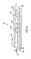
- FIG. 5 is an enlarged view that depicts the orientation of the apparatus in FIG. 1 for performing a sphincterotomy;
- FIG. 6 depicts the apparatus of FIG. 1 positioned through a duodenoscope for dislodging material within the common bile duct;
- FIG. 7 is a cross-section of an alternative embodiment of the apparatus as viewed generally along lines 7-7 in FIG. 2.;
- FIG. 8 is a cross-section of still another embodiment of the apparatus taken along lines 7-7 in FIG. 2;
- FIG. 9 is a partial cross-section of the invention highlighting the positioning device;
- FIG. 10 is a cutaway view of an alternative embodiment of the present invention used to support the extension of the needle knife;
- FIGS. 11A and 11B are enlarged views of the a pivot element and a stabilizing element from FIG. 10; and
- FIG. 12 is a plan view of an alternate embodiment of the present invention which combines a positioning device and a support for the needle knife.
- FIG. 1 depicts
catheter apparatus 100 that has the capability of injecting a contrast agent into the biliary tree, accurately positioning a cutting wire, of performing a sphincterotomy and of dislodging a gallstone into the duodenum.Apparatus 100 includes acatheter 101 which, for purposes of definition, includesproximal portion 102 extending fromproximal end 103 anddistal end 104 withdistal portion 105 extending a short distance fromdistal end 104. In a typical application, the catheter will have a working length of 200 cm anddistal portion 105 will have a length of 6 cm to 9 cm. Normallydistal portion 105 will have a diameter that is smaller than the diameter ofproximal portion 102 to increase the flexibility ofdistal portion 105. The reduction in diameter also makesdistal end 104 less traumatic and allowsdistal portion 105 to reach smaller passages while allowing the largerproximal portion 102 to provide necessary hoop strength and rigidity, particularly whereproximal portion 102 is coextensive with the working channel of a duodenoscope. For example, the proximal and distal portions might have diameters corresponding to 7 Fr and 5.5 Fr catheter sizes (i.e., 0.09″ and 0.07″ respectively). - As shown particularly in FIG. 2,
catheter 101 has three lumens.First lumen 201 has a diameter that is greater than eithersecond lumen 202 orthird lumen 203. In one particular embodimentfirst lumen 201 is square shaped with each side approximately 0.040″ inproximal portion 102 that reduces to about 0.037″ indistal portion 105 to receive a standard 0.035″ guidewire. In additionfirst lumen 201 may be, and as shown in FIG. 2, is offset from the center of thecatheter 101. - The cross section of both
second lumen 202 andthird lumen 203 are each smaller than the cross section offirst lumen 201 and are radially offset from the centerline ofcatheter 101, from each other and fromfirst lumen 201. In one particular embodiment the cross section ofthird lumen 203 has a diameter of 0.028″ inproximal portion 102 that reduces to about 0.020″ indistal portion 105 andsecond lumen 202 has an internal diameter of 0.028″ inproximal portion 102 that reduces to about 0.020″ indistal portion 105. As described later, thisthird lumen 203 carries a cutting wire for performing a sphincterotomy and for allowing the infusion of a contrast agent at reasonable rates. The cutting wire can also be positioned, as described later, as desired. While the description contained herein describes thefirst lumen 201 having a square cross section shape, it would be apparent to one of ordinary skill in the art that the invention may be practiced in any of the lumens by changing the cross section of the lumen to a shape other than a circle. The angular spacing betweensecond lumen 202 andthird lumen 203 is about 45 degrees and the angular spacing betweenfirst lumen 201 and each oflumens proximal portion 102 readily passes through the working channel of any duodenoscope. These angular relationships have been used in the past to position the device. While the invention may be used with these angular relationships, the invention itself allows the device to be positioned which reduces the necessity of strict adherence to the previously used angular relationships. - Referring again to FIGS. 1 and 2, each of
lumens proximal portion 102 and an exit port indistal portion 105. Generally, and as described in more detail later,first lumen 201 has an exit port throughdistal end 104 while the exit ports forlumens distal portion 105 depending upon a particular application. - In FIG. 1, the entry ports in
proximal portion 102 adjacentproximal end 103 include anentry port 106 that provides access tofirst lumen 201 and includes an optional Leur lock fitting 107. Proximally positionedentry port 108 provides access tosecond lumen 202 and includes optional Leur lock fitting 109.Proximal entry port 110 forthird lumen 203 is located coextensively with a portion ofhandle 111 attached toproximal end 103. One of ordinary skill in the art would understand that this specific configuration is given as an example and not meant to limit the invention. Various other configurations would be apparent to one of ordinary skill in the art to practice the invention described herein. - Referring to the
distal portion 105,catheter 101 in this particular embodiment carriesexpansible balloon 112 proximally of the excursion of cuttingwire 113 externally ofcatheter 101. As described in U.S. patent application Ser. No. 09/154,834 in the name of Rowland, et al., and owned by the owner of the present application and already incorporated herein by reference in its entirety,second lumen 202 emerges at a distal exit port through the side ofcatheter 101 with the interior ofexpansible balloon 112. An extension ofsecond lumen 202 beyond the distal port is sealed by known methods of manufacture. Consequently, fluid forced throughentrance port 108, as by a syringe (not shown) attached to Leur lock fitting 109, expandsballoon 112 into an occluding orientation with an inflated diameter in the range up to 20 mm. -
First lumen 201 extends throughcatheter 101 and terminates with an exit port indistal end 104. Thusfirst lumen 201 is adapted for receiving a guidewire through theentry port 106 that will extend throughcatheter 101 and exitdistal end 104 and allow the catheter to slide over that guidewire. - Referring to FIG. 3,
distal end 301 of cuttingwire 113 attaches to aclamp 302 formed at the distal end ofthird lumen 203. Spaced skivedports active portion 305 of thecutting wire 113 to emerge fromcatheter 101 through skivedaperture 303, parallel thecatheter 101 exteriorly thereof and return intothird lumen 203 throughport 304 and reinforcingsleeve 306. Cuttingwire 113 then extends throughthird lumen 203 to handle 111 shown in FIG. 1 where it emerges asproximal end portion 114. -
Handle 111, as shown in FIG. 1, includescentral member 115 terminating withthumb ring 116. Thecentral member 115 extends through and slides with respect tobody section 117 having opposed finger rings 118. Thecentral member 115 also attaches tocatheter 101, and is therefore an extension ofcatheter 101.Member 117 additionally includesinternal connector 119 for clampingproximal end 114 of cuttingwire 113. Thus, whenbody 117 is at its distal position as shown in FIG. 1,distal portion 105 ofcatheter 101 is in essentially straight line as shown in FIG. 1 withactive portion 305 of cuttingwire 113 being closelyadjacent catheter 101. Retractingbody portion 117,causes cutting wire 113 to benddistal end 104 upwardly as shown in FIG. 3 to a position that is essentially at right angles to the main axis of the catheter, as will be shown later. -
Connector block 119 andcutting wire 113 are generally conductive members that attach throughRF connector 120 toRF heating source 121. The use of suchRF heating sources 121 for energizingcutting wire 113 thereby to cut the sphincter muscle is well known in the art and represents one possible sphincterotomy procedure that can be adapted for the apparatus of this invention and is not described further. - With this description of the apparatus structure, it will now be possible to understand its use in a particular application. FIG. 4 discloses, in a partially broken and schematic view, the positioning of
duodenoscope 401 induodenum 402 adjacent sphincter ofOddi 403.Catheter 101 such as constructed in FIG. 1 passes through sphincter ofOddi 403 into thecommon bile duct 404, bypassingpancreatic duct 405.Distal end 104 does not extend togallbladder 406. - Fluoroscopy allows the appropriate positioning by utilizing a series of radio-
opaque markers 406 atdistal portion 105 that may includeclamp 302 and reinforcingsleeve 306 in FIG. 3.Catheter 101 can be positioned with or without the presence ofguidewire 408 infirst lumen 201 shown in FIGS. 2, and 3. For purposes of injecting the contrast agent, anyguidewire 408 can be withdrawn to allow the contrast agent to be injected throughfirst lumen 201 for purposes of fluoroscopic examination to confirm the presence of one ormore gallstones 409. It is also possible during the operation to expandballoon 112 to occludecommon bile duct 404 and block any migration of contrast agent intoduodenum 402 orpancreatic duct 405. - FIG. 5 is an enlarged
view showing duodenum 402, sphincter ofOddi 403, portions ofpancreatic duct 405 andcommon bile duct 404. In FIG. 5catheter 101 has been positioned relative to theduodenoscope 401 through the opening of sphincter ofOddi 403. Thehandle 111 in FIG. 1 has been drawn proximally to deflectdistal portion 105 into essentially a right angle configuration such thatcutting wire 113 abuts a portion of sphincter ofOddi 403. The application of RF heating tocutting wire 113 then will cut sphincter ofOddi 403 and enlarge the opening therethrough. As will be apparent, the sphincterotomy is performed with direct visualization of the sphincter of Oddi through the duodenoscope. - Moreover, as has been observed by others, catheters having guidewire and cutting wire lumens tend to assume a particular angular orientation when
distal portion 105 emerges from the duodenoscope. This orientation is essentially independent of the angular position of the catheter when it is inserted into the duodenoscope. The offset nature oflumen 203 as shown in FIG. 2, improves the location of cuttingwire 113 asdistal portion 105 passes through sphincter ofOddi 403. Specifically the angularly offset brings cuttingwire 113 into better alignment withcommon bile duct 404 and displaces the cutting wire frompancreatic duct 405. - FIG. 6 depicts the catheter after the sphincterotomy and after
catheter 101 is advanced overguidewire 408, if used. FIG. 6 also disclosescatheter 101 afterballoon 112 has been moved beyondgallstone 409 inbile duct 404.Balloon 112 is expanded so that upon withdrawal ofcatheter 101balloon 112 will dislodgegallstones 409 and sweep them through sphincter ofOddi 403 intoduodenum 402. - As will now be apparent from the description of the
particular catheter apparatus 100 shown in FIG. 1 and its use as discussed with respect to FIGS. 4, 5, and 6, the single catheter apparatus is capable of providing diagnostic contrast agent injection, of performing a sphincterotomy and of dislodging gallstones in the common bile duct or other portions of the biliary tree without having to exchange a catheter. Moreover, positioning and sizing of the lumens enables these functions to be performed with a catheter apparatus that is readily adapted for use in the working channels of standard duodenoscopes. Consequently the gallstones can be removed from the biliary tree without bile duct incisions and accompanying surgical procedures, as duodenoscope can be introduced through the alimentary tract. Consequently the entire procedure is adapted for being performed more rapidly than prior art procedures and with fewer components. The net effect is to reduce patient trauma and the overall time and cost of conducting the procedure. - In FIG. 1
balloon 112 is located proximally of cuttingwire 113. FIG. 7 discloses an alternative embodiment in whichballoon 701 is located distally of cuttingwire 113. More specifically, the distal end oflumen 202A, corresponding tosecond lumen 202 in FIG. 3 is sealed. Side facingexit port 702 skived or otherwise formed incatheter 101 opens intochamber 703 formed byballoon 701. First sealingportion 704 and a sealingportion 705 ofballoon 701 connect proximally and distally ofaperture 702 respectively andseal chamber 703. - Introduction of a balloon inflation fluid through
lumen 202A expandsballoon 701 into an occluding orientation corresponding to the orientation ofballoon 701. Retraction ofcatheter 101 withdistal balloon 701 inflated enables withdrawal of a gallstone from the bile duct. This particular embodiment is particularly adapted when it is determined that a gallstone is located high in the biliary tree to minimize the incursion ofdistal portion 105 through the biliary tree beyond the gallstone or in any application in which the internist desires to minimize the length ofdistal portion 105 that extends beyond the occluding balloon. - FIG. 8 discloses another embodiment for enlarging the sphincter of Oddi and performing another procedure, such as injecting a contrast agent into the biliary tree, as might be used in the diagnosis and treatment of a stricture in the biliary tree. In this particular
embodiment exit port 801 fromsecond lumen 202B is located indistal end 104 ofdistal portion 105.First lumen 201 then can be used for a guidewire andlumen 202B, for injecting the contrast agent directly into the biliary tree while the guidewire remains in place. The apparatus would then be positioned to perform a sphincterotomy without having to exchange a catheter should the procedure be warranted. - As still another alternative, the internist could utilize a conventional catheter for purposes of injecting the contrast agent to determine the need for gallstone removal. If treatment were indicated, the internist could then utilize apparatus as shown in FIG. 1 with a single exchange over the guidewire that would pass through
lumen 201 as previously described. - As can be seen from the above description one of the steps in the treatment of obstructive disease is normally the practice of tissue incision which is achieved by advancing a cutting wire endoscopically to the target site. As explained above, once the catheter tip is in position, the catheter tip is bowed (FIG. 5) to expose
cutting wire 113 to tissue. Diathermic current is passed throughcutting wire 113 from RF Heating Source 121 (FIG. 1) which allows the endoscopist to incise and cauterize the tissue at the target site. Safe and effective results are only obtained through precision positioning ofcutting wire 113. - FIG. 9 depicts a section of a
positioning device 900 residing withinlumen 201 of amulti-lumen catheter 101. As shown in FIG. 2lumen 201 has an internal shape, in this case a square, which allows thepositioning device 900 to transfer torque todistal end 104. The internal shape oflumen 201 in FIG. 2 is depicted to be a square, but one of ordinary skill in the art would understand that any internal shape which allows the torque transfer may be used and is within the disclosed invention. Referring back to FIG. 9,positioning device 900 consists ofcable assembly 901, which is substantially encircled bytorque transmission element 902 andcog 903.Proximate end 904 of positioning device is attached to handle 111 (not shown) whiledistal end 905 ofpositioning device 900 is located in the distal portion 105 (not shown). While FIG. 9 illustrates atorque transmission element 902 which completely encirclescable assembly 901, it would be apparent to one of ordinary skill in the art thattorque transmission element 902 need not entirely encirclecable assembly 901 and any configuration betweentorque transmission element 902 andcable assembly 901 which allows the translation of reciprocal movement to rotational motion is within the scope of the invention. Thecog 903 can also be referred to as a sliding member. -
Cable assembly 901 is connected at its proximal end (not shown) to the distal end ofhandle 111, traverses throughlumen 203 andtorque transmission element 902 with the distal end ofcable assembly 901 fixed tocog 903. Reciprocal motion of thehandle 111 attached to thecable assembly 901 introduces reciprocal motion in the proximal portion of thecable assembly 901 between thehandle 111 andtorque transmission element 902. Theouter circumference 906 of thecable assembly 901 includes a helical or advancing spiral thread. - The
torque transmission element 902 is located and fixed within lumen 201 a short distance from distal end 104 (FIG. 1) and proximal tocog 903. The internal portion oftorque transmission element 902, or the portion which comes into contact with thecable assembly 901, contains a helical or advancing spiral thread which interacts and mates with the helical or advancing spiral thread ofcable assembly 901. The external portion oftorque transmission element 902, or the portion which comes into contact withlumen 201, is shaped to interact with and mate with the interior surface oflumen 201 and is fixed toinner lumen 201. The purpose oftorque transmission element 902 is to change the reciprocal cable movement received from the reciprocal movement of the attachedhandle 111 to rotational cable movement indirection 907. Thetorque transmission element 902 may be molded as part of or attached tolumen 201. - The
cog 903 is located betweentorque transmission element 902 anddistal end 104 and at a distance from each so as to aid in creating effective rotation of the catheterdistal end 104. This rotation, in the direction of 907, is the result of thetorque transmission element 902 translation of the reciprocal movement received fromhandle 111 into rotational cable movement. Astorque transmission element 902 receives reciprocal movement fromcable assembly 901,torque transmission element 902 cannot moved because it is fixed to lumen 201 and the internal helical or advancing spiral inside oftorque transmission element 902 imparts a rotational affect oncable assembly 901 in a similar manner to the spin a bullet receives from the rifling inside of a rifle's barrel.Cog 903 is not fixed to lumen 201 and is capable of reciprocal movement withinlumen 201 as thecable assembly 901 advances and retracts. The purpose ofcog 903 is to transfer the torque received from cable attached totorque transmission element 902 to the distal segment of the catheter and this is achieved whencog 903 is fixed tocable assembly 901. While the invention is shown withcog 903, one of ordinary skill in the art would understand that thecog 903 is not absolutely necessary to the invention, but instead aids in the transmission of the torque created bytorque transmission element 902.Cog 903, while included in the preferred embodiment, may be eliminated and thedistal tip 104 would still be capable of being positioned. The resistance between thetorque transmission element 902 and thecable assembly 901 may be varied to adjust the proportion of the reciprocal movement which is translated into rotational motion.Cog 903 may also be shaped to increase the efficiency of the transfer of rotational movement from the distal end of the cable to the distal segment of the catheter. For example, where the cross-section oflumen 201 is in the shape of a square the cross section ofcog 903 would also be a square. - In operation
distal end 104 of the cutting device is advanced through thelumen 203 of the endoscope to the target area. Cuttingwire 113 is retracted to bow the tip exposing the cutting wire (FIG. 5). The distal end ofdevice 900 is advanced throughlumen 201 untiltorque transmission element 902 is in, or near thedistal portion 105. Thehandle 111, which is connected tocable 901, is reciprocated, causing theproximal end 904 ofcable assembly 901 to be reciprocated. When the proximal end ofcable assembly 901 is reciprocated,torque transmission element 902 translates this movement into rotation which is transferred fromcog 903 to the catheterdistal end 104. As catheterdistal end 104 is rotated so is cuttingwire 113 which resides inlumen 203. After the incision is made in the target area, cuttingwire 113 is advanced relieving the bow. The catheter assembly can then be removed from the body. Overall, the effect of thepositioning system 900 is to translate the reciprocal movement in thehandle 111 into rotational movement at thedistal end 104 of the catheter. - FIG. 10 depicts a
multi-lumen catheter 1000 which includes an alternate embodiment of the present invention for the precise positioning of a needle knife. Withincatheter 101 ofmulti-lumen catheter 1000 is lumen 1001 which is used forneedle knife 1002. Withinlumen 1001 residesneedle knife wire 1003.Needle knife wire 1003 is attached at the proximal end to a sliding mechanism ofhandle 1004 and on the distal end toneedle knife 1002.Needle knife 1002 is capable of extending beyonddistal end 104 ofcatheter 101.Circumference 1005 ofneedle knife wire 1003 includes helical or advancingspiral 1006. FIG. 10 shows helical or advancingspiral 1006 along the entire length ofneedle knife wire 1003, but helical or advancing spiral 1006 portion ofneedle knife wire 1003 need not be included along the entire length and may be limited to inclusion over a short distance ofneedle knife wire 1003 close to thedistal end 104. Helical or advancingspiral 1006 is required wherepivot element 1007 and stabilizingelement 1008 attach and alongneedle knife wire 1003 wherepivot element 1007 and stabilizingelement 1008 may travel. In one embodiment the helical or advancing spiral 1006 may be located between 6 and 10 cm from the distal end. -
Pivot element 1007 and stabilizingelement 1008 are attached toneedle knife wire 1003.Pivot element 1007 is located proximal to stabilizingelement 1008 and is used to prevent torsion build up. While the preferred embodiment includespivot element 1007, the invention can be practiced without the inclusion ofpivot element 1007. Stabilizingelement 1008 is located a short distance fromdistal end 104 and may be molded as part of the lumen or attached to the lumen. In one embodiment the stabilizingelement 1008 was located 6 to 10 cm from the distal tip. The purpose of the stabilizing element is to preventneedle knife 1002 from being pushed back intolumen 1001 when pressure is applied to theneedle knife 1002, for example when an incision is made. The stabilizingelement 1008 is part of or fixed to the lumen wall and uses this attachment to prevent theneedle knife 1002 from being pushed back into the lumen. Stabilizingelement 1008 may have a helical or advancing spiral 1109 (FIG. 11B) along its inner circumference which mates with the helical or advancingspiral 1006 ofneedle knife wire 1003. - When the sliding mechanism of
handle 1004 which is attached toneedle knife wire 1003 reciprocates,needle knife wire 1003 also reciprocates. Asneedle knife wire 1003 reciprocates, threadedneedle knife wire 1003 rotates through stabilizingelement 1008 andneedle knife 1002 advances out of or retracts intolumen 1001. The sliding mechanism ofhandle 1004 can be locked whenneedle knife 1002 is deployed to its desired length. As pressure is applied toneedle knife 1002 during incision any forward or backward movement ofneedle knife 1002 is negated by stabilizingelement 1008 which acts, to resist movement of the needle knife back into thelumen 1001. This resistance is created by the interaction of the matched helical windings of the stabilizingelement 1008 and theneedle knife wire 1003. Stabilizingelement 1008 allowsneedle knife 1002 to be locked regardless of the overall catheter length. - In operation
distal end 104 ofdevice 100 is advanced through the endoscope to the target area.Needle knife wire 1003 is advanced via the sliding mechanism ofhandle 1004 to exposeneedle knife 1002 to the desired length. The sliding mechanism ofhandle 1004 is then locked into position. As pressure is applied toneedle knife 1002 during the incision, stabilizingelement 1008 ensures the integrity of the depth of cut ofneedle knife 1002. Once the incision is made in the target area,needle knife 1002 is retracted and the catheter assembly is removed from the body. - FIGS. 11A and 11B show a blown up diagram of the
pivot element 1007 and thestabilization elements 1008 respectively. The pivot element shown in FIG. 11A, consists of three parts, aproximal element 1101, adistal element 1102 and anenclosure element 1103. When theneedle knife wire 1003 is pushed towards thedistal end 104,proximate element 1101 makes contact withdistal element 1102 and ensures the entire needle knife wire progresses within the lumen toward thedistal end 104. When theneedle knife wire 1003 is retracted,proximal element 1101 contacts theproximal portion 1104 of theenclosure element 1103 and thedistal portion 1105 of theenclosure element 1103 contacts thedistal element 1102 and ensures the entire needle knife wire is retracted. Within thepivot element 1007 is aspace 1106 between theproximal element 1101 and thedistal element 1102 and the sides of theenclosure element 1103. There is also aspace 1107 between theneedle knife wire 1003 and theentrance 1107 andexit 1108 of theenclosure element 1103. The stabilizingelement 1008 is shown in FIG. 11B which highlights themating 1104 between the helical windings on theneedle knife wire 1003 and the stabilizingelement 1008. - FIG. 12 is a perspective view of a device which incorporates both a stable needle knife to maintain the blade depth and which allows the user to position the blade in a desired direction. Within
catheter 101 ofmulti-lumen catheter 1200 is lumen 1001 which is used forneedle knife 1002. Withinlumen 1001 residesneedle knife wire 1003.Needle knife wire 1003 is attached at the proximal end to a sliding mechanism ofhandle 1004 and on the distal end toneedle knife 1002.Needle knife 1002 is capable of extending beyonddistal end 104 ofcatheter 101. Thecircumference 1005 ofneedle knife wire 1003 includes helical or advancingspiral 1006. In one embodiment the helical or advancingspiral element 1008 is also included in thedevice 1200 to prevent theblade 1002 from being pushed back into the lumen when pressure is applied to theneedle knife blade 1002. The mechanism of FIG. 12 which prevents the blade of theneedle knife 1002 from being pushed back into the lumen has been described with respect to FIG. 10. The needle knife (stabilizing) threaded element may be molded as part of or attached to the lumen. A pivot element 1007 (FIG. 10) may be attached to theneedle knife wire 1003 if desired. - FIG. 12 also includes a mechanism for steering the position of the
cutting wire 113.Steering wire 1201 is connected at its proximal end to the distal end ofhandle 1202, traverses throughlumen 1203 and steering wire threadedelement 1204. The internal surface of steering wire threadedelement 1204 matches and mates with the external circumference ofsteering wire 1201. As thesteering wire 1201 is reciprocated via a sliding mechanism onhandle 1202, the threadedsteering wire 1201 rotates through the steering wire threadedelement 1204. This rotation causes the distal section of the catheter to rotate. The sliding mechanism can be locked when the desired position is achieved. In one embodiment the distal end of thesteering wire 1201 was threaded for 10 cm at a distance of 8 cm from the distal tip. The major advantage ofdevice 1200 is the ability to rotate the distal tip either clockwise or counterclockwise as the sliding mechanism is reciprocated and to ensure the blade of the needle knife does not retract into the lumen when used. The steering wire threaded element may be molded as part of or attached to the lumen. A cog 903 (FIG. 9) may also be included for a more effective transfer of rotational position to thedistal end 104. - FIG. 12 also shows a
bowing wire 1205 included indevice 1200. The inclusion of thebowing wire 1205 allows the distal tip of the catheter to be turned up to 90 degrees from the longitudinal axis of thecatheter body 101. - In operation the distal tip of the device is advanced through
lumen 1001 of the endoscope to the target area. Once the distal tip reaches the target area, the tip of the catheter is bowed to the desired angle. The steering device is then advanced throughlumen 1203 until the steering element is in, or near, thedistal portion 105. The tip of the catheter is than rotated to the desired position and locked when the desired position is obtained. The needle knife is than advanced to expose the needle knife to the desired length. Once the exposed length is attained, the handle is locked to ensure the needle knife blade is not pushed back into the lumen when pressure is applied to it. The incision is then made in the target area and the needle knife is retracted, the bow is released and the catheter assembly is removed from the body. - Therefore, it will now be apparent that apparatus constructed in accordance with this invention attains the several objects and the advantages of this invention. More particularly, catheter apparatus constructed in accordance with this invention allows the injection of a contrast agent, the performance of a sphincterotomy and dislodging gallstones from the common bile duct through the enlarged sphincter of Oddi into the duodenum all without requiring any catheter exchanges. Moreover, this apparatus allows such a procedure to occur through a duodenoscope to minimize patient trauma. The use of a single catheter with an elimination of catheter exchanges further reduces the time and costs associated with the use of multiple, single-function catheter devices.
- As will be apparent from the foregoing description, many alterations can be made to the specifically disclosed embodiments. Different balloon structures can be used and located at alternative positions. Different cutting wire embodiments and orientations can be used. Thus, although this invention has been disclosed in terms of certain embodiments, it will be apparent that many modifications can be made to the disclosed apparatus without departing from the invention. In particular, it is considered that all of the foregoing embodiments may be used in conjunction with a handle fixed to the cutting wire but rotatable relative to the catheter. Therefore, it is the intent of the appended claims to cover all such variations and modifications as come within the true spirit and scope of this invention.
Claims (62)
1. In an endoscopic catheter having a distally located tissue cutting device in a first lumen thereof, the improvement for orienting the cutting device which comprises:
providing said catheter with a second lumen having a reciprocating cable therein, said second lumen having a fixed member therein for imparting rotary motion to said cable when reciprocated therethrough; and
reciprocation of said cable causing rotation of at least a distal portion of said catheter to orient said cutting device.
2. Catheter of claim 1 wherein said cable has spiral threads on an outer circumference thereof.
3. Catheter of claim 2 wherein said fixed member includes a spiral thread on an inner circumference thereof.
4. Catheter of claim 1 wherein said cutting device is a sphincterotome.
5. Catheter of claim 1 wherein said cutting device is a papillotome.
6. Catheter of claim 1 wherein said cutting device operates in response to energy from an rf heating source.
7. Catheter of claim 1 wherein said distal portion of said catheter is curved and the cutting device is a needle knife.
8. In an endoscopic catheter having a distally located tissue cutting device in a first lumen thereof, the improvement for orienting the cutting device which comprises:
providing said catheter with a second lumen having a reciprocating cable therein, said second lumen having fixed member therein for imparting rotary motion to said cable when reciprocated therethrough;
said cable having a sliding member attached thereto distally of said fixed member; and
reciprocation of said cable causing rotation of said sliding member and at least a distal portion of said catheter to orient said cutting device.
9. Catheter of claim 8 wherein said second lumen is non-round in cross section.
10. Catheter of claim 8 wherein said second lumen is square in cross section.
11. Catheter of claim 10 where said sliding member is square in cross section.
12. Catheter of claim 8 wherein said cable has spiral threads on an outer circumference thereof.
13. Catheter of claim 12 wherein said fixed member includes a spiral thread on an inner circumference thereof.
14. Catheter of claim 8 wherein the distal portion of said catheter is curved and the cutting device is a needle knife.
15. Catheter of claim 8 wherein said cutting device is a sphincterotome.
16. Catheter of claim 8 wherein said cutting device is a papillotome.
17. Method for orientating a tissue cutting device located in a distal portion of a first lumen of an endoscopic catheter which comprises:
providing said catheter with a second lumen having a reciprocating cable therein, said second lumen having a fixed member therein for imparting rotary motion to said cable when reciprocated therethrough; and
reciprocating said cable to cause rotation of at least a distal portion of said catheter thereby orienting said cutting device.
18. Method of claim 17 wherein said cable has spiral threads on an outer circumference thereof.
19. The device of claim 18 wherein said fixed member includes a spiral thread on an inner circumference thereof.
20. Method of claim 17 wherein said cutting device is a sphincterotome.
21. Method of claim 17 wherein said cutting device is a papillotome.
22. Method of claim 17 wherein said cutting device operates in response to energy from an rf heating source.
23. Method of claim 17 wherein the distal portion of said catheter is curved and the cutting device is a needle knife.
24. Method for orientating a tissue cutting device located in a distal portion of a first lumen of an endoscopic catheter which comprises:
providing said catheter with a second lumen having a reciprocating cable therein, said second lumen having a fixed member therein for imparting rotary motion to said cable when reciprocated therethrough and a sliding member attached to said cable distally of said fixed member; and
reciprocating said cable to cause rotation of said sliding member and at least a distal portion of said catheter to orient said cutting device.
25. Method of claim 24 wherein said second lumen is non-round in cross section.
26. Method of claim 25 wherein said second lumen is square in cross section.
27. Method of claim 25 wherein said sliding member is square in cross section.
28. Method of claim 24 wherein said cable has spiral threads on an outer circumference thereof.
29. Method of claim 28 wherein said fixed member includes a spiral thread on an inner circumference thereof.
30. Method of claim 24 wherein said distal portion of said catheter is curved and the cutting device is a needle knife.
31. In an endoscopic catheter having a cable actuated needle knife in a lumen thereof, said needle knife being deployable from a distal end of said catheter, the improvement for substantially preventing movement of said needle knife after deployment which comprises a distally positioned fixed stabilizing element in said lumen internally engaging said needle knife cable to prevent such movement.
32. Catheter of claim 31 wherein said needle knife cable includes a spiral thread on an outer circumference thereof.
33. Catheter of claim 32 wherein said fixed stabilizing element includes a spiral thread on an inner circumference thereof.
34. Catheter of claim 33 further comprising a pivot element included within said needle knife cable.
35. Catheter of claim 34 wherein said pivot element is proximal of said fixed stabilizing element.
36. Catheter of claim 35 wherein said needle knife cable includes a spiral thread on an outer circumference thereof.
37. Catheter of claim 36 wherein said fixed stabilizing element includes a spiral thread on an inner circumference thereof.
38. In an endoscopic catheter having a cable actuated needle knife in a first lumen thereof, said needle knife being deployable from a distal end of said catheter, the improvement for orienting the cutting device and for substantially preventing movement of said needle knife after deployment which comprises:
providing said catheter with a second lumen having a reciprocating cable therein, said second lumen having a fixed member therein for imparting rotary motion to said cable when reciprocated therethrough;
reciprocation of said cable causing rotation of at least a distal portion of said catheter to orient said cutting device, and
providing a distally positioned fixed stabilizing element in said first lumen internally engaging said needle knife cable to prevent such movement.
39. Catheter of claim 38 wherein said reciprocating cable has spiral threads on an outer circumference thereof.
40. Catheter of claim 39 wherein said fixed member includes a spiral thread on an inner circumference thereof.
41. Catheter of claim 38 wherein said needle knife operates in response to energy from an rf heating source.
42. Catheter of claim 38 wherein said distal portion of said catheter is curved.
43. Catheter of claim 38 wherein said needle knife cable includes a spiral thread on an outer circumference thereof.
44. Catheter of claim 43 wherein said fixed stabilizing element includes a spiral thread on an inner circumference thereof.
45. Catheter of claim 38 further comprising a pivot element included within said needle knife cable.
46. Catheter of claim 45 wherein said pivot element is proximal of said stabilizing element.
47. Catheter of claim 46 wherein said needle knife cable includes a spiral thread on an outer circumference thereof.
48. Catheter of claim 47 wherein said fixed stabilizing element includes a spiral thread on an inner circumference thereof.
49. In an endoscopic catheter having a cable actuated needle knife in a first lumen thereof, said needle knife being deployable from a distal end of said catheter, the improvement for orienting the cutting device and for substantially preventing movement of said needle knife after deployment which comprises:
providing said catheter with a second lumen having a reciprocating cable therein, said second lumen having a fixed member therein for imparting rotary motion to said cable when reciprocated therethrough;
said cable having a sliding member attached thereto distally of said fixed member;
reciprocation of said cable causing rotation of said sliding member and at least a distal portion of said catheter to orient said cutting device, and
providing a distally positioned fixed stabilizing element in said first lumen internally engaging said needle knife cable to prevent such movement.
50. Catheter of claim 49 wherein said second lumen is non-round in cross section.
51. Catheter of claim 50 wherein said second lumen is square in cross section.
52. Catheter of claim 51 wherein said sliding member is square in cross section.
53. Catheter of claim 49 wherein said cable has spiral threads on an outer circumference thereof.
54. Catheter of claim 53 wherein said fixed member includes a spiral thread on an inner circumference thereof.
55. Catheter of claim 49 wherein said needle knife operates in response to energy from an rf heating source.
56. Catheter of claim 49 wherein said distal portion of said needle knife is curved.
57. Catheter of claim 49 wherein said needle knife cable includes a spiral thread on an outer circumference thereof.
58. Catheter of claim 57 wherein said fixed stabilizing element includes a spiral thread on an inner circumference thereof.
59. Catheter of claim 49 further comprising a pivot element included within said needle knife cable.
60. Catheter of claim 59 wherein said pivot element is proximal of said fixed stabilizing element.
61. Catheter of claim 60 wherein said needle knife cable includes a spiral thread on an outer circumference thereof.
62. Catheter of claim 61 wherein said fixed stabilizing element includes a spiral thread on an inner circumference thereof.
Priority Applications (2)
| Application Number | Priority Date | Filing Date | Title |
|---|---|---|---|
| US10/436,074 US7118584B2 (en) | 2001-01-18 | 2003-05-13 | Steerable sphincterotome and methods for cannulation, papillotomy and sphincterotomy |
| US11/525,826 US7947056B2 (en) | 2001-01-18 | 2006-09-25 | Steerable sphincterotome and methods for cannulation, papillotomy and sphincterotomy |
Applications Claiming Priority (2)
| Application Number | Priority Date | Filing Date | Title |
|---|---|---|---|
| US09/761,843 US6579300B2 (en) | 2001-01-18 | 2001-01-18 | Steerable sphincterotome and methods for cannulation, papillotomy and sphincterotomy |
| US10/436,074 US7118584B2 (en) | 2001-01-18 | 2003-05-13 | Steerable sphincterotome and methods for cannulation, papillotomy and sphincterotomy |
Related Parent Applications (1)
| Application Number | Title | Priority Date | Filing Date |
|---|---|---|---|
| US09/761,843 Continuation US6579300B2 (en) | 2001-01-18 | 2001-01-18 | Steerable sphincterotome and methods for cannulation, papillotomy and sphincterotomy |
Related Child Applications (1)
| Application Number | Title | Priority Date | Filing Date |
|---|---|---|---|
| US11/525,826 Continuation US7947056B2 (en) | 2001-01-18 | 2006-09-25 | Steerable sphincterotome and methods for cannulation, papillotomy and sphincterotomy |
Publications (2)
| Publication Number | Publication Date |
|---|---|
| US20030191486A1 true US20030191486A1 (en) | 2003-10-09 |
| US7118584B2 US7118584B2 (en) | 2006-10-10 |
Family
ID=25063397
Family Applications (3)
| Application Number | Title | Priority Date | Filing Date |
|---|---|---|---|
| US09/761,843 Expired - Lifetime US6579300B2 (en) | 2001-01-18 | 2001-01-18 | Steerable sphincterotome and methods for cannulation, papillotomy and sphincterotomy |
| US10/436,074 Expired - Fee Related US7118584B2 (en) | 2001-01-18 | 2003-05-13 | Steerable sphincterotome and methods for cannulation, papillotomy and sphincterotomy |
| US11/525,826 Expired - Fee Related US7947056B2 (en) | 2001-01-18 | 2006-09-25 | Steerable sphincterotome and methods for cannulation, papillotomy and sphincterotomy |
Family Applications Before (1)
| Application Number | Title | Priority Date | Filing Date |
|---|---|---|---|
| US09/761,843 Expired - Lifetime US6579300B2 (en) | 2001-01-18 | 2001-01-18 | Steerable sphincterotome and methods for cannulation, papillotomy and sphincterotomy |
Family Applications After (1)
| Application Number | Title | Priority Date | Filing Date |
|---|---|---|---|
| US11/525,826 Expired - Fee Related US7947056B2 (en) | 2001-01-18 | 2006-09-25 | Steerable sphincterotome and methods for cannulation, papillotomy and sphincterotomy |
Country Status (8)
| Country | Link |
|---|---|
| US (3) | US6579300B2 (en) |
| EP (1) | EP1351617B1 (en) |
| JP (1) | JP4366077B2 (en) |
| AT (1) | ATE363238T1 (en) |
| AU (1) | AU2002235394B2 (en) |
| CA (1) | CA2433406A1 (en) |
| DE (1) | DE60220376T2 (en) |
| WO (1) | WO2002056784A2 (en) |
Cited By (1)
| Publication number | Priority date | Publication date | Assignee | Title |
|---|---|---|---|---|
| US20070265497A1 (en) * | 2006-05-03 | 2007-11-15 | Wilson-Cook Medical Inc. | Endoscope rotational and positioning apparatus and method |
Families Citing this family (105)
| Publication number | Priority date | Publication date | Assignee | Title |
|---|---|---|---|---|
| US6579300B2 (en) | 2001-01-18 | 2003-06-17 | Scimed Life Systems, Inc. | Steerable sphincterotome and methods for cannulation, papillotomy and sphincterotomy |
| US7153320B2 (en) * | 2001-12-13 | 2006-12-26 | Scimed Life Systems, Inc. | Hydraulic controlled retractable tip filter retrieval catheter |
| US6852110B2 (en) * | 2002-08-01 | 2005-02-08 | Solarant Medical, Inc. | Needle deployment for temperature sensing from an electrode |
| WO2004082486A1 (en) * | 2003-03-18 | 2004-09-30 | Anke Gasche | Apparatus and method for colonoscopic appendectomy |
| US7771463B2 (en) | 2003-03-26 | 2010-08-10 | Ton Dai T | Twist-down implant delivery technologies |
| US20040193179A1 (en) * | 2003-03-26 | 2004-09-30 | Cardiomind, Inc. | Balloon catheter lumen based stent delivery systems |
| JP2006521161A (en) * | 2003-03-26 | 2006-09-21 | カーディオマインド インコーポレイティッド | Implant delivery technology |
| US7651521B2 (en) | 2004-03-02 | 2010-01-26 | Cardiomind, Inc. | Corewire actuated delivery system with fixed distal stent-carrying extension |
| US7744585B2 (en) | 2004-09-29 | 2010-06-29 | Boston Scientific Scimed, Inc. | Catheter with directed flow design |
| US7824376B2 (en) * | 2004-12-24 | 2010-11-02 | Olympus Corporation | Injection needle apparatus for making injection in tissue in body cavity |
| BRPI0406012A (en) * | 2004-12-31 | 2006-08-22 | Everson Luiz De Almeid Artifon | constructive disposition introduced in artifon catheter applied in suprapapillary puncture procedures in fistulopapilotomy |
| US8797392B2 (en) | 2005-01-05 | 2014-08-05 | Avantis Medical Sytems, Inc. | Endoscope assembly with a polarizing filter |
| US8182422B2 (en) | 2005-12-13 | 2012-05-22 | Avantis Medical Systems, Inc. | Endoscope having detachable imaging device and method of using |
| US8289381B2 (en) | 2005-01-05 | 2012-10-16 | Avantis Medical Systems, Inc. | Endoscope with an imaging catheter assembly and method of configuring an endoscope |
| US8872906B2 (en) * | 2005-01-05 | 2014-10-28 | Avantis Medical Systems, Inc. | Endoscope assembly with a polarizing filter |
| CN101132742A (en) * | 2005-03-04 | 2008-02-27 | 导管治疗有限公司 | A catheter handle and a catheter assembly including such a handl |
| WO2006097931A2 (en) | 2005-03-17 | 2006-09-21 | Valtech Cardio, Ltd. | Mitral valve treatment techniques |
| US8951285B2 (en) | 2005-07-05 | 2015-02-10 | Mitralign, Inc. | Tissue anchor, anchoring system and methods of using the same |
| US9320540B2 (en) * | 2005-09-02 | 2016-04-26 | Madison Surgical Designs, Llc | Surgical devices and related methods thereof |
| DE102005051181A1 (en) | 2005-10-24 | 2007-04-26 | Tesa Ag | Splitting tape, its use and tool for its production |
| US20070100414A1 (en) | 2005-11-02 | 2007-05-03 | Cardiomind, Inc. | Indirect-release electrolytic implant delivery systems |
| WO2007087421A2 (en) | 2006-01-23 | 2007-08-02 | Avantis Medical Systems, Inc. | Endoscope |
| CA2648434C (en) * | 2006-04-13 | 2011-08-09 | Wilson-Cook Medical Inc. | Apparatus and methods for endoscopic resection of tissue |
| US8287446B2 (en) | 2006-04-18 | 2012-10-16 | Avantis Medical Systems, Inc. | Vibratory device, endoscope having such a device, method for configuring an endoscope, and method of reducing looping of an endoscope |
| US8211114B2 (en) * | 2006-04-24 | 2012-07-03 | Ethicon Endo-Surgery, Inc. | Medical instrument having a medical snare |
| US9138250B2 (en) * | 2006-04-24 | 2015-09-22 | Ethicon Endo-Surgery, Inc. | Medical instrument handle and medical instrument having a handle |
| US20070249908A1 (en) * | 2006-04-24 | 2007-10-25 | Ifung Lu | Medical cannula and medical cannula system |
| US20070250012A1 (en) * | 2006-04-24 | 2007-10-25 | Ifung Lu | Medical instrument having a medical needle-knife |
| US7837620B2 (en) * | 2006-04-25 | 2010-11-23 | Ethicon Endo-Surgery, Inc. | Medical tubular assembly |
| US7927327B2 (en) * | 2006-04-25 | 2011-04-19 | Ethicon Endo-Surgery, Inc. | Medical instrument having an articulatable end effector |
| EP2012710A2 (en) * | 2006-04-27 | 2009-01-14 | Wilfrido Castaneda | Methods and apparatus for extraluminal femoropoliteal bypass graft |
| US20070255312A1 (en) * | 2006-05-01 | 2007-11-01 | Ifung Lu | Medical instrument having an end-effector-associated member |
| US7758593B2 (en) * | 2006-05-04 | 2010-07-20 | Ethicon Endo-Surgery, Inc. | Medical instrument handle and medical instrument having same |
| US20070265595A1 (en) * | 2006-05-09 | 2007-11-15 | Olympus Medical Systems Corp. | Treatment tool inserting/withdrawing auxiliary device and medical procedure through endoscope |
| US7597661B2 (en) * | 2006-05-11 | 2009-10-06 | Ethicon Endo-Surgery, Inc. | Medical instrument having a catheter and method for using a catheter |
| US7959642B2 (en) * | 2006-05-16 | 2011-06-14 | Ethicon Endo-Surgery, Inc. | Medical instrument having a needle knife |
| US20070270639A1 (en) * | 2006-05-17 | 2007-11-22 | Long Gary L | Medical instrument having a catheter and having a catheter accessory device and method for using |
| US7892166B2 (en) * | 2006-05-18 | 2011-02-22 | Ethicon Endo-Surgery, Inc. | Medical instrument including a catheter having a catheter stiffener and method for using |
| JP2009537283A (en) | 2006-05-19 | 2009-10-29 | アヴァンティス メディカル システムズ インコーポレイテッド | Apparatus and method for reducing the effects of video artifacts |
| EP3189807B1 (en) * | 2006-10-06 | 2019-04-24 | Covidien LP | Endoscopic vessel sealer and divider having a flexible articulating shaft |
| WO2008048814A2 (en) * | 2006-10-17 | 2008-04-24 | Wilson-Cook Medical Inc. | Wire-guided aspiration needle |
| US7766909B2 (en) * | 2006-11-08 | 2010-08-03 | Boston Scientific Scimed, Inc. | Sphincterotome with stiffening member |
| US7955328B2 (en) * | 2006-11-10 | 2011-06-07 | Ethicon Endo-Surgery, Inc. | Tissue dissector and/or coagulator with a slit in an insulating tip to control the direction of energy |
| US11259924B2 (en) | 2006-12-05 | 2022-03-01 | Valtech Cardio Ltd. | Implantation of repair devices in the heart |
| WO2010004546A1 (en) | 2008-06-16 | 2010-01-14 | Valtech Cardio, Ltd. | Annuloplasty devices and methods of delivery therefor |
| US9883943B2 (en) | 2006-12-05 | 2018-02-06 | Valtech Cardio, Ltd. | Implantation of repair devices in the heart |
| US11660190B2 (en) | 2007-03-13 | 2023-05-30 | Edwards Lifesciences Corporation | Tissue anchors, systems and methods, and devices |
| US8064666B2 (en) | 2007-04-10 | 2011-11-22 | Avantis Medical Systems, Inc. | Method and device for examining or imaging an interior surface of a cavity |
| JP2008302226A (en) | 2007-06-11 | 2008-12-18 | Olympus Medical Systems Corp | Treatment instrument for endoscope |
| US9345539B2 (en) * | 2007-08-17 | 2016-05-24 | Olympus Corporation | Treatment device |
| US8066703B2 (en) * | 2007-10-08 | 2011-11-29 | Boston Scientific Scimed, Inc. | Sphincterotome with improved orientation |
| US8366603B2 (en) | 2007-12-21 | 2013-02-05 | Boston Scientific Scimed, Inc. | Endoscope including a multifunction conductor |
| US8382829B1 (en) | 2008-03-10 | 2013-02-26 | Mitralign, Inc. | Method to reduce mitral regurgitation by cinching the commissure of the mitral valve |
| US8241351B2 (en) | 2008-12-22 | 2012-08-14 | Valtech Cardio, Ltd. | Adjustable partial annuloplasty ring and mechanism therefor |
| US8545553B2 (en) | 2009-05-04 | 2013-10-01 | Valtech Cardio, Ltd. | Over-wire rotation tool |
| US8926696B2 (en) | 2008-12-22 | 2015-01-06 | Valtech Cardio, Ltd. | Adjustable annuloplasty devices and adjustment mechanisms therefor |
| US10517719B2 (en) | 2008-12-22 | 2019-12-31 | Valtech Cardio, Ltd. | Implantation of repair devices in the heart |
| US8715342B2 (en) | 2009-05-07 | 2014-05-06 | Valtech Cardio, Ltd. | Annuloplasty ring with intra-ring anchoring |
| US8353956B2 (en) | 2009-02-17 | 2013-01-15 | Valtech Cardio, Ltd. | Actively-engageable movement-restriction mechanism for use with an annuloplasty structure |
| US9968452B2 (en) | 2009-05-04 | 2018-05-15 | Valtech Cardio, Ltd. | Annuloplasty ring delivery cathethers |
| US8657870B2 (en) | 2009-06-26 | 2014-02-25 | Biosensors International Group, Ltd. | Implant delivery apparatus and methods with electrolytic release |
| US10098737B2 (en) | 2009-10-29 | 2018-10-16 | Valtech Cardio, Ltd. | Tissue anchor for annuloplasty device |
| US9180007B2 (en) | 2009-10-29 | 2015-11-10 | Valtech Cardio, Ltd. | Apparatus and method for guide-wire based advancement of an adjustable implant |
| EP2506777B1 (en) | 2009-12-02 | 2020-11-25 | Valtech Cardio, Ltd. | Combination of spool assembly coupled to a helical anchor and delivery tool for implantation thereof |
| CN102204842B (en) * | 2010-05-05 | 2012-11-21 | 柏峻峰 | Incision surgical knife |
| JP5134165B2 (en) * | 2010-11-01 | 2013-01-30 | オリンパスメディカルシステムズ株式会社 | Treatment tool |
| EP3595124A1 (en) | 2010-12-10 | 2020-01-15 | Hayward Industries, Inc. | Power supplies for pool and spa equipment |
| CN102743202B (en) * | 2011-04-20 | 2014-10-29 | 苏州天臣国际医疗科技有限公司 | Linear suturing and cutting device |
| US10792152B2 (en) | 2011-06-23 | 2020-10-06 | Valtech Cardio, Ltd. | Closed band for percutaneous annuloplasty |
| US8858623B2 (en) | 2011-11-04 | 2014-10-14 | Valtech Cardio, Ltd. | Implant having multiple rotational assemblies |
| CN102429704B (en) * | 2011-11-07 | 2013-10-30 | 南京仲陆医疗器械有限公司 | Adjustable medical cutting scalpel |
| US9724192B2 (en) | 2011-11-08 | 2017-08-08 | Valtech Cardio, Ltd. | Controlled steering functionality for implant-delivery tool |
| JP6211541B2 (en) * | 2012-02-09 | 2017-10-11 | ボストン サイエンティフィック サイムド,インコーポレイテッドBoston Scientific Scimed,Inc. | Cutting tool with circulation wire |
| EP2900150B1 (en) | 2012-09-29 | 2018-04-18 | Mitralign, Inc. | Plication lock delivery system |
| US9949828B2 (en) | 2012-10-23 | 2018-04-24 | Valtech Cardio, Ltd. | Controlled steering functionality for implant-delivery tool |
| US10376266B2 (en) | 2012-10-23 | 2019-08-13 | Valtech Cardio, Ltd. | Percutaneous tissue anchor techniques |
| WO2014087402A1 (en) | 2012-12-06 | 2014-06-12 | Valtech Cardio, Ltd. | Techniques for guide-wire based advancement of a tool |
| WO2014134183A1 (en) | 2013-02-26 | 2014-09-04 | Mitralign, Inc. | Devices and methods for percutaneous tricuspid valve repair |
| US10449333B2 (en) | 2013-03-14 | 2019-10-22 | Valtech Cardio, Ltd. | Guidewire feeder |
| CN105283214B (en) | 2013-03-15 | 2018-10-16 | 北京泰德制药股份有限公司 | Translate conduit, system and its application method |
| US10070857B2 (en) | 2013-08-31 | 2018-09-11 | Mitralign, Inc. | Devices and methods for locating and implanting tissue anchors at mitral valve commissure |
| US10299793B2 (en) | 2013-10-23 | 2019-05-28 | Valtech Cardio, Ltd. | Anchor magazine |
| US9610162B2 (en) | 2013-12-26 | 2017-04-04 | Valtech Cardio, Ltd. | Implantation of flexible implant |
| EP4331503A2 (en) | 2014-10-14 | 2024-03-06 | Edwards Lifesciences Innovation (Israel) Ltd. | Leaflet-restraining techniques |
| US20160256269A1 (en) | 2015-03-05 | 2016-09-08 | Mitralign, Inc. | Devices for treating paravalvular leakage and methods use thereof |
| CR20170480A (en) | 2015-04-30 | 2018-02-21 | Valtech Cardio Ltd | Annuloplasty technologies |
| RU2595477C1 (en) * | 2015-09-14 | 2016-08-27 | Андрей Викторович Кульминский | Method for endoscopic papillosphincterotomy |
| US10751182B2 (en) | 2015-12-30 | 2020-08-25 | Edwards Lifesciences Corporation | System and method for reshaping right heart |
| WO2017117370A2 (en) | 2015-12-30 | 2017-07-06 | Mitralign, Inc. | System and method for reducing tricuspid regurgitation |
| US10702274B2 (en) | 2016-05-26 | 2020-07-07 | Edwards Lifesciences Corporation | Method and system for closing left atrial appendage |
| CN105902299A (en) * | 2016-05-28 | 2016-08-31 | 张国阳 | Improved duodenal papilla incision knife |
| GB201611910D0 (en) | 2016-07-08 | 2016-08-24 | Valtech Cardio Ltd | Adjustable annuloplasty device with alternating peaks and troughs |
| US10617409B2 (en) * | 2016-10-21 | 2020-04-14 | Covidien Lp | Surgical end effectors |
| US11045627B2 (en) | 2017-04-18 | 2021-06-29 | Edwards Lifesciences Corporation | Catheter system with linear actuation control mechanism |
| US10835221B2 (en) | 2017-11-02 | 2020-11-17 | Valtech Cardio, Ltd. | Implant-cinching devices and systems |
| US11135062B2 (en) | 2017-11-20 | 2021-10-05 | Valtech Cardio Ltd. | Cinching of dilated heart muscle |
| EP3743015A1 (en) | 2018-01-24 | 2020-12-02 | Valtech Cardio, Ltd. | Contraction of an annuloplasty structure |
| WO2019145941A1 (en) | 2018-01-26 | 2019-08-01 | Valtech Cardio, Ltd. | Techniques for facilitating heart valve tethering and chord replacement |
| WO2019246336A1 (en) | 2018-06-20 | 2019-12-26 | Hayward Industries, Inc. | Power supplies for pool and spa equipment |
| CR20210020A (en) | 2018-07-12 | 2021-07-21 | Valtech Cardio Ltd | Annuloplasty systems and locking tools therefor |
| WO2020142581A1 (en) * | 2019-01-03 | 2020-07-09 | Boston Scientific Scimed, Inc. | Devices, systems and methods for accessing a body lumen |
| KR20220122966A (en) | 2019-10-29 | 2022-09-05 | 에드워즈 라이프사이언시스 이노베이션 (이스라엘) 리미티드 | Annuloplasty and Tissue Anchor Techniques |
| KR102353604B1 (en) * | 2020-02-28 | 2022-01-21 | 주식회사 파인메딕스 | Hybrid Sphincterotome |
| CN112294428B (en) * | 2020-09-17 | 2022-05-13 | 杭州堃博生物科技有限公司 | Radio frequency ablation catheter for performing pulmonary nerve ablation |
| WO2024058274A1 (en) * | 2022-09-16 | 2024-03-21 | オリンパスメディカルシステムズ株式会社 | Endoscope treatment tool and endoscope treatment system |
Citations (17)
| Publication number | Priority date | Publication date | Assignee | Title |
|---|---|---|---|---|
| US4696668A (en) * | 1985-07-17 | 1987-09-29 | Wilcox Gilbert M | Double balloon nasobiliary occlusion catheter for treating gallstones and method of using the same |
| US5053004A (en) * | 1990-08-24 | 1991-10-01 | Medical Components, Inc. | Catheter having two coaxial lumens |
| US5181920A (en) * | 1990-06-08 | 1993-01-26 | Devices For Vascular Intervention, Inc. | Atherectomy device with angioplasty balloon and method |
| US5240437A (en) * | 1988-11-02 | 1993-08-31 | Cardiometrics, Inc. | Torqueable guide wire assembly with electrical functions, male and female connectors for use therewith and system and apparatus for utilizing the same |
| US5427107A (en) * | 1993-12-07 | 1995-06-27 | Devices For Vascular Intervention, Inc. | Optical encoder for catheter device |
| US5487757A (en) * | 1993-07-20 | 1996-01-30 | Medtronic Cardiorhythm | Multicurve deflectable catheter |
| US5599299A (en) * | 1992-05-11 | 1997-02-04 | Arrow Precision Products, Inc. | Multi-lumen endoscopic catheter |
| US5643199A (en) * | 1994-05-13 | 1997-07-01 | Boston Scientific Corporation | Apparatus for performing diagnostic and therapeutic modalities in the biliary tree |
| US5827313A (en) * | 1996-09-27 | 1998-10-27 | Boston Scientific Corporation | Device for controlled longitudinal movement of an operative element within a catheter sheath and method |
| US5868767A (en) * | 1994-12-23 | 1999-02-09 | Devices For Vascular Intervention | Universal catheter with interchangeable work element |
| US5947925A (en) * | 1996-03-18 | 1999-09-07 | Hiroaki Ashiya | Catheter assembly |
| US5964796A (en) * | 1993-09-24 | 1999-10-12 | Cardiac Pathways Corporation | Catheter assembly, catheter and multi-port introducer for use therewith |
| US6102926A (en) * | 1996-12-02 | 2000-08-15 | Angiotrax, Inc. | Apparatus for percutaneously performing myocardial revascularization having means for sensing tissue parameters and methods of use |
| US6206847B1 (en) * | 1992-08-12 | 2001-03-27 | Vidamed, Inc. | Medical probe device |
| US6423059B1 (en) * | 1999-11-16 | 2002-07-23 | Sulzer Medica Usa Inc. | Radio frequency ablation apparatus with remotely articulating and self-locking electrode wand |
| US6579300B2 (en) * | 2001-01-18 | 2003-06-17 | Scimed Life Systems, Inc. | Steerable sphincterotome and methods for cannulation, papillotomy and sphincterotomy |
| US6602262B2 (en) * | 2000-06-02 | 2003-08-05 | Scimed Life Systems, Inc. | Medical device having linear to rotation control |
Family Cites Families (94)
| Publication number | Priority date | Publication date | Assignee | Title |
|---|---|---|---|---|
| US518600A (en) | 1894-04-24 | Surgical instrument | ||
| US2715899A (en) | 1952-11-21 | 1955-08-23 | Maclean Kenneth Sheldon | Curette |
| US2854983A (en) | 1957-10-31 | 1958-10-07 | Arnold M Baskin | Inflatable catheter |
| US3108593A (en) | 1961-03-13 | 1963-10-29 | Jacob A Glassman | Surgical extractor |
| US4203430A (en) * | 1976-12-16 | 1980-05-20 | Nagashige Takahashi | Device for controlling curvature of an end section in an endoscope |
| US4271839A (en) | 1979-07-25 | 1981-06-09 | Thomas J. Fogarty | Dilation catheter method and apparatus |
| US4273128A (en) | 1980-01-14 | 1981-06-16 | Lary Banning G | Coronary cutting and dilating instrument |
| AT364754B (en) | 1980-01-25 | 1981-11-10 | Voest Alpine Ag | METHOD FOR PREVENTING THE INFLUENCE OF SLAG IN A CONTINUOUS CHOCOLATE IN CONTINUOUS CASTING, AND DEVICE FOR CARRYING OUT THE METHOD |
| US4295464A (en) | 1980-03-21 | 1981-10-20 | Shihata Alfred A | Ureteric stone extractor with two ballooned catheters |
| US4328806A (en) | 1980-06-18 | 1982-05-11 | American Hospital Supply Corporation | Catheter with trans-luminal gas pathway |
| US4329993A (en) | 1980-06-18 | 1982-05-18 | American Hospital Supply Corporation | Catheter with trans-luminal electrical conductor |
| US4596564A (en) | 1981-01-29 | 1986-06-24 | Pmt, Inc. | Medical appliance |
| FR2521014B1 (en) | 1982-02-05 | 1988-06-03 | Matburn Holdings Ltd | TUBULAR SURGICAL INSTRUMENT, ESPECIALLY THROMBECTOMY CATHETER |
| US4484579A (en) | 1982-07-19 | 1984-11-27 | University Of Pittsburgh | Commissurotomy catheter apparatus and method |
| US4979951A (en) | 1984-05-30 | 1990-12-25 | Simpson John B | Atherectomy device and method |
| US4627837A (en) | 1984-05-30 | 1986-12-09 | German Gonzalo | Catheter device |
| US4705041A (en) | 1984-07-06 | 1987-11-10 | Kim Il G | Dilator for Sphincter of Oddi |
| US4690138A (en) | 1984-11-01 | 1987-09-01 | Heyden Eugene L | Marking system for tube placement |
| US4600533A (en) | 1984-12-24 | 1986-07-15 | Collagen Corporation | Collagen membranes for medical use |
| US4807626A (en) | 1985-02-14 | 1989-02-28 | Mcgirr Douglas B | Stone extractor and method |
| US4781677A (en) | 1985-07-17 | 1988-11-01 | Wilcox Gilbert M | Method of treatment utilizing a double balloon nasobiliary occlusion catheter |
| JPH0640901B2 (en) | 1985-09-03 | 1994-06-01 | オリンパス光学工業株式会社 | Multi-learning tube |
| US4817624A (en) | 1985-12-20 | 1989-04-04 | The General Hospital Corporation | Mini-bolus technique for thermodilution cardiac output measurements |
| JPS62155866A (en) | 1985-12-27 | 1987-07-10 | テルモ株式会社 | Catheter for stay in blood vessel |
| US4758221A (en) | 1986-02-18 | 1988-07-19 | St. Louis University | Catheter with a tip manipulation feature |
| US4728319A (en) * | 1986-03-20 | 1988-03-01 | Helmut Masch | Intravascular catheter |
| US4734094A (en) | 1986-06-09 | 1988-03-29 | Jacob Erwin T | Catheter and method for cholangiography |
| IT8629545V0 (en) | 1986-06-12 | 1986-06-12 | Fina Ernesto | SET BALLOON URETERAL CATHETER BALLOON FOR EXTRACTION OF URETERAL STONES |
| DE3643362A1 (en) * | 1986-12-18 | 1988-06-23 | Frimberger Erintrud | PROBE FOR INTRODUCTION IN HUMAN OR ANIMAL BODIES, IN PARTICULAR PAPILLOTOM |
| US4748982A (en) | 1987-01-06 | 1988-06-07 | Advanced Cardiovascular Systems, Inc. | Reinforced balloon dilatation catheter with slitted exchange sleeve and method |
| US4798586A (en) | 1987-04-09 | 1989-01-17 | Cordis Corporation | Method and apparatus for aiding dilatation catheterization |
| DE3715699A1 (en) | 1987-05-12 | 1988-12-01 | Foerster Ernst | CATHETER AND ENDOSCOPE FOR THE TRANSPAPILLARY DISPLAY OF THE GALLEN BLADDER |
| US4811735A (en) | 1987-07-30 | 1989-03-14 | Kensey Nash Corporation | Stone destroying catheter and method of use |
| US4813930A (en) | 1987-10-13 | 1989-03-21 | Dimed, Inc. | Angioplasty guiding catheters and methods for performing angioplasty |
| US5053044A (en) | 1988-01-11 | 1991-10-01 | Devices For Vascular Intervention, Inc. | Catheter and method for making intravascular incisions |
| US4909781A (en) | 1988-04-08 | 1990-03-20 | Husted Royce Hill | Catheter with flexible cutter |
| DK344189A (en) | 1988-07-12 | 1990-01-13 | Cook Inc | CENTRAL VENE Catheter |
| JPH0687566B2 (en) | 1988-08-24 | 1994-11-02 | 日本電気株式会社 | Loopback test method |
| FR2635687A1 (en) | 1988-08-31 | 1990-03-02 | Vivant Jean Francois | DEVICE FOR THE ASPIRATION AND EXHAUST OF ANESTHESIC GASES |
| DE68925088T2 (en) | 1988-09-12 | 1996-07-04 | Devices Vascular Intervention | Arteriectomy catheter |
| US5053023A (en) | 1988-10-25 | 1991-10-01 | Vas-Cath Incorporated | Catheter for prolonged access |
| US4927418A (en) | 1989-01-09 | 1990-05-22 | Advanced Cardiovascular Systems, Inc. | Catheter for uniform distribution of therapeutic fluids |
| JP2832722B2 (en) | 1989-01-27 | 1998-12-09 | ヴァス―カス・インコーポレイテッド | Multi-lumen catheter |
| US5087265A (en) | 1989-02-17 | 1992-02-11 | American Biomed, Inc. | Distal atherectomy catheter |
| US5024617A (en) | 1989-03-03 | 1991-06-18 | Wilson-Cook Medical, Inc. | Sphincterotomy method and device having controlled bending and orientation |
| JPH0763454B2 (en) | 1989-09-14 | 1995-07-12 | テルモ株式会社 | Cardiac output measurement catheter |
| US5318532A (en) | 1989-10-03 | 1994-06-07 | C. R. Bard, Inc. | Multilumen catheter with variable cross-section lumens |
| US5195955A (en) | 1989-11-14 | 1993-03-23 | Don Michael T Anthony | Device for removal of embolic debris |
| US5035696A (en) | 1990-02-02 | 1991-07-30 | Everest Medical Corporation | Electrosurgical instrument for conducting endoscopic retrograde sphincterotomy |
| JPH03264045A (en) | 1990-03-14 | 1991-11-25 | Terumo Corp | Catheter for measuring cardiac output |
| JPH042362A (en) | 1990-04-19 | 1992-01-07 | Olympus Optical Co Ltd | Multi-lumen catheter |
| DE69126780T2 (en) | 1990-05-11 | 1998-02-19 | Applied Med Resources | DILATION CATHETER UNIT WITH CUTTING ELEMENT |
| US5395311A (en) | 1990-05-14 | 1995-03-07 | Andrews; Winston A. | Atherectomy catheter |
| JPH0442949A (en) | 1990-06-06 | 1992-02-13 | Ricoh Co Ltd | Semiconductor device with dicing slit |
| US5078722A (en) | 1990-08-14 | 1992-01-07 | Cordis Corporation | Method and apparatus for removing deposits from a vessel |
| JPH04101111A (en) | 1990-08-21 | 1992-04-02 | Ricoh Co Ltd | Lens for reading original |
| JPH04132531A (en) | 1990-09-25 | 1992-05-06 | Olympus Optical Co Ltd | Bending operator for flexible pipe |
| US5167623A (en) | 1990-12-27 | 1992-12-01 | The Kendall Company | Multilumen catheter |
| US5152771A (en) | 1990-12-31 | 1992-10-06 | The Board Of Supervisors Of Louisiana State University | Valve cutter for arterial by-pass surgery |
| FR2671283B1 (en) | 1991-01-08 | 1995-05-12 | Alain Durand | INTRAVASCULAR MULTI-LIGHT CATHETER, LIKELY TO BE IMPLANTED WITH TUNNELLING. |
| WO1992012762A1 (en) | 1991-01-29 | 1992-08-06 | Applied Medical Resources, Inc. | Catheter with electrosurgical cutter |
| US5350384A (en) * | 1991-04-10 | 1994-09-27 | Pilling Co. | Catheter guide and clamp instrument |
| JP3135134B2 (en) | 1991-04-19 | 2001-02-13 | オリンパス光学工業株式会社 | Flexible tube bending device |
| US5167239A (en) | 1991-05-30 | 1992-12-01 | Endomedix Corporation | Anchorable guidewire |
| US5263928A (en) * | 1991-06-14 | 1993-11-23 | Baxter International Inc. | Catheter and endoscope assembly and method of use |
| US5152772A (en) | 1991-07-10 | 1992-10-06 | Sewell Jr Frank | Sphincterotomy catheter and method |
| US5334143A (en) * | 1992-04-17 | 1994-08-02 | Carroll Brendon J | Method to remove common bile duct stones |
| US5843028A (en) | 1992-05-11 | 1998-12-01 | Medical Innovations Corporation | Multi-lumen endoscopic catheter |
| US5536248A (en) | 1992-05-11 | 1996-07-16 | Arrow Precision Products, Inc. | Method and apparatus for electrosurgically obtaining access to the biliary tree and placing a stent therein |
| US5599300A (en) | 1992-05-11 | 1997-02-04 | Arrow Precision Products, Inc. | Method for electrosurgically obtaining access to the biliary tree with an adjustably positionable needle-knife |
| US5250060A (en) | 1992-06-26 | 1993-10-05 | Carbo Paul L | Angioplasty apparatus |
| JP3306554B2 (en) | 1993-03-03 | 2002-07-24 | カワサキ機工株式会社 | Method and apparatus for managing raw tea leaf input position in raw tea leaf management process |
| US5366476A (en) * | 1993-04-02 | 1994-11-22 | Laparomed Corporation | Handle for laparoscopic instrument |
| JP3264045B2 (en) | 1993-06-16 | 2002-03-11 | 松下電器産業株式会社 | Phosphor manufacturing method |
| DE4320962C2 (en) * | 1993-06-24 | 1997-04-17 | Osypka Peter | Catheter made of a flexible plastic tube |
| US5542948A (en) | 1994-05-24 | 1996-08-06 | Arrow Precision Products, Inc. | Surgical combination inject and snare apparatus |
| US5571136A (en) | 1994-08-15 | 1996-11-05 | Medical Innovations Corporation | Forceps with guide wire |
| US5458112A (en) | 1994-08-15 | 1995-10-17 | Arrow Precision Products, Inc. | Biliary biopsy device |
| US5773106A (en) | 1994-10-21 | 1998-06-30 | The Dow Chemical Company | Polyolefin compositions exhibiting heat resistivity, low hexane-extractives and controlled modulus |
| US5464025A (en) | 1995-02-27 | 1995-11-07 | Charles; Steven T. | Self-contained surgical tubing management system |
| US5715832A (en) * | 1995-02-28 | 1998-02-10 | Boston Scientific Corporation | Deflectable biopsy catheter |
| JP3198869B2 (en) | 1995-03-31 | 2001-08-13 | 日本鋼管株式会社 | Bolt and nut feeder |
| US5707389A (en) * | 1995-06-07 | 1998-01-13 | Baxter International Inc. | Side branch occlusion catheter device having integrated endoscope for performing endoscopically visualized occlusion of the side branches of an anatomical passageway |
| US5651769A (en) * | 1995-10-16 | 1997-07-29 | The Beth Israel Hospital Association | Method for retrieving pancreatic juice utilizing and endoscopically wire-guided catheter |
| JPH09154843A (en) | 1995-12-11 | 1997-06-17 | Aloka Co Ltd | Ultrasonic diagnostic device |
| US5827305A (en) * | 1996-01-24 | 1998-10-27 | Gordon; Mark G. | Tissue sampling device |
| GB9609866D0 (en) * | 1996-05-11 | 1996-07-17 | Morgan John M | Ablation catheter |
| US5810807A (en) * | 1996-05-22 | 1998-09-22 | Ganz; Robert A. | Sphincterotome with deflectable cutting plane and method of using the same |
| US6080180A (en) * | 1997-05-01 | 2000-06-27 | Yoon; Inbae | Surgical instrument with rotatably mounted offset end effector and method of using the same |
| US6064902A (en) * | 1998-04-16 | 2000-05-16 | C.R. Bard, Inc. | Pulmonary vein ablation catheter |
| US6267759B1 (en) | 1999-06-22 | 2001-07-31 | Senorx, Inc. | Shaped scalpel |
| JP4132531B2 (en) | 2000-01-26 | 2008-08-13 | カルソニックカンセイ株式会社 | Metal carrier for catalytic converter |
| AU2001249308A1 (en) * | 2000-03-24 | 2001-10-15 | Johns Hopkins University | Peritoneal cavity device and method |
| JP4319365B2 (en) | 2001-09-27 | 2009-08-26 | 峯雄 澤田 | Cylindrical inner surface cleaning device |
-
2001
- 2001-01-18 US US09/761,843 patent/US6579300B2/en not_active Expired - Lifetime
-
2002
- 2002-01-18 CA CA002433406A patent/CA2433406A1/en not_active Abandoned
- 2002-01-18 AT AT02701999T patent/ATE363238T1/en not_active IP Right Cessation
- 2002-01-18 EP EP02701999A patent/EP1351617B1/en not_active Expired - Lifetime
- 2002-01-18 WO PCT/US2002/001312 patent/WO2002056784A2/en active IP Right Grant
- 2002-01-18 DE DE60220376T patent/DE60220376T2/en not_active Expired - Lifetime
- 2002-01-18 AU AU2002235394A patent/AU2002235394B2/en not_active Ceased
- 2002-01-18 JP JP2002557296A patent/JP4366077B2/en not_active Expired - Fee Related
-
2003
- 2003-05-13 US US10/436,074 patent/US7118584B2/en not_active Expired - Fee Related
-
2006
- 2006-09-25 US US11/525,826 patent/US7947056B2/en not_active Expired - Fee Related
Patent Citations (17)
| Publication number | Priority date | Publication date | Assignee | Title |
|---|---|---|---|---|
| US4696668A (en) * | 1985-07-17 | 1987-09-29 | Wilcox Gilbert M | Double balloon nasobiliary occlusion catheter for treating gallstones and method of using the same |
| US5240437A (en) * | 1988-11-02 | 1993-08-31 | Cardiometrics, Inc. | Torqueable guide wire assembly with electrical functions, male and female connectors for use therewith and system and apparatus for utilizing the same |
| US5181920A (en) * | 1990-06-08 | 1993-01-26 | Devices For Vascular Intervention, Inc. | Atherectomy device with angioplasty balloon and method |
| US5053004A (en) * | 1990-08-24 | 1991-10-01 | Medical Components, Inc. | Catheter having two coaxial lumens |
| US5599299A (en) * | 1992-05-11 | 1997-02-04 | Arrow Precision Products, Inc. | Multi-lumen endoscopic catheter |
| US6206847B1 (en) * | 1992-08-12 | 2001-03-27 | Vidamed, Inc. | Medical probe device |
| US5487757A (en) * | 1993-07-20 | 1996-01-30 | Medtronic Cardiorhythm | Multicurve deflectable catheter |
| US5964796A (en) * | 1993-09-24 | 1999-10-12 | Cardiac Pathways Corporation | Catheter assembly, catheter and multi-port introducer for use therewith |
| US5427107A (en) * | 1993-12-07 | 1995-06-27 | Devices For Vascular Intervention, Inc. | Optical encoder for catheter device |
| US5643199A (en) * | 1994-05-13 | 1997-07-01 | Boston Scientific Corporation | Apparatus for performing diagnostic and therapeutic modalities in the biliary tree |
| US5868767A (en) * | 1994-12-23 | 1999-02-09 | Devices For Vascular Intervention | Universal catheter with interchangeable work element |
| US5947925A (en) * | 1996-03-18 | 1999-09-07 | Hiroaki Ashiya | Catheter assembly |
| US5827313A (en) * | 1996-09-27 | 1998-10-27 | Boston Scientific Corporation | Device for controlled longitudinal movement of an operative element within a catheter sheath and method |
| US6102926A (en) * | 1996-12-02 | 2000-08-15 | Angiotrax, Inc. | Apparatus for percutaneously performing myocardial revascularization having means for sensing tissue parameters and methods of use |
| US6423059B1 (en) * | 1999-11-16 | 2002-07-23 | Sulzer Medica Usa Inc. | Radio frequency ablation apparatus with remotely articulating and self-locking electrode wand |
| US6602262B2 (en) * | 2000-06-02 | 2003-08-05 | Scimed Life Systems, Inc. | Medical device having linear to rotation control |
| US6579300B2 (en) * | 2001-01-18 | 2003-06-17 | Scimed Life Systems, Inc. | Steerable sphincterotome and methods for cannulation, papillotomy and sphincterotomy |
Cited By (2)
| Publication number | Priority date | Publication date | Assignee | Title |
|---|---|---|---|---|
| US20070265497A1 (en) * | 2006-05-03 | 2007-11-15 | Wilson-Cook Medical Inc. | Endoscope rotational and positioning apparatus and method |
| US9307891B2 (en) | 2006-05-03 | 2016-04-12 | Cook Medical Technologies Llc | Endoscope rotational and positioning apparatus and method |
Also Published As
| Publication number | Publication date |
|---|---|
| JP2004532668A (en) | 2004-10-28 |
| WO2002056784A3 (en) | 2003-05-30 |
| WO2002056784A2 (en) | 2002-07-25 |
| DE60220376D1 (en) | 2007-07-12 |
| US7947056B2 (en) | 2011-05-24 |
| US7118584B2 (en) | 2006-10-10 |
| AU2002235394B2 (en) | 2005-07-21 |
| US20020095168A1 (en) | 2002-07-18 |
| US6579300B2 (en) | 2003-06-17 |
| US20070032809A1 (en) | 2007-02-08 |
| EP1351617A2 (en) | 2003-10-15 |
| JP4366077B2 (en) | 2009-11-18 |
| EP1351617B1 (en) | 2007-05-30 |
| DE60220376T2 (en) | 2008-01-31 |
| CA2433406A1 (en) | 2002-07-25 |
| ATE363238T1 (en) | 2007-06-15 |
Similar Documents
| Publication | Publication Date | Title |
|---|---|---|
| US6579300B2 (en) | Steerable sphincterotome and methods for cannulation, papillotomy and sphincterotomy | |
| AU2002235394A1 (en) | Steerable sphincterotome and methods for cannulation, papillotomy and sphincterotomy | |
| US7371237B2 (en) | Steerable sphincterotome and methods for cannulation, papillotomy and sphincterotomy | |
| US5547469A (en) | Apparatus for performing diagnostic and therapeutic modalities in the biliary tree | |
| EP1434533B1 (en) | Apparatus for measuring and controlling the exposed length of a tissue cutting device in an endoscopic catheter | |
| US6743217B2 (en) | Apparatus for performing diagnostic and therapeutic modalities in the biliary tree | |
| AU2001281264B2 (en) | Steerable sphincterotome and methods for cannulation, papillotomy and sphincterotomy | |
| AU2001281264A1 (en) | Steerable sphincterotome and methods for cannulation, papillotomy and sphincterotomy | |
| CA2190139C (en) | Apparatus for performing diagnostic and therapeutic modalities in the biliary tree | |
| AU2002340044A1 (en) | Method and apparatus for measuring and controlling the exposed length of a tissue cutting device in an endoscopic catheter |
Legal Events
| Date | Code | Title | Description |
|---|---|---|---|
| FPAY | Fee payment |
Year of fee payment: 4 |
|
| FPAY | Fee payment |
Year of fee payment: 8 |
|
| FEPP | Fee payment procedure |
Free format text: MAINTENANCE FEE REMINDER MAILED (ORIGINAL EVENT CODE: REM.) |
|
| LAPS | Lapse for failure to pay maintenance fees |
Free format text: PATENT EXPIRED FOR FAILURE TO PAY MAINTENANCE FEES (ORIGINAL EVENT CODE: EXP.); ENTITY STATUS OF PATENT OWNER: LARGE ENTITY |
|
| STCH | Information on status: patent discontinuation |
Free format text: PATENT EXPIRED DUE TO NONPAYMENT OF MAINTENANCE FEES UNDER 37 CFR 1.362 |
|
| FP | Lapsed due to failure to pay maintenance fee |
Effective date: 20181010 |