US20030191459A1 - Apparatus and method for debilitating or killing microorganisms within the body - Google Patents
Apparatus and method for debilitating or killing microorganisms within the body Download PDFInfo
- Publication number
- US20030191459A1 US20030191459A1 US10/119,976 US11997602A US2003191459A1 US 20030191459 A1 US20030191459 A1 US 20030191459A1 US 11997602 A US11997602 A US 11997602A US 2003191459 A1 US2003191459 A1 US 2003191459A1
- Authority
- US
- United States
- Prior art keywords
- lamp
- light
- patient
- fiber optic
- body cavity
- Prior art date
- Legal status (The legal status is an assumption and is not a legal conclusion. Google has not performed a legal analysis and makes no representation as to the accuracy of the status listed.)
- Granted
Links
- 244000005700 microbiome Species 0.000 title claims abstract description 32
- 230000002147 killing effect Effects 0.000 title claims description 15
- 238000000034 method Methods 0.000 title abstract description 19
- 230000005855 radiation Effects 0.000 claims abstract description 128
- 230000006378 damage Effects 0.000 claims abstract description 9
- 239000000835 fiber Substances 0.000 claims description 49
- 208000015181 infectious disease Diseases 0.000 claims description 18
- 229910052724 xenon Inorganic materials 0.000 claims description 14
- FHNFHKCVQCLJFQ-UHFFFAOYSA-N xenon atom Chemical compound [Xe] FHNFHKCVQCLJFQ-UHFFFAOYSA-N 0.000 claims description 14
- 210000000981 epithelium Anatomy 0.000 claims description 11
- QSHDDOUJBYECFT-UHFFFAOYSA-N mercury Chemical compound [Hg] QSHDDOUJBYECFT-UHFFFAOYSA-N 0.000 claims description 11
- VYPSYNLAJGMNEJ-UHFFFAOYSA-N silicon dioxide Inorganic materials O=[Si]=O VYPSYNLAJGMNEJ-UHFFFAOYSA-N 0.000 claims description 11
- 239000003990 capacitor Substances 0.000 claims description 10
- 244000000010 microbial pathogen Species 0.000 claims description 10
- 239000010453 quartz Substances 0.000 claims description 8
- KRHYYFGTRYWZRS-UHFFFAOYSA-M Fluoride anion Chemical compound [F-] KRHYYFGTRYWZRS-UHFFFAOYSA-M 0.000 claims description 4
- 238000003780 insertion Methods 0.000 claims description 4
- 230000037431 insertion Effects 0.000 claims description 4
- 229910052743 krypton Inorganic materials 0.000 claims description 4
- DNNSSWSSYDEUBZ-UHFFFAOYSA-N krypton atom Chemical compound [Kr] DNNSSWSSYDEUBZ-UHFFFAOYSA-N 0.000 claims description 4
- 230000002458 infectious effect Effects 0.000 claims description 3
- 229910052753 mercury Inorganic materials 0.000 claims description 3
- 238000007599 discharging Methods 0.000 claims description 2
- 239000013305 flexible fiber Substances 0.000 claims description 2
- 239000011253 protective coating Substances 0.000 claims description 2
- 238000002679 ablation Methods 0.000 claims 1
- 210000002784 stomach Anatomy 0.000 abstract description 71
- 241000894006 Bacteria Species 0.000 abstract description 18
- 210000001035 gastrointestinal tract Anatomy 0.000 abstract description 10
- 208000007107 Stomach Ulcer Diseases 0.000 abstract description 8
- 239000006041 probiotic Substances 0.000 abstract description 8
- 235000018291 probiotics Nutrition 0.000 abstract description 8
- 210000001072 colon Anatomy 0.000 abstract description 7
- 230000000529 probiotic effect Effects 0.000 abstract description 7
- 208000007882 Gastritis Diseases 0.000 abstract description 6
- 208000005718 Stomach Neoplasms Diseases 0.000 abstract description 4
- 208000037265 diseases, disorders, signs and symptoms Diseases 0.000 abstract description 4
- 208000000718 duodenal ulcer Diseases 0.000 abstract description 4
- 206010017758 gastric cancer Diseases 0.000 abstract description 4
- 201000011549 stomach cancer Diseases 0.000 abstract description 4
- 206010009900 Colitis ulcerative Diseases 0.000 abstract description 3
- 208000011231 Crohn disease Diseases 0.000 abstract description 3
- 206010025323 Lymphomas Diseases 0.000 abstract description 3
- 201000006704 Ulcerative Colitis Diseases 0.000 abstract description 3
- 201000010099 disease Diseases 0.000 abstract description 3
- 201000011587 gastric lymphoma Diseases 0.000 abstract description 3
- 208000024891 symptom Diseases 0.000 abstract description 3
- 230000002496 gastric effect Effects 0.000 abstract description 2
- 201000005917 gastric ulcer Diseases 0.000 abstract description 2
- 230000012010 growth Effects 0.000 abstract description 2
- 210000002229 urogenital system Anatomy 0.000 abstract description 2
- 230000000813 microbial effect Effects 0.000 abstract 1
- 238000009826 distribution Methods 0.000 description 27
- 239000012530 fluid Substances 0.000 description 24
- 210000001519 tissue Anatomy 0.000 description 15
- 230000002285 radioactive effect Effects 0.000 description 13
- 241000590002 Helicobacter pylori Species 0.000 description 12
- 210000003238 esophagus Anatomy 0.000 description 12
- 229940037467 helicobacter pylori Drugs 0.000 description 12
- 230000006907 apoptotic process Effects 0.000 description 10
- 239000004020 conductor Substances 0.000 description 9
- 230000008878 coupling Effects 0.000 description 9
- 238000010168 coupling process Methods 0.000 description 9
- 238000005859 coupling reaction Methods 0.000 description 9
- -1 e.g. Substances 0.000 description 9
- 239000007789 gas Substances 0.000 description 9
- OKTJSMMVPCPJKN-UHFFFAOYSA-N Carbon Chemical compound [C] OKTJSMMVPCPJKN-UHFFFAOYSA-N 0.000 description 8
- 244000052616 bacterial pathogen Species 0.000 description 7
- 229910052799 carbon Inorganic materials 0.000 description 7
- 238000010276 construction Methods 0.000 description 7
- 239000000463 material Substances 0.000 description 7
- 230000004913 activation Effects 0.000 description 6
- 230000005684 electric field Effects 0.000 description 6
- 229920003023 plastic Polymers 0.000 description 6
- 230000008901 benefit Effects 0.000 description 5
- 230000003115 biocidal effect Effects 0.000 description 5
- 210000004027 cell Anatomy 0.000 description 5
- 229910003460 diamond Inorganic materials 0.000 description 5
- 239000010432 diamond Substances 0.000 description 5
- 229910002804 graphite Inorganic materials 0.000 description 5
- 239000010439 graphite Substances 0.000 description 5
- 238000005286 illumination Methods 0.000 description 5
- 239000010410 layer Substances 0.000 description 5
- 239000004033 plastic Substances 0.000 description 5
- XLYOFNOQVPJJNP-UHFFFAOYSA-N water Substances O XLYOFNOQVPJJNP-UHFFFAOYSA-N 0.000 description 5
- 206010019375 Helicobacter infections Diseases 0.000 description 4
- 239000000853 adhesive Substances 0.000 description 4
- 230000001070 adhesive effect Effects 0.000 description 4
- 239000003242 anti bacterial agent Substances 0.000 description 4
- 238000001816 cooling Methods 0.000 description 4
- 239000007788 liquid Substances 0.000 description 4
- 229910052751 metal Inorganic materials 0.000 description 4
- 239000002184 metal Substances 0.000 description 4
- 230000000149 penetrating effect Effects 0.000 description 4
- 210000003200 peritoneal cavity Anatomy 0.000 description 4
- 239000003504 photosensitizing agent Substances 0.000 description 4
- 230000001681 protective effect Effects 0.000 description 4
- 238000002560 therapeutic procedure Methods 0.000 description 4
- WFKWXMTUELFFGS-UHFFFAOYSA-N tungsten Chemical compound [W] WFKWXMTUELFFGS-UHFFFAOYSA-N 0.000 description 4
- 229910052721 tungsten Inorganic materials 0.000 description 4
- 239000010937 tungsten Substances 0.000 description 4
- UHOVQNZJYSORNB-UHFFFAOYSA-N Benzene Chemical compound C1=CC=CC=C1 UHOVQNZJYSORNB-UHFFFAOYSA-N 0.000 description 3
- 206010017964 Gastrointestinal infection Diseases 0.000 description 3
- 206010028980 Neoplasm Diseases 0.000 description 3
- 208000025865 Ulcer Diseases 0.000 description 3
- 229910052782 aluminium Inorganic materials 0.000 description 3
- XAGFODPZIPBFFR-UHFFFAOYSA-N aluminium Chemical compound [Al] XAGFODPZIPBFFR-UHFFFAOYSA-N 0.000 description 3
- 229940088710 antibiotic agent Drugs 0.000 description 3
- 230000001580 bacterial effect Effects 0.000 description 3
- 201000011510 cancer Diseases 0.000 description 3
- 239000010406 cathode material Substances 0.000 description 3
- 239000011248 coating agent Substances 0.000 description 3
- 238000000576 coating method Methods 0.000 description 3
- 230000034994 death Effects 0.000 description 3
- 231100000517 death Toxicity 0.000 description 3
- 238000003745 diagnosis Methods 0.000 description 3
- 210000001198 duodenum Anatomy 0.000 description 3
- 239000005350 fused silica glass Substances 0.000 description 3
- 239000011521 glass Substances 0.000 description 3
- 210000004072 lung Anatomy 0.000 description 3
- 239000007921 spray Substances 0.000 description 3
- 210000001635 urinary tract Anatomy 0.000 description 3
- 238000005406 washing Methods 0.000 description 3
- PZNSFCLAULLKQX-UHFFFAOYSA-N Boron nitride Chemical compound N#B PZNSFCLAULLKQX-UHFFFAOYSA-N 0.000 description 2
- 206010073306 Exposure to radiation Diseases 0.000 description 2
- 206010061218 Inflammation Diseases 0.000 description 2
- 208000022559 Inflammatory bowel disease Diseases 0.000 description 2
- XEEYBQQBJWHFJM-UHFFFAOYSA-N Iron Chemical compound [Fe] XEEYBQQBJWHFJM-UHFFFAOYSA-N 0.000 description 2
- 239000004698 Polyethylene Substances 0.000 description 2
- 229920006362 Teflon® Polymers 0.000 description 2
- QCWXUUIWCKQGHC-UHFFFAOYSA-N Zirconium Chemical compound [Zr] QCWXUUIWCKQGHC-UHFFFAOYSA-N 0.000 description 2
- 239000000956 alloy Substances 0.000 description 2
- 229910045601 alloy Inorganic materials 0.000 description 2
- 230000001684 chronic effect Effects 0.000 description 2
- 238000004140 cleaning Methods 0.000 description 2
- 238000004891 communication Methods 0.000 description 2
- 230000000916 dilatatory effect Effects 0.000 description 2
- 239000003814 drug Substances 0.000 description 2
- 230000000694 effects Effects 0.000 description 2
- 230000005670 electromagnetic radiation Effects 0.000 description 2
- 230000004907 flux Effects 0.000 description 2
- 210000005095 gastrointestinal system Anatomy 0.000 description 2
- 230000036541 health Effects 0.000 description 2
- 238000010438 heat treatment Methods 0.000 description 2
- 210000005260 human cell Anatomy 0.000 description 2
- 238000000338 in vitro Methods 0.000 description 2
- 230000004054 inflammatory process Effects 0.000 description 2
- 238000004519 manufacturing process Methods 0.000 description 2
- 235000012054 meals Nutrition 0.000 description 2
- 230000007246 mechanism Effects 0.000 description 2
- 239000000203 mixture Substances 0.000 description 2
- 244000052769 pathogen Species 0.000 description 2
- 230000001717 pathogenic effect Effects 0.000 description 2
- 230000035515 penetration Effects 0.000 description 2
- 229920000573 polyethylene Polymers 0.000 description 2
- 239000012857 radioactive material Substances 0.000 description 2
- 230000002829 reductive effect Effects 0.000 description 2
- 229910000679 solder Inorganic materials 0.000 description 2
- 239000000758 substrate Substances 0.000 description 2
- 230000008093 supporting effect Effects 0.000 description 2
- 238000001356 surgical procedure Methods 0.000 description 2
- 239000012780 transparent material Substances 0.000 description 2
- 231100000397 ulcer Toxicity 0.000 description 2
- 229910052726 zirconium Inorganic materials 0.000 description 2
- FRWYFWZENXDZMU-UHFFFAOYSA-N 2-iodoquinoline Chemical compound C1=CC=CC2=NC(I)=CC=C21 FRWYFWZENXDZMU-UHFFFAOYSA-N 0.000 description 1
- 241000901050 Bifidobacterium animalis subsp. lactis Species 0.000 description 1
- 241001608472 Bifidobacterium longum Species 0.000 description 1
- 241000186015 Bifidobacterium longum subsp. infantis Species 0.000 description 1
- 230000005461 Bremsstrahlung Effects 0.000 description 1
- KSFOVUSSGSKXFI-GAQDCDSVSA-N CC1=C/2NC(\C=C3/N=C(/C=C4\N\C(=C/C5=N/C(=C\2)/C(C=C)=C5C)C(C=C)=C4C)C(C)=C3CCC(O)=O)=C1CCC(O)=O Chemical class CC1=C/2NC(\C=C3/N=C(/C=C4\N\C(=C/C5=N/C(=C\2)/C(C=C)=C5C)C(C=C)=C4C)C(C)=C3CCC(O)=O)=C1CCC(O)=O KSFOVUSSGSKXFI-GAQDCDSVSA-N 0.000 description 1
- 208000032544 Cicatrix Diseases 0.000 description 1
- 241000701022 Cytomegalovirus Species 0.000 description 1
- 206010012735 Diarrhoea Diseases 0.000 description 1
- 206010013911 Dysgeusia Diseases 0.000 description 1
- 229910052691 Erbium Inorganic materials 0.000 description 1
- 241000233866 Fungi Species 0.000 description 1
- 241000589989 Helicobacter Species 0.000 description 1
- 241000282412 Homo Species 0.000 description 1
- 206010020751 Hypersensitivity Diseases 0.000 description 1
- 229920000271 Kevlar® Polymers 0.000 description 1
- 240000001046 Lactobacillus acidophilus Species 0.000 description 1
- 235000013956 Lactobacillus acidophilus Nutrition 0.000 description 1
- 240000006024 Lactobacillus plantarum Species 0.000 description 1
- 235000013965 Lactobacillus plantarum Nutrition 0.000 description 1
- 241000218588 Lactobacillus rhamnosus Species 0.000 description 1
- ZOKXTWBITQBERF-UHFFFAOYSA-N Molybdenum Chemical compound [Mo] ZOKXTWBITQBERF-UHFFFAOYSA-N 0.000 description 1
- 206010028813 Nausea Diseases 0.000 description 1
- 208000002193 Pain Diseases 0.000 description 1
- 239000004743 Polypropylene Substances 0.000 description 1
- 206010039897 Sedation Diseases 0.000 description 1
- FAPWRFPIFSIZLT-UHFFFAOYSA-M Sodium chloride Chemical compound [Na+].[Cl-] FAPWRFPIFSIZLT-UHFFFAOYSA-M 0.000 description 1
- CIOAGBVUUVVLOB-NJFSPNSNSA-N Strontium-90 Chemical compound [90Sr] CIOAGBVUUVVLOB-NJFSPNSNSA-N 0.000 description 1
- 241000700605 Viruses Species 0.000 description 1
- 206010000059 abdominal discomfort Diseases 0.000 description 1
- 238000010521 absorption reaction Methods 0.000 description 1
- 230000009471 action Effects 0.000 description 1
- 230000003213 activating effect Effects 0.000 description 1
- 230000002411 adverse Effects 0.000 description 1
- 229910052783 alkali metal Inorganic materials 0.000 description 1
- 150000001340 alkali metals Chemical class 0.000 description 1
- 230000000844 anti-bacterial effect Effects 0.000 description 1
- 230000003466 anti-cipated effect Effects 0.000 description 1
- 238000003782 apoptosis assay Methods 0.000 description 1
- 238000013459 approach Methods 0.000 description 1
- 125000004429 atom Chemical group 0.000 description 1
- QVGXLLKOCUKJST-UHFFFAOYSA-N atomic oxygen Chemical compound [O] QVGXLLKOCUKJST-UHFFFAOYSA-N 0.000 description 1
- 230000009286 beneficial effect Effects 0.000 description 1
- 229910052790 beryllium Inorganic materials 0.000 description 1
- ATBAMAFKBVZNFJ-UHFFFAOYSA-N beryllium atom Chemical compound [Be] ATBAMAFKBVZNFJ-UHFFFAOYSA-N 0.000 description 1
- LTPBRCUWZOMYOC-UHFFFAOYSA-N beryllium oxide Inorganic materials O=[Be] LTPBRCUWZOMYOC-UHFFFAOYSA-N 0.000 description 1
- 229940004120 bifidobacterium infantis Drugs 0.000 description 1
- 229940009289 bifidobacterium lactis Drugs 0.000 description 1
- 229940009291 bifidobacterium longum Drugs 0.000 description 1
- 239000000560 biocompatible material Substances 0.000 description 1
- 230000036770 blood supply Effects 0.000 description 1
- 230000000711 cancerogenic effect Effects 0.000 description 1
- 239000002775 capsule Substances 0.000 description 1
- 231100000357 carcinogen Toxicity 0.000 description 1
- 239000003183 carcinogenic agent Substances 0.000 description 1
- 230000015556 catabolic process Effects 0.000 description 1
- 230000030833 cell death Effects 0.000 description 1
- 230000001413 cellular effect Effects 0.000 description 1
- 239000000919 ceramic Substances 0.000 description 1
- 229910010293 ceramic material Inorganic materials 0.000 description 1
- 238000005229 chemical vapour deposition Methods 0.000 description 1
- 150000001875 compounds Chemical class 0.000 description 1
- 238000002591 computed tomography Methods 0.000 description 1
- 230000008602 contraction Effects 0.000 description 1
- 239000002826 coolant Substances 0.000 description 1
- 239000012809 cooling fluid Substances 0.000 description 1
- 238000002788 crimping Methods 0.000 description 1
- 229960002398 demeclocycline Drugs 0.000 description 1
- FMTDIUIBLCQGJB-SEYHBJAFSA-N demeclocycline Chemical compound C1([C@@H](O)[C@H]2C3)=C(Cl)C=CC(O)=C1C(=O)C2=C(O)[C@@]1(O)[C@@H]3[C@H](N(C)C)C(O)=C(C(N)=O)C1=O FMTDIUIBLCQGJB-SEYHBJAFSA-N 0.000 description 1
- 208000019836 digestive system infectious disease Diseases 0.000 description 1
- 230000010339 dilation Effects 0.000 description 1
- 208000035475 disorder Diseases 0.000 description 1
- 238000004980 dosimetry Methods 0.000 description 1
- 229940079593 drug Drugs 0.000 description 1
- 230000002183 duodenal effect Effects 0.000 description 1
- 201000006549 dyspepsia Diseases 0.000 description 1
- 239000013013 elastic material Substances 0.000 description 1
- 238000010292 electrical insulation Methods 0.000 description 1
- 239000012777 electrically insulating material Substances 0.000 description 1
- 238000004146 energy storage Methods 0.000 description 1
- 238000005516 engineering process Methods 0.000 description 1
- 230000007613 environmental effect Effects 0.000 description 1
- 230000002255 enzymatic effect Effects 0.000 description 1
- UYAHIZSMUZPPFV-UHFFFAOYSA-N erbium Chemical compound [Er] UYAHIZSMUZPPFV-UHFFFAOYSA-N 0.000 description 1
- 238000001125 extrusion Methods 0.000 description 1
- 239000004744 fabric Substances 0.000 description 1
- 238000001914 filtration Methods 0.000 description 1
- 229920002457 flexible plastic Polymers 0.000 description 1
- 238000002594 fluoroscopy Methods 0.000 description 1
- 238000009472 formulation Methods 0.000 description 1
- 230000006870 function Effects 0.000 description 1
- PCHJSUWPFVWCPO-UHFFFAOYSA-N gold Chemical compound [Au] PCHJSUWPFVWCPO-UHFFFAOYSA-N 0.000 description 1
- 229910052737 gold Inorganic materials 0.000 description 1
- 239000010931 gold Substances 0.000 description 1
- 229910052736 halogen Inorganic materials 0.000 description 1
- 150000002367 halogens Chemical class 0.000 description 1
- 208000024798 heartburn Diseases 0.000 description 1
- 229910001385 heavy metal Inorganic materials 0.000 description 1
- 230000005745 host immune response Effects 0.000 description 1
- 229910052739 hydrogen Inorganic materials 0.000 description 1
- 239000001257 hydrogen Substances 0.000 description 1
- 125000004435 hydrogen atom Chemical group [H]* 0.000 description 1
- XMBWDFGMSWQBCA-UHFFFAOYSA-N hydrogen iodide Chemical compound I XMBWDFGMSWQBCA-UHFFFAOYSA-N 0.000 description 1
- 210000000987 immune system Anatomy 0.000 description 1
- 230000001976 improved effect Effects 0.000 description 1
- 230000001939 inductive effect Effects 0.000 description 1
- 239000011261 inert gas Substances 0.000 description 1
- 230000002757 inflammatory effect Effects 0.000 description 1
- 239000011810 insulating material Substances 0.000 description 1
- 238000009413 insulation Methods 0.000 description 1
- 239000012212 insulator Substances 0.000 description 1
- 210000000936 intestine Anatomy 0.000 description 1
- 150000002500 ions Chemical class 0.000 description 1
- GKOZUEZYRPOHIO-IGMARMGPSA-N iridium-192 Chemical compound [192Ir] GKOZUEZYRPOHIO-IGMARMGPSA-N 0.000 description 1
- 229910052742 iron Inorganic materials 0.000 description 1
- 229940039695 lactobacillus acidophilus Drugs 0.000 description 1
- 229940072205 lactobacillus plantarum Drugs 0.000 description 1
- 230000003902 lesion Effects 0.000 description 1
- 210000003041 ligament Anatomy 0.000 description 1
- 230000000670 limiting effect Effects 0.000 description 1
- 230000033001 locomotion Effects 0.000 description 1
- 239000011159 matrix material Substances 0.000 description 1
- 230000004060 metabolic process Effects 0.000 description 1
- 239000007769 metal material Substances 0.000 description 1
- 230000003641 microbiacidal effect Effects 0.000 description 1
- 229910052750 molybdenum Inorganic materials 0.000 description 1
- 239000011733 molybdenum Substances 0.000 description 1
- 238000012544 monitoring process Methods 0.000 description 1
- 230000035772 mutation Effects 0.000 description 1
- 230000008693 nausea Effects 0.000 description 1
- 230000017074 necrotic cell death Effects 0.000 description 1
- 230000005693 optoelectronics Effects 0.000 description 1
- 230000008520 organization Effects 0.000 description 1
- TWNQGVIAIRXVLR-UHFFFAOYSA-N oxo(oxoalumanyloxy)alumane Chemical compound O=[Al]O[Al]=O TWNQGVIAIRXVLR-UHFFFAOYSA-N 0.000 description 1
- 229910052760 oxygen Inorganic materials 0.000 description 1
- 239000001301 oxygen Substances 0.000 description 1
- 239000006223 plastic coating Substances 0.000 description 1
- 229920000728 polyester Polymers 0.000 description 1
- 229920000642 polymer Polymers 0.000 description 1
- 229920001155 polypropylene Polymers 0.000 description 1
- 229920001343 polytetrafluoroethylene Polymers 0.000 description 1
- 239000004800 polyvinyl chloride Substances 0.000 description 1
- 229920000915 polyvinyl chloride Polymers 0.000 description 1
- 238000004382 potting Methods 0.000 description 1
- 230000005522 programmed cell death Effects 0.000 description 1
- 230000002035 prolonged effect Effects 0.000 description 1
- 108090000623 proteins and genes Proteins 0.000 description 1
- 210000001187 pylorus Anatomy 0.000 description 1
- 230000005258 radioactive decay Effects 0.000 description 1
- 210000000664 rectum Anatomy 0.000 description 1
- 230000010076 replication Effects 0.000 description 1
- 230000008672 reprogramming Effects 0.000 description 1
- 239000012260 resinous material Substances 0.000 description 1
- 238000001275 scanning Auger electron spectroscopy Methods 0.000 description 1
- 231100000241 scar Toxicity 0.000 description 1
- 230000037387 scars Effects 0.000 description 1
- 230000036280 sedation Effects 0.000 description 1
- 230000001235 sensitizing effect Effects 0.000 description 1
- 235000019613 sensory perceptions of taste Nutrition 0.000 description 1
- 238000004904 shortening Methods 0.000 description 1
- 229910052710 silicon Inorganic materials 0.000 description 1
- 239000010703 silicon Substances 0.000 description 1
- 239000011780 sodium chloride Substances 0.000 description 1
- 210000004872 soft tissue Anatomy 0.000 description 1
- 241000894007 species Species 0.000 description 1
- 238000001228 spectrum Methods 0.000 description 1
- 230000000087 stabilizing effect Effects 0.000 description 1
- 230000001954 sterilising effect Effects 0.000 description 1
- 238000004659 sterilization and disinfection Methods 0.000 description 1
- 238000003860 storage Methods 0.000 description 1
- 239000002344 surface layer Substances 0.000 description 1
- 229920002994 synthetic fiber Polymers 0.000 description 1
- 239000012209 synthetic fiber Substances 0.000 description 1
- 230000035923 taste sensation Effects 0.000 description 1
- 238000012360 testing method Methods 0.000 description 1
- 230000001960 triggered effect Effects 0.000 description 1
- 229960005486 vaccine Drugs 0.000 description 1
- 229910052720 vanadium Inorganic materials 0.000 description 1
- GPPXJZIENCGNKB-UHFFFAOYSA-N vanadium Chemical compound [V]#[V] GPPXJZIENCGNKB-UHFFFAOYSA-N 0.000 description 1
Images


Classifications
-
- A—HUMAN NECESSITIES
- A61—MEDICAL OR VETERINARY SCIENCE; HYGIENE
- A61N—ELECTROTHERAPY; MAGNETOTHERAPY; RADIATION THERAPY; ULTRASOUND THERAPY
- A61N5/00—Radiation therapy
- A61N5/06—Radiation therapy using light
- A61N5/0601—Apparatus for use inside the body
-
- A—HUMAN NECESSITIES
- A61—MEDICAL OR VETERINARY SCIENCE; HYGIENE
- A61B—DIAGNOSIS; SURGERY; IDENTIFICATION
- A61B18/00—Surgical instruments, devices or methods for transferring non-mechanical forms of energy to or from the body
- A61B18/18—Surgical instruments, devices or methods for transferring non-mechanical forms of energy to or from the body by applying electromagnetic radiation, e.g. microwaves
- A61B18/20—Surgical instruments, devices or methods for transferring non-mechanical forms of energy to or from the body by applying electromagnetic radiation, e.g. microwaves using laser
- A61B18/22—Surgical instruments, devices or methods for transferring non-mechanical forms of energy to or from the body by applying electromagnetic radiation, e.g. microwaves using laser the beam being directed along or through a flexible conduit, e.g. an optical fibre; Couplings or hand-pieces therefor
- A61B18/24—Surgical instruments, devices or methods for transferring non-mechanical forms of energy to or from the body by applying electromagnetic radiation, e.g. microwaves using laser the beam being directed along or through a flexible conduit, e.g. an optical fibre; Couplings or hand-pieces therefor with a catheter
-
- A—HUMAN NECESSITIES
- A61—MEDICAL OR VETERINARY SCIENCE; HYGIENE
- A61N—ELECTROTHERAPY; MAGNETOTHERAPY; RADIATION THERAPY; ULTRASOUND THERAPY
- A61N5/00—Radiation therapy
- A61N5/10—X-ray therapy; Gamma-ray therapy; Particle-irradiation therapy
- A61N5/1001—X-ray therapy; Gamma-ray therapy; Particle-irradiation therapy using radiation sources introduced into or applied onto the body; brachytherapy
-
- H—ELECTRICITY
- H01—ELECTRIC ELEMENTS
- H01J—ELECTRIC DISCHARGE TUBES OR DISCHARGE LAMPS
- H01J35/00—X-ray tubes
- H01J35/32—Tubes wherein the X-rays are produced at or near the end of the tube or a part thereof which tube or part has a small cross-section to facilitate introduction into a small hole or cavity
-
- A—HUMAN NECESSITIES
- A61—MEDICAL OR VETERINARY SCIENCE; HYGIENE
- A61B—DIAGNOSIS; SURGERY; IDENTIFICATION
- A61B17/00—Surgical instruments, devices or methods, e.g. tourniquets
- A61B17/22—Implements for squeezing-off ulcers or the like on the inside of inner organs of the body; Implements for scraping-out cavities of body organs, e.g. bones; Calculus removers; Calculus smashing apparatus; Apparatus for removing obstructions in blood vessels, not otherwise provided for
- A61B2017/22051—Implements for squeezing-off ulcers or the like on the inside of inner organs of the body; Implements for scraping-out cavities of body organs, e.g. bones; Calculus removers; Calculus smashing apparatus; Apparatus for removing obstructions in blood vessels, not otherwise provided for with an inflatable part, e.g. balloon, for positioning, blocking, or immobilisation
-
- A—HUMAN NECESSITIES
- A61—MEDICAL OR VETERINARY SCIENCE; HYGIENE
- A61B—DIAGNOSIS; SURGERY; IDENTIFICATION
- A61B18/00—Surgical instruments, devices or methods for transferring non-mechanical forms of energy to or from the body
- A61B2018/00982—Surgical instruments, devices or methods for transferring non-mechanical forms of energy to or from the body combined with or comprising means for visual or photographic inspections inside the body, e.g. endoscopes
-
- A—HUMAN NECESSITIES
- A61—MEDICAL OR VETERINARY SCIENCE; HYGIENE
- A61B—DIAGNOSIS; SURGERY; IDENTIFICATION
- A61B18/00—Surgical instruments, devices or methods for transferring non-mechanical forms of energy to or from the body
- A61B18/18—Surgical instruments, devices or methods for transferring non-mechanical forms of energy to or from the body by applying electromagnetic radiation, e.g. microwaves
- A61B18/20—Surgical instruments, devices or methods for transferring non-mechanical forms of energy to or from the body by applying electromagnetic radiation, e.g. microwaves using laser
- A61B18/22—Surgical instruments, devices or methods for transferring non-mechanical forms of energy to or from the body by applying electromagnetic radiation, e.g. microwaves using laser the beam being directed along or through a flexible conduit, e.g. an optical fibre; Couplings or hand-pieces therefor
- A61B2018/2255—Optical elements at the distal end of probe tips
- A61B2018/2261—Optical elements at the distal end of probe tips with scattering, diffusion or dispersion of light
-
- A—HUMAN NECESSITIES
- A61—MEDICAL OR VETERINARY SCIENCE; HYGIENE
- A61N—ELECTROTHERAPY; MAGNETOTHERAPY; RADIATION THERAPY; ULTRASOUND THERAPY
- A61N5/00—Radiation therapy
- A61N5/06—Radiation therapy using light
- A61N5/0601—Apparatus for use inside the body
- A61N5/0603—Apparatus for use inside the body for treatment of body cavities
- A61N2005/0609—Stomach and/or esophagus
-
- A—HUMAN NECESSITIES
- A61—MEDICAL OR VETERINARY SCIENCE; HYGIENE
- A61N—ELECTROTHERAPY; MAGNETOTHERAPY; RADIATION THERAPY; ULTRASOUND THERAPY
- A61N5/00—Radiation therapy
- A61N5/06—Radiation therapy using light
- A61N2005/065—Light sources therefor
- A61N2005/0651—Diodes
-
- A—HUMAN NECESSITIES
- A61—MEDICAL OR VETERINARY SCIENCE; HYGIENE
- A61N—ELECTROTHERAPY; MAGNETOTHERAPY; RADIATION THERAPY; ULTRASOUND THERAPY
- A61N5/00—Radiation therapy
- A61N5/06—Radiation therapy using light
- A61N2005/065—Light sources therefor
- A61N2005/0654—Lamps
-
- A—HUMAN NECESSITIES
- A61—MEDICAL OR VETERINARY SCIENCE; HYGIENE
- A61N—ELECTROTHERAPY; MAGNETOTHERAPY; RADIATION THERAPY; ULTRASOUND THERAPY
- A61N5/00—Radiation therapy
- A61N5/06—Radiation therapy using light
- A61N2005/0658—Radiation therapy using light characterised by the wavelength of light used
- A61N2005/0661—Radiation therapy using light characterised by the wavelength of light used ultraviolet
-
- H—ELECTRICITY
- H01—ELECTRIC ELEMENTS
- H01J—ELECTRIC DISCHARGE TUBES OR DISCHARGE LAMPS
- H01J2235/00—X-ray tubes
- H01J2235/16—Vessels
- H01J2235/163—Vessels shaped for a particular application
- H01J2235/164—Small cross-section, e.g. for entering in a body cavity
Definitions
- This invention relates to an apparatus and method for the destruction of micro-organisms on or within a body cavity of a patient through the use of radiation.
- Infections involving the human gastrointestinal tract are extremely common, involving many millions of people on an annual basis. These infections include bacteria, viruses, and fungi, and are responsible for significant illness, morbidity and, in many cases, death. While the invention has utility in destroying microorganisms in various parts of the body, e.g., the stomach, bowel, lungs, peritoneal cavity, urinary tract, etc., it is particularly useful in the treatment of gastrointestinal infections.
- Helicobacter pylori is typically a silent infection in humans, the majority of the time causing a relatively innocuous gastric inflammation or gastritis. In a significant minority of infected people, however, Helicobacter pylori can cause symptomatic gastritis, gastric ulcer, duodenal ulcer, gastric cancer, and gastric lymphoma. The organism is responsible for approximately 90% of all reported duodenal ulcers, 50% of gastric ulcers, 85% of gastric cancer, and virtually 100% of gastric lymphoma. Millions of Americans have symptomatic gastritis due to Helicobacter pylori or the much more serious entities noted above. Helicobacter pylori is responsible for thousands of deaths in this country due to complicated ulcer disease and cancer, and is considered to be a Class 3 carcinogen by the World Health Organization, in the same class as Benzene and DDT.
- antibiotics used are powerful, sometimes not well tolerated, and can cause nausea, an altered taste sensation and diarrhea. Allergic reactions are not uncommon.
- antibiotic resistance to this organism is growing rapidly. Up to 50% of the Helicobacter isolates are now resistant to one or more of the best antibiotics known to cure the infection. This problem of antibiotic resistance is only expected to grow in the future, leading to worsening disease outcomes and an ever-increasing health expense.
- This invention provides a treatment method and apparatus for debilitating or killing Helicobacter pylori or other microorganisms within the body of a patient and is especially suited for treating stomach or duodenal ulcers.
- the present therapeutic method involves the use of radiation for eliminating pathogenic microorganisms within or supported upon the lining of a body cavity of a patient, e.g., the stomach.
- An elongated flexible shaft is provided for insertion into the body in any of various ways selected by the surgeon. It can be placed endoscopically, e.g., through the esophagus, placed surgically, placed laparoscopically or by CAT scan-guided percutaneous insertion.
- a radiant energy distribution head is provided at the end of the flexible shaft to provide radiation for destroying microorganisms within the body.
- Radiant energy e.g., light energy, x-ray, ultraviolet light, beta radiation, gamma radiation, radio waves, microwaves, or infrared energy is then transferred from the head of the instrument to the epithelium around the head of the instrument in an amount sufficient to debilitate or kill the Helicobacter pylori or other microorganisms in the lining of the body cavity.
- the flexible shaft comprises a coaxial cable surrounded by an electrical insulation layer and has the radiant energy distribution head located at its distal end.
- a positioning and distending device around the head of the instrument is of sufficient size to contact and expand the walls of the body cavity in which it is placed both in the front of the distribution head as well as on the sides of the distribution head.
- the head of the instrument can be supported a controlled distance from the wall of the body cavity by an expandable balloon so as to regulate the amount of energy transferred to the microorganisms.
- the balloon is preferably bonded to a portion of the flexible shaft at a point spaced from the head.
- the radiation can be x-ray energy, infrared, visible light, ultraviolet, radio waves, microwave, beta radiation or gamma radiation.
- Other forms of radiant energy that can be used for killing or debilitating surface microorganisms will be apparent to those skilled in the art.
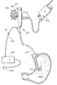
- FIG. 1 is a vertical cross-sectional view showing the use of the invention in the stomach.
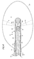
- FIG. 2 is a view similar to FIG. 1 showing an elliptical balloon in use for positioning a radiation source in the stomach.
- FIG. 3 is a diagrammatic, longitudinal, cross-sectional view of an instrument and supporting equipment in accordance with one form of the invention.
- FIG. 4 is an enlarged longitudinal cross-sectional view of the distal end of an instrument in accordance with one form of the invention.
- FIG. 5 is a vertical cross-sectional view taken on line 5 - 5 of FIG. 4.
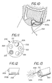
- FIG. 6 is a vertical cross-sectional view of another form of the invention shown as it appears during use in the stomach.
- FIG. 7 is a transverse cross-sectional view taken on line 7 - 7 of FIG. 6 but on a larger scale.
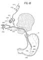
- FIG. 8 is a cross-sectional view of the invention in use with a radioactive isotope employed for providing radiation.
- FIG. 9 is a vertical cross-sectional view showing the use in the stomach of another form of the invention.
- FIG. 10 is a vertical cross-sectional view showing the use of the invention of FIG. 9 in the colon.
- FIG. 11 is an end view taken on line 11 - 11 of FIG. 1 on a larger scale.
- FIG. 12 is a side elevational view showing the distal end of the shaft of the instrument with a lamp as a radiation source, partially extended from the end of the instrument shaft.
- FIG. 13 is a perspective view similar to FIG. 12 with the lamp fully extended to a deployed position ready for use.
- FIG. 14 is a side elevational view partly in section showing the lamp enclosed in an optional inflated balloon.
- FIG. 15 is a perspective view of a lamp enclosed in a protective screen.
- FIG. 16 is a perspective view similar to FIG. 15 but partly broken away to show the inner structure
- FIG. 17 is a perspective view showing the use of a lamp of a larger size as a radiation source.
- FIG. 18 is a semi-diagrammatic cross sectional view of the human body showing one preferred form of the invention during use.
- FIG. 19 is an exploded side elevational view partly in section showing one form of light source on a larger scale than in FIG. 18.
- FIG. 20 is a vertical cross-sectional view showing the light source and diagrammatic representation of the paths of light radiation from the light source.
- FIG. 21 is a cross-sectional view taken on line 21 - 21 of FIG. 20
- FIG. 22 is a perspective view of another form of light source.
- FIG. 23 is a perspective view of the light source of FIG. 22 showing reflectors used to condense the light radiation.
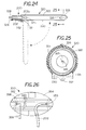
- FIG. 24 is a diagrammatic longitudinal sectional view of a modified form of light source mounted on the distal tip of the endoscope shaft 202 .
- FIG. 25 is a cross-sectional view taken on line 25 - 25 of FIG. 24 on a larger scale.
- FIG. 26 is a diagrammatic transverse sectional view showing an optional form of condenser for coupling light radiation between the light source and the proximal end of the endoscope 202 .
- the therapeutic method in accordance with the present invention is suited for use in various body cavities including, but not limited to, the stomach, the bowel, the lungs, the peritoneal cavity, the urinary tract, and can also be used with various devices, fabrication methods, arrangements, systems and methods of employment which irradiate the walls of various body cavities or interior sites within the body of a patient by means of radiation in sufficient amount to debilitate or kill microorganisms lining the body cavity in which the invention is used.
- an x-ray device which includes components for producing localized x-ray radiation within a vacuum housing or tube and, optionally, including an inflatable balloon surrounding the vacuum housing and preferably connected near the distal end of the device for positioning the source of radiation as well as for expanding the walls of the body cavity.
- the invention can be employed for killing or debilitating various pathogenic microorganisms, it can be used to advantage in treating Helicobacter pylori infections of the gastrointestinal system and other ailments in which radiation is to be delivered to portions of the body that are not easily accessible.
- the present invention will be described by way of example in the treatment of Helicobacter pylori infections within the stomach. It should be understood, however, that the invention is not limited to specific apparatus or methods described.
- Helicobacter pylori is an infection of the stomach and duodenum and the major cause of stomach ulcers.
- Various forms of radiation including x-rays, radiation from isotopes, radio waves, microwaves, or light radiation, e.g., ultraviolet light in accordance with the invention provide an advantageous method of treating such infections.
- the x-ray device for example, produces radiation that penetrates the lining of the body cavity, in this case the columnar epithelial lining of the walls of the stomach, or the epithelium of any other passage or lumen that is being treated. During this treatment, the radiation produces apoptosis or programmed cell death in which the DNA of the microorganism is rendered unable to divide.
- the apoptosis that occurs in the microorganisms is different from necrosis, another type of cell death.
- a disruption of the gene structure of the microorganism prevents it from further replication. Consequently, the microorganisms die by mutation and, in some cases, by the disruption of metabolic processes at the cellular level. Some fraction of the microorganisms may also be killed immediately by the radiation.
- An important advantage of the invention lies in the fact that many organisms, such as bacteria, are extraordinarly sensitive to radiation, sensitive to a much greater degree than the surrounding human cells. Accordingly, the bacteria can be killed or debilitated by apoptosis without serious destruction of the host cells.
- a source of radiation such as an x-ray device is positioned in a body cavity, e.g., the stomach, for treating H. pylori infections by inducing apoptosis in the bacterial cells carried on or within in the epithelium lining the stomach.
- the x-ray or other radiation of the present invention can therefore be used to prevent the escalation of the infection to stomach ulcers and cancer.
- FIGS. 1 - 4 illustrate by way of example one method of use in accordance with the present invention; the treatment of Helicobacter pylori infections of the stomach designated by the numeral 5 .
- Numeral 5 a indicates the esophagus and numeral 5 b indicates the pyloric sphincter.
- an instrument 6 is provided which includes a flexible supporting cable or shaft 7 and a distal radiation distribution head 8 from which radiation emanates as shown by rays 9 that strike the adjacent lining of the stomach where the H. pylori infection thrives in the epithelium and mucous lining the stomach 5 .
- the source of radiation is an x-ray device 10 that includes a cathode 16 , an anode 18 , and a getter 24 , all disposed within a vacuum chamber or tube wall 28 (see especially FIGS. 3 and 4).
- the cable or shaft 7 permits a physician to maneuver the x-ray device 10 to the treatment site in the body. It is contemplated that different types of maneuvering devices could be employed to position the head 8 containing the x-ray device 10 which provides the radiation, depending upon the particular site to be treated.
- the shaft 7 In the embodiments showing the use of the instrument 6 in the stomach and gastrointestinal system, it is helpful for the shaft 7 to be flexible, to have a reduced diameter and rounded forward end such that it can be easily introduced into the esophagus and stomach, either by itself or, if desired, through an appropriate flexible endoscope (not shown).
- the shaft 7 will have an outer diameter of less than or equal to approximately 3 mm, allowing it to fit easily within a standard endoscope that typically has a working lumen diameter of about 3 mm. In other applications, the properties and dimensions of the shaft 7 may vary to meet the requirements of the task.
- an annular or donut-shaped radiation pattern 9 is ideally suited for treatment.
- many passages and other interior portions of the body need to be dilated while treatment is carried out with radiation from the x-ray device 10 .
- the stomach is very soft and, except after a meal, is in a collapsed state.
- Rugae or folds 5 c are present on its inner walls.
- Stomach ulcers resulting from an H. pylori infection are shown at 5 d .
- an optional dilating balloon 20 can be provided, if desired, to dilate the passage of the body, such as the stomach, and thereby distend the stomach wall and hence spread the rugae 5 c apart and thus flatten the stomach wall so that a uniform annular radiation pattern can be created.
- the balloon 20 can also be important in positioning and holding the distribution head 8 in the desired location, especially in a central position that is equidistant from all parts of the surrounding stomach wall so as to provide the same dose of radiation to all portions of the stomach 5 surrounding the distribution head 8 .
- the balloon 20 can be in fluid communication with a fluid loop 22 that is disposed within the shaft 7 to carry fluid from outside the body to the interior of the balloon 20 , and provide a return path for the fluid. If desired, the fluid in loop 22 can circulate in the interior of the balloon 20 , inflating the balloon 20 , and can then be returned to the proximal portion of the shaft 7 through the fluid loop 22 .
- a circulating pump 34 can be used to circulate the fluid and maintain the pressure required to achieve the desired balloon size.
- the pump 34 can be coupled to the fluid loop 22 via fluid ports 35 .
- Other methods and devices known in the art may also be used to circulate the fluid and inflate the balloon 20 .
- a separate inflation lumen 40 and port 42 are shown in FIGS. 3 and 4 in fluid communication with the balloon 20 .
- the fluid loop 22 is positioned to circulate cooling fluid in heat conducting relationship with the anode 18 .
- the fluid loop 22 extends to surround a portion of the anode 18 .
- the circulating action of the fluid loop 22 can thus provide a constant cooling rate, regardless of the extent of balloon dilation.
- the separate inflation lumen 40 can be coupled to a fluid source of adjustable pressure for the balloon 20 via the inflation port 42 .
- the fluid loop 22 and the inflation lumen 40 are created using plastic extrusion techniques.
- This arrangement has the advantage of allowing a liquid, e.g., water, to be used in fluid loop 22 for cooling and a gas, e.g., air, to be used for balloon inflation via lumen 40 so that the radiation from head 8 is not absorbed before reaching the stomach wall.
- a liquid e.g., water
- a gas e.g., air
- an inflation fluid is provided to expand the balloon 20 via lumen 40 , inflation port 42 and a line 33 , which is connected, to the pump 34 .
- the liquid e.g., water or saline
- a gas is, however, preferred for filling the balloon 20 , since it will have a negligible tendency to attenuate the radiation 9 emitted from the energy supply head 8 .
- the coolant is circulated separately through the fluid loop 22 via lines 37 and 39 by means of circulating pump 34 ′.
- the pumps 34 and 34 ′ are controlled by the power supply 36 which also supplies the high voltage current through the coaxial cable via coupling 38 to a cathode 16 and an anode 18 that are contained within a vacuum tube or chamber 28 .
- the power supply 36 also includes an x-ray detector of suitable known construction that is used to calibrate the output of the device and control dosimetry, as well as an electronic display, if desired, for monitoring the therapy.
- the anode 18 and cathode 16 are coupled to the power supply or high voltage source 36 .
- a coaxial cable is disposed within the flexible shaft 7 and coupled to the high voltage source 36 at the proximal end of the shaft 7 .
- An internal conductor 30 of the coaxial cable is coupled to the anode 18 at the appropriate voltage and is enclosed in an insulating layer 31 .
- An external conductive layer 32 of the coaxial cable is held at ground and coupled to cathode 16 .
- a conductive solder on the outside of the vacuum chamber wall 28 may be used to couple the cathode 16 to the external conductive layer 32 .
- Other known methods may also be used to apply an electric potential across the anode and cathode.
- the vacuum tube 28 containing the cathode 16 and anode 18 can be of the thermonic type, with x-ray energies of, say, 8 KeV to 20 KeV.
- the tube can be powered to utilize 3 watts or less to produce soft x-ray radiation. A typical treatment time at 3 watts is about one to 20 minutes.
- the x-ray tube is turned off and the x-ray distribution head 8 is removed.
- a radioactive isotope source is used instead of an x-ray source, the tissue is exposed to radiation for a few minutes, usually from about 15 minutes to 30 minutes.
- the stomach in its relaxed state has a diameter of about 5-6 centimeters and cannot accommodate a rigid structure.
- the device of the present invention can be inserted by being passed through a standard flexible laryngoscope or endoscope (not shown) that has a working lumen about 3 millimeters in diameter. Therefore, a coaxial cable used in this device must have a diameter small enough to be accommodated within the passage to be treated or within the scope-device used, and it must be able to carry the required voltages and have sufficient flexibility to make turns as it follows the passage. A diameter of less than or equal to 3 millimeters may be used for most applications. Standard high voltage coaxial cables are generally not flexible enough.
- Miniature high frequency coaxial cables are available with an outer diameter of approximately 1.0 mm to 3.0 mm which also exhibit sufficient flexibility and can carry the required voltage without breakdown.
- a cable with an outer diameter of less than or equal to about 3 mm is used. Cables approximately 1-2 mm in diameter are also available, and are used in other embodiments.
- Such cables are manufactured by, for example, New England Electric Wire Corporation, Lisborn, N.H.
- a getter 24 is disposed within the vacuum housing 28 in order to aid in creating and maintaining a vacuum condition of high quality.
- the getter 24 has an activation temperature at which it will react with stray gas molecules in the vacuum. After the vacuum housing is assembled under vacuum conditions and the housing pumped out or baked out, the device is heated to the activation temperature and maintained at that temperature for several hours. It is desirable that the getter used have an activation temperature that is not so high that the x-ray device will be damaged with heated to the activation temperature.
- An SAES ST 101 alloy getter may be used, which has an activation temperature in the range of 750° C. to 900° C. and is composed of approximately 64% zirconium and 16% aluminum.
- An ST 707 alloy getter also may be used, which has an activation temperature in the range of 300° C. to 500° C. and is composed of approximately 70% zirconium, 18.6% vanadium, and 5.4% iron.
- Other suitable getters such as alkali metals can be used, if desired.
- a heavy metal material such as tungsten or gold can be used for the anode 18 .
- the cathode and anode will be shaped to produce the desired radiation pattern.
- the anode 18 is cylindrically shaped with a flat, circular side disposed toward the cathode 16 , and the edge is rounded.
- the cathode 16 of this embodiment is cone-shaped.
- a wall of the vacuum chamber 28 should be transparent to x-rays in order to allow the full dosage to reach the wall of the body cavity being treated.
- the wall 28 can comprise pyrolytic boron nitride, or another metal or ceramic material which is transparent to x-rays. Other possibilities include beryllium, beryllium oxide, aluminum, aluminum oxide, or graphite.
- the outer diameter of the x-ray device is sized as large as, say, 1 centimeter to deliver the localized radiation to the interior of the stomach. In another embodiment, the outer diameter of the x-ray device is less than or equal to about three millimeters.
- the diameter of the dilated balloon 20 should be able to vary with the pressure applied, so that the diameter of the balloon can be adjusted to fit the size of the patient's stomach or other passage. Therefore, an elastic balloon is particularly suited to gastric applications, where the elastic material will conform to the many surface features of the stomach and dilate the stomach more completely. However, in other applications, it may be desirable to employ an inelastic balloon with a fixed dilated diameter. It should be noted in FIG. 1 that the balloon 20 , when present, is preferably secured to the flexible shaft 7 , e.g., by means of a suitable adhesive 21 at a distance 7 a from source 8 a and also spaced from the radiation head 8 .
- the distal end of the balloon 20 is free rather than being connected to the distribution head 8 or to anything else and is spaced from the source 8 a of radiation by a distance 7 b that is equal to 7 a .
- the distances 7 a and 7 b each equals the approximate radius of the balloon 20 so as to locate the source 8 a of the radiation 9 at the center of balloon 20 , thus equalizing radiation flux in all directions.
- a round balloon is shown in FIG. 1.
- an electric field exists at the cathode 16 , while on the outside of the vacuum housing a conductive braid or solder is held at ground. These two potentials can be insulated from each other to reduce the chance of electrical flashover.
- a vacuum tube wall of pyrolytic boron nitride can provide some insulation. If a metal is used as the wall of the vacuum chamber 28 , an insulating layer is beneficial to decrease the chance of electrical flashover.
- an electrically insulating material can be placed at the joints on the outside of the vacuum chamber wall 28 .
- the insulating material could be a potting compound, an injection-molded polymer, and other materials with electrically insulating properties.
- the vacuum chamber further includes a biocompatible outer coating, such as polyethylene or Teflon® material.
- the joints between the vacuum chamber wall 28 and the anode 18 may be vacuum furnace brazed, or may be sealed by conventional crimping methods.
- the cathode 16 of the present invention consists of a material which displays emission characteristics when an electrical field is applied.
- One possible cathode material is a thin diamond film, which can be formed using conventional chemical vapor deposition techniques.
- a diamond film also may be formed using a laser ion source as described in U.S. Pat. No. 4,987,007 to Wagal, the contents of which are incorporated herein by reference.
- a graphite target and the substrate to be coated are disposed in a vacuum chamber. Between the two is an accelerating grid held at a high negative potential.
- the graphite target is radiated with a focused laser beam from a pulse laser.
- the laser beam ejects a plume of carbon vapor from the graphite target. A portion of the atoms in the plume are ionized by the focused laser beam, and the positive carbon ions are accelerated towards the substrate by the accelerating grid.
- cathode material is described in U.S. patent application entitled “DEVICE FOR DELIVERING LOCALIZED X-RAY RADIATION TO AN INTERIOR OF A BODY AND METHOD OF MANUFACTURE”, having Ser. No. 08/806,244, the contents of which are incorporated herein by reference.
- the cathode material is a coating of carbon having diamond-like bonds which demonstrate negative electron affinity. It is also desirable to have sufficient conductivity to create a constant supply of electrons to the surface of the cathode. The presence of some graphite bonds in the diamond film will contribute to conductivity.
- a combination of a diamond film having both sp3 carbon bonds, to function as a cathode, and some sp2 carbon bonds, to facilitate conductivity, is particularly suited for use in many applications.
- Other elements may also be present in the film in small quantities.
- the diamond film will have the property that it can emit electrons at electrical fields greater than or equal to about 20 KV/micron. This required electric field is significantly lower when compared to that required for metal emitters such a molybdenum or silicon, which require greater than 1,000 KV/micron.
- the x-ray device and method can be constructed as described in co-pending patent application Ser. No. 09/027,010 (in which I am a co-inventor) and is incorporated herein by reference.
- the x-ray device When used to radiate the walls of an interior passage of the body, according to one embodiment of the invention, the x-ray device may be placed within a standard endoscope or laryngoscope. The x-ray device or other radiation described herein is introduced into the passage to be treated. The x-ray device, etc., is then guided through the passage, using techniques known in the art, until it is positioned near the area to be irradiated. The site to be irradiated may be viewed through the endoscope, and the area around the device may be flushed using the endoscope, if necessary.
- the dilating balloon 20 is then inflated by fluid, either liquid or gas, from the fluid pump to the desired diameter to expand the body cavity, in this case the stomach so as to hold the radiation distribution head 8 in the desired location and spread the rugae 5 c apart so as to thereby flatten the stomach wall to insure uniform irradiation.
- fluid either liquid or gas
- the high voltage generator is activated and an electrical field is established across the cathode 16 and the anode 18 .
- the cathode 16 emits electrons which are accelerated toward the anode 18 .
- electromagnetic radiation is emitted.
- x-ray radiation is produced by the Bremsstrahlung effect.
- the x-ray radiation impinges upon the wall of the body cavity, such as the stomach the H. pylori living on the surface of the passage are killed or debilitated by apoptosis as discussed above.
- H. pylori living on the surface of the passage are killed or debilitated by apoptosis as discussed above.
- the apoptosis eliminates the bacterial cells and reduces inflammation as well as the biochemical results of inflammation, thereby preventing ulcers, gastritis and cancer.
- the voltage source is turned off and the balloon 20 , when present, is deflated. The device is then withdrawn from the body.
- the dosage of x-ray radiation to be applied to the interior of a body will generally be within the scope of the attending physician's judgment and will be based on individual conditions, such as the severity of the infection and the damage that has occurred at the site to be treated and the particular patient. In order to treat H. pylori , only the surface of the epithelium needs to be irradiated.
- x-ray radiation typically in the range of 0.1 to 50 Grays, and most preferably 1-2 Grays, may be applied.
- the treatment is typically structured to last about 2 to 10 minutes, and most preferably, 3 to 5 minutes.
- the x-ray emitter may be repositioned by moving it from one part of the stomach to another, either continuously or intermittently during the course of radiation treatment, depending on the length of the area requiring treatment.
- the source of radiation in the distribution head 8 is at the center of the balloon 20 , all of the rays 9 will be of the same length when they strike the microorganisms, thereby assuring uniform radiation flux and, consequently, uniform exposure to radiation wherever the radiation strikes the wall of the cavity that is being treated. Uniform radiation exposure is also aided through the flattening of the stomach wall that is accomplished by the expansion of the balloon 20 .
- the expanded balloon 20 also locks or wedges the radiation-supplying head 8 in place within the stomach 5 , so that stomach contractions, which take place normally, cannot displace the instrument 6 .
- the balloon 20 should not be expanded to the point where the blood supply to the epithelium lining the stomach is cut off, since oxygen is necessary in forming free radicals which are important in the destruction of the microorganisms.
- FIG. 2 illustrates a positioning balloon 20 of a different shape.
- the balloon 20 is generally elliptical in shape and is secured as already described in FIG. 1 by means of adhesive 21 at a distance 7 a from the energy-supplying head 8 , the space 7 a being a substantial distance that is determined so as to place the energy distribution head 8 in approximately the center of the elliptically-shaped balloon 20 .
- the axis of the ellipse is aligned with the distribution head 8 .
- radially extending tethers 23 that serve as positioning ligaments can be bonded at each end to extend between the distribution head 8 and the wall of the balloon 20 .
- the tethers 23 can be formed from short lengths of cord, tape or narrow strips of cloth, etc. Other positioning means for locating the head 8 at the center of the balloon 20 will be apparent to those skilled in the art.
- the tethers 23 can be attached to the balloon 20 by adhesive during assembly while the balloon is inverted, i.e., inside out over the distal end of the distribution head 8 . Refer now to FIGS.
- ultra-violet light rays 60 are provided by the energy distribution head 8 which is formed from a transparent material, e.g., glass or fused quartz.
- the ultraviolet light 60 is projected both laterally at 61 as well as passing forwardly at 62 through the balloon 20 striking the wall of the stomach 5 .
- the balloon 20 holds the radiant energy distribution head 8 in the desired position and also distends the wall of the stomach 5 so as to spread out the rugae 5 c and thereby allow uniform exposure of the portion of the wall of the stomach that is being treated.
- the ultraviolet light rays 60 strike the columnar epithelium lining the stomach, the H.
- the part of the stomach exposed to the ultraviolet light rays 60 can be changed by the physician, either by moving the balloon 20 and head 8 along the length of the stomach 5 toward the esophagus 5 a or by changing the angle of the head 8 with respect to the longitudinal axis of the stomach 5 as will be described more fully below.
- the position of the instrument can also be confirmed using fluoroscopy or a CAT scan, if desired.
- the cathode 16 and anode 18 , as well as the conductor 30 are eliminated and replaced by a fiber optic bundle 64 (FIG. 7) which extends from a light source 66 (FIG. 6) through the entire length of the flexible shaft 7 via the esophagus 5 a into the stomach 5 , so as to carry ultraviolet light from the source 66 through the distribution head 8 to a light reflector or diffuser, e.g., of conical shape, inside the distribution head 8 which spreads the ultraviolet light rays 60 so that they pass through the balloon 20 , striking the wall of the stomach 5 to the side and in front of the distribution head 8 .
- a fiber optic bundle 64 FIG. 7 which extends from a light source 66 (FIG. 6) through the entire length of the flexible shaft 7 via the esophagus 5 a into the stomach 5 , so as to carry ultraviolet light from the source 66 through the distribution head 8 to a light reflector or diffuser, e.g., of conical shape, inside the distribution
- the flexible shaft 7 can be provided with a plurality of longitudinally extending, radially spaced apart cables 68 that are slidably mounted in the flexible body portion 70 of the shaft 7 .
- the distribution head 8 can be made to point toward the right, left or up and down as directed by the physician to distribute the beam of ultraviolet light to various parts of the stomach as desired.
- the shaft 7 can be enclosed in a protective cover or sheath 74 , e.g., polypropylene plastic that will slide easily through the esophagus 5 a.
- the ultraviolet light source 66 can comprise any suitable commercially available lighting source, e.g., a mercury vapor lamp.
- a mercury vapor lamp There are three classes of ultraviolet light: UVA (320 nanometers to 400 nanometers), UVB (290 nanometers to 320 nanometers), and UVC (200 nanometers to 290 nanometers).
- UVA can be provided from an incandescent source such as a tungsten, halogen or quartz iodide lamp.
- UVB can be provided by means of a suitable arc lamp such as a high pressure mercury lamp or a hot quartz lamp.
- UVC can be provided from an arc lamp using mercury vapor, a cold quartz lamp or a carbon arc lamp which mimics sunlight with a spectrum of from 280 nanometers to near infra-red. While any suitable ultraviolet light beam can be provided, it is preferred to use UVB or UVC light because of their greater effectiveness in killing or debilitating microorganisms through apoptosis.
- the shaft 7 and head 8 are passed through the esophagus 5 a conventionally with the balloon 20 in a collapsed position surrounding the head 8 .
- the balloon 20 is inflated by passing a suitable fluid, e.g., air, through the inflation lumen 40 until the balloon 20 has expanded the stomach 5 at the desired location, thereby distending the rugae so that the pockets otherwise present are spread out evenly over the surface of the balloon 20 .
- the light source 66 is then turned on, causing the UV light to pass through the fiber optic bundle 64 and out through the distribution head 8 .
- the distribution head 8 and the balloon 20 can then be repositioned in the stomach as desired to expose all of the infected areas or, alternatively, the control cables 68 can be manipulated so as to point the head 8 toward the areas of the stomach that require treatment. Observations can be carried out by means of a viewing port and eyepiece 72 of known construction or through a separate endoscope (not shown) that is passed through the esophagus 5 a into the stomach 5 alongside the flexible shaft 7 .
- the same apparatus is employed as already described in FIGS. 6 and 7, except that the light source 66 comprises a suitable commercially available infrared light source.
- the light source 66 can, for example, be an erbium laser, which is preferably operated intermittently and on low power compared to the power used for removing skin blemishes, scars, tattoos, etc., to enable the microorganisms to be killed without damaging the surrounding tissue.
- FIG. 8 illustrates the use of the invention with radioactive isotopes to provide radiation for killing or debilitating H. pylori or other microorganisms through apoptosis.
- Radioactive isotopes provide the electromagnetic radiation through radioactive decay that can expose healthcare workers to radiation and require a shielded room.
- the present invention provides a way of shielding the isotope before and after use.
- the flexible shaft 7 has a body portion 80 that is uniform throughout and contains a longitudinally extending lumen 82 in which a control cable 84 is slidably mounted.
- the distal end 86 of the control cable 84 is secured to a cylindrical slug 88 that is formed mostly of a shielding material such as lead but has a central portion 90 which is formed from a radioactive isotope.
- the slug 88 is slidably mounted in a bore 92 within the energy supply head 8 which includes two shielding portions including a distal portion 94 and a proximal portion 96 , both formed of a suitable shielding material such as lead that is useful in shielding radioactive material.
- the shields 94 , 96 are joined by an annular central portion 98 formed from a radiation-transparent material such as a suitable ceramic or plastic resinous material which allows radiation to be emitted when the slug 88 is moved under the direction of the physician distally so that the radioactive isotope 90 is exposed in the radiation transparent area 98 at the center of the distribution head 8 .
- the distribution head 8 is enclosed in a sheath or coating of biocompatible material 100 such as polyethylene or Teflon®.
- the shaft 7 and head 8 are inserted through the esophagus 5 a into the stomach 5 conventionally, with the balloon 20 in a collapsed condition.
- Inflation fluid is then forced through the inflation lumen 40 into the balloon 20 to expand it sufficiently to spread out the walls of the stomach as described above.
- the cable 84 is then moved distally so as to shift the slug 88 containing the radioactive isotope 90 downwardly in FIG. 8 until the radioactive material 90 is aligned with the annular radiation-transparent wall 98 , thereby allowing the radiation to pass from the radioactive isotope 90 radially in all directions from the head 8 .
- the radiation After passing through the balloon 20 , the radiation will strike the wall of the stomach 5 or other body cavity, killing or debilitating the H. pylori or other pathogenic microorganisms lining the wall of the cavity being treated.
- the balloon 20 and/or head 8 are repositioned under the control of the physician so as to redirect the radiation to the desired areas and for the length of time required to accomplish the required treatment. Because bacteria are much more sensitive to radiation than human tissue, the H. pylori and other bacteria can be killed or debilitated by apoptosis with little, if any, damage to the host tissue.
- the instrument shown in FIG. 8 can be positioned in any suitable manner, e.g., by observation through an endoscope (not shown) that is inserted through the esophagus alongside the shaft 7 into the stomach 5 .
- any of the instruments 6 (including the shaft 7 , head 8 and balloon 20 ) of FIGS. 1 - 8 can be inserted into the body cavity alone or, if desired, through the lumen of a commercially available endoscope of suitable known construction.
- Isotopes emit radiation through the phenomenon of nuclear disintegration
- the radiation supplied by the isotope 90 can be either beta or gamma radiation.
- the beta radiation does not have the penetrating power of the gamma radiation, which will pass entirely through the body and into the room surrounding the patient, therefore requiring a radiation-shielded operating room. It is preferred that the radiation used have relatively shallow penetrating power, since there is usually no reason to go to any substantial depth.
- H. pylori for example, is located on the surface of the epithelium lining the stomach. It is contemplated in accordance with the present invention to select the penetration depth of the radiation so that it penetrates only into the surface layer where the H. pylori is located, thereby protecting the patient from unnecessary radiation damage. For that reason, when an isotope is used to supply radiation, beta radiation is preferred to gamma radiation because of its reduced penetrating power.
- the use of non-radioactive sources is preferred to the radioactive source described in connection with FIG. 8, since the use of radioactive sources requires special handling, environmental considerations, and is subject to greater radiation danger.
- radioactive sources In the United States, only radiation oncologists can prescribe a therapy and dose involving radioactive isotopes.
- gamma sources require a shielded catheterization laboratory. Because of the penetrating power of gamma radiation, the healthcare workers must leave the room while the patient is being treated.
- the isotope 90 can comprise radioactive iridium-192 (Ir 92 ) which is available in the hospital because of its use in cancer treatment.
- Beta sources typically have a soft tissue penetration depth of less than 1.25 cm. and therefore reduce the unwanted exposure of healthy tissue compared to gamma radiation. Beta sources are also easier to handle than gamma sources and pose a smaller risk to the patient and healthcare worker.
- Radio waves and microwaves can also be used in accordance with the invention for destroying pathogenic microorganisms such a H. pylori in the lining of a body cavity.
- Microwave energy can be supplied to the distribution head 8 of the device shown in FIGS. 6 and 7 by removing the fiber optic bundle 64 to provide a hollow wave guide through the flexible shaft 7 for conveying microwave energy from a suitable magnetron at the source 66 to the radiant energy distribution head 8 where it is directed through the balloon 20 onto the walls of the body cavity surrounding the head 8 .
- the microwave energy is preferably adjusted to heat the inner surface of the body cavity so as to preferentially kill bacteria and other microorganisms living at the surface or lining of the body cavity.
- Radio wave energy can be provided using the apparatus of FIGS. 3 and 4, but without a vacuum in the tube 28 between the electrodes 16 and 18 .
- a radio frequency field can be set up between the electrodes 16 and 18 to produce heating of the body tissue when the body tissue is placed adjacent to or between the electrodes.
- a powerful RF oscillator can be applied across the electrodes 16 and 18 so as to heat the body tissue between them, as the body tissue acts as a dielectric of a capacitor in which dielectric losses cause heating within the tissue.
- the RF oscillator can, if desired, be followed by RF amplifier stages for generating high frequency currents that produce heat within the part of the body cavity that is being treated for destroying the pathogenic bacteria on or within the tissue.
- Other forms of radio wave energy known to those skilled in the art can also be used for destroying microorganisms.
- the balloon 20 can be eliminated since it is generally desirable to position the tissue being treated against or between the electrodes 16 and 18 .
- FIGS. 9 - 16 Other forms of the invention will now be described in connection with FIGS. 9 - 16 . Refer now especially to FIGS. 9 - 12 .
- FIG. 9 a surgical instrument 200 which has a control head 201 , a shaft 202 which in this case is flexible, a light source 204 for viewing, and a radiation source comprising a lamp 206 which is connected by means of a cord 208 to a power supply 209 .
- the instrument 200 including the shaft 202 , control head 201 and viewing lamp 204 , can be any suitable conventional and commercially available endoscope, preferably of the type having control knobs 205 and 207 for controlling the angular positioning of the instrument head or tip 202 a .
- the shaft 202 of the instrument 200 has a longitudinally extending passage indicated at 212 , the distal open end of which is shown in FIG. 11.
- Electrically insulated conductors 208 a and 208 b are held in the cord 208 which is itself slidably supported in the passage 212 so that the lamp 206 can be withdrawn into the shaft 202 or extended to a deployed position by means of a handle 211 (FIG. 9) as shown in FIG. 13 when it is to be used.
- the electrical conductors 208 a and 208 b are connected at their proximal ends to the suitable power supply 209 .
- the power supply 209 can be of any suitable known, commercially available construction including an energy storage capacitor and a triggering circuit, preferably a computer-controlled triggering circuit.
- a preferred lamp 206 comprises either an ultraviolet lamp, such as a low pressure mercury vapor lamp, or a flash lamp formed from fused quartz, e.g. a xenon arc flash lamp, that can be made to pulse or flash periodically at selected timed intervals.
- an ultraviolet lamp such as a low pressure mercury vapor lamp
- a flash lamp formed from fused quartz e.g. a xenon arc flash lamp
- One preferred lamp comprises a filtered short-arc xenon lamp as a radiation source for producing ultraviolet radiation. While radiation at various wavelengths can be used, one preferred range is ultraviolet light of about 200-400 nm.
- the flash lamp 206 is operated by a triggered discharge of energy from the electrolytic storage capacitor contained in the power supply 209 to produce a very short burst of high intensity light.
- the power supply 209 is provided with AC power from a wall plug 209 a .
- a computerized control also contained in the power supply 209 actuates a triggering circuit which causes the xenon gas to suddenly become a low resistance path, at which time the energy stored in the electrolytic capacitor discharges through the flash lamp or tube 206 , resulting in a short duration, brilliant, burst of light radiation that contains ultraviolet light.
- the computer causes the lamp 206 to flash at selected timed intervals, e.g., every five seconds, but the interval can be changed as desired by reprogramming the computer.
- the radiation from lamp 206 spreads out through a complete circle of 360° in all directions, to thereby debilitate or kill the pathogenic microorganisms, e.g. H. pylori that are present in the stomach.
- the invention is shown during use in the stomach in FIG.
- FIG. 10 the invention is shown in the colon for killing or debilitating pathogenic organisms that are present in cases of inflammatory bowel diseases such as ulcerative colitis, Crohn's disease or cytomegalovirus ulcers.
- the digestive tract is repopulated with probiotic bacteria, i.e., innocuous bacteria to which the body does not react adversely.
- probiotic bacteria are administered indefinitely with meals to reestablish a harmless flora that approximates the flora found in the gut under normal conditions.
- the probiotic is administered either as tablets or capsules, typically taken three times a day indefinitely or until the natural background flora of the digestive tract is reestablished.
- FIG. 11 illustrates in more detail the construction of the lower end of the shaft 202 of the endoscope 200 .
- Illumination is provided conventionally by the light source 204 through fiber optics to illumination ports 220 and 222 to enable the surgeon to see clearly through a viewing port 224 where radiation is to be applied.
- the endoscope 200 can also be provided with a spray nozzle 226 for washing debris away from the area around the end of the shaft 202 or for cleaning the lamp 206 .
- the lamp 206 is withdrawn into the shaft 202 as shown in FIG. 12 by means of a handle 211 so that the lamp 206 is either completely or almost completely recessed inside the lower end 202 a of the shaft 202 .
- the lamp 206 when the lamp 206 is to be used, it is extended as far as desired by the surgeon to a deployed position as shown in FIG. 13, allowing the light radiation to be transmitted in all directions.
- FIG. 14 illustrates an optional inflatable balloon 230 surrounding the lamp 206 and secured, e.g., by means of a suitable medical adhesive at 232 , to the end of cord 208 which contains electrical conductors 208 a and 208 b and an air passage 208 c for inflating the balloon 230 after the lamp 206 has been inserted into the stomach or bowel for positioning and stabilizing the lamp 206 in the body cavity as described hereinabove.
- FIGS. 15 and 16 illustrate the lamp 206 in more detail
- FIGS. 15 and 16 show how the lamp 206 is contained within a tubular quartz enclosure 206 a which serves as a shield for filtering out heat radiation but, if desired, can also be used to restrict the wavelength of the light transmitted to the lining of the body cavity to a desired range.
- the lamp 206 could in some cases become fairly warm over extended periods of use.
- a protective screen 206 b is placed around the quartz shield 206 a .
- Screen 206 b can be formed from any suitable material such as plastic, metal or other material including synthetic fibers, e.g., carbon or Kevlar®, embedded in a plastic matrix.
- FIG. 17 a flash tube of a size larger than lamp 206 is provided.
- the tube 231 is about the same diameter as the shaft 202 . It is rigidly, i.e. directly, connected by means of a coupling at 233 to the tip 202 a of the shaft 202 of the endoscopic instrument 200 and is positioned by manipulating the tip 202 a through the use of cable controls 205 and 207 .
- the cord 208 is not slidably supported in shaft 202 .
- the lamp 230 is surrounded by a protective screen 235 to prevent it from coming in contact with the lining of the stomach or bowel in case it becomes heated during use or breaks.
- stomach discomfort including stomach discomfort, “heart burn,” and/or pain
- a tentative diagnosis by the physician of stomach ulcers is made which is later confirmed by an endoscopic examination. The diagnosis can then be further confirmed with standard enzymatic tests to detect the presence of H. pylori . Treatment using the present invention is then begun. Following standard sedation, the shaft 202 of the endoscope 200 is inserted through the esophagus (FIG. 9).
- the head or tip end 202 a of the shaft 202 is then positioned as required under the supervision of the physician and the power supply 209 is turned on, thereby activating the computer contained in the power supply 209 and causing the capacitor to discharge periodically through the mercury vapor or xenon arc lamp 206 , e.g., once every five seconds until treatment is concluded.
- the lamp 206 is repositioned as necessary to provide adequate treatment to all of the affected areas, until the bacteria are either killed or incapacitated.
- the instrument 200 is then withdrawn.
- the bowel is cleansed conventionally.
- the patient is sedated in the usual manner, and the shaft 202 of the endoscope 200 is then inserted through the rectum and advanced to the infected area to be treated (FIG. 10).
- the distal end 202 a of the instrument 200 is then positioned where treatment is required and the lamp 206 is extended from a recessed position as shown in FIG. 12 to the extended position of FIG. 13 in proximity to the lesions on the lining of the colon that require treatment.
- the lamp 206 is then actuated to produce a series of flashes that provide optimum exposure to the light radiation until the pathogenic bacteria are killed or debilitated.
- the patient is then placed on a regimen of probiotics as already described for an indefinite period so as to reestablish the growth of innocuous flora within the bowel.
- an antibiotic prep is used following a mechanical prep.
- a light-sensitizing medication is administered to the patient so that the light is preferentially absorbed by the bacteria within the colon, rather than by human cells.
- Any suitable light-sensitizing medicine can be used, such as any of the suitable protoporphyrin compounds known to those skilled in the art for preferentially absorbing the ultraviolet radiation so as to provide a more effective bactericidal action.
- the light source 240 comprises a xenon flash lamp or tube 242 which is wired by means of conductors 243 - 245 to a suitable power source 246 .
- the conductors are supported by an insulator 248 which is connected by means of a bracket 250 to a circular cap 252 that during use is placed over the open end of a conical reflector 256 having a highly reflective inner surface 258 .
- the power supply 246 can comprise any commercially available flash lamp power supply preferably one with a direct current supply for charging one or more flash lamp capacitors that discharge periodically through the flash tube 242 .
- the capacitors contained in the power supply 246 discharge at regular intervals e.g., about once every one to ten seconds to produce a series of flashes of ultraviolet light of mixed wavelengths.
- the flash from the capacitor discharge has a peak of about 2 milliseconds.
- the flash lamp can be operated at any suitable interval from about once per second to about 10 flashes per second with a capacitor of 235 microfarads discharging at 600 volts.
- the pulsed xenon lamp has a peak of from about 225-300 nm but also has continuing spectal output into the visible range (generally from say 200 nm to 900 nm).
- the light rays 260 are reflected at 262 to a planoconvex collimator lens 264 that directs collimated rays 266 on to the proximal end 268 of the flexible fiber optic bundle 270 which extends into the cylindrical collimator housing 272 .
- This manner of directing the light from the lamp 242 to the fiber optic bundle 270 was found to be highly effective in efficiently coupling the radiation to the fiber optics.
- the fiber optic bundle 270 is inserted during operation through an opening 280 in the flexible endoscope shaft 202 so as to extend at 282 out through the distal end of the endoscope shaft 202 into a body cavity as, for example, in FIG. 18 into the lumen of the patient's stomach 5 .
- one or more optional filters such as a paper, film or screen filter 284 can be placed in the housing 272 if desired for limiting the wavelength of the light energy employed.
- the filter can be used to eliminate wavelengths other than those which destroy the microorganisms and/or to dissipate heat.
- one suitable lamp comprises a 6.2-watt Amglo flash lamp containing an inert gas in this case xenon.
- a typical flash lamp 5 mm in diameter and 60 mm long is manufactured by the Amglo Kemlite Laboratories, Inc., of Bensenville, Ill. and produces about 62 joules per flash every 10 seconds.
- This lamp can be operated in the 450-700 volt range with a trigger voltage of 6 kV.
- a low-pressure mercury vapor lamp is used to provide radiation in the range of 200 nm to 400 nm.
- the majority of the output of a low-pressure mercury lamp is in the range of about 240 nm to 280 nm with a peak at about 254 nm.
- Light energy can also be provided in the alternative, by a cool light source (a source which produces little if any heat that can be sensed) such as one or more light emitting diodes (LED) mounted at the distal end of a rigid or flexible shaft e.g., in place of the lamp 206 of FIG. 13.
- a cool light source a source which produces little if any heat that can be sensed
- LED light emitting diodes
- One preferred LED produces predominantly cool blue light ranging from about 300 nm to about 470 nm and typically draws about 0.3 watt. LEDs of this kind are supplied by American Bright Optoelectronics Corporation of Brea, Calif. and by Bivar, Inc. of Irvine, Calif.
- a typical fiber bundle 270 contains about 200 separate quartz fibers 271 (FIG. 21). To prevent solarization of the fiber optics, the fiber bundle is hydrogen loaded and can be formed from fused quartz provided with an aluminum buffer.
- One suitable fiber bundle 270 is a UVI or UVM fiber optic bundle manufactured by Polymicro Technologies of Phoenix, Ariz. By using a fiber optic bundle of this composition, minimal attenuation of the radiation occurs within the fiber optic bundle due to solarization. Solarization is an undesirable blackening of the fibers due to energy absorption.
- the light energy passes as a beam 292 out of the distal end 290 of the fiber bundle 270 into the body cavity of the patient that is being treated and is directed onto the inner surface 294 of the body cavity at 296 so as to kill or debilitate the pathogenic microorganisms that are present on the inner surface 294 of the body cavity that is being treated.
- the radiation can be employed in treating any of a variety of body cavities such as the vessels of the circulatory system, any of the various parts of the digestive tract or urogenital system, peritoneal cavity or other body cavities.
- the surgeon employs the controls 205 , 207 to direct the beam 292 from the fiber bundle 270 onto the different portions of the body cavity that require treatment.
- FIGS. 22 and 23 illustrate another form of gas discharge tube 300 .
- the tube 300 is supported by electrical terminals 302 , 304 and has a trough shaped reflector 306 of parabolic cross-section positioned behind it.
- a tapered reflector 306 that is rectangular in cross-section having four converging side walls each having highly reflective interior surface 308 to reflect radiation into the housing 272 that supports the collimating lens 264 for focusing a collimated beam onto the proximal end of the fiber optic bundle 270 .
- collimated light is preferred, it is not essential for operation when that the lamp produces sufficient light energy output.
- the discharge tube or lamp 300 can comprise any suitable lamp for killing microorganisms, the lamp can be a krypton/fluoride lamp or exemir lamp of commercially available construction.
- visible light can be used if desired.
- visible blue light is employed. Blue light can be produced by an incandescent lamp with wavelengths predominantly between about 400 nm to 470 nm.
- photosensitizers are not an essential feature of the invention, any suitable photosensitizer known to those skilled in the art can be employed, if desired, for sensitizing the microorganisms to the radiation that is applied.
- one preferred sensitizer is a protoprophrin.
- Another suitable sensitizer comprises a psorlen such as demethylchlortetracycline.
- Other suitable known sensitizers can be employed if desired.
- the photosensitizer employed should be matched to the wavelength of the light provided so that the light is absorbed by the particular photosensitizer that is used.
- the distal tip of the instrument is usually held about 20-30 mm from the interior surface of the body cavity. The tip is then moved from side to side so as to pass the beam 292 back and forth across the area that is to be treated. By directing the beam in this manner, the light energy is concentrated at the point where it is applied to achieve maximum killing efficiency. If desired, the procedure can be watched by the surgeon through the same fiber optics used to conduct light energy to the tissue. Alternatively, separate optic fiber bundle is provided within the endoscope shaft 202 for observation to allow viewing through the viewing port 224 as described hereinabove. The endoscope and its shaft 202 is also employed to provide suction, for washing the area being treated.
- the distal tip is manipulated by moving it continuously along the desired path for directing light energy onto the tissue that requires treatment.
- a diffuser is used as described in connection with FIG. 6 to scatter light over a wide area (in contrast to the narrow beam 292 ) the distal tip of the fiber bundle should be held as close to the tissue being treated as possible since the intensity of the impinging light radiation from a point source is inversely proportional to the square of the distance from the point source to the surface being treated.
- tungsten filament lamp providing radiation in the range of about 380 to 620 nm.
- This lamp can be made small enough e.g., 3 mm in diameter to attach to the distal end of the endoscope for placement within the body of the patient e.g., in the gastrointestinal tract to provide about 25-150 joules typically for 5-45 minutes.
- FIG. 24 shows how the invention is employed using the lamp that is placed at the end of an endoscope within the body of a patient for example within the stomach or other body cavity.
- the lamp in this case is indicated generally by the numeral 320 and includes a hollow tubular glass body 322 that typically measures about 5 mm in diameter and 80 mm long.
- the lamp 320 can comprise any suitable lamp such as an incandescent lamp, a mercury vapor lamp, a Krypton/fluoride or exemir lamp but in the example illustrated is a xenon gas discharge lamp having a cathode 324 and an anode 325 that are wired by means of conductors 326 and 328 to a suitable power source for exciting the gas contained in the tube 322 so as to produce light radiation in a series of timed flashes as described above.
- a triggering electrode (not shown) can also be connected to the tubular wall 322 of the lamp 320 . Extending half way around the tube 322 is a trough-shaped metallic reflector 330 for reflecting the light upwardly as seen in FIGS. 24 and 25.
- the lamp 320 is mounted as shown at 331 for pivotal movement at the free or distal end of the endoscope 200 so that during operation, it is possible for the operator to swing the lamp 320 about the pivot 331 to the dotted line position of FIG. 24 by retracting a cable 332 which extends the length of the endoscope 200 and is connected at its distal end to the portion of the tube 322 adjacent to pivot 331 .
- a cable 332 which extends the length of the endoscope 200 and is connected at its distal end to the portion of the tube 322 adjacent to pivot 331 .
- the entire lamp is enclosed in a transparent plastic coating 333 to protect the patient in case the glass wall 322 of the lamp is accidentally broken.
- the protective coating 333 can comprise any suitable transparent flexible plastic such as polyester, polyvinyl chloride or polytetraflouroethylene.
- One suitable lamp comprises a quartz xenon lamp having a significant portion of its wavelength output at about 230-270 nm. The lamp described will typically have a power output of about 2-10 joules per flash.
- the instrument shown in FIGS. 24 and 25 can be inserted for example through the esophagus into the stomach or duodenum with the lamp in the solid line position of FIG. 24 i.e., aligned with the longitudinal axis of the endoscope 200 .
- the operator retracts the cable 332 causing the lamp 320 to swing downwardly to the dotted line position for operation.
- the lamp is then operated by directing light energy onto the wall of the body cavity where the microorganisms are located while the operator observes the operation through the viewing port 224 . Additional illumination is provided if desired through the illumination ports 220 and 222 .
- a water spray can also be provided through the nozzle 226 for cleaning the end of the shaft 202 as well as helping to wash debris away from the lamp 320 .
- FIG. 26 illustrates one preferred way of coupling radiation from a lamp to the proximal end of the fiber bundle that passes through the endoscope.
- a coupling unit 350 comprising a pair of three-dimensional parabolic axially aligned reflectors 352 and 354 .
- a suitable light source 356 such as a tungsten lamp or flash lamp of any suitable commercially available construction to which current is provided by conductors 358 .
- the light radiating in all directions from the lamp 356 is reflected by the reflector 352 along parallel lines 360 to the second parabolic reflector 354 which directs the rays to a focal point 355 at the proximal end of the fiber optic bundle 202 which is located at the focal point of the parabolic reflector 354 .
Abstract
Description
- This invention relates to an apparatus and method for the destruction of micro-organisms on or within a body cavity of a patient through the use of radiation.
- Infections involving the human gastrointestinal tract are extremely common, involving many millions of people on an annual basis. These infections include bacteria, viruses, and fungi, and are responsible for significant illness, morbidity and, in many cases, death. While the invention has utility in destroying microorganisms in various parts of the body, e.g., the stomach, bowel, lungs, peritoneal cavity, urinary tract, etc., it is particularly useful in the treatment of gastrointestinal infections.
- It has recently been shown that the most common gastrointestinal infection in the world is due to Helicobacter pylori, a bacterial pathogen that infects the stomach and duodenum. In the United States, for example, Helicobacter pylori is found in approximately 20% of the adult population. It is a chronic gut infection and, once acquired, is notoriously difficult to cure. Most infectious bacteria can be readily destroyed by the human immune system; however, Helicobacter pylori lives in the lumen of the stomach and on the surfaces of the stomach and duodenal cells, making it relatively resistant to a host immune response, even if vigorous. Its position has, however, been taken advantage of in the treatment method and apparatus employed in the present invention.
- Helicobacter pylori is typically a silent infection in humans, the majority of the time causing a relatively innocuous gastric inflammation or gastritis. In a significant minority of infected people, however, Helicobacter pylori can cause symptomatic gastritis, gastric ulcer, duodenal ulcer, gastric cancer, and gastric lymphoma. The organism is responsible for approximately 90% of all reported duodenal ulcers, 50% of gastric ulcers, 85% of gastric cancer, and virtually 100% of gastric lymphoma. Millions of Americans have symptomatic gastritis due to Helicobacter pylori or the much more serious entities noted above. Helicobacter pylori is responsible for thousands of deaths in this country due to complicated ulcer disease and cancer, and is considered to be a Class 3 carcinogen by the World Health Organization, in the same class as Benzene and DDT.
- The organism is found in all countries in the world, causing the same symptoms, diseases, and deaths, but it is most prevalent in undeveloped countries, presumably due to poor hygiene, contaminated water supplies and crowding. In Peru and other South American countries, for example, the prevalence rate of Helicobacter pylori infection approaches 90%.
- There is no vaccine available for Helicobacter pylori and none is anticipated in the foreseeable future, despite years of intensive effort. The only treatment currently available is prolonged and complicated antibiotic regimens involving three or four expensive antibiotics given over a two-week period. Even using a vigorous antibiotic regimen, however, up to 20% of those treated are not cured of their infection.
- The antibiotics used are powerful, sometimes not well tolerated, and can cause nausea, an altered taste sensation and diarrhea. Allergic reactions are not uncommon. In addition to the problems of efficacy and side effects, antibiotic resistance to this organism is growing rapidly. Up to 50% of the Helicobacter isolates are now resistant to one or more of the best antibiotics known to cure the infection. This problem of antibiotic resistance is only expected to grow in the future, leading to worsening disease outcomes and an ever-increasing health expense.
- Thus, a great need exists for a new, effective, rapid and well-tolerated cure of Helicobacter pylori, a luminal infection of the gut. There also exists a need for a well-tolerated and effective treatment for debilitating or killing microorganisms with as little intrusion as possible in other body cavities, such as the bowel, lungs, peritoneal cavity or urinary tract.
- This invention provides a treatment method and apparatus for debilitating or killing Helicobacter pylori or other microorganisms within the body of a patient and is especially suited for treating stomach or duodenal ulcers. The present therapeutic method involves the use of radiation for eliminating pathogenic microorganisms within or supported upon the lining of a body cavity of a patient, e.g., the stomach. An elongated flexible shaft is provided for insertion into the body in any of various ways selected by the surgeon. It can be placed endoscopically, e.g., through the esophagus, placed surgically, placed laparoscopically or by CAT scan-guided percutaneous insertion. A radiant energy distribution head is provided at the end of the flexible shaft to provide radiation for destroying microorganisms within the body. Radiant energy, e.g., light energy, x-ray, ultraviolet light, beta radiation, gamma radiation, radio waves, microwaves, or infrared energy is then transferred from the head of the instrument to the epithelium around the head of the instrument in an amount sufficient to debilitate or kill the Helicobacter pylori or other microorganisms in the lining of the body cavity.
- In one preferred form of instrument, the flexible shaft comprises a coaxial cable surrounded by an electrical insulation layer and has the radiant energy distribution head located at its distal end. In a preferred optional form of the invention, a positioning and distending device around the head of the instrument is of sufficient size to contact and expand the walls of the body cavity in which it is placed both in the front of the distribution head as well as on the sides of the distribution head. For example, the head of the instrument can be supported a controlled distance from the wall of the body cavity by an expandable balloon so as to regulate the amount of energy transferred to the microorganisms. The balloon is preferably bonded to a portion of the flexible shaft at a point spaced from the head. The radiation can be x-ray energy, infrared, visible light, ultraviolet, radio waves, microwave, beta radiation or gamma radiation. Other forms of radiant energy that can be used for killing or debilitating surface microorganisms will be apparent to those skilled in the art.
- These and other more detailed and specific objects of the present invention will be better understood by reference to the following figures and detailed description which illustrate by way of example of but a few of the various forms of the invention within the scope of the appended claims.
- FIG. 1 is a vertical cross-sectional view showing the use of the invention in the stomach.
- FIG. 2 is a view similar to FIG. 1 showing an elliptical balloon in use for positioning a radiation source in the stomach.
- FIG. 3 is a diagrammatic, longitudinal, cross-sectional view of an instrument and supporting equipment in accordance with one form of the invention.
- FIG. 4 is an enlarged longitudinal cross-sectional view of the distal end of an instrument in accordance with one form of the invention.
- FIG. 5 is a vertical cross-sectional view taken on line 5-5 of FIG. 4.
- FIG. 6 is a vertical cross-sectional view of another form of the invention shown as it appears during use in the stomach.
- FIG. 7 is a transverse cross-sectional view taken on line 7-7 of FIG. 6 but on a larger scale.
- FIG. 8 is a cross-sectional view of the invention in use with a radioactive isotope employed for providing radiation.
- FIG. 9 is a vertical cross-sectional view showing the use in the stomach of another form of the invention.
- FIG. 10 is a vertical cross-sectional view showing the use of the invention of FIG. 9 in the colon.
- FIG. 11 is an end view taken on line 11-11 of FIG. 1 on a larger scale.
- FIG. 12 is a side elevational view showing the distal end of the shaft of the instrument with a lamp as a radiation source, partially extended from the end of the instrument shaft.
- FIG. 13 is a perspective view similar to FIG. 12 with the lamp fully extended to a deployed position ready for use.
- FIG. 14 is a side elevational view partly in section showing the lamp enclosed in an optional inflated balloon.
- FIG. 15 is a perspective view of a lamp enclosed in a protective screen.
- FIG. 16 is a perspective view similar to FIG. 15 but partly broken away to show the inner structure, and
- FIG. 17 is a perspective view showing the use of a lamp of a larger size as a radiation source.
- FIG. 18 is a semi-diagrammatic cross sectional view of the human body showing one preferred form of the invention during use.
- FIG. 19 is an exploded side elevational view partly in section showing one form of light source on a larger scale than in FIG. 18.
- FIG. 20 is a vertical cross-sectional view showing the light source and diagrammatic representation of the paths of light radiation from the light source.
- FIG. 21 is a cross-sectional view taken on line 21-21 of FIG. 20
- FIG. 22 is a perspective view of another form of light source.
- FIG. 23 is a perspective view of the light source of FIG. 22 showing reflectors used to condense the light radiation.
- FIG. 24 is a diagrammatic longitudinal sectional view of a modified form of light source mounted on the distal tip of the
endoscope shaft 202. - FIG. 25 is a cross-sectional view taken on line 25-25 of FIG. 24 on a larger scale.
- FIG. 26 is a diagrammatic transverse sectional view showing an optional form of condenser for coupling light radiation between the light source and the proximal end of the
endoscope 202. - The therapeutic method in accordance with the present invention is suited for use in various body cavities including, but not limited to, the stomach, the bowel, the lungs, the peritoneal cavity, the urinary tract, and can also be used with various devices, fabrication methods, arrangements, systems and methods of employment which irradiate the walls of various body cavities or interior sites within the body of a patient by means of radiation in sufficient amount to debilitate or kill microorganisms lining the body cavity in which the invention is used.
- In one preferred form of the invention, an x-ray device is provided which includes components for producing localized x-ray radiation within a vacuum housing or tube and, optionally, including an inflatable balloon surrounding the vacuum housing and preferably connected near the distal end of the device for positioning the source of radiation as well as for expanding the walls of the body cavity. While the invention can be employed for killing or debilitating various pathogenic microorganisms, it can be used to advantage in treating Helicobacter pylori infections of the gastrointestinal system and other ailments in which radiation is to be delivered to portions of the body that are not easily accessible. In order to provide a better understanding, the present invention will be described by way of example in the treatment of Helicobacter pylori infections within the stomach. It should be understood, however, that the invention is not limited to specific apparatus or methods described.
- Helicobacter pylori is an infection of the stomach and duodenum and the major cause of stomach ulcers. Various forms of radiation, including x-rays, radiation from isotopes, radio waves, microwaves, or light radiation, e.g., ultraviolet light in accordance with the invention provide an advantageous method of treating such infections. The x-ray device, for example, produces radiation that penetrates the lining of the body cavity, in this case the columnar epithelial lining of the walls of the stomach, or the epithelium of any other passage or lumen that is being treated. During this treatment, the radiation produces apoptosis or programmed cell death in which the DNA of the microorganism is rendered unable to divide. The apoptosis that occurs in the microorganisms is different from necrosis, another type of cell death. In apoptosis produced by the radiation, a disruption of the gene structure of the microorganism prevents it from further replication. Consequently, the microorganisms die by mutation and, in some cases, by the disruption of metabolic processes at the cellular level. Some fraction of the microorganisms may also be killed immediately by the radiation. An important advantage of the invention lies in the fact that many organisms, such as bacteria, are exquisitely sensitive to radiation, sensitive to a much greater degree than the surrounding human cells. Accordingly, the bacteria can be killed or debilitated by apoptosis without serious destruction of the host cells.
- In one aspect of the present invention, a source of radiation such as an x-ray device is positioned in a body cavity, e.g., the stomach, for treating H. pylori infections by inducing apoptosis in the bacterial cells carried on or within in the epithelium lining the stomach. The x-ray or other radiation of the present invention can therefore be used to prevent the escalation of the infection to stomach ulcers and cancer.
- Refer now to the figures wherein the same numbers refer to corresponding parts in the several views. FIGS. 1-4 illustrate by way of example one method of use in accordance with the present invention; the treatment of Helicobacter pylori infections of the stomach designated by the
numeral 5. Numeral 5 a indicates the esophagus and numeral 5 b indicates the pyloric sphincter. In this case, aninstrument 6 is provided which includes a flexible supporting cable orshaft 7 and a distalradiation distribution head 8 from which radiation emanates as shown byrays 9 that strike the adjacent lining of the stomach where the H. pylori infection thrives in the epithelium and mucous lining thestomach 5. In this case, the source of radiation is anx-ray device 10 that includes acathode 16, ananode 18, and agetter 24, all disposed within a vacuum chamber or tube wall 28 (see especially FIGS. 3 and 4). The cable orshaft 7 permits a physician to maneuver thex-ray device 10 to the treatment site in the body. It is contemplated that different types of maneuvering devices could be employed to position thehead 8 containing thex-ray device 10 which provides the radiation, depending upon the particular site to be treated. In the embodiments showing the use of theinstrument 6 in the stomach and gastrointestinal system, it is helpful for theshaft 7 to be flexible, to have a reduced diameter and rounded forward end such that it can be easily introduced into the esophagus and stomach, either by itself or, if desired, through an appropriate flexible endoscope (not shown). In one particular embodiment, theshaft 7 will have an outer diameter of less than or equal to approximately 3 mm, allowing it to fit easily within a standard endoscope that typically has a working lumen diameter of about 3 mm. In other applications, the properties and dimensions of theshaft 7 may vary to meet the requirements of the task. - For many disorders, an annular or donut-shaped
radiation pattern 9 is ideally suited for treatment. In order to achieve this pattern, many passages and other interior portions of the body need to be dilated while treatment is carried out with radiation from thex-ray device 10. The stomach is very soft and, except after a meal, is in a collapsed state. Rugae or folds 5 c are present on its inner walls. Stomach ulcers resulting from an H. pylori infection are shown at 5 d. In one preferred embodiment of the present invention anoptional dilating balloon 20 can be provided, if desired, to dilate the passage of the body, such as the stomach, and thereby distend the stomach wall and hence spread therugae 5 c apart and thus flatten the stomach wall so that a uniform annular radiation pattern can be created. Theballoon 20 can also be important in positioning and holding thedistribution head 8 in the desired location, especially in a central position that is equidistant from all parts of the surrounding stomach wall so as to provide the same dose of radiation to all portions of thestomach 5 surrounding thedistribution head 8. - When using a small x-ray emitter, a problem is sometimes encountered when too much heat is produced at the anode during operation. If water circulates through the balloon interior, it further serves to cool the x-ray emitter and dissipate the potentially damaging heat. If desired, the
balloon 20 can be in fluid communication with afluid loop 22 that is disposed within theshaft 7 to carry fluid from outside the body to the interior of theballoon 20, and provide a return path for the fluid. If desired, the fluid inloop 22 can circulate in the interior of theballoon 20, inflating theballoon 20, and can then be returned to the proximal portion of theshaft 7 through thefluid loop 22. A circulatingpump 34 can be used to circulate the fluid and maintain the pressure required to achieve the desired balloon size. Thepump 34 can be coupled to thefluid loop 22 viafluid ports 35. Other methods and devices known in the art may also be used to circulate the fluid and inflate theballoon 20. - Since it is generally desirable to provide independent control of the balloon size and cooling rate, a
separate inflation lumen 40 andport 42 are shown in FIGS. 3 and 4 in fluid communication with theballoon 20. Thefluid loop 22 is positioned to circulate cooling fluid in heat conducting relationship with theanode 18. In the embodiment shown in FIG. 3, thefluid loop 22 extends to surround a portion of theanode 18. The circulating action of thefluid loop 22 can thus provide a constant cooling rate, regardless of the extent of balloon dilation. Theseparate inflation lumen 40 can be coupled to a fluid source of adjustable pressure for theballoon 20 via theinflation port 42. In one embodiment, thefluid loop 22 and theinflation lumen 40 are created using plastic extrusion techniques. This arrangement has the advantage of allowing a liquid, e.g., water, to be used influid loop 22 for cooling and a gas, e.g., air, to be used for balloon inflation vialumen 40 so that the radiation fromhead 8 is not absorbed before reaching the stomach wall. Different cooling mechanisms could also be used. - Thus, during use, an inflation fluid is provided to expand the
balloon 20 vialumen 40,inflation port 42 and aline 33, which is connected, to thepump 34. If a liquid is used instead of a gas such as air, the liquid, e.g., water or saline, can be supplied fromtank 35, which is connected to the inlet ofpump 34. A gas is, however, preferred for filling theballoon 20, since it will have a negligible tendency to attenuate theradiation 9 emitted from theenergy supply head 8. The coolant is circulated separately through thefluid loop 22 vialines pump 34′. Thepumps power supply 36 which also supplies the high voltage current through the coaxial cable viacoupling 38 to acathode 16 and ananode 18 that are contained within a vacuum tube orchamber 28. Thepower supply 36 also includes an x-ray detector of suitable known construction that is used to calibrate the output of the device and control dosimetry, as well as an electronic display, if desired, for monitoring the therapy. - In order to apply an electrical field across the
anode 18 andcathode 16, theanode 18 andcathode 16 are coupled to the power supply orhigh voltage source 36. In this embodiment, a coaxial cable is disposed within theflexible shaft 7 and coupled to thehigh voltage source 36 at the proximal end of theshaft 7. Aninternal conductor 30 of the coaxial cable is coupled to theanode 18 at the appropriate voltage and is enclosed in an insulatinglayer 31. An externalconductive layer 32 of the coaxial cable is held at ground and coupled tocathode 16. A conductive solder on the outside of thevacuum chamber wall 28 may be used to couple thecathode 16 to the externalconductive layer 32. Other known methods may also be used to apply an electric potential across the anode and cathode. - The
vacuum tube 28 containing thecathode 16 andanode 18 can be of the thermonic type, with x-ray energies of, say, 8 KeV to 20 KeV. The tube can be powered to utilize 3 watts or less to produce soft x-ray radiation. A typical treatment time at 3 watts is about one to 20 minutes. When the prescribed dose of radiation has been delivered, the x-ray tube is turned off and thex-ray distribution head 8 is removed. When a radioactive isotope source is used instead of an x-ray source, the tissue is exposed to radiation for a few minutes, usually from about 15 minutes to 30 minutes. - The stomach in its relaxed state has a diameter of about 5-6 centimeters and cannot accommodate a rigid structure. In one embodiment, the device of the present invention can be inserted by being passed through a standard flexible laryngoscope or endoscope (not shown) that has a working lumen about 3 millimeters in diameter. Therefore, a coaxial cable used in this device must have a diameter small enough to be accommodated within the passage to be treated or within the scope-device used, and it must be able to carry the required voltages and have sufficient flexibility to make turns as it follows the passage. A diameter of less than or equal to 3 millimeters may be used for most applications. Standard high voltage coaxial cables are generally not flexible enough. Miniature high frequency coaxial cables are available with an outer diameter of approximately 1.0 mm to 3.0 mm which also exhibit sufficient flexibility and can carry the required voltage without breakdown. In one embodiment of the invention, a cable with an outer diameter of less than or equal to about 3 mm is used. Cables approximately 1-2 mm in diameter are also available, and are used in other embodiments. Such cables are manufactured by, for example, New England Electric Wire Corporation, Lisborn, N.H.
- In one embodiment, a
getter 24 is disposed within thevacuum housing 28 in order to aid in creating and maintaining a vacuum condition of high quality. Thegetter 24 has an activation temperature at which it will react with stray gas molecules in the vacuum. After the vacuum housing is assembled under vacuum conditions and the housing pumped out or baked out, the device is heated to the activation temperature and maintained at that temperature for several hours. It is desirable that the getter used have an activation temperature that is not so high that the x-ray device will be damaged with heated to the activation temperature. An SAES ST 101 alloy getter may be used, which has an activation temperature in the range of 750° C. to 900° C. and is composed of approximately 64% zirconium and 16% aluminum. An ST 707 alloy getter also may be used, which has an activation temperature in the range of 300° C. to 500° C. and is composed of approximately 70% zirconium, 18.6% vanadium, and 5.4% iron. Other suitable getters such as alkali metals can be used, if desired. - In order to most effectively decelerate the electrons striking the anode, a heavy metal material such as tungsten or gold can be used for the
anode 18. The cathode and anode will be shaped to produce the desired radiation pattern. In the embodiment of FIGS. 1 and 2, theanode 18 is cylindrically shaped with a flat, circular side disposed toward thecathode 16, and the edge is rounded. Thecathode 16 of this embodiment is cone-shaped. - A wall of the
vacuum chamber 28 should be transparent to x-rays in order to allow the full dosage to reach the wall of the body cavity being treated. Thewall 28 can comprise pyrolytic boron nitride, or another metal or ceramic material which is transparent to x-rays. Other possibilities include beryllium, beryllium oxide, aluminum, aluminum oxide, or graphite. In one embodiment, the outer diameter of the x-ray device is sized as large as, say, 1 centimeter to deliver the localized radiation to the interior of the stomach. In another embodiment, the outer diameter of the x-ray device is less than or equal to about three millimeters. - In some applications, such as use in the stomach, the diameter of the dilated
balloon 20 should be able to vary with the pressure applied, so that the diameter of the balloon can be adjusted to fit the size of the patient's stomach or other passage. Therefore, an elastic balloon is particularly suited to gastric applications, where the elastic material will conform to the many surface features of the stomach and dilate the stomach more completely. However, in other applications, it may be desirable to employ an inelastic balloon with a fixed dilated diameter. It should be noted in FIG. 1 that theballoon 20, when present, is preferably secured to theflexible shaft 7, e.g., by means of asuitable adhesive 21 at adistance 7 a fromsource 8 a and also spaced from theradiation head 8. The distal end of theballoon 20 is free rather than being connected to thedistribution head 8 or to anything else and is spaced from thesource 8 a of radiation by adistance 7 b that is equal to 7 a. Thedistances balloon 20 so as to locate thesource 8 a of theradiation 9 at the center ofballoon 20, thus equalizing radiation flux in all directions. A round balloon is shown in FIG. 1. - In the x-ray device, an electric field exists at the
cathode 16, while on the outside of the vacuum housing a conductive braid or solder is held at ground. These two potentials can be insulated from each other to reduce the chance of electrical flashover. A vacuum tube wall of pyrolytic boron nitride can provide some insulation. If a metal is used as the wall of thevacuum chamber 28, an insulating layer is beneficial to decrease the chance of electrical flashover. As additional protection against electrical flashover, an electrically insulating material can be placed at the joints on the outside of thevacuum chamber wall 28. The insulating material could be a potting compound, an injection-molded polymer, and other materials with electrically insulating properties. The vacuum chamber further includes a biocompatible outer coating, such as polyethylene or Teflon® material. The joints between thevacuum chamber wall 28 and theanode 18 may be vacuum furnace brazed, or may be sealed by conventional crimping methods. - The
cathode 16 of the present invention consists of a material which displays emission characteristics when an electrical field is applied. One possible cathode material is a thin diamond film, which can be formed using conventional chemical vapor deposition techniques. A diamond film also may be formed using a laser ion source as described in U.S. Pat. No. 4,987,007 to Wagal, the contents of which are incorporated herein by reference. A graphite target and the substrate to be coated are disposed in a vacuum chamber. Between the two is an accelerating grid held at a high negative potential. The graphite target is radiated with a focused laser beam from a pulse laser. The laser beam ejects a plume of carbon vapor from the graphite target. A portion of the atoms in the plume are ionized by the focused laser beam, and the positive carbon ions are accelerated towards the substrate by the accelerating grid. - One possible cathode material is described in U.S. patent application entitled “DEVICE FOR DELIVERING LOCALIZED X-RAY RADIATION TO AN INTERIOR OF A BODY AND METHOD OF MANUFACTURE”, having Ser. No. 08/806,244, the contents of which are incorporated herein by reference. The cathode material is a coating of carbon having diamond-like bonds which demonstrate negative electron affinity. It is also desirable to have sufficient conductivity to create a constant supply of electrons to the surface of the cathode. The presence of some graphite bonds in the diamond film will contribute to conductivity. Thus, a combination of a diamond film having both sp3 carbon bonds, to function as a cathode, and some sp2 carbon bonds, to facilitate conductivity, is particularly suited for use in many applications. Other elements may also be present in the film in small quantities. The diamond film will have the property that it can emit electrons at electrical fields greater than or equal to about 20 KV/micron. This required electric field is significantly lower when compared to that required for metal emitters such a molybdenum or silicon, which require greater than 1,000 KV/micron. If desired, the x-ray device and method can be constructed as described in co-pending patent application Ser. No. 09/027,010 (in which I am a co-inventor) and is incorporated herein by reference.
- When used to radiate the walls of an interior passage of the body, according to one embodiment of the invention, the x-ray device may be placed within a standard endoscope or laryngoscope. The x-ray device or other radiation described herein is introduced into the passage to be treated. The x-ray device, etc., is then guided through the passage, using techniques known in the art, until it is positioned near the area to be irradiated. The site to be irradiated may be viewed through the endoscope, and the area around the device may be flushed using the endoscope, if necessary. The dilating
balloon 20 is then inflated by fluid, either liquid or gas, from the fluid pump to the desired diameter to expand the body cavity, in this case the stomach so as to hold theradiation distribution head 8 in the desired location and spread therugae 5 c apart so as to thereby flatten the stomach wall to insure uniform irradiation. - During operation, the high voltage generator is activated and an electrical field is established across the
cathode 16 and theanode 18. Thecathode 16 emits electrons which are accelerated toward theanode 18. As the electrons are decelerated by theanode 18, electromagnetic radiation is emitted. In this manner, x-ray radiation is produced by the Bremsstrahlung effect. As the x-ray radiation impinges upon the wall of the body cavity, such as the stomach, the H. pylori living on the surface of the passage are killed or debilitated by apoptosis as discussed above. In H. pylori infections, for example, the apoptosis eliminates the bacterial cells and reduces inflammation as well as the biochemical results of inflammation, thereby preventing ulcers, gastritis and cancer. When the desired dosage has been delivered, the voltage source is turned off and theballoon 20, when present, is deflated. The device is then withdrawn from the body. - The dosage of x-ray radiation to be applied to the interior of a body will generally be within the scope of the attending physician's judgment and will be based on individual conditions, such as the severity of the infection and the damage that has occurred at the site to be treated and the particular patient. In order to treat H. pylori, only the surface of the epithelium needs to be irradiated.
- According to the present invention, x-ray radiation typically in the range of 0.1 to 50 Grays, and most preferably 1-2 Grays, may be applied. The treatment is typically structured to last about 2 to 10 minutes, and most preferably, 3 to 5 minutes. The x-ray emitter may be repositioned by moving it from one part of the stomach to another, either continuously or intermittently during the course of radiation treatment, depending on the length of the area requiring treatment.
- It will be noted that because the source of radiation in the
distribution head 8 is at the center of theballoon 20, all of therays 9 will be of the same length when they strike the microorganisms, thereby assuring uniform radiation flux and, consequently, uniform exposure to radiation wherever the radiation strikes the wall of the cavity that is being treated. Uniform radiation exposure is also aided through the flattening of the stomach wall that is accomplished by the expansion of theballoon 20. The expandedballoon 20 also locks or wedges the radiation-supplyinghead 8 in place within thestomach 5, so that stomach contractions, which take place normally, cannot displace theinstrument 6. During use, theballoon 20 should not be expanded to the point where the blood supply to the epithelium lining the stomach is cut off, since oxygen is necessary in forming free radicals which are important in the destruction of the microorganisms. - Refer now to FIG. 2 which illustrates a
positioning balloon 20 of a different shape. In this case, theballoon 20 is generally elliptical in shape and is secured as already described in FIG. 1 by means of adhesive 21 at adistance 7 a from the energy-supplyinghead 8, thespace 7 a being a substantial distance that is determined so as to place theenergy distribution head 8 in approximately the center of the elliptically-shapedballoon 20. The axis of the ellipse is aligned with thedistribution head 8. If desired, in order to prevent thehead 8 from dangling away from the center of theballoon 20, optional radially extendingtethers 23 that serve as positioning ligaments can be bonded at each end to extend between thedistribution head 8 and the wall of theballoon 20. Thetethers 23 can be formed from short lengths of cord, tape or narrow strips of cloth, etc. Other positioning means for locating thehead 8 at the center of theballoon 20 will be apparent to those skilled in the art. Thetethers 23 can be attached to theballoon 20 by adhesive during assembly while the balloon is inverted, i.e., inside out over the distal end of thedistribution head 8. Refer now to FIGS. 6 and 7 illustrating a modified form of the invention in which the same numerals refer to corresponding parts already described. In this case, ultra-violet light rays 60 are provided by theenergy distribution head 8 which is formed from a transparent material, e.g., glass or fused quartz. Theultraviolet light 60 is projected both laterally at 61 as well as passing forwardly at 62 through theballoon 20 striking the wall of thestomach 5. Theballoon 20 holds the radiantenergy distribution head 8 in the desired position and also distends the wall of thestomach 5 so as to spread out therugae 5 c and thereby allow uniform exposure of the portion of the wall of the stomach that is being treated. As the ultraviolet light rays 60 strike the columnar epithelium lining the stomach, the H. pylori infecting the cells is killed or debilitated. The part of the stomach exposed to the ultraviolet light rays 60 can be changed by the physician, either by moving theballoon 20 andhead 8 along the length of thestomach 5 toward theesophagus 5 a or by changing the angle of thehead 8 with respect to the longitudinal axis of thestomach 5 as will be described more fully below. The position of the instrument can also be confirmed using fluoroscopy or a CAT scan, if desired. - In this case, the
cathode 16 andanode 18, as well as theconductor 30, are eliminated and replaced by a fiber optic bundle 64 (FIG. 7) which extends from a light source 66 (FIG. 6) through the entire length of theflexible shaft 7 via theesophagus 5 a into thestomach 5, so as to carry ultraviolet light from thesource 66 through thedistribution head 8 to a light reflector or diffuser, e.g., of conical shape, inside thedistribution head 8 which spreads the ultraviolet light rays 60 so that they pass through theballoon 20, striking the wall of thestomach 5 to the side and in front of thedistribution head 8. As shown in FIG. 7, the inflation fluid for theballoon 20 is supplied through alumen 40 as already described. Theflexible shaft 7 can be provided with a plurality of longitudinally extending, radially spaced apartcables 68 that are slidably mounted in theflexible body portion 70 of theshaft 7. Using a suitable commercially available steering mechanism for shortening or lengthening thecables 68, thedistribution head 8 can be made to point toward the right, left or up and down as directed by the physician to distribute the beam of ultraviolet light to various parts of the stomach as desired. Theshaft 7 can be enclosed in a protective cover orsheath 74, e.g., polypropylene plastic that will slide easily through theesophagus 5 a. - The
ultraviolet light source 66 can comprise any suitable commercially available lighting source, e.g., a mercury vapor lamp. There are three classes of ultraviolet light: UVA (320 nanometers to 400 nanometers), UVB (290 nanometers to 320 nanometers), and UVC (200 nanometers to 290 nanometers). UVA can be provided from an incandescent source such as a tungsten, halogen or quartz iodide lamp. UVB can be provided by means of a suitable arc lamp such as a high pressure mercury lamp or a hot quartz lamp. UVC can be provided from an arc lamp using mercury vapor, a cold quartz lamp or a carbon arc lamp which mimics sunlight with a spectrum of from 280 nanometers to near infra-red. While any suitable ultraviolet light beam can be provided, it is preferred to use UVB or UVC light because of their greater effectiveness in killing or debilitating microorganisms through apoptosis. - To use the apparatus of FIGS. 6 and 7, the
shaft 7 andhead 8 are passed through theesophagus 5 a conventionally with theballoon 20 in a collapsed position surrounding thehead 8. After thehead 8 is properly positioned in thestomach 5 under the control of the physician, theballoon 20 is inflated by passing a suitable fluid, e.g., air, through theinflation lumen 40 until theballoon 20 has expanded thestomach 5 at the desired location, thereby distending the rugae so that the pockets otherwise present are spread out evenly over the surface of theballoon 20. Thelight source 66 is then turned on, causing the UV light to pass through thefiber optic bundle 64 and out through thedistribution head 8. Thedistribution head 8 and theballoon 20 can then be repositioned in the stomach as desired to expose all of the infected areas or, alternatively, thecontrol cables 68 can be manipulated so as to point thehead 8 toward the areas of the stomach that require treatment. Observations can be carried out by means of a viewing port andeyepiece 72 of known construction or through a separate endoscope (not shown) that is passed through theesophagus 5 a into thestomach 5 alongside theflexible shaft 7. - In another form of the invention, the same apparatus is employed as already described in FIGS. 6 and 7, except that the
light source 66 comprises a suitable commercially available infrared light source. Thelight source 66 can, for example, be an erbium laser, which is preferably operated intermittently and on low power compared to the power used for removing skin blemishes, scars, tattoos, etc., to enable the microorganisms to be killed without damaging the surrounding tissue. - Refer now to FIG. 8, which illustrates the use of the invention with radioactive isotopes to provide radiation for killing or debilitating H. pylori or other microorganisms through apoptosis. Radioactive isotopes provide the electromagnetic radiation through radioactive decay that can expose healthcare workers to radiation and require a shielded room. The present invention provides a way of shielding the isotope before and after use. In this case the
flexible shaft 7 has abody portion 80 that is uniform throughout and contains alongitudinally extending lumen 82 in which acontrol cable 84 is slidably mounted. Thedistal end 86 of thecontrol cable 84 is secured to acylindrical slug 88 that is formed mostly of a shielding material such as lead but has acentral portion 90 which is formed from a radioactive isotope. Theslug 88 is slidably mounted in abore 92 within theenergy supply head 8 which includes two shielding portions including adistal portion 94 and aproximal portion 96, both formed of a suitable shielding material such as lead that is useful in shielding radioactive material. Theshields central portion 98 formed from a radiation-transparent material such as a suitable ceramic or plastic resinous material which allows radiation to be emitted when theslug 88 is moved under the direction of the physician distally so that theradioactive isotope 90 is exposed in the radiationtransparent area 98 at the center of thedistribution head 8. Thedistribution head 8 is enclosed in a sheath or coating ofbiocompatible material 100 such as polyethylene or Teflon®. - During use with the
cable 84 pulled up, theshaft 7 andhead 8 are inserted through theesophagus 5 a into thestomach 5 conventionally, with theballoon 20 in a collapsed condition. Inflation fluid is then forced through theinflation lumen 40 into theballoon 20 to expand it sufficiently to spread out the walls of the stomach as described above. Thecable 84 is then moved distally so as to shift theslug 88 containing theradioactive isotope 90 downwardly in FIG. 8 until theradioactive material 90 is aligned with the annular radiation-transparent wall 98, thereby allowing the radiation to pass from theradioactive isotope 90 radially in all directions from thehead 8. After passing through theballoon 20, the radiation will strike the wall of thestomach 5 or other body cavity, killing or debilitating the H. pylori or other pathogenic microorganisms lining the wall of the cavity being treated. As treatment progresses, theballoon 20 and/orhead 8 are repositioned under the control of the physician so as to redirect the radiation to the desired areas and for the length of time required to accomplish the required treatment. Because bacteria are much more sensitive to radiation than human tissue, the H. pylori and other bacteria can be killed or debilitated by apoptosis with little, if any, damage to the host tissue. As soon as the treatment is completed, thecable 84 is pulled, causing theslug 88 to slide proximally in thehead 8 until theisotope 90 is completely surrounded by the lead shielding. Theballoon 20 is then deflated and the instrument is withdrawn. As described above, the instrument shown in FIG. 8 can be positioned in any suitable manner, e.g., by observation through an endoscope (not shown) that is inserted through the esophagus alongside theshaft 7 into thestomach 5. - Any of the instruments 6 (including the
shaft 7,head 8 and balloon 20 ) of FIGS. 1-8 can be inserted into the body cavity alone or, if desired, through the lumen of a commercially available endoscope of suitable known construction. - Isotopes emit radiation through the phenomenon of nuclear disintegration The radiation supplied by the
isotope 90 can be either beta or gamma radiation. The beta radiation does not have the penetrating power of the gamma radiation, which will pass entirely through the body and into the room surrounding the patient, therefore requiring a radiation-shielded operating room. It is preferred that the radiation used have relatively shallow penetrating power, since there is usually no reason to go to any substantial depth. H. pylori, for example, is located on the surface of the epithelium lining the stomach. It is contemplated in accordance with the present invention to select the penetration depth of the radiation so that it penetrates only into the surface layer where the H. pylori is located, thereby protecting the patient from unnecessary radiation damage. For that reason, when an isotope is used to supply radiation, beta radiation is preferred to gamma radiation because of its reduced penetrating power. - In general, the use of non-radioactive sources is preferred to the radioactive source described in connection with FIG. 8, since the use of radioactive sources requires special handling, environmental considerations, and is subject to greater radiation danger. In the United States, only radiation oncologists can prescribe a therapy and dose involving radioactive isotopes. Moreover, gamma sources require a shielded catheterization laboratory. Because of the penetrating power of gamma radiation, the healthcare workers must leave the room while the patient is being treated. When gamma radiation is employed, the
isotope 90 can comprise radioactive iridium-192 (Ir92) which is available in the hospital because of its use in cancer treatment. Alternatively, a suitable beta radiation source such as potassium-32 or strontium-90 can be used as theisotope 90. Beta sources typically have a soft tissue penetration depth of less than 1.25 cm. and therefore reduce the unwanted exposure of healthy tissue compared to gamma radiation. Beta sources are also easier to handle than gamma sources and pose a smaller risk to the patient and healthcare worker. - Radio waves and microwaves can also be used in accordance with the invention for destroying pathogenic microorganisms such a H. pylori in the lining of a body cavity. Microwave energy can be supplied to the
distribution head 8 of the device shown in FIGS. 6 and 7 by removing thefiber optic bundle 64 to provide a hollow wave guide through theflexible shaft 7 for conveying microwave energy from a suitable magnetron at thesource 66 to the radiantenergy distribution head 8 where it is directed through theballoon 20 onto the walls of the body cavity surrounding thehead 8. The microwave energy is preferably adjusted to heat the inner surface of the body cavity so as to preferentially kill bacteria and other microorganisms living at the surface or lining of the body cavity. - Radio wave energy can be provided using the apparatus of FIGS. 3 and 4, but without a vacuum in the
tube 28 between theelectrodes electrodes electrodes balloon 20 can be eliminated since it is generally desirable to position the tissue being treated against or between theelectrodes - All publications and patents are herein incorporated by reference to the same extent as if each individual publication or patent was specifically and individually indicated to be incorporated by reference.
- Other forms of the invention will now be described in connection with FIGS. 9-16. Refer now especially to FIGS. 9-12.
- In FIG. 9 is shown a
surgical instrument 200 which has acontrol head 201, ashaft 202 which in this case is flexible, alight source 204 for viewing, and a radiation source comprising alamp 206 which is connected by means of acord 208 to apower supply 209. Theinstrument 200, including theshaft 202,control head 201 andviewing lamp 204, can be any suitable conventional and commercially available endoscope, preferably of the type havingcontrol knobs shaft 202 of theinstrument 200 has a longitudinally extending passage indicated at 212, the distal open end of which is shown in FIG. 11. Electrically insulatedconductors cord 208 which is itself slidably supported in thepassage 212 so that thelamp 206 can be withdrawn into theshaft 202 or extended to a deployed position by means of a handle 211 (FIG. 9) as shown in FIG. 13 when it is to be used. Theelectrical conductors suitable power supply 209. Thepower supply 209 can be of any suitable known, commercially available construction including an energy storage capacitor and a triggering circuit, preferably a computer-controlled triggering circuit. - While the
lamp 206 can comprise any suitable lamp for producing radiation to kill or debilitate pathogenic bacteria, apreferred lamp 206 comprises either an ultraviolet lamp, such as a low pressure mercury vapor lamp, or a flash lamp formed from fused quartz, e.g. a xenon arc flash lamp, that can be made to pulse or flash periodically at selected timed intervals. One preferred lamp comprises a filtered short-arc xenon lamp as a radiation source for producing ultraviolet radiation. While radiation at various wavelengths can be used, one preferred range is ultraviolet light of about 200-400 nm. Good results have been obtained in debilitating pathogenic bacteria with a xenon flash lamp producing UV light between about 240-280 nm having a substantial portion thereof between about 250-270 nm, with a 258 nm peak being optimal for typical pathogenic bacteria. Theflash lamp 206 is operated by a triggered discharge of energy from the electrolytic storage capacitor contained in thepower supply 209 to produce a very short burst of high intensity light. Thepower supply 209 is provided with AC power from awall plug 209 a. A computerized control also contained in thepower supply 209 actuates a triggering circuit which causes the xenon gas to suddenly become a low resistance path, at which time the energy stored in the electrolytic capacitor discharges through the flash lamp ortube 206, resulting in a short duration, brilliant, burst of light radiation that contains ultraviolet light. The computer causes thelamp 206 to flash at selected timed intervals, e.g., every five seconds, but the interval can be changed as desired by reprogramming the computer. The radiation fromlamp 206 spreads out through a complete circle of 360° in all directions, to thereby debilitate or kill the pathogenic microorganisms, e.g. H. pylori that are present in the stomach. The invention is shown during use in the stomach in FIG. 9 for killing or debilitating H. pylori. In FIG. 10 the invention is shown in the colon for killing or debilitating pathogenic organisms that are present in cases of inflammatory bowel diseases such as ulcerative colitis, Crohn's disease or cytomegalovirus ulcers. - Billions of many different types of bacteria proliferate normally in the bowel. The body, however, sometimes cross-reacts to either pathogenic or normal bacteria. Occasionally, after sensing the presence of normal bowel flora, the body attacks one or more of the bowel flora species as a pathogen, setting up a chronic inflammatory state which makes the patient feel sick. Other gastrointestinal infections are caused by H. pylori as described above. To cure these conditions, in accordance with the present invention as shown in FIGS. 9-17, microorganisms in the colon or other parts of the digestive tract are either killed or debilitated by light radiation from a mercury vapor lamp or from a pulsed xenon flash lamp as described. In one preferred protocol in accordance with the invention, following sterilization of the colon or other part of the bowel, the digestive tract is repopulated with probiotic bacteria, i.e., innocuous bacteria to which the body does not react adversely. In the preferred regimen, the probiotic bacteria are administered indefinitely with meals to reestablish a harmless flora that approximates the flora found in the gut under normal conditions.
- Prior to using the
instrument 200, in order to assure that the pathogenic bacteria has been eliminated, in vitro kill studies are conducted. The kill studies are then used to determine how much radiation is required to achieve desired bacterial counts. Then, when thelamp 206 is used later in the stomach or intestine, the correct amount of radiation at the particular wavelength will be known for thelamp 206 that is being used. Thus, the microbicidal effectiveness of a given lamp is determined by the kill studies conducted in vitro for the lamp that is used later in treating human patients. As already mentioned, very good results were obtained with ultraviolet light of from about 250-270 nm, with 258 nm being optimum. To repopulate the bowel, any suitable commercially available probiotic bacteria can be employed. One preferred probiotic bacteria formulation is shown below in Table 1.TABLE 1 Probiotic Bacteria Quantity Lactobacillus acidophilus 5 billion/gram Lactobacillus plantarum 5 billion/gram Lactobacillus rhamnosus 5 billion/gram Bifidobacterium infantis 5 billion/gram Bifidobacterium lactis 5 billion/gram Bifidobacterium longum 5 billion/ gram Streptococcos thermophilus 5 billion/gram - The probiotic is administered either as tablets or capsules, typically taken three times a day indefinitely or until the natural background flora of the digestive tract is reestablished.
- Refer now to FIG. 11 which illustrates in more detail the construction of the lower end of the
shaft 202 of theendoscope 200. Illumination is provided conventionally by thelight source 204 through fiber optics toillumination ports viewing port 224 where radiation is to be applied. Theendoscope 200 can also be provided with aspray nozzle 226 for washing debris away from the area around the end of theshaft 202 or for cleaning thelamp 206. To protect thelamp 206 while theshaft 202 ofinstrument 200 is being inserted into a body cavity, thelamp 206 is withdrawn into theshaft 202 as shown in FIG. 12 by means of ahandle 211 so that thelamp 206 is either completely or almost completely recessed inside thelower end 202 aof theshaft 202. - However, when the
lamp 206 is to be used, it is extended as far as desired by the surgeon to a deployed position as shown in FIG. 13, allowing the light radiation to be transmitted in all directions. - Refer now to FIG. 14. FIG. 14 illustrates an optional
inflatable balloon 230 surrounding thelamp 206 and secured, e.g., by means of a suitable medical adhesive at 232, to the end ofcord 208 which containselectrical conductors air passage 208 c for inflating theballoon 230 after thelamp 206 has been inserted into the stomach or bowel for positioning and stabilizing thelamp 206 in the body cavity as described hereinabove. - Refer now to FIGS. 15 and 16 which illustrate the
lamp 206 in more detail These figures show how thelamp 206 is contained within atubular quartz enclosure 206 a which serves as a shield for filtering out heat radiation but, if desired, can also be used to restrict the wavelength of the light transmitted to the lining of the body cavity to a desired range. - During use, the
lamp 206 could in some cases become fairly warm over extended periods of use. To prevent the patient from being injured by contact with a heated or broken lamp, aprotective screen 206 b is placed around thequartz shield 206 a.Screen 206 b can be formed from any suitable material such as plastic, metal or other material including synthetic fibers, e.g., carbon or Kevlar®, embedded in a plastic matrix. - Refer now to FIG. 17. In FIG. 17, a flash tube of a size larger than
lamp 206 is provided. In this case thetube 231 is about the same diameter as theshaft 202. It is rigidly, i.e. directly, connected by means of a coupling at 233 to thetip 202 aof theshaft 202 of theendoscopic instrument 200 and is positioned by manipulating thetip 202 athrough the use of cable controls 205 and 207. In this embodiment, thecord 208 is not slidably supported inshaft 202. Thelamp 230 is surrounded by aprotective screen 235 to prevent it from coming in contact with the lining of the stomach or bowel in case it becomes heated during use or breaks. - The invention will be better understood by reference to the following examples.
- Following symptoms, including stomach discomfort, “heart burn,” and/or pain, a tentative diagnosis by the physician of stomach ulcers is made which is later confirmed by an endoscopic examination. The diagnosis can then be further confirmed with standard enzymatic tests to detect the presence of H. pylori. Treatment using the present invention is then begun. Following standard sedation, the
shaft 202 of theendoscope 200 is inserted through the esophagus (FIG. 9). The head ortip end 202 aof theshaft 202 is then positioned as required under the supervision of the physician and thepower supply 209 is turned on, thereby activating the computer contained in thepower supply 209 and causing the capacitor to discharge periodically through the mercury vapor orxenon arc lamp 206, e.g., once every five seconds until treatment is concluded. Thelamp 206 is repositioned as necessary to provide adequate treatment to all of the affected areas, until the bacteria are either killed or incapacitated. Theinstrument 200 is then withdrawn. - Following a diagnosis of inflammatory bowel disease, such as ulcerative colitis or Crohn's disease, the bowel is cleansed conventionally. The patient is sedated in the usual manner, and the
shaft 202 of theendoscope 200 is then inserted through the rectum and advanced to the infected area to be treated (FIG. 10). Thedistal end 202 a of theinstrument 200 is then positioned where treatment is required and thelamp 206 is extended from a recessed position as shown in FIG. 12 to the extended position of FIG. 13 in proximity to the lesions on the lining of the colon that require treatment. Thelamp 206 is then actuated to produce a series of flashes that provide optimum exposure to the light radiation until the pathogenic bacteria are killed or debilitated. The patient is then placed on a regimen of probiotics as already described for an indefinite period so as to reestablish the growth of innocuous flora within the bowel. - In another possible variation of the invention, following a mechanical prep, an antibiotic prep is used. A light-sensitizing medication is administered to the patient so that the light is preferentially absorbed by the bacteria within the colon, rather than by human cells. Any suitable light-sensitizing medicine can be used, such as any of the suitable protoporphyrin compounds known to those skilled in the art for preferentially absorbing the ultraviolet radiation so as to provide a more effective bactericidal action.
- Refer now to FIG. 18 wherein the same numerals refer to corresponding parts already described. In this case a different
light source 240 is employed. Thelight source 240 comprises a xenon flash lamp ortube 242 which is wired by means of conductors 243-245 to asuitable power source 246. The conductors are supported by aninsulator 248 which is connected by means of abracket 250 to acircular cap 252 that during use is placed over the open end of aconical reflector 256 having a highly reflectiveinner surface 258. Thepower supply 246 can comprise any commercially available flash lamp power supply preferably one with a direct current supply for charging one or more flash lamp capacitors that discharge periodically through theflash tube 242. During operation, the capacitors contained in thepower supply 246 discharge at regular intervals e.g., about once every one to ten seconds to produce a series of flashes of ultraviolet light of mixed wavelengths. The flash from the capacitor discharge has a peak of about 2 milliseconds. The flash lamp can be operated at any suitable interval from about once per second to about 10 flashes per second with a capacitor of 235 microfarads discharging at 600 volts. - The pulsed xenon lamp has a peak of from about 225-300 nm but also has continuing spectal output into the visible range (generally from say 200 nm to 900 nm). As shown in FIG. 20 the light rays 260 are reflected at 262 to a
planoconvex collimator lens 264 that directs collimatedrays 266 on to theproximal end 268 of the flexible fiberoptic bundle 270 which extends into thecylindrical collimator housing 272. This manner of directing the light from thelamp 242 to thefiber optic bundle 270 was found to be highly effective in efficiently coupling the radiation to the fiber optics. - The
fiber optic bundle 270 is inserted during operation through anopening 280 in theflexible endoscope shaft 202 so as to extend at 282 out through the distal end of theendoscope shaft 202 into a body cavity as, for example, in FIG. 18 into the lumen of the patient'sstomach 5. If desired, one or more optional filters such as a paper, film orscreen filter 284 can be placed in thehousing 272 if desired for limiting the wavelength of the light energy employed. When employed, the filter can be used to eliminate wavelengths other than those which destroy the microorganisms and/or to dissipate heat. - While various lamps can be employed one suitable lamp comprises a 6.2-watt Amglo flash lamp containing an inert gas in this case xenon. A
typical flash lamp 5 mm in diameter and 60 mm long is manufactured by the Amglo Kemlite Laboratories, Inc., of Bensenville, Ill. and produces about 62 joules per flash every 10 seconds. This lamp can be operated in the 450-700 volt range with a trigger voltage of 6 kV. - For many applications a low-pressure mercury vapor lamp is used to provide radiation in the range of 200 nm to 400 nm. The majority of the output of a low-pressure mercury lamp is in the range of about 240 nm to 280 nm with a peak at about 254 nm.
- Light energy can also be provided in the alternative, by a cool light source (a source which produces little if any heat that can be sensed) such as one or more light emitting diodes (LED) mounted at the distal end of a rigid or flexible shaft e.g., in place of the
lamp 206 of FIG. 13. One preferred LED produces predominantly cool blue light ranging from about 300 nm to about 470 nm and typically draws about 0.3 watt. LEDs of this kind are supplied by American Bright Optoelectronics Corporation of Brea, Calif. and by Bivar, Inc. of Irvine, Calif. - A
typical fiber bundle 270 contains about 200 separate quartz fibers 271 (FIG. 21). To prevent solarization of the fiber optics, the fiber bundle is hydrogen loaded and can be formed from fused quartz provided with an aluminum buffer. Onesuitable fiber bundle 270 is a UVI or UVM fiber optic bundle manufactured by Polymicro Technologies of Phoenix, Ariz. By using a fiber optic bundle of this composition, minimal attenuation of the radiation occurs within the fiber optic bundle due to solarization. Solarization is an undesirable blackening of the fibers due to energy absorption. - During use, the light energy passes as a
beam 292 out of thedistal end 290 of thefiber bundle 270 into the body cavity of the patient that is being treated and is directed onto theinner surface 294 of the body cavity at 296 so as to kill or debilitate the pathogenic microorganisms that are present on theinner surface 294 of the body cavity that is being treated. As already mentioned the radiation can be employed in treating any of a variety of body cavities such as the vessels of the circulatory system, any of the various parts of the digestive tract or urogenital system, peritoneal cavity or other body cavities. During a surgical procedure, the surgeon employs thecontrols beam 292 from thefiber bundle 270 onto the different portions of the body cavity that require treatment. - Refer now to FIGS. 22 and 23 which illustrate another form of
gas discharge tube 300. In this case thetube 300 is supported byelectrical terminals reflector 306 of parabolic cross-section positioned behind it. Below thetube 300 is atapered reflector 306 that is rectangular in cross-section having four converging side walls each having highly reflectiveinterior surface 308 to reflect radiation into thehousing 272 that supports thecollimating lens 264 for focusing a collimated beam onto the proximal end of thefiber optic bundle 270. While collimated light is preferred, it is not essential for operation when that the lamp produces sufficient light energy output. Although the discharge tube orlamp 300 can comprise any suitable lamp for killing microorganisms, the lamp can be a krypton/fluoride lamp or exemir lamp of commercially available construction. - For various applications, visible light can be used if desired. In one form of the invention, visible blue light is employed. Blue light can be produced by an incandescent lamp with wavelengths predominantly between about 400 nm to 470 nm.
- While photosensitizers are not an essential feature of the invention, any suitable photosensitizer known to those skilled in the art can be employed, if desired, for sensitizing the microorganisms to the radiation that is applied. Although optional, one preferred sensitizer is a protoprophrin. Another suitable sensitizer comprises a psorlen such as demethylchlortetracycline. Other suitable known sensitizers can be employed if desired. The photosensitizer employed should be matched to the wavelength of the light provided so that the light is absorbed by the particular photosensitizer that is used.
- During a surgical procedure, the distal tip of the instrument is usually held about 20-30 mm from the interior surface of the body cavity. The tip is then moved from side to side so as to pass the
beam 292 back and forth across the area that is to be treated. By directing the beam in this manner, the light energy is concentrated at the point where it is applied to achieve maximum killing efficiency. If desired, the procedure can be watched by the surgeon through the same fiber optics used to conduct light energy to the tissue. Alternatively, separate optic fiber bundle is provided within theendoscope shaft 202 for observation to allow viewing through theviewing port 224 as described hereinabove. The endoscope and itsshaft 202 is also employed to provide suction, for washing the area being treated. During use the distal tip is manipulated by moving it continuously along the desired path for directing light energy onto the tissue that requires treatment. In the event a diffuser is used as described in connection with FIG. 6 to scatter light over a wide area (in contrast to the narrow beam 292) the distal tip of the fiber bundle should be held as close to the tissue being treated as possible since the intensity of the impinging light radiation from a point source is inversely proportional to the square of the distance from the point source to the surface being treated. - In addition, it is also useful to employ a tungsten filament lamp providing radiation in the range of about 380 to 620 nm. This lamp can be made small enough e.g., 3 mm in diameter to attach to the distal end of the endoscope for placement within the body of the patient e.g., in the gastrointestinal tract to provide about 25-150 joules typically for 5-45 minutes.
- FIG. 24 shows how the invention is employed using the lamp that is placed at the end of an endoscope within the body of a patient for example within the stomach or other body cavity. The lamp in this case is indicated generally by the numeral 320 and includes a hollow
tubular glass body 322 that typically measures about 5 mm in diameter and 80 mm long. Thelamp 320 can comprise any suitable lamp such as an incandescent lamp, a mercury vapor lamp, a Krypton/fluoride or exemir lamp but in the example illustrated is a xenon gas discharge lamp having acathode 324 and ananode 325 that are wired by means ofconductors tube 322 so as to produce light radiation in a series of timed flashes as described above. A triggering electrode (not shown) can also be connected to thetubular wall 322 of thelamp 320. Extending half way around thetube 322 is a trough-shapedmetallic reflector 330 for reflecting the light upwardly as seen in FIGS. 24 and 25. Thelamp 320 is mounted as shown at 331 for pivotal movement at the free or distal end of theendoscope 200 so that during operation, it is possible for the operator to swing thelamp 320 about thepivot 331 to the dotted line position of FIG. 24 by retracting acable 332 which extends the length of theendoscope 200 and is connected at its distal end to the portion of thetube 322 adjacent to pivot 331. When thelamp 320 is in the operational (dotted line) position of FIG. 24, the distal end of theendoscope 200 will be exposed as shown in FIG. 11 so that theillumination ports spray nozzle 226 can be used if desired for washing debris away from the area around the end of theshaft 202 allowing the surgeon to get a clear view through theport 224. The entire lamp is enclosed in a transparentplastic coating 333 to protect the patient in case theglass wall 322 of the lamp is accidentally broken. Theprotective coating 333 can comprise any suitable transparent flexible plastic such as polyester, polyvinyl chloride or polytetraflouroethylene. One suitable lamp comprises a quartz xenon lamp having a significant portion of its wavelength output at about 230-270 nm. The lamp described will typically have a power output of about 2-10 joules per flash. - During operation, the instrument shown in FIGS. 24 and 25 can be inserted for example through the esophagus into the stomach or duodenum with the lamp in the solid line position of FIG. 24 i.e., aligned with the longitudinal axis of the
endoscope 200. However, when the instrument is to be used, the operator retracts thecable 332 causing thelamp 320 to swing downwardly to the dotted line position for operation. The lamp is then operated by directing light energy onto the wall of the body cavity where the microorganisms are located while the operator observes the operation through theviewing port 224. Additional illumination is provided if desired through theillumination ports nozzle 226 for cleaning the end of theshaft 202 as well as helping to wash debris away from thelamp 320. These advantages are obtained by moving thelamp 320 90° from the inserting position of FIG. 24 to the operating position shown in dotted lines in FIG. 24. - It is often difficult to efficiently couple radiation from a lamp to the endoscope. It is not uncommon for the coupling efficiency to be less than 75% so that much of the radiation provided by the lamp does not enter the endoscope. The coupling device of FIG. 26 is able to achieve improved coupling efficiency. Refer now to FIG. 26. which illustrates one preferred way of coupling radiation from a lamp to the proximal end of the fiber bundle that passes through the endoscope. In FIG. 26 is shown a
coupling unit 350 comprising a pair of three-dimensional parabolic axially alignedreflectors reflector 352 is provided a suitablelight source 356 such as a tungsten lamp or flash lamp of any suitable commercially available construction to which current is provided byconductors 358. The light radiating in all directions from thelamp 356 is reflected by thereflector 352 alongparallel lines 360 to the secondparabolic reflector 354 which directs the rays to afocal point 355 at the proximal end of thefiber optic bundle 202 which is located at the focal point of theparabolic reflector 354. Through the use of the alignedparabolic reflectors fiber optic bundle 202 thereby assuring that a high proportion of the light radiation from thelamp 356 will be effectively carried through thefiber bundle 202 to the epithelium lining the body cavity of the patient that is being treated. - Many variations of the present invention within the scope of the appended claims will be apparent to those skilled in the art once the principles described herein are understood.
Claims (35)
Priority Applications (1)
| Application Number | Priority Date | Filing Date | Title |
|---|---|---|---|
| US10/119,976 US6890346B2 (en) | 1999-06-23 | 2002-04-09 | Apparatus and method for debilitating or killing microorganisms within the body |
Applications Claiming Priority (3)
| Application Number | Priority Date | Filing Date | Title |
|---|---|---|---|
| US09/338,687 US6464625B2 (en) | 1999-06-23 | 1999-06-23 | Therapeutic method and apparatus for debilitating or killing microorganisms within the body |
| US09/598,653 US6491618B1 (en) | 1999-06-23 | 2000-06-22 | Apparatus and method for debilitating or killing microorganisms within the body |
| US10/119,976 US6890346B2 (en) | 1999-06-23 | 2002-04-09 | Apparatus and method for debilitating or killing microorganisms within the body |
Publications (2)
| Publication Number | Publication Date |
|---|---|
| US20030191459A1 true US20030191459A1 (en) | 2003-10-09 |
| US6890346B2 US6890346B2 (en) | 2005-05-10 |
Family
ID=26991313
Family Applications (3)
| Application Number | Title | Priority Date | Filing Date |
|---|---|---|---|
| US09/338,687 Expired - Fee Related US6464625B2 (en) | 1999-06-23 | 1999-06-23 | Therapeutic method and apparatus for debilitating or killing microorganisms within the body |
| US09/598,653 Expired - Fee Related US6491618B1 (en) | 1999-06-23 | 2000-06-22 | Apparatus and method for debilitating or killing microorganisms within the body |
| US10/119,976 Expired - Fee Related US6890346B2 (en) | 1999-06-23 | 2002-04-09 | Apparatus and method for debilitating or killing microorganisms within the body |
Family Applications Before (2)
| Application Number | Title | Priority Date | Filing Date |
|---|---|---|---|
| US09/338,687 Expired - Fee Related US6464625B2 (en) | 1999-06-23 | 1999-06-23 | Therapeutic method and apparatus for debilitating or killing microorganisms within the body |
| US09/598,653 Expired - Fee Related US6491618B1 (en) | 1999-06-23 | 2000-06-22 | Apparatus and method for debilitating or killing microorganisms within the body |
Country Status (5)
| Country | Link |
|---|---|
| US (3) | US6464625B2 (en) |
| EP (1) | EP1210146A4 (en) |
| JP (1) | JP2003530139A (en) |
| CA (1) | CA2377654A1 (en) |
| WO (1) | WO2000078393A1 (en) |
Cited By (34)
| Publication number | Priority date | Publication date | Assignee | Title |
|---|---|---|---|---|
| US20040030335A1 (en) * | 2002-05-14 | 2004-02-12 | University Of Pittsburgh | Device and method of use for functional isolation of animal or human tissues |
| US20050107853A1 (en) * | 2003-10-15 | 2005-05-19 | Yosef Krespi | Control of rhinosinusitis-related, and other microorganisms in the sino-nasal tract |
| US20050106710A1 (en) * | 2003-11-14 | 2005-05-19 | Friedman Marc D. | Phototherapy device and system |
| US6942658B1 (en) * | 2001-08-24 | 2005-09-13 | Boilase Technology, Inc. | Radiation emitting apparatus with spatially controllable output energy distributions |
| US20050256553A1 (en) * | 2004-02-09 | 2005-11-17 | John Strisower | Method and apparatus for the treatment of respiratory and other infections using ultraviolet germicidal irradiation |
| US20050267551A1 (en) * | 2004-05-27 | 2005-12-01 | Bhullar Tarseam S | Device for ultraviolet radiation treatment of body tissues |
| US20060130846A1 (en) * | 2004-12-20 | 2006-06-22 | Rife Robert W | Trachea tube with germicidal light source |
| US20070272398A1 (en) * | 2004-02-05 | 2007-11-29 | Worldbest Corporation | Radiator Apparatus |
| US20080004524A1 (en) * | 2006-07-03 | 2008-01-03 | Darius Francescatti | Endoscopic/percutaneous electronic radiation applicator and method of use |
| WO2008066943A2 (en) * | 2006-04-25 | 2008-06-05 | Lumerx, Inc. | Light-wand and balloon catheters |
| US20080267814A1 (en) * | 2005-08-03 | 2008-10-30 | Eric Bornstein | Near Infrared Microbial Elimination Laser Systems (Nimels) for Use with Medical Devices |
| US20090036734A1 (en) * | 2007-07-31 | 2009-02-05 | Ethicon Endo-Surgery, Inc. | Devices and methods for introducing a scanning beam unit into the anatomy |
| US20090054883A1 (en) * | 2007-08-22 | 2009-02-26 | Cardiac Pacemakers, Inc. | Systems and devices for photoablation |
| US20090318768A1 (en) * | 2008-06-23 | 2009-12-24 | Tenger James P | Laryngoscope and Method of Use |
| US20090318769A1 (en) * | 2008-06-23 | 2009-12-24 | Tenger James P | Laryngoscope and Method of Use |
| US20090318767A1 (en) * | 2008-06-23 | 2009-12-24 | Tenger James P | Laryngoscope Blade and Method of Use |
| US20100010302A1 (en) * | 2007-02-26 | 2010-01-14 | Vision-Sciences Inc. | Endoscopic reflector |
| US20100152541A1 (en) * | 2008-06-23 | 2010-06-17 | Intubrite, Llc | Laryngoscope and Method of Use |
| WO2011110462A1 (en) * | 2010-03-09 | 2011-09-15 | Siemens Aktiengesellschaft | Method and stomach probe for eradicating helicobacter pylori |
| US8109981B2 (en) | 2005-01-25 | 2012-02-07 | Valam Corporation | Optical therapies and devices |
| US8968186B2 (en) | 2008-06-23 | 2015-03-03 | Intubrite, Llc | Handle for fiber optic device |
| US9072446B2 (en) | 2008-06-23 | 2015-07-07 | Intubrite, Llc | Laryngoscope and method of use |
| US9095298B2 (en) | 2008-06-23 | 2015-08-04 | Intubrite, Llc | Adjustable display mechanism and method |
| WO2015130997A1 (en) * | 2014-02-26 | 2015-09-03 | Gdovin Matthew | Nitrobenzaldehyde proton release for manipulation of cellular acidosis |
| US20160107000A1 (en) * | 2011-03-07 | 2016-04-21 | The Trustees Of Columbia University In The City Of New York | Apparatus, method, and system for selectively effecting and/or killing bacteria |
| CN110267708A (en) * | 2017-04-10 | 2019-09-20 | 首尔伟傲世有限公司 | Endoscope apparatus and the endoscope inspection method for utilizing endoscope apparatus |
| WO2020178819A1 (en) * | 2019-03-04 | 2020-09-10 | Photopill Medical Ltd. | Method and device for gut microbiota manipulation |
| US10780189B2 (en) | 2011-03-07 | 2020-09-22 | The Trustees Of Columbia University In The City Of New York | Apparatus, method and system for selectively affecting and/or killing a virus |
| USRE48598E1 (en) | 2008-06-23 | 2021-06-22 | Salter Labs | Laryngoscope and method of use |
| DE102019009010A1 (en) * | 2019-12-23 | 2021-06-24 | Karl Storz Se & Co. Kg | Endoscope, trocar cover, endoscopic system and anti-fogging procedure for an endoscope |
| EP3845272A1 (en) * | 2019-12-31 | 2021-07-07 | Gyrus ACMI, Inc. d/b/a Olympus Surgical Technologies America | Surgical devices for treating body tissue and diagnosing patients |
| WO2021178795A1 (en) * | 2020-03-05 | 2021-09-10 | The General Hospital Corporation | Low-level light therapy for restoring gut microbiota |
| JP7214821B1 (en) | 2021-12-01 | 2023-01-30 | Tbcグループ株式会社 | Beauty device with discharge tube and LED |
| US11839774B2 (en) | 2018-07-10 | 2023-12-12 | Olympus Corporation | Phototherapy assistance device, phototherapy system, and phototherapy assistance method |
Families Citing this family (135)
| Publication number | Priority date | Publication date | Assignee | Title |
|---|---|---|---|---|
| US6616653B2 (en) * | 2000-04-14 | 2003-09-09 | American Medical Systems, Inc. | Method and apparatus for coagulation of superficial blood vessels in bladder and proximal urethra |
| US20030002627A1 (en) * | 2000-09-28 | 2003-01-02 | Oxford Instruments, Inc. | Cold emitter x-ray tube incorporating a nanostructured carbon film electron emitter |
| US6866624B2 (en) * | 2000-12-08 | 2005-03-15 | Medtronic Ave,Inc. | Apparatus and method for treatment of malignant tumors |
| US6919019B2 (en) | 2002-03-14 | 2005-07-19 | Saltech Corporation | Laser water detection, treatment and notification systems and methods |
| US20030023284A1 (en) * | 2001-02-20 | 2003-01-30 | Vladimir Gartstein | Method and apparatus for the in-vivo treatment of pathogens |
| US6706004B2 (en) * | 2001-05-31 | 2004-03-16 | Infraredx, Inc. | Balloon catheter |
| US6921920B2 (en) * | 2001-08-31 | 2005-07-26 | Smith & Nephew, Inc. | Solid-state light source |
| DE10153779A1 (en) * | 2001-10-31 | 2003-05-15 | Philips Corp Intellectual Pty | vacuum tube |
| US7494502B2 (en) * | 2002-02-11 | 2009-02-24 | Keraderm, Llc | Alteration of the skin and nail for the prevention and treatment of skin and nail infections |
| US6960201B2 (en) * | 2002-02-11 | 2005-11-01 | Quanticum, Llc | Method for the prevention and treatment of skin and nail infections |
| US6823948B2 (en) * | 2002-02-19 | 2004-11-30 | Jeremy A. Jenkins | Slopeboard mounting device |
| US6913615B2 (en) * | 2002-03-25 | 2005-07-05 | Lumerx, Inc. | Chemiluminescent treatment of acne |
| EP1496994A4 (en) * | 2002-04-02 | 2008-04-16 | Lumerx Inc | Apparatus and methods using visible light for debilitating and/or killing microorganisms within the body |
| AU2003223613A1 (en) * | 2002-04-16 | 2003-11-03 | Lumerx, Inc | Chemiluminescent light source using visible light for biotherapy |
| US8845672B2 (en) | 2002-05-09 | 2014-09-30 | Reshape Medical, Inc. | Balloon system and methods for treating obesity |
| AU2003254675A1 (en) * | 2002-08-09 | 2004-02-25 | Vadim G. Dobkine | A method and a laser device for treatment of infections |
| US20040156743A1 (en) * | 2002-08-28 | 2004-08-12 | Eric Bornstein | Near infrared microbial elimination laser system |
| WO2007014130A2 (en) * | 2005-07-21 | 2007-02-01 | Nomir Medical Technologies, Inc. | Near infrared microbial elimination laser system (nimels) |
| US8506979B2 (en) | 2002-08-28 | 2013-08-13 | Nomir Medical Technologies, Inc. | Near-infrared electromagnetic modification of cellular steady-state membrane potentials |
| US7713294B2 (en) | 2002-08-28 | 2010-05-11 | Nomir Medical Technologies, Inc. | Near infrared microbial elimination laser systems (NIMEL) |
| US20040126272A1 (en) * | 2002-08-28 | 2004-07-01 | Eric Bornstein | Near infrared microbial elimination laser system |
| US20080131968A1 (en) * | 2002-08-28 | 2008-06-05 | Nomir Medical Technologies, Inc. | Near-infrared electromagnetic modification of cellular steady-state membrane potentials |
| US7033384B2 (en) * | 2002-08-30 | 2006-04-25 | Satiety, Inc. | Stented anchoring of gastric space-occupying devices |
| US8328710B2 (en) * | 2002-11-06 | 2012-12-11 | Senorx, Inc. | Temporary catheter for biopsy site tissue fixation |
| US6923754B2 (en) * | 2002-11-06 | 2005-08-02 | Senorx, Inc. | Vacuum device and method for treating tissue adjacent a body cavity |
| WO2004047875A1 (en) * | 2002-11-27 | 2004-06-10 | Zaidan Hojin Handotai Kenkyu Shinkokai | Electromagnetic wave applicator |
| US7255560B2 (en) * | 2002-12-02 | 2007-08-14 | Nomir Medical Technologies, Inc. | Laser augmented periodontal scaling instruments |
| US20050038488A1 (en) * | 2003-03-19 | 2005-02-17 | Ali Jaafar | X-ray apparatus with field emission current stabilization and method of providing x-ray radiation therapy |
| US7470124B2 (en) * | 2003-05-08 | 2008-12-30 | Nomir Medical Technologies, Inc. | Instrument for delivery of optical energy to the dental root canal system for hidden bacterial and live biofilm thermolysis |
| US20070072153A1 (en) * | 2003-07-09 | 2007-03-29 | Yossi Gross | Photo-sterilization |
| US20050090722A1 (en) * | 2003-09-17 | 2005-04-28 | Thomas Perez | Method and apparatus for providing UV light to blood |
| US7763059B2 (en) * | 2003-09-17 | 2010-07-27 | Thomas Perez | UV light therapy delivery apparatus |
| US7544204B2 (en) * | 2003-10-15 | 2009-06-09 | Valam Corporation | Control of halitosis-generating and other microorganisms in the non-dental upper respiratory tract |
| US7127033B2 (en) * | 2004-02-28 | 2006-10-24 | Xoft, Inc. | Miniature x-ray tube cooling system |
| US8337482B2 (en) | 2004-04-19 | 2012-12-25 | The Invention Science Fund I, Llc | System for perfusion management |
| US8024036B2 (en) | 2007-03-19 | 2011-09-20 | The Invention Science Fund I, Llc | Lumen-traveling biological interface device and method of use |
| US8361013B2 (en) | 2004-04-19 | 2013-01-29 | The Invention Science Fund I, Llc | Telescoping perfusion management system |
| US9011329B2 (en) | 2004-04-19 | 2015-04-21 | Searete Llc | Lumenally-active device |
| US7850676B2 (en) | 2004-04-19 | 2010-12-14 | The Invention Science Fund I, Llc | System with a reservoir for perfusion management |
| US8512219B2 (en) | 2004-04-19 | 2013-08-20 | The Invention Science Fund I, Llc | Bioelectromagnetic interface system |
| US8353896B2 (en) | 2004-04-19 | 2013-01-15 | The Invention Science Fund I, Llc | Controllable release nasal system |
| US20060020157A1 (en) * | 2004-07-26 | 2006-01-26 | Stillwagon Gary B | Internal radiation therapy for low lying lesions |
| US8079947B2 (en) * | 2004-07-26 | 2011-12-20 | Stillwagon Gary B | Internal radiation therapy device |
| US7662082B2 (en) | 2004-11-05 | 2010-02-16 | Theragenics Corporation | Expandable brachytherapy device |
| US7653427B2 (en) * | 2004-11-12 | 2010-01-26 | Intra-Medical Imaging LLC | Method and instrument for minimally invasive sentinel lymph node location and biopsy |
| WO2007004045A2 (en) * | 2005-07-05 | 2007-01-11 | Universite De Lausanne | Use of a photosensitizing agent in the treatment or prevention of an inflammation-associated disorder in the gastrointestinal tract of a mammal |
| US20070100368A1 (en) * | 2005-10-31 | 2007-05-03 | Quijano Rodolfo C | Intragastric space filler |
| US8273006B2 (en) * | 2005-11-18 | 2012-09-25 | Senorx, Inc. | Tissue irradiation |
| US7465268B2 (en) | 2005-11-18 | 2008-12-16 | Senorx, Inc. | Methods for asymmetrical irradiation of a body cavity |
| US7413539B2 (en) * | 2005-11-18 | 2008-08-19 | Senorx, Inc. | Treatment of a body cavity |
| US7256390B1 (en) * | 2005-11-18 | 2007-08-14 | Raytheon Company | Inflatable spherical integrating source for spaceflight applications having a reflective interior surface |
| US20070135874A1 (en) * | 2005-11-22 | 2007-06-14 | Bala John L | Endoscope for therapeutic light delivery |
| EP1983888B1 (en) * | 2006-01-24 | 2014-06-25 | Nomir Medical Technologies, Inc | Optical device for modulation of biochemical processes in adipose tissue |
| WO2007106856A2 (en) * | 2006-03-14 | 2007-09-20 | Allux Medical, Inc. | Phototherapy device and method of providing phototherapy to a body surface |
| US20070219600A1 (en) * | 2006-03-17 | 2007-09-20 | Michael Gertner | Devices and methods for targeted nasal phototherapy |
| EP1998698B1 (en) | 2006-03-24 | 2020-12-23 | Neuwave Medical, Inc. | Transmission line with heat transfer ability |
| US8160680B2 (en) * | 2006-04-12 | 2012-04-17 | The Invention Science Fund I, Llc | Autofluorescent imaging and target ablation |
| US20120035439A1 (en) | 2006-04-12 | 2012-02-09 | Bran Ferren | Map-based navigation of a body tube tree by a lumen traveling device |
| US7584628B2 (en) * | 2006-06-29 | 2009-09-08 | Northrop Grumman Corporation | System for delivering coolant to a laser system |
| US11389235B2 (en) | 2006-07-14 | 2022-07-19 | Neuwave Medical, Inc. | Energy delivery systems and uses thereof |
| US10376314B2 (en) | 2006-07-14 | 2019-08-13 | Neuwave Medical, Inc. | Energy delivery systems and uses thereof |
| US20080065175A1 (en) * | 2006-09-09 | 2008-03-13 | Redmond Russell J | Therapeutic radiation device |
| US7862542B1 (en) | 2006-09-11 | 2011-01-04 | Harmon Sr James V | Flaccid tubular membrane and insertion appliance for surgical intubation and method |
| US20100288985A1 (en) * | 2007-02-28 | 2010-11-18 | Steensma Timothy A | Pivot lift assembly |
| US20080208295A1 (en) * | 2007-02-28 | 2008-08-28 | Cumbie William E | Phototherapy Treatment and Device to Improve the Appearance of Nails and skin |
| US8287442B2 (en) * | 2007-03-12 | 2012-10-16 | Senorx, Inc. | Radiation catheter with multilayered balloon |
| US20080228023A1 (en) * | 2007-03-15 | 2008-09-18 | Senorx, Inc. | Soft body catheter with low friction lumen |
| US8740873B2 (en) * | 2007-03-15 | 2014-06-03 | Hologic, Inc. | Soft body catheter with low friction lumen |
| DE102007026516B4 (en) * | 2007-06-08 | 2012-03-08 | Siemens Ag | Device for controlling a radiotherapy device and radiotherapy device |
| US8142469B2 (en) * | 2007-06-25 | 2012-03-27 | Reshape Medical, Inc. | Gastric space filler device, delivery system, and related methods |
| US10022558B1 (en) | 2008-01-07 | 2018-07-17 | Salutaris Medical Devices, Inc. | Methods and devices for minimally-invasive delivery of radiation to the eye |
| US9873001B2 (en) | 2008-01-07 | 2018-01-23 | Salutaris Medical Devices, Inc. | Methods and devices for minimally-invasive delivery of radiation to the eye |
| US9056201B1 (en) | 2008-01-07 | 2015-06-16 | Salutaris Medical Devices, Inc. | Methods and devices for minimally-invasive delivery of radiation to the eye |
| EP2676701B1 (en) | 2008-01-07 | 2016-03-30 | Salutaris Medical Devices, Inc. | Devices for minimally-invasive extraocular delivery of radiation to the posterior portion of the eye |
| US8608632B1 (en) | 2009-07-03 | 2013-12-17 | Salutaris Medical Devices, Inc. | Methods and devices for minimally-invasive extraocular delivery of radiation and/or pharmaceutics to the posterior portion of the eye |
| US8602959B1 (en) | 2010-05-21 | 2013-12-10 | Robert Park | Methods and devices for delivery of radiation to the posterior portion of the eye |
| US8360950B2 (en) * | 2008-01-24 | 2013-01-29 | Senorx, Inc. | Multilumen brachytherapy balloon catheter |
| WO2010008793A1 (en) * | 2008-06-23 | 2010-01-21 | Percuvision, Llc | Flexible visually directed medical intubation instrument and method |
| US20090318757A1 (en) * | 2008-06-23 | 2009-12-24 | Percuvision, Llc | Flexible visually directed medical intubation instrument and method |
| US20100010287A1 (en) * | 2008-07-09 | 2010-01-14 | Senorx, Inc. | Brachytherapy device with one or more toroidal balloons |
| USD691267S1 (en) | 2009-01-07 | 2013-10-08 | Salutaris Medical Devices, Inc. | Fixed-shape cannula for posterior delivery of radiation to eye |
| USD691270S1 (en) | 2009-01-07 | 2013-10-08 | Salutaris Medical Devices, Inc. | Fixed-shape cannula for posterior delivery of radiation to an eye |
| USD691269S1 (en) | 2009-01-07 | 2013-10-08 | Salutaris Medical Devices, Inc. | Fixed-shape cannula for posterior delivery of radiation to an eye |
| USD691268S1 (en) | 2009-01-07 | 2013-10-08 | Salutaris Medical Devices, Inc. | Fixed-shape cannula for posterior delivery of radiation to eye |
| US9248311B2 (en) | 2009-02-11 | 2016-02-02 | Hologic, Inc. | System and method for modifying a flexibility of a brachythereapy catheter |
| US9579524B2 (en) | 2009-02-11 | 2017-02-28 | Hologic, Inc. | Flexible multi-lumen brachytherapy device |
| US9174031B2 (en) * | 2009-03-13 | 2015-11-03 | Reshape Medical, Inc. | Device and method for deflation and removal of implantable and inflatable devices |
| US20110245198A1 (en) * | 2009-03-23 | 2011-10-06 | Nikolay Nifantiev | Enhanced treatments to kill or debilitate pathogenic microorganisms of a mammalian body |
| US8683881B2 (en) * | 2009-04-03 | 2014-04-01 | Reshape Medical, Inc. | Intragastric space fillers and methods of manufacturing including in vitro testing |
| US10207126B2 (en) | 2009-05-11 | 2019-02-19 | Cytyc Corporation | Lumen visualization and identification system for multi-lumen balloon catheter |
| US8394016B1 (en) | 2009-07-02 | 2013-03-12 | Bruce Cabot Arné | Illuminated airway article |
| EP2456507A4 (en) | 2009-07-22 | 2013-07-03 | Reshape Medical Inc | Retrieval mechanisms for implantable medical devices |
| WO2011011743A2 (en) | 2009-07-23 | 2011-01-27 | Reshape Medical, Inc. | Deflation and removal of implantable medical devices |
| US9604038B2 (en) | 2009-07-23 | 2017-03-28 | Reshape Medical, Inc. | Inflation and deflation mechanisms for inflatable medical devices |
| WO2011017168A2 (en) | 2009-07-28 | 2011-02-10 | Neuwave Medical, Inc. | Energy delivery systems and uses thereof |
| CN102470254A (en) * | 2009-09-09 | 2012-05-23 | 学校法人东海大学 | Method for killing tumor cells selectively and apparatus for the method |
| EP2480279A4 (en) | 2009-09-24 | 2017-11-15 | Reshape Medical, Inc. | Normalization and stabilization of balloon surfaces for deflation |
| WO2011053908A1 (en) * | 2009-11-02 | 2011-05-05 | Salutaris Medical Devices, Inc. | Methods and devices for delivering appropriate minimally-invasive extraocular radiation |
| WO2011097636A1 (en) | 2010-02-08 | 2011-08-11 | Reshape Medical, Inc. | Improved and enhanced aspiration processes and mechanisms for intragastric devices |
| US9149611B2 (en) | 2010-02-08 | 2015-10-06 | Reshape Medical, Inc. | Materials and methods for improved intragastric balloon devices |
| US9681973B2 (en) | 2010-02-25 | 2017-06-20 | Reshape Medical, Inc. | Enhanced explant processes and mechanisms for intragastric devices |
| US9629740B2 (en) | 2010-04-06 | 2017-04-25 | Reshape Medical, Inc. | Inflation devices for intragastric devices with improved attachment and detachment and associated systems and methods |
| DE102010015495B4 (en) * | 2010-04-16 | 2012-04-26 | Fraunhofer-Gesellschaft zur Förderung der angewandten Forschung e.V. | Device for generating UV light |
| ES2856026T3 (en) | 2010-05-03 | 2021-09-27 | Neuwave Medical Inc | Power supply systems |
| CN101912306B (en) * | 2010-08-16 | 2012-09-05 | 郭从涛 | Device for rercutaneous interventional minimally-invasive treatment of tuberculosis focus in vivo |
| US9352172B2 (en) | 2010-09-30 | 2016-05-31 | Hologic, Inc. | Using a guide member to facilitate brachytherapy device swap |
| US10342992B2 (en) | 2011-01-06 | 2019-07-09 | Hologic, Inc. | Orienting a brachytherapy applicator |
| US9023092B2 (en) | 2011-08-23 | 2015-05-05 | Anthony Natale | Endoscopes enhanced with pathogenic treatment |
| US8668727B2 (en) | 2011-08-23 | 2014-03-11 | Anthony Natale | Systems and methods for treating pathogenic infection |
| CN107224325B (en) * | 2011-12-21 | 2020-09-01 | 纽华沃医药公司 | Energy delivery system and use thereof |
| US20150080867A1 (en) * | 2012-09-19 | 2015-03-19 | Wolfgang Neuberger | Gastric Reflux Treatment with Lasers |
| RU2015119462A (en) * | 2012-10-25 | 2016-12-20 | Компани Жервэ Данон | STREPTOCOCCUS THERMOPHILUS STRAINS FOR TREATMENT OF HELICOBACTER PYLORI |
| US9555145B2 (en) * | 2013-03-13 | 2017-01-31 | Covidien Lp | System and method for biofilm remediation |
| US10166143B2 (en) * | 2013-12-31 | 2019-01-01 | Ip Liberty Vision Corporation | Versatile light-guided ophthalmic treatment system |
| US20160016002A1 (en) * | 2014-07-17 | 2016-01-21 | John Todd Kuenstner | Treatment of Diseases Using Combination of Ultraviolet Blood Irradiation and Probiotics |
| CN104306033B (en) * | 2014-10-17 | 2016-08-17 | 华汉巨 | Intestinal wall identification traction apparatus |
| EP3328491A4 (en) | 2015-07-28 | 2019-05-01 | PhotonMD, Inc. | Systems and methods for phototherapeutic modulation of nitric oxide |
| US10180248B2 (en) | 2015-09-02 | 2019-01-15 | ProPhotonix Limited | LED lamp with sensing capabilities |
| JP6857187B2 (en) | 2015-10-26 | 2021-04-14 | ニューウェーブ メディカル, インコーポレイテッドNeuwave Medical, Inc. | Energy supply system and its use |
| ES2854935T3 (en) | 2016-04-15 | 2021-09-23 | Neuwave Medical Inc | Power delivery system |
| USD814638S1 (en) | 2016-05-11 | 2018-04-03 | Salutaris Medical Devices, Inc. | Brachytherapy device |
| USD814637S1 (en) | 2016-05-11 | 2018-04-03 | Salutaris Medical Devices, Inc. | Brachytherapy device |
| USD815285S1 (en) | 2016-05-11 | 2018-04-10 | Salutaris Medical Devices, Inc. | Brachytherapy device |
| JP2017221473A (en) * | 2016-06-16 | 2017-12-21 | 日機装株式会社 | Ultraviolet irradiation device |
| USD808528S1 (en) | 2016-08-31 | 2018-01-23 | Salutaris Medical Devices, Inc. | Holder for a brachytherapy device |
| USD808529S1 (en) | 2016-08-31 | 2018-01-23 | Salutaris Medical Devices, Inc. | Holder for a brachytherapy device |
| DE102016216573A1 (en) * | 2016-09-01 | 2018-03-01 | Fraunhofer-Gesellschaft zur Förderung der angewandten Forschung e.V. | Inactivation of pathogens in biological media |
| US11672596B2 (en) | 2018-02-26 | 2023-06-13 | Neuwave Medical, Inc. | Energy delivery devices with flexible and adjustable tips |
| US11832879B2 (en) | 2019-03-08 | 2023-12-05 | Neuwave Medical, Inc. | Systems and methods for energy delivery |
| US11517713B2 (en) * | 2019-06-26 | 2022-12-06 | Boston Scientific Scimed, Inc. | Light guide protection structures for plasma system to disrupt vascular lesions |
| US11800851B2 (en) * | 2019-12-29 | 2023-10-31 | Brian Michael Coyle | Light capsule |
| US11298564B2 (en) | 2020-03-10 | 2022-04-12 | Dennis M. Anderson | Medical, surgical and patient lighting apparatus, system, method and controls with pathogen killing electromagnetic radiation |
| US11147984B2 (en) | 2020-03-19 | 2021-10-19 | Know Bio, Llc | Illumination devices for inducing biological effects |
| US11654294B2 (en) | 2021-03-15 | 2023-05-23 | Know Bio, Llc | Intranasal illumination devices |
| KR102590399B1 (en) * | 2021-11-22 | 2023-10-17 | 주식회사 에스앤지바이오텍 | Guide apparatus for emitting a light of stent |
Citations (8)
| Publication number | Priority date | Publication date | Assignee | Title |
|---|---|---|---|---|
| US5188632A (en) * | 1984-12-07 | 1993-02-23 | Advanced Interventional Systems, Inc. | Guidance and delivery system for high-energy pulsed laser light |
| US5637877A (en) * | 1995-06-06 | 1997-06-10 | Rare Earth Medical, Inc. | Ultraviolet sterilization of instrument lumens |
| US5741246A (en) * | 1996-04-15 | 1998-04-21 | Prescott; Marvin A. | Method and apparatus for laser balloon angioplasty treatment of medical conditions |
| US5769844A (en) * | 1991-06-26 | 1998-06-23 | Ghaffari; Shahriar | Conventional light-pumped high power system for medical applications |
| US5843143A (en) * | 1992-10-23 | 1998-12-01 | Cancer Research Campaign Technology Ltd. | Light source |
| US5855595A (en) * | 1994-04-04 | 1999-01-05 | Asahi Kogaku Kogyo Kabushiki Kaisha | Tumor treatment apparatus |
| US5871522A (en) * | 1996-10-28 | 1999-02-16 | Senasco, Inc. | Apparatus and method for projecting germicidal ultraviolet radiation |
| US5989283A (en) * | 1996-09-26 | 1999-11-23 | Heinrike Wilkens | Irradiation device, especially for the cosmetic, diagnostic and therapeutic application of light |
Family Cites Families (54)
| Publication number | Priority date | Publication date | Assignee | Title |
|---|---|---|---|---|
| GB230183A (en) | 1923-12-06 | 1925-03-06 | Ruben Samuel | Improvements in or relating to x-ray tubes |
| US1782906A (en) * | 1929-10-10 | 1930-11-25 | Morris S Newman | Device for treating the stomach with ultra-violet rays |
| AT129050B (en) * | 1931-05-18 | 1932-07-11 | Alexander I Dr Cemach | Device for treating the larynx using ultraviolet rays. |
| US1968997A (en) * | 1932-05-21 | 1934-08-07 | Kenneth G Drucker | Device for the treatment of certain ailments |
| US1939413A (en) * | 1932-11-29 | 1933-12-12 | Hanovia Chemical & Mfg Co | Combination irrigation and ultraviolet irradiation tube |
| US2173258A (en) | 1937-11-27 | 1939-09-19 | Rca Corp | Active metal compound for vacuum tubes |
| US3060924A (en) * | 1960-06-01 | 1962-10-30 | Joseph C Rush | Apparatus for application of radioactive substance to pelvic cancer |
| NL129734C (en) | 1960-07-22 | |||
| NL6804720A (en) | 1968-04-04 | 1969-10-07 | ||
| US4164680A (en) | 1975-08-27 | 1979-08-14 | Villalobos Humberto F | Polycrystalline diamond emitter |
| US4428744A (en) | 1979-12-11 | 1984-01-31 | Frederic A. Bourke, Jr. | Method and system for externally treating the blood |
| US5041108A (en) * | 1981-12-11 | 1991-08-20 | Pillco Limited Partnership | Method for laser treatment of body lumens |
| US4848336A (en) * | 1981-12-11 | 1989-07-18 | Fox Kenneth R | Apparatus for laser treatment of body lumens |
| US4418744A (en) | 1982-04-05 | 1983-12-06 | General Electric Company | Air conditioning control system with user power up mode selection |
| US4683889A (en) | 1983-03-29 | 1987-08-04 | Frederic A. Bourke, Jr. | Method and system for externally treating the blood |
| US4830460A (en) * | 1987-05-19 | 1989-05-16 | Advanced Interventional Systems, Inc. | Guidance system and method for delivery system for high-energy pulsed ultraviolet laser light |
| US4987007A (en) | 1988-04-18 | 1991-01-22 | Board Of Regents, The University Of Texas System | Method and apparatus for producing a layer of material from a laser ion source |
| US4998930A (en) * | 1988-08-03 | 1991-03-12 | Phototherapeutic Systems | Intracavity laser phototherapy method |
| IT1227338B (en) | 1988-09-12 | 1991-04-08 | Getters Spa | GETTER TAPE SUITABLE FOR EMITTING MERCURY VAPORS, USABLE IN THE FORMATION OF COLD CATHODES FOR FLUORESCENT LAMPS. |
| DE3909843A1 (en) * | 1989-03-25 | 1990-09-27 | Strahlen Umweltforsch Gmbh | METHOD AND DEVICE FOR IRRADIATING CAVITIES |
| DE3941705C2 (en) * | 1989-12-18 | 1994-10-13 | Gsf Forschungszentrum Umwelt | Device for the isotropic irradiation of cavities of spherical shape |
| US5428658A (en) | 1994-01-21 | 1995-06-27 | Photoelectron Corporation | X-ray source with flexible probe |
| US5153900A (en) | 1990-09-05 | 1992-10-06 | Photoelectron Corporation | Miniaturized low power x-ray source |
| US5282781A (en) * | 1990-10-25 | 1994-02-01 | Omnitron International Inc. | Source wire for localized radiation treatment of tumors |
| US5090043A (en) | 1990-11-21 | 1992-02-18 | Parker Micro-Tubes, Inc. | X-ray micro-tube and method of use in radiation oncology |
| US5531662A (en) * | 1990-12-17 | 1996-07-02 | Microwave Medical Systems, Inc. | Dual mode microwave/ionizing probe |
| US5429582A (en) * | 1991-06-14 | 1995-07-04 | Williams; Jeffery A. | Tumor treatment |
| US5222949A (en) | 1991-07-23 | 1993-06-29 | Intermed, Inc. | Flexible, noncollapsible catheter tube with hard and soft regions |
| IT1255984B (en) * | 1991-12-27 | 1995-11-17 | Fabio Marchesi | Device for disinfecting or immunising parts of the human body exposed to contagion by germs, bacteria and viruses |
| US5283500A (en) | 1992-05-28 | 1994-02-01 | At&T Bell Laboratories | Flat panel field emission display apparatus |
| US5337657A (en) | 1992-06-01 | 1994-08-16 | Howe Furniture Corporation | Computer training and support table system |
| GB9315473D0 (en) * | 1993-07-27 | 1993-09-08 | Chemring Ltd | Treatment apparatus |
| DE4340997A1 (en) * | 1993-12-02 | 1995-06-22 | Alexander Wunsch | Incorporation device for electromagnetic waves used in healing therapy |
| US5405369A (en) * | 1994-01-25 | 1995-04-11 | Medical College Of Ohio | Photochemical ablation of gastro-intestinal tissue for augmentation of an organ |
| US5566221A (en) | 1994-07-12 | 1996-10-15 | Photoelectron Corporation | Apparatus for applying a predetermined x-radiation flux to an interior surface of a body cavity |
| DE69523457D1 (en) | 1994-07-12 | 2001-11-29 | Photoelectron Corp | X-RAY RADIATOR FOR DOSING A PREDICTED RADIATION FLOW ON THE INNER SURFACES OF BODY CAVES |
| CA2199384C (en) * | 1994-09-09 | 2006-06-06 | Edward L. Sinofsky | Phototherapeutic apparatus |
| US5647840A (en) * | 1994-09-14 | 1997-07-15 | Circon Corporation | Endoscope having a distally heated distal lens |
| US5709577A (en) | 1994-12-22 | 1998-01-20 | Lucent Technologies Inc. | Method of making field emission devices employing ultra-fine diamond particle emitters |
| AU4659096A (en) * | 1995-01-30 | 1996-08-21 | Angiomedics Ii Incorporated | Photolytic drug delivery systems |
| US5653683A (en) * | 1995-02-28 | 1997-08-05 | D'andrea; Mark A. | Intracavitary catheter for use in therapeutic radiation procedures |
| US5591199A (en) | 1995-06-07 | 1997-01-07 | Porter; Christopher H. | Curable fiber composite stent and delivery system |
| US6097139A (en) | 1995-08-04 | 2000-08-01 | Printable Field Emitters Limited | Field electron emission materials and devices |
| US6377846B1 (en) | 1997-02-21 | 2002-04-23 | Medtronic Ave, Inc. | Device for delivering localized x-ray radiation and method of manufacture |
| EP0847249A4 (en) | 1995-08-24 | 2004-09-29 | Medtronic Ave Inc | X-ray catheter |
| CA2233960A1 (en) | 1995-10-06 | 1997-04-10 | Photoelectron Corporation | Improved apparatus for applying x-rays to an interior surface of a body cavity |
| JP3796635B2 (en) * | 1996-03-06 | 2006-07-12 | 富士写真フイルム株式会社 | Fluorescence detection device |
| DE19612536A1 (en) * | 1996-03-29 | 1997-10-02 | Freitag Lutz Dr | Arrangement and method for diagnosing malignant tissue by fluorescence observation |
| JP3597329B2 (en) | 1996-09-20 | 2004-12-08 | 株式会社ヨネ・プロダクション | Sterilization method and apparatus for Helicobacter pylori |
| US20010003800A1 (en) * | 1996-11-21 | 2001-06-14 | Steven J. Frank | Interventional photonic energy emitter system |
| US5910102A (en) * | 1997-01-10 | 1999-06-08 | Scimed Life Systems, Inc. | Conversion of beta radiation to gamma radiation for intravascular radiation therapy |
| EP0860181B1 (en) * | 1997-02-21 | 2004-04-28 | Medtronic Ave, Inc. | X-ray device having a dilatation structure for delivering localized radiation to an interior of a body |
| US6411852B1 (en) * | 1997-04-07 | 2002-06-25 | Broncus Technologies, Inc. | Modification of airways by application of energy |
| IL123437A0 (en) * | 1998-02-24 | 1998-09-24 | Shalev Pinchas | Apparatus and method for photothermal destruction of oral bacteria |
-
1999
- 1999-06-23 US US09/338,687 patent/US6464625B2/en not_active Expired - Fee Related
-
2000
- 2000-06-22 US US09/598,653 patent/US6491618B1/en not_active Expired - Fee Related
- 2000-06-23 EP EP00944820A patent/EP1210146A4/en not_active Withdrawn
- 2000-06-23 WO PCT/US2000/017297 patent/WO2000078393A1/en active Application Filing
- 2000-06-23 CA CA002377654A patent/CA2377654A1/en not_active Abandoned
- 2000-06-23 JP JP2001504453A patent/JP2003530139A/en active Pending
-
2002
- 2002-04-09 US US10/119,976 patent/US6890346B2/en not_active Expired - Fee Related
Patent Citations (8)
| Publication number | Priority date | Publication date | Assignee | Title |
|---|---|---|---|---|
| US5188632A (en) * | 1984-12-07 | 1993-02-23 | Advanced Interventional Systems, Inc. | Guidance and delivery system for high-energy pulsed laser light |
| US5769844A (en) * | 1991-06-26 | 1998-06-23 | Ghaffari; Shahriar | Conventional light-pumped high power system for medical applications |
| US5843143A (en) * | 1992-10-23 | 1998-12-01 | Cancer Research Campaign Technology Ltd. | Light source |
| US5855595A (en) * | 1994-04-04 | 1999-01-05 | Asahi Kogaku Kogyo Kabushiki Kaisha | Tumor treatment apparatus |
| US5637877A (en) * | 1995-06-06 | 1997-06-10 | Rare Earth Medical, Inc. | Ultraviolet sterilization of instrument lumens |
| US5741246A (en) * | 1996-04-15 | 1998-04-21 | Prescott; Marvin A. | Method and apparatus for laser balloon angioplasty treatment of medical conditions |
| US5989283A (en) * | 1996-09-26 | 1999-11-23 | Heinrike Wilkens | Irradiation device, especially for the cosmetic, diagnostic and therapeutic application of light |
| US5871522A (en) * | 1996-10-28 | 1999-02-16 | Senasco, Inc. | Apparatus and method for projecting germicidal ultraviolet radiation |
Cited By (68)
| Publication number | Priority date | Publication date | Assignee | Title |
|---|---|---|---|---|
| US6942658B1 (en) * | 2001-08-24 | 2005-09-13 | Boilase Technology, Inc. | Radiation emitting apparatus with spatially controllable output energy distributions |
| US7527634B2 (en) * | 2002-05-14 | 2009-05-05 | University Of Pittsburgh | Device and method of use for functional isolation of animal or human tissues |
| US20040030335A1 (en) * | 2002-05-14 | 2004-02-12 | University Of Pittsburgh | Device and method of use for functional isolation of animal or human tissues |
| US20050107853A1 (en) * | 2003-10-15 | 2005-05-19 | Yosef Krespi | Control of rhinosinusitis-related, and other microorganisms in the sino-nasal tract |
| US7435252B2 (en) * | 2003-10-15 | 2008-10-14 | Valam Corporation | Control of microorganisms in the sino-nasal tract |
| US20070123957A1 (en) * | 2003-11-14 | 2007-05-31 | Lumerx, Inc. | Flexible array |
| US20050131500A1 (en) * | 2003-11-14 | 2005-06-16 | Zalesky Paul J. | Intra-cavity catheters and methods of use |
| US20050106710A1 (en) * | 2003-11-14 | 2005-05-19 | Friedman Marc D. | Phototherapy device and system |
| US7135034B2 (en) | 2003-11-14 | 2006-11-14 | Lumerx, Inc. | Flexible array |
| US7261730B2 (en) | 2003-11-14 | 2007-08-28 | Lumerx, Inc. | Phototherapy device and system |
| US7449026B2 (en) | 2003-11-14 | 2008-11-11 | Lumerx, Inc. | Intra-cavity catheters and methods of use |
| US20050104059A1 (en) * | 2003-11-14 | 2005-05-19 | Friedman Marc D. | Flexible array |
| US7805065B2 (en) * | 2004-02-05 | 2010-09-28 | Worldbest Corporation | Radiator apparatus |
| US20100084122A1 (en) * | 2004-02-05 | 2010-04-08 | Paul Kam Ching Chan | Radiator apparatus |
| US20070272398A1 (en) * | 2004-02-05 | 2007-11-29 | Worldbest Corporation | Radiator Apparatus |
| US8229291B2 (en) | 2004-02-05 | 2012-07-24 | Worldbest Corporation | Radiator apparatus |
| US20100168823A1 (en) * | 2004-02-09 | 2010-07-01 | John Strisower | Method and apparatus for the treatment of respiratory and other infections using ultraviolet germicidal irradiation |
| US20050256553A1 (en) * | 2004-02-09 | 2005-11-17 | John Strisower | Method and apparatus for the treatment of respiratory and other infections using ultraviolet germicidal irradiation |
| US7201767B2 (en) | 2004-05-27 | 2007-04-10 | Bhullar Tarseam S | Device for ultraviolet radiation treatment of body tissues |
| US20050267551A1 (en) * | 2004-05-27 | 2005-12-01 | Bhullar Tarseam S | Device for ultraviolet radiation treatment of body tissues |
| US7159590B2 (en) | 2004-12-20 | 2007-01-09 | Rife Robert W | Trachea tube with germicidal light source |
| US20060130846A1 (en) * | 2004-12-20 | 2006-06-22 | Rife Robert W | Trachea tube with germicidal light source |
| US8109981B2 (en) | 2005-01-25 | 2012-02-07 | Valam Corporation | Optical therapies and devices |
| US20080267814A1 (en) * | 2005-08-03 | 2008-10-30 | Eric Bornstein | Near Infrared Microbial Elimination Laser Systems (Nimels) for Use with Medical Devices |
| WO2008066943A2 (en) * | 2006-04-25 | 2008-06-05 | Lumerx, Inc. | Light-wand and balloon catheters |
| WO2008066943A3 (en) * | 2006-04-25 | 2008-12-18 | Lumerx Inc | Light-wand and balloon catheters |
| US7914434B2 (en) * | 2006-07-03 | 2011-03-29 | Xoft, Inc. | Endoscopic/percutaneous electronic radiation applicator and method of use |
| US20080004524A1 (en) * | 2006-07-03 | 2008-01-03 | Darius Francescatti | Endoscopic/percutaneous electronic radiation applicator and method of use |
| WO2008005435A2 (en) * | 2006-07-03 | 2008-01-10 | Xoft, Inc. | Endoscopic/percutaneous electronic radiation applicator and method of use |
| WO2008005435A3 (en) * | 2006-07-03 | 2008-07-31 | Xoft Inc | Endoscopic/percutaneous electronic radiation applicator and method of use |
| US20100010302A1 (en) * | 2007-02-26 | 2010-01-14 | Vision-Sciences Inc. | Endoscopic reflector |
| US20090036734A1 (en) * | 2007-07-31 | 2009-02-05 | Ethicon Endo-Surgery, Inc. | Devices and methods for introducing a scanning beam unit into the anatomy |
| US9125552B2 (en) * | 2007-07-31 | 2015-09-08 | Ethicon Endo-Surgery, Inc. | Optical scanning module and means for attaching the module to medical instruments for introducing the module into the anatomy |
| US20090054883A1 (en) * | 2007-08-22 | 2009-02-26 | Cardiac Pacemakers, Inc. | Systems and devices for photoablation |
| US8480662B2 (en) * | 2007-08-22 | 2013-07-09 | Cardiac Pacemakers, Inc. | Systems and devices for photoablation |
| US8257250B2 (en) | 2008-06-23 | 2012-09-04 | Intubrite, Llc | Laryngoscope and method of use |
| US20100152541A1 (en) * | 2008-06-23 | 2010-06-17 | Intubrite, Llc | Laryngoscope and Method of Use |
| US8152719B2 (en) | 2008-06-23 | 2012-04-10 | Intubrite, Llc | Laryngoscope and method of use |
| US20090318768A1 (en) * | 2008-06-23 | 2009-12-24 | Tenger James P | Laryngoscope and Method of Use |
| US20090318769A1 (en) * | 2008-06-23 | 2009-12-24 | Tenger James P | Laryngoscope and Method of Use |
| US8012087B2 (en) | 2008-06-23 | 2011-09-06 | Intubrite, Llc | Laryngoscope blade and method of use |
| US8968186B2 (en) | 2008-06-23 | 2015-03-03 | Intubrite, Llc | Handle for fiber optic device |
| US9072446B2 (en) | 2008-06-23 | 2015-07-07 | Intubrite, Llc | Laryngoscope and method of use |
| US9095298B2 (en) | 2008-06-23 | 2015-08-04 | Intubrite, Llc | Adjustable display mechanism and method |
| USRE48598E1 (en) | 2008-06-23 | 2021-06-22 | Salter Labs | Laryngoscope and method of use |
| US20090318767A1 (en) * | 2008-06-23 | 2009-12-24 | Tenger James P | Laryngoscope Blade and Method of Use |
| WO2011110462A1 (en) * | 2010-03-09 | 2011-09-15 | Siemens Aktiengesellschaft | Method and stomach probe for eradicating helicobacter pylori |
| US20160107000A1 (en) * | 2011-03-07 | 2016-04-21 | The Trustees Of Columbia University In The City Of New York | Apparatus, method, and system for selectively effecting and/or killing bacteria |
| US11013934B2 (en) | 2011-03-07 | 2021-05-25 | The Trustees Of Columbia University In The City Of New York | Apparatus, method and system for selectively effecting and/or killing bacteria |
| US11918828B2 (en) | 2011-03-07 | 2024-03-05 | The Trustees Of Columbia University In The City Of New York | Apparatus, method, and system for selectively effecting and/or killing bacteria |
| US11617900B2 (en) | 2011-03-07 | 2023-04-04 | The Trustees Of Columbia University In The City Of New York | Apparatus, method, and system for selectively effecting and/or killing bacteria |
| US11617899B2 (en) | 2011-03-07 | 2023-04-04 | The Trustees Of Columbia University In The City Of New York | Apparatus, method, and system for selectively effecting and/or killing bacteria |
| US10780189B2 (en) | 2011-03-07 | 2020-09-22 | The Trustees Of Columbia University In The City Of New York | Apparatus, method and system for selectively affecting and/or killing a virus |
| US10369379B2 (en) * | 2011-03-07 | 2019-08-06 | The Trustees Of Columbia University In The City Of New York | Apparatus, method, and system for selectively effecting and/or killing bacteria |
| US11007380B2 (en) | 2011-03-07 | 2021-05-18 | The Trustees Of Columbia University In The City Of New York | Apparatus, method and system for selectively effecting and/or killing bacteria |
| US10946096B2 (en) | 2014-02-26 | 2021-03-16 | The Board Of Regents Of The University Of Texas System | Nitrobenzaldehyde proton release for manipulation of cellular acidosis |
| WO2015130997A1 (en) * | 2014-02-26 | 2015-09-03 | Gdovin Matthew | Nitrobenzaldehyde proton release for manipulation of cellular acidosis |
| AU2015222879B2 (en) * | 2014-02-26 | 2019-12-05 | The Board Of Regents Of The University Of Texas System | Nitrobenzaldehyde proton release for manipulation of cellular acidosis |
| CN110267708A (en) * | 2017-04-10 | 2019-09-20 | 首尔伟傲世有限公司 | Endoscope apparatus and the endoscope inspection method for utilizing endoscope apparatus |
| US11839774B2 (en) | 2018-07-10 | 2023-12-12 | Olympus Corporation | Phototherapy assistance device, phototherapy system, and phototherapy assistance method |
| CN113660978A (en) * | 2019-03-04 | 2021-11-16 | 光疗胶囊医学有限公司 | Method and apparatus for gut microbiota manipulation |
| US20220152413A1 (en) * | 2019-03-04 | 2022-05-19 | Photopill Medical Ltd. | Method and device for gut microbiota manipulation |
| WO2020178819A1 (en) * | 2019-03-04 | 2020-09-10 | Photopill Medical Ltd. | Method and device for gut microbiota manipulation |
| DE102019009010A1 (en) * | 2019-12-23 | 2021-06-24 | Karl Storz Se & Co. Kg | Endoscope, trocar cover, endoscopic system and anti-fogging procedure for an endoscope |
| EP3845272A1 (en) * | 2019-12-31 | 2021-07-07 | Gyrus ACMI, Inc. d/b/a Olympus Surgical Technologies America | Surgical devices for treating body tissue and diagnosing patients |
| WO2021178795A1 (en) * | 2020-03-05 | 2021-09-10 | The General Hospital Corporation | Low-level light therapy for restoring gut microbiota |
| JP7214821B1 (en) | 2021-12-01 | 2023-01-30 | Tbcグループ株式会社 | Beauty device with discharge tube and LED |
| JP2023081670A (en) * | 2021-12-01 | 2023-06-13 | Tbcグループ株式会社 | Beauty machine equipped with discharge tube and led |
Also Published As
| Publication number | Publication date |
|---|---|
| US20010049464A1 (en) | 2001-12-06 |
| US6491618B1 (en) | 2002-12-10 |
| US6464625B2 (en) | 2002-10-15 |
| EP1210146A4 (en) | 2009-06-03 |
| US6890346B2 (en) | 2005-05-10 |
| WO2000078393A1 (en) | 2000-12-28 |
| CA2377654A1 (en) | 2000-12-28 |
| EP1210146A1 (en) | 2002-06-05 |
| JP2003530139A (en) | 2003-10-14 |
Similar Documents
| Publication | Publication Date | Title |
|---|---|---|
| US6890346B2 (en) | Apparatus and method for debilitating or killing microorganisms within the body | |
| US6554757B1 (en) | Multi-source x-ray catheter | |
| US6095966A (en) | X-ray device having a dilation structure for delivering localized radiation to an interior of a body | |
| US6910999B2 (en) | Miniature x-ray unit | |
| US5165093A (en) | Interstitial X-ray needle | |
| US6556651B1 (en) | Array of miniature radiation sources | |
| US20020072645A1 (en) | Hyperthermia radiation apparatus and method for treatment of malignant tumors | |
| US6728335B1 (en) | Controller for array of miniature radiation sources | |
| US6463124B1 (en) | Miniature energy transducer for emitting x-ray radiation including schottky cathode | |
| US6706014B2 (en) | Miniature x-ray unit | |
| WO2006065299A1 (en) | Catheter with inflatable balloon assembly and optically activated x-ray source | |
| JP4659399B2 (en) | Compact X-ray source device | |
| WO2006061722A2 (en) | X-ray catheter assembly | |
| CN107432992B (en) | Proximal treatment apparatus and its radioactive source | |
| TWI577413B (en) | Brachytherapy apparatus and radiation source thereof | |
| US6856668B1 (en) | Method of treating a tumor by pre-irradiation | |
| JPH0924110A (en) | Treatment device using small x-ray source | |
| RU2519772C2 (en) | Method for exposing human body pathologies to radiation and device for implementing same (versions) |
Legal Events
| Date | Code | Title | Description |
|---|---|---|---|
| AS | Assignment |
Owner name: LUMERX, INC., MASSACHUSETTS Free format text: ASSIGNMENT OF ASSIGNORS INTEREST;ASSIGNORS:GANZ, ROBERT A.;MELGAARD, HANS L.;REEL/FRAME:014694/0529 Effective date: 20030801 |
|
| AS | Assignment |
Owner name: LUMERX INC., MASSACHUSETTS Free format text: ASSIGNMENT OF ASSIGNORS INTEREST;ASSIGNORS:GANZ, ROBERT A.;MELGAARD, HANS L.;REEL/FRAME:014387/0641 Effective date: 20030801 |
|
| CC | Certificate of correction | ||
| REMI | Maintenance fee reminder mailed | ||
| FPAY | Fee payment |
Year of fee payment: 4 |
|
| SULP | Surcharge for late payment | ||
| REMI | Maintenance fee reminder mailed | ||
| LAPS | Lapse for failure to pay maintenance fees | ||
| STCH | Information on status: patent discontinuation |
Free format text: PATENT EXPIRED DUE TO NONPAYMENT OF MAINTENANCE FEES UNDER 37 CFR 1.362 |
|
| FP | Lapsed due to failure to pay maintenance fee |
Effective date: 20130510 |