US20030191381A1 - Non-contact tonometer having improved air pump - Google Patents
Non-contact tonometer having improved air pump Download PDFInfo
- Publication number
- US20030191381A1 US20030191381A1 US10/117,510 US11751002A US2003191381A1 US 20030191381 A1 US20030191381 A1 US 20030191381A1 US 11751002 A US11751002 A US 11751002A US 2003191381 A1 US2003191381 A1 US 2003191381A1
- Authority
- US
- United States
- Prior art keywords
- piston
- driven member
- cylinder
- contact tonometer
- axial direction
- Prior art date
- Legal status (The legal status is an assumption and is not a legal conclusion. Google has not performed a legal analysis and makes no representation as to the accuracy of the status listed.)
- Granted
Links
Images


Classifications
-
- A—HUMAN NECESSITIES
- A61—MEDICAL OR VETERINARY SCIENCE; HYGIENE
- A61B—DIAGNOSIS; SURGERY; IDENTIFICATION
- A61B3/00—Apparatus for testing the eyes; Instruments for examining the eyes
- A61B3/10—Objective types, i.e. instruments for examining the eyes independent of the patients' perceptions or reactions
- A61B3/16—Objective types, i.e. instruments for examining the eyes independent of the patients' perceptions or reactions for measuring intraocular pressure, e.g. tonometers
- A61B3/165—Non-contacting tonometers
Definitions
- the present invention relates generally to ophthalmic instruments, and more particularly to non-contact tonometers that measure intraocular pressure (IOP) by directing a fluid pulse at an eye to transfigure the cornea.
- IOP intraocular pressure
- Non-contact tonometers are well-known in the field of ophthalmology for measuring intraocular pressure (IOP) by directing a fluid pulse at the cornea to cause observable deformation of the cornea.
- IOP intraocular pressure
- the observable deformation is a flattening of a predetermined area of the cornea, a condition known as applanation.
- the fluid pulse is generated by a fluid pump system defining a plenum chamber for pressurized fluid.
- a narrow cylindrical fluid discharge tube is arranged in flow communication with the plenum chamber.
- a common fluid pump system found in non-contact tonometers includes a rotary solenoid having a driven armature, a piston rod pivotally coupled to the solenoid armature, a piston fixed to the end of the piston rod for travel therewith, and a cylinder receiving the piston in close slidable fit to allow axial movement of the piston relative to the cylinder during a compression stroke.
- a rotary solenoid having a driven armature, a piston rod pivotally coupled to the solenoid armature, a piston fixed to the end of the piston rod for travel therewith, and a cylinder receiving the piston in close slidable fit to allow axial movement of the piston relative to the cylinder during a compression stroke.
- linear motors are used to drive the piston.
- the piston is either directly coupled to an axially driven armature of the linear motor, or is indirectly coupled to the axially driven armature by a piston rod to which the piston is fixed.
- the components of the fluid pump system must be manufactured and mounted in the instrument according to close tolerances to ensure axial alignment of the piston with the cylinder for providing reliable and repeatable performance.
- the invention is embodied in a non-contact tonometer of a general type comprising a fluid pump system, a fluid discharge tube in communication with the fluid pump system for directing a fluid pulse at a patient's eye to cause applanation of the cornea, applanation detection means for monitoring the cornea to detect applanation caused by the fluid pulse, means for determining a fluid pressure within a plenum chamber of the fluid pump system at a moment when the cornea reaches applanation, and processing means for correlating the plenum pressure with an intraocular pressure of the patient's eye.
- the fluid pump system comprises a linear solenoid having a driven member in the form of a plunger that moves axially when the solenoid is energized, and a piston situated adjacent an abutment end of the plunger for engagement thereby.
- the piston is not coupled to the plunger, but is merely pushed during a compression stroke to move axially relative to a surrounding cylinder with which the piston cooperates to define a compression chamber.
- a spring bearing against a front wall of the cylinder and a leading surface of the piston provides return motion to the piston.
- decoupling the piston from the solenoid plunger makes the axial alignment of the piston relative to the cylinder independent of the axial alignment of the plunger relative to the cylinder.
- the piston will remain aligned for slidable axial movement within the cylinder even if the plunger is “off center” with respect to the cylinder and/or piston.
- the present invention allows for relaxation of tolerances and ensures that the piston remains in axial alignment with the cylinder over time for generating a more consistent air pulse to improve measurement performance.
- FIG. 1 is a perspective view of a non-contact tonometer formed in accordance with a preferred embodiment of the present invention
- FIG. 2 is a schematic diagram of the non-contact tonometer shown in FIG. 1;
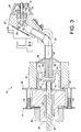
- FIG. 3 is a cross-sectional view of a nosepiece and associated fluid pump system of the non-contact tonometer shown in FIG. 1;
- FIG. 4 is an exploded perspective view of the fluid pump shown in FIG. 3;
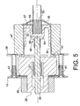
- FIG. 5 is a cross-sectional view showing a compression stroke of the fluid pump shown in FIG. 3;
- FIG. 6 is a cross-sectional view of a fluid pump formed in accordance with an alternative embodiment of the present invention.
- FIG. 7 is a cross-sectional view of a fluid pump formed in accordance with a further embodiment of the present invention.
- NCT 10 In three dimensions (X-Y-Z alignment) relative to the patient's eye.
- the patient is instructed to gaze at a target image presented along optical axis OA by a target light source 23 and a beam splitter 29 .
- the operator 8 is preferably guided in coarse alignment of NCT 10 by viewing the patient's eye through operator eyepiece 16 along an optical axis OA that coincides with test axis TA.
- a planar-planar objective lens 19 on optical axis OA cooperates with front window 18 to support fluid discharge tube 24 without blocking the operator's view of the patient's eye.
- NCT 10 may include an alignment system as taught in U.S. Pat. No. 4,881,807, wherein the operator views a video display of the eye with superimposed instructional graphics. If NCT 10 is designed as an inexpensive screening tool wherein measurement accuracy requirements can be relaxed to reduce cost, it is conceivable to have a “go/no go” alignment system that simply confirms proper alignment without providing any instructional display or graphics to the operator. An example of a “go/no go” alignment system is described in commonly owned U.S. Pat. No. 6,361,495.
- piston 32 is unattached to plunger 30 and is merely pushed by the plunger during a compression stroke.
- the axial alignment of piston 32 with cylinder 34 is in no way dependent upon the axial alignment of plunger 30 with cylinder 34 .
- this decoupled arrangement of plunger 30 and piston 32 removes the need for critical alignment between the plunger and piston, and makes it simpler to assemble components of fluid pump system 26 .
- cylinder 34 includes a flange 37 enabling the cylinder to simply be clamped to linear solenoid 28 by a solenoid plate assembly 39 and a solenoid plate 41 adjustable relative to the solenoid plate assembly by operation of threaded fasteners 43 .
- a solenoid wrap 45 and a cylinder wrap 47 of synthetic rubber, foam or other damping material are also shown in FIGS. 3 and 4. Because piston 32 is independent from plunger 30 , the piston is unrestricted by the plunger with respect to its radial degree of freedom and therefore is self-aligning relative to corresponding cylinder 34 . As a result, the fluid pump system provides a more consistent fluid pulse over time because slight alignment shifts in the mounting and position of the solenoid after a large number of cycles do not affect the axial alignment of the piston relative to the cylinder.
- Plunger 30 is characterized by an abutment end 49 that preferably includes a protective cap 50 of plastic or other suitable material to maintain substantially wear-free engagement between the plunger and piston 32 .
- solenoid return springs in commercially available solenoids are chosen to provide a very rapid return of the driven member to its initial reference position, contributing to back flow. Therefore, it may be desirable to choose piston spring 53 such that piston 32 is returned to its stroke start position more slowly than plunger 30 is returned to its initial reference position by solenoid spring 31 .
- armature 130 is a driven member that pushes against but is unattached to a piston rod 133 .
- the abutting surfaces of armature 130 and piston rod 133 may be complementary curved surfaces to accommodate the translation of rotary motion to linear motion.
- a piston 132 fixed to piston rod 133 is therefore independent from driven armature 130 with respect to its alignment relative to a corresponding cylinder 134 .
- the driven member i.e. armature 130
- the driven member need not be directly in contact with the piston, but can be arranged in contact with an intermediate member such as piston rod 133 , and that decoupling can be introduced at any point between the driven member and piston.
- FIG. 7 shows a tonometer fluid pump system 226 formed in accordance with a further embodiment of the present invention that is generally similar to the embodiment of FIG. 3.
- plunger 30 and piston 32 are linked by a push-pull coupling 211 permitting free radially directed movement of the piston independent of the plunger while providing movement of the piston in a return axial direction opposite the axial direction traveled during the compression stroke as the plunger returns to its initial reference position.
- Push-pull coupling 211 preferably includes a first U-shaped configuration 213 associated with a leading end of plunger 30 and a second U-shaped configuration 215 associated with a trailing portion of piston 32 or with a piston rod (not shown) to which piston 32 is fixed.
- the second U-shaped configuration 215 overlaps with and is inverted relative to first U-shaped configuration 213 , thereby allowing piston 32 to be independent of plunger 30 with respect to a radial degree of freedom.
- Piston spring 53 is optional in this embodiment, but is preferably used to minimize impact noise in the fluid pump system.
- plenum chamber 36 of fluid pump system 26 is provided by an axial hole through mounting member 27 and further defined by beam splitter 29 and objective lens 19 .
- fluid discharge tube 24 comprises an inlet orifice 52 and an axially extending fluid passageway 54 connecting inlet orifice 52 with outlet orifice 42 .
- FIG. 2 A preferred arrangement for optically detecting applanation of cornea C is shown schematically in FIG. 2.
- An infra-red emitter 60 is mounted on nosepiece 25 and obliquely aimed at corneal vertex V, and a photosensitive detector 62 is located on the opposite side of optical axis OA facing corneal vertex V along an oblique direction symmetrically opposite to that of applanation emitter 60 .
- a collector lens (not shown) and a pinhole diaphragm (also not shown) are positioned in front of applanation detector 62 , which is located in the focal plane of the collector lens.
- Tonometric measurement involves correlation of the pressure within plenum chamber 36 at applanation with IOP. Therefore, a pressure sensor 64 , for example a pressure transducer or the like, is located within plenum chamber 36 for generating signal information indicative of the fluid pressure within the plenum chamber. As an alternative to directly pressure measuring plenum pressure using a pressure sensor, it is possible to indirectly measure plenum pressure by driving the fluid pump system 26 ′ such that the pressure within plenum chamber 36 increases as a known function of time, and measuring the time required to achieve applanation as a correlate to IOP.
- a pressure sensor 64 for example a pressure transducer or the like
- the analog signal information from pressure sensor 64 and applanation detector 62 is filtered and converted to digital form for processing by a central processing unit (CPU) 70 .
- the plenum pressure at the time of applanation is then correlated to IOP by CPU 70 .
- IOP measurement data are reported to the operator by liquid crystal display 20 , and can be transmitted, preferably by wireless transmission, to a printing device and/or a remote computer.
Abstract
Description
- The present invention relates generally to ophthalmic instruments, and more particularly to non-contact tonometers that measure intraocular pressure (IOP) by directing a fluid pulse at an eye to transfigure the cornea.
- Non-contact tonometers are well-known in the field of ophthalmology for measuring intraocular pressure (IOP) by directing a fluid pulse at the cornea to cause observable deformation of the cornea. Most commonly, the observable deformation is a flattening of a predetermined area of the cornea, a condition known as applanation. In prior art non-contact tonometers, the fluid pulse is generated by a fluid pump system defining a plenum chamber for pressurized fluid. In order to direct the fluid pulse at the patient's cornea, a narrow cylindrical fluid discharge tube is arranged in flow communication with the plenum chamber.
- A common fluid pump system found in non-contact tonometers includes a rotary solenoid having a driven armature, a piston rod pivotally coupled to the solenoid armature, a piston fixed to the end of the piston rod for travel therewith, and a cylinder receiving the piston in close slidable fit to allow axial movement of the piston relative to the cylinder during a compression stroke. An example of this type of fluid pump system can be seen in U.S. Pat. No. 3,585,849 issued Jun. 22, 1971. In fluid pump systems of the type described, the driven armature, piston rod, and piston are connected in series, and thus the radial position of the piston in the cylinder is influenced by the driven armature and piston rod. Consequently, the solenoid, piston rod, piston and cylinder must be manufactured and located according to close tolerances to ensure that the piston moves in axial alignment with the cylinder during a compression stroke.
- In more recent non-contact tonometers, linear motors are used to drive the piston. The piston is either directly coupled to an axially driven armature of the linear motor, or is indirectly coupled to the axially driven armature by a piston rod to which the piston is fixed. Here again, the components of the fluid pump system must be manufactured and mounted in the instrument according to close tolerances to ensure axial alignment of the piston with the cylinder for providing reliable and repeatable performance.
- The necessity to design, manufacture, and assemble component parts of the fluid pump system of a non-contact tonometer pursuant to critical tolerance specifications adds to the production time and cost of the instrument. Despite time consuming and expensive efforts to provide a smooth and repeatable piston compression stroke, fluid pump systems of the prior art are accompanied by performance limitations caused by the interconnection of the various system components.
- Therefore, it is an object of the present invention to provide a non-contact tonometer with an improved fluid pump system that is easier, less costly, and faster to design and manufacture.
- It is another object of the present invention to provide a non-contact tonometer with a fluid pump system that exhibits improved performance over tonometer fluid pump systems of the prior art.
- It is a further object of the present invention to provide a non-contact tonometer with an improved fluid pump system that involves relaxed tolerances in manufacture and assembly alignment, and which avoids the need for complex universal joint couplings.
- The invention is embodied in a non-contact tonometer of a general type comprising a fluid pump system, a fluid discharge tube in communication with the fluid pump system for directing a fluid pulse at a patient's eye to cause applanation of the cornea, applanation detection means for monitoring the cornea to detect applanation caused by the fluid pulse, means for determining a fluid pressure within a plenum chamber of the fluid pump system at a moment when the cornea reaches applanation, and processing means for correlating the plenum pressure with an intraocular pressure of the patient's eye. In accordance with a preferred embodiment of the present invention, the fluid pump system comprises a linear solenoid having a driven member in the form of a plunger that moves axially when the solenoid is energized, and a piston situated adjacent an abutment end of the plunger for engagement thereby. The piston is not coupled to the plunger, but is merely pushed during a compression stroke to move axially relative to a surrounding cylinder with which the piston cooperates to define a compression chamber. A spring bearing against a front wall of the cylinder and a leading surface of the piston provides return motion to the piston. As will be appreciated, decoupling the piston from the solenoid plunger makes the axial alignment of the piston relative to the cylinder independent of the axial alignment of the plunger relative to the cylinder. In other words, the piston will remain aligned for slidable axial movement within the cylinder even if the plunger is “off center” with respect to the cylinder and/or piston. Thus, the present invention allows for relaxation of tolerances and ensures that the piston remains in axial alignment with the cylinder over time for generating a more consistent air pulse to improve measurement performance.
- The nature and mode of operation of the present invention will now be more fully described in the following detailed description of the invention taken with the accompanying drawing figures, in which:
- FIG. 1 is a perspective view of a non-contact tonometer formed in accordance with a preferred embodiment of the present invention;
- FIG. 2 is a schematic diagram of the non-contact tonometer shown in FIG. 1;
- FIG. 3 is a cross-sectional view of a nosepiece and associated fluid pump system of the non-contact tonometer shown in FIG. 1;
- FIG. 4 is an exploded perspective view of the fluid pump shown in FIG. 3;
- FIG. 5 is a cross-sectional view showing a compression stroke of the fluid pump shown in FIG. 3;
- FIG. 6 is a cross-sectional view of a fluid pump formed in accordance with an alternative embodiment of the present invention; and
- FIG. 7 is a cross-sectional view of a fluid pump formed in accordance with a further embodiment of the present invention.
- FIG. 1 of the drawings shows a non-contact tonometer (NCT) 10 embodying the present invention. NCT 10 is depicted as being a handheld instrument having a
handle portion 12 and ahead portion 14 at the top of the handle portion. While the present invention is described in the context of a handheld NCT, it can also be embodied in a table-top NCT.Handle portion 12 houses a rechargeable power source for energizing alignment and tonometric measurement systems carried byhead portion 14. Also visible in FIG. 1 is anoperator eyepiece 16 at one end ofhead portion 14, afront window 18 at an opposite end ofhead portion 14 for facing a patient, and aliquid crystal display 20 withpushbutton control overlay 22 angled toward the operator nearoperator eyepiece 16. - FIG. 2 provides a schematic representation of the alignment and tonometric measurement systems housed by
head portion 14. NCT 10 is operable to discharge a fluid pulse through afluid discharge tube 24 aligned along a test axis TA to cause observable deformation of a patient's cornea C for purposes of measuring intraocular pressure. The fluid pulse is generated by afluid pump system 26 communicating withfluid discharge tube 24, which extends through anosepiece 25 fixed to amounting member 27 seen in FIG. 3. - As a prerequisite to testing, it is necessary for an operator 8 to align
NCT 10 in three dimensions (X-Y-Z alignment) relative to the patient's eye. The patient is instructed to gaze at a target image presented along optical axis OA by atarget light source 23 and abeam splitter 29. The operator 8 is preferably guided in coarse alignment ofNCT 10 by viewing the patient's eye throughoperator eyepiece 16 along an optical axis OA that coincides with test axis TA. A planar-planarobjective lens 19 on optical axis OA cooperates withfront window 18 to supportfluid discharge tube 24 without blocking the operator's view of the patient's eye. In a preferred embodiment, an opto-electronicposition detection system 40 associated withnosepiece 25 senses the position of anoutlet orifice 42 offluid discharge tube 24 relative to a corneal vertex V and provides signal information used to drive an instructive “heads up”display 44 providing real time X, Y, and Z alignment cues. An image ofinstructive display 44 is projected to the operator along optical axis OA by abeam splitter 46, such that the instructive display image is optically superimposed with an image of the patient's eye as viewed by the operator. Proper alignment is confirmed byposition detection system 40.Reference numerals position detection system 40. Commonly owned U.S. patent application Ser. No. 09/992,875, filed Nov. 6, 2001 and incorporated herein by reference in its entirety, describes a preferred alignment system in greater detail at paragraphs [0022] through [0036] and FIGS. 3-10. - Alternative means for aligning NCT 10 are also possible. By way of non-limiting example, NCT 10 may include an alignment system as taught in U.S. Pat. No. 4,881,807, wherein the operator views a video display of the eye with superimposed instructional graphics. If NCT 10 is designed as an inexpensive screening tool wherein measurement accuracy requirements can be relaxed to reduce cost, it is conceivable to have a “go/no go” alignment system that simply confirms proper alignment without providing any instructional display or graphics to the operator. An example of a “go/no go” alignment system is described in commonly owned U.S. Pat. No. 6,361,495.
- Once proper alignment of NCT 10 is achieved,
fluid pump system 26 is triggered to generate a fluid pulse. Referring to FIGS. 3 and 4,fluid pump system 26 preferably comprises alinear solenoid 28 having aplunger 30, apiston 32 driven byplunger 30 and slidably received by acorresponding cylinder 34 to compress air within acompression chamber 35 whensolenoid 28 is energized, and aplenum chamber 36 in flow communication withcompression chamber 35 by way of afluid conduit 38.Fluid discharge tube 24 extends into and communicates withplenum chamber 36, thus enabling flow communication betweencompression chamber 35 anddischarge tube 24. - In accordance with the present invention,
piston 32 is unattached to plunger 30 and is merely pushed by the plunger during a compression stroke. As a result, the axial alignment ofpiston 32 withcylinder 34 is in no way dependent upon the axial alignment ofplunger 30 withcylinder 34. As will be appreciated, this decoupled arrangement ofplunger 30 andpiston 32 removes the need for critical alignment between the plunger and piston, and makes it simpler to assemble components offluid pump system 26. In the embodiment depicted in FIGS. 3 and 4,cylinder 34 includes aflange 37 enabling the cylinder to simply be clamped tolinear solenoid 28 by asolenoid plate assembly 39 and asolenoid plate 41 adjustable relative to the solenoid plate assembly by operation of threadedfasteners 43. Asolenoid wrap 45 and acylinder wrap 47 of synthetic rubber, foam or other damping material are also shown in FIGS. 3 and 4. Becausepiston 32 is independent fromplunger 30, the piston is unrestricted by the plunger with respect to its radial degree of freedom and therefore is self-aligning relative to correspondingcylinder 34. As a result, the fluid pump system provides a more consistent fluid pulse over time because slight alignment shifts in the mounting and position of the solenoid after a large number of cycles do not affect the axial alignment of the piston relative to the cylinder. -
Plunger 30 is characterized by anabutment end 49 that preferably includes aprotective cap 50 of plastic or other suitable material to maintain substantially wear-free engagement between the plunger andpiston 32. -
Solenoid 28 preferably includes a means for returningplunger 30 to an initial reference position as illustrated in FIG. 3. Commonly, the return means is aspring 31 acting on the plunger. Becausepiston 32 is not attached toplunger 30, aspring 53 is provided to act betweencylinder 34 andpiston 32 to return the piston to its stroke start position illustrated in FIG. 3. In a preferred assembly,spring 53 is a coil spring that bears against afront wall 55 ofcylinder 34 and a leadingsurface 57 ofpiston 32, and is arranged to be coaxial with the piston and cylinder. Arecess 59 provided inpiston leading surface 57 receives an end ofspring 53 to help locate and hold the spring in place. - FIG. 5 shows
fluid pump system 26 during a compression stroke. Whensolenoid 28 is energized,plunger 30 is forced from its initial reference position to the left in FIG. 5, pushingpiston 32 from its stroke start position intocylinder 34 to compress fluid withincompression chamber 35. This action loadssolenoid spring 31 andpiston spring 53 in compression so that whensolenoid 28 is de-energized,solenoid spring 31 forces plunger 30 to return to its initial reference position andpiston spring 53forces piston 32 back to its stroke start position.Piston spring 53 may be selected with a suitable spring constant for returningpiston 32 to its stroke start position in a relatively slow manner to reduce back flow of external air into the discharge tube. By contrast, in prior art non-contact tonometers wherein the piston and driven member are coupled together, return of the piston is governed by the solenoid return spring and cannot be independently controlled. Typically, solenoid return springs, in commercially available solenoids are chosen to provide a very rapid return of the driven member to its initial reference position, contributing to back flow. Therefore, it may be desirable to choosepiston spring 53 such thatpiston 32 is returned to its stroke start position more slowly thanplunger 30 is returned to its initial reference position bysolenoid spring 31. - As will be understood from FIG. 6, the principle of the present invention can be applied to a tonometer
fluid pump system 126 employing arotary solenoid 128 that pivots anarmature 130 counterclockwise as seen in FIG. 6 in response to energizing current. In the embodiment of FIG. 6,armature 130 is a driven member that pushes against but is unattached to apiston rod 133. The abutting surfaces ofarmature 130 andpiston rod 133 may be complementary curved surfaces to accommodate the translation of rotary motion to linear motion. Apiston 132 fixed topiston rod 133 is therefore independent from drivenarmature 130 with respect to its alignment relative to acorresponding cylinder 134. This embodiment further illustrates that the driven member (i.e. armature 130) need not be directly in contact with the piston, but can be arranged in contact with an intermediate member such aspiston rod 133, and that decoupling can be introduced at any point between the driven member and piston. - FIG. 7 shows a tonometer
fluid pump system 226 formed in accordance with a further embodiment of the present invention that is generally similar to the embodiment of FIG. 3. However, in the embodiment of FIG. 7,plunger 30 andpiston 32 are linked by a push-pull coupling 211 permitting free radially directed movement of the piston independent of the plunger while providing movement of the piston in a return axial direction opposite the axial direction traveled during the compression stroke as the plunger returns to its initial reference position. Push-pull coupling 211 preferably includes a firstU-shaped configuration 213 associated with a leading end ofplunger 30 and a secondU-shaped configuration 215 associated with a trailing portion ofpiston 32 or with a piston rod (not shown) to whichpiston 32 is fixed. The secondU-shaped configuration 215 overlaps with and is inverted relative to firstU-shaped configuration 213, thereby allowingpiston 32 to be independent ofplunger 30 with respect to a radial degree of freedom.Piston spring 53 is optional in this embodiment, but is preferably used to minimize impact noise in the fluid pump system. - Referring again to FIG. 3, it will be seen that
plenum chamber 36 offluid pump system 26 is provided by an axial hole through mountingmember 27 and further defined bybeam splitter 29 andobjective lens 19. In addition, it will be seen thatfluid discharge tube 24 comprises aninlet orifice 52 and an axially extendingfluid passageway 54 connectinginlet orifice 52 withoutlet orifice 42. - A preferred arrangement for optically detecting applanation of cornea C is shown schematically in FIG. 2. An infra-
red emitter 60 is mounted onnosepiece 25 and obliquely aimed at corneal vertex V, and aphotosensitive detector 62 is located on the opposite side of optical axis OA facing corneal vertex V along an oblique direction symmetrically opposite to that ofapplanation emitter 60. A collector lens (not shown) and a pinhole diaphragm (also not shown) are positioned in front ofapplanation detector 62, which is located in the focal plane of the collector lens. When the cornea C is in its normal convex shape, parallel incident rays fromemitter 60 are reflected in a fanned-out fashion by the curved corneal surface, and a weak detection signal is generated atapplanation detector 62. As a portion of the corneal surface approximates a flat surface at applanation, the incident parallel beam is reflected by the flat surface as a parallel beam in the direction of the collector lens, which focuses the beam through the pinhole diaphragm and onto the surface ofapplanation detector 62. As a result,applanation detector 62 registers a peak detection signal corresponding to applanation. Those familiar with non-contact tonometers will recognize that this arrangement for optically detecting applanation is already known from the prior art. - Tonometric measurement involves correlation of the pressure within
plenum chamber 36 at applanation with IOP. Therefore, apressure sensor 64, for example a pressure transducer or the like, is located withinplenum chamber 36 for generating signal information indicative of the fluid pressure within the plenum chamber. As an alternative to directly pressure measuring plenum pressure using a pressure sensor, it is possible to indirectly measure plenum pressure by driving thefluid pump system 26′ such that the pressure withinplenum chamber 36 increases as a known function of time, and measuring the time required to achieve applanation as a correlate to IOP. - The analog signal information from
pressure sensor 64 andapplanation detector 62 is filtered and converted to digital form for processing by a central processing unit (CPU) 70. The plenum pressure at the time of applanation is then correlated to IOP byCPU 70. IOP measurement data are reported to the operator byliquid crystal display 20, and can be transmitted, preferably by wireless transmission, to a printing device and/or a remote computer.
Claims (29)
Priority Applications (1)
| Application Number | Priority Date | Filing Date | Title |
|---|---|---|---|
| US10/117,510 US6726625B2 (en) | 2002-04-05 | 2002-04-05 | Non-contact tonometer having improved air pump |
Applications Claiming Priority (1)
| Application Number | Priority Date | Filing Date | Title |
|---|---|---|---|
| US10/117,510 US6726625B2 (en) | 2002-04-05 | 2002-04-05 | Non-contact tonometer having improved air pump |
Publications (2)
| Publication Number | Publication Date |
|---|---|
| US20030191381A1 true US20030191381A1 (en) | 2003-10-09 |
| US6726625B2 US6726625B2 (en) | 2004-04-27 |
Family
ID=28674220
Family Applications (1)
| Application Number | Title | Priority Date | Filing Date |
|---|---|---|---|
| US10/117,510 Expired - Fee Related US6726625B2 (en) | 2002-04-05 | 2002-04-05 | Non-contact tonometer having improved air pump |
Country Status (1)
| Country | Link |
|---|---|
| US (1) | US6726625B2 (en) |
Cited By (4)
| Publication number | Priority date | Publication date | Assignee | Title |
|---|---|---|---|---|
| US20110057811A1 (en) * | 2009-09-08 | 2011-03-10 | Rosemount Inc. | Projected instrument displays for field mounted process instruments |
| US8540746B2 (en) | 1998-08-20 | 2013-09-24 | Zimmer Spine, Inc. | Cannula for receiving surgical instruments |
| US8777997B2 (en) | 2000-08-01 | 2014-07-15 | Zimmer Spine, Inc. | Method for securing vertebrae |
| US20210022608A1 (en) * | 2018-03-12 | 2021-01-28 | Ioppreceyese Ltd. | Non-Contact Home-Tonometry System for Measuring Intraocular Pressure |
Families Citing this family (6)
| Publication number | Priority date | Publication date | Assignee | Title |
|---|---|---|---|---|
| CA2803828C (en) * | 2005-03-31 | 2015-11-24 | Alcon, Inc. | Footswitch operable to control a surgical system |
| US8465473B2 (en) * | 2007-03-28 | 2013-06-18 | Novartis Ag | Surgical footswitch with movable shroud |
| US7981109B2 (en) | 2007-08-15 | 2011-07-19 | Novartis Ag | System and method for a user interface |
| CA2724127A1 (en) * | 2008-06-05 | 2009-12-10 | Alcon Research, Ltd. | Wireless network and methods of wireless communication for ophthalmic surgical consoles |
| TWI522085B (en) | 2010-04-14 | 2016-02-21 | 愛爾康研究有限公司 | Display for ophthalmic surgical console with user-selectable sectors |
| US8613704B2 (en) * | 2011-01-25 | 2013-12-24 | Reichert, Inc. | Subsystems and methods for non-contact corneal deformation |
Citations (5)
| Publication number | Priority date | Publication date | Assignee | Title |
|---|---|---|---|---|
| US4947849A (en) * | 1984-06-12 | 1990-08-14 | Tokyo Kogaku Kikai Kabushiki Kaisha | Non-contact type tonometer |
| US4996990A (en) * | 1987-08-12 | 1991-03-05 | Tokyo Kogaku Kikai Kabushiki Kaisha | Air-puff tonometer |
| US5048526A (en) * | 1987-08-20 | 1991-09-17 | Kabushiki Kaisha Topcon | Gas jet shooting device for use with a non-contact tonometer |
| US5301598A (en) * | 1990-12-06 | 1994-04-12 | Sms Schloemann-Siemag Aktiengesellschaft | Piston-cylinder unit for producing and transmitting compressive forces |
| US5957381A (en) * | 1996-10-09 | 1999-09-28 | Zexel Corporation | Fuel injection nozzle |
Family Cites Families (1)
| Publication number | Priority date | Publication date | Assignee | Title |
|---|---|---|---|---|
| US3585849A (en) | 1968-10-09 | 1971-06-22 | American Optical Corp | Method and apparatus for measuring intraocular pressure |
-
2002
- 2002-04-05 US US10/117,510 patent/US6726625B2/en not_active Expired - Fee Related
Patent Citations (5)
| Publication number | Priority date | Publication date | Assignee | Title |
|---|---|---|---|---|
| US4947849A (en) * | 1984-06-12 | 1990-08-14 | Tokyo Kogaku Kikai Kabushiki Kaisha | Non-contact type tonometer |
| US4996990A (en) * | 1987-08-12 | 1991-03-05 | Tokyo Kogaku Kikai Kabushiki Kaisha | Air-puff tonometer |
| US5048526A (en) * | 1987-08-20 | 1991-09-17 | Kabushiki Kaisha Topcon | Gas jet shooting device for use with a non-contact tonometer |
| US5301598A (en) * | 1990-12-06 | 1994-04-12 | Sms Schloemann-Siemag Aktiengesellschaft | Piston-cylinder unit for producing and transmitting compressive forces |
| US5957381A (en) * | 1996-10-09 | 1999-09-28 | Zexel Corporation | Fuel injection nozzle |
Cited By (7)
| Publication number | Priority date | Publication date | Assignee | Title |
|---|---|---|---|---|
| US8540746B2 (en) | 1998-08-20 | 2013-09-24 | Zimmer Spine, Inc. | Cannula for receiving surgical instruments |
| US8777997B2 (en) | 2000-08-01 | 2014-07-15 | Zimmer Spine, Inc. | Method for securing vertebrae |
| US8864785B2 (en) | 2000-08-01 | 2014-10-21 | Zimmer Spine, Inc. | Method for securing vertebrae |
| US9622735B2 (en) | 2000-08-01 | 2017-04-18 | Zimmer Spine, Inc. | Method for securing vertebrae |
| US20110057811A1 (en) * | 2009-09-08 | 2011-03-10 | Rosemount Inc. | Projected instrument displays for field mounted process instruments |
| US8299938B2 (en) | 2009-09-08 | 2012-10-30 | Rosemount Inc. | Projected instrument displays for field mounted process instruments |
| US20210022608A1 (en) * | 2018-03-12 | 2021-01-28 | Ioppreceyese Ltd. | Non-Contact Home-Tonometry System for Measuring Intraocular Pressure |
Also Published As
| Publication number | Publication date |
|---|---|
| US6726625B2 (en) | 2004-04-27 |
Similar Documents
| Publication | Publication Date | Title |
|---|---|---|
| US7515321B2 (en) | Ophthalmic apparatus | |
| US6726625B2 (en) | Non-contact tonometer having improved air pump | |
| KR100647431B1 (en) | Hand-held non-contact tonometer | |
| EP1419729B1 (en) | Alignment guidance system | |
| TWI407946B (en) | System for ophthalmic laser surgery | |
| US5299573A (en) | Tonometer | |
| US6537215B2 (en) | Non-contact type tonometer | |
| US9289124B2 (en) | Tonometer calibration tool | |
| US5680196A (en) | Position detecting apparatus for an ophthalmologic apparatus | |
| JP3330461B2 (en) | Non-contact tonometer | |
| US20030191382A1 (en) | Non-contact tonometer | |
| US20030088170A1 (en) | Non-contact tonometer having mechanically isolated cylinder | |
| JPH08280630A (en) | Eye closing type tonometry method and apparatus | |
| US5989195A (en) | Noncontact tonometer | |
| JPH06327633A (en) | Ophthalmological equipment | |
| JP2681135B2 (en) | Ophthalmic diagnostic equipment | |
| EP4046567A1 (en) | System for non-contact measuring intraocular pressure of an eye | |
| JPH0556932A (en) | Tonometer | |
| JPH0759736A (en) | Ophthalmologic apparatus | |
| JPH0360263B2 (en) | ||
| JP2003199714A (en) | Non-contact type tonometer | |
| JPH05253189A (en) | Ophthalmotonometer | |
| JPH0360490B2 (en) | ||
| JPS6397140A (en) | Tonometer | |
| JPH11216118A (en) | Non-contact type tonometer |
Legal Events
| Date | Code | Title | Description |
|---|---|---|---|
| AS | Assignment |
Owner name: LEICA MICROSYSTEMS INC., NEW YORK Free format text: ASSIGNMENT OF ASSIGNORS INTEREST;ASSIGNOR:LUCE, DAVID A.;REEL/FRAME:012777/0205 Effective date: 20020404 |
|
| AS | Assignment |
Owner name: REICHERT, INC., NEW YORK Free format text: ASSIGNMENT OF ASSIGNORS INTEREST;ASSIGNOR:LEICA MICROSYSTEMS INC.;REEL/FRAME:013787/0880 Effective date: 20030128 |
|
| AS | Assignment |
Owner name: MANUFACTURERS AND TRADERS TRUST COMPANY, NEW YORK Free format text: SECURITY AGREEMENT;ASSIGNOR:REICHERT, INC.;REEL/FRAME:017006/0751 Effective date: 20060104 |
|
| FEPP | Fee payment procedure |
Free format text: PAT HOLDER CLAIMS SMALL ENTITY STATUS, ENTITY STATUS SET TO SMALL (ORIGINAL EVENT CODE: LTOS); ENTITY STATUS OF PATENT OWNER: SMALL ENTITY |
|
| AS | Assignment |
Owner name: CHARTER ONE BANK, N.A., ILLINOIS Free format text: SECURITY AGREEMENT;ASSIGNOR:REICHERT, INC.;REEL/FRAME:018961/0844 Effective date: 20070110 |
|
| FPAY | Fee payment |
Year of fee payment: 4 |
|
| FPAY | Fee payment |
Year of fee payment: 8 |
|
| AS | Assignment |
Owner name: REICHERT, INC., NEW YORK Free format text: RELEASE OF SECURITY INTEREST IN PATENTS;ASSIGNOR:MANUFACTURERS AND TRADERS TRUST COMPANY;REEL/FRAME:027046/0356 Effective date: 20111007 |
|
| AS | Assignment |
Owner name: REICHERT INC., NEW YORK Free format text: RELEASE OF SECURITY INTEREST IN PATENTS;ASSIGNOR:RBS CITIZENS, N.A. D/B/A CHARTER ONE BANK, N.A.;REEL/FRAME:027074/0918 Effective date: 20111014 |
|
| REMI | Maintenance fee reminder mailed | ||
| LAPS | Lapse for failure to pay maintenance fees | ||
| STCH | Information on status: patent discontinuation |
Free format text: PATENT EXPIRED DUE TO NONPAYMENT OF MAINTENANCE FEES UNDER 37 CFR 1.362 |
|
| FP | Lapsed due to failure to pay maintenance fee |
Effective date: 20160427 |