US20030191369A1 - Omnidirectional endoscope apparatus - Google Patents
Omnidirectional endoscope apparatus Download PDFInfo
- Publication number
- US20030191369A1 US20030191369A1 US10/393,231 US39323103A US2003191369A1 US 20030191369 A1 US20030191369 A1 US 20030191369A1 US 39323103 A US39323103 A US 39323103A US 2003191369 A1 US2003191369 A1 US 2003191369A1
- Authority
- US
- United States
- Prior art keywords
- light
- omnidirectional
- illumination light
- distal end
- insertion section
- Prior art date
- Legal status (The legal status is an assumption and is not a legal conclusion. Google has not performed a legal analysis and makes no representation as to the accuracy of the status listed.)
- Granted
Links
Images


Classifications
-
- A—HUMAN NECESSITIES
- A61—MEDICAL OR VETERINARY SCIENCE; HYGIENE
- A61B—DIAGNOSIS; SURGERY; IDENTIFICATION
- A61B1/00—Instruments for performing medical examinations of the interior of cavities or tubes of the body by visual or photographical inspection, e.g. endoscopes; Illuminating arrangements therefor
- A61B1/04—Instruments for performing medical examinations of the interior of cavities or tubes of the body by visual or photographical inspection, e.g. endoscopes; Illuminating arrangements therefor combined with photographic or television appliances
-
- A—HUMAN NECESSITIES
- A61—MEDICAL OR VETERINARY SCIENCE; HYGIENE
- A61B—DIAGNOSIS; SURGERY; IDENTIFICATION
- A61B1/00—Instruments for performing medical examinations of the interior of cavities or tubes of the body by visual or photographical inspection, e.g. endoscopes; Illuminating arrangements therefor
- A61B1/00064—Constructional details of the endoscope body
- A61B1/00071—Insertion part of the endoscope body
- A61B1/0008—Insertion part of the endoscope body characterised by distal tip features
- A61B1/00096—Optical elements
-
- A—HUMAN NECESSITIES
- A61—MEDICAL OR VETERINARY SCIENCE; HYGIENE
- A61B—DIAGNOSIS; SURGERY; IDENTIFICATION
- A61B1/00—Instruments for performing medical examinations of the interior of cavities or tubes of the body by visual or photographical inspection, e.g. endoscopes; Illuminating arrangements therefor
- A61B1/00064—Constructional details of the endoscope body
- A61B1/00071—Insertion part of the endoscope body
- A61B1/0008—Insertion part of the endoscope body characterised by distal tip features
- A61B1/00101—Insertion part of the endoscope body characterised by distal tip features the distal tip features being detachable
-
- A—HUMAN NECESSITIES
- A61—MEDICAL OR VETERINARY SCIENCE; HYGIENE
- A61B—DIAGNOSIS; SURGERY; IDENTIFICATION
- A61B1/00—Instruments for performing medical examinations of the interior of cavities or tubes of the body by visual or photographical inspection, e.g. endoscopes; Illuminating arrangements therefor
- A61B1/00163—Optical arrangements
- A61B1/00174—Optical arrangements characterised by the viewing angles
-
- A—HUMAN NECESSITIES
- A61—MEDICAL OR VETERINARY SCIENCE; HYGIENE
- A61B—DIAGNOSIS; SURGERY; IDENTIFICATION
- A61B1/00—Instruments for performing medical examinations of the interior of cavities or tubes of the body by visual or photographical inspection, e.g. endoscopes; Illuminating arrangements therefor
- A61B1/00163—Optical arrangements
- A61B1/00193—Optical arrangements adapted for stereoscopic vision
-
- A—HUMAN NECESSITIES
- A61—MEDICAL OR VETERINARY SCIENCE; HYGIENE
- A61B—DIAGNOSIS; SURGERY; IDENTIFICATION
- A61B1/00—Instruments for performing medical examinations of the interior of cavities or tubes of the body by visual or photographical inspection, e.g. endoscopes; Illuminating arrangements therefor
- A61B1/06—Instruments for performing medical examinations of the interior of cavities or tubes of the body by visual or photographical inspection, e.g. endoscopes; Illuminating arrangements therefor with illuminating arrangements
- A61B1/07—Instruments for performing medical examinations of the interior of cavities or tubes of the body by visual or photographical inspection, e.g. endoscopes; Illuminating arrangements therefor with illuminating arrangements using light-conductive means, e.g. optical fibres
Definitions
- the present invention relates to an omnidirectional endoscope apparatus having a viewfield covering all around the periphery in the peripheral direction.
- An endoscope is effective as an apparatus for observing the inner periphery of a narrow and/or elongated space such as the inside of a cylinder block of an engine and the inside of piping, for example.
- a typical endoscope has a limited view field angle, such operation as to turn the endoscope is required for the user in order to observe all around the periphery.
- an omnidirectional endoscope which can receive an incident light from all around the periphery in the peripheral direction and take it into image transmitting means is effective because the user can see all around the periphery at a time.
- the present invention provides an omnidirectional endoscope having a view field covering all around the periphery in the peripheral direction, comprising a main body section, an insertion section extending from the main body section, an omnidirectional light receiving mechanism disposed at a distal end part of the insertion section and for receiving an incident light coming from all around the periphery in the peripheral direction and reflecting it towards a basal end, image transmitting means received in the main body section and the insertion section and for transmitting light coming from the omnidirectional light receiving mechanism, and an illumination light transmitting mechanism.
- the illumination light transmitting mechanism includes illumination light transmitting means, a retaining part and a slide control part. The illumination light transmitting means extends along the insertion section.
- the retaining part Owing to the above arrangement, it can be operated such that when the inside space of an object to be observed is small, the retaining part is slid towards the distal end in order to bring the outgoing position of the illumination light toward the omnidirectional light receiving mechanism and when the inside space of the object is large, the retaining part is slid toward the basal end in order to bring the outgoing position of the illumination light away from the omnidirectional light receiving mechanism.
- the illumination light can strike upon the view field of the omnidirectional light receiving mechanism.
- a clear and bright image can be obtained.
- the omnidirectional light receiving mechanism includes a transparent cylindrical observing window, a convex mirror received in the observing window and for reflecting an incident light coming from the observing window toward the basal end and thus toward the image transmitting means, and a rod-like body disposed at a top part of the convex mirror in such a manner as to project toward the basal end, the rod-like body being adapted to absorb the light passing across the inside space of the observing window which light would otherwise be reflected on the inner peripheral surface of the observing window and proceed toward the convex mirror.
- the observing window extends toward the distal end beyond the convex mirror, and a ring-like light absorbing member is disposed at an outer periphery of the extending part of the observing window.
- the omnidirectional light receiving mechanism is removably attached to the insertion section.
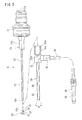
- FIG. 1 is a side view of an omnidirectional endoscope apparatus according to one embodiment of the present invention.
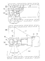
- FIG. 4( a ) is a sectional view, like FIG. 3, showing the ways of observing the inner peripheral surface of a reduced-diameter tube through the omnidirectional endoscope apparatus.
- FIG. 4( b ) is a sectional view, like FIG. 3, showing the ways of observing the inner peripheral surface of an enlarged-diameter tube through the omnidirectional endoscope apparatus.
- FIGS. 1 and 2 show an omnidirectional endoscope apparatus 1 .
- the omnidirectional endoscope apparatus 1 comprises an endoscope 10 , an omnidirectional light receiving unit 20 (omnidirectional light receiving mechanism), and an illumination light transmitting unit 30 (illumination light transmitting mechanism).
- Those component elements 10 , 20 , 30 are removably united together.
- the endoscope 10 includes a main body section 11 having an eyepiece part 11 a, and a metal-made insertion section 12 extending linearly along an axis LO from a tip shaft 11 b of the main body section 11 .
- the material of the insertion section 12 is not limited to hard metal but it may be flexible material such as resin.
- a relay lens optical system 13 (image transmission means) is received in the main body section 11 and insertion section 12 .
- the basal end of the relay lens optical system 13 is optically connected to the eyepiece 11 a .
- the tip part of the relay optical system 13 is optically connected to an objective optical system (not shown) and thus to the omnidirectional light receiving unit 20 which objective optical system is received in the tip part of the insertion section 12 .
- an image guide composed of a bundle of plural optical fibers may be used as the image transmission means.
- the circular cylindrical observing window 22 is subjected to the purpose for retaining the light receiving optical member 23 .
- the light receiving optical member 23 is received in the circular cylindrical observing window 22 .
- the tip opening of the circular cylindrical observing window 22 is blocked with a cap 25 .
- the light receiving member 23 is fixed to this cap 25 .
- the light receiving member 23 is made of metal, glass, resin or the like.
- the light receiving member 23 integrally includes a basal part 23 c , a convex mirror 23 a , and a rod-like body 23 b .
- the basal part 23 c has a circular columnar configuration coaxial with the window 22 and thus the insertion section 12 and fitted to a fitting recess 25 a of the cap 25 .
- the convex mirror 23 a is formed on a basal end face of the basal part 23 b .
- the convex mirror 23 a has a viewfield spreading sideways in the form of a sector on a plane along the axis LO. This viewfield is spread so wide as 360 degrees around the axis LO.
- the convex mirror 23 a is provided at its apex with the above-mentioned rod-like body 23 b which projects toward the basal end.
- the rod-like body 23 b has an elongated conical configuration (rod-like or needle-like configuration) along the axis LO of the window 22 and thus, along the insertion section 12 . Matt/black color treatment for absorbing light is applied to the surface of the rod-like body 23 b.
- the cylindrical observing window 22 is extended towards the tip beyond the boundary between the convex mirror 23 a and basal part 23 c of the light receiving member 23 .
- a light absorbing ring 27 (light absorbing member) is fitted to the outer peripheral surface of the extension part of the observing window 22 in such a manner as not to intervene the viewfield of the convex mirror 23 a .
- the light absorbing ring 27 is also fitted to the outer peripheral surface of the cap 25 .
- a black color film for absorbing light is applied to the entire surface (outer peripheral surface, chamfering part, end faces and inner peripheral surface) of the light absorbing ring 27 .
- the cable 32 is provided at its distal end with a light guide plug 34 .
- This plug 34 is connected to a light source (not shown) of illumination light.
- the retaining cylinder 33 has a dual structure composed of an outer tube 33 a and an inner tube 33 b which are made of thin metal.
- the material of tubes 33 a , 33 b is not limited to hard metal. Instead, the tubes 33 a , 33 b may be made of flexible material such as resin.
- a light guide 35 (illumination light transmission means) composed of a bundle of plural optical fibers is received in the plug 34 , the cable 32 , the distal end side of the grip 31 and the retaining cylinder 33 .
- the light guide 35 is in the shape of a circle in section at the insides of the plug 34 and cable 32 and is spread in the form of a hollow circle in section at the distal end side of the grip 31 toward the retaining cylinder 33 .
- the light guide 35 is embedded in the retaining cylinder 33 in such a manner as to be sandwiched between the outer tube 33 a and the inner tube 33 b.
- the distal end face of the light guide 35 is exposed to the distal end face of the retaining cylinder 33 .
- the illumination light coming from the light source is, as shown in FIG. 2 traveled along the light guide 35 and radially outputted obliquely forward (toward the distal end) from the distal end face of the light guide 35 , at an outgoing angle ⁇ which is established in accordance with the numerical aperture NA of the light guide 35 .
- a protective cover glass may be mounted on the distal end face of the light guide 35 .
- the grip 31 and the retaining cylinder 33 can also rotate about the axis LO of the endoscope 10 .
- the illumination light transmitting unit 30 can further be slid toward the distal end so as to be removed from the endoscope 10 .
- the endoscope 10 is inserted into the illumination light transmitting unit 30 first and thereafter, the omnidirectional light receiving unit 20 is attached to the endoscope 10 .
- FIG. 4( a ) shows the ways of observing a reduced-diameter tube 40 A having a comparatively small diameter.
- the device 1 is inserted into the reduced-diameter tube 40 A first with the omnidirectional light receiving unit 20 and then the insertion section 12 and retaining cylinder 33 . Since the object is small in diameter, the grip 31 at hand is then slid toward the distal end (toward the inside of the reduced-diameter tube 40 A) with respect to the endoscope main body section 11 and thus, the retaining cylinder 33 is brought toward the omnidirectional light receiving unit 20 .
- the light guide 35 and the distal end face of the retaining cylinder 33 are located such that a center line direction Lc of the view field of the convex mirror 23 a in a plane along the axis LO is intersected with an outgoing angle direction L ⁇ of the light guide 35 almost at the inner peripheral surface of the reduced-diameter tube 40 A.
- an illumination light L 1 coming from the distal end face of the light guide 35 can strike upon the entire area of that part of the inner peripheral surface of the tube 40 which entire area corresponds to the view field of the convex mirror 23 a , and therefore, the illumination light L 1 can illuminate the entire view field.
- the image light L 2 is made incident into the cylindrical observing window 22 from the directions of 360 degrees around the side periphery and this image light L 2 coming from the directions of 360 degrees is reflected toward the insertion section 12 by the convex mirror 23 a . Accordingly, an image all around the periphery of the inner peripheral surface can be observed at a time. By this, observing efficiency can be enhanced.
- FIG. 4( b ) shows the ways of observing an enlarged-diameter tube 40 B having a comparatively large diameter.
- the grip 21 is slid toward the basal end with respect to the endoscope main body section 11 and thus, the retaining cylinder 33 is brought away from the omnidirectional light receiving unit 20 .
- the reduced-diameter tube 40 A it can be arranged such that a center line direction Lc of the view field of the convex mirror 23 a is intersected with an outgoing angle direction L ⁇ of the light guide 35 almost at the inner peripheral surface of the enlarged-diameter tube 40 B.
- the illumination light L 1 obliquely strikes the inner peripheral surfaces of the tubes 40 A, 40 B, irregularities, such as cuts or scratches formed, if any, on the inner peripheral surface appear in the form of a shade and so, they can easily be discovered.
- irregularities such as cuts or scratches formed, if any, on the inner peripheral surface appear in the form of a shade and so, they can easily be discovered.
- the grip 31 of the illumination light transmitting unit 30 is slightly moved back and forth with the endoscope 10 positionally fixed with respect to the tubes 40 A, 40 B, inclination of the illumination light L 1 varies and the above-mentioned shade moves. Therefore, irregularities such as cuts or scratches can more easily be discovered, and inspection efficiency can be enhanced.
- the light L 3 strikes upon the rod-like body 23 b during the time it passes across the inside space of the observing window 22 .
- the light L 2 can be absorbed before it strikes upon the inner peripheral surface of the window 22 and thus, the convex mirror 23 a . This serves to prevent the clarity of the image from being degraded and prevent the image on the opposite side from being formed.
- the light shielding ring 26 projects radially from the outer peripheral surface of the window 22 , it can also prevent the illumination light, which is generally parallel to the axis LO but slightly inclined inward, from being made incident directly into the observing window 22 . Furthermore, even if refraction directing inward occurs at the outer peripheral surface of the light shielding ring 26 , such light can be prevented from being made incident into the observing window 22 . By this, the contrast of the image can surely be prevented from being lowered.
- Two rings 26 , 27 undertake the role for protecting the observing window 22 in addition to the above-mentioned various functions.
- the omnidirectional light receiving unit 20 is removably attached to the insertion section 12 , it can easily be replaced with a new omnidirectional light receiving unit 20 or an omnidirectional light receiving mechanism having different specifications.
- the illumination light transmitting means of the illumination transmitting mechanism is good enough only if at least the distal end part is in the form of a ring capable of surrounding the insertion section of the endoscope.
- the retaining part is good enough only if it retains the illumination transmitting means at least a distal end part of which is in the form of a ring. It is accepted that the retaining part disposed at the distal end part of the insertion section and the slide control part disposed at the insertion section or main body section are connected to each other through a connecting member disposed at the insertion section. It is also accepted that the retaining part is caused to slide along the insertion section by a mechanical or electrical slide mechanism, and the slide control part controls the slide mechanism.
- the distal ends of the retaining part and illumination light transmitting means may be slanted.
- the basal end part of the retaining part may also serve as the slide control part.
- the halation preventing light absorbing member disposed at the extending part of the distal end of the cylindrical observing window is not limited to a thick member such as the light absorbing ring 27 but it may be a thin light absorbing film-like member.
- the mechanism for attaching/removing the insertion section and the omnidirectional light receiving mechanism is not limited to the screws 12 a , 21 a but it may take a wide variety of forms.
Abstract
An omnidirectional endoscope device 1 is provided at a distal end part of an insertion section 12 of an endoscope 10 with an omnidirectional light receiving unit 20 for receiving an incident light from all around the periphery in the peripheral direction and reflecting the light toward a relay lens optical system 13. The insertion section 12 slidably pierces through a retaining cylinder 33. A light guide 35 (illumination light transmitting means) is embedded in the retaining cylinder 33, and an outgoing surface at the distal end of this light guide 35 is faced with a distal end face of the retaining cylinder 33. The retaining cylinder 33 can be operated in a sliding manner by a grip 31 disposed at the basal end. By this, the illumination light can strike upon the view field of the omnidirectional light receiving mechanism regardless whether the inside space of an image to be observed is large or small.
Description
- The present invention relates to an omnidirectional endoscope apparatus having a viewfield covering all around the periphery in the peripheral direction.
- An endoscope is effective as an apparatus for observing the inner periphery of a narrow and/or elongated space such as the inside of a cylinder block of an engine and the inside of piping, for example. On the other hand, since a typical endoscope has a limited view field angle, such operation as to turn the endoscope is required for the user in order to observe all around the periphery. In this respect, an omnidirectional endoscope which can receive an incident light from all around the periphery in the peripheral direction and take it into image transmitting means is effective because the user can see all around the periphery at a time. As one example of such an omnidirectional endoscope, an endoscope is known which is equipped with, for example, a conical prism placed at a distal end of its insertion section. A distal end face of a light guide (illumination light transmitting means) occupies a position slightly on the basal end side of the conical prism. An illumination light is radially emitted obliquely forward from this distal end face and illuminates an object to be observed. (See the Japanese Patent Application Unexamined (Laid-Open) Publication No. H10-318727.)
- In the above known omnidirectional endoscope, the light guide is fixedly embedded in the insertion section. Accordingly, the positional relation between the distal end face of the light guide and the conical prism is held constant. For this reason, it has such a problem that an image looks dark because when the inside diameter of a space of the object to be observed is small, the illumination light strikes upon the inner peripheral surface of the space more on the basal end side than the view field region, and when the inside diameter of the space is large, the illumination light strikes upon the inner peripheral surface of the space more on the distal end side than the view field region.
- In order to solve the above problem, the present invention provides an omnidirectional endoscope having a view field covering all around the periphery in the peripheral direction, comprising a main body section, an insertion section extending from the main body section, an omnidirectional light receiving mechanism disposed at a distal end part of the insertion section and for receiving an incident light coming from all around the periphery in the peripheral direction and reflecting it towards a basal end, image transmitting means received in the main body section and the insertion section and for transmitting light coming from the omnidirectional light receiving mechanism, and an illumination light transmitting mechanism. The illumination light transmitting mechanism includes illumination light transmitting means, a retaining part and a slide control part. The illumination light transmitting means extends along the insertion section. This illumination light transmitting means transmits an illumination light and output it from the distal end face of the illumination light transmitting means. The retaining part is slidably fitted to the outer periphery of the insertion section. The retaining part retains the illumination light transmitting means, at least a distal end of which is in the form of a ring. The slide control part is disposed at the basal end of the insertion section or at the main body section. Moreover, the slide control part is connected to the retaining part. By this slide control part, the retaining part can be slid along the insertion section and thus, the distal end part of the illumination light transmitting means can be slid along the insertion section.
- Owing to the above arrangement, it can be operated such that when the inside space of an object to be observed is small, the retaining part is slid towards the distal end in order to bring the outgoing position of the illumination light toward the omnidirectional light receiving mechanism and when the inside space of the object is large, the retaining part is slid toward the basal end in order to bring the outgoing position of the illumination light away from the omnidirectional light receiving mechanism. By doing so, the illumination light can strike upon the view field of the omnidirectional light receiving mechanism. Thus, a clear and bright image can be obtained.
- Preferably, the retaining part is in the form of a cylinder for allowing almost the entire insertion section to slidably pierce therethrough, the illumination light transmitting means is embedded in the retaining part over its entire length, a ring-like distal end face of the illumination light transmitting means is faced with the distal end face of the retaining part, the slide control part is in the form of a cylinder for allowing the basal end part of the insertion section or the main body section to slidably pierce therethrough and connected to the basal end part of the retaining part, and the illumination light transmitting mechanism is separatable from the main body section and the insertion section.
- Owing to the above arrangement, the illumination light transmitting mechanism can be simplified in structure and can be replaced easily.
- Preferably, the omnidirectional light receiving mechanism includes a transparent cylindrical observing window, a convex mirror received in the observing window and for reflecting an incident light coming from the observing window toward the basal end and thus toward the image transmitting means, and a rod-like body disposed at a top part of the convex mirror in such a manner as to project toward the basal end, the rod-like body being adapted to absorb the light passing across the inside space of the observing window which light would otherwise be reflected on the inner peripheral surface of the observing window and proceed toward the convex mirror.
- Owing to the above arrangement, clearness of the image can be enhanced. That is, clearness of the image can be prevented from being degraded, and an image on the opposite side can be prevented from being reflected.
- Preferably, the observing window is provided at an outer periphery on the basal end side with a ring-like light shielding member such that the ring-like light shielding member projects radially, and this light shielding member shields the illumination light which would otherwise be made incident into the observing window from the distal end face of the illumination light transmitting means.
- Owing to the above arrangement, contract of the image can surely be prevented from lowering.
- Preferably, the observing window extends toward the distal end beyond the convex mirror, and a ring-like light absorbing member is disposed at an outer periphery of the extending part of the observing window.
- Owing to the above arrangement, a halation can be prevented from occurring at the peripheral edge part of the convex mirror.
- Preferably, the omnidirectional light receiving mechanism is removably attached to the insertion section.
- Owing to the above arrangement, the omnidirectional light receiving mechanism can easily be replaced with a new one or another omnidirectional light receiving mechanism having different specifications.
- FIG. 1 is a side view of an omnidirectional endoscope apparatus according to one embodiment of the present invention.
- FIG. 2 is a side view showing the above omnidirectional endoscope apparatus in its exploded manner.
- FIG. 3 is a sectional view of a tip part of the omnidirectional endoscope apparatus.
- FIG. 4( a) is a sectional view, like FIG. 3, showing the ways of observing the inner peripheral surface of a reduced-diameter tube through the omnidirectional endoscope apparatus.
- FIG. 4( b) is a sectional view, like FIG. 3, showing the ways of observing the inner peripheral surface of an enlarged-diameter tube through the omnidirectional endoscope apparatus.
- One embodiment of the present invention will be described hereinafter with reference to the accompanying drawings.
- FIGS. 1 and 2 show an
omnidirectional endoscope apparatus 1. Theomnidirectional endoscope apparatus 1 comprises anendoscope 10, an omnidirectional light receiving unit 20 (omnidirectional light receiving mechanism), and an illumination light transmitting unit 30 (illumination light transmitting mechanism). Thosecomponent elements - The
endoscope 10 includes amain body section 11 having aneyepiece part 11a, and a metal-madeinsertion section 12 extending linearly along an axis LO from atip shaft 11 b of themain body section 11. The material of theinsertion section 12 is not limited to hard metal but it may be flexible material such as resin. - A relay lens optical system 13 (image transmission means) is received in the
main body section 11 andinsertion section 12. The basal end of the relay lensoptical system 13 is optically connected to theeyepiece 11 a. The tip part of the relayoptical system 13 is optically connected to an objective optical system (not shown) and thus to the omnidirectionallight receiving unit 20 which objective optical system is received in the tip part of theinsertion section 12. Instead of the relay lensoptical system 13, an image guide composed of a bundle of plural optical fibers may be used as the image transmission means. - As shown in FIG. 3, the omnidirectional
light receiving unit 20 includes a metal-made connectingcylinder 21, a circularcylindrical observing window 22 which is made of transparent glass, resin or the like and connected to the tip part of the connectingcylinder 21, and alight receiving member 23. Afemale thread 21 a is formed at the inner peripheral surface of the connectingcylinder 21. Thisfemale thread 21 a is threadingly engaged with amale thread 12 a formed at the tip of theinsertion section 12 of theendoscope 10. Owing to this arrangement, the connectingcylinder 21 and thus the circular cylindrical observingwindow 22 is connected to theinsertion section 12 on a co-axis LO. Acover glass 24 is fitted to a tip opening facing the inside of the observingwindow 22 in the connectingcylinder 21. - Light enters the circular cylindrical observing
window 22 through all around the periphery in the peripheral direction. - The circular cylindrical observing
window 22 is subjected to the purpose for retaining the light receivingoptical member 23. The light receivingoptical member 23 is received in the circular cylindrical observingwindow 22. The tip opening of the circular cylindrical observingwindow 22 is blocked with acap 25. Thelight receiving member 23 is fixed to thiscap 25. - The
light receiving member 23 is made of metal, glass, resin or the like. Thelight receiving member 23 integrally includes abasal part 23 c, aconvex mirror 23 a, and a rod-like body 23 b. Thebasal part 23 c has a circular columnar configuration coaxial with thewindow 22 and thus theinsertion section 12 and fitted to afitting recess 25 a of thecap 25. Theconvex mirror 23 a is formed on a basal end face of thebasal part 23 b. Theconvex mirror 23 a has a viewfield spreading sideways in the form of a sector on a plane along the axis LO. This viewfield is spread so wide as 360 degrees around the axis LO. - The
convex mirror 23 a is provided at its apex with the above-mentioned rod-like body 23 b which projects toward the basal end. The rod-like body 23 b has an elongated conical configuration (rod-like or needle-like configuration) along the axis LO of thewindow 22 and thus, along theinsertion section 12. Matt/black color treatment for absorbing light is applied to the surface of the rod-like body 23 b. - The
cylindrical observing window 22 is extended towards the tip beyond the boundary between theconvex mirror 23 a andbasal part 23 c of thelight receiving member 23. A light absorbing ring 27 (light absorbing member) is fitted to the outer peripheral surface of the extension part of the observingwindow 22 in such a manner as not to intervene the viewfield of theconvex mirror 23 a. Thelight absorbing ring 27 is also fitted to the outer peripheral surface of thecap 25. A black color film for absorbing light is applied to the entire surface (outer peripheral surface, chamfering part, end faces and inner peripheral surface) of thelight absorbing ring 27. - On the other hand, a light shielding ring 26 (light shielding member) is fitted to the outer periphery on the basal end side of the observing
window 22 in such a manner as not to intervene the viewfield of theconvex lens 23 a. A black color film for absorbing light is applied to the entire surface (outer peripheral surface, chamfering part, end faces and inner peripheral surface) of thelight shielding ring 26. - The illumination
light transmitting unit 20 will be described, next. - As shown in FIG. 2, the illumination
light transmitting unit 30 includes a cylindrical grip (slide control part) 31, a flexiblelight guide cable 32 extending from one side of thisgrip 31, and a retaining cylinder 33 (retaining part) linearly extending from the tip part of thegrip 31. - A
step 31 c having an enlarged-diameter bore 31 a on its basal end side and a reduced-diameter bore 31 b on its distal end side, is formed on the inner peripheral surface of thegrip 31. - The
cable 32 is provided at its distal end with alight guide plug 34. Thisplug 34 is connected to a light source (not shown) of illumination light. - As shown in FIG. 3, the retaining
cylinder 33 has a dual structure composed of anouter tube 33 a and aninner tube 33 b which are made of thin metal. The material oftubes tubes - As shown in FIG. 2, a light guide 35 (illumination light transmission means) composed of a bundle of plural optical fibers is received in the
plug 34, thecable 32, the distal end side of thegrip 31 and the retainingcylinder 33. Thelight guide 35 is in the shape of a circle in section at the insides of theplug 34 andcable 32 and is spread in the form of a hollow circle in section at the distal end side of thegrip 31 toward the retainingcylinder 33. As shown in FIG. 3, thelight guide 35 is embedded in the retainingcylinder 33 in such a manner as to be sandwiched between theouter tube 33 a and theinner tube 33 b. - The distal end face of the
light guide 35 is exposed to the distal end face of the retainingcylinder 33. Owing to this arrangement, the illumination light coming from the light source is, as shown in FIG. 2 traveled along thelight guide 35 and radially outputted obliquely forward (toward the distal end) from the distal end face of thelight guide 35, at an outgoing angle ø which is established in accordance with the numerical aperture NA of thelight guide 35. A protective cover glass may be mounted on the distal end face of thelight guide 35. - As shown in FIG. 1, when the
omnidirectional endoscope device 1 is in a condition for use, thegrip 31 and retainingcylinder 33 of the illuminationlight transmitting unit 30 allow themain body section 11 andinsertion section 12 of theendoscope 10 to slidably pierce therethrough along the axis LO. That is, thetip shaft 11 b of themain body section 11 pierces through an enlarged-diameter hole 31 a on the basal end side of thegrip 31, and theinsertion section 12 pierces through a reduced-diameter hole 31 a on the distal end side of thegrip 31 and the retainingcylinder 33. Thegrip 31 and the retainingcylinder 33 of the illuminationlight transmitting unit 30 can slide toward the basal end until astep 31 c of thegrip 31 is abutted with a distal end of theshaft 11 b and a basal end face of thegrip 31 is abutted with a tapered part of theshaft 11 b. Also thegrip 31 and the retainingcylinder 33 can slide toward the distal end until the distal end of the retainingcylinder 33 is abutted with thelight shielding ring 26 of the omnidirectionallight receiving unit 20. (Thegrip 31 and the retainingcylinder 33 can also rotate about the axis LO of theendoscope 10.) When the omnidirectionallight receiving unit 20 is removed from theendoscope 10, the illuminationlight transmitting unit 30 can further be slid toward the distal end so as to be removed from theendoscope 10. At the time of assembling theomnidirectional endoscope device 1, theendoscope 10 is inserted into the illuminationlight transmitting unit 30 first and thereafter, the omnidirectionallight receiving unit 20 is attached to theendoscope 10. - A method for observing, for example, the inner peripheral surface of a tube by the
omnidirectional endoscope device 1 thus constructed will now be described. Of course, thedevice 1 is preliminarily assembled prior to observation. - FIG. 4( a) shows the ways of observing a reduced-
diameter tube 40A having a comparatively small diameter. Thedevice 1 is inserted into the reduced-diameter tube 40A first with the omnidirectionallight receiving unit 20 and then theinsertion section 12 and retainingcylinder 33. Since the object is small in diameter, thegrip 31 at hand is then slid toward the distal end (toward the inside of the reduced-diameter tube 40A) with respect to the endoscopemain body section 11 and thus, the retainingcylinder 33 is brought toward the omnidirectionallight receiving unit 20. At that time, it is desirous that thelight guide 35 and the distal end face of the retainingcylinder 33 are located such that a center line direction Lc of the view field of theconvex mirror 23 a in a plane along the axis LO is intersected with an outgoing angle direction L ø of thelight guide 35 almost at the inner peripheral surface of the reduced-diameter tube 40A. Owing to this arrangement, an illumination light L1 coming from the distal end face of thelight guide 35 can strike upon the entire area of that part of the inner peripheral surface of the tube 40 which entire area corresponds to the view field of theconvex mirror 23 a, and therefore, the illumination light L1 can illuminate the entire view field. - An image light L 2 from the inner peripheral surface of the reduced-
diameter tube 40A is made incident into the inner space of the cylindrical observingwindow 22 and reflected by theconvex mirror 23 a toward the basal end. Then, the light L2 passes through acover glass 24 and an objective optical system at the distal end of theinsertion section 12 in order and then, the light L2 is taken into the relay lensoptical system 13. Thereafter, the light L2 is transmitted to aneyepiece part 11a. Hence, by peeping through theeyepiece part 11 a, the illuminated inner peripheral surface of the reduced-diameter tube 40A can be observed. - The image light L 2 is made incident into the cylindrical observing
window 22 from the directions of 360 degrees around the side periphery and this image light L2 coming from the directions of 360 degrees is reflected toward theinsertion section 12 by theconvex mirror 23 a. Accordingly, an image all around the periphery of the inner peripheral surface can be observed at a time. By this, observing efficiency can be enhanced. - FIG. 4( b) shows the ways of observing an enlarged-
diameter tube 40B having a comparatively large diameter. In this case, thegrip 21 is slid toward the basal end with respect to the endoscopemain body section 11 and thus, the retainingcylinder 33 is brought away from the omnidirectionallight receiving unit 20. By this, as in the same with the reduced-diameter tube 40A, it can be arranged such that a center line direction Lc of the view field of theconvex mirror 23 a is intersected with an outgoing angle direction L ø of thelight guide 35 almost at the inner peripheral surface of the enlarged-diameter tube 40B. Owing to this arrangement, the entire area of that part of the inner peripheral surface of thetube 40B which entire area corresponds to the view field of theconvex mirror 23 a can be illuminated by the illumination light L1, and thus, an image over the entire area of the view field can be observed through theeyepiece part 11 a. - As a result, a clear and bright image can be obtained regardless whether the inside spaces of the
objects - Since the illumination light L 1 obliquely strikes the inner peripheral surfaces of the
tubes grip 31 of the illuminationlight transmitting unit 30 is slightly moved back and forth with theendoscope 10 positionally fixed with respect to thetubes - As shown in FIG. 4( a), the image light L2 straightly strikes upon the
convex mirror 23 a from theobjects window 22, there is light, like light L3, which passes across the inside space of the observingwindow 22. The light L3, if not absorbed during the time it passes across the inside space of the observingwindow 22, would be reflected on the inner peripheral surface opposing to the incoming side and proceed toward theconvex mirror 23 a. When this light L3 should strike upon theconvex mirror 23 a, clarity of the image of the object to be observed would be degraded and an image on the opposite side would be formed. However, the light L3 strikes upon the rod-like body 23 b during the time it passes across the inside space of the observingwindow 22. By this, the light L2 can be absorbed before it strikes upon the inner peripheral surface of thewindow 22 and thus, theconvex mirror 23 a. This serves to prevent the clarity of the image from being degraded and prevent the image on the opposite side from being formed. - The light absorbing performance made by the rod-
like body 23 b with respect to the light L3 which would otherwise be reflected on the inner surface of the cylinder is same as that disclosed in the Japanese Patent No. 3086204. - Among the illumination light coming from the
light guide 35, there is a light L4 which is radiated inward and likely made incident directly into the observingwindow 22. However, such direct incoming illumination light L4 is blocked by thelight shielding ring 26 provided on the basal end side of the observingwindow 22. Thus, the illumination light L4 is prohibited from being made incident directly into the observingwindow 22 and thus, into theconvex mirror 23 a. As a result, the contract of the images of theobjects light shielding ring 26 projects radially from the outer peripheral surface of thewindow 22, it can also prevent the illumination light, which is generally parallel to the axis LO but slightly inclined inward, from being made incident directly into the observingwindow 22. Furthermore, even if refraction directing inward occurs at the outer peripheral surface of thelight shielding ring 26, such light can be prevented from being made incident into the observingwindow 22. By this, the contrast of the image can surely be prevented from being lowered. - Moreover, by the
light absorbing ring 27 disposed at the outer periphery of the extending part of the distal end of the observingwindow 22, a halation can be prevented from occurring at the boundary, or its nearby area, between theconvex mirror 23 a and thebasal part 23 c. Many reasons can be considered why thelight absorbing ring 27 can act to prevent the occurrence of a halation. Anyway, through experiments carried out by the present inventors, significant effects were obtained. Specifically, in case no extending part was provided at the observingwindow 22 and the distal end face was located at the boundary, or its nearby area, between theconvex mirror 23 a and thebasal part 23 c, a comparatively large halation occurred. In case an extending part was provided at the observingwindow 22 and the distal end face was located at a position offset towards the distal end side from the boundary but thelight absorbing ring 27 was not employed, the halation was small but it could not be totally eliminated. In case thelight absorbing ring 27 was additionally provided at the extending part of the observingwindow 22, the halation could substantially be eliminated as mentioned previously. - Two rings 26, 27 undertake the role for protecting the observing
window 22 in addition to the above-mentioned various functions. - Since the omnidirectional
light receiving unit 20 is removably attached to theinsertion section 12, it can easily be replaced with a new omnidirectionallight receiving unit 20 or an omnidirectional light receiving mechanism having different specifications. - The present invention is not limited to the above embodiments, but many changes and modifications can be made in accordance with necessity.
- For example, the illumination light transmitting means of the illumination transmitting mechanism is good enough only if at least the distal end part is in the form of a ring capable of surrounding the insertion section of the endoscope. The retaining part is good enough only if it retains the illumination transmitting means at least a distal end part of which is in the form of a ring. It is accepted that the retaining part disposed at the distal end part of the insertion section and the slide control part disposed at the insertion section or main body section are connected to each other through a connecting member disposed at the insertion section. It is also accepted that the retaining part is caused to slide along the insertion section by a mechanical or electrical slide mechanism, and the slide control part controls the slide mechanism. The distal ends of the retaining part and illumination light transmitting means may be slanted.
- In case the retaining part is in the form of a cylinder extending generally over the entire length of the insertion section, the basal end part of the retaining part may also serve as the slide control part.
- The halation preventing light absorbing member disposed at the extending part of the distal end of the cylindrical observing window is not limited to a thick member such as the
light absorbing ring 27 but it may be a thin light absorbing film-like member. - The mechanism for attaching/removing the insertion section and the omnidirectional light receiving mechanism is not limited to the
screws
Claims (6)
1. An omnidirectional endoscope device having a view field covering all around the periphery in the peripheral direction, comprising a main body section; an insertion section extending from said main body section; an omnidirectional light receiving mechanism disposed at a distal end part of said insertion section and for receiving an incident light coming from all around the periphery in the peripheral direction and reflecting it towards a basal end; image transmitting means for transmitting light coming from said omnidirectional light receiving mechanism; and an illumination light transmitting mechanism;
said illumination light transmitting mechanism including illumination light transmitting means extending along said insertion section and for transmitting the illumination light so as to be outputted from a distal end face of said illumination light transmitting means; a retaining part for retaining said illumination light transmitting means, at least a distal end part of which is in the form of a ring, and slidably fitted to an outer periphery of said insertion section; and a slide control part connected to said retaining part and disposed at a basal part of said insertion section or at said main body section and for sliding said retaining part and thus a distal end part of said illumination light transmitting means along said insertion section.
2. An omnidirectional endoscope device according to claim 1 , wherein said retaining part is in the form of a cylinder for allowing almost the entire insertion section to slidably pierce therethrough, said illumination light transmitting means is embedded in said retaining part over its entire length, a ring-like distal end face of the illumination light transmitting means is faced with the distal end face of said retaining part, said slide control part is in the form of a cylinder for allowing the basal end part of said insertion section or said main body section to slidably pierce therethrough and connected to the basal end part of said retaining part, and said illumination light transmitting mechanism is separatable from said main body section and said insertion section.
3. An omnidirectional endoscope device according to claim 1 , wherein said omnidirectional light receiving mechanism includes a transparent cylindrical observing window, a convex mirror received in said observing window and for reflecting an incident light coming from said observing window toward the basal end and thus toward said image transmitting means, and a rod-like body disposed at a top part of said convex mirror in such a manner as to project toward the basal end, said rod-like body being adapted to absorb the light passing across the inside space of said observing window which light would otherwise be reflected on the inner peripheral surface of said observing window and proceed toward said convex mirror.
4. An omnidirectional endoscope device according to claim 3 , wherein said observing window is provided at an outer periphery on the basal end side with a ring-like light shielding member such that said ring-like light shielding member projects radially, and said light shielding member shields the illumination light which would otherwise be made incident into said observing window from the distal end face of said illumination light transmitting means.
5. An omnidirectional endoscope device according to claim 3 , wherein said observing window extends toward the distal end beyond said convex mirror, and a ring-like light absorbing member is disposed at an outer periphery of the extending part of said observing window.
6. An omnidirectional endoscope device according to claim 1 , wherein said omnidirectional light receiving mechanism is removably attached to said insertion section.
Applications Claiming Priority (2)
| Application Number | Priority Date | Filing Date | Title |
|---|---|---|---|
| JP2002-082772 | 2002-03-25 | ||
| JP2002082772A JP2003279862A (en) | 2002-03-25 | 2002-03-25 | Omnidirectional endoscopic device |
Publications (2)
| Publication Number | Publication Date |
|---|---|
| US20030191369A1 true US20030191369A1 (en) | 2003-10-09 |
| US6887196B2 US6887196B2 (en) | 2005-05-03 |
Family
ID=27800399
Family Applications (1)
| Application Number | Title | Priority Date | Filing Date |
|---|---|---|---|
| US10/393,231 Expired - Fee Related US6887196B2 (en) | 2002-03-25 | 2003-03-20 | Endoscope apparatus with an omnidirectional view field and a translatable illuminator |
Country Status (4)
| Country | Link |
|---|---|
| US (1) | US6887196B2 (en) |
| EP (1) | EP1348371B1 (en) |
| JP (1) | JP2003279862A (en) |
| DE (1) | DE60306235T2 (en) |
Cited By (40)
| Publication number | Priority date | Publication date | Assignee | Title |
|---|---|---|---|---|
| US20040143219A1 (en) * | 2001-06-28 | 2004-07-22 | Gil-Whan Lee | Apparatus for inserting guide wire for use in a catheter |
| US20040220478A1 (en) * | 2003-02-26 | 2004-11-04 | Wallace Jeffrey M. | Method and devices for imaging and biopsy |
| US20040254424A1 (en) * | 2003-04-15 | 2004-12-16 | Interscience, Inc. | Integrated panoramic and forward view endoscope |
| US20050036059A1 (en) * | 2003-08-13 | 2005-02-17 | Benad Goldwasser | Ingestible imaging system |
| US20050038335A1 (en) * | 2003-08-13 | 2005-02-17 | Yosef Gross | Pressure-propelled system for body lumen |
| US20050038318A1 (en) * | 2003-08-13 | 2005-02-17 | Benad Goldwasser | Gastrointestinal tool over guidewire |
| US20050154355A1 (en) * | 2004-01-09 | 2005-07-14 | G.I. View Ltd. | Pressure-propelled system for body lumen |
| US20050154278A1 (en) * | 2003-12-30 | 2005-07-14 | Oz Cabiri | Gastrointestinal system with traction member |
| US20050197531A1 (en) * | 2004-01-09 | 2005-09-08 | G.I. View Ltd. | Pressure-propelled system for body lumen |
| JP2005319315A (en) * | 2004-05-03 | 2005-11-17 | Given Imaging Ltd | Endoscope with panoramic view |
| US20060069309A1 (en) * | 2004-05-21 | 2006-03-30 | Mitsunobu Ono | Optical adaptor for endoscope and endoscope apparatus |
| US20060106283A1 (en) * | 2003-02-26 | 2006-05-18 | Wallace Jeffrey M | Methods and devices for endoscopic imaging |
| US20060201351A1 (en) * | 2001-07-02 | 2006-09-14 | Gi View Ltd. | Self-propelled imaging system |
| US20070161853A1 (en) * | 2004-02-18 | 2007-07-12 | Yasushi Yagi | Endoscope system |
| US20070244359A1 (en) * | 2005-08-01 | 2007-10-18 | G.I View Ltd. | Capsule for use in small intestine |
| US20080097292A1 (en) * | 2004-01-09 | 2008-04-24 | Gi Veiw Ltd. | Pressure-Propelled System For Body Lumen |
| US20080161645A1 (en) * | 2005-02-10 | 2008-07-03 | G.I. View Ltd. | Advancement Techniques For Gastrointestinal Tool With Guiding Element |
| US20080167524A1 (en) * | 2003-08-13 | 2008-07-10 | G.I View Ltd. | Gastrointestinal Tool Over Guiding Element |
| US20090182197A1 (en) * | 2005-08-01 | 2009-07-16 | G.I. View Ltd. | Tools for use in small intestine |
| US20090275857A1 (en) * | 2007-01-17 | 2009-11-05 | G.I. View Ltd. | Diagnostic or treatment tool for colonoscopy |
| US20100010302A1 (en) * | 2007-02-26 | 2010-01-14 | Vision-Sciences Inc. | Endoscopic reflector |
| US20100081873A1 (en) * | 2008-09-30 | 2010-04-01 | AiHeart Medical Technologies, Inc. | Systems and methods for optical viewing and therapeutic intervention in blood vessels |
| US20100272318A1 (en) * | 2005-05-13 | 2010-10-28 | G.I. View Ltd | Endoscopic measurement techniques |
| US20110092765A1 (en) * | 2005-08-01 | 2011-04-21 | G.I. View Ltd. | Tools for use in esophagus |
| US20110160536A1 (en) * | 2008-07-30 | 2011-06-30 | Yoram Blum | System and method for enhanced maneuverability |
| US20110313255A1 (en) * | 2010-06-18 | 2011-12-22 | Eric Stanley | Veress needle with removable optical inserts |
| US20120277533A1 (en) * | 2005-06-01 | 2012-11-01 | Cannuflow Incorporated | Protective Cap for Arthroscopic Instruments |
| US8419678B2 (en) | 2004-01-09 | 2013-04-16 | G.I. View Ltd. | Pressure-propelled system for body lumen |
| US8496580B2 (en) | 2004-05-14 | 2013-07-30 | G.I. View Ltd. | Omnidirectional and forward-looking imaging device |
| US8512231B2 (en) | 2008-06-17 | 2013-08-20 | Fujifilm Corporation | Electronic endoscope including lens holder and objective mirror |
| US8702620B2 (en) | 2008-11-03 | 2014-04-22 | G.I. View Ltd. | Remote pressure sensing system and method thereof |
| US8734334B2 (en) * | 2010-05-10 | 2014-05-27 | Nanamed, Llc | Method and device for imaging an interior surface of a corporeal cavity |
| US20150127023A1 (en) * | 2012-04-27 | 2015-05-07 | Korea University Research And Business Foundation | Suturing bead, suturing needle, side suction cap and endoscopic organ suturing implement using same |
| US9211052B2 (en) | 2009-09-30 | 2015-12-15 | Siemens Aktiengesellschaft | Measuring endoscope |
| DE102014108431A1 (en) * | 2014-06-16 | 2015-12-17 | Bayerische Motoren Werke Aktiengesellschaft | Method and measuring device for checking a cylinder bore |
| US20190282308A1 (en) * | 2002-03-20 | 2019-09-19 | P Tech, Llc | Robotic surgery |
| CN111295126A (en) * | 2017-09-11 | 2020-06-16 | 艾拉姆有限公司 | Disposable miniature endoscopy system |
| WO2022013685A1 (en) * | 2020-07-13 | 2022-01-20 | Johnson & Johnson Surgical Vision, Inc. | Probe for eye examination using a distal convex mirror |
| DE102021133248A1 (en) | 2021-12-15 | 2023-06-15 | Karl Storz Se & Co. Kg | Endoscopy device and endoscopy system |
| DE102021133252A1 (en) | 2021-12-15 | 2023-06-15 | Karl Storz Se & Co. Kg | Endoscopic Capsule |
Families Citing this family (37)
| Publication number | Priority date | Publication date | Assignee | Title |
|---|---|---|---|---|
| DE60228266D1 (en) * | 2001-06-18 | 2008-09-25 | Given Imaging Ltd | SWITCHABLE IN VIVO CAPSULE WITH A RIGID AND FLEXIBLE SECTION CIRCUIT BOARD |
| ATE553690T1 (en) * | 2003-05-01 | 2012-05-15 | Given Imaging Ltd | PANORAMA FIELD OF VIEW DISPLAY DEVICE |
| US20060015013A1 (en) * | 2004-06-30 | 2006-01-19 | Zvika Gilad | Device and method for in vivo illumination |
| JP2006173969A (en) * | 2004-12-15 | 2006-06-29 | Sony Corp | Omnidirectional light reception device and infrared receiving device |
| JP2006179995A (en) * | 2004-12-21 | 2006-07-06 | Sony Corp | Remote control system and receiver |
| US20060217593A1 (en) * | 2005-03-24 | 2006-09-28 | Zvika Gilad | Device, system and method of panoramic multiple field of view imaging |
| US20060270900A1 (en) * | 2005-05-26 | 2006-11-30 | Chin Albert K | Apparatus and methods for performing ablation |
| JP5314841B2 (en) * | 2006-08-22 | 2013-10-16 | オリンパス株式会社 | Endoscope device and endoscope probe |
| US8414480B2 (en) * | 2007-03-22 | 2013-04-09 | Maquet Cardiovascular Llc | Methods and devices for reducing reflection-illuminated artifacts |
| JP5204547B2 (en) * | 2008-05-14 | 2013-06-05 | オリンパス株式会社 | Internal inspection device |
| JP5193694B2 (en) * | 2008-06-17 | 2013-05-08 | 富士フイルム株式会社 | Endoscope and endoscope operating method |
| JP2009297410A (en) * | 2008-06-17 | 2009-12-24 | Fujinon Corp | Endoscope |
| JP5171418B2 (en) * | 2008-06-17 | 2013-03-27 | 富士フイルム株式会社 | Endoscope |
| JP2009297411A (en) * | 2008-06-17 | 2009-12-24 | Fujinon Corp | Electronic endoscope |
| JP5171416B2 (en) * | 2008-06-17 | 2013-03-27 | 富士フイルム株式会社 | Endoscope |
| JP5171417B2 (en) * | 2008-06-17 | 2013-03-27 | 富士フイルム株式会社 | Electronic endoscope |
| JP5276907B2 (en) * | 2008-06-17 | 2013-08-28 | 富士フイルム株式会社 | Endoscope |
| JP2009297418A (en) * | 2008-06-17 | 2009-12-24 | Fujinon Corp | Endoscope |
| JP2009297424A (en) * | 2008-06-17 | 2009-12-24 | Fujinon Corp | Electronic endoscope |
| JP2009297420A (en) * | 2008-06-17 | 2009-12-24 | Fujinon Corp | Endoscope |
| US8516691B2 (en) | 2009-06-24 | 2013-08-27 | Given Imaging Ltd. | Method of assembly of an in vivo imaging device with a flexible circuit board |
| JP5146414B2 (en) * | 2009-06-25 | 2013-02-20 | トヨタ自動車株式会社 | Inspection probe and inspection device in hole |
| DE102009043523A1 (en) * | 2009-09-30 | 2011-04-07 | Siemens Aktiengesellschaft | endoscope |
| EP2380483B1 (en) | 2009-11-06 | 2013-03-27 | Olympus Medical Systems Corp. | Endoscope |
| TWI454242B (en) * | 2010-03-16 | 2014-10-01 | Medical Intubation Tech Corp | Endoscope device |
| WO2012033838A2 (en) * | 2010-09-07 | 2012-03-15 | Yacoubian Stephan V | Multiple purpose surgical instruments |
| JP2012055561A (en) * | 2010-09-10 | 2012-03-22 | Mitsubishi Electric Corp | Endoscope |
| JP5943503B2 (en) * | 2010-09-14 | 2016-07-05 | セイコーインスツル株式会社 | Near-field light generating element, manufacturing method of near-field light generating element, near-field light head, manufacturing method of near-field light head, and information recording / reproducing apparatus |
| US20130083182A1 (en) * | 2011-09-30 | 2013-04-04 | Fujifilm Corporation | Lens unit and camera module for endoscope |
| KR102140015B1 (en) | 2013-02-01 | 2020-07-31 | 데카 프로덕츠 리미티드 파트너쉽 | Endoscope with pannable camera |
| US10616491B2 (en) | 2013-02-01 | 2020-04-07 | Deka Products Limited Partnership | Endoscope with pannable camera and related method |
| JP6470273B2 (en) | 2013-06-19 | 2019-02-13 | ザ ジェネラル ホスピタル コーポレイション | Omnidirectional visual device |
| US11123149B2 (en) | 2015-10-09 | 2021-09-21 | Covidien Lp | Methods of using an angled endoscope for visualizing a body cavity with robotic surgical systems |
| US10517470B2 (en) | 2016-05-13 | 2019-12-31 | Karl Storz Endovision, Inc. | Optical instrument and articulating image sensing apparatus therefor |
| JP2021097720A (en) | 2018-03-20 | 2021-07-01 | ソニーグループ株式会社 | Endoscope and arm system |
| WO2021097558A1 (en) * | 2019-11-21 | 2021-05-27 | Rinnovision Inc. | Visual inspection apparatus and system associated therewith |
| US20210153725A1 (en) * | 2019-11-22 | 2021-05-27 | Lake Region Manufacturing, Inc. | Guidewire And Catheter System For In-Vivo Forward Viewing Of The Vasculature |
Citations (5)
| Publication number | Priority date | Publication date | Assignee | Title |
|---|---|---|---|---|
| US5961445A (en) * | 1995-05-31 | 1999-10-05 | Machida Endoscope Co., Ltd. | Endoscope having replaceable objective unit |
| US6174307B1 (en) * | 1996-03-29 | 2001-01-16 | Eclipse Surgical Technologies, Inc. | Viewing surgical scope for minimally invasive procedures |
| US6293910B1 (en) * | 1997-02-13 | 2001-09-25 | Matsushita Electric Industrial Co., Ltd. | Endoscope, method of manufacturing the same, and insertion member |
| US6387044B1 (en) * | 1998-12-02 | 2002-05-14 | J. Morita Manufacturing Corporation | Laparoscope apparatus |
| US6503196B1 (en) * | 1997-01-10 | 2003-01-07 | Karl Storz Gmbh & Co. Kg | Endoscope having a composite distal closure element |
Family Cites Families (7)
| Publication number | Priority date | Publication date | Assignee | Title |
|---|---|---|---|---|
| JPH10318727A (en) | 1997-05-19 | 1998-12-04 | Nippon Telegr & Teleph Corp <Ntt> | Inside-of-conduit diagnostic apparatus |
| JP3865489B2 (en) | 1997-11-27 | 2007-01-10 | 株式会社町田製作所 | Rigid endoscope |
| JP3086204B2 (en) | 1997-12-13 | 2000-09-11 | 株式会社アコウル | Omnidirectional imaging device |
| JP2000287915A (en) | 1999-04-08 | 2000-10-17 | Machida Endscope Co Ltd | Guide tube device for surgery |
| DE19942080A1 (en) | 1999-09-03 | 2001-03-08 | Inamed Gmbh | Inhaler |
| DE19943080A1 (en) * | 1999-09-09 | 2001-03-15 | Dieter Hoepfel | Retro-endoscope has imaging system for frontal semi-volume, mirror optical arrangement within region in front of endoscope tip for forming image of rear semi-volume behind the tip |
| JP4454078B2 (en) | 1999-10-08 | 2010-04-21 | 株式会社町田製作所 | Endoscope bending tube and method of manufacturing the same |
-
2002
- 2002-03-25 JP JP2002082772A patent/JP2003279862A/en active Pending
-
2003
- 2003-03-20 EP EP03251761A patent/EP1348371B1/en not_active Expired - Fee Related
- 2003-03-20 DE DE60306235T patent/DE60306235T2/en not_active Expired - Fee Related
- 2003-03-20 US US10/393,231 patent/US6887196B2/en not_active Expired - Fee Related
Patent Citations (5)
| Publication number | Priority date | Publication date | Assignee | Title |
|---|---|---|---|---|
| US5961445A (en) * | 1995-05-31 | 1999-10-05 | Machida Endoscope Co., Ltd. | Endoscope having replaceable objective unit |
| US6174307B1 (en) * | 1996-03-29 | 2001-01-16 | Eclipse Surgical Technologies, Inc. | Viewing surgical scope for minimally invasive procedures |
| US6503196B1 (en) * | 1997-01-10 | 2003-01-07 | Karl Storz Gmbh & Co. Kg | Endoscope having a composite distal closure element |
| US6293910B1 (en) * | 1997-02-13 | 2001-09-25 | Matsushita Electric Industrial Co., Ltd. | Endoscope, method of manufacturing the same, and insertion member |
| US6387044B1 (en) * | 1998-12-02 | 2002-05-14 | J. Morita Manufacturing Corporation | Laparoscope apparatus |
Cited By (62)
| Publication number | Priority date | Publication date | Assignee | Title |
|---|---|---|---|---|
| US20040143219A1 (en) * | 2001-06-28 | 2004-07-22 | Gil-Whan Lee | Apparatus for inserting guide wire for use in a catheter |
| US20060201351A1 (en) * | 2001-07-02 | 2006-09-14 | Gi View Ltd. | Self-propelled imaging system |
| US20190282308A1 (en) * | 2002-03-20 | 2019-09-19 | P Tech, Llc | Robotic surgery |
| US20200060775A1 (en) * | 2002-03-20 | 2020-02-27 | P Tech, Llc | Robotic surgery |
| US10932869B2 (en) * | 2002-03-20 | 2021-03-02 | P Tech, Llc | Robotic surgery |
| US10959791B2 (en) * | 2002-03-20 | 2021-03-30 | P Tech, Llc | Robotic surgery |
| US7744528B2 (en) | 2003-02-26 | 2010-06-29 | Infinite Biomedical Technologies, Llc | Methods and devices for endoscopic imaging |
| US20090312608A1 (en) * | 2003-02-26 | 2009-12-17 | Ikona Medical Corporation | Method and devices of imaging and biopsy |
| US20060106283A1 (en) * | 2003-02-26 | 2006-05-18 | Wallace Jeffrey M | Methods and devices for endoscopic imaging |
| US20040220478A1 (en) * | 2003-02-26 | 2004-11-04 | Wallace Jeffrey M. | Method and devices for imaging and biopsy |
| US7559890B2 (en) | 2003-02-26 | 2009-07-14 | Ikona Medical Corporation | Endoscopic imaging of an organ system |
| US20040254424A1 (en) * | 2003-04-15 | 2004-12-16 | Interscience, Inc. | Integrated panoramic and forward view endoscope |
| US7833176B2 (en) | 2003-08-13 | 2010-11-16 | G. I. View Ltd. | Pressure-propelled system for body lumen |
| US20050038318A1 (en) * | 2003-08-13 | 2005-02-17 | Benad Goldwasser | Gastrointestinal tool over guidewire |
| US20050038335A1 (en) * | 2003-08-13 | 2005-02-17 | Yosef Gross | Pressure-propelled system for body lumen |
| US20080167524A1 (en) * | 2003-08-13 | 2008-07-10 | G.I View Ltd. | Gastrointestinal Tool Over Guiding Element |
| US20050036059A1 (en) * | 2003-08-13 | 2005-02-17 | Benad Goldwasser | Ingestible imaging system |
| US8602974B2 (en) | 2003-08-13 | 2013-12-10 | G.I. View Ltd. | Gastrointestinal tool over guiding element |
| US7087011B2 (en) | 2003-12-30 | 2006-08-08 | Gi View Ltd. | Gastrointestinal system with traction member |
| US20050154278A1 (en) * | 2003-12-30 | 2005-07-14 | Oz Cabiri | Gastrointestinal system with traction member |
| US20080097292A1 (en) * | 2004-01-09 | 2008-04-24 | Gi Veiw Ltd. | Pressure-Propelled System For Body Lumen |
| US8419678B2 (en) | 2004-01-09 | 2013-04-16 | G.I. View Ltd. | Pressure-propelled system for body lumen |
| US7947013B2 (en) | 2004-01-09 | 2011-05-24 | G.I. View Ltd. | Pressure-propelled system for body lumen |
| US20050197531A1 (en) * | 2004-01-09 | 2005-09-08 | G.I. View Ltd. | Pressure-propelled system for body lumen |
| US7635345B2 (en) | 2004-01-09 | 2009-12-22 | G. I. View Ltd. | Pressure-propelled system for body lumen |
| US7635346B2 (en) | 2004-01-09 | 2009-12-22 | G. I. View Ltd. | Pressure-propelled system for body lumen |
| US20050154355A1 (en) * | 2004-01-09 | 2005-07-14 | G.I. View Ltd. | Pressure-propelled system for body lumen |
| US7922652B2 (en) * | 2004-02-18 | 2011-04-12 | Osaka University | Endoscope system |
| US20070161853A1 (en) * | 2004-02-18 | 2007-07-12 | Yasushi Yagi | Endoscope system |
| JP2005319315A (en) * | 2004-05-03 | 2005-11-17 | Given Imaging Ltd | Endoscope with panoramic view |
| US8496580B2 (en) | 2004-05-14 | 2013-07-30 | G.I. View Ltd. | Omnidirectional and forward-looking imaging device |
| US7637866B2 (en) * | 2004-05-21 | 2009-12-29 | Olympus Corporation | Optical adaptor for endoscope and endoscope apparatus |
| US20060069309A1 (en) * | 2004-05-21 | 2006-03-30 | Mitsunobu Ono | Optical adaptor for endoscope and endoscope apparatus |
| US10080481B2 (en) | 2005-02-10 | 2018-09-25 | G.I. View Ltd. | Advancement techniques for gastrointestinal tool with guiding element |
| US20080161645A1 (en) * | 2005-02-10 | 2008-07-03 | G.I. View Ltd. | Advancement Techniques For Gastrointestinal Tool With Guiding Element |
| US20100272318A1 (en) * | 2005-05-13 | 2010-10-28 | G.I. View Ltd | Endoscopic measurement techniques |
| US9167955B2 (en) * | 2005-06-01 | 2015-10-27 | Cannuflow, Inc. | Protective cap for arthroscopic instruments |
| US20120277533A1 (en) * | 2005-06-01 | 2012-11-01 | Cannuflow Incorporated | Protective Cap for Arthroscopic Instruments |
| US20110092765A1 (en) * | 2005-08-01 | 2011-04-21 | G.I. View Ltd. | Tools for use in esophagus |
| US20070244359A1 (en) * | 2005-08-01 | 2007-10-18 | G.I View Ltd. | Capsule for use in small intestine |
| US20090182197A1 (en) * | 2005-08-01 | 2009-07-16 | G.I. View Ltd. | Tools for use in small intestine |
| US8430809B2 (en) | 2005-08-01 | 2013-04-30 | G. I View Ltd. | Capsule for use in small intestine |
| US9241614B2 (en) | 2005-08-01 | 2016-01-26 | G.I. View Ltd. | Tools for use in esophagus |
| US8876730B2 (en) | 2007-01-17 | 2014-11-04 | G. I. View Ltd. | Diagnostic or treatment tool for colonoscopy |
| US20090275857A1 (en) * | 2007-01-17 | 2009-11-05 | G.I. View Ltd. | Diagnostic or treatment tool for colonoscopy |
| US20100010302A1 (en) * | 2007-02-26 | 2010-01-14 | Vision-Sciences Inc. | Endoscopic reflector |
| US8512231B2 (en) | 2008-06-17 | 2013-08-20 | Fujifilm Corporation | Electronic endoscope including lens holder and objective mirror |
| US10226600B2 (en) | 2008-07-30 | 2019-03-12 | G.I. View Ltd. | System and method for enhanced maneuverability |
| US20110160536A1 (en) * | 2008-07-30 | 2011-06-30 | Yoram Blum | System and method for enhanced maneuverability |
| US20100081873A1 (en) * | 2008-09-30 | 2010-04-01 | AiHeart Medical Technologies, Inc. | Systems and methods for optical viewing and therapeutic intervention in blood vessels |
| US8702620B2 (en) | 2008-11-03 | 2014-04-22 | G.I. View Ltd. | Remote pressure sensing system and method thereof |
| US9211052B2 (en) | 2009-09-30 | 2015-12-15 | Siemens Aktiengesellschaft | Measuring endoscope |
| US8734334B2 (en) * | 2010-05-10 | 2014-05-27 | Nanamed, Llc | Method and device for imaging an interior surface of a corporeal cavity |
| US20110313255A1 (en) * | 2010-06-18 | 2011-12-22 | Eric Stanley | Veress needle with removable optical inserts |
| US9782166B2 (en) * | 2012-04-27 | 2017-10-10 | Korea University Research And Business Foundation | Suturing bead, suturing needle, side suction cap and endoscopic organ suturing implement using same |
| US20150127023A1 (en) * | 2012-04-27 | 2015-05-07 | Korea University Research And Business Foundation | Suturing bead, suturing needle, side suction cap and endoscopic organ suturing implement using same |
| DE102014108431A1 (en) * | 2014-06-16 | 2015-12-17 | Bayerische Motoren Werke Aktiengesellschaft | Method and measuring device for checking a cylinder bore |
| CN111295126A (en) * | 2017-09-11 | 2020-06-16 | 艾拉姆有限公司 | Disposable miniature endoscopy system |
| WO2022013685A1 (en) * | 2020-07-13 | 2022-01-20 | Johnson & Johnson Surgical Vision, Inc. | Probe for eye examination using a distal convex mirror |
| DE102021133248A1 (en) | 2021-12-15 | 2023-06-15 | Karl Storz Se & Co. Kg | Endoscopy device and endoscopy system |
| DE102021133252A1 (en) | 2021-12-15 | 2023-06-15 | Karl Storz Se & Co. Kg | Endoscopic Capsule |
| DE102021133248B4 (en) | 2021-12-15 | 2023-06-29 | Karl Storz Se & Co. Kg | Endoscopy device and endoscopy system |
Also Published As
| Publication number | Publication date |
|---|---|
| JP2003279862A (en) | 2003-10-02 |
| EP1348371A1 (en) | 2003-10-01 |
| DE60306235T2 (en) | 2007-05-03 |
| DE60306235D1 (en) | 2006-08-03 |
| EP1348371B1 (en) | 2006-06-21 |
| US6887196B2 (en) | 2005-05-03 |
Similar Documents
| Publication | Publication Date | Title |
|---|---|---|
| US6887196B2 (en) | Endoscope apparatus with an omnidirectional view field and a translatable illuminator | |
| US4615333A (en) | Rigid endoscope of oblique window type | |
| US6540668B1 (en) | Endoscope with a coupling device (video coupler) for connection of a video camera | |
| US4195904A (en) | Optical system of viewing-direction changing attachment for endoscopes | |
| US5820250A (en) | Dark field illuminator ringlight adaptor | |
| EP1524543B1 (en) | Endoscope with ultraviolet illumination | |
| CN101426414B (en) | Endoscope | |
| GB2030313A (en) | Endoscopes | |
| CN102970915B (en) | Method for assembling endoscopic imaging unit and endoscope | |
| EP3391118B1 (en) | Inspection assembly | |
| US4350149A (en) | Endoscope and illumination optical system therefor | |
| US5196964A (en) | Magnifier | |
| CA1243520A (en) | Image fiber with a mechanism for rotating a field of view | |
| WO2015050100A1 (en) | Rigid endoscope | |
| EP2626003B1 (en) | Endoscope and lighting optical device therefor | |
| US7362501B2 (en) | Microscope apparatus | |
| US4367730A (en) | Water proof cover for endoscope | |
| US6424461B1 (en) | Apparatus for observing interior from an ultramicropore space | |
| JP3585653B2 (en) | Illumination light transmission system adapter for endoscope device | |
| CN106510607B (en) | A kind of endoscope illumination optical system and fujinon electronic video endoscope | |
| JP2010139976A (en) | Luminaire for endoscope and endoscope apparatus | |
| WO2017201584A1 (en) | Imaging apparatus and accessory | |
| WO2017033333A1 (en) | Optical connector and light source device | |
| JPH11125774A (en) | Lighting method for image scope use, side view type image scope, and light guide | |
| JP2787834B2 (en) | Endoscope protection device |
Legal Events
| Date | Code | Title | Description |
|---|---|---|---|
| AS | Assignment |
Owner name: MACHIDA ENDOSCOPE CO., LTD., JAPAN Free format text: ASSIGNMENT OF ASSIGNORS INTEREST;ASSIGNORS:ARAI, MINORU;MIYAGI, KUNIHIKO;REEL/FRAME:014121/0384 Effective date: 20030418 |
|
| FPAY | Fee payment |
Year of fee payment: 4 |
|
| FPAY | Fee payment |
Year of fee payment: 8 |
|
| REMI | Maintenance fee reminder mailed | ||
| LAPS | Lapse for failure to pay maintenance fees | ||
| STCH | Information on status: patent discontinuation |
Free format text: PATENT EXPIRED DUE TO NONPAYMENT OF MAINTENANCE FEES UNDER 37 CFR 1.362 |
|
| FP | Lapsed due to failure to pay maintenance fee |
Effective date: 20170503 |