US20030191359A1 - Method and apparatus for applying frequency vibrations therapeutically - Google Patents
Method and apparatus for applying frequency vibrations therapeutically Download PDFInfo
- Publication number
- US20030191359A1 US20030191359A1 US10/408,537 US40853703A US2003191359A1 US 20030191359 A1 US20030191359 A1 US 20030191359A1 US 40853703 A US40853703 A US 40853703A US 2003191359 A1 US2003191359 A1 US 2003191359A1
- Authority
- US
- United States
- Prior art keywords
- light
- user
- therapeutic
- light source
- sound system
- Prior art date
- Legal status (The legal status is an assumption and is not a legal conclusion. Google has not performed a legal analysis and makes no representation as to the accuracy of the status listed.)
- Granted
Links
- 238000000034 method Methods 0.000 title claims abstract description 11
- 230000001225 therapeutic effect Effects 0.000 claims abstract description 29
- 230000004888 barrier function Effects 0.000 claims description 6
- 239000000463 material Substances 0.000 description 10
- 230000005540 biological transmission Effects 0.000 description 5
- 239000011358 absorbing material Substances 0.000 description 4
- 210000004556 brain Anatomy 0.000 description 4
- 238000004891 communication Methods 0.000 description 3
- 238000010586 diagram Methods 0.000 description 3
- 210000005069 ears Anatomy 0.000 description 3
- 238000009413 insulation Methods 0.000 description 3
- 239000011810 insulating material Substances 0.000 description 2
- 239000004033 plastic Substances 0.000 description 2
- 229920003023 plastic Polymers 0.000 description 2
- -1 sound board Substances 0.000 description 2
- 239000002023 wood Substances 0.000 description 2
- 229920000742 Cotton Polymers 0.000 description 1
- 206010021118 Hypotonia Diseases 0.000 description 1
- 229920005372 Plexiglas® Polymers 0.000 description 1
- 239000004698 Polyethylene Substances 0.000 description 1
- 230000017531 blood circulation Effects 0.000 description 1
- 230000036772 blood pressure Effects 0.000 description 1
- 239000002131 composite material Substances 0.000 description 1
- 230000008878 coupling Effects 0.000 description 1
- 238000010168 coupling process Methods 0.000 description 1
- 238000005859 coupling reaction Methods 0.000 description 1
- 230000000994 depressogenic effect Effects 0.000 description 1
- 238000010291 electrical method Methods 0.000 description 1
- 239000000835 fiber Substances 0.000 description 1
- 239000011152 fibreglass Substances 0.000 description 1
- 239000006260 foam Substances 0.000 description 1
- 229920001821 foam rubber Polymers 0.000 description 1
- 239000011521 glass Substances 0.000 description 1
- 230000036541 health Effects 0.000 description 1
- 239000004579 marble Substances 0.000 description 1
- 238000010297 mechanical methods and process Methods 0.000 description 1
- 239000002184 metal Substances 0.000 description 1
- 230000004048 modification Effects 0.000 description 1
- 238000012986 modification Methods 0.000 description 1
- 230000036640 muscle relaxation Effects 0.000 description 1
- 230000036284 oxygen consumption Effects 0.000 description 1
- 239000002245 particle Substances 0.000 description 1
- 239000011120 plywood Substances 0.000 description 1
- 229920000573 polyethylene Polymers 0.000 description 1
- 239000004926 polymethyl methacrylate Substances 0.000 description 1
- 239000011148 porous material Substances 0.000 description 1
- 230000004044 response Effects 0.000 description 1
- 208000012672 seasonal affective disease Diseases 0.000 description 1
- 230000001932 seasonal effect Effects 0.000 description 1
- 239000007787 solid Substances 0.000 description 1
- 230000000638 stimulation Effects 0.000 description 1
- 239000004575 stone Substances 0.000 description 1
- 238000002560 therapeutic procedure Methods 0.000 description 1
- 238000009423 ventilation Methods 0.000 description 1
Images


Classifications
-
- A—HUMAN NECESSITIES
- A61—MEDICAL OR VETERINARY SCIENCE; HYGIENE
- A61M—DEVICES FOR INTRODUCING MEDIA INTO, OR ONTO, THE BODY; DEVICES FOR TRANSDUCING BODY MEDIA OR FOR TAKING MEDIA FROM THE BODY; DEVICES FOR PRODUCING OR ENDING SLEEP OR STUPOR
- A61M21/00—Other devices or methods to cause a change in the state of consciousness; Devices for producing or ending sleep by mechanical, optical, or acoustical means, e.g. for hypnosis
- A61M21/0094—Isolation chambers used therewith, i.e. for isolating individuals from external stimuli
-
- A—HUMAN NECESSITIES
- A61—MEDICAL OR VETERINARY SCIENCE; HYGIENE
- A61H—PHYSICAL THERAPY APPARATUS, e.g. DEVICES FOR LOCATING OR STIMULATING REFLEX POINTS IN THE BODY; ARTIFICIAL RESPIRATION; MASSAGE; BATHING DEVICES FOR SPECIAL THERAPEUTIC OR HYGIENIC PURPOSES OR SPECIFIC PARTS OF THE BODY
- A61H2201/00—Characteristics of apparatus not provided for in the preceding codes
- A61H2201/10—Characteristics of apparatus not provided for in the preceding codes with further special therapeutic means, e.g. electrotherapy, magneto therapy or radiation therapy, chromo therapy, infrared or ultraviolet therapy
-
- A—HUMAN NECESSITIES
- A61—MEDICAL OR VETERINARY SCIENCE; HYGIENE
- A61H—PHYSICAL THERAPY APPARATUS, e.g. DEVICES FOR LOCATING OR STIMULATING REFLEX POINTS IN THE BODY; ARTIFICIAL RESPIRATION; MASSAGE; BATHING DEVICES FOR SPECIAL THERAPEUTIC OR HYGIENIC PURPOSES OR SPECIFIC PARTS OF THE BODY
- A61H23/00—Percussion or vibration massage, e.g. using supersonic vibration; Suction-vibration massage; Massage with moving diaphragms
- A61H23/02—Percussion or vibration massage, e.g. using supersonic vibration; Suction-vibration massage; Massage with moving diaphragms with electric or magnetic drive
- A61H23/0218—Percussion or vibration massage, e.g. using supersonic vibration; Suction-vibration massage; Massage with moving diaphragms with electric or magnetic drive with alternating magnetic fields producing a translating or oscillating movement
- A61H23/0236—Percussion or vibration massage, e.g. using supersonic vibration; Suction-vibration massage; Massage with moving diaphragms with electric or magnetic drive with alternating magnetic fields producing a translating or oscillating movement using sonic waves, e.g. using loudspeakers
-
- A—HUMAN NECESSITIES
- A61—MEDICAL OR VETERINARY SCIENCE; HYGIENE
- A61M—DEVICES FOR INTRODUCING MEDIA INTO, OR ONTO, THE BODY; DEVICES FOR TRANSDUCING BODY MEDIA OR FOR TAKING MEDIA FROM THE BODY; DEVICES FOR PRODUCING OR ENDING SLEEP OR STUPOR
- A61M21/00—Other devices or methods to cause a change in the state of consciousness; Devices for producing or ending sleep by mechanical, optical, or acoustical means, e.g. for hypnosis
- A61M2021/0005—Other devices or methods to cause a change in the state of consciousness; Devices for producing or ending sleep by mechanical, optical, or acoustical means, e.g. for hypnosis by the use of a particular sense, or stimulus
- A61M2021/0016—Other devices or methods to cause a change in the state of consciousness; Devices for producing or ending sleep by mechanical, optical, or acoustical means, e.g. for hypnosis by the use of a particular sense, or stimulus by the smell sense
-
- A—HUMAN NECESSITIES
- A61—MEDICAL OR VETERINARY SCIENCE; HYGIENE
- A61M—DEVICES FOR INTRODUCING MEDIA INTO, OR ONTO, THE BODY; DEVICES FOR TRANSDUCING BODY MEDIA OR FOR TAKING MEDIA FROM THE BODY; DEVICES FOR PRODUCING OR ENDING SLEEP OR STUPOR
- A61M21/00—Other devices or methods to cause a change in the state of consciousness; Devices for producing or ending sleep by mechanical, optical, or acoustical means, e.g. for hypnosis
- A61M2021/0005—Other devices or methods to cause a change in the state of consciousness; Devices for producing or ending sleep by mechanical, optical, or acoustical means, e.g. for hypnosis by the use of a particular sense, or stimulus
- A61M2021/0027—Other devices or methods to cause a change in the state of consciousness; Devices for producing or ending sleep by mechanical, optical, or acoustical means, e.g. for hypnosis by the use of a particular sense, or stimulus by the hearing sense
-
- A—HUMAN NECESSITIES
- A61—MEDICAL OR VETERINARY SCIENCE; HYGIENE
- A61M—DEVICES FOR INTRODUCING MEDIA INTO, OR ONTO, THE BODY; DEVICES FOR TRANSDUCING BODY MEDIA OR FOR TAKING MEDIA FROM THE BODY; DEVICES FOR PRODUCING OR ENDING SLEEP OR STUPOR
- A61M21/00—Other devices or methods to cause a change in the state of consciousness; Devices for producing or ending sleep by mechanical, optical, or acoustical means, e.g. for hypnosis
- A61M2021/0005—Other devices or methods to cause a change in the state of consciousness; Devices for producing or ending sleep by mechanical, optical, or acoustical means, e.g. for hypnosis by the use of a particular sense, or stimulus
- A61M2021/0044—Other devices or methods to cause a change in the state of consciousness; Devices for producing or ending sleep by mechanical, optical, or acoustical means, e.g. for hypnosis by the use of a particular sense, or stimulus by the sight sense
-
- A—HUMAN NECESSITIES
- A61—MEDICAL OR VETERINARY SCIENCE; HYGIENE
- A61M—DEVICES FOR INTRODUCING MEDIA INTO, OR ONTO, THE BODY; DEVICES FOR TRANSDUCING BODY MEDIA OR FOR TAKING MEDIA FROM THE BODY; DEVICES FOR PRODUCING OR ENDING SLEEP OR STUPOR
- A61M21/00—Other devices or methods to cause a change in the state of consciousness; Devices for producing or ending sleep by mechanical, optical, or acoustical means, e.g. for hypnosis
- A61M2021/0005—Other devices or methods to cause a change in the state of consciousness; Devices for producing or ending sleep by mechanical, optical, or acoustical means, e.g. for hypnosis by the use of a particular sense, or stimulus
- A61M2021/0066—Other devices or methods to cause a change in the state of consciousness; Devices for producing or ending sleep by mechanical, optical, or acoustical means, e.g. for hypnosis by the use of a particular sense, or stimulus with heating or cooling
Definitions
- This invention relates to a method and apparatus for applying Frequency Vibrations of Sound and Light (hereinafter sometimes referred to as “FVSL”) to a user for the administration of therapeutic treatment including relaxation and other benefits.
- FVSL Frequency Vibrations of Sound and Light
- the object of the present invention is to provide better stimulation to a user's mind and body using acoustic vibrations, also known as sound, directed to the right and left sides of the human body and to provide a substantially dark space to the user's eyes which includes at least one light source for controlling light to the user's eyes.
- Certain forms of the enclosure can also act as a sound reflector to direct acoustic vibrations to the skin and ears of the user.
- the present invention relates to a method and an apparatus for applying Frequency Vibrations of Sound and Light to a user's body and eyes to facilitate physiological and psychological benefits to the user such as relaxation, and especially the application of acoustic vibrations from separate transducers to the right and left side of a user's body.
- the therapeutic light and sound system comprises a support structure having a longitudinal centerline, a top side, and a bottom side for supporting a user; at least two transducers arranged on opposite sides of the longitudinal centerline for producing acoustical vibrations substantially directed to the right side and left side of the user, respectively; an enclosure module for forming a substantially dark space for the user's eyes, and at least one light source coupled to the substantially dark space for transmitting light to the user's eyes.
- the therapeutic light and sound system further comprise a mat placed on the top side of the support structure for cushioning the user and transmitting the acoustical waves to the right side and left side of the user's body.
- the invention may also include a sound generator for actuating the transducers.
- a therapeutic light and sound system comprising a support structure including: a top side for supporting a user, the user having a right side and a left side; at least one right transducer arranged on the support structure for transmitting acoustic vibrations to the right side of the user; at least one left transducer arranged on the support structure for transmitting acoustic vibrations to the left side of the user; an enclosure module for forming a substantially dark space for the user's eyes; and at least one selectively energized light source coupled to the substantially dark space for transmitting light to the user's eyes.
- the method of therapeutic treatment using light and sound comprises the steps of: supporting a user on a support structure having a top side and including at least one right transducer arranged below the user's body corresponding to the user's right side and having at least one left transducer arranged below the user's body corresponding to the user's left side; transmitting acoustical vibrations from right transducers substantially to the right side of the user's body and transmitting acoustical vibrations from the left transducers substantially to the left side of the user's body; providing an enclosure module for forming a substantially dark space for the user's eyes; and coupling at least one selectively energized light source to the substantially dark space for transmitting light to user's eyes.
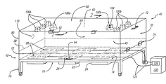
- FIG. 1 is a non-limiting diagram illustrating the system in a preferred embodiment of the present invention.
- FIG. 2 is a non-limiting diagram showing a cross-sectional view in a preferred embodiment of the present invention.
- the embodiment of the therapeutic light and sound system has a support 10 comprising a longitudinal centerline 12 , a top side 14 , and a bottom side 16 .
- the support 10 should be large enough to support the user and of sufficient strength to remain substantially rigid when subjected to the user's weight.
- materials that can be used for the support include, but are not limited to, wood, sound board, plywood, particle board, composite insulation board, plastic, glass, Plexiglas, fiberglass, metal, stone, marble, etc.
- the support material would provide a sound insulation or a sound insulating material that could be attached to the support material.
- the supporting material would preferably be substantially opaque to light transmission or could be covered with a light absorbing material.
- the supporting material could be substantially opaque, painted or covered with a light absorbing material.
- the support 10 includes at least one supporting member 19 .
- the supporting member may be a single solid base or column.
- the support 10 includes at least two supporting members.
- the support 10 includes at least four supporting members.
- FIG. 1 shows the best mode including four supporting members 19 on movable wheels.
- the support 10 further includes at least two transducers 20 arranged on opposite sides of the longitudinal centerline 12 .
- the longitudinal centerline as defined for the purposes of this invention corresponds to the right and left sides of a user which may or may not correspond to the exact centerline of support.
- the transducers corresponding to the right side of the user are also known as the right transducers and the transducers corresponding to the left side of the user are also known as the left transducers.
- Each transducer emits acoustic vibrations about the range of human auditory response.
- Light and sound vibrations can be defined by either the frequency or wavelength.
- the sound frequency range produced is from about 10 Hz to about 25,000 Hz, and more preferably sound frequency is from about 30 Hz to about 20,000 Hz.
- the transducers are also known as speakers.
- individual speakers may be full range speakers or may produce frequencies of a limited range.
- the transducers are preferably electromechanical in nature. Limited range speakers are sometimes referred to as sub-woofers, woofers, mid-range and tweeters.
- the transducers 20 on the opposite sides of the longitudinal centerline 12 are preferably separated by an attenuating barrier 22 placed between the transducers.
- the transducers may be placed in groups or placed individually.
- at least one attenuating barrier is provided to reduce transmission of acoustical waves between the transducers on opposite sides of the longitudinal centerline.
- attenuating barriers are also placed between groups of or between individual transducers on the same side.
- an attenuating housing 24 can be formed by fully enclosing the transducers, either in groups or individually, by using attenuating barriers 22 .
- FIG. 1 shows eighteen transducers 20 grouped in six sets of three attached to the bottom side of the support 10 .
- the groups of three transducers 20 are separated by attenuating barriers 22 which, in the disclosed embodiment, form attenuating housings 24 .
- the transducers 20 may be placed either above, below or mounted within the support 10 . preferably, the transducers 20 are attached to the support 10 .
- the transducers 20 may be either attached to the top side 14 , the bottom side 16 or set within the body of the support. If the transducers 20 are attached to the bottom of the support, then an acoustical transmitter 26 must be used if the support does not substantially transmit the acoustic vibrations.
- Such an acoustical transmitter may be a plurality of holes in the support, a single opening in the support, or some frequency transmitting material in the support corresponding to the transducers.
- One example of the acoustical transmitter 26 may be an opening or holes that correspond to the removal of material in any shape and extending from the bottom side 16 of the support to the to side 14 of the support that allow for the transmission of the acoustic vibrations.
- the openings or holes may remove material in the shapes of cubes, parallel pipeds, spheres, pyramids, cones, cylinders, etc.
- the opening or holes are cylindrically shaped.
- a second type of acoustical transmitter may be a frequency transmitting material that may replace the opening or holes to allow for the transmission of the acoustic vibrations.
- An enclosure module is required to create a substantially dark space at least around the user's eyes.
- an enclosure module 40 of any suitable shape, with the top side 16 of the support 10 acting as the base, forms a substantially dark space 45 such that the substantially dark space 45 is sufficiently large enough to accommodate a user.
- the enclosure module 40 would provide some sound insulation, or some sound insulating material could be attached to the inside or outside of the enclosure module 40 .
- the enclosure module 40 could be covered with a light absorbing material, and more preferably, the enclosure module 40 would be substantially opaque to light transmission.
- the enclosure module 40 could be substantially opaque, or painted or covered with a light absorbing material.
- the enclosure module 40 may be of any size but preferably the substantially dark space 45 is of sufficient size to enclose the user.
- enclosure modules that can form a substantially dark space include light excluding eye goggles or rooms from which light can be substantially excluded.
- the enclosure module 40 is made of wood and has a top 50 , a back 60 , a first 70 , a second side 80 , and a front 90 .
- Access to the interior of the substantially dark space 45 is through at least one access port.
- the front 90 and the top 50 are connected with hinges 92 that allow the front 90 to be pivotally lifted using handle 94 thereby forming an access port for the user.
- Other access ports may be created in the enclosure module 40 , the support 10 , or in combination of the enclosure module 40 and support 10 .
- a communication system is available so the user may communicate with a person outside the system.
- a second access port in the first side 70 having hinges 74 and a handle 72 is shown.
- the second access port shown in FIG. 1 may also be used to communicate with the user while maintaining the substantially dark space (i.e., a communication system) by opening the second access port slightly.
- a substantially dark space i.e., a communication system
- Other examples of mechanical and electrical methods of communication systems are available, such as two-way intercoms, etc.
- the substantially dark space 45 includes at least one selectively energized light source 100 .
- the light source or sources may be any sort of illuminating device including, but not limited to, incandescent bulbs, fluorescent lights or display terminals or combinations thereof.
- the light source 100 may be a white light source to simulate sunlight. Alternatively, the light source or sources may produce colored light by the light source itself or by using a color filter.
- FIG. 1 shows eight light sources 100 a and 100 b attached to the top 50 .
- the lights are enclosed in a multiple-sided mirrored reflector where the number of sides is at least equal to two. In the preferred embodiment of the present invention shown in FIG.
- the light sources 100 a are white light enclosed in a six-sided mirrored reflector 104 and six other light sources 100 b use colored filters or colored lights.
- the light sources produce light that is visible to the user's eye including, but not limited to, red, orange, yellow, violet, blue and green.
- the wavelengths of the light are generally between 400 nanometers and 800 nanometers.
- the light source, or light sources are coupled to the substantially dark space 45 by placing the light source, or light sources, anywhere within the substantially dark space or the light may be transmitted by transmitting light into the substantially dark space 45 by some method, such as, for example, a fiber optic.
- the light source, or sources, 100 are mounted on the enclosure module 40 in a way that light reaches the substantially dark space 45 .
- the light sources are mounted above the user. Further, the light source, or light sources, may be controlled individually or in groups by actuating switches. Preferably, the actuating switch can vary the intensity and duration of the selectively energized light or light sources. More preferably, each light source has a separate actuating switch for varying the light source intensity.
- the substantially dark space 45 may also have a temperature moderation device 110 .
- temperature moderation devices include, but are not limited to, for example, a fan, a heater and an air conditioner.
- the temperature moderation device may also provide ventilation for the user.
- FIG. 1 shows a hole 110 inserted in the second side 80 which can accommodate a fan as a temperature moderation device.
- Such devices could be mounted or equipped with light baffles to prevent unnecessary light from entering the substantially dark space 45 .
- the present invention also includes at least one sound generator 120 having at least two outputs 122 that are connected to the transducers 20 .
- the sound generator 120 may be any sort of device that generates an electrical output which may be converted into acoustic vibrations. Examples of some types of sound generators include, but are not limited to, stereo systems, radio receivers, phonographs, compact disc players, tape recorders and players, cable box decoders, satellite signal capturing devices, televisions, video cassette recorders, Internet connecting devices, etc.
- the sound generator 120 includes either an internal or external amplifier to actuate the transducers. For example, FIG. 1 shows a stereo system 120 including an external amplifier 126 .
- the sound generator 120 may be placed anywhere, but in one preferred embodiment of the present invention, the sound generator 120 may be placed on the top 50 of the enclosure module 40 and a covering unit may be made to cover the sound generator 120 .
- the acoustic vibrations produced by each of the transducers are directed upward through a mat 30 towards either the right side or left side of a user.
- the mat 30 may be of any porous material which allows the frequency vibrations to reach the user. Examples of some types of material that the mat may be composed of include, but are not limited to, polyethylene foam, sponge, cotton, and other foam rubbers and plastics, etc.
- the mat 30 may also have a covering that does not substantially reduce the frequency vibrations.
- the mat provides a cushion on which the user may lay on either the user's front or the user's back with the midline of the body of the user substantially between the right and left transducers.
- Controls for the sound generator and the actuating switches may be accessible to the user or may be controlled outside the substantially dark space 45 .
- the right transducer, or transducers, and the left transducer, or transducers may be proportionally controlled.
- An example of proportional control is balance between the right transducer, or transducers, and the left transducer or transducers.
- the right transducer, or transducers, as a set, and the left transducer, or transducers, as a set may be controlled using separate controls.
- each transducer may be controlled using a separate control.
- the lights may be selectively energized for duration and light intensity by an actuating switch.
- the present invention may also employ a controller to control the sound generator or generators, one or more light sources, or both.
- the controller may be either a specifically designed device or a general purpose computer employing a software program to control delivery of the frequency vibrations to the user.
- the controller may control any combination of the lights or the right and left transducers.
- the lights and the right and left transducers may also be controlled in a related manner such that the acoustic vibrations and light are coordinated to stimulate the user's brain.
- the present invention may also incorporate an aroma device to simulate the olfactory of the user (also known as the nose).
Abstract
Description
- This Application is a continuation application of co-pending U.S. patent application Ser. No. 09/359,819, filed on Jul. 22, 1999, and entitled “Method and Apparatus for Applying Frequency Vibrations Therapeutically”.
- This invention relates to a method and apparatus for applying Frequency Vibrations of Sound and Light (hereinafter sometimes referred to as “FVSL”) to a user for the administration of therapeutic treatment including relaxation and other benefits.
- The therapeutic benefits of utilizing light, sound, color, smell, magnetic fields and vibration are known. Medical evidence indicates that the health of people may be affected by exposure to light. For example, a condition known as Seasonal Affective Disorder occurs during seasonal periods of low light and is characterized by a depressed condition in those people so affected.
- It is also known that sound plays a substantial role in changes of pulse frequency, blood pressure, blood circulation, muscle relaxation, perspiration and oxygen consumption of a person. Previously, sound therapy has been applied to a user's ears and body, light has been applied to a user's eyes, and other stimuli have been combined to relax a user. Further, it is well known that the different parts of the human brain are known to correspond to different parts of the body; for example, the two hemispheres of the brain are known to correspond to different sides of the body. It would be advantageous over the prior art to stimulate the user's brain through the application of sound specifically and independently directed to the right and left sides of the user's body along with the application of the sound to the user's ears and light to the user's eyes.
- The object of the present invention is to provide better stimulation to a user's mind and body using acoustic vibrations, also known as sound, directed to the right and left sides of the human body and to provide a substantially dark space to the user's eyes which includes at least one light source for controlling light to the user's eyes. Certain forms of the enclosure can also act as a sound reflector to direct acoustic vibrations to the skin and ears of the user.
- The present invention relates to a method and an apparatus for applying Frequency Vibrations of Sound and Light to a user's body and eyes to facilitate physiological and psychological benefits to the user such as relaxation, and especially the application of acoustic vibrations from separate transducers to the right and left side of a user's body.
- In accordance with this invention, a method and apparatus for applying Frequency Vibrations of Sound and Light to a user using a therapeutic light and sound system are disclosed.
- The therapeutic light and sound system comprises a support structure having a longitudinal centerline, a top side, and a bottom side for supporting a user; at least two transducers arranged on opposite sides of the longitudinal centerline for producing acoustical vibrations substantially directed to the right side and left side of the user, respectively; an enclosure module for forming a substantially dark space for the user's eyes, and at least one light source coupled to the substantially dark space for transmitting light to the user's eyes. Preferably, the therapeutic light and sound system further comprise a mat placed on the top side of the support structure for cushioning the user and transmitting the acoustical waves to the right side and left side of the user's body. The invention may also include a sound generator for actuating the transducers.
- Another aspect of the invention relates to a therapeutic light and sound system comprising a support structure including: a top side for supporting a user, the user having a right side and a left side; at least one right transducer arranged on the support structure for transmitting acoustic vibrations to the right side of the user; at least one left transducer arranged on the support structure for transmitting acoustic vibrations to the left side of the user; an enclosure module for forming a substantially dark space for the user's eyes; and at least one selectively energized light source coupled to the substantially dark space for transmitting light to the user's eyes.
- The method of therapeutic treatment using light and sound comprises the steps of: supporting a user on a support structure having a top side and including at least one right transducer arranged below the user's body corresponding to the user's right side and having at least one left transducer arranged below the user's body corresponding to the user's left side; transmitting acoustical vibrations from right transducers substantially to the right side of the user's body and transmitting acoustical vibrations from the left transducers substantially to the left side of the user's body; providing an enclosure module for forming a substantially dark space for the user's eyes; and coupling at least one selectively energized light source to the substantially dark space for transmitting light to user's eyes.
- The invention will be more readily understood from a non-limiting description of a preferred embodiment that follows and from the diagrammatic figure of the drawings.
- In the drawings:
- FIG. 1 is a non-limiting diagram illustrating the system in a preferred embodiment of the present invention; and
- FIG. 2 is a non-limiting diagram showing a cross-sectional view in a preferred embodiment of the present invention.
- Referring now to FIG. 1, there is shown a schematic diagram for one embodiment of the present invention. As shown in FIG. 1, the embodiment of the therapeutic light and sound system has a
support 10 comprising alongitudinal centerline 12, atop side 14, and abottom side 16. Thesupport 10 should be large enough to support the user and of sufficient strength to remain substantially rigid when subjected to the user's weight. Examples of materials that can be used for the support include, but are not limited to, wood, sound board, plywood, particle board, composite insulation board, plastic, glass, Plexiglas, fiberglass, metal, stone, marble, etc. Preferably the support material would provide a sound insulation or a sound insulating material that could be attached to the support material. Also, the supporting material would preferably be substantially opaque to light transmission or could be covered with a light absorbing material. For example, the supporting material could be substantially opaque, painted or covered with a light absorbing material. - In a preferred embodiment of the present invention, the
support 10 includes at least one supportingmember 19. For example, the supporting member may be a single solid base or column. In a more preferred embodiment of the present invention, thesupport 10 includes at least two supporting members. In a most preferred embodiment of the present invention, thesupport 10 includes at least four supporting members. For example, FIG. 1 shows the best mode including four supportingmembers 19 on movable wheels. - The
support 10 further includes at least twotransducers 20 arranged on opposite sides of thelongitudinal centerline 12. The longitudinal centerline as defined for the purposes of this invention corresponds to the right and left sides of a user which may or may not correspond to the exact centerline of support. The transducers corresponding to the right side of the user are also known as the right transducers and the transducers corresponding to the left side of the user are also known as the left transducers. - Each transducer emits acoustic vibrations about the range of human auditory response. Light and sound vibrations can be defined by either the frequency or wavelength. Preferably the sound frequency range produced is from about 10 Hz to about 25,000 Hz, and more preferably sound frequency is from about 30 Hz to about 20,000 Hz. The transducers are also known as speakers. For example, individual speakers may be full range speakers or may produce frequencies of a limited range. The transducers are preferably electromechanical in nature. Limited range speakers are sometimes referred to as sub-woofers, woofers, mid-range and tweeters.
- The
transducers 20 on the opposite sides of thelongitudinal centerline 12 are preferably separated by anattenuating barrier 22 placed between the transducers. The transducers may be placed in groups or placed individually. Preferably, at least one attenuating barrier is provided to reduce transmission of acoustical waves between the transducers on opposite sides of the longitudinal centerline. More preferably, attenuating barriers are also placed between groups of or between individual transducers on the same side. Most preferably, anattenuating housing 24 can be formed by fully enclosing the transducers, either in groups or individually, by usingattenuating barriers 22. For example, FIG. 1 shows eighteentransducers 20 grouped in six sets of three attached to the bottom side of thesupport 10. The groups of threetransducers 20 are separated byattenuating barriers 22 which, in the disclosed embodiment, form attenuatinghousings 24. - The
transducers 20 may be placed either above, below or mounted within thesupport 10. preferably, thetransducers 20 are attached to thesupport 10. Thetransducers 20 may be either attached to thetop side 14, thebottom side 16 or set within the body of the support. If thetransducers 20 are attached to the bottom of the support, then anacoustical transmitter 26 must be used if the support does not substantially transmit the acoustic vibrations. Such an acoustical transmitter; for example, may be a plurality of holes in the support, a single opening in the support, or some frequency transmitting material in the support corresponding to the transducers. - One example of the
acoustical transmitter 26 may be an opening or holes that correspond to the removal of material in any shape and extending from thebottom side 16 of the support to the toside 14 of the support that allow for the transmission of the acoustic vibrations. For example the openings or holes may remove material in the shapes of cubes, parallel pipeds, spheres, pyramids, cones, cylinders, etc. Preferably, the opening or holes are cylindrically shaped. A second type of acoustical transmitter may be a frequency transmitting material that may replace the opening or holes to allow for the transmission of the acoustic vibrations. - An enclosure module is required to create a substantially dark space at least around the user's eyes. In the preferred embodiment shown in FIG. 1, an
enclosure module 40, of any suitable shape, with thetop side 16 of thesupport 10 acting as the base, forms a substantiallydark space 45 such that the substantiallydark space 45 is sufficiently large enough to accommodate a user. In one preferred embodiment of the present invention, theenclosure module 40 would provide some sound insulation, or some sound insulating material could be attached to the inside or outside of theenclosure module 40. In another preferred embodiment of the present invention, theenclosure module 40 could be covered with a light absorbing material, and more preferably, theenclosure module 40 would be substantially opaque to light transmission. For example, theenclosure module 40 could be substantially opaque, or painted or covered with a light absorbing material. In another embodiment of the present invention, theenclosure module 40 may be of any size but preferably the substantiallydark space 45 is of sufficient size to enclose the user. Examples of enclosure modules that can form a substantially dark space include light excluding eye goggles or rooms from which light can be substantially excluded. - In FIG. 1, the
enclosure module 40 is made of wood and has a top 50, a back 60, a first 70, asecond side 80, and a front 90. Access to the interior of the substantiallydark space 45, shown in FIG. 1, is through at least one access port. For example, in FIG. 1 the front 90 and the top 50 are connected withhinges 92 that allow the front 90 to be pivotally lifted usinghandle 94 thereby forming an access port for the user. Other access ports may be created in theenclosure module 40, thesupport 10, or in combination of theenclosure module 40 andsupport 10. Optionally, a communication system is available so the user may communicate with a person outside the system. - In the preferred embodiment of the present invention shown in FIG. 1, a second access port in the
first side 70 havinghinges 74 and ahandle 72 is shown. The second access port shown in FIG. 1 may also be used to communicate with the user while maintaining the substantially dark space (i.e., a communication system) by opening the second access port slightly. Other examples of mechanical and electrical methods of communication systems are available, such as two-way intercoms, etc. - The substantially
dark space 45 includes at least one selectively energized light source 100. The light source or sources may be any sort of illuminating device including, but not limited to, incandescent bulbs, fluorescent lights or display terminals or combinations thereof. The light source 100 may be a white light source to simulate sunlight. Alternatively, the light source or sources may produce colored light by the light source itself or by using a color filter. FIG. 1 shows eightlight sources 100 a and 100 b attached to the top 50. Preferably, the lights are enclosed in a multiple-sided mirrored reflector where the number of sides is at least equal to two. In the preferred embodiment of the present invention shown in FIG. 1, two of the light sources, 100 a, are white light enclosed in a six-sided mirroredreflector 104 and six otherlight sources 100 b use colored filters or colored lights. The light sources produce light that is visible to the user's eye including, but not limited to, red, orange, yellow, violet, blue and green. The wavelengths of the light are generally between 400 nanometers and 800 nanometers. The light source, or light sources, are coupled to the substantiallydark space 45 by placing the light source, or light sources, anywhere within the substantially dark space or the light may be transmitted by transmitting light into the substantiallydark space 45 by some method, such as, for example, a fiber optic. Preferably, the light source, or sources, 100 are mounted on theenclosure module 40 in a way that light reaches the substantiallydark space 45. More preferably, the light sources are mounted above the user. Further, the light source, or light sources, may be controlled individually or in groups by actuating switches. Preferably, the actuating switch can vary the intensity and duration of the selectively energized light or light sources. More preferably, each light source has a separate actuating switch for varying the light source intensity. - The substantially
dark space 45 may also have atemperature moderation device 110. Such temperature moderation devices include, but are not limited to, for example, a fan, a heater and an air conditioner. The temperature moderation device may also provide ventilation for the user. FIG. 1 shows ahole 110 inserted in thesecond side 80 which can accommodate a fan as a temperature moderation device. Such devices could be mounted or equipped with light baffles to prevent unnecessary light from entering the substantiallydark space 45. - The present invention also includes at least one
sound generator 120 having at least twooutputs 122 that are connected to thetransducers 20. Thesound generator 120 may be any sort of device that generates an electrical output which may be converted into acoustic vibrations. Examples of some types of sound generators include, but are not limited to, stereo systems, radio receivers, phonographs, compact disc players, tape recorders and players, cable box decoders, satellite signal capturing devices, televisions, video cassette recorders, Internet connecting devices, etc. Thesound generator 120 includes either an internal or external amplifier to actuate the transducers. For example, FIG. 1 shows astereo system 120 including anexternal amplifier 126. Thesound generator 120 may be placed anywhere, but in one preferred embodiment of the present invention, thesound generator 120 may be placed on the top 50 of theenclosure module 40 and a covering unit may be made to cover thesound generator 120. - Referring to FIG. 2, the acoustic vibrations produced by each of the transducers are directed upward through a
mat 30 towards either the right side or left side of a user. Themat 30 may be of any porous material which allows the frequency vibrations to reach the user. Examples of some types of material that the mat may be composed of include, but are not limited to, polyethylene foam, sponge, cotton, and other foam rubbers and plastics, etc. Themat 30 may also have a covering that does not substantially reduce the frequency vibrations. The mat provides a cushion on which the user may lay on either the user's front or the user's back with the midline of the body of the user substantially between the right and left transducers. - Controls for the sound generator and the actuating switches may be accessible to the user or may be controlled outside the substantially
dark space 45. Preferably, the right transducer, or transducers, and the left transducer, or transducers, may be proportionally controlled. An example of proportional control is balance between the right transducer, or transducers, and the left transducer or transducers. More preferably, the right transducer, or transducers, as a set, and the left transducer, or transducers, as a set, may be controlled using separate controls. Most preferably, each transducer may be controlled using a separate control. In another preferred embodiment of the present invention using controls, the lights may be selectively energized for duration and light intensity by an actuating switch. - The present invention may also employ a controller to control the sound generator or generators, one or more light sources, or both. The controller may be either a specifically designed device or a general purpose computer employing a software program to control delivery of the frequency vibrations to the user. In another preferred embodiment of the present invention, the controller may control any combination of the lights or the right and left transducers. The lights and the right and left transducers may also be controlled in a related manner such that the acoustic vibrations and light are coordinated to stimulate the user's brain.
- Further, the present invention may also incorporate an aroma device to simulate the olfactory of the user (also known as the nose).
- Whereas, a specific preferred embodiment of the present invention has been described, it will be understood that variations and modifications may be made without departure from the spirit and scope of the present invention as set forth in the appended claims.
Claims (20)
Priority Applications (1)
| Application Number | Priority Date | Filing Date | Title |
|---|---|---|---|
| US10/408,537 US7108654B2 (en) | 1999-07-23 | 2003-04-07 | Method and apparatus for applying frequency vibrations therapeutically |
Applications Claiming Priority (2)
| Application Number | Priority Date | Filing Date | Title |
|---|---|---|---|
| US09/359,819 US6544165B1 (en) | 1999-07-23 | 1999-07-23 | Method and apparatus for applying frequency vibrations therapeutically |
| US10/408,537 US7108654B2 (en) | 1999-07-23 | 2003-04-07 | Method and apparatus for applying frequency vibrations therapeutically |
Related Parent Applications (1)
| Application Number | Title | Priority Date | Filing Date |
|---|---|---|---|
| US09/359,819 Continuation US6544165B1 (en) | 1999-07-23 | 1999-07-23 | Method and apparatus for applying frequency vibrations therapeutically |
Related Child Applications (1)
| Application Number | Title | Priority Date | Filing Date |
|---|---|---|---|
| US11/013,778 Continuation-In-Part US7141028B2 (en) | 2003-12-17 | 2004-12-16 | Apparatus, system, and method for creating an individually, balanceable environment of sound and light |
Publications (2)
| Publication Number | Publication Date |
|---|---|
| US20030191359A1 true US20030191359A1 (en) | 2003-10-09 |
| US7108654B2 US7108654B2 (en) | 2006-09-19 |
Family
ID=23415410
Family Applications (2)
| Application Number | Title | Priority Date | Filing Date |
|---|---|---|---|
| US09/359,819 Expired - Lifetime US6544165B1 (en) | 1999-07-23 | 1999-07-23 | Method and apparatus for applying frequency vibrations therapeutically |
| US10/408,537 Expired - Fee Related US7108654B2 (en) | 1999-07-23 | 2003-04-07 | Method and apparatus for applying frequency vibrations therapeutically |
Family Applications Before (1)
| Application Number | Title | Priority Date | Filing Date |
|---|---|---|---|
| US09/359,819 Expired - Lifetime US6544165B1 (en) | 1999-07-23 | 1999-07-23 | Method and apparatus for applying frequency vibrations therapeutically |
Country Status (1)
| Country | Link |
|---|---|
| US (2) | US6544165B1 (en) |
Cited By (1)
| Publication number | Priority date | Publication date | Assignee | Title |
|---|---|---|---|---|
| US20160144151A1 (en) * | 2014-11-24 | 2016-05-26 | Barry McNew | Light and Sound Therapy Device |
Families Citing this family (35)
| Publication number | Priority date | Publication date | Assignee | Title |
|---|---|---|---|---|
| US6544165B1 (en) * | 1999-07-23 | 2003-04-08 | Mcnew Barry | Method and apparatus for applying frequency vibrations therapeutically |
| US6888537B2 (en) * | 2002-02-13 | 2005-05-03 | Siemens Technology-To-Business Center, Llc | Configurable industrial input devices that use electrically conductive elastomer |
| US9949004B2 (en) * | 2003-03-10 | 2018-04-17 | Daniel E. Cohen | Sound and vibration transmission device |
| AT413077B (en) * | 2003-08-29 | 2005-11-15 | Othegraven Achim Von | THERAPEUTIC TREATMENT DEVICE |
| US7141028B2 (en) | 2003-12-17 | 2006-11-28 | Mcnew Barry | Apparatus, system, and method for creating an individually, balanceable environment of sound and light |
| US8517911B1 (en) * | 2004-07-17 | 2013-08-27 | Jeffrey D. Thompson | Sound delivery system for vibro-acoustic treatment |
| US20060205994A1 (en) * | 2005-03-08 | 2006-09-14 | Sunnen Gerard V | Vibrational delta and theta brain wave induction apparatus and method for the stimulation of sleep |
| US20100168503A1 (en) * | 2005-03-08 | 2010-07-01 | Sunnen Gerard V | Vibrational delta and theta brain wave induction apparatus and method for the stimulation of sleep |
| US8027491B2 (en) * | 2006-03-03 | 2011-09-27 | Tactile Sound Systems, Inc. | Contact speaker |
| US20070287881A1 (en) * | 2006-04-13 | 2007-12-13 | Akimov Anatoly E | Destressing system, apparatus, and method therefor |
| US7410269B2 (en) * | 2006-06-06 | 2008-08-12 | S.C. Johnson & Son, Inc. | Decorative light system |
| US7458698B2 (en) * | 2006-06-15 | 2008-12-02 | S.C. Johnson & Son, Inc. | Decorative light system |
| US7846084B2 (en) * | 2006-11-27 | 2010-12-07 | Mcnew Barry | Apparatus, system, and method for creating an individually balanceable environment of sound and light |
| US20080135437A1 (en) * | 2006-12-11 | 2008-06-12 | Leslie Barnett Taneri | Stress relief sounds in consumer goods |
| US9504625B2 (en) * | 2008-03-31 | 2016-11-29 | Kohler Co. | Vibroacoustic water system |
| US20090241253A1 (en) * | 2008-03-31 | 2009-10-01 | Glasford Barry D | Vibroacoustic Bathing Systtem |
| US8337385B1 (en) | 2010-02-05 | 2012-12-25 | Cornell Douglas G | Cabinet having relaxation chamber with light and sound |
| WO2011125022A1 (en) * | 2010-04-08 | 2011-10-13 | Koninklijke Philips Electronics N.V. | A sound massage system |
| US9622911B2 (en) | 2010-09-30 | 2017-04-18 | Cxl Ophthalmics, Llc | Ophthalmic treatment device, system, and method of use |
| US20130071829A1 (en) * | 2011-09-19 | 2013-03-21 | Oleg Berezhkov | Way of optimization of the psycho-physiological condition of the person and the training complex |
| AU2012325893B2 (en) | 2011-10-19 | 2015-04-16 | Sympara Medical Inc. | Methods and devices for treating hypertension |
| US10226179B2 (en) * | 2012-03-27 | 2019-03-12 | Pdc Facilities, Inc. | Method, system and software product for creating variable environments in medical diagnostic imaging rooms |
| US20150088231A1 (en) * | 2012-03-28 | 2015-03-26 | Cxl Ophthalmics, Llc | Ocular treatment system and method using red and gold phototherapy |
| EP2830637A4 (en) | 2012-03-29 | 2016-03-16 | Cxl Ophthalmics Llc | Compositions and methods for treating or preventing diseases associated with oxidative stress |
| EP2830627A4 (en) | 2012-03-29 | 2015-10-14 | Cxl Ophthalmics Llc | Ocular treatment solutions, delivery devices and delivery augmentation methods |
| ES2431439B1 (en) * | 2012-05-23 | 2015-02-10 | Francesc Xavier PIRLA LLORENS | Multisensory Stimulation Device |
| WO2014115053A1 (en) * | 2013-01-23 | 2014-07-31 | Koninklijke Philips N.V. | Means for assisting human information processing |
| WO2015089297A2 (en) * | 2013-12-11 | 2015-06-18 | Ergomotion, Inc. | Vibratory system for massage and audio generation in an articulating bed |
| US20150283019A1 (en) * | 2014-04-07 | 2015-10-08 | Kugona LLC | Tactile transducer treatment system |
| CA2998840C (en) | 2015-09-22 | 2018-12-04 | Blu Room Enterprises, LLC | Apparatus for providing light therapy |
| US10863264B2 (en) * | 2017-01-23 | 2020-12-08 | David Sampson | Vibration inducing tactile apparatus |
| US10737054B1 (en) * | 2017-08-30 | 2020-08-11 | Gail Lynn | Sound and light chamber |
| US20190274874A1 (en) * | 2018-03-08 | 2019-09-12 | Anthony Michael Guarnieri | Transformation chamber |
| CA3096773A1 (en) | 2019-10-24 | 2021-04-24 | Mind Alive Inc. | Technologies for multi-randomized audio-visual entrainment |
| US11322042B2 (en) * | 2019-12-11 | 2022-05-03 | Mind Alive Inc. | Technologies for audio-visual entrainment with breathing cues for managing heart rate variability |
Citations (11)
| Publication number | Priority date | Publication date | Assignee | Title |
|---|---|---|---|---|
| US1935294A (en) * | 1928-12-03 | 1933-11-14 | Liebel Flarsheim Co | Therapeutic lamp |
| US3014477A (en) * | 1956-08-16 | 1961-12-26 | Robert L Carlin | Hypnotic inducer |
| US3085568A (en) * | 1960-08-02 | 1963-04-16 | Whitesell Harry | Physio-therapy apparatus |
| US3826250A (en) * | 1972-07-12 | 1974-07-30 | Zany Prod Inc | Apparatus |
| US4507816A (en) * | 1983-12-21 | 1985-04-02 | Smith Jr Gray H | Waterbed with sound wave system |
| US5266070A (en) * | 1991-05-28 | 1993-11-30 | Matsushita Electric Works, Ltd. | Relaxation refreshment apparatus |
| US5318503A (en) * | 1991-12-27 | 1994-06-07 | Lord Robert F | Method and apparatus for auditory and olfactory relaxation |
| US5577990A (en) * | 1993-12-28 | 1996-11-26 | Nusa Widjaja | Trophotropic response method |
| US5645578A (en) * | 1994-11-16 | 1997-07-08 | Sybaritic, Inc. | Total therapy sauna bed system |
| US5865771A (en) * | 1996-01-31 | 1999-02-02 | Atom Medical Corporation | Incubator mat apparatus with sound generator |
| US6544165B1 (en) * | 1999-07-23 | 2003-04-08 | Mcnew Barry | Method and apparatus for applying frequency vibrations therapeutically |
Family Cites Families (23)
| Publication number | Priority date | Publication date | Assignee | Title |
|---|---|---|---|---|
| US729317A (en) | 1902-05-05 | 1903-05-26 | E M M Curative Co | Means for treating nervous diseases by electromusical vibrations. |
| US3556088A (en) | 1968-07-01 | 1971-01-19 | Ida M Leonardini | Therapeutic chair |
| US3621155A (en) | 1969-09-29 | 1971-11-16 | Jackson L Pruitt | Stereo pillow |
| US3762767A (en) | 1972-03-02 | 1973-10-02 | A Powell | Environmental chair |
| GB1530688A (en) | 1975-04-08 | 1978-11-01 | Bodysonic Kk | Sound reproduction system |
| US4124249A (en) | 1977-10-25 | 1978-11-07 | Abbeloos Charles J | Sound transmitting system |
| US4354067A (en) | 1978-05-17 | 1982-10-12 | Bodysonic Kabushiki Kaisha | Audio-band electromechanical vibration converter |
| AT382784B (en) * | 1982-06-16 | 1987-04-10 | Stiegler Reinhard Dr | DEVICE FOR REDUCING MENTAL TENSIONS |
| FR2562446A1 (en) | 1984-04-04 | 1985-10-11 | Hayashibara Ken | ELECTROMAGNETIC VIBRATION GENERATOR |
| DE3541350A1 (en) | 1985-11-22 | 1987-06-04 | Pius Voegel | THERAPY DEVICE FOR THE HUMAN BODY |
| US5097821A (en) | 1987-01-02 | 1992-03-24 | Eakin Byron C | Somatic musical exposure system |
| US4778027A (en) | 1987-04-30 | 1988-10-18 | Taylor Mildred E | Rhythmizer |
| US4779615A (en) | 1987-05-13 | 1988-10-25 | Frazier Richard K | Tactile stimulator |
| IL83537A0 (en) | 1987-08-14 | 1988-01-31 | Pama Electronics | Sleep-promoting and/or pacification apparatus |
| DE3825454A1 (en) * | 1988-07-27 | 1990-02-01 | Gfpe Verlag & Seminar | LYING |
| FI81959C (en) | 1988-10-24 | 1991-01-10 | Salomo Murtonen | ANORDING FOR INFOERING AV VIBRATION I EN MAENNISKOKROPP. |
| US5024650A (en) | 1989-02-15 | 1991-06-18 | Matsushita Electric Works, Ltd. | Stress dissolving refreshment system |
| US5321763A (en) | 1990-02-17 | 1994-06-14 | Lee Jeong Gi | Body sense speaker |
| US5125031A (en) | 1991-08-14 | 1992-06-23 | Robert Ledonne | Speaker system with focused vibration |
| US5387178A (en) | 1992-11-23 | 1995-02-07 | Moses; Gary L. | Multi-stimuli chair |
| US5553148A (en) | 1994-06-20 | 1996-09-03 | Werle; Ben | Apparatus and method for producing vibratory sensations to accompany audible sounds in a properly phased relationship |
| US5725472A (en) * | 1995-12-18 | 1998-03-10 | Weathers; Lawrence R. | Psychotherapy apparatus and method for the inputting and shaping new emotional physiological and cognitive response patterns in patients |
| US5681259A (en) * | 1996-01-05 | 1997-10-28 | Healing Environments International, Inc. | Method and apparatus for biophilically promoting patient relaxation, for reducing physical and/or psychological patient stress and for expediting patient recovery |
-
1999
- 1999-07-23 US US09/359,819 patent/US6544165B1/en not_active Expired - Lifetime
-
2003
- 2003-04-07 US US10/408,537 patent/US7108654B2/en not_active Expired - Fee Related
Patent Citations (11)
| Publication number | Priority date | Publication date | Assignee | Title |
|---|---|---|---|---|
| US1935294A (en) * | 1928-12-03 | 1933-11-14 | Liebel Flarsheim Co | Therapeutic lamp |
| US3014477A (en) * | 1956-08-16 | 1961-12-26 | Robert L Carlin | Hypnotic inducer |
| US3085568A (en) * | 1960-08-02 | 1963-04-16 | Whitesell Harry | Physio-therapy apparatus |
| US3826250A (en) * | 1972-07-12 | 1974-07-30 | Zany Prod Inc | Apparatus |
| US4507816A (en) * | 1983-12-21 | 1985-04-02 | Smith Jr Gray H | Waterbed with sound wave system |
| US5266070A (en) * | 1991-05-28 | 1993-11-30 | Matsushita Electric Works, Ltd. | Relaxation refreshment apparatus |
| US5318503A (en) * | 1991-12-27 | 1994-06-07 | Lord Robert F | Method and apparatus for auditory and olfactory relaxation |
| US5577990A (en) * | 1993-12-28 | 1996-11-26 | Nusa Widjaja | Trophotropic response method |
| US5645578A (en) * | 1994-11-16 | 1997-07-08 | Sybaritic, Inc. | Total therapy sauna bed system |
| US5865771A (en) * | 1996-01-31 | 1999-02-02 | Atom Medical Corporation | Incubator mat apparatus with sound generator |
| US6544165B1 (en) * | 1999-07-23 | 2003-04-08 | Mcnew Barry | Method and apparatus for applying frequency vibrations therapeutically |
Cited By (2)
| Publication number | Priority date | Publication date | Assignee | Title |
|---|---|---|---|---|
| US20160144151A1 (en) * | 2014-11-24 | 2016-05-26 | Barry McNew | Light and Sound Therapy Device |
| US9956375B2 (en) * | 2014-11-24 | 2018-05-01 | Barry McNew | Light and sound therapy device |
Also Published As
| Publication number | Publication date |
|---|---|
| US6544165B1 (en) | 2003-04-08 |
| US7108654B2 (en) | 2006-09-19 |
Similar Documents
| Publication | Publication Date | Title |
|---|---|---|
| US6544165B1 (en) | Method and apparatus for applying frequency vibrations therapeutically | |
| US7846084B2 (en) | Apparatus, system, and method for creating an individually balanceable environment of sound and light | |
| US7654949B2 (en) | Apparatus, system, and method for creating an individually balanceable environment of sound and light | |
| US4315502A (en) | Learning-relaxation device | |
| US3585991A (en) | Psychophysiosonic system with multisensory aids | |
| CN102426624B (en) | Automatically the method and system of physical agent parameter is controlled by human body index | |
| US20060036201A1 (en) | Sound and vibration transmission pad and system | |
| US20120051579A1 (en) | Sound and Vibration Transmission Pad and System | |
| EP0244508B1 (en) | Device for influencing the human body by sound | |
| CN101244310B (en) | Music interference electric therapeutic equipment | |
| US20050207609A1 (en) | Transducer for tactile applications and apparatus incorporating transducers | |
| WO2013039305A2 (en) | Massage device having bone conduction function | |
| EP2799104A1 (en) | Apparatus for tactile, visual and aural stimulation of a user | |
| US20050234290A1 (en) | Apparatus and method for generating pulsating noise in audio device | |
| US20100124345A1 (en) | Near field sound reproduction method with enhanced spatial qualities | |
| EP0275232B1 (en) | Apparatus for relaxation and psychosensorial stimulation | |
| CN213667411U (en) | Audio therapy three-dimensional perception system and audio therapy room | |
| JP2007190408A (en) | Vibration presentation apparatus | |
| RU2195329C1 (en) | Therapeutic device | |
| KR200345666Y1 (en) | An illuminator with an embedded sleep induction device | |
| CN220558395U (en) | Music vibration physiotherapy equipment based on sleep perception | |
| CN215135482U (en) | Sleeping cabin with brain wave adjusting function | |
| FI89452B (en) | Anordning Foer att med ljud inverka pao maenniskokroppen | |
| JP2000000308A (en) | Relaxation device | |
| CA2033748A1 (en) | Vibrational sound table |
Legal Events
| Date | Code | Title | Description |
|---|---|---|---|
| CC | Certificate of correction | ||
| REMI | Maintenance fee reminder mailed | ||
| FPAY | Fee payment |
Year of fee payment: 4 |
|
| SULP | Surcharge for late payment | ||
| AS | Assignment |
Owner name: BRAKKE, JAMES, CALIFORNIA Free format text: SECURITY AGREEMENT;ASSIGNOR:MCNEW, BARRY;REEL/FRAME:027104/0021 Effective date: 20080729 |
|
| REMI | Maintenance fee reminder mailed | ||
| FPAY | Fee payment |
Year of fee payment: 8 |
|
| SULP | Surcharge for late payment |
Year of fee payment: 7 |
|
| FEPP | Fee payment procedure |
Free format text: MAINTENANCE FEE REMINDER MAILED (ORIGINAL EVENT CODE: REM.) |
|
| LAPS | Lapse for failure to pay maintenance fees |
Free format text: PATENT EXPIRED FOR FAILURE TO PAY MAINTENANCE FEES (ORIGINAL EVENT CODE: EXP.); ENTITY STATUS OF PATENT OWNER: SMALL ENTITY |
|
| STCH | Information on status: patent discontinuation |
Free format text: PATENT EXPIRED DUE TO NONPAYMENT OF MAINTENANCE FEES UNDER 37 CFR 1.362 |
|
| FP | Lapsed due to failure to pay maintenance fee |
Effective date: 20180919 |