US20030190924A1 - Method and apparatus for determining receive diversity in mobile station - Google Patents
Method and apparatus for determining receive diversity in mobile station Download PDFInfo
- Publication number
- US20030190924A1 US20030190924A1 US10/117,893 US11789302A US2003190924A1 US 20030190924 A1 US20030190924 A1 US 20030190924A1 US 11789302 A US11789302 A US 11789302A US 2003190924 A1 US2003190924 A1 US 2003190924A1
- Authority
- US
- United States
- Prior art keywords
- diversity
- receive
- transmit power
- power level
- threshold
- Prior art date
- Legal status (The legal status is an assumption and is not a legal conclusion. Google has not performed a legal analysis and makes no representation as to the accuracy of the status listed.)
- Granted
Links
Images


Classifications
-
- H—ELECTRICITY
- H04—ELECTRIC COMMUNICATION TECHNIQUE
- H04B—TRANSMISSION
- H04B7/00—Radio transmission systems, i.e. using radiation field
- H04B7/02—Diversity systems; Multi-antenna system, i.e. transmission or reception using multiple antennas
- H04B7/04—Diversity systems; Multi-antenna system, i.e. transmission or reception using multiple antennas using two or more spaced independent antennas
- H04B7/08—Diversity systems; Multi-antenna system, i.e. transmission or reception using multiple antennas using two or more spaced independent antennas at the receiving station
- H04B7/0868—Hybrid systems, i.e. switching and combining
- H04B7/0874—Hybrid systems, i.e. switching and combining using subgroups of receive antennas
-
- H—ELECTRICITY
- H04—ELECTRIC COMMUNICATION TECHNIQUE
- H04B—TRANSMISSION
- H04B7/00—Radio transmission systems, i.e. using radiation field
- H04B7/02—Diversity systems; Multi-antenna system, i.e. transmission or reception using multiple antennas
- H04B7/04—Diversity systems; Multi-antenna system, i.e. transmission or reception using multiple antennas using two or more spaced independent antennas
- H04B7/08—Diversity systems; Multi-antenna system, i.e. transmission or reception using multiple antennas using two or more spaced independent antennas at the receiving station
-
- H—ELECTRICITY
- H04—ELECTRIC COMMUNICATION TECHNIQUE
- H04B—TRANSMISSION
- H04B1/00—Details of transmission systems, not covered by a single one of groups H04B3/00 - H04B13/00; Details of transmission systems not characterised by the medium used for transmission
- H04B1/06—Receivers
- H04B1/16—Circuits
-
- H—ELECTRICITY
- H04—ELECTRIC COMMUNICATION TECHNIQUE
- H04W—WIRELESS COMMUNICATION NETWORKS
- H04W72/00—Local resource management
- H04W72/02—Selection of wireless resources by user or terminal
-
- Y—GENERAL TAGGING OF NEW TECHNOLOGICAL DEVELOPMENTS; GENERAL TAGGING OF CROSS-SECTIONAL TECHNOLOGIES SPANNING OVER SEVERAL SECTIONS OF THE IPC; TECHNICAL SUBJECTS COVERED BY FORMER USPC CROSS-REFERENCE ART COLLECTIONS [XRACs] AND DIGESTS
- Y02—TECHNOLOGIES OR APPLICATIONS FOR MITIGATION OR ADAPTATION AGAINST CLIMATE CHANGE
- Y02D—CLIMATE CHANGE MITIGATION TECHNOLOGIES IN INFORMATION AND COMMUNICATION TECHNOLOGIES [ICT], I.E. INFORMATION AND COMMUNICATION TECHNOLOGIES AIMING AT THE REDUCTION OF THEIR OWN ENERGY USE
- Y02D30/00—Reducing energy consumption in communication networks
- Y02D30/70—Reducing energy consumption in communication networks in wireless communication networks
Definitions
- the present invention relates generally to the field of communications, and more specifically, to communications using a receive diversity technique.
- the communication channel between a transmitter and a receiver is susceptible to noise, interference, and multipath. Multiple antennas may be used at the receiving destination to enhance the received signal. A receiver chain for signals received at each antenna may be necessary. Therefore, multiple receiver chains may be necessary to exploit the signals received at multiple receive antennas. Use of multiple receiver chains increases the power consumption. A mobile station in a communication system may greatly benefit from receive diversity; however, mobile stations generally have limited battery power supply.
- transmit power level of a signal targeted for a mobile station may be at a lower level when the mobile station is using receive diversity.
- Processing a received channel may be accomplished using receive diversity by combining the received signals.
- the effective carrier to noise ratio of the channel may be increased to a level above the minimum level required for processing the channel.
- the transmitter may transmit the signal at a lower power level without effecting the receive processing.
- the transmitter may be able to transmit to a larger number of mobile stations.
- Use of receiver diversity at the mobile station thus increases the capacity of the communication system; however, use of receiver diversity increases the power consumption at the mobile station.
- Performance of mobile stations is measured with respect to the length of time operating without recharging the battery power supply.
- the receiver may have to turn on multiple receiver chains to process multiple received signals. As a result, the receiver may consume a substantial amount of battery power. Therefore, use of receive diversity without any rules for decoding a received channel may adversely effect the battery life of the mobile station.
- a control system determines a demand level for use of communication resources in a communication system.
- a transmitter communicates a message indicating use of receive diversity at a mobile station based on the determined demand level.
- a receiver receives a channel and determines transmit power level of the channel for being at a lower or upper transmit power level limit.
- a control system controls receive diversity of receiver by selecting a number of plurality of receiver chains based on the determined transmit power level.
- receiver receives a channel and determines a channel condition of the channel and duration of the channel condition. Control system controls receive diversity of receiver by selecting a number of plurality of receiver chains based on the determined channel condition and the duration.
- Determining the channel condition and its duration may be based on a comparison of various thresholds, as communicated by the base station to the mobile station.
- the thresholds may include a disable-receive-diversity threshold, a receive-diversity-disable period threshold, an enable-receive-diversity threshold and a receive-diversity-enable period threshold.
- FIG. 1 depicts a communication system capable of operating in accordance with various embodiments of the invention
- FIG. 2 depicts a communication system receiver for receiving and decoding received data in accordance with various aspects of the invention
- FIG. 3 depicts a communication system transmitter for transmitting data packets in accordance with various aspects of the invention
- FIG. 4 depicts a transceiver system capable of operating in accordance with various embodiments of the invention
- FIG. 5 illustrates comparison of the transmit power level to an upper and lower limits in accordance with various embodiments of the invention.
- FIG. 6 illustrates a chart for comparison of the transmit power of a received channel to various thresholds in accordance with various embodiments of the invention
- FIG. 7 illustrates comparison of the receive channel to various thresholds in accordance with various embodiments of the invention
- FIG. 8 illustrates a chart for comparison of the receive channel to various thresholds in accordance with various embodiments of the invention.
- Various embodiments of the invention may be incorporated in a wireless communication system operating in accordance with the code division multiple access (CDMA) technique which has been disclosed and described in various standards published by the Telecommunication Industry Association (TIA) and other standards organizations.
- CDMA code division multiple access
- TIA/EIA-95 standard TIA/EIA-IS-2000 standard
- IMT-2000 standard IMT-2000 standard
- UMTS UMTS
- WCDMA Wideband Code Division Multiple Access
- a system for communication of data is also detailed in the “TIA/EIA/IS-856 cdma2000 High Rate Packet Data Air Interface Specification,” incorporated by reference herein.
- a copy of the standards may be obtained by accessing the world wide web at the address: http://www.3gpp2.org, or by writing to TIA, Standards and Technology Department, 2500 Wilson Boulevard, Arlington, Va. 22201, United States of America.
- the standard generally identified as UMTS standard, incorporated by reference herein, may be obtained by contacting 3GPP Support Office, 650 Route des Lucioles-Sophia Antipolis, Valbonne-France.
- various aspects of the invention provide for efficient use of communication resources in a CDMA communication system.
- various conditions for using receive diversity are determined.
- the use of receive diversity is determined, most likely, for conditions that produces its beneficial features, such as system capacity to accommodate more users and preventing erroneous decoding of the received data, while minimizing the impact on battery life of the mobile station.
- One or more exemplary embodiments described herein are set forth in the context of a digital wireless communication system. While use within this context is advantageous, different embodiments of the invention may be incorporated in different environments or configurations.
- the various systems described herein may be formed using software-controlled processors, integrated circuits, or discrete logic.
- the data, instructions, commands, information, signals, symbols, and chips that may be referenced throughout the application are advantageously represented by voltages, currents, electromagnetic waves, magnetic fields or particles, optical fields or particles, or a combination thereof.
- the blocks shown in each block diagram may represent hardware or method steps.
- FIG. 1 illustrates a general block diagram of a communication system 100 capable of operating in accordance with any of the code division multiple access (CDMA) communication system standards while incorporating various embodiments of the invention.
- Communication system 100 may be for communications of voice, data or both.
- communication system 100 includes a base station 101 that provides communication links between a number of mobile stations, such as mobile stations 102 - 104 , and between the mobile stations 102 - 104 and a public switch telephone and data network 105 .
- the mobile stations in FIG. 1 may be referred to as data access terminals (AT) and the base station as data access network (AN) without departing from the main scope and various advantages of the invention.
- AT data access terminals
- AN data access network
- Base station 101 may include a number of components, such as a base station controller and a base transceiver system. For simplicity, such components are not shown. Base station 101 may be in communication with other base stations, for example base station 160 . A mobile switching center (not shown) may control various operating aspects of the communication system 100 and in relation to a back-haul 199 between network 105 and base stations 101 and 160 .
- Base station 101 communicates with each mobile station that is in its coverage area via a forward link signal transmitted from base station 101 .
- the forward link signals targeted for mobile stations 102 - 104 may be summed to form a forward link signal 106 .
- Each of the mobile stations 102 - 104 receiving forward link signal 106 decodes the forward link signal 106 to extract the information that is targeted for its user.
- Base station 160 may also communicate with the mobile stations that are in its coverage area via a forward link signal transmitted from base station 160 .
- Mobile stations 102 - 104 communicate with base stations 101 and 160 via corresponding reverse links. Each reverse link is maintained by a reverse link signal, such as reverse link signals 107 - 109 for respectively mobile stations 102 - 104 .
- the reverse link signals 107 - 109 although may be targeted for one base station, may be received at other base stations.
- Base stations 101 and 160 may be simultaneously communicating to a common mobile station.
- mobile station 102 may be in close proximity of base stations 101 and 160 , which can maintain communications with both base stations 101 and 160 .
- base station 101 transmits on forward link signal 106
- base station 160 on the forward link signal 161 .
- mobile station 102 transmits on reverse link signal 107 to be received by both base stations 101 and 160 .
- one of the base stations 101 and 160 may be selected to transmit the packet of data to mobile station 102 .
- both base stations 101 and 160 may attempt to decode the traffic data transmission from the mobile station 102 .
- the communication system 100 may also employ use of pilot channels for proper decoding of various channels.
- a pilot channel contains a series of predefined data.
- a receiver receives the pilot channel to determine various characteristics of the propagation channel. One of the characteristics may be a carrier to interference ratio (Ec/Io) of the pilot channel.
- the pilot channel may be used to decode other received channels.
- the forward and reverse links may have pilot channels. On the forward link, a base station may transmit a pilot channel for all the mobile stations in its coverage area. On the reverse link, each mobile station may combine the reverse link channels with a pilot channel.
- FIG. 2 illustrates a block diagram of a receiver 200 used for processing and demodulating the received CDMA signal in accordance with various aspects of the invention.
- Receiver 200 may be used for decoding the information on the reverse and forward links signals.
- Received (Rx) samples may be stored in RAM 204 .
- Receive samples are generated by a radio frequency/intermediate frequency (RF/IF) system 290 and an antenna system 292 .
- the RF/IF system 290 and antenna system 292 may include one or more components for receiving multiple signals and RF/IF processing of the received signals for taking advantage of the receive diversity gain.
- RF/IF system 290 may include the RF/IF systems 290 A and 290 B, each being considered a receiver chain. More than two receiver chains may also be used.
- Each element of antenna system 292 receives an RF signal, and passes the received RF signal to a receiver chain in the RF/IF system 290 .
- RF/IF system 290 may be any conventional RF/IF receiver.
- the RF/IF system 290 may be a “zero” intermediate frequency (ZIF) receiver.
- the received RF signals are filtered, down-converted and digitized to form RX samples at base band frequencies.
- the samples are supplied to a demultiplexer (demux) 202 .
- the output of demux 202 is supplied to a searcher unit 206 and finger elements 208 .
- a control system 210 is coupled thereto.
- a combiner 212 couples a decoder 214 to finger elements 208 .
- Control system 210 may be a microprocessor controlled by software, and may be located on the same integrated circuit or on a separate integrated circuit.
- the decoding function in decoder 214 may be in accordance with a turbo decoder or any other suitable
- received samples are supplied to demux 202 .
- Demux 202 supplies the samples to searcher unit 206 and finger elements 208 .
- Control system 210 configures finger elements 208 to perform demodulation and despreading of the received signal at different time offsets based on search results from searcher unit 206 .
- Despreading of the channels is performed by multiplying the received samples with the complex conjugate of the PN sequence and assigned Walsh function at a single timing hypothesis and digitally filtering the resulting samples, often with an integrate and dump accumulator circuit (not shown). Such a technique is commonly known in the art.
- the searcher 206 may decode the pilot channel to determine the channel condition, such as determining Ec/Io.
- the control system 210 may decide to assign finger elements 208 to process other received channels from the same source.
- various lists of base stations with adequate pilot channel Ec/Io are kept.
- the lists may include an active list of base stations, a candidate list of base stations, a neighboring list of base stations and a remaining list of base stations.
- the lists of the base stations may be organized in accordance with the received Ec/Io level. The base stations in the active list have the strongest received Ec/Io.
- control system 210 controls the number of receiver chains used for processing the received channels based on the received channel condition, frame error rate or packet error rate, transmit power level of the channel at a transmitting base station, demand level for use of communication resources in the communication system 100 , or any combination thereof.
- Control system 210 controls the number of receiver chains used in the RF/IF system 290 .
- the scale of the receive diversity may be related to the number of selected receiver chains. Large scale receive diversity may refer to using a large number of receiver chains. When no receive diversity is used, only one receiver chain may be used. For example, when four receiver chains are available, the receive diversity scale may range from using 1 to 4 receiver chains.
- receiver 200 operates its receive diversity based on at least one of the received channel condition, frame error rate or packet error rate, transmit power level of the channel at a transmitting base station, demand level for use of communication resources in the communication system 100 , and any combination thereof.
- the receiver 200 may be incorporated in a mobile station and configured for use in the communication system 100 .
- multiple received signals may be combined in accordance with any of the commonly known combining processes, such as maximal-ratio combining (MRC) and minimum mean-squared error (MMSE).
- Temporal combining, spatial combining, or a combination of both may be used for the combining process.
- temporal combining the signals received through different propagation paths are combined.
- spatial combining the signals received at different antennas and propagated through the same path are combined.
- receiver 200 the results of the demodulation are combined in accordance with the receive diversity process, and passed the combined result to decoder 214 .
- Decoder 214 decodes the data and outputs the decoded data.
- Receiver 200 may be used in a receiver portion of base stations 101 and 160 for processing the received reverse link signals from the mobile stations, and in a receiver portion of any of the mobile stations for processing the received forward link signals.
- the performance of the received channel such as frame or packet error rate, may be communicated from decoder 214 to control system 210 for controlling receive diversity in receiver 200 , in accordance with various aspects of the invention
- FIG. 3 illustrates a block diagram of a transmitter 300 for transmitting the reverse and forward link signals.
- the channel data for transmission are input to a modulator 301 for modulation.
- the modulation may be according to any of the commonly known modulation techniques such as QAM, PSK or BPSK.
- the data is encoded at a data rate in modulator 301 .
- the data rate may be selected by a data rate and power level selector 303 .
- the data rate selection may be based on feedback information received from a receiving destination.
- the receiving destination may be a mobile station or a base station.
- the feedback information may include the maximum allowed data rate.
- the maximum allowed data rate may be determined in accordance with various commonly known algorithms. The maximum allowed data rate very often is based on the channel condition, among other considered factors.
- the data rate and power level selector 303 accordingly selects the data rate in modulator 301 .
- the output of modulator 301 passes through a signal spreading operation and amplified in a block 302 for transmission from an antenna 304 .
- the data rate and power level selector 303 also selects a power level for the amplification level of the transmitted signal in accordance with the feedback information.
- the combination of the selected data rate and the power level allows proper decoding of the transmitted data at the receiving destination.
- the transmit power level may be limited within a predefined range.
- the transmit power range may have a lower limit and an upper limit.
- the lower limit of the transmit power range may be based on the rate at which the feedback information can cause the power to increase if the channel suddenly became worse.
- the upper transmit power limit may be based on the maximum amount of power resource that the transmitter is willing to allocate to a single receiver.
- a pilot signal is also generated in a block 307 .
- the pilot signal is amplified to an appropriate level in block 307 .
- the pilot signal power level may be in accordance with the channel condition at the receiving destination.
- the pilot signal is combined with the channel signal in a combiner 308 .
- the combined signal may be amplified in an amplifier 309 and transmitted from antenna 304 .
- the antenna 304 may be in any number of combinations including antenna arrays and multiple input multiple output configurations.
- FIG. 4 depicts a general block diagram of a transceiver system 400 for incorporating receiver 200 and transmitter 300 for maintaining a communication link with a destination.
- the transceiver 400 may be incorporated in a mobile station or a base station.
- a processor 401 may be coupled to receiver 200 and transmitter 300 to process the received and transmitted data.
- Various aspects of the receiver 200 and transmitter 300 may be common, even though receiver 200 and transmitter 300 are shown separately.
- receiver 200 and transmitter 300 may share a common local oscillator and a common antenna system for RF/IF receiving and transmitting.
- transmit data processing block 403 prepares the data for transmission on a transmit channel.
- Transmitter 300 receives the data for transmission on input 405 , and transmits the data from an antenna system.
- the decoded data are received at processor 400 at an input 404 .
- Received data are processed in received data processing block 402 in processor 401 .
- Various operations of processor 401 may be integrated in a single or multiple processing units.
- the transceiver 400 may be connected to another device.
- the transceiver 400 may be an integral part of the device.
- the device may be a computer or may operate similar to a computer.
- the device may be connected to a data network, such as Internet. In case of incorporating the transceiver 400 in a base station, the base station through several connections may be connected to a network, such as Internet.
- receive diversity in a communication system may be determined for a receiver, such as receiver 200 , including a plurality of receiver chains, such as receiver chains 290 .
- the receiver 200 receives a channel and determines transmit power level of the channel for being at a lower transmit power level limit 501 or an upper transmit power level limit 502 , as shown in FIG. 5.
- the determination of the transmit power level may be based on a message sent from the transmitter to the receiver indicating the transmit power level.
- the transmitter may explicitly control the scale of diversity used by the receiver by sending a message to the receiver.
- the determination of the transmit power level may also be based on the FER experienced by the receiver.
- a control system such as control system 210 or a processor 401 , through operation of received data processing unit 402 , controls receive diversity of receiver 200 by selecting a number of the plurality of receiver chains 290 based on the determined transmit power level.
- the control system is configured for reducing the number of selected receiver chains when the determined transmit power level is at or below lower transmit power level limit 501 .
- the transmit power level is below the lower limit 501 , the channel condition is very favorable; therefore, using receive diversity may not be necessary.
- the control system is configured for increasing the number of selected receiver chains when the determined transmit power level is at or above an upper transmit power level limit 502 .
- the transmit power level is reaching its upper limit, the channel condition is not very favorable; therefore, use of receive diversity is very beneficial under such a condition.
- the determination of whether the transmit power level is below the lower limit 501 or at or above the upper limit 502 may be based on the closeness of the transmit power level to the respective transmit power limit.
- the determination of the transmit power level establishes that the transmit power level is below the lower transmit power limit 501 .
- the determination of the transmit power level establishes that the transmit power level is above the upper transmit power limit 502 .
- the upper transmit power limit 502 corresponds to a higher allowed transmit power level than a transmit power level corresponding to the lower transmit power level limit 501 , in accordance with various aspects of the invention.
- control system 210 or processor 401 may determine the transmit power level of a received signal at the receiver 200 .
- the determined transmit power level is compared to a low and high transmit power level thresholds, 501 and 502 respectively.
- the control system 210 or processor 401 may turn off or scale back the receive diversity at the receiver 200 .
- the control system 210 or processor 401 may turn on or increase the scale of the receive diversity at the receiver 200 .
- a receiver for determining receive diversity in a communication system, a receiver, such as receiver 200 , including a plurality of receiver chains, such as receiver chains 290 , receives a channel and determines a channel condition of the channel and duration of the channel condition.
- a control system such as control system 210 or processor 401 , controls receive diversity of the receiver by selecting a number of the plurality of receiver chains based on the determined channel condition and the duration of the determined channel condition.
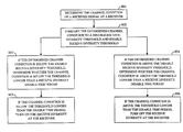
- the control system is configured for reducing the number of selected receiver chains when the determined channel condition is above a disable-receive-diversity threshold 601 and the determined duration is longer than a receive-diversity-disable period threshold 602 , shown in FIG. 7.
- the control system is configured for increasing the number of selected receiver chains when the determined channel condition is below an enable-receive-diversity threshold 603 and the determined duration is longer than a receive-diversity-enable period threshold 604 .
- the disable-receive-diversity threshold 601 corresponds to a stronger channel condition than a channel condition corresponding to the enable-receive-diversity threshold 603 .
- the disable-receive-diversity threshold, enable-receive-diversity threshold, receive-diversity-enable period, and receive-diversity-disable-period may be chosen by the receiver, or may be communicated to the receiver by the transmitter.
- the duration of the receive-diversity-enable-period and the receive-diversity-disable period may be chosen appropriately to avoid frequent switching between different degrees of receiver diversity when frequent switching may be undesirable.
- the channel condition of a receive signal at a receiver is determined.
- the parameter for determining the channel condition may be the Ec/Io or any other related parameter associated with the received signal.
- the determined channel condition is compared to disable receive diversity threshold 601 and enable receive diversity threshold 603 .
- the control system 210 or processor 401 may determine whether the channel condition is below the threshold 603 for a duration longer than the receive diversity enable time period 604 .
- the control system 210 or processor 401 may turn on or increase the scale of the receive diversity at the receiver 200 .
- the control system 210 or processor 401 may determine whether the channel condition is above the threshold 601 for a duration longer than the receive diversity disable time period 602 . If the channel condition is above the threshold 601 longer than the disable time period 602 , the control system 210 or processor 401 may turn off or decrease the scale of the receive diversity at the receiver 200 .
- control system is configured for adjusting a delta threshold 605 corresponding to a difference between the enable-receive-diversity threshold 603 and disable-receive-diversity threshold 601 .
- the adjustment of the delta threshold 605 may be based on a mobility level of the receiver in the communication system.
- the receiver may be incorporated in a mobile station in the communication system 100 .
- the control system is configured for increasing the delta threshold 605 in response to an increasing mobility level and reducing the delta threshold 605 in response to a decreasing mobility level.
- the enable-receive-diversity threshold 603 and disable-receive-diversity threshold 601 may be based on various system parameters.
- the channel condition may be measured using either the Ec/Io of the pilots transmitted by the transmitters in the receiver's Active Set, or the Ec/Io of the strongest pilot signal, or the total received power at the receiver, or the FER experienced by the receiver, etc. A combination of the above measures of channel condition may be used.
- the receiver may decide to scale down the degree of receiver diversity.
- the receiver may decide to increase the degree of receiver diversity.
- the receiver may reduce the degree of receiver diversity either irrespective of the values of the other measures, or in combination with the values of other measures.
- the measure of channel condition to use, and the thresholds for increasing or reducing the degree of receiver diversity may be chosen by the receiver on its own, or may be communicated to the receiver by the transmitter.
- the system capacity may be based on several factors. For example, the system capacity may be based on the total transmit power that a base station is allowed to transmit. The number of codes available for use on traffic channels is also another important factor. When the demand for use of the system is increased, a large number of available codes may be used, and leaving few codes for adding new traffic channels. Similarly, when the demand for use of the system is increased, the transmit power increases to near the total allowed transmit power. Under such a condition, new channels may not be added due to lack of available power. However, when a receiver is using receive diversity, the required transmit power level is lower than the level required for reception without use of diversity.
- a control system for determining receive diversity in a communication system, determines a demand level for use of communication resources in the communication system ( 100 ).
- a transmitter such as transmitter 300 , communicates a message indicating use of receive diversity at a mobile station. The message is based on the determined demand level.
- the demand level may be measured in respect to the available transmit power level, the number of codes available for allocation or a combination of factors.
- the message may be transmitted on a common or dedicated channel to the mobile station.
- the message may indicate at least one of reducing a scale, turning off, turning on and increasing scale of receive diversity at the mobile station.
- the message may indicate at least one of reducing a scale and turning off use of receive diversity at the mobile station when the demand level is lower than a predetermined level.
- the receiver may conserve battery power since the transmitter may transmit at a higher power level due to low demand.
- the message may indicate at least one of increasing scale and turning on use of receive diversity at the mobile station when the demand level is higher than a predetermined level.
- the receiver may require a lower transmit power level after turning on or increasing the scale of receive diversity.
- the receiver may feedback the need for a lower transmit power. The total transmit power is then reduced, leaving additional available power for responding to the increased system demand level.
- the base station may be selected to communicate various thresholds to the mobile station for effecting a control over use of receive diversity at various mobile stations operating in the coverage area. Therefore, the base station and the mobile stations may incorporate various ways for communication of at least one of the disable-receive-diversity threshold, receive-diversity-disable period threshold, enable-receive-diversity threshold and receive-diversity-enable period threshold. Moreover, the base station may also select which parameter, such Ec/Io or FER, for determination of the channel condition.
- the determination to use diversity and to what scale may also be based on other similar factors or a combination of similar factors.
- the parameter Ec/Io is an indication of the carrier strength over interference.
- Other similarly indicating parameters may also be used for determining the level of diversity.
- the factor “Ec” may be used instead of Ec/Io without deviating from the spirit of invention.
- the sum of the Ec/Io of all pilots in the receiver's Active Set may be used instead of the Ec/Io of the strongest pilots.
- the sum of the Ec/Io of the paths that the receiver is demodulating may be used instead.
- the parameter may be filtered to reduce noise before being used to make decisions about increasing or reducing the level of receiver diversity.
- the Ec/Io at the multiple antennas may be averaged before comparing it to the thresholds.
- the various illustrative logical blocks, modules, circuits, and algorithm steps described in connection with the embodiments disclosed herein may be implemented as electronic hardware, computer software, or combinations of both. To clearly illustrate this interchangeability of hardware and software, various illustrative components, blocks, modules, circuits, and steps have been described above generally in terms of their functionality. Whether such functionality is implemented as hardware or software depends upon the particular application and design constraints imposed on the overall system. Skilled artisans may implement the described functionality in varying ways for each particular application, but such implementation decisions should not be interpreted as causing a departure from the scope of the present invention.
- DSP digital signal processor
- ASIC application specific integrated circuit
- FPGA field programmable gate array
- a general purpose processor may be a microprocessor, but in the alternative, the processor may be any conventional processor, controller, microcontroller, or state machine.
- a processor may also be implemented as a combination of computing devices, e.g., a combination of a DSP and a microprocessor, a plurality of microprocessors, one or more microprocessors in conjunction with a DSP core, or any other such configuration.
- a software module may reside in RAM memory, flash memory, ROM memory, EPROM memory, EEPROM memory, registers, hard disk, a removable disk, a CD-ROM, or any other form of storage medium known in the art.
- An exemplary storage medium is coupled to the processor such that the processor can read information from, and write information to, the storage medium.
- the storage medium may be integral to the processor.
- the processor and the storage medium may reside in an ASIC.
- the ASIC may reside in a user terminal.
- the processor and the storage medium may reside as discrete components in a user terminal.
Abstract
For determining use of receive diversity in a mobile station, a control system (210 or 401) determines a demand level for use of communication resources. A transmitter (300) communicates a message indicating use of receive diversity at a mobile station based on the determined demand level. In another aspect, a receiver (200) receives a channel and determines transmit power level of the channel for being at a lower or upper transmit power level limit. The control system (210 or 401) controls receive diversity by selecting a number of receiver chains (290) based on the determined transmit power level. In another aspect, receiver (200) receives a channel and determines a channel condition of the channel and duration of the channel condition. Control system (210 or 401) controls receive diversity by selecting a number of receiver chains (290) based on the determined channel condition and the duration.
Description
- The present invention relates generally to the field of communications, and more specifically, to communications using a receive diversity technique.
- The communication channel between a transmitter and a receiver is susceptible to noise, interference, and multipath. Multiple antennas may be used at the receiving destination to enhance the received signal. A receiver chain for signals received at each antenna may be necessary. Therefore, multiple receiver chains may be necessary to exploit the signals received at multiple receive antennas. Use of multiple receiver chains increases the power consumption. A mobile station in a communication system may greatly benefit from receive diversity; however, mobile stations generally have limited battery power supply.
- In another aspect, transmit power level of a signal targeted for a mobile station may be at a lower level when the mobile station is using receive diversity. Processing a received channel may be accomplished using receive diversity by combining the received signals. When the signals are combined at the receiver, the effective carrier to noise ratio of the channel may be increased to a level above the minimum level required for processing the channel. As a result, the transmitter may transmit the signal at a lower power level without effecting the receive processing. As such, the transmitter may be able to transmit to a larger number of mobile stations. Use of receiver diversity at the mobile station thus increases the capacity of the communication system; however, use of receiver diversity increases the power consumption at the mobile station.
- Performance of mobile stations, in at least one aspect, is measured with respect to the length of time operating without recharging the battery power supply. To benefit from the receive diversity, the receiver may have to turn on multiple receiver chains to process multiple received signals. As a result, the receiver may consume a substantial amount of battery power. Therefore, use of receive diversity without any rules for decoding a received channel may adversely effect the battery life of the mobile station.
- To this end as well as others, there is a need for an effective use of receiver diversity for decoding various channels in a communication system.
- Method and apparatus for determining use of receive diversity in a mobile station are disclosed. In one aspect, a control system determines a demand level for use of communication resources in a communication system. A transmitter communicates a message indicating use of receive diversity at a mobile station based on the determined demand level. In another aspect, a receiver receives a channel and determines transmit power level of the channel for being at a lower or upper transmit power level limit. A control system controls receive diversity of receiver by selecting a number of plurality of receiver chains based on the determined transmit power level. In another aspect, receiver receives a channel and determines a channel condition of the channel and duration of the channel condition. Control system controls receive diversity of receiver by selecting a number of plurality of receiver chains based on the determined channel condition and the duration. Determining the channel condition and its duration may be based on a comparison of various thresholds, as communicated by the base station to the mobile station. The thresholds may include a disable-receive-diversity threshold, a receive-diversity-disable period threshold, an enable-receive-diversity threshold and a receive-diversity-enable period threshold.
- The features, objects, and advantages of the present invention will become more apparent from the detailed description set forth below when taken in conjunction with the drawings in which like reference characters identify correspondingly throughout and wherein:
- FIG. 1 depicts a communication system capable of operating in accordance with various embodiments of the invention;
- FIG. 2 depicts a communication system receiver for receiving and decoding received data in accordance with various aspects of the invention;
- FIG. 3 depicts a communication system transmitter for transmitting data packets in accordance with various aspects of the invention;
- FIG. 4 depicts a transceiver system capable of operating in accordance with various embodiments of the invention;
- FIG. 5 illustrates comparison of the transmit power level to an upper and lower limits in accordance with various embodiments of the invention; and
- FIG. 6 illustrates a chart for comparison of the transmit power of a received channel to various thresholds in accordance with various embodiments of the invention;
- FIG. 7 illustrates comparison of the receive channel to various thresholds in accordance with various embodiments of the invention;
- FIG. 8 illustrates a chart for comparison of the receive channel to various thresholds in accordance with various embodiments of the invention.
- Various embodiments of the invention may be incorporated in a wireless communication system operating in accordance with the code division multiple access (CDMA) technique which has been disclosed and described in various standards published by the Telecommunication Industry Association (TIA) and other standards organizations. Such standards include the TIA/EIA-95 standard, TIA/EIA-IS-2000 standard, IMT-2000 standard, UMTS and WCDMA standard, all incorporated by reference herein. A system for communication of data is also detailed in the “TIA/EIA/IS-856 cdma2000 High Rate Packet Data Air Interface Specification,” incorporated by reference herein. A copy of the standards may be obtained by accessing the world wide web at the address: http://www.3gpp2.org, or by writing to TIA, Standards and Technology Department, 2500 Wilson Boulevard, Arlington, Va. 22201, United States of America. The standard generally identified as UMTS standard, incorporated by reference herein, may be obtained by contacting 3GPP Support Office, 650 Route des Lucioles-Sophia Antipolis, Valbonne-France.
- Generally stated, various aspects of the invention provide for efficient use of communication resources in a CDMA communication system. In accordance with at least one aspect of the invention, various conditions for using receive diversity are determined. The use of receive diversity is determined, most likely, for conditions that produces its beneficial features, such as system capacity to accommodate more users and preventing erroneous decoding of the received data, while minimizing the impact on battery life of the mobile station.
- One or more exemplary embodiments described herein are set forth in the context of a digital wireless communication system. While use within this context is advantageous, different embodiments of the invention may be incorporated in different environments or configurations. In general, the various systems described herein may be formed using software-controlled processors, integrated circuits, or discrete logic. The data, instructions, commands, information, signals, symbols, and chips that may be referenced throughout the application are advantageously represented by voltages, currents, electromagnetic waves, magnetic fields or particles, optical fields or particles, or a combination thereof. In addition, the blocks shown in each block diagram may represent hardware or method steps.
- FIG. 1 illustrates a general block diagram of a
communication system 100 capable of operating in accordance with any of the code division multiple access (CDMA) communication system standards while incorporating various embodiments of the invention.Communication system 100 may be for communications of voice, data or both. Generally,communication system 100 includes abase station 101 that provides communication links between a number of mobile stations, such as mobile stations 102-104, and between the mobile stations 102-104 and a public switch telephone anddata network 105. The mobile stations in FIG. 1 may be referred to as data access terminals (AT) and the base station as data access network (AN) without departing from the main scope and various advantages of the invention.Base station 101 may include a number of components, such as a base station controller and a base transceiver system. For simplicity, such components are not shown.Base station 101 may be in communication with other base stations, forexample base station 160. A mobile switching center (not shown) may control various operating aspects of thecommunication system 100 and in relation to a back-haul 199 betweennetwork 105 andbase stations -
Base station 101 communicates with each mobile station that is in its coverage area via a forward link signal transmitted frombase station 101. The forward link signals targeted for mobile stations 102-104 may be summed to form aforward link signal 106. Each of the mobile stations 102-104 receivingforward link signal 106 decodes the forward link signal 106 to extract the information that is targeted for its user.Base station 160 may also communicate with the mobile stations that are in its coverage area via a forward link signal transmitted frombase station 160. Mobile stations 102-104 communicate withbase stations -
Base stations base stations base stations base station 101 transmits onforward link signal 106, andbase station 160 on theforward link signal 161. On the reverse link, mobile station 102 transmits onreverse link signal 107 to be received by bothbase stations base stations base stations - The
communication system 100 may also employ use of pilot channels for proper decoding of various channels. A pilot channel contains a series of predefined data. A receiver receives the pilot channel to determine various characteristics of the propagation channel. One of the characteristics may be a carrier to interference ratio (Ec/Io) of the pilot channel. The pilot channel may be used to decode other received channels. The forward and reverse links may have pilot channels. On the forward link, a base station may transmit a pilot channel for all the mobile stations in its coverage area. On the reverse link, each mobile station may combine the reverse link channels with a pilot channel. - FIG. 2 illustrates a block diagram of a
receiver 200 used for processing and demodulating the received CDMA signal in accordance with various aspects of the invention.Receiver 200 may be used for decoding the information on the reverse and forward links signals. Received (Rx) samples may be stored inRAM 204. Receive samples are generated by a radio frequency/intermediate frequency (RF/IF)system 290 and anantenna system 292. The RF/IF system 290 andantenna system 292 may include one or more components for receiving multiple signals and RF/IF processing of the received signals for taking advantage of the receive diversity gain. For example, RF/IFsystem 290 may include the RF/IF systems 290A and 290B, each being considered a receiver chain. More than two receiver chains may also be used. Each element ofantenna system 292 receives an RF signal, and passes the received RF signal to a receiver chain in the RF/IF system 290. RF/IF system 290 may be any conventional RF/IF receiver. The RF/IF system 290 may be a “zero” intermediate frequency (ZIF) receiver. The received RF signals are filtered, down-converted and digitized to form RX samples at base band frequencies. The samples are supplied to a demultiplexer (demux) 202. The output ofdemux 202 is supplied to asearcher unit 206 andfinger elements 208. Acontrol system 210 is coupled thereto. Acombiner 212 couples adecoder 214 to fingerelements 208.Control system 210 may be a microprocessor controlled by software, and may be located on the same integrated circuit or on a separate integrated circuit. The decoding function indecoder 214 may be in accordance with a turbo decoder or any other suitable decoding algorithms. - During operation, received samples are supplied to
demux 202.Demux 202 supplies the samples tosearcher unit 206 andfinger elements 208.Control system 210 configuresfinger elements 208 to perform demodulation and despreading of the received signal at different time offsets based on search results fromsearcher unit 206. Despreading of the channels is performed by multiplying the received samples with the complex conjugate of the PN sequence and assigned Walsh function at a single timing hypothesis and digitally filtering the resulting samples, often with an integrate and dump accumulator circuit (not shown). Such a technique is commonly known in the art. Thesearcher 206 may decode the pilot channel to determine the channel condition, such as determining Ec/Io. If the Ec/Io of the pilot channel of the transmitting source is above a threshold, thecontrol system 210 may decide to assignfinger elements 208 to process other received channels from the same source. In the mobile station, various lists of base stations with adequate pilot channel Ec/Io are kept. The lists may include an active list of base stations, a candidate list of base stations, a neighboring list of base stations and a remaining list of base stations. The lists of the base stations may be organized in accordance with the received Ec/Io level. The base stations in the active list have the strongest received Ec/Io. - In accordance with various aspects of the invention,
control system 210 controls the number of receiver chains used for processing the received channels based on the received channel condition, frame error rate or packet error rate, transmit power level of the channel at a transmitting base station, demand level for use of communication resources in thecommunication system 100, or any combination thereof.Control system 210 controls the number of receiver chains used in the RF/IF system 290. The scale of the receive diversity may be related to the number of selected receiver chains. Large scale receive diversity may refer to using a large number of receiver chains. When no receive diversity is used, only one receiver chain may be used. For example, when four receiver chains are available, the receive diversity scale may range from using 1 to 4 receiver chains. Therefore,receiver 200 operates its receive diversity based on at least one of the received channel condition, frame error rate or packet error rate, transmit power level of the channel at a transmitting base station, demand level for use of communication resources in thecommunication system 100, and any combination thereof. Thereceiver 200 may be incorporated in a mobile station and configured for use in thecommunication system 100. - For receive diversity, multiple received signals may be combined in accordance with any of the commonly known combining processes, such as maximal-ratio combining (MRC) and minimum mean-squared error (MMSE). Temporal combining, spatial combining, or a combination of both, may be used for the combining process. In temporal combining, the signals received through different propagation paths are combined. In the spatial combining, the signals received at different antennas and propagated through the same path are combined. In
receiver 200, the results of the demodulation are combined in accordance with the receive diversity process, and passed the combined result todecoder 214.Decoder 214 decodes the data and outputs the decoded data.Receiver 200 may be used in a receiver portion ofbase stations decoder 214 to controlsystem 210 for controlling receive diversity inreceiver 200, in accordance with various aspects of the invention - FIG. 3 illustrates a block diagram of a
transmitter 300 for transmitting the reverse and forward link signals. The channel data for transmission are input to amodulator 301 for modulation. The modulation may be according to any of the commonly known modulation techniques such as QAM, PSK or BPSK. The data is encoded at a data rate inmodulator 301. The data rate may be selected by a data rate andpower level selector 303. The data rate selection may be based on feedback information received from a receiving destination. The receiving destination may be a mobile station or a base station. The feedback information may include the maximum allowed data rate. The maximum allowed data rate may be determined in accordance with various commonly known algorithms. The maximum allowed data rate very often is based on the channel condition, among other considered factors. The data rate andpower level selector 303 accordingly selects the data rate inmodulator 301. The output ofmodulator 301 passes through a signal spreading operation and amplified in ablock 302 for transmission from anantenna 304. The data rate andpower level selector 303 also selects a power level for the amplification level of the transmitted signal in accordance with the feedback information. The combination of the selected data rate and the power level allows proper decoding of the transmitted data at the receiving destination. The transmit power level may be limited within a predefined range. The transmit power range may have a lower limit and an upper limit. The lower limit of the transmit power range may be based on the rate at which the feedback information can cause the power to increase if the channel suddenly became worse. The upper transmit power limit may be based on the maximum amount of power resource that the transmitter is willing to allocate to a single receiver. - A pilot signal is also generated in a
block 307. The pilot signal is amplified to an appropriate level inblock 307. The pilot signal power level may be in accordance with the channel condition at the receiving destination. The pilot signal is combined with the channel signal in acombiner 308. The combined signal may be amplified in anamplifier 309 and transmitted fromantenna 304. Theantenna 304 may be in any number of combinations including antenna arrays and multiple input multiple output configurations. - FIG. 4 depicts a general block diagram of a
transceiver system 400 for incorporatingreceiver 200 andtransmitter 300 for maintaining a communication link with a destination. Thetransceiver 400 may be incorporated in a mobile station or a base station. Aprocessor 401 may be coupled toreceiver 200 andtransmitter 300 to process the received and transmitted data. Various aspects of thereceiver 200 andtransmitter 300 may be common, even thoughreceiver 200 andtransmitter 300 are shown separately. In one aspect,receiver 200 andtransmitter 300 may share a common local oscillator and a common antenna system for RF/IF receiving and transmitting. - On the transmitting side, transmit
data processing block 403 prepares the data for transmission on a transmit channel.Transmitter 300 receives the data for transmission oninput 405, and transmits the data from an antenna system. On the receiving side, after the received data are decoded, the decoded data are received atprocessor 400 at aninput 404. Received data are processed in receiveddata processing block 402 inprocessor 401. Various operations ofprocessor 401 may be integrated in a single or multiple processing units. Thetransceiver 400 may be connected to another device. Thetransceiver 400 may be an integral part of the device. The device may be a computer or may operate similar to a computer. The device may be connected to a data network, such as Internet. In case of incorporating thetransceiver 400 in a base station, the base station through several connections may be connected to a network, such as Internet. - In accordance with various aspects of the invention, receive diversity in a communication system may be determined for a receiver, such as
receiver 200, including a plurality of receiver chains, such asreceiver chains 290. Thereceiver 200 receives a channel and determines transmit power level of the channel for being at a lower transmitpower level limit 501 or an upper transmitpower level limit 502, as shown in FIG. 5. The determination of the transmit power level may be based on a message sent from the transmitter to the receiver indicating the transmit power level. Alternately, the transmitter may explicitly control the scale of diversity used by the receiver by sending a message to the receiver. The determination of the transmit power level may also be based on the FER experienced by the receiver. For example, if the FER is much better than the target FER, the receiver may assume that the current transmit power level is at the lower limit. On the other hand, if the FER is much worse than the target FER, the receiver may assume that the transmit power is at the upper limit. A control system, such ascontrol system 210 or aprocessor 401, through operation of receiveddata processing unit 402, controls receive diversity ofreceiver 200 by selecting a number of the plurality ofreceiver chains 290 based on the determined transmit power level. The control system is configured for reducing the number of selected receiver chains when the determined transmit power level is at or below lower transmitpower level limit 501. When the transmit power level is below thelower limit 501, the channel condition is very favorable; therefore, using receive diversity may not be necessary. If the receive diversity is used under this condition, the processing power and the power consumption are unnecessarily used. The control system, moreover, is configured for increasing the number of selected receiver chains when the determined transmit power level is at or above an upper transmitpower level limit 502. When the transmit power level is reaching its upper limit, the channel condition is not very favorable; therefore, use of receive diversity is very beneficial under such a condition. The determination of whether the transmit power level is below thelower limit 501 or at or above theupper limit 502 may be based on the closeness of the transmit power level to the respective transmit power limit. For example, if the transmit power level is within 1-3 dB of the lower transmitpower limit 501, the determination of the transmit power level establishes that the transmit power level is below the lower transmitpower limit 501. Similarly, for example, if the transmit power level is within 1-3 dB of the upper transmitpower limit 502, the determination of the transmit power level establishes that the transmit power level is above the upper transmitpower limit 502. The upper transmitpower limit 502 corresponds to a higher allowed transmit power level than a transmit power level corresponding to the lower transmitpower level limit 501, in accordance with various aspects of the invention. - Referring to FIG. 6, a flow chart for determining receive diversity based on the transmit power level in accordance with various aspects of the invention is shown. At step 561,
control system 210 orprocessor 401 may determine the transmit power level of a received signal at thereceiver 200. Atstep 652, the determined transmit power level is compared to a low and high transmit power level thresholds, 501 and 502 respectively. Atstep 653, if the transmit power level is at or within a margin of the low transmitpower level limit 501, thecontrol system 210 orprocessor 401 may turn off or scale back the receive diversity at thereceiver 200. Atstep 654, if the transmit power level is at or within a margin of the high transmitpower level limit 502, thecontrol system 210 orprocessor 401 may turn on or increase the scale of the receive diversity at thereceiver 200. - Furthermore, in accordance with various aspects of the invention, for determining receive diversity in a communication system, a receiver, such as
receiver 200, including a plurality of receiver chains, such asreceiver chains 290, receives a channel and determines a channel condition of the channel and duration of the channel condition. A control system, such ascontrol system 210 orprocessor 401, controls receive diversity of the receiver by selecting a number of the plurality of receiver chains based on the determined channel condition and the duration of the determined channel condition. The control system is configured for reducing the number of selected receiver chains when the determined channel condition is above a disable-receive-diversity threshold 601 and the determined duration is longer than a receive-diversity-disableperiod threshold 602, shown in FIG. 7. The control system is configured for increasing the number of selected receiver chains when the determined channel condition is below an enable-receive-diversity threshold 603 and the determined duration is longer than a receive-diversity-enableperiod threshold 604. The disable-receive-diversity threshold 601 corresponds to a stronger channel condition than a channel condition corresponding to the enable-receive-diversity threshold 603. As a result, thereceiver 200 while being incorporated in a mobile station benefits from use of receive diversity when the condition for use of receive diversity is beneficial. The system resources are conserved. The disable-receive-diversity threshold, enable-receive-diversity threshold, receive-diversity-enable period, and receive-diversity-disable-period may be chosen by the receiver, or may be communicated to the receiver by the transmitter. The duration of the receive-diversity-enable-period and the receive-diversity-disable period may be chosen appropriately to avoid frequent switching between different degrees of receiver diversity when frequent switching may be undesirable. - Referring to FIG. 8, a flow chart for determining receive diversity in a receiver in accordance with various aspects of the invention is shown. At
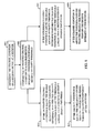
step 801, the channel condition of a receive signal at a receiver is determined. The parameter for determining the channel condition may be the Ec/Io or any other related parameter associated with the received signal. Atstep 802, the determined channel condition is compared to disable receivediversity threshold 601 and enable receivediversity threshold 603. Atstep 803, if the determined channel condition is below the enable receivediversity threshold 603, thecontrol system 210 orprocessor 401 may determine whether the channel condition is below thethreshold 603 for a duration longer than the receive diversity enabletime period 604. If the channel condition is below thethreshold 603 longer than the enabletime period 604, thecontrol system 210 orprocessor 401 may turn on or increase the scale of the receive diversity at thereceiver 200. Atstep 804, if the determined channel condition is above the disable receivediversity threshold 601, thecontrol system 210 orprocessor 401 may determine whether the channel condition is above thethreshold 601 for a duration longer than the receive diversity disabletime period 602. If the channel condition is above thethreshold 601 longer than the disabletime period 602, thecontrol system 210 orprocessor 401 may turn off or decrease the scale of the receive diversity at thereceiver 200. - Furthermore, the control system is configured for adjusting a
delta threshold 605 corresponding to a difference between the enable-receive-diversity threshold 603 and disable-receive-diversity threshold 601. The adjustment of thedelta threshold 605 may be based on a mobility level of the receiver in the communication system. The receiver may be incorporated in a mobile station in thecommunication system 100. The control system is configured for increasing thedelta threshold 605 in response to an increasing mobility level and reducing thedelta threshold 605 in response to a decreasing mobility level. - In accordance with various aspects of the invention, the enable-receive-
diversity threshold 603 and disable-receive-diversity threshold 601 may be based on various system parameters. The channel condition may be measured using either the Ec/Io of the pilots transmitted by the transmitters in the receiver's Active Set, or the Ec/Io of the strongest pilot signal, or the total received power at the receiver, or the FER experienced by the receiver, etc. A combination of the above measures of channel condition may be used. - For example, if the Ec/Io of the strongest pilot is high, and the received power is high, the receiver may decide to scale down the degree of receiver diversity. On the other hand, if the received power is high, but the Ec/Io of the strongest pilot is low, the receiver may decide to increase the degree of receiver diversity. Similarly, if the FER is low, the receiver may reduce the degree of receiver diversity either irrespective of the values of the other measures, or in combination with the values of other measures. The measure of channel condition to use, and the thresholds for increasing or reducing the degree of receiver diversity may be chosen by the receiver on its own, or may be communicated to the receiver by the transmitter.
- The system capacity may be based on several factors. For example, the system capacity may be based on the total transmit power that a base station is allowed to transmit. The number of codes available for use on traffic channels is also another important factor. When the demand for use of the system is increased, a large number of available codes may be used, and leaving few codes for adding new traffic channels. Similarly, when the demand for use of the system is increased, the transmit power increases to near the total allowed transmit power. Under such a condition, new channels may not be added due to lack of available power. However, when a receiver is using receive diversity, the required transmit power level is lower than the level required for reception without use of diversity.
- In accordance with various aspects of the invention, for determining receive diversity in a communication system, a control system, such as a base station controller incorporated in a base station, determines a demand level for use of communication resources in the communication system ( 100). A transmitter, such as
transmitter 300, communicates a message indicating use of receive diversity at a mobile station. The message is based on the determined demand level. The demand level may be measured in respect to the available transmit power level, the number of codes available for allocation or a combination of factors. The message may be transmitted on a common or dedicated channel to the mobile station. The message may indicate at least one of reducing a scale, turning off, turning on and increasing scale of receive diversity at the mobile station. The message may indicate at least one of reducing a scale and turning off use of receive diversity at the mobile station when the demand level is lower than a predetermined level. As such, the receiver may conserve battery power since the transmitter may transmit at a higher power level due to low demand. The message may indicate at least one of increasing scale and turning on use of receive diversity at the mobile station when the demand level is higher than a predetermined level. As such, the receiver may require a lower transmit power level after turning on or increasing the scale of receive diversity. As a result, the receiver may feedback the need for a lower transmit power. The total transmit power is then reduced, leaving additional available power for responding to the increased system demand level. - Generally stated, the base station may be selected to communicate various thresholds to the mobile station for effecting a control over use of receive diversity at various mobile stations operating in the coverage area. Therefore, the base station and the mobile stations may incorporate various ways for communication of at least one of the disable-receive-diversity threshold, receive-diversity-disable period threshold, enable-receive-diversity threshold and receive-diversity-enable period threshold. Moreover, the base station may also select which parameter, such Ec/Io or FER, for determination of the channel condition.
- The determination to use diversity and to what scale may also be based on other similar factors or a combination of similar factors. Moreover, the parameter Ec/Io is an indication of the carrier strength over interference. Other similarly indicating parameters may also be used for determining the level of diversity. For example, the factor “Ec” may be used instead of Ec/Io without deviating from the spirit of invention. The sum of the Ec/Io of all pilots in the receiver's Active Set may be used instead of the Ec/Io of the strongest pilots. Alternately, the sum of the Ec/Io of the paths that the receiver is demodulating may be used instead. The parameter may be filtered to reduce noise before being used to make decisions about increasing or reducing the level of receiver diversity. When the receiver uses multiple antennas, the Ec/Io at the multiple antennas may be averaged before comparing it to the thresholds. Those of skill in the art would further appreciate that the various illustrative logical blocks, modules, circuits, and algorithm steps described in connection with the embodiments disclosed herein may be implemented as electronic hardware, computer software, or combinations of both. To clearly illustrate this interchangeability of hardware and software, various illustrative components, blocks, modules, circuits, and steps have been described above generally in terms of their functionality. Whether such functionality is implemented as hardware or software depends upon the particular application and design constraints imposed on the overall system. Skilled artisans may implement the described functionality in varying ways for each particular application, but such implementation decisions should not be interpreted as causing a departure from the scope of the present invention.
- The various illustrative logical blocks, modules, and circuits described in connection with the embodiments disclosed herein may be implemented or performed with a general purpose processor, a digital signal processor (DSP), an application specific integrated circuit (ASIC), a field programmable gate array (FPGA) or other programmable logic device, discrete gate or transistor logic, discrete hardware components, or any combination thereof designed to perform the functions described herein. A general purpose processor may be a microprocessor, but in the alternative, the processor may be any conventional processor, controller, microcontroller, or state machine. A processor may also be implemented as a combination of computing devices, e.g., a combination of a DSP and a microprocessor, a plurality of microprocessors, one or more microprocessors in conjunction with a DSP core, or any other such configuration.
- The steps of a method or algorithm described in connection with the embodiments disclosed herein may be embodied directly in hardware, in a software module executed by a processor, or in a combination. A software module may reside in RAM memory, flash memory, ROM memory, EPROM memory, EEPROM memory, registers, hard disk, a removable disk, a CD-ROM, or any other form of storage medium known in the art. An exemplary storage medium is coupled to the processor such that the processor can read information from, and write information to, the storage medium. In the alternative, the storage medium may be integral to the processor. The processor and the storage medium may reside in an ASIC. The ASIC may reside in a user terminal. In the alternative, the processor and the storage medium may reside as discrete components in a user terminal.
- The previous description of the preferred embodiments is provided to enable any person skilled in the art to make or use the present invention. The various modifications to these embodiments will be readily apparent to those skilled in the art, and the generic principles defined herein may be applied to other embodiments without the use of the inventive faculty. Thus, the present invention is not intended to be limited to the embodiments shown herein but is to be accorded the widest scope consistent with the principles and novel features disclosed herein.
Claims (30)
1. An apparatus for determining receive diversity in a communication system, comprising:
a control system for determining a demand level for use of communication resources in said communication system;
a transmitter for communicating a message indicating use of receive diversity at a mobile station, wherein said message is based on said determined demand level.
2. The apparatus as recited in claim 1 wherein said message indicates at least one of reducing a scale, turning off, turning on and increasing scale of receive diversity at said mobile station.
3. The apparatus as recited in claim 1 wherein said message indicates at least one of reducing a scale and turning off use of receive diversity at said mobile station when said demand level is lower than a predetermined level.
4. The apparatus as recited in claim 1 wherein said message indicates at least one of increasing scale and turning on use of receive diversity at said mobile station when said demand level is higher than a predetermined level.
5. A method for determining receive diversity in a communication system, comprising:
determining a demand level for use of communication resources in said communication system;
communicating a message indicating use of receive diversity at a mobile station in said communication system, wherein said message is based on said determined demand level.
6. The method as recited in claim 5 further comprising:
determining, for indication by said message, at least one of reducing a scale, turning off, turning on and increasing scale of receive diversity at said mobile station.
7. The method as recited in claim 5 further comprising:
determining, for indication by said message, at least one of reducing a scale and turning off use of receive diversity at said mobile station when said demand level is lower than a predetermined level.
8. The method as recited in claim 5 further comprising:
determining, for indication by said message, at least one of increasing scale and turning on use of receive diversity at said mobile station when said demand level is higher than a predetermined level.
9. An apparatus for determining receive diversity in a communication system, comprising:
a receiver, including a plurality of receiver chains, for receiving a channel and determining transmit power level of said channel for being at a lower or upper transmit power level limit;
a control system for controlling receive diversity of said receiver by selecting a number of said plurality of receiver chains based on said determined transmit power level.
10. The apparatus as recited in claim 9 wherein said control system is configured for reducing said number of selected receiver chains when said determined transmit power level is below said lower transmit power level limit.
11. The apparatus as recited in claim 9 wherein said control system is configured for increasing said number of selected receiver chains when said determined transmit power level is above said upper transmit power level limit.
12. The apparatus as recited in claim 9 wherein said control system is configured for reducing said number of selected receiver chains when said determined transmit power level is below said lower transmit power level limit and increasing said number of selected receiver chains when said determined transmit power level is above said upper transmit power level limit, wherein said upper transmit power limit corresponds to a higher allowed transmit power level than a transmit power level corresponding to said lower transmit power level limit.
13. A method for determining receive diversity in a communication system, comprising:
determining transmit power level of a channel, received at a receiver including a plurality of receiver chains, for being at a lower or upper transmit power level limit;
selecting a number of said plurality of receiver chains based on said determined transmit power level for controlling receive diversity of said receiver.
14. The method as recited in claim 13 further comprising:
reducing said number of selected receiver chains when said determined transmit power level is below said lower transmit power level limit.
15. The method as recited in claim 13 further comprising:
increasing said number of selected receiver chains when said determined transmit power level is above said upper transmit power level limit.
16. The method as recited in claim 13 further comprising:
reducing said number of selected receiver chains when said determined transmit power level is below said lower transmit power level limit and increasing said number of selected receiver chains when said determined transmit power level is above said upper transmit power level limit, wherein said upper transmit power limit corresponds to a higher allowed transmit power level than a transmit power level corresponding to said lower transmit power level limit.
17. An apparatus for determining receive diversity in a communication system, comprising:
a receiver, including a plurality of receiver chains, for receiving a channel and determining a channel condition of said channel and duration of said channel condition;
a control system for controlling receive diversity of said receiver by selecting a number of said plurality of receiver chains based on said determined channel condition and said duration.
18. The apparatus as recited in claim 17 wherein said control system is configured for reducing said number of selected receiver chains when said determined channel condition is above a disable-receive-diversity threshold and said determined duration is longer than a receive-diversity-disable period threshold.
19. The apparatus as recited in claim 17 wherein said control system is configured for increasing said number of selected receiver chains when said determined channel condition is below an enable-receive-diversity threshold and said determined duration is longer than a receive-diversity-enable period threshold.
20. The apparatus as recited in claim 17 wherein said control system is configured for reducing said number of selected receiver chains when said determined channel condition is above a disable-receive-diversity threshold and said determined duration is longer than a receive-diversity-disable period threshold and increasing said number of selected receiver chains when said determined channel condition is below an enable-receive-diversity threshold and said determined duration is longer than a receive-diversity-enable period threshold, wherein said disable-receive-diversity threshold corresponds to a stronger channel condition than a channel condition corresponding to said enable-receive-diversity threshold.
21. The apparatus as recited in claim 17 wherein said control system is configured for adjusting a delta threshold corresponding to a difference between said enable-receive-diversity and disable-receive-diversity thresholds based on a mobility level of said receiver in said communication system.
22. The apparatus as recited in claim 21 wherein said control system is configured for increasing said delta threshold in response to an increasing mobility level and reducing said delta threshold in response to a decreasing mobility level.
23. The apparatus as recited in claim 20 further comprising means for communication, between a base station and a mobile station, of at least one of said disable-receive-diversity threshold, said receive-diversity-disable period threshold, said enable-receive-diversity threshold and said receive-diversity-enable period threshold.
24. A method for determining receive diversity in a communication system, comprising:
determining a channel condition of a channel received at a receiver, including a plurality of receiver chains, and duration of said channel condition;
controlling receive diversity of said receiver by selecting a number of said plurality of receiver chains based on said determined channel condition and said duration.
25. The method as recited in claim 24 further comprising:
reducing said number of selected receiver chains when said determined channel condition is above a disable-receive-diversity threshold and said determined duration is longer than a receive-diversity-disable period threshold.
26. The method as recited in claim 24 further comprising:
increasing said number of selected receiver chains when said determined channel condition is below an enable-receive-diversity threshold and said determined duration is longer than a receive-diversity-enable period threshold.
27. The method as recited in claim 24 further comprising:
reducing said number of selected receiver chains when said determined channel condition is above a disable-receive-diversity threshold and said determined duration is longer than a receive-diversity-disable period threshold and increasing said number of selected receiver chains when said determined channel condition is below an enable-receive-diversity threshold and said determined duration is longer than a receive-diversity-enable period threshold, wherein said disable-receive-diversity threshold corresponds to a stronger channel condition than a channel condition corresponding to said enable-receive-diversity threshold.
28. The method as recited in claim 27 further comprising:
adjusting a delta threshold corresponding to a difference between said enable-receive-diversity and disable-receive-diversity thresholds based on a mobility level of said receiver in said communication system.
29. The method as recited in claim 28 further comprising:
increasing said delta threshold in response to an increasing mobility level and reducing said delta threshold in response to a decreasing mobility level. We should add claims for sending the above mentioned thresholds from the transmitter to the receiver.
30. The method as recited in claim 27 further comprising communicating, between a base station and a mobile station, at least one of said disable-receive-diversity threshold, said receive-diversity-disable period threshold, said enable-receive-diversity threshold and said receive-diversity-enable period threshold.
Priority Applications (14)
| Application Number | Priority Date | Filing Date | Title |
|---|---|---|---|
| US10/117,893 US7072628B2 (en) | 2002-04-05 | 2002-04-05 | Method and apparatus for determining receive diversity in mobile station |
| KR1020047015850A KR101050061B1 (en) | 2002-04-05 | 2003-04-04 | Method and apparatus for determining receive diversity at mobile station |
| PCT/US2003/010513 WO2003088521A2 (en) | 2002-04-05 | 2003-04-04 | Method and apparatus for determining receive diversity in mobile station |
| JP2003585319A JP2005522933A (en) | 2002-04-05 | 2003-04-04 | Method and apparatus for determining receive diversity in a mobile station |
| TW092107738A TWI304688B (en) | 2002-04-05 | 2003-04-04 | Method and apparatus for determining receive diversity in mobile station |
| AU2003220674A AU2003220674A1 (en) | 2002-04-05 | 2003-04-04 | Method and apparatus for determining receive diversity in mobile station |
| BRPI0309029-9A BR0309029A (en) | 2002-04-05 | 2003-04-04 | method and equipment for determining the diversity received at a mobile station |
| CNB038122480A CN100401651C (en) | 2002-04-05 | 2003-04-04 | Method and apparatus for determining receive diversity in mobile station |
| EP03716995A EP1497931A2 (en) | 2002-04-05 | 2003-04-04 | Method and apparatus for determining receive diversity in mobile station |
| ARP030101213A AR039390A1 (en) | 2002-04-05 | 2003-04-07 | METHOD AND APPLIANCE TO DETERMINE THE DIVERSITY OF RECEPTION IN A MOBILE STATION |
| HK06100726.5A HK1081014A1 (en) | 2002-04-05 | 2006-01-17 | Method and apparatus for determining receive diversity in mobile station |
| JP2009062195A JP5166328B2 (en) | 2002-04-05 | 2009-03-16 | Method and apparatus for determining receive diversity in a mobile station |
| JP2009062196A JP5237160B2 (en) | 2002-04-05 | 2009-03-16 | Method and apparatus for determining receive diversity in a mobile station |
| JP2010060976A JP2010200329A (en) | 2002-04-05 | 2010-03-17 | Method and apparatus for determining reception diversity in mobile station |
Applications Claiming Priority (1)
| Application Number | Priority Date | Filing Date | Title |
|---|---|---|---|
| US10/117,893 US7072628B2 (en) | 2002-04-05 | 2002-04-05 | Method and apparatus for determining receive diversity in mobile station |
Publications (2)
| Publication Number | Publication Date |
|---|---|
| US20030190924A1 true US20030190924A1 (en) | 2003-10-09 |
| US7072628B2 US7072628B2 (en) | 2006-07-04 |
Family
ID=28674305
Family Applications (1)
| Application Number | Title | Priority Date | Filing Date |
|---|---|---|---|
| US10/117,893 Expired - Lifetime US7072628B2 (en) | 2002-04-05 | 2002-04-05 | Method and apparatus for determining receive diversity in mobile station |
Country Status (11)
| Country | Link |
|---|---|
| US (1) | US7072628B2 (en) |
| EP (1) | EP1497931A2 (en) |
| JP (4) | JP2005522933A (en) |
| KR (1) | KR101050061B1 (en) |
| CN (1) | CN100401651C (en) |
| AR (1) | AR039390A1 (en) |
| AU (1) | AU2003220674A1 (en) |
| BR (1) | BR0309029A (en) |
| HK (1) | HK1081014A1 (en) |
| TW (1) | TWI304688B (en) |
| WO (1) | WO2003088521A2 (en) |
Cited By (23)
| Publication number | Priority date | Publication date | Assignee | Title |
|---|---|---|---|---|
| US20040106398A1 (en) * | 2002-10-03 | 2004-06-03 | Audio-Technica U.S., Inc. | Method and apparatus for remote control of an audio source such as a wireless microphone system |
| US20040203451A1 (en) * | 2002-04-19 | 2004-10-14 | Alcatel | Method for transmitting a signal between a terminal and a network component |
| EP1564909A2 (en) * | 2004-02-13 | 2005-08-17 | Pioneer Corporation | Receiver, method of receiving, and computer product |
| US20050197080A1 (en) * | 2004-03-05 | 2005-09-08 | Fatih Ulupinar | Method and apparatus for receive diversity control in wireless communications |
| WO2005088864A1 (en) * | 2004-03-05 | 2005-09-22 | Qualcomm Incorporated | Multi-antenna receive diversity control in wireless communications |
| US20060222122A1 (en) * | 2005-03-31 | 2006-10-05 | Pantech Co., Ltd. | Method for implementing diversity in mobile telephone and mobile telephone incorporating the same |
| US20060268762A1 (en) * | 2005-05-25 | 2006-11-30 | Francis Dominique | Method of path monitoring in a wireless communication system |
| US20070055472A1 (en) * | 2005-08-23 | 2007-03-08 | Cisco Technology, Inc. | Method and system for transfer of data in a wireless network |
| US20070184811A1 (en) * | 2006-02-09 | 2007-08-09 | Ballantyne Gary J | Adaptive receiver for wireless communication device |
| US20080081624A1 (en) * | 2006-09-29 | 2008-04-03 | Andres Reial | Inter-network handover optimization for terminals using advanced receivers |
| US20080159373A1 (en) * | 2006-12-14 | 2008-07-03 | Qualcomm Incorporated | Method and apparatus for operating a diversity receiver with an equalizer and a rake receiver |
| WO2008095973A1 (en) * | 2007-02-07 | 2008-08-14 | T.O.P. Optimized Technologies, S.L. | Method and apparatus for receive diversity control in wireless communication systems |
| US20080220819A1 (en) * | 2007-03-08 | 2008-09-11 | David Ben-Eli | Dynamically reconfigurable receiver |
| US20090080580A1 (en) * | 2006-03-16 | 2009-03-26 | Matsushita Electric Industrial Co., Ltd. | Diversity receiver |
| US20090111406A1 (en) * | 2007-10-30 | 2009-04-30 | Harri Posti | Diversity reception in radio receiver |
| US20100035570A1 (en) * | 2007-02-06 | 2010-02-11 | Panasonic Corporation | Receiver and receiving system using the same |
| US20100226465A1 (en) * | 2006-03-28 | 2010-09-09 | Matsushita Electric Industrial Co. Ltd. | Diversity receiver and diversity receiving method |
| US20120009881A1 (en) * | 2008-05-29 | 2012-01-12 | Kyocera Corporation | Mobile communication device and communication control method |
| US8254861B2 (en) | 2009-01-16 | 2012-08-28 | Vodafone Group Plc | Controlling x-way receiver diversity |
| WO2012115757A1 (en) * | 2011-02-24 | 2012-08-30 | Motorola Mobility Llc | Diversity control in a wireless communications device |
| US20130051258A1 (en) * | 2011-02-18 | 2013-02-28 | Chien-Jen Huang | Method of Controlling Receive Diversity for Battery Lifetime Improvement and Related Communication Device |
| WO2014074249A1 (en) * | 2012-11-07 | 2014-05-15 | Qualcomm Incorporated | Dcch-aligned receive diversity |
| US11211979B2 (en) | 2017-02-21 | 2021-12-28 | Samsung Electronics Co., Ltd. | Method and apparatus for controlling transmission power in wireless communication system |
Families Citing this family (49)
| Publication number | Priority date | Publication date | Assignee | Title |
|---|---|---|---|---|
| US20040008648A1 (en) * | 2002-07-11 | 2004-01-15 | Schmidl Timothy M. | Diversity decisions for downlink antenna transmission |
| US7715508B2 (en) | 2005-11-15 | 2010-05-11 | Tensorcomm, Incorporated | Iterative interference cancellation using mixed feedback weights and stabilizing step sizes |
| KR100631668B1 (en) * | 2003-05-13 | 2006-10-09 | 엘지전자 주식회사 | Mobile station reception diversity apparatus and method in high speed data transmission method mobile communication system |
| US7929921B2 (en) * | 2003-06-10 | 2011-04-19 | Motorola Mobility, Inc. | Diversity control in wireless communications devices and methods |
| KR100547805B1 (en) * | 2003-08-30 | 2006-01-31 | 삼성전자주식회사 | Reverse Link Coupling Apparatus and Method in Mobile Communication System Supporting Softener Handoff |
| EP1533916A1 (en) * | 2003-11-18 | 2005-05-25 | Mitsubishi Electric Information Technology Centre Europe B.V. | Diversity switch combiner |
| EP1533917A1 (en) * | 2003-11-18 | 2005-05-25 | Mitsubishi Electric Information Technology Centre Europe B.V. | Antenna diversity switch for a receiver system and method using this switch |
| US7613423B2 (en) * | 2004-09-10 | 2009-11-03 | Samsung Electronics Co., Ltd. | Method of creating active multipaths for mimo wireless systems |
| JP4566671B2 (en) | 2004-09-27 | 2010-10-20 | 京セラ株式会社 | Mobile communication terminal and data reception method for mobile communication terminal |
| US20060125689A1 (en) * | 2004-12-10 | 2006-06-15 | Narayan Anand P | Interference cancellation in a receive diversity system |
| US7826516B2 (en) * | 2005-11-15 | 2010-11-02 | Rambus Inc. | Iterative interference canceller for wireless multiple-access systems with multiple receive antennas |
| US7991088B2 (en) | 2005-11-15 | 2011-08-02 | Tommy Guess | Iterative interference cancellation using mixed feedback weights and stabilizing step sizes |
| KR100626945B1 (en) * | 2005-04-26 | 2006-09-20 | 주식회사 팬택 | Method for controlling power of consumption in mobile phone, and mobile phone implementing the same |
| JP4667118B2 (en) * | 2005-05-17 | 2011-04-06 | 株式会社エヌ・ティ・ティ・ドコモ | Diversity receiver and control method for diversity reception operation |
| US7684779B2 (en) * | 2005-05-31 | 2010-03-23 | Broadcom Corporation | Wireless terminal baseband processor high speed turbo decoding module |
| JP4708910B2 (en) * | 2005-08-09 | 2011-06-22 | 株式会社エヌ・ティ・ティ・ドコモ | Mobile communication system control method, control apparatus, and mobile communication system |
| WO2007037636A2 (en) * | 2005-09-28 | 2007-04-05 | Lg Electronics Inc. | A method of identifying a space-time encoded signal in a wireless communication system |
| US7623602B2 (en) * | 2005-11-15 | 2009-11-24 | Tensorcomm, Inc. | Iterative interference canceller for wireless multiple-access systems employing closed loop transmit diversity |
| US20070110135A1 (en) * | 2005-11-15 | 2007-05-17 | Tommy Guess | Iterative interference cancellation for MIMO-OFDM receivers |
| WO2008020294A2 (en) * | 2006-08-14 | 2008-02-21 | Nokia Corporation | Reduced performance mode when receiving a common control channel |
| EP2109941B1 (en) | 2007-02-05 | 2013-10-30 | BlackBerry Limited | Apparatus, and associated method, for operating upon received data at a receiving station capable of diversity operation |
| US7877514B2 (en) | 2007-05-03 | 2011-01-25 | Samsung Electronics Co., Ltd. | System and method for time-constrained transmission of video in a communication system |
| US7969921B2 (en) * | 2007-08-29 | 2011-06-28 | Samsung Electronics Co., Ltd. | Method and system for data packet communication in wireless communication systems |
| WO2009050538A1 (en) * | 2007-10-18 | 2009-04-23 | Freescale Semiconductor, Inc. | Prolonging internal power supply life in a mobile communication device |
| US8411664B2 (en) * | 2007-11-05 | 2013-04-02 | Telefonaktiebolaget Lm Ericsson (Publ) | Random access preamble collision detection |
| US8086195B2 (en) * | 2008-02-22 | 2011-12-27 | Motorola Mobility, Inc. | Communication unit and method of operation therefor |
| CA2713468C (en) | 2009-08-20 | 2013-11-26 | Research In Motion Limited | Method for controlling of receive diversity in an antenna system |
| WO2011094961A1 (en) * | 2010-02-04 | 2011-08-11 | 华为终端有限公司 | Method and device for controlling working mode of data card and data card |
| CN101834644A (en) * | 2010-02-04 | 2010-09-15 | 华为终端有限公司 | Wireless terminal and auxiliary antenna state control method thereof |
| WO2012148684A1 (en) * | 2011-04-27 | 2012-11-01 | President And Fellows Of Harvard College | Cell-friendly inverse opal hydrogels for cell encapsulation, drug and protein delivery, and functional nanoparticle encapsulation |
| US9301130B2 (en) | 2011-11-07 | 2016-03-29 | Intel Deutschland Gmbh | Base station, method for controlling a communication terminal, communication terminal and method for operating a communication terminal |
| TWI486036B (en) * | 2011-11-14 | 2015-05-21 | Innovative Sonic Corp | Method and apparatus for improving low-cost mtc devices in a wireless communication system |
| KR101888852B1 (en) | 2011-12-02 | 2018-09-21 | 삼성전자주식회사 | Apparatus and method for providing diversity service antenna in portable terminal |
| US9226175B2 (en) | 2013-03-14 | 2015-12-29 | Apple Inc. | Adaptive use of receiver diversity |
| CN113595620B (en) | 2015-04-10 | 2023-03-28 | 维尔塞特公司 | End-to-end beam forming system, satellite and communication method thereof |
| US10187141B2 (en) | 2015-04-10 | 2019-01-22 | Viasat, Inc. | Cross-band system for end-to-end beamforming |
| US10659112B1 (en) | 2018-11-05 | 2020-05-19 | XCOM Labs, Inc. | User equipment assisted multiple-input multiple-output downlink configuration |
| US10756860B2 (en) | 2018-11-05 | 2020-08-25 | XCOM Labs, Inc. | Distributed multiple-input multiple-output downlink configuration |
| US10432272B1 (en) | 2018-11-05 | 2019-10-01 | XCOM Labs, Inc. | Variable multiple-input multiple-output downlink user equipment |
| US10812216B2 (en) | 2018-11-05 | 2020-10-20 | XCOM Labs, Inc. | Cooperative multiple-input multiple-output downlink scheduling |
| AU2019388921A1 (en) | 2018-11-27 | 2021-06-03 | XCOM Labs, Inc. | Non-coherent cooperative multiple-input multiple-output communications |
| US11063645B2 (en) | 2018-12-18 | 2021-07-13 | XCOM Labs, Inc. | Methods of wirelessly communicating with a group of devices |
| US10756795B2 (en) | 2018-12-18 | 2020-08-25 | XCOM Labs, Inc. | User equipment with cellular link and peer-to-peer link |
| US11330649B2 (en) | 2019-01-25 | 2022-05-10 | XCOM Labs, Inc. | Methods and systems of multi-link peer-to-peer communications |
| US10756767B1 (en) | 2019-02-05 | 2020-08-25 | XCOM Labs, Inc. | User equipment for wirelessly communicating cellular signal with another user equipment |
| US10686502B1 (en) | 2019-04-29 | 2020-06-16 | XCOM Labs, Inc. | Downlink user equipment selection |
| US10735057B1 (en) | 2019-04-29 | 2020-08-04 | XCOM Labs, Inc. | Uplink user equipment selection |
| US11411778B2 (en) | 2019-07-12 | 2022-08-09 | XCOM Labs, Inc. | Time-division duplex multiple input multiple output calibration |
| US11411779B2 (en) | 2020-03-31 | 2022-08-09 | XCOM Labs, Inc. | Reference signal channel estimation |
Citations (3)
| Publication number | Priority date | Publication date | Assignee | Title |
|---|---|---|---|---|
| US5267261A (en) * | 1992-03-05 | 1993-11-30 | Qualcomm Incorporated | Mobile station assisted soft handoff in a CDMA cellular communications system |
| US6678508B1 (en) * | 2000-02-07 | 2004-01-13 | Ericsson Inc. | Power conservation method for mobile communications device with two receivers |
| US6724828B1 (en) * | 1999-01-19 | 2004-04-20 | Texas Instruments Incorporated | Mobile switching between STTD and non-diversity mode |
Family Cites Families (16)
| Publication number | Priority date | Publication date | Assignee | Title |
|---|---|---|---|---|
| JPH05183476A (en) * | 1992-01-07 | 1993-07-23 | Fujitsu Ltd | Diversity receiver after detection |
| JP3310363B2 (en) * | 1993-01-08 | 2002-08-05 | 株式会社ザナヴィ・インフォマティクス | Automatic switching device for antenna mounted on moving object |
| FI932605A (en) * | 1993-06-07 | 1994-12-08 | Nokia Telecommunications Oy | Receiver device for base station |
| JPH09149012A (en) * | 1995-11-24 | 1997-06-06 | Oki Electric Ind Co Ltd | Diversity receiver |
| JPH1093489A (en) * | 1996-09-17 | 1998-04-10 | Toshiba Corp | Radio communication equipment and diversity reception method |
| ATE274189T1 (en) * | 1997-08-18 | 2004-09-15 | Amersham Plc | PROXIMITY SCINTILLATION TEST |
| JPH11150497A (en) * | 1997-11-17 | 1999-06-02 | Matsushita Electric Ind Co Ltd | Diversity receiver |
| DE19849780C1 (en) * | 1998-10-28 | 2000-09-21 | Siemens Ag | Signal transmission method for radio communication transmitting speech and image-information |
| JP3554207B2 (en) * | 1998-11-10 | 2004-08-18 | 松下電器産業株式会社 | Wireless communication device and wireless communication method |
| JP2000165272A (en) * | 1998-11-27 | 2000-06-16 | Matsushita Electric Ind Co Ltd | Radio base station unit |
| JP2000196512A (en) * | 1998-12-25 | 2000-07-14 | Nec Mobile Commun Ltd | Diversity control circuit for mobile communication unit and diversity control method |
| JP2000217144A (en) * | 1999-01-21 | 2000-08-04 | Canon Inc | Radio communication equipment capable of changing communication rate, radio communication system and control method therefor |
| US7024168B1 (en) * | 1999-07-07 | 2006-04-04 | Telefonaktiebolaget L M Ericsson (Publ) | Controlled antenna diversity |
| DE19935675A1 (en) * | 1999-07-29 | 2001-02-15 | Bosch Gmbh Robert | Circuit for switching between receiving antennas |
| JP3631083B2 (en) * | 2000-02-14 | 2005-03-23 | 三洋電機株式会社 | Radio base station and mobile station |
| JP2003526993A (en) * | 2000-03-09 | 2003-09-09 | モトローラ・インコーポレイテッド | Method and apparatus for changing receiver finger assignments |
-
2002
- 2002-04-05 US US10/117,893 patent/US7072628B2/en not_active Expired - Lifetime
-
2003
- 2003-04-04 BR BRPI0309029-9A patent/BR0309029A/en not_active IP Right Cessation
- 2003-04-04 KR KR1020047015850A patent/KR101050061B1/en active IP Right Grant
- 2003-04-04 AU AU2003220674A patent/AU2003220674A1/en not_active Abandoned
- 2003-04-04 JP JP2003585319A patent/JP2005522933A/en not_active Withdrawn
- 2003-04-04 CN CNB038122480A patent/CN100401651C/en not_active Expired - Fee Related
- 2003-04-04 EP EP03716995A patent/EP1497931A2/en not_active Withdrawn
- 2003-04-04 WO PCT/US2003/010513 patent/WO2003088521A2/en active Application Filing
- 2003-04-04 TW TW092107738A patent/TWI304688B/en not_active IP Right Cessation
- 2003-04-07 AR ARP030101213A patent/AR039390A1/en active IP Right Grant
-
2006
- 2006-01-17 HK HK06100726.5A patent/HK1081014A1/en not_active IP Right Cessation
-
2009
- 2009-03-16 JP JP2009062195A patent/JP5166328B2/en not_active Expired - Fee Related
- 2009-03-16 JP JP2009062196A patent/JP5237160B2/en not_active Expired - Lifetime
-
2010
- 2010-03-17 JP JP2010060976A patent/JP2010200329A/en active Pending
Patent Citations (3)
| Publication number | Priority date | Publication date | Assignee | Title |
|---|---|---|---|---|
| US5267261A (en) * | 1992-03-05 | 1993-11-30 | Qualcomm Incorporated | Mobile station assisted soft handoff in a CDMA cellular communications system |
| US6724828B1 (en) * | 1999-01-19 | 2004-04-20 | Texas Instruments Incorporated | Mobile switching between STTD and non-diversity mode |
| US6678508B1 (en) * | 2000-02-07 | 2004-01-13 | Ericsson Inc. | Power conservation method for mobile communications device with two receivers |
Cited By (45)
| Publication number | Priority date | Publication date | Assignee | Title |
|---|---|---|---|---|
| US20040203451A1 (en) * | 2002-04-19 | 2004-10-14 | Alcatel | Method for transmitting a signal between a terminal and a network component |
| US20040106398A1 (en) * | 2002-10-03 | 2004-06-03 | Audio-Technica U.S., Inc. | Method and apparatus for remote control of an audio source such as a wireless microphone system |
| US7693289B2 (en) * | 2002-10-03 | 2010-04-06 | Audio-Technica U.S., Inc. | Method and apparatus for remote control of an audio source such as a wireless microphone system |
| US20100189273A1 (en) * | 2002-10-03 | 2010-07-29 | Audio-Technica U.S., Inc. | Method and apparatus for remote control of an audio source such as a wireless microphone system |
| EP1564909A3 (en) * | 2004-02-13 | 2007-08-01 | Pioneer Corporation | Receiver, method of receiving, and computer product |
| EP1564909A2 (en) * | 2004-02-13 | 2005-08-17 | Pioneer Corporation | Receiver, method of receiving, and computer product |
| US20050181755A1 (en) * | 2004-02-13 | 2005-08-18 | Pioneer Corporation | Receiver, method of receiving, and computer product |
| US20100210235A1 (en) * | 2004-03-05 | 2010-08-19 | Qualcomm Incorporated | Method and apparatus for receiver diversity control in wireless communications |
| WO2005084379A3 (en) * | 2004-03-05 | 2006-05-18 | Qualcomm Inc | Method and apparatus for receive diversity control in wireless communications |
| US8160648B2 (en) * | 2004-03-05 | 2012-04-17 | Qualcomm Incorporated | Method and apparatus for receiver diversity control in wireless communications |
| KR100809795B1 (en) * | 2004-03-05 | 2008-03-07 | 콸콤 인코포레이티드 | Multi-antenna receive diversity control in wireless communications |
| WO2005088864A1 (en) * | 2004-03-05 | 2005-09-22 | Qualcomm Incorporated | Multi-antenna receive diversity control in wireless communications |
| WO2005084379A2 (en) | 2004-03-05 | 2005-09-15 | Qualcomm Incorporated | Method and apparatus for receive diversity control in wireless communications |
| US20050197080A1 (en) * | 2004-03-05 | 2005-09-08 | Fatih Ulupinar | Method and apparatus for receive diversity control in wireless communications |
| US7925302B2 (en) * | 2004-03-05 | 2011-04-12 | Qualcomm Incorporated | Method and apparatus for receive diversity control in wireless communications |
| US20060222122A1 (en) * | 2005-03-31 | 2006-10-05 | Pantech Co., Ltd. | Method for implementing diversity in mobile telephone and mobile telephone incorporating the same |
| US20060268762A1 (en) * | 2005-05-25 | 2006-11-30 | Francis Dominique | Method of path monitoring in a wireless communication system |
| US20070055472A1 (en) * | 2005-08-23 | 2007-03-08 | Cisco Technology, Inc. | Method and system for transfer of data in a wireless network |
| US8060041B2 (en) * | 2006-02-09 | 2011-11-15 | Qualcomm, Incorporated | Adaptive receiver for wireless communication device |
| US20070184811A1 (en) * | 2006-02-09 | 2007-08-09 | Ballantyne Gary J | Adaptive receiver for wireless communication device |
| US20090080580A1 (en) * | 2006-03-16 | 2009-03-26 | Matsushita Electric Industrial Co., Ltd. | Diversity receiver |
| US8194809B2 (en) * | 2006-03-28 | 2012-06-05 | Panasonic Corporation | Diversity receiver and diversity receiving method |
| US20100226465A1 (en) * | 2006-03-28 | 2010-09-09 | Matsushita Electric Industrial Co. Ltd. | Diversity receiver and diversity receiving method |
| US20080081624A1 (en) * | 2006-09-29 | 2008-04-03 | Andres Reial | Inter-network handover optimization for terminals using advanced receivers |
| US8594171B2 (en) * | 2006-12-14 | 2013-11-26 | Qualcomm Incorporated | Method and apparatus for operating a diversity receiver with an equalizer and a rake receiver |
| US20080159373A1 (en) * | 2006-12-14 | 2008-07-03 | Qualcomm Incorporated | Method and apparatus for operating a diversity receiver with an equalizer and a rake receiver |
| US20100035570A1 (en) * | 2007-02-06 | 2010-02-11 | Panasonic Corporation | Receiver and receiving system using the same |
| WO2008095973A1 (en) * | 2007-02-07 | 2008-08-14 | T.O.P. Optimized Technologies, S.L. | Method and apparatus for receive diversity control in wireless communication systems |
| WO2009027829A3 (en) * | 2007-03-08 | 2009-09-17 | Marvell International Ltd. | Dynamically reconfigurable receiver |
| US20080220819A1 (en) * | 2007-03-08 | 2008-09-11 | David Ben-Eli | Dynamically reconfigurable receiver |
| WO2009027829A2 (en) * | 2007-03-08 | 2009-03-05 | Marvell International Ltd. | Dynamically reconfigurable receiver |
| US8385294B2 (en) | 2007-03-08 | 2013-02-26 | Marvell Israel (M.I.S.L) Ltd. | Dynamically reconfigurable receiver |
| US8614992B1 (en) | 2007-03-08 | 2013-12-24 | Marvell World Trade Ltd. | Dynamically reconfigurable receiver |
| US20090111406A1 (en) * | 2007-10-30 | 2009-04-30 | Harri Posti | Diversity reception in radio receiver |
| US8351884B2 (en) | 2007-10-30 | 2013-01-08 | Nokia Corporation | Diversity reception in radio receiver |
| WO2009056673A1 (en) * | 2007-10-30 | 2009-05-07 | Nokia Corporation | Diversity reception in radio receiver |
| US20120009881A1 (en) * | 2008-05-29 | 2012-01-12 | Kyocera Corporation | Mobile communication device and communication control method |
| US9070984B2 (en) * | 2008-05-29 | 2015-06-30 | Kyocera Corporation | Mobile communication device and communication control method |
| US8254861B2 (en) | 2009-01-16 | 2012-08-28 | Vodafone Group Plc | Controlling x-way receiver diversity |
| US20130051258A1 (en) * | 2011-02-18 | 2013-02-28 | Chien-Jen Huang | Method of Controlling Receive Diversity for Battery Lifetime Improvement and Related Communication Device |
| CN103392300A (en) * | 2011-02-24 | 2013-11-13 | 摩托罗拉移动有限责任公司 | Diversity control in a wireless communications device |
| US8873660B2 (en) | 2011-02-24 | 2014-10-28 | Motorola Mobility Llc | Diversity control in a wireless communications device |
| WO2012115757A1 (en) * | 2011-02-24 | 2012-08-30 | Motorola Mobility Llc | Diversity control in a wireless communications device |
| WO2014074249A1 (en) * | 2012-11-07 | 2014-05-15 | Qualcomm Incorporated | Dcch-aligned receive diversity |
| US11211979B2 (en) | 2017-02-21 | 2021-12-28 | Samsung Electronics Co., Ltd. | Method and apparatus for controlling transmission power in wireless communication system |
Also Published As
| Publication number | Publication date |
|---|---|
| JP5166328B2 (en) | 2013-03-21 |
| TW200307409A (en) | 2003-12-01 |
| JP2009260946A (en) | 2009-11-05 |
| JP2005522933A (en) | 2005-07-28 |
| AR039390A1 (en) | 2005-02-16 |
| KR101050061B1 (en) | 2011-07-19 |
| JP5237160B2 (en) | 2013-07-17 |
| CN100401651C (en) | 2008-07-09 |
| WO2003088521A3 (en) | 2004-03-18 |
| AU2003220674A1 (en) | 2003-10-27 |
| EP1497931A2 (en) | 2005-01-19 |
| HK1081014A1 (en) | 2006-05-04 |
| WO2003088521A2 (en) | 2003-10-23 |
| JP2009246961A (en) | 2009-10-22 |
| US7072628B2 (en) | 2006-07-04 |
| TWI304688B (en) | 2008-12-21 |
| BR0309029A (en) | 2007-01-09 |
| JP2010200329A (en) | 2010-09-09 |
| KR20040097282A (en) | 2004-11-17 |
| CN1656712A (en) | 2005-08-17 |
Similar Documents
| Publication | Publication Date | Title |
|---|---|---|
| US7072628B2 (en) | Method and apparatus for determining receive diversity in mobile station | |
| US7245600B2 (en) | Method and apparatus for determining reverse link load level for reverse link data scheduling in a CDMA communication system | |
| AU2003202868C1 (en) | Method and apparatus for controlling communications of data from multiple base stations to a mobile station in a communication system | |
| CA2509093C (en) | Switched antenna transmit diversity | |
| US7480270B2 (en) | Method and apparatus for a reverse link supplemental channel scheduling | |
| US8031622B2 (en) | Method and apparatus for receive diversity in a communication system | |
| US20070025427A1 (en) | Method and apparatus for controlling gain level of a communication channel in a CDMA communication system | |
| US7167458B2 (en) | Method and apparatus for determining a number of times a message is transmitted on a paging channel to a mobile station |
Legal Events
| Date | Code | Title | Description |
|---|---|---|---|
| AS | Assignment |
Owner name: QUALCOMM INCORPORATED, A DELAWARE CORPORATION, CAL Free format text: ASSIGNMENT OF ASSIGNORS INTEREST;ASSIGNORS:AGASHE, PARAG A.;BLACK, PETER J.;PADOVANI, ROBERTO;REEL/FRAME:013083/0865;SIGNING DATES FROM 20020701 TO 20020708 |
|
| STCF | Information on status: patent grant |
Free format text: PATENTED CASE |
|
| FPAY | Fee payment |
Year of fee payment: 4 |
|
| FPAY | Fee payment |
Year of fee payment: 8 |
|
| MAFP | Maintenance fee payment |
Free format text: PAYMENT OF MAINTENANCE FEE, 12TH YEAR, LARGE ENTITY (ORIGINAL EVENT CODE: M1553) Year of fee payment: 12 |