US20030190220A1 - Substrate transfer shuttle - Google Patents
Substrate transfer shuttle Download PDFInfo
- Publication number
- US20030190220A1 US20030190220A1 US09/881,009 US88100901A US2003190220A1 US 20030190220 A1 US20030190220 A1 US 20030190220A1 US 88100901 A US88100901 A US 88100901A US 2003190220 A1 US2003190220 A1 US 2003190220A1
- Authority
- US
- United States
- Prior art keywords
- substrate
- chamber
- shuttle
- load lock
- processing
- Prior art date
- Legal status (The legal status is an assumption and is not a legal conclusion. Google has not performed a legal analysis and makes no representation as to the accuracy of the status listed.)
- Granted
Links
Images


Classifications
-
- H—ELECTRICITY
- H01—ELECTRIC ELEMENTS
- H01L—SEMICONDUCTOR DEVICES NOT COVERED BY CLASS H10
- H01L21/00—Processes or apparatus adapted for the manufacture or treatment of semiconductor or solid state devices or of parts thereof
- H01L21/67—Apparatus specially adapted for handling semiconductor or electric solid state devices during manufacture or treatment thereof; Apparatus specially adapted for handling wafers during manufacture or treatment of semiconductor or electric solid state devices or components ; Apparatus not specifically provided for elsewhere
- H01L21/677—Apparatus specially adapted for handling semiconductor or electric solid state devices during manufacture or treatment thereof; Apparatus specially adapted for handling wafers during manufacture or treatment of semiconductor or electric solid state devices or components ; Apparatus not specifically provided for elsewhere for conveying, e.g. between different workstations
- H01L21/67739—Apparatus specially adapted for handling semiconductor or electric solid state devices during manufacture or treatment thereof; Apparatus specially adapted for handling wafers during manufacture or treatment of semiconductor or electric solid state devices or components ; Apparatus not specifically provided for elsewhere for conveying, e.g. between different workstations into and out of processing chamber
- H01L21/67748—Apparatus specially adapted for handling semiconductor or electric solid state devices during manufacture or treatment thereof; Apparatus specially adapted for handling wafers during manufacture or treatment of semiconductor or electric solid state devices or components ; Apparatus not specifically provided for elsewhere for conveying, e.g. between different workstations into and out of processing chamber horizontal transfer of a single workpiece
-
- H—ELECTRICITY
- H01—ELECTRIC ELEMENTS
- H01L—SEMICONDUCTOR DEVICES NOT COVERED BY CLASS H10
- H01L21/00—Processes or apparatus adapted for the manufacture or treatment of semiconductor or solid state devices or of parts thereof
-
- C—CHEMISTRY; METALLURGY
- C03—GLASS; MINERAL OR SLAG WOOL
- C03B—MANUFACTURE, SHAPING, OR SUPPLEMENTARY PROCESSES
- C03B25/00—Annealing glass products
- C03B25/04—Annealing glass products in a continuous way
- C03B25/06—Annealing glass products in a continuous way with horizontal displacement of the glass products
- C03B25/08—Annealing glass products in a continuous way with horizontal displacement of the glass products of glass sheets
-
- C—CHEMISTRY; METALLURGY
- C03—GLASS; MINERAL OR SLAG WOOL
- C03B—MANUFACTURE, SHAPING, OR SUPPLEMENTARY PROCESSES
- C03B29/00—Reheating glass products for softening or fusing their surfaces; Fire-polishing; Fusing of margins
- C03B29/04—Reheating glass products for softening or fusing their surfaces; Fire-polishing; Fusing of margins in a continuous way
- C03B29/06—Reheating glass products for softening or fusing their surfaces; Fire-polishing; Fusing of margins in a continuous way with horizontal displacement of the products
- C03B29/08—Glass sheets
-
- C—CHEMISTRY; METALLURGY
- C03—GLASS; MINERAL OR SLAG WOOL
- C03B—MANUFACTURE, SHAPING, OR SUPPLEMENTARY PROCESSES
- C03B35/00—Transporting of glass products during their manufacture, e.g. hot glass lenses, prisms
- C03B35/14—Transporting hot glass sheets or ribbons, e.g. by heat-resistant conveyor belts or bands
- C03B35/142—Transporting hot glass sheets or ribbons, e.g. by heat-resistant conveyor belts or bands by travelling transporting tables
-
- C—CHEMISTRY; METALLURGY
- C03—GLASS; MINERAL OR SLAG WOOL
- C03B—MANUFACTURE, SHAPING, OR SUPPLEMENTARY PROCESSES
- C03B35/00—Transporting of glass products during their manufacture, e.g. hot glass lenses, prisms
- C03B35/14—Transporting hot glass sheets or ribbons, e.g. by heat-resistant conveyor belts or bands
- C03B35/20—Transporting hot glass sheets or ribbons, e.g. by heat-resistant conveyor belts or bands by gripping tongs or supporting frames
- C03B35/202—Transporting hot glass sheets or ribbons, e.g. by heat-resistant conveyor belts or bands by gripping tongs or supporting frames by supporting frames
-
- C—CHEMISTRY; METALLURGY
- C03—GLASS; MINERAL OR SLAG WOOL
- C03C—CHEMICAL COMPOSITION OF GLASSES, GLAZES OR VITREOUS ENAMELS; SURFACE TREATMENT OF GLASS; SURFACE TREATMENT OF FIBRES OR FILAMENTS MADE FROM GLASS, MINERALS OR SLAGS; JOINING GLASS TO GLASS OR OTHER MATERIALS
- C03C17/00—Surface treatment of glass, not in the form of fibres or filaments, by coating
- C03C17/001—General methods for coating; Devices therefor
- C03C17/002—General methods for coating; Devices therefor for flat glass, e.g. float glass
-
- F—MECHANICAL ENGINEERING; LIGHTING; HEATING; WEAPONS; BLASTING
- F27—FURNACES; KILNS; OVENS; RETORTS
- F27D—DETAILS OR ACCESSORIES OF FURNACES, KILNS, OVENS, OR RETORTS, IN SO FAR AS THEY ARE OF KINDS OCCURRING IN MORE THAN ONE KIND OF FURNACE
- F27D3/00—Charging; Discharging; Manipulation of charge
-
- F—MECHANICAL ENGINEERING; LIGHTING; HEATING; WEAPONS; BLASTING
- F27—FURNACES; KILNS; OVENS; RETORTS
- F27D—DETAILS OR ACCESSORIES OF FURNACES, KILNS, OVENS, OR RETORTS, IN SO FAR AS THEY ARE OF KINDS OCCURRING IN MORE THAN ONE KIND OF FURNACE
- F27D5/00—Supports, screens, or the like for the charge within the furnace
-
- H—ELECTRICITY
- H01—ELECTRIC ELEMENTS
- H01L—SEMICONDUCTOR DEVICES NOT COVERED BY CLASS H10
- H01L21/00—Processes or apparatus adapted for the manufacture or treatment of semiconductor or solid state devices or of parts thereof
- H01L21/67—Apparatus specially adapted for handling semiconductor or electric solid state devices during manufacture or treatment thereof; Apparatus specially adapted for handling wafers during manufacture or treatment of semiconductor or electric solid state devices or components ; Apparatus not specifically provided for elsewhere
- H01L21/67005—Apparatus not specifically provided for elsewhere
- H01L21/67011—Apparatus for manufacture or treatment
- H01L21/67155—Apparatus for manufacturing or treating in a plurality of work-stations
- H01L21/67161—Apparatus for manufacturing or treating in a plurality of work-stations characterized by the layout of the process chambers
- H01L21/67173—Apparatus for manufacturing or treating in a plurality of work-stations characterized by the layout of the process chambers in-line arrangement
-
- H—ELECTRICITY
- H01—ELECTRIC ELEMENTS
- H01L—SEMICONDUCTOR DEVICES NOT COVERED BY CLASS H10
- H01L21/00—Processes or apparatus adapted for the manufacture or treatment of semiconductor or solid state devices or of parts thereof
- H01L21/67—Apparatus specially adapted for handling semiconductor or electric solid state devices during manufacture or treatment thereof; Apparatus specially adapted for handling wafers during manufacture or treatment of semiconductor or electric solid state devices or components ; Apparatus not specifically provided for elsewhere
- H01L21/67005—Apparatus not specifically provided for elsewhere
- H01L21/67011—Apparatus for manufacture or treatment
- H01L21/67155—Apparatus for manufacturing or treating in a plurality of work-stations
- H01L21/67236—Apparatus for manufacturing or treating in a plurality of work-stations the substrates being processed being not semiconductor wafers, e.g. leadframes or chips
-
- C—CHEMISTRY; METALLURGY
- C03—GLASS; MINERAL OR SLAG WOOL
- C03B—MANUFACTURE, SHAPING, OR SUPPLEMENTARY PROCESSES
- C03B2225/00—Transporting hot glass sheets during their manufacture
- C03B2225/02—Means for positioning, aligning or orientating the sheets during their travel, e.g. stops
-
- Y—GENERAL TAGGING OF NEW TECHNOLOGICAL DEVELOPMENTS; GENERAL TAGGING OF CROSS-SECTIONAL TECHNOLOGIES SPANNING OVER SEVERAL SECTIONS OF THE IPC; TECHNICAL SUBJECTS COVERED BY FORMER USPC CROSS-REFERENCE ART COLLECTIONS [XRACs] AND DIGESTS
- Y02—TECHNOLOGIES OR APPLICATIONS FOR MITIGATION OR ADAPTATION AGAINST CLIMATE CHANGE
- Y02P—CLIMATE CHANGE MITIGATION TECHNOLOGIES IN THE PRODUCTION OR PROCESSING OF GOODS
- Y02P40/00—Technologies relating to the processing of minerals
- Y02P40/50—Glass production, e.g. reusing waste heat during processing or shaping
- Y02P40/57—Improving the yield, e-g- reduction of reject rates
-
- Y—GENERAL TAGGING OF NEW TECHNOLOGICAL DEVELOPMENTS; GENERAL TAGGING OF CROSS-SECTIONAL TECHNOLOGIES SPANNING OVER SEVERAL SECTIONS OF THE IPC; TECHNICAL SUBJECTS COVERED BY FORMER USPC CROSS-REFERENCE ART COLLECTIONS [XRACs] AND DIGESTS
- Y10—TECHNICAL SUBJECTS COVERED BY FORMER USPC
- Y10S—TECHNICAL SUBJECTS COVERED BY FORMER USPC CROSS-REFERENCE ART COLLECTIONS [XRACs] AND DIGESTS
- Y10S414/00—Material or article handling
- Y10S414/135—Associated with semiconductor wafer handling
- Y10S414/139—Associated with semiconductor wafer handling including wafer charging or discharging means for vacuum chamber
Definitions
- the invention relates to substrate processing, and more particularly to transferring substrates to and from processing chambers.
- Glass substrates are being used for applications such as active matrix televisions and computer displays, among others.
- a large glass substrate can form multiple display monitors, each of which may contain more than a million thin film transistors.
- the processing of large glass substrates often involves the performance of multiple sequential steps, including, for example, the performance of chemical vapor deposition (CVD) processes, physical vapor deposition (PVD) processes, or etch processes.
- Systems for processing glass substrates can include one or more process chambers for performing those processes.
- the glass substrates can have dimensions, for example, of 550 mm by 650 mm.
- the trend is toward even larger substrate sizes, such as 650 mm by 830 mm and larger, to allow more displays to be formed on the substrate or to allow larger displays to be produced.
- the larger sizes place even greater demands on the capabilities of the processing systems.
- chamber configurations designed for the processing of relatively small semiconductor wafers are not particularly suited for the processing of these larger glass substrates.
- the chambers must include apertures of sufficient size to permit the large substrates to enter or exit the chamber.
- processing substrates in the process chambers typically must be performed in a vacuum or under low pressure. Movement of glass substrates between processing chambers, thus, requires the use of valve mechanisms which are capable of closing the especially wide apertures to provide vacuum-tight seals and which also must minimize contamination.
- the present invention allows large glass substrates to be moved within a processing station and from one processing station to another.
- the first chamber is a load lock and the second chamber is a processing chamber.
- the processing chamber may serve as an inspection station, a CVD chamber, a PECVD chamber, a PVD chamber, a post-anneal chamber, a cleaning chamber, a descumming chamber, an etch chamber or a combination of such chambers.
- the load lock may be employed to heat or cool the substrate. Two load locks may be employed, one to perform heating and the other to perform cooling.
- the load locks each include a platen for supporting the substrate.
- a substrate transfer shuttle is used to move substrate along a guide path defined by, e.g., guide rollers.
- the substrate transfer shuttle is moveable along a linear path defined by guide rollers between one position in the first chamber and another position in the second chamber. In this way, the substrate may be transferred, in both a forward and a reverse direction, between the first chamber and the second chamber.
- the substrate transfer shuttle is structured so that a substrate may be removed therefrom by moving the platen from a lowered position to an intermediate position, after which the substrate transfer shuttle may be removed from the processing chamber.
- the substrate transfer shuttle includes first and second longitudinal side rails at respective first and second sides thereof.
- the shuttle also includes first and second pluralities of substrate support elements extending inwardly from the first longitudinal side rail and positioned to pass below the substrate when the substrate transfer shuttle is removed from the processing chamber.
- the substrate support elements extend about 15-30% of a dimension of the substrate, and more particularly about 22% of the width of the substrate.
- Drive mechanisms are employed that engage with at least the first longitudinal side rail to move the substrate transfer shuttle along at least portions of the shuttle path.
- Implementations of the invention may include one or more of the following.
- a valve may be employed to selectively seal the first chamber from the second chamber when closed and to permit transfer of the substrate between the first chamber and the second chamber through the valve when open.
- Multiple shuttles may be employed for convenience in a particular process.
- multiple intermediate chambers may be located between the first and second chambers.
- the susceptor in the processing chamber includes a plurality of lift pins which are movable through holes in the susceptor and which support the substrate above the susceptor.
- Steps of the method include positioning a substrate onto a substrate transfer shuttle in a load lock, and moving the substrate transfer shuttle from the load lock into a processing chamber along a first portion of a path.
- the substrate is removed from the substrate transfer shuttle and positioned it on a platen in the processing chamber.
- the substrate transfer shuttle is then removed from the processing chamber and the substrate is processed.
- the substrate transfer shuttle is moved into the processing chamber and the substrate is positioned thereon.
- the substrate transfer shuttle and the substrate are moved into the load lock, and the substrate is removed from the substrate transfer shuttle.
- the invention eliminates unnecessary substrate movement in a semiconductor processing system.
- the substrate may be transferred horizontally except for loading and unloading on the susceptor.
- the invention also eliminates more expensive and cumbersome vacuum robots and transfer chamber systems.
- the invention allows removal of a substrate transfer shuttle during processing, reducing contamination.
- FIG. 1 is a top plan schematic view of a processing island of a system according to the present invention.
- FIG. 1A is a side schematic view of a section of a load lock emplying alcoves.
- FIGS. 2 A- 2 C are top plan views of a shuttle and lifting fork according to the present invention.
- FIG. 2D is a side view showing a heated bowing glass substrate supported on support fingers.
- FIG. 3 is a side schematic view of a processing island of a system according to the present invention.
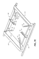
- FIG. 4 is a perspective view of a substrate transfer shuttle according to the present invention.
- FIG. 5 is a partial cross-sectional view of a processing chamber and substrate transfer shuttle according to the present invention.
- FIG. 6A is a transverse cross-sectional view of a processing island and shuttle according to an embodiment of the present invention.
- FIG. 6B is a transverse cross-sectional view of a processing island and shuttle according to an alternative embodiment of the present invention.
- FIGS. 7 A- 7 C are partial schematic cross-sectional views of a load lock chamber according to the present invention, showing a substrate in various stages of transfer from without to within a load lock chamber.
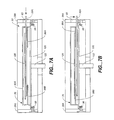
- FIGS. 7D and 7E are perspective views of alternative embodiments of a substrate transfer shuttle and a platen as may be located in a load lock chamber.
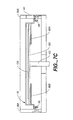
- FIGS. 8 A- 8 B are schematic cross-sectional views of a chamber according to the present invention, shown in different stages of transfer of a substrate between a shuttle and a susceptor in a processing chamber.
- FIG. 1 shows a processing island 42 of a fabrication system according to an embodiment of the present invention.
- Arrow 101 defines a direction pointing from “upstream” to “downstream” in the processing island.
- the island 42 includes a substrate heating load lock chamber 50 at a first end of the island and a substrate cooling load lock chamber 52 at a second end of the island, longitudinally opposite and downstream of the first end.
- the terms “heating” and “cooling” are not intended to be limiting. Rather, they are descriptive of exemplary features such chambers may possess.
- Each processing chamber 54 A- 54 C includes first and second gate valves 56 A- 56 C and 58 A- 58 C, respectively, at the first and second ends of each processing chamber (see also FIG. 3).
- the valve 56 A selectively seals the load lock chamber 50 from the processing chamber 54 A when closed and permits transfer of substrates through the valve between the load lock chamber 50 and the processing chamber 54 A when open.
- the valve 58 C selectively seals the load lock chamber 52 from the processing chamber 54 C in a closed condition and permits the transfer of substrates through the valve in an open condition.
- valves 58 A and 56 B seal the first processing chamber 54 A from the second processing chamber 54 B when closed and permit the transfer of substrates through the valves when open.
- valves 58 and 56 C selectively seal the second processing chamber 54 B from the third processing chamber 54 C in closed conditions and permit the transfer of substrates through the valves in open conditions.
- the pairs of valves 58 A, 56 B and 58 B, 56 C may be replaced with single valves although the illustrated configuration has advantages described below.
- An example of the type of valve which may be employed is described in above-mentioned U.S. patent application entitled “Isolation Valves”, [attorney docket number 2157 (226001)] filed on even date herewith, and incorporated by reference above.
- substrate is intended to broadly cover any object that is being processed in a process chamber, including flat panel displays, glass or ceramic plates, plastic sheets, or disks.
- the present invention is particularly applicable to large substrates such as glass plates having dimensions of 650 mm by 830 mm or even larger.
- the substrate is supported by support fingers.
- the support fingers may all be parallel, as shown in the embodiment of FIGS. 1, 4 and 7 D, or some may be angled as shown in the preferred embodiment of FIGS. 2 B- 2 C and 7 E.
- the short dimension of the substrate is generally parallel to the direction of movement within a processing island.
- FIGS. 1 and 3 show a substrate transfer shuttle in each of the load locks 50 and 52 .
- the load lock chambers 50 and 52 have respective gate or slit valves 60 and 62 positioned along one side of the island.
- the valves 60 and 62 (FIG. 3) selectively seal their associated load lock chambers from atmosphere in closed conditions and allow introduction or removal of substrates to or from the load lock chambers in open conditions.
- valves 56 A, 58 A, 56 B and 58 B are shown open, and valves 56 C and 58 C are shown closed.
- the substrates may be introduced through the valve 60 to the load lock chamber 50 which forms an entrance load lock chamber.
- the load lock chamber 50 With the load lock chamber 50 in a condition sealed from the atmosphere and process chamber 54 A, the load lock chamber may be pumped to vacuum and the substrate heated.
- the load lock system allows a staged vacuum to occur. That is, the process chamber vacuum need not be breached for substrates to be loaded and unloaded. Since the load locks are independently pumped-down prior to the opening of the valves separating them from the process chambers, the process chamber pumps need only evacuate a chamber that is already partially at vacuum. That is, they need only maintain process vacuum conditions. Such a capability is particularly important for, e.g., physical vapor deposition (PVD), which may often require the lowest pressure of any process.
- PVD physical vapor deposition
- Each load lock chamber may be multifunctional. Process steps such as heating, cooling, and descumming may be provided for in each load lock. Heating and cooling may be provided for by heating and cooling plates which may be moved into and out of thermal contact with the substrate. Typically, the load lock 50 may be used to heat and descum, while the load lock 52 may be used to cool. Ashing processes may also be provided for in the chambers. The substrate is then passed among the processing chambers 54 A- 54 C. In each processing chamber, a specific semiconductor process may be performed on the substrate. Ashing or descumming may also occur in a processing chamber. More details of a multifunctional load lock may be found in above-mentioned U.S.
- a processed substrate may be cooled in the cooling load lock chamber 52 , which forms an exit load lock chamber, and may also be brought up to atmospheric pressure. Thereafter, the substrate may be removed from the system through the valve 62 .
- Introduction and removal of substrates to and from the load lock chambers 50 and 52 may be performed by robots 64 A and 64 B, respectively (see FIG. 1). Alternatively, just one robot may be employed, operating on a track or conveyor, to introduce or remove substrates.
- Each robot includes an end effector in the form of a lifting fork 66 A, 66 B at the distal end of an arm 68 A, 68 B. At its proximal end, each arm 68 A, 68 B is coupled to an associated vertical linear actuator (not shown) to permit the arm and lifting fork to be raised and lowered.
- the top of the lifting forks 66 A and 66 B may have thereon a number of supports 154 to support a substrate 126 on top of the fork 66 A, 66 B.
- the robot 64 A can retrieve and return substrates to and from substrate holding cassettes.
- the robot 64 A may load a substrate into heating load lock chamber 50 of the island through the gate or slit valve 60 (FIG. 3).
- Robot 64 B operates in a similar fashion to robot 64 A. More details of the robots may be found in U.S. patent application entitled “Modular Substrate Processing System,” filed on even date herewith, and incorporated by reference above.
- the fork 66 A may be inserted beneath a substrate in a cassette or on a shuttle in a load lock chamber.
- the fork design is such that the same fork may be used for either, facilitating considerable advantage in incorporating the system into existing product lines.
- the upper surface of the fork 66 A or, more particularly, supports 154 (see FIGS. 2A and 2C) along the upper surface of the fork tines engage the lower surface of the substrate.
- the fork 66 A lifts the substrate out of engagement with the cassette or shuttle.
- a z-rotary actuator of the robot 64 A is caused to rotate the loading end effector 66 A 180° so that the substrate may be introduced into load lock heating chamber 50 through the slit valve 60 . Fine adjustments may be made by the z-linear actuator to adjust the height of the substrate so that the substrate may enter through the slit valve 60 (FIG. 3) unimpeded.
- the slit valve 60 is opened and the substrate is moved by a y-linear actuator in the y-direction. This movement loads the substrate into load lock heating chamber 50 where it is lowered onto the shuttle 70 using the z-linear actuator. The empty end effector 66 A may then be withdrawn from the chamber. Slit valve 60 is then closed and the heating and evacuation process begun.
- Transfer shuttle 70 and 72 Associated with each load lock chamber 50 and 52 is a transfer shuttle 70 and 72 , respectively, configured for transporting substrates between chambers.
- the first and second shuttles 70 and 72 are positioned in the heating and cooling load lock chambers during introduction of a substrate to the heating load lock chamber 50 and removal of a substrate from the cooling load lock chamber 52 , respectively.
- Transfer shuttles 70 and 72 may be made of stainless steel, invar, ceramics or any other similar material. Invar may be preferable as it has a low coefficient of thermal expansion.
- the load lock chambers 50 and 52 may be equipped with maintenance windows or slits 152 (FIG. 1). These windows 152 allow the removal of the components from the load locks for maintenance or repair. During such a maintenance situation, both shuttle and chamber components may be repaired.
- each shuttle 70 , 72 has a first end 31 A facing from the associated load lock chamber toward the adjacent processing chamber and a second end 31 B opposite the first end.
- Each shuttle further has first and second sides 32 A and 32 B, respectively.
- the shuttles may be mirror images of each other and are positioned facing each other.
- each shuttle includes first and second side rails 74 A and 74 B along the respective first and second sides of the shuttle. Both side rails extend substantially between the first and second ends of the shuttle. The side rails are parallel to and spaced-apart from each other.
- Each side rail includes a generally flat horizontal strip 75 . Along an outboard portion of the underside of each strip, the rail bears a rack 76 . An outboard portion 77 of the underside of each rack bears angled teeth 33 (the shape of the teeth are not shown). An inboard portion 78 of the underside of each rack is flat for engaging a number of guide rollers as described below.
- First and second cross-members 80 A and 80 B respectively, proximate the first and second ends of the shuttle, structurally connect the first and second side rails to each other.
- Each cross-member is slightly recessed from the associated end of the shuttle, and each cross-member includes a flat central horizontally-extending strip 82 .
- First ( 83 A and 84 A) and second ( 83 B and 84 B) legs depend from first and second ends of the strip and connect such ends to the first and second side rails, respectively.
- An “X” indicates the location of the center of the substrate. This X location should roughly correspond with the center of the processing chamber, as measured in a horizontal plane, for optimum processing of the substrate.
- Substrate support fingers 86 A, 88 A, 86 B and 88 B extend inwardly from the associated first and second side rails, respectively.
- each support finger has a proximal portion 90 extending upwardly from the associated side rail 75 and a distal portion 92 extending horizontally inwardly from the proximal portion and ending at a tip.
- the upper surface of each finger bears a pad 94 for supporting a substrate held by the shuttle.
- the pads 94 may advantageously be made of a material such as a 30 ceramic, stainless steel, quartz, or other such materials.
- substrates would be removed from a heating chamber by a vacuum robot which would then transport the substrate to a processing chamber, resulting in cooling of the substrate.
- a solution was to overheat the substrate, intending for it to cool when transported.
- the substrate transfer shuttle 70 moves the substrate into a processing chamber directly from the heating chamber.
- the requirement for overheating the substrate is alleviated if not eliminated.
- FIG. 5 also shows inner and outer chamber walls 38 B and 38 A. respectively.
- a slot 38 C is located in inner wall 38 B to allow the flat rail 75 of the shuttle to extend into the opening in wall 38 B to engage rollers 98 . In this way, contamination caused by guide rollers 98 may be minimized. Further, the process performed within the chamber is kept separate from the mechanical components causing the shuttle movement.
- the width of the lifting forks 66 A, 66 B may be close to but less than the distance between the two exterior support fingers 88 A and 88 B along one side of the shuttle 70 .
- the central cut-out section of the fork should be large enough such that it does not interfere with the central support finger 86 A.
- the width of the fork may be larger.
- each support finger there are three support fingers associated with each side rail: a central support finger 86 A, 86 B and two lateral diagonal support fingers 88 A, 88 B.
- Each support finger preferably extends about 15-30% of a dimension such as the length or the diagonal of the substrate in order to adequately support the substrate, and even more preferably about 22% of the length approximately (0.22 l) of the substrate. Referring to FIG. 2D, such placement ensures that when a substrate 126 is heated, bowing caused by the substrate flexibility results in a minimal volume swept out by the bowing substrate as it moves along the flow path.
- the height of pads 94 is also important.
- the height should be chosen such that when the heated substrate bows, the edges of the substrate do not make contact with the fingers directly. The importance of this aspect to the quality of the resulting substrate depends on the process requirements.
- Another advantage of such a configuration is that the same support fingers may be used to support several different sizes of substrates. Moreover, the location of the support fingers is adjustable to accommodate various substrate sizes. The location of the pads 94 is also variable to accommodate different substrate sizes. It should also be noted that while a shuttle servicing the load lock chamber 50 must be designed to withstand high temperatures, the shuttle servicing load lock chamber 52 has somewhat more forgiving requirements, as it is less inclined to see the maximum processing temperatures.
- FIGS. 1, 4, and 7 D show an alternate embodiment in which lateral support fingers 88 A and 88 B are not diagonal but rather are parallel to support fingers 86 A and 86 B. Other angled fingers may be used, so long as they adequately support the substrate.
- each shuttle may accept substrates from two directions, each 90° away from each other.
- the shuttle may accept and release substrates in a direction perpendicular to the side rails.
- the shuttle may accept and release substrates in a direction parallel to the side rails.
- a plurality of stoppers 201 may be provided, as shown in FIGS. 2 B- 2 C, 4 - 5 and 8 A- 8 B, to ensure accurate placement of the substrate on the support fingers and to prevent accidental shifting of the substrate on the shuttle during transport. Substrates may also be centered on the fingers by using the plurality of stoppers 201 .
- These stoppers 201 may have the general shape of an inverted truncated cone, such as an inverted frustum.
- each load lock chamber and each processing chamber includes a number of pairs of guide rollers 98 (e.g., two rollers per side of the processing chambers and three rollers per side of the load locks) positioned so as to provide support and guidance to one or both shuttle(s) as such shuttle(s) pass through the chambers.
- the guide rollers 98 may be Teflon®-coated aluminum, Vespel®, or any other such material that is not particulate-generating and is soft for dampening vibrations. Alternatively, suspensions may be employed to provide a smooth movement.
- the guide rollers are all at substantially even level and define a fixed path along which the shuttles may move back and forth.
- the guide rollers are configured to engage the flat inboard portion 78 of the underside of each rack as a shuttle passes over the guide rollers so as to position and orient the shuttle and provide smooth shuttle movement along the predefined path.
- each of the processing chambers 54 A- 54 C and the load lock chambers are chamber isolation valves whose housings may each include a shuttle drive mechanism 100 .
- Such a configuration reduces particulate contamination within the processing chambers as is often required, e.g., in TFT formation.
- Such an island layout also facilitates a high degree of modularity because each chamber has a similar structure and is interchangeable.
- the length of the shuttles used is generally longer, as described in more detail below, than the associated distance between the driving mechanisms.
- the overall length of the shuttles used is generally longer than the length of any process chambers through which they pass.
- each drive mechanism 100 includes a motor 102 external to the interior cavity of the associated chamber and coupled to a drive shaft assembly 104 extending into and within the interior of the load lock or valve housing.
- the inner chamber wall 38 B is not shown for clarity.
- the drive shaft assembly 104 may employ vacuum-compatible rotary feedthroughs.
- the drive shaft assembly carries first and second pinion ears 106 A and 106 B adjacent first and second sides of the associated chamber, and first and second guide rollers 108 A and 108 B immediately inboard of the first and second pinion ears, respectively.
- the drive mechanism 100 includes an encoder 110 which provides input to a control system 111 responsive to rotation of the associated drive shaft assembly.
- the control system 111 may be connected to any and each of the various chambers for controlling their operations as well as the operation of any handling or processing equipment external to the island.
- the control system may comprise a user-programmable computer or other controller incorporating appropriate software or firmware.
- FIG. 6B shows an alternate configuration in which no drive shaft is employed.
- the shuttle is driven from one side only, and the motor may drive a pinion gear 106 without using the drive shaft assembly 104 .
- Laterally positioned guide rollers 203 may be used in addition to guide roller 108 A and 108 B to ensure that the shuttle moves in a straight horizontal direction and is not caused to misalign due to its only being driven on one side.
- Rollers 203 are positioned on each side of a guide rail 112 in order to keep the shuttle 70 moving in a straight and controlled direction.
- the guide rollers be inboard of the pinion gears.
- the guide rollers may be outboard of the pinion gears or the relative position may be different on each side of a line of chambers.
- rollers may be placed on the substrate transfer shuttle and a smooth flat ridge may be located along each side of a line of chambers to support the shuttle guide rollers.
- FIGS. 7 A- 7 E the placement of a substrate into a load lock chamber is described with respect to FIGS. 7 A- 7 E.
- the support on which the substrate is placed is referred to as a platen.
- the platen has slots through which fingers of the shuttle may move when transferring substrates.
- FIGS. 8 A- 8 B the support on which the substrate is placed.
- the susceptor has passages with extendable “T”-shaped pins for use in transferring substrates, as described below.
- platen and susceptor are used herein for clarity.
- the susceptor in the processing chamber may be equally well termed a “platen” and the platen in the load lock may be equally well termed a “susceptor.”
- each load lock chamber 50 , 52 (only chamber 50 is shown) includes a platen 120 for supporting a substrate during heating or cooling prior to or after processing.
- a pedestal 122 supports the platen 120 and is raisable and lowerable to raise and lower the platen 120 between a first or retracted position and a second or extended position.
- the platen 120 is generally rectangular and slightly larger than the plan area of the substrate and has a plurality of channels 124 (FIGS. 7D and 7E) extending inwardly from the opposite sides of the platen.
- the channels are configured so as to accommodate the fingers 86 A, 86 B, 88 A, and 88 B of a shuttle 70 when the platen 120 is raised or lowered through such a shuttle 70 as described below.
- the load lock chamber 50 is vacant and is shielded from the adjacent chamber 54 A by the valve 56 A.
- the load lock chamber 50 is vented to atmosphere and its slit valve 60 is opened to permit introduction of a substrate to the island.
- a substrate 126 is loaded into the load lock chamber 50 by the robot end effector 66 A.
- the end effector and substrate are inserted via a horizontal (y-direction) movement into the chamber 50 at a height at which the underside of the end effector 66 A is above the fingers 88 A. 88 B of the shuttle 70 .
- the end effector 66 A carrying the substrate 126 is stopped with the substrate 126 located centrally above the platen and then lowered.
- the end effector 66 A reaches a second height shown in FIG. 7B.
- the end effector passes below the fingers of the shuttle, with e.g., one tine of the end effector 66 A passing on each side of the central fingers 86 A and 86 B and just inboard of adjacent lateral support fingers 88 A, 88 B.
- the pads 94 will engage the underside of the substrate 126 causing the shuttle 70 to acquire the substrate 126 from the end effector 66 A.
- the end effector 66 A reaches the position shown in FIG. 7B, it may be withdrawn from the load lock chamber 50 via horizontal translation. Once the end effector 66 A is withdrawn, the valve 60 may be closed and the chamber 50 pumped down.
- the platen 120 may then be raised from its initial height in FIG. 7A to a raised height shown in FIG. 7C.
- the platen 120 passes around the fingers of the shuttle, each finger being accommodated by an associated one of the channels 124 (see FIGS. 7D and 7E).
- the substrate 126 When the upper surface of the platen 120 contacts the underside of the substrate 126 , it raises the substrate 126 off of the fingers (more particularly, pads 94 ) to acquire the substrate 126 from the shuttle 70 .
- the substrate 126 With the substrate 126 held by the platen 120 as shown in FIG. 7C, the substrate 126 may be heated or otherwise prepared to ready it for processing.
- a multiple substrate cassette (not shown) may also be employed in the load lock chambers 50 or 52 .
- the load lock chamber 50 may be used as a buffer for storage of substrates prior to processing. More details of a multiple substrate cassette are provided in above-mentioned U.S. patent application for an “In-Situ Substrate Transfer Shuttle,” [attorney docket number 2703(266001)], filed on even date herewith, and incorporated by reference above.
- the platen 120 may be lowered and returned to the position of FIG. 7B, with the shuttle 70 reacquiring the substrate 126 from the platen 120 in the process.
- the valve 56 A may be opened to establish communication between the load lock chamber 50 and the processing chamber 54 A.
- the pinion gears of the drive mechanism 100 of the load lock 50 are engaged to the racks of the shuttle 70 adjacent the downstream ends of the shuttle's rails.
- the motor of the drive mechanism may be powered so as to move the shuttle downstream through the valve 56 A and into the first processing chamber.
- each processing chamber includes a susceptor 130 for supporting a substrate 126 during processing.
- the plan area of the susceptor 130 is slightly larger than that of the substrate 126 and the susceptor 130 has an upper surface 132 configured to contact substantially the entire underside of the substrate 126 during processing.
- the upper surface 132 of the susceptor 130 is continuous except for interruptions caused by the presence of passages for the lift pins 134 which may extend through the susceptor 130 from below.
- the susceptor 130 has a central pedestal 136 which may be raised and lowered to raise and lower the susceptor 130 .
- the lift pins 134 are secured at their lower ends to a pin plate 138 .
- the pins and pin plate are generally raised and lowered by an outer shaft 139 which surrounds the central pedestal 136 .
- lift pins 134 and pin plate 138 move independently from susceptor 130 .
- Lift pins 134 support a substrate when they are in an extended position. As the lift pins are retracted, the substrate is lowered onto the susceptor 130 .
- susceptor 130 is caused to rise, the lift pins are caused to retract to a position below the surface 132 of the susceptor 130 .
- the pins may pass below surface 132 by virtue of a counterbore located within surface 132 .
- This embodiment allows a convenient way of transferring support of the substrate from the pins 134 to the susceptor 130 as the susceptor 130 is raised. More details of this pin system may be found in U.S. patent application Ser. No. 08/950,277, entitled “A Vacuum Processing System Having Improved Substrate Heating and Cooling”, filed Oct. 14, 1997, assigned to the assignee of the present invention and incorporated herein by reference.
- each chamber includes six lift pins 134 arranged in pairs extending from upstream to downstream in the chamber.
- the lift pins 134 may also be advantageously located at about 15-30% of the dimension of the substrate 126 and more preferably about 22% of the width of the substrate 126 . They may even more preferably be located just inside of the distal end of the pad 94 location. While it would be preferable to have both the pins 134 and the pads 94 at the 22% point, such placement would not allow the same to pass around each other. Thus, it may be advantageous to have the pins and pads close to each other, but to have the pins just nearer to the centerline of the substrate that the pads. In this way, relative movement can be accomplished without contact.
- the lift pins 134 may have the general cross-sectional shape of a “T”.
- a corresponding counterbore as mentioned above, may be placed in the susceptor 130 around the lift pin holes so that the lift pins, when fully retracted, are below the level of the top surface 132 of the susceptor 130 .
- the substrate then does not contact the lift pins in their retracted positions. In this way, the lift pins have a minimal thermal signature.
- the lift pins 134 , and their passages through the susceptor 130 do not significantly affect the even distribution of temperature across the susceptor 130 and thus across the substrate 126 .
- the high process requirements with regard to uniformity of temperature for, e.g., TFT formation may be advantageously achieved.
- the substrate 126 and shuttle fingers 86 A, 86 B, 88 A, and 88 B pass over the susceptor 130 which is at a first height as shown in FIG. 8A.
- the lift pins 134 may be in an extended position relative to the susceptor 130 (as shown in FIGS. 8A and 8B) or may be in a retracted position.
- the susceptor 130 and/or lift pins 134 are raised.
- the pins As lift pin plate 138 , lift pins 134 , and/or the susceptor 130 are raised, the pins (stationary and in the extended position) contact the underside of the substrate 126 (FIG. 8A) and raise the substrate 126 out of the engagement with the shuttle 70 (FIG. 8B). With the substrate 126 in this intermediate position, the shuttle 70 may be withdrawn from the processing chamber 54 A, with the fingers 86 A, 86 B, 88 A, and 88 B passing around the lift pins 134 and between the substrate 126 and the susceptor 130 , at least one of the cross members 80 A, 80 B of the shuttle 70 passing over the substrate 126 .
- the shuttle 70 may be withdrawn to the load lock chamber 50 or may be driven into the second processing chamber 54 B or therebeyond, e.g., to service other substrates by transporting the same to other chambers, etc. Once, however, the shuttle 70 is out of the chamber 54 A, the chamber 54 A may be sealed by shutting the valve 56 A (and valves 58 A and 56 B if these have been opened). The pins 134 may then be lowered relative to the susceptor 130 to place the substrate atop the susceptor 130 .
- valve 56 A may be opened, establishing communication between the load lock chamber 50 and the processing chamber 54 A.
- valves 58 A and 56 B may also be opened if the shuttle has been sent downstream.
- the lift pins 134 and pin plate 138 may then be raised, thus raising the substrate above the susceptor 130 such that the substrate is supported on the lift pins.
- the shuttle 70 is returned to the processing chamber 54 A in a similar fashion as when delivering the substrate 126 to the processing chamber 54 A.
- the fingers 86 A, 86 B, 88 A, and 88 B pass between the substrate 126 and the susceptor 130 , passing around the lift pins 134 .
- the cross-member 80 A passes over the substrate 126 .
- the susceptor 130 and/or pins 134 may be lowered to the position of FIG. 8A, during which the fingers 86 A, 86 B, 88 A, and 88 B acquire the substrate 126 from the pins 134 .
- the substrate 126 may be delivered to the second processing chamber 54 B through valves 58 A and 56 B.
- the steps of this transfer may be similar to the steps involved in the transfer from the load lock chamber 50 to the first processing chamber 54 A.
- the substrate 126 may be transferred to the third processing chamber 54 C. This may be done with either of the shuttles 70 and 72 .
- the substrate may be withdrawn from the third processing chamber 54 C into the load lock chamber 52 by the shuttle 72 via a reverse of steps similar to those performed with the shuttle 70 in transferring the substrate from the load lock chamber 50 to the first processing chamber 54 A.
- the extraction of the substrate 126 from the cooling load lock chamber 52 by the robot end effector 68 B may be performed by substantially reversing the steps used with the robot end effector 66 A in introducing the substrate 126 to the heating load lock chamber 50 .
- lift pins 134 provide another advantage.
- lift pins 134 may be used to elevate the substrate 126 above the heated or cooled susceptor 130 . Such elevation may be maintained for as long as necessary to bring the substrate temperature to a desired level. For example, if the substrate 126 is to be cooled, but the susceptor 130 is at a high temperature, maintaining the pins 134 in an elevated position may be useful for cooling the substrate 126 .
- alcoves or compartments 148 in the end walls of the entrance and exit load locks are provided to accommodate an associated end of a side rail of the shuttles 70 and 72 , respectively.
- the side rail's ends are received and accommodated by such compartments.
- the rails may be generally longer than the length of process chambers 54 A- 54 C. This allows the volume of the load locks to be correspondingly minimized. Such minimization is advantageous for, e.g., accomplishing a more convenient pump-down.
- Reduced chamber volume facilitates faster and more economical pumping down of chambers, including reducing the capacity requirements for any vacuum pumps. Additionally, the introduction of process or inert gases is facilitated with a reduced consumption of such gases. Heating and cooling may be more easily facilitated. Process uniformity may be increased, for example, by providing a more uniform plasma in the absence of voids or cavities.
- each chamber with two valves 56 A- 56 C, 58 A- 58 C is that this allows each such valve to be located substantially adjacent the susceptor of the associated chamber.
- the drive mechanism 100 of each processing chamber may be located in the outside of the cavity defined by the valve housing. This significantly reduces contamination of the chambers due to the drive mechanisms.
- the system is configured so that certain components may be serviced or replaced with minimal disruption of the system or contamination of the system chambers.
- the drive motors 102 and encoders 110 may be serviced or replaced from outside the island without risk of contamination. If a drive shaft 104 or any of its associated components needs to be serviced or replaced, such operation may be performed with the valves on either side of the drive mechanism closed. Thus, the interiors of the adjacent chambers will not become contaminated from such action. Any contamination will be limited to the space between the valves immediately surrounding the drive mechanism which may be more readily cleaned than the interior of the adjacent chambers.
Abstract
The present invention provides an apparatus and method for substrate transport. In systems according to the invention, at least a first and second chamber are provided. The first chamber may be a load lock and the second chamber a processing chamber. A substrate transfer shuttle is provided and is moveable along a linear path defined by guide rollers between one position in the first chamber and another position in the second chamber. In this way, the substrate may be transferred, in both a forward and a reverse direction, between the first chamber and the second chamber. The substrate transfer shuttle is structured so that a substrate may be removed therefrom by moving a support in one of the chambers from a lowered position to an intermediate position, after which the substrate transfer shuttle may be removed from the chamber.
Description
- The present application is related to co-pending U.S. patent application Ser. No. 08/946,922, entitled “MODULAR CLUSTER PROCESSING SYSTEM,” filed Oct. 8, 1997. The present application is also related to the following U.S. patent applications which are being filed concurrently with this application: (1) “Method and Apparatus for Substrate Transfer and Processing” [attorney docket 2519/US/AKT (05542/235001)]; (2) “Multi-Function Chamber For A Substrate Processing System,” [attorney docket 2712/US/AKT (05542/268001)]; (3) “An Automated Substrate Processing System,” [attorney docket 2429/US/AKT (05542/245001)]; (4) “Substrate Transfer Shuttle Having a Magnetic Drive,” [attorney docket 2638/US/AKT (05542/264001)]; (5) “In-Situ Substrate Transfer Shuttle,” [attorney docket 2703/US/AKT (05542/266001)]; and (6) Modular Substrate Processing System,” [attorney docket 2311/US/AKT (05542/233001)].
- The foregoing patent applications, which are assigned to the assignee of the present application, are incorporated herein by reference.
- The invention relates to substrate processing, and more particularly to transferring substrates to and from processing chambers.
- Glass substrates are being used for applications such as active matrix televisions and computer displays, among others. A large glass substrate can form multiple display monitors, each of which may contain more than a million thin film transistors.
- The processing of large glass substrates often involves the performance of multiple sequential steps, including, for example, the performance of chemical vapor deposition (CVD) processes, physical vapor deposition (PVD) processes, or etch processes. Systems for processing glass substrates can include one or more process chambers for performing those processes.
- The glass substrates can have dimensions, for example, of 550 mm by 650 mm. The trend is toward even larger substrate sizes, such as 650 mm by 830 mm and larger, to allow more displays to be formed on the substrate or to allow larger displays to be produced. The larger sizes place even greater demands on the capabilities of the processing systems.
- Some of the basic processing techniques for depositing thin films on the large glass substrates are generally similar to those used, for example, in the processing of semiconductor wafers. Despite some of the similarities, however, a number of difficulties have been encountered in the processing of large glass substrates that cannot be overcome in a practical way and cost effectively by using techniques currently employed for semiconductor wafers and smaller glass substrates.
- For example, efficient production line processing requires rapid movement of the glass substrates from one work station to another, and between vacuum environments and atmospheric environments. The large size and shape of the glass substrates makes it difficult to transfer them from one position in the processing system to another. As a result, cluster tools suitable for vacuum processing of semiconductor wafers and smaller glass substrates, such as substrates up to 550 mm by 650 mm, are not well suited for the similar processing of larger glass substrates, such as 650 mm by 830 mm and above. Moreover, cluster tools require a relatively large floor space.
- One way to improve such processing tools is disclosed in U.S. patent application Ser. No. 08/946,922, entitled “MODULAR CLOSTER PROCESSING SYSTEM.” assigned to Applied Komatsu Technologies, Inc. of Santa Clara, Calif., and incorporated above by reference. The use of a modular processing system is disclosed, with substrate movement exterior of processing islands performed by conveyors or robots on tracks. Substrate movement interior of processing islands is performed by a substrate transporter. In this type of system, the transporter may move a substrate into or out of a processing chamber, after which the transporter may stay resident in either load lock.
- Similarly, chamber configurations designed for the processing of relatively small semiconductor wafers are not particularly suited for the processing of these larger glass substrates. The chambers must include apertures of sufficient size to permit the large substrates to enter or exit the chamber. Moreover, processing substrates in the process chambers typically must be performed in a vacuum or under low pressure. Movement of glass substrates between processing chambers, thus, requires the use of valve mechanisms which are capable of closing the especially wide apertures to provide vacuum-tight seals and which also must minimize contamination.
- Furthermore, relatively few defects can cause an entire monitor formed on the substrate to be rejected. Therefore, reducing the occurrence of defects in the glass substrate when it is transferred from one position to another is critical. Similarly, misalignment of the substrate as it is transferred and positioned within the processing system can cause the process uniformity to be compromised to the extent that one edge of the glass substrate is electrically non-functional once the glass has been formed into a display. If the misalignment is severe enough, it even may cause the substrate to strike structures and break inside the vacuum chamber.
- Other problems associated with the processing of large glass substrates arise due to their unique thermal properties. For example, the relatively low thermal conductivity of glass makes it more difficult to heat or cool the substrate uniformly. In particular, thermal losses near the edges of any large-area, thin substrate tend to be greater than near the center of the substrate, resulting in a non-uniform temperature gradient across the substrate. The thermal properties of the glass substrate combined with its size, therefore, makes it more difficult to obtain uniform characteristics for the electronic components formed on different portions of the surface of a processed substrate. Moreover, heating or cooling the substrates quickly and uniformly is more difficult as a consequence of its poor thermal conductivity, thereby reducing the ability of the system to achieve a high throughput.
- As noted above, efficient production line processing requires rapid movement of the glass substrates from one work station to another. Other requirements include a structure that can firmly support the glass substrate during transfer and that can transport the glass substrate to all areas of a work station or processing island.
- The present invention allows large glass substrates to be moved within a processing station and from one processing station to another. In systems according to the invention, at least a first and second chamber are provided. Typically, the first chamber is a load lock and the second chamber is a processing chamber. The processing chamber may serve as an inspection station, a CVD chamber, a PECVD chamber, a PVD chamber, a post-anneal chamber, a cleaning chamber, a descumming chamber, an etch chamber or a combination of such chambers. The load lock may be employed to heat or cool the substrate. Two load locks may be employed, one to perform heating and the other to perform cooling. The load locks each include a platen for supporting the substrate.
- A substrate transfer shuttle is used to move substrate along a guide path defined by, e.g., guide rollers.
- The substrate transfer shuttle is moveable along a linear path defined by guide rollers between one position in the first chamber and another position in the second chamber. In this way, the substrate may be transferred, in both a forward and a reverse direction, between the first chamber and the second chamber. The substrate transfer shuttle is structured so that a substrate may be removed therefrom by moving the platen from a lowered position to an intermediate position, after which the substrate transfer shuttle may be removed from the processing chamber. The substrate transfer shuttle includes first and second longitudinal side rails at respective first and second sides thereof. The shuttle also includes first and second pluralities of substrate support elements extending inwardly from the first longitudinal side rail and positioned to pass below the substrate when the substrate transfer shuttle is removed from the processing chamber. The substrate support elements extend about 15-30% of a dimension of the substrate, and more particularly about 22% of the width of the substrate. Drive mechanisms are employed that engage with at least the first longitudinal side rail to move the substrate transfer shuttle along at least portions of the shuttle path.
- Implementations of the invention may include one or more of the following. A valve may be employed to selectively seal the first chamber from the second chamber when closed and to permit transfer of the substrate between the first chamber and the second chamber through the valve when open. Multiple shuttles may be employed for convenience in a particular process. Further, multiple intermediate chambers may be located between the first and second chambers.
- The susceptor in the processing chamber includes a plurality of lift pins which are movable through holes in the susceptor and which support the substrate above the susceptor.
- Steps of the method include positioning a substrate onto a substrate transfer shuttle in a load lock, and moving the substrate transfer shuttle from the load lock into a processing chamber along a first portion of a path. The substrate is removed from the substrate transfer shuttle and positioned it on a platen in the processing chamber. The substrate transfer shuttle is then removed from the processing chamber and the substrate is processed. Following processing, the substrate transfer shuttle is moved into the processing chamber and the substrate is positioned thereon. The substrate transfer shuttle and the substrate are moved into the load lock, and the substrate is removed from the substrate transfer shuttle.
- Advantages of the invention include one or more of the following. The invention eliminates unnecessary substrate movement in a semiconductor processing system. For example, the substrate may be transferred horizontally except for loading and unloading on the susceptor. The invention also eliminates more expensive and cumbersome vacuum robots and transfer chamber systems. The invention allows removal of a substrate transfer shuttle during processing, reducing contamination.
- The details of one or more embodiments of the invention are set forth in the accompanying drawings and the description below. Other features, objects, and advantages of the invention will be apparent from the description and drawings, and from the claims.
- FIG. 1 is a top plan schematic view of a processing island of a system according to the present invention.
- FIG. 1A is a side schematic view of a section of a load lock emplying alcoves.
- FIGS. 2A-2C are top plan views of a shuttle and lifting fork according to the present invention.
- FIG. 2D is a side view showing a heated bowing glass substrate supported on support fingers.
- FIG. 3 is a side schematic view of a processing island of a system according to the present invention.
- FIG. 4 is a perspective view of a substrate transfer shuttle according to the present invention.
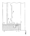
- FIG. 5 is a partial cross-sectional view of a processing chamber and substrate transfer shuttle according to the present invention.
- FIG. 6A is a transverse cross-sectional view of a processing island and shuttle according to an embodiment of the present invention.
- FIG. 6B is a transverse cross-sectional view of a processing island and shuttle according to an alternative embodiment of the present invention.
- FIGS. 7A-7C are partial schematic cross-sectional views of a load lock chamber according to the present invention, showing a substrate in various stages of transfer from without to within a load lock chamber.
- FIGS. 7D and 7E are perspective views of alternative embodiments of a substrate transfer shuttle and a platen as may be located in a load lock chamber.
- FIGS. 8A-8B are schematic cross-sectional views of a chamber according to the present invention, shown in different stages of transfer of a substrate between a shuttle and a susceptor in a processing chamber.
- Like reference numbers and designations in the various drawings indicate like elements.
- FIG. 1 shows a
processing island 42 of a fabrication system according to an embodiment of the present invention.Arrow 101 defines a direction pointing from “upstream” to “downstream” in the processing island. Theisland 42 includes a substrate heatingload lock chamber 50 at a first end of the island and a substrate coolingload lock chamber 52 at a second end of the island, longitudinally opposite and downstream of the first end. Of course, the terms “heating” and “cooling” are not intended to be limiting. Rather, they are descriptive of exemplary features such chambers may possess. - Between the
load lock chambers processing chambers 54A-54C, which are connected in series between the load lock chambers. Eachprocessing chamber 54A-54C includes first andsecond gate valves 56A-56C and 58A-58C, respectively, at the first and second ends of each processing chamber (see also FIG. 3). Thevalve 56A selectively seals theload lock chamber 50 from theprocessing chamber 54A when closed and permits transfer of substrates through the valve between theload lock chamber 50 and theprocessing chamber 54A when open. Similarly, thevalve 58C selectively seals theload lock chamber 52 from theprocessing chamber 54C in a closed condition and permits the transfer of substrates through the valve in an open condition. Thevalves first processing chamber 54A from thesecond processing chamber 54B when closed and permit the transfer of substrates through the valves when open. Likewise, thevalves 58 and 56C selectively seal thesecond processing chamber 54B from thethird processing chamber 54C in closed conditions and permit the transfer of substrates through the valves in open conditions. The pairs ofvalves - This detailed description describes an embodiment in which a glass substrate is used. The term “substrate” is intended to broadly cover any object that is being processed in a process chamber, including flat panel displays, glass or ceramic plates, plastic sheets, or disks. The present invention is particularly applicable to large substrates such as glass plates having dimensions of 650 mm by 830 mm or even larger.
- In this system, the substrate is supported by support fingers. The support fingers may all be parallel, as shown in the embodiment of FIGS. 1, 4 and 7D, or some may be angled as shown in the preferred embodiment of FIGS. 2B-2C and 7E. In the described embodiments, the short dimension of the substrate is generally parallel to the direction of movement within a processing island.
- FIGS. 1 and 3 show a substrate transfer shuttle in each of the load locks 50 and 52. As shown in FIG. 3, the
load lock chambers valves valves 60 and 62 (FIG. 3) selectively seal their associated load lock chambers from atmosphere in closed conditions and allow introduction or removal of substrates to or from the load lock chambers in open conditions. In this figure,valves valves - The substrates may be introduced through the
valve 60 to theload lock chamber 50 which forms an entrance load lock chamber. With theload lock chamber 50 in a condition sealed from the atmosphere andprocess chamber 54A, the load lock chamber may be pumped to vacuum and the substrate heated. - The load lock system allows a staged vacuum to occur. That is, the process chamber vacuum need not be breached for substrates to be loaded and unloaded. Since the load locks are independently pumped-down prior to the opening of the valves separating them from the process chambers, the process chamber pumps need only evacuate a chamber that is already partially at vacuum. That is, they need only maintain process vacuum conditions. Such a capability is particularly important for, e.g., physical vapor deposition (PVD), which may often require the lowest pressure of any process.
- Each load lock chamber may be multifunctional. Process steps such as heating, cooling, and descumming may be provided for in each load lock. Heating and cooling may be provided for by heating and cooling plates which may be moved into and out of thermal contact with the substrate. Typically, the
load lock 50 may be used to heat and descum, while theload lock 52 may be used to cool. Ashing processes may also be provided for in the chambers. The substrate is then passed among theprocessing chambers 54A-54C. In each processing chamber, a specific semiconductor process may be performed on the substrate. Ashing or descumming may also occur in a processing chamber. More details of a multifunctional load lock may be found in above-mentioned U.S. patent application entitled “Multi-Function Chamber for a Substrate Processing System,” [attorney docket number 2712 (268001)] filed on even date herewith, and incorporated by reference above. - A processed substrate may be cooled in the cooling
load lock chamber 52, which forms an exit load lock chamber, and may also be brought up to atmospheric pressure. Thereafter, the substrate may be removed from the system through thevalve 62. Introduction and removal of substrates to and from theload lock chambers robots - Each robot includes an end effector in the form of a lifting
fork arm arm forks supports 154 to support asubstrate 126 on top of thefork - The
robot 64A, for instance, can retrieve and return substrates to and from substrate holding cassettes. In a first loading position, therobot 64A may load a substrate into heatingload lock chamber 50 of the island through the gate or slit valve 60 (FIG. 3).Robot 64B operates in a similar fashion torobot 64A. More details of the robots may be found in U.S. patent application entitled “Modular Substrate Processing System,” filed on even date herewith, and incorporated by reference above. In a first or lowered position, thefork 66A may be inserted beneath a substrate in a cassette or on a shuttle in a load lock chamber. The fork design is such that the same fork may be used for either, facilitating considerable advantage in incorporating the system into existing product lines. When raised to an intermediate position, the upper surface of thefork 66A or, more particularly, supports 154 (see FIGS. 2A and 2C) along the upper surface of the fork tines, engage the lower surface of the substrate. When further elevated to a second or raised position, thefork 66A lifts the substrate out of engagement with the cassette or shuttle. - During loading, a z-rotary actuator of the
robot 64A is caused to rotate theloading end effector 66A 180° so that the substrate may be introduced into loadlock heating chamber 50 through theslit valve 60. Fine adjustments may be made by the z-linear actuator to adjust the height of the substrate so that the substrate may enter through the slit valve 60 (FIG. 3) unimpeded. During substrate loading, theslit valve 60 is opened and the substrate is moved by a y-linear actuator in the y-direction. This movement loads the substrate into loadlock heating chamber 50 where it is lowered onto theshuttle 70 using the z-linear actuator. Theempty end effector 66A may then be withdrawn from the chamber.Slit valve 60 is then closed and the heating and evacuation process begun. - Associated with each
load lock chamber transfer shuttle second shuttles load lock chamber 50 and removal of a substrate from the coolingload lock chamber 52, respectively. Transfer shuttles 70 and 72 may be made of stainless steel, invar, ceramics or any other similar material. Invar may be preferable as it has a low coefficient of thermal expansion. - The
load lock chambers windows 152 allow the removal of the components from the load locks for maintenance or repair. During such a maintenance situation, both shuttle and chamber components may be repaired. - Referring to FIGS. 1, 2B, 4, and 7D-7E, each
shuttle first end 31A facing from the associated load lock chamber toward the adjacent processing chamber and asecond end 31B opposite the first end. Each shuttle further has first andsecond sides - Referring specifically to FIG. 4, each shuttle includes first and second side rails 74A and 74B along the respective first and second sides of the shuttle. Both side rails extend substantially between the first and second ends of the shuttle. The side rails are parallel to and spaced-apart from each other. Each side rail includes a generally flat
horizontal strip 75. Along an outboard portion of the underside of each strip, the rail bears arack 76. Anoutboard portion 77 of the underside of each rack bears angled teeth 33 (the shape of the teeth are not shown). Aninboard portion 78 of the underside of each rack is flat for engaging a number of guide rollers as described below. First andsecond cross-members strip 82. First (83A and 84A) and second (83B and 84B) legs depend from first and second ends of the strip and connect such ends to the first and second side rails, respectively. - An “X” indicates the location of the center of the substrate. This X location should roughly correspond with the center of the processing chamber, as measured in a horizontal plane, for optimum processing of the substrate.
-
Substrate support fingers proximal portion 90 extending upwardly from the associatedside rail 75 and adistal portion 92 extending horizontally inwardly from the proximal portion and ending at a tip. At the tip, the upper surface of each finger bears apad 94 for supporting a substrate held by the shuttle. As the shuttle must endure the temperatures used for heating substrates, to temperatures of about 460° C. or even higher, thepads 94 may advantageously be made of a material such as a 30 ceramic, stainless steel, quartz, or other such materials. It should be noted, however, that the temperature requirements of the substrate transfer shuttle components may be lower than in prior systems. In many prior systems, such as cluster tools, substrates would be removed from a heating chamber by a vacuum robot which would then transport the substrate to a processing chamber, resulting in cooling of the substrate. A solution was to overheat the substrate, intending for it to cool when transported. - In the present invention, the
substrate transfer shuttle 70 moves the substrate into a processing chamber directly from the heating chamber. Thus, the requirement for overheating the substrate is alleviated if not eliminated. - FIG. 5 also shows inner and
outer chamber walls slot 38C is located ininner wall 38B to allow theflat rail 75 of the shuttle to extend into the opening inwall 38B to engagerollers 98. In this way, contamination caused byguide rollers 98 may be minimized. Further, the process performed within the chamber is kept separate from the mechanical components causing the shuttle movement. - The width of the lifting
forks exterior support fingers shuttle 70. The central cut-out section of the fork should be large enough such that it does not interfere with thecentral support finger 86A. In the embodiment of FIGS. 2B-2C and 7E, where diagonal support fingers are employed, the width of the fork may be larger. - In the illustrated preferred embodiment of FIGS. 2B-2C and 7E, there are three support fingers associated with each side rail: a
central support finger diagonal support fingers substrate 126 is heated, bowing caused by the substrate flexibility results in a minimal volume swept out by the bowing substrate as it moves along the flow path. In particular, by constructing thefingers pads 94 in this configuration, where the pads are located at about the 22% point, a minimal volume is swept out by the bowing substrate as it is moved from one processing chamber to another, or between a processing chamber and a load lock. Thus, the chance of such a substrate striking, e.g., a platen or a susceptor, is substantially reduced. This consideration is particularly important for glass substrates on which TFT's are formed for flat panel displays, as these may be only about 0.7-1 mm thick. - The height of
pads 94 is also important. The height should be chosen such that when the heated substrate bows, the edges of the substrate do not make contact with the fingers directly. The importance of this aspect to the quality of the resulting substrate depends on the process requirements. - Another advantage of such a configuration is that the same support fingers may be used to support several different sizes of substrates. Moreover, the location of the support fingers is adjustable to accommodate various substrate sizes. The location of the
pads 94 is also variable to accommodate different substrate sizes. It should also be noted that while a shuttle servicing theload lock chamber 50 must be designed to withstand high temperatures, the shuttle servicingload lock chamber 52 has somewhat more forgiving requirements, as it is less inclined to see the maximum processing temperatures. - FIGS. 1, 4, and 7D show an alternate embodiment in which
lateral support fingers fingers - The above designs allow each shuttle to accept substrates from two directions, each 90° away from each other. First, the shuttle may accept and release substrates in a direction perpendicular to the side rails. Second, the shuttle may accept and release substrates in a direction parallel to the side rails. In any of the embodiments, a plurality of
stoppers 201 may be provided, as shown in FIGS. 2B-2C, 4-5 and 8A-8B, to ensure accurate placement of the substrate on the support fingers and to prevent accidental shifting of the substrate on the shuttle during transport. Substrates may also be centered on the fingers by using the plurality ofstoppers 201. Thesestoppers 201 may have the general shape of an inverted truncated cone, such as an inverted frustum. - Along each side of the island (FIGS. 1, 3, 5, and 7A-7C), each load lock chamber and each processing chamber includes a number of pairs of guide rollers 98 (e.g., two rollers per side of the processing chambers and three rollers per side of the load locks) positioned so as to provide support and guidance to one or both shuttle(s) as such shuttle(s) pass through the chambers. The
guide rollers 98 may be Teflon®-coated aluminum, Vespel®, or any other such material that is not particulate-generating and is soft for dampening vibrations. Alternatively, suspensions may be employed to provide a smooth movement. The guide rollers are all at substantially even level and define a fixed path along which the shuttles may move back and forth. The guide rollers are configured to engage the flatinboard portion 78 of the underside of each rack as a shuttle passes over the guide rollers so as to position and orient the shuttle and provide smooth shuttle movement along the predefined path. - As shown in FIG. 3, between each of the
processing chambers 54A-54C and the load lock chambers are chamber isolation valves whose housings may each include ashuttle drive mechanism 100. Such a configuration reduces particulate contamination within the processing chambers as is often required, e.g., in TFT formation. Such an island layout also facilitates a high degree of modularity because each chamber has a similar structure and is interchangeable. With one drive mechanism within the housing of each isolation valve, the length of the shuttles used is generally longer, as described in more detail below, than the associated distance between the driving mechanisms. Moreover, the overall length of the shuttles used is generally longer than the length of any process chambers through which they pass. - As shown in FIG. 6A, each
drive mechanism 100 includes amotor 102 external to the interior cavity of the associated chamber and coupled to adrive shaft assembly 104 extending into and within the interior of the load lock or valve housing. Theinner chamber wall 38B is not shown for clarity. Thedrive shaft assembly 104 may employ vacuum-compatible rotary feedthroughs. The drive shaft assembly carries first andsecond pinion ears second guide rollers outboard portions 33 of the racks while the guide rollers are configured to contact the smooth surface of the inboard portion of the racks of a shuttle passing over the drive mechanism (see also FIGS. 4 and 5). Optionally, thedrive mechanism 100 includes anencoder 110 which provides input to acontrol system 111 responsive to rotation of the associated drive shaft assembly. Thecontrol system 111 may be connected to any and each of the various chambers for controlling their operations as well as the operation of any handling or processing equipment external to the island. The control system may comprise a user-programmable computer or other controller incorporating appropriate software or firmware. - FIG. 6B shows an alternate configuration in which no drive shaft is employed. In this configuration, the shuttle is driven from one side only, and the motor may drive a
pinion gear 106 without using thedrive shaft assembly 104. Laterally positionedguide rollers 203 may be used in addition to guideroller Rollers 203 are positioned on each side of aguide rail 112 in order to keep theshuttle 70 moving in a straight and controlled direction. - In either of these embodiments, it should be noted that it is not crucial that the guide rollers be inboard of the pinion gears. In fact, in an alternative embodiment, the guide rollers may be outboard of the pinion gears or the relative position may be different on each side of a line of chambers. In yet another embodiment, rollers may be placed on the substrate transfer shuttle and a smooth flat ridge may be located along each side of a line of chambers to support the shuttle guide rollers.
- In the following discussion, the placement of a substrate into a load lock chamber is described with respect to FIGS. 7A-7E. In the discussion of FIGS. 7A-7E, the support on which the substrate is placed is referred to as a platen. The platen has slots through which fingers of the shuttle may move when transferring substrates. The placement of a substrate into a process chamber from a load lock chamber is described with respect to FIGS. 8A-8B. In the discussion of FIGS. 8A-8B, the support on which the substrate is placed is referred to as a susceptor. The susceptor has passages with extendable “T”-shaped pins for use in transferring substrates, as described below. It should be noted that the above definitions for platen and susceptor are used herein for clarity. The susceptor in the processing chamber may be equally well termed a “platen” and the platen in the load lock may be equally well termed a “susceptor.”
- As shown in FIGS. 7A-7C, each
load lock chamber 50, 52 (onlychamber 50 is shown) includes aplaten 120 for supporting a substrate during heating or cooling prior to or after processing. Apedestal 122 supports theplaten 120 and is raisable and lowerable to raise and lower theplaten 120 between a first or retracted position and a second or extended position. Theplaten 120 is generally rectangular and slightly larger than the plan area of the substrate and has a plurality of channels 124 (FIGS. 7D and 7E) extending inwardly from the opposite sides of the platen. The channels are configured so as to accommodate thefingers shuttle 70 when theplaten 120 is raised or lowered through such ashuttle 70 as described below. - Initially, the
load lock chamber 50 is vacant and is shielded from theadjacent chamber 54A by thevalve 56A. Theload lock chamber 50 is vented to atmosphere and itsslit valve 60 is opened to permit introduction of a substrate to the island. As shown in FIG. 7A, asubstrate 126 is loaded into theload lock chamber 50 by therobot end effector 66A. The end effector and substrate are inserted via a horizontal (y-direction) movement into thechamber 50 at a height at which the underside of theend effector 66A is above thefingers 88A. 88B of theshuttle 70. Theend effector 66A carrying thesubstrate 126 is stopped with thesubstrate 126 located centrally above the platen and then lowered. Eventually, theend effector 66A reaches a second height shown in FIG. 7B. During movement between the first height and the second height, the end effector passes below the fingers of the shuttle, with e.g., one tine of theend effector 66A passing on each side of thecentral fingers lateral support fingers end effector 66A reaches the height of thepads 94 at the tip of the fingers, thepads 94 will engage the underside of thesubstrate 126 causing theshuttle 70 to acquire thesubstrate 126 from theend effector 66A. When theend effector 66A reaches the position shown in FIG. 7B, it may be withdrawn from theload lock chamber 50 via horizontal translation. Once theend effector 66A is withdrawn, thevalve 60 may be closed and thechamber 50 pumped down. - The
platen 120 may then be raised from its initial height in FIG. 7A to a raised height shown in FIG. 7C. During movement between the initial height and the raised height, theplaten 120 passes around the fingers of the shuttle, each finger being accommodated by an associated one of the channels 124 (see FIGS. 7D and 7E). When the upper surface of theplaten 120 contacts the underside of thesubstrate 126, it raises thesubstrate 126 off of the fingers (more particularly, pads 94) to acquire thesubstrate 126 from theshuttle 70. With thesubstrate 126 held by theplaten 120 as shown in FIG. 7C, thesubstrate 126 may be heated or otherwise prepared to ready it for processing. - A multiple substrate cassette (not shown) may also be employed in the
load lock chambers load lock chamber 50 may be used as a buffer for storage of substrates prior to processing. More details of a multiple substrate cassette are provided in above-mentioned U.S. patent application for an “In-Situ Substrate Transfer Shuttle,” [attorney docket number 2703(266001)], filed on even date herewith, and incorporated by reference above. - Once the
substrate 126 is heated, theplaten 120 may be lowered and returned to the position of FIG. 7B, with theshuttle 70 reacquiring thesubstrate 126 from theplaten 120 in the process. - With a
substrate 126 supported on theshuttle 70 in theload lock chamber 50, after any heating of thesubstrate 126 and pump down of theload lock chamber 50 and of thefirst processing chamber 54A, thevalve 56A may be opened to establish communication between theload lock chamber 50 and theprocessing chamber 54A. With the shuttle in this initial position, the pinion gears of thedrive mechanism 100 of theload lock 50 are engaged to the racks of theshuttle 70 adjacent the downstream ends of the shuttle's rails. To move the substrate into the processing chamber, the motor of the drive mechanism may be powered so as to move the shuttle downstream through thevalve 56A and into the first processing chamber. When the shuttle reaches a target position in thefirst processing chamber 54A, its 15. movement is stopped, leaving the shuttle and substrate in the target position. - As shown in FIGS. 8A-8B, each processing chamber includes a
susceptor 130 for supporting asubstrate 126 during processing. The plan area of thesusceptor 130 is slightly larger than that of thesubstrate 126 and thesusceptor 130 has anupper surface 132 configured to contact substantially the entire underside of thesubstrate 126 during processing. Theupper surface 132 of thesusceptor 130 is continuous except for interruptions caused by the presence of passages for the lift pins 134 which may extend through the susceptor 130 from below. As illustrated, thesusceptor 130 has acentral pedestal 136 which may be raised and lowered to raise and lower thesusceptor 130. The lift pins 134 are secured at their lower ends to apin plate 138. The pins and pin plate are generally raised and lowered by anouter shaft 139 which surrounds thecentral pedestal 136. In one embodiment, lift pins 134 andpin plate 138 move independently fromsusceptor 130. Lift pins 134 support a substrate when they are in an extended position. As the lift pins are retracted, the substrate is lowered onto thesusceptor 130. When susceptor 130 is caused to rise, the lift pins are caused to retract to a position below thesurface 132 of thesusceptor 130. The pins may pass belowsurface 132 by virtue of a counterbore located withinsurface 132. - This embodiment allows a convenient way of transferring support of the substrate from the
pins 134 to thesusceptor 130 as thesusceptor 130 is raised. More details of this pin system may be found in U.S. patent application Ser. No. 08/950,277, entitled “A Vacuum Processing System Having Improved Substrate Heating and Cooling”, filed Oct. 14, 1997, assigned to the assignee of the present invention and incorporated herein by reference. - In the illustrated embodiment, each chamber includes six
lift pins 134 arranged in pairs extending from upstream to downstream in the chamber. Like the support fingers and for the same reasons, the lift pins 134 may also be advantageously located at about 15-30% of the dimension of thesubstrate 126 and more preferably about 22% of the width of thesubstrate 126. They may even more preferably be located just inside of the distal end of thepad 94 location. While it would be preferable to have both thepins 134 and thepads 94 at the 22% point, such placement would not allow the same to pass around each other. Thus, it may be advantageous to have the pins and pads close to each other, but to have the pins just nearer to the centerline of the substrate that the pads. In this way, relative movement can be accomplished without contact. - The lift pins 134 may have the general cross-sectional shape of a “T”. A corresponding counterbore, as mentioned above, may be placed in the
susceptor 130 around the lift pin holes so that the lift pins, when fully retracted, are below the level of thetop surface 132 of thesusceptor 130. The substrate then does not contact the lift pins in their retracted positions. In this way, the lift pins have a minimal thermal signature. In other words, the lift pins 134, and their passages through thesusceptor 130, do not significantly affect the even distribution of temperature across thesusceptor 130 and thus across thesubstrate 126. Thus, the high process requirements with regard to uniformity of temperature for, e.g., TFT formation may be advantageously achieved. - When the
shuttle 70 carrying thesubstrate 126 enters theprocessing chamber 54A, thesubstrate 126 andshuttle fingers susceptor 130 which is at a first height as shown in FIG. 8A. The lift pins 134 may be in an extended position relative to the susceptor 130 (as shown in FIGS. 8A and 8B) or may be in a retracted position. When thesubstrate 126 andshuttle 70 are stopped in a target position immediately above thesusceptor 130, thesusceptor 130 and/or liftpins 134 are raised. Aslift pin plate 138, lift pins 134, and/or thesusceptor 130 are raised, the pins (stationary and in the extended position) contact the underside of the substrate 126 (FIG. 8A) and raise thesubstrate 126 out of the engagement with the shuttle 70 (FIG. 8B). With thesubstrate 126 in this intermediate position, theshuttle 70 may be withdrawn from theprocessing chamber 54A, with thefingers substrate 126 and thesusceptor 130, at least one of thecross members shuttle 70 passing over thesubstrate 126. Theshuttle 70 may be withdrawn to theload lock chamber 50 or may be driven into thesecond processing chamber 54B or therebeyond, e.g., to service other substrates by transporting the same to other chambers, etc. Once, however, theshuttle 70 is out of thechamber 54A, thechamber 54A may be sealed by shutting thevalve 56A (andvalves pins 134 may then be lowered relative to thesusceptor 130 to place the substrate atop thesusceptor 130. - At this point, processing may begin. When processing is complete and any process gases evacuated (if necessary), the
valve 56A may be opened, establishing communication between theload lock chamber 50 and theprocessing chamber 54A. Of course,valves pin plate 138 may then be raised, thus raising the substrate above thesusceptor 130 such that the substrate is supported on the lift pins. Theshuttle 70 is returned to theprocessing chamber 54A in a similar fashion as when delivering thesubstrate 126 to theprocessing chamber 54A. As the shuttle approaches a target position, thefingers substrate 126 and thesusceptor 130, passing around the lift pins 134. The cross-member 80A passes over thesubstrate 126. When theshuttle 70 reaches the target position, thesusceptor 130 and/or pins 134 may be lowered to the position of FIG. 8A, during which thefingers substrate 126 from thepins 134. - Next, the
substrate 126 may be delivered to thesecond processing chamber 54B throughvalves load lock chamber 50 to thefirst processing chamber 54A. Via a similar process, thesubstrate 126 may be transferred to thethird processing chamber 54C. This may be done with either of theshuttles third processing chamber 54C into theload lock chamber 52 by theshuttle 72 via a reverse of steps similar to those performed with theshuttle 70 in transferring the substrate from theload lock chamber 50 to thefirst processing chamber 54A. Similarly, the extraction of thesubstrate 126 from the coolingload lock chamber 52 by therobot end effector 68B may be performed by substantially reversing the steps used with therobot end effector 66A in introducing thesubstrate 126 to the heatingload lock chamber 50. - The use of such lift pins 134 provides another advantage. In any of the chambers, lift pins 134 may be used to elevate the
substrate 126 above the heated or cooledsusceptor 130. Such elevation may be maintained for as long as necessary to bring the substrate temperature to a desired level. For example, if thesubstrate 126 is to be cooled, but thesusceptor 130 is at a high temperature, maintaining thepins 134 in an elevated position may be useful for cooling thesubstrate 126. - As shown in FIGS. 1 and 1A, alcoves or
compartments 148 in the end walls of the entrance and exit load locks are provided to accommodate an associated end of a side rail of theshuttles process chambers 54A-54C. This allows the volume of the load locks to be correspondingly minimized. Such minimization is advantageous for, e.g., accomplishing a more convenient pump-down. - For a variety of reasons, it may be advantageous to attempt to minimize chamber volume. Reduced chamber volume facilitates faster and more economical pumping down of chambers, including reducing the capacity requirements for any vacuum pumps. Additionally, the introduction of process or inert gases is facilitated with a reduced consumption of such gases. Heating and cooling may be more easily facilitated. Process uniformity may be increased, for example, by providing a more uniform plasma in the absence of voids or cavities.
- With respect to the process of
chambers 54A-54C, an additional benefit of providing each chamber with twovalves 56A-56C, 58A-58C is that this allows each such valve to be located substantially adjacent the susceptor of the associated chamber. An even more important benefit is that thedrive mechanism 100 of each processing chamber may be located in the outside of the cavity defined by the valve housing. This significantly reduces contamination of the chambers due to the drive mechanisms. - Advantageously, the system is configured so that certain components may be serviced or replaced with minimal disruption of the system or contamination of the system chambers. As illustrated in FIGS. 6A and 6B, the
drive motors 102 andencoders 110 may be serviced or replaced from outside the island without risk of contamination. If adrive shaft 104 or any of its associated components needs to be serviced or replaced, such operation may be performed with the valves on either side of the drive mechanism closed. Thus, the interiors of the adjacent chambers will not become contaminated from such action. Any contamination will be limited to the space between the valves immediately surrounding the drive mechanism which may be more readily cleaned than the interior of the adjacent chambers. - A number of embodiments of the present invention have been described. Nevertheless, it will be understood that various modifications may be made without departing from the spirit and scope of the invention. For example, the particular processes associated with fabricating a given device may advantageously be associated with different chamber arrangements and sequences of use. In this way, the types of chambers may be those employed in etching processes, physical vapor deposition, chemical vapor deposition, etc. In another modification, while three process chambers have been described here, the system may employ a single process chamber, two process chambers, or more than three process chambers. The system of the present invention, as it is modular and incremental, allows numerous modifications to suit any particular process. For example, the shuttle of the present invention may be controlled to even repeat processing steps for a particular substrate if desired. In this way, the shuttle may be controlled to be bidirectional. Accordingly, other embodiments are within the scope of the following claims.
Claims (59)
1. A system for processing a substrate, comprising:
a first chamber;
a second chamber coupled to the first chamber and configured to perform a process on a substrate;
a valve to selectively seal the first chamber from the second chamber when closed and to permit transfer of the substrate between the first chamber and the second chamber through the valve when open; and
a substrate transfer shuttle moveable along a linear path between one position in the first chamber and another position in the second chamber to transfer the substrate between the first chamber and the second chamber.
2. A system for processing a substrate, comprising:
a first chamber;
a second chamber coupled to the first chamber and configured to perform a process on the substrate;
a valve to selectively seal the first chamber from the second chamber when closed and to permit transfer of the substrate between the first chamber and the second chamber through the valve when open; and
a substrate transfer shuttle moveable along a linear path between one position in the first chamber and another position in the second chamber to transfer the substrate between the first chamber and the second chamber, and further moveable along the linear path between the another position in the second chamber and the one position in the first chamber to transfer the substrate between the second chamber and the first chamber.
3. The system of claim 2 , wherein the linear path is defined by guide rollers.
4. An apparatus for processing a substrate, comprising:
a load lock chamber for introduction of the substrate;
a processing chamber coupled to the load lock chamber and configured to perform a process on the substrate, said processing chamber having a susceptor for supporting the substrate during the process, the susceptor movable between lowered, intermediate, and raised positions;
a valve to selectively seal the load lock chamber from the processing chamber when closed and to permit transfer of the substrate between the load lock chamber and the processing chamber through the valve when open; and
a substrate transfer shuttle moveable along a shuttle path between one position in the load lock chamber and another position in the processing chamber to transfer the substrate between the load lock chamber and the processing chamber, the substrate transfer shuttle configured and arranged so that when in said another position, the substrate may be removed from the substrate transfer shuttle by moving the susceptor from the lowered position to the intermediate position, after which the substrate transfer shuttle may be removed from the processing chamber.
5. The apparatus of claim 4 , wherein said substrate transfer shuttle is further configured to, after removal of a substrate thereon, be moveable along a shuttle path from the another position in the processing chamber to the one position in the load lock chamber.
6. The apparatus of claim 5 , further including:
a second load lock chamber for removal of the substrate;
a second valve to selectively seal the second load lock chamber from the processing chamber when closed and to permit transfer of the substrate between the second load lock chamber and the processing chamber through the valve when open; and
a second substrate transfer shuttle moveable along a second shuttle path between one position in the second load lock chamber and the another position in the processing chamber to transfer the substrate between the second load lock chamber and the processing chamber.
7. The apparatus of claim 6 , wherein the second load lock chamber is a cooling chamber.
8. The apparatus of claim 4 , wherein the first load lock chamber is a heating chamber.
9. The apparatus of claim 4 , wherein the platen in the processing chamber includes a plurality of lift pins which are movable through holes in the susceptor and which support the substrate above the susceptor in the intermediate and raised positions.
10. The apparatus of claim 9 , wherein said lift pins are spring-loaded, such that the lift pins are extended when the platen is below a raised position and such that the lift pins are retracted when the platen is at a raised position.
11. The apparatus of claim 10 , further including a pin plate coupled to said lift pins.
12. The apparatus of claim 10 , wherein said plurality of lift pins contacts the substrate at a distance, measured from the side of the substrate, of between 15% and 30% of a dimension of the substrate.
13. The apparatus of claim 9 , wherein the substrate transfer shuttle includes:
first and second longitudinal side rails at respective first and second sides thereof;
a first plurality of substrate support elements extending inwardly from the first longitudinal side rail and positioned to pass below the substrate when the substrate transfer shuttle is removed from the processing chamber; and
a second plurality of substrate support elements extending inwardly from the second longitudinal side rail and positioned to pass below the substrate when the substrate transfer shuttle is removed from the processing chamber.
14. The apparatus of claim 13 , wherein the lift pins are adjacent respective ones of the substrate support elements.
15. The apparatus of claim 14 , wherein said lift pins are nearer to a centerline of the substrate than the pluralities of substrate support elements.
16. The apparatus of claim 13 , further including a plurality of pads located on said pluralities of substrate support elements to support the substrate above said substrate support elements.
17. The apparatus of claim 16 , wherein said pads are sufficiently high such that bowing of a heated substrate does not result in the substrate directly contacting the substrate support elements.
18. The apparatus of claim 13 , further comprising a plurality of stoppers located on said pluralities of substrate support elements to secure the substrate against lateral movement.
19. The apparatus of claim 13 , further including a first cross member structurally connecting the first and second longitudinal side rails.
20. The apparatus of claim 19 , further including a second cross-member structurally connecting the first and second longitudinal side rails and having an underside, the underside positioned to pass over the susceptor when the substrate transfer shuttle is introduced into or removed from the processing chamber.
21. The apparatus of claim 20 , wherein at least the first longitudinal side rail has a portion extending beyond the second cross-member and accommodated within an associated alcove in the load lock chamber when the substrate transfer shuttle is in the one position.
22. The apparatus of claim 21 , wherein the second longitudinal side rail has a portion extending beyond the second cross-member and accommodated within an associated alcove in the load lock chamber when the substrate transfer shuttle is in the one position.
23. The apparatus of claim 19 , wherein the first cross-member has an underside positioned to pass over the susceptor when the substrate transfer shuttle is removed from the processing chamber.
24. The apparatus of claim 13 . wherein said substrate support elements extend about 15-30% of a dimension of the substrate.
25. The apparatus of claim 24 , wherein said substrate support elements extend about 22% of a dimension of the substrate.
26. The apparatus of claim 13 , further including a first drive mechanism engageable with at least the first longitudinal side rail to move the substrate transfer shuttle along at least a first portion of the shuttle path.
27. The apparatus of claim 26 , further including a second drive mechanism engageable with at least the first longitudinal side rail to move the substrate transfer shuttle along at least a second portion of the shuttle path.
28. The apparatus of claim 26 , wherein the first longitudinal side rail includes a mechanical drive element.
29. The apparatus of claim 28 , wherein said mechanical drive element is a toothed rack.
30. The apparatus of claim 26 , wherein the first drive mechanism is engageable with both the first and second longitudinal side rails.
31. The apparatus of claim 13 , wherein the substrate support elements, extending inwardly from the first longitudinal side rail, each have a proximal portion extending at least in part upwardly from the first rail and have a distal portion extending inwardly from the proximal portion so that when the substrate transfer shuttle is supporting a substrate, an end effector may be accommodated vertically between the substrate and the first longitudinal side rail and laterally between at least some of the substrate support elements extending inwardly from the first longitudinal side rail.
32. The apparatus of claim 13 , wherein the processing chamber includes a susceptor support depending from the susceptor, the susceptor support movable to raise and lower the susceptor and wherein at least a group of the first and second pluralities of substrate support elements are positioned to pass alongside the susceptor support when the substrate transfer shuttle is withdrawn along the shuttle path.
33. An apparatus for performing a process on a substrate, comprising:
a load lock chamber for introduction of the substrate;
a first processing chamber coupled to the load lock chamber and configured to perform a process on the substrate, the first processing chamber including a first susceptor to support the substrate during performance of the process and the first susceptor being movable between lowered, intermediate, and raised positions;
a valve to selectively seal the load lock chamber from the first processing chamber when closed and to permit transfer of the substrate between the load lock chamber and the first processing chamber when open;
a substrate transfer shuttle moveable along a linear shuttle path between one position in the load lock chamber and a second position in the first processing chamber to transfer the substrate between the load lock chamber and the first processing chamber, the substrate transfer shuttle configured and arranged so that when in said second position, the substrate may be removed from the substrate transfer shuttle by moving the susceptor from the lowered position to the intermediate position, after which the substrate transfer shuttle may be removed from the processing chamber;
a second processing chamber coupled to the first processing chamber and configured to perform a process on the substrate, the second processing chamber including a second susceptor to support the substrate during performance of the process and the second susceptor being movable between lowered, intermediate, and raised positions;
a second valve to selectively seal the second processing chamber from the first processing chamber when closed and to permit transfer of the substrate between the second processing chamber and the first processing chamber when open; and
wherein the substrate transfer shuttle is further moveable along a linear shuttle path between the second position and a third position in the second processing chamber to transfer a substrate between the first processing chamber and the second processing chamber, the substrate transfer shuttle configured and arranged so that a substrate thereon in the third position may be removed by moving the susceptor of the second processing chamber from the lowered position to the intermediate position, after which the substrate transfer shuttle may be withdrawn from the second processing chamber.
34. An apparatus for performing a process on a substrate, comprising:
a first chamber having a mechanism to support the substrate therein, the mechanism movable between retracted and extended positions;
a second chamber coupled to the first chamber;
a valve to selectively seal the first chamber from the second chamber when closed and to permit transfer of the substrate through the valve when open;
a substrate transfer shuttle moveable along a linear path which extends at least between one position in the first chamber and another position in the second chamber to transfer the substrate between the first chamber and the second chamber, the substrate transfer shuttle configured and arranged so that a substrate in the one position may be removed from the substrate transfer shuttle by moving the support mechanism to the extended position after which the substrate transfer shuttle may be removed from the first chamber.
35. The apparatus of claim 34 , wherein said second chamber further includes a mechanism to support the substrate therein, the mechanism movable between retracted and extended positions, so that a substrate in the another position may be removed from the substrate transfer shuttle by moving the support mechanism to the extended position after which the substrate transfer shuttle may be removed from the second chamber.
36. An apparatus for performing a process on a substrate, comprising:
a first chamber having a mechanism to support the substrate therein, the mechanism movable between retracted and extended positions;
a second chamber coupled to the first chamber and having a mechanism to support the substrate therein, the mechanism movable between retracted and extended positions;
a first valve to selectively seal the first chamber from the second chamber when closed and to permit transfer of the substrate through the first valve when open;
a third chamber coupled to the second chamber and having a mechanism to support the substrate therein, the mechanism movable between retracted and extended positions;
a second valve to selectively seal the second chamber from the third chamber when closed and to permit transfer of the substrate through the second valve when open;
two substrate transfer shuttles, each moveable along a linear path which extends at least between one position in the first chamber and another position in the third chamber to transfer the substrate between the first chamber, the second chamber, and the third chamber, one of the substrate transfer shuttles to transfer substrates between the first chamber and the second chamber, the other of the substrate transfer shuttles to transfer substrates between the second chamber and the third chamber, said substrate transfer shuttles configured and arranged so that when in a selected one of the chambers, the substrate may be removed from the substrate transfer shuttle by moving the support mechanism to the extended position after which the substrate transfer shuttle may be removed from the selected one of the chambers.
37. An apparatus for performing a process on a substrate, comprising:
a first load lock chamber;
a first load lock valve to selectively seal the first load lock chamber from the first chamber when closed and to permit transfer of the substrate through the first load lock valve when open;
a first chamber coupled to said first load lock chamber and having a mechanism to support the substrate therein, the mechanism movable between retracted and extended positions;
a second chamber coupled to the first chamber and having a mechanism to support the substrate therein, the mechanism movable between retracted and extended positions;
a first valve to selectively seal the first chamber from the second chamber when closed and to permit transfer of the substrate through the first valve when open:
a third chamber coupled to the second chamber and having a mechanism to support the substrate therein, the mechanism movable between retracted and extended positions;
a second valve to selectively seal the second chamber from the third chamber when closed and to permit transfer of the substrate through the second valve when open;
a second load lock chamber;
a second load lock valve to selectively seal the second load lock chamber from the third chamber when closed and to permit transfer of the substrate through the second load lock valve when open;
two substrate transfer shuttles, each moveable along a linear path which extends at least between one position in the first load lock chamber and another position in the second load lock chamber to transfer the substrate between the first load lock chamber, the first chamber, the second chamber, the third chamber, and the second load lock chamber, one of the substrate transfer shuttles to transfer substrates between the first load lock chamber, the first chamber and the second chamber, the other of the substrate transfer shuttles to transfer substrates between the second chamber, the third chamber and the second load lock chamber, said substrate transfer shuttles configured and arranged so that when in a selected one of the chambers, the substrate may be removed from the substrate transfer shuttle by moving the support mechanism from the retracted position to the extended position after which the substrate transfer shuttle may be removed from the selected one of the chambers.
38. An apparatus for processing a substrate, comprising:
a first load lock chamber for introduction of the substrate;
a second load lock chamber for removal of the substrate;
at least one intermediate chamber located between the first and second load lock chambers, said intermediate chamber configured to perform a process on a substrate;
a first valve to selectively seal the first load lock chamber from the intermediate chamber;
a second valve to selectively seal the second load lock chamber from the intermediate chamber;
a substrate transfer shuttle moveable along a linear path defined by guide rollers between one position external to the intermediate chamber and another position in the intermediate chamber to transfer a substrate to the intermediate chamber, the substrate transfer shuttle configured and arranged so that a substrate in the intermediate chamber may be removed from the substrate transfer shuttle after which the substrate transfer shuttle may be removed from the intermediate chamber.
39. The apparatus of claim 38 , further including a plurality of intermediate chambers located between the first load lock chamber and the second load lock chamber.
40. The apparatus of claim 39 , further including two substrate transfer shuttles, a first one of said substrate transfer shuttles moveable along a first shuttle path between the first load lock chamber and the intermediate chamber and a second one of said substrate transfer shuttles moveable along a second shuttle path between the second load lock chamber and the intermediate chamber.
41. An apparatus for processing a substrate, comprising:
a load lock chamber in which a substrate may be positioned prior to processing;
a processing chamber coupled to the load lock chamber and configured to perform a process on the substrate, the processing chamber including a substrate support for supporting the substrate during the process;
a substrate transfer shuttle moveable along a linear shuttle path between one position in the load lock chamber and another position in the processing chamber to transfer the substrate between the load lock chamber and the processing chamber, the substrate transfer shuttle configured and arranged so that when in the another position, the substrate may be removed from the substrate transfer shuttle; and
a second load lock chamber coupled to the processing chamber and to which the substrate is transferred after processing.
42. The apparatus of claim 41 , further including a second substrate transfer shuttle moveable along a second shuttle path between a position in the second load lock chamber and the another position in the processing chamber to transfer a substrate between the second load lock chamber and the processing chamber.
43. A system for processing a substrate, comprising:
a load lock chamber;
a processing chamber coupled to the load lock chamber and configured to perform a process on the substrate, the processing chamber including a surface to support the substrate during the process, the surface having openings through which pins are raised to support the substrate during transfer operations;
a valve to selectively seal the load lock chamber from the processing chamber; and
a substrate transfer shuttle moveable along a path between one position in the load lock chamber and another position in the processing chamber to transfer the substrate between the load lock chamber and the processing chamber, the substrate transfer shuttle configured and arranged so that when in said another position, the substrate may be removed from the substrate transfer shuttle by raising the support surface and pins and after which the substrate transfer shuttle may be removed from the processing chamber.
44. The system of claim 43 , wherein the substrate transfer shuttle is configured and arranged so that when in the one position, the substrate may be loaded onto the surface by raising the surface and retracting the pins through the support surface in the processing chamber.
45. A substrate transfer shuttle for carrying a substrate in a processing system having at least two chambers, comprising:
first and second longitudinal side rails;
cross members proximate first and second ends of the first and second longitudinal side rails to structurally connect the first and second longitudinal side rails;
a first plurality of substrate support elements extending inwardly from the first longitudinal side rail; and
a second plurality of substrate support elements extending inwardly from the second longitudinal side rail.
46. The apparatus of claim 45 , wherein said substrate support elements extend about 15-30% of a dimension of the substrate.
47. The apparatus of claim 46 , wherein said substrate support elements extend about 22% of a dimension of the substrate.
48. The apparatus of claim 45 , wherein the first and second longitudinal side rails each include a toothed rack mounted on the underside thereof.
49. The apparatus of claim 45 , wherein the substrate support elements, extending inwardly from the first and second longitudinal side rails, each have a proximal portion extending at least in part upwardly from the first longitudinal side rails and a distal portion extending horizontally inwardly from the proximal portion so that when the substrate transfer shuttle is supporting a substrate, an end effector may be accommodated vertically between the substrate and the first longitudinal side rail and laterally between at least some of the proximal portions of the substrate support elements.
50. The apparatus of claim 45 , wherein at least the first longitudinal side rail has a portion extending beyond the second cross-member.
51. The apparatus of claim 45 , wherein the distal portions of the substrate support elements are parallel.
52. The apparatus of claim 45 , wherein at least one of the distal portions of the substrate support elements is at an angle with respect to at least another of the distal portions of the substrate support elements.
53. The apparatus of claim 52 , wherein the angle is between about 30° and 60°.
54. A system for processing a substrate, comprising:
a first chamber;
a second chamber coupled to the first chamber and configured to perform a process on a substrate;
a valve to selectively seal the first chamber from the second chamber when closed and to permit transfer of the substrate between the first chamber and the second chamber through the valve when open;
a substrate transfer shuttle moveable along a linear path between one position in the first chamber and another position in the second chamber to transfer the substrate between the first chamber and the second chamber; and
a drive mechanism engageable with the substrate transfer shuttle to move the substrate transfer shuttle along at least a portion of the linear path.
55. A method of processing a substrate, comprising steps of:
(a) positioning a substrate onto a substrate transfer shuttle in a load lock;
(b) moving said substrate transfer shuttle from said load lock into a processing chamber along a first portion of a path;
(c) removing the substrate from the substrate transfer shuttle and positioning it on a susceptor in the processing chamber;
(d) removing the substrate transfer shuttle from the processing chamber;
(e) processing the substrate in said processing chamber;
thereafter,
(f) moving said substrate transfer shuttle into said processing chamber and positioning said substrate on said substrate transfer shuttle;
(g) moving the substrate transfer shuttle and the substrate into the load lock; and
(h) removing the substrate from the substrate transfer shuttle.
56. A method of processing a substrate, comprising steps of:
(a) positioning a substrate onto a substrate transfer shuttle in a load lock;
(b) moving said substrate transfer shuttle from said load lock into a processing chamber along a first portion of a path;
(c) removing the substrate from the substrate transfer shuttle and positioning it on a susceptor in the processing chamber;
(d) moving the substrate transfer shuttle from the processing chamber to the load lock;
(d) processing the substrate in said processing chamber;
thereafter,
(e) moving said substrate transfer shuttle into said processing chamber and positioning said substrate on said substrate transfer shuttle;
(f) moving the substrate transfer shuttle and the substrate into the load lock; and
(g) removing the substrate from the substrate transfer shuttle.
57. A method of processing a substrate, comprising:
(a) positioning a substrate onto a shuttle in a first load lock;
(b) moving said shuttle from said first load lock into a processing chamber along a first portion of a path;
(c) removing the substrate from the shuttle and positioning it on a susceptor in the processing chamber;
(d) processing the substrate in said processing chamber;
thereafter,
(e) moving said shuttle into said processing chamber and positioning said substrate on said shuttle;
(f) moving the shuttle and the substrate into a second load lock along a second portion of the path; and
(g) removing the substrate from the shuttle.
58. The method of claim 57 , wherein the processing step includes the step of cooling the substrate by supporting the substrate on supports in the processing chamber.
59. A method of processing a substrate, comprising steps of:
(a) positioning a substrate onto a first shuttle in a first load lock;
(b) moving said first shuttle from said first load lock into a processing chamber along a first portion of a path;
(c) removing the substrate from the first shuttle and positioning it on a susceptor in the processing chamber;
thereafter,
(d) processing the substrate in said processing chamber;
(e) moving a second shuttle into said processing chamber and positioning said substrate on said second shuttle;
(f) moving the second shuttle and the substrate into a second load lock along a second portion of the path; and
(g) removing the substrate from the second shuttle.
Priority Applications (1)
| Application Number | Priority Date | Filing Date | Title |
|---|---|---|---|
| US09/881,009 US6746198B2 (en) | 1998-05-20 | 2001-06-13 | Substrate transfer shuttle |
Applications Claiming Priority (2)
| Application Number | Priority Date | Filing Date | Title |
|---|---|---|---|
| US09/082,484 US6517303B1 (en) | 1998-05-20 | 1998-05-20 | Substrate transfer shuttle |
| US09/881,009 US6746198B2 (en) | 1998-05-20 | 2001-06-13 | Substrate transfer shuttle |
Related Parent Applications (1)
| Application Number | Title | Priority Date | Filing Date |
|---|---|---|---|
| US09/082,484 Division US6517303B1 (en) | 1998-05-20 | 1998-05-20 | Substrate transfer shuttle |
Publications (2)
| Publication Number | Publication Date |
|---|---|
| US20030190220A1 true US20030190220A1 (en) | 2003-10-09 |
| US6746198B2 US6746198B2 (en) | 2004-06-08 |
Family
ID=22171518
Family Applications (2)
| Application Number | Title | Priority Date | Filing Date |
|---|---|---|---|
| US09/082,484 Expired - Fee Related US6517303B1 (en) | 1998-05-20 | 1998-05-20 | Substrate transfer shuttle |
| US09/881,009 Expired - Fee Related US6746198B2 (en) | 1998-05-20 | 2001-06-13 | Substrate transfer shuttle |
Family Applications Before (1)
| Application Number | Title | Priority Date | Filing Date |
|---|---|---|---|
| US09/082,484 Expired - Fee Related US6517303B1 (en) | 1998-05-20 | 1998-05-20 | Substrate transfer shuttle |
Country Status (6)
| Country | Link |
|---|---|
| US (2) | US6517303B1 (en) |
| EP (1) | EP1080489A2 (en) |
| JP (1) | JP4416323B2 (en) |
| KR (1) | KR100602341B1 (en) |
| TW (1) | TW422808B (en) |
| WO (1) | WO1999059928A2 (en) |
Cited By (5)
| Publication number | Priority date | Publication date | Assignee | Title |
|---|---|---|---|---|
| US20030133773A1 (en) * | 2002-01-14 | 2003-07-17 | Applied Materials, Inc. | Semiconductor wafer preheating |
| US20060045668A1 (en) * | 2004-07-19 | 2006-03-02 | Grabowski Al W | System for handling of wafers within a process tool |
| US20080101892A1 (en) * | 2001-08-31 | 2008-05-01 | Bonora Anthony C | Universal modular wafer transport system |
| US7797855B2 (en) * | 2005-08-31 | 2010-09-21 | Tokyo Electron Limited | Heating apparatus, and coating and developing apparatus |
| WO2024064423A1 (en) * | 2022-09-23 | 2024-03-28 | Applied Materials, Inc. | Susceptor transfer for process chamber |
Families Citing this family (58)
| Publication number | Priority date | Publication date | Assignee | Title |
|---|---|---|---|---|
| US6517303B1 (en) | 1998-05-20 | 2003-02-11 | Applied Komatsu Technology, Inc. | Substrate transfer shuttle |
| US20050229725A1 (en) * | 1999-01-17 | 2005-10-20 | Nova Measuring Instruments Ltd. | Buffer system for a wafer handling system |
| US6949143B1 (en) * | 1999-12-15 | 2005-09-27 | Applied Materials, Inc. | Dual substrate loadlock process equipment |
| US6682288B2 (en) * | 2000-07-27 | 2004-01-27 | Nexx Systems Packaging, Llc | Substrate processing pallet and related substrate processing method and machine |
| KR20030032034A (en) * | 2000-09-15 | 2003-04-23 | 어플라이드 머티어리얼스, 인코포레이티드 | Double dual slot load lock for process equipment |
| US7316966B2 (en) * | 2001-09-21 | 2008-01-08 | Applied Materials, Inc. | Method for transferring substrates in a load lock chamber |
| US6942929B2 (en) * | 2002-01-08 | 2005-09-13 | Nianci Han | Process chamber having component with yttrium-aluminum coating |
| US7371467B2 (en) | 2002-01-08 | 2008-05-13 | Applied Materials, Inc. | Process chamber component having electroplated yttrium containing coating |
| JP4220173B2 (en) * | 2002-03-26 | 2009-02-04 | 株式会社日立ハイテクノロジーズ | Substrate transport method |
| US7959395B2 (en) | 2002-07-22 | 2011-06-14 | Brooks Automation, Inc. | Substrate processing apparatus |
| WO2004010476A2 (en) * | 2002-07-22 | 2004-01-29 | Brooks Automation, Inc. | Substrate processing apparatus |
| US8960099B2 (en) * | 2002-07-22 | 2015-02-24 | Brooks Automation, Inc | Substrate processing apparatus |
| US7988398B2 (en) * | 2002-07-22 | 2011-08-02 | Brooks Automation, Inc. | Linear substrate transport apparatus |
| JP2004303916A (en) * | 2003-03-31 | 2004-10-28 | Seiko Epson Corp | Transfer apparatus and method of manufacturing object |
| US7297247B2 (en) * | 2003-05-06 | 2007-11-20 | Applied Materials, Inc. | Electroformed sputtering target |
| US7226512B2 (en) * | 2003-06-18 | 2007-06-05 | Ekc Technology, Inc. | Load lock system for supercritical fluid cleaning |
| TW589243B (en) * | 2003-07-02 | 2004-06-01 | Chunghwa Picture Tubes Ltd | A robot preventing static electro damage |
| US7207766B2 (en) * | 2003-10-20 | 2007-04-24 | Applied Materials, Inc. | Load lock chamber for large area substrate processing system |
| KR100549273B1 (en) * | 2004-01-15 | 2006-02-03 | 주식회사 테라세미콘 | Wafer-Holder for Semiconductor Manufacturing Process |
| US7354845B2 (en) * | 2004-08-24 | 2008-04-08 | Otb Group B.V. | In-line process for making thin film electronic devices |
| US7497414B2 (en) * | 2004-06-14 | 2009-03-03 | Applied Materials, Inc. | Curved slit valve door with flexible coupling |
| US20060137609A1 (en) * | 2004-09-13 | 2006-06-29 | Puchacz Jerzy P | Multi-single wafer processing apparatus |
| US20060273815A1 (en) * | 2005-06-06 | 2006-12-07 | Applied Materials, Inc. | Substrate support with integrated prober drive |
| US7296673B2 (en) * | 2005-06-10 | 2007-11-20 | Applied Materials, Inc. | Substrate conveyor system |
| US20060283688A1 (en) * | 2005-06-10 | 2006-12-21 | Applied Materials, Inc. | Substrate handling system |
| US7438175B2 (en) * | 2005-06-10 | 2008-10-21 | Applied Materials, Inc. | Linear vacuum deposition system |
| US20070006936A1 (en) * | 2005-07-07 | 2007-01-11 | Applied Materials, Inc. | Load lock chamber with substrate temperature regulation |
| TWI295816B (en) | 2005-07-19 | 2008-04-11 | Applied Materials Inc | Hybrid pvd-cvd system |
| US20070090065A1 (en) * | 2005-10-21 | 2007-04-26 | Yi-Wei Lin | Cassette |
| US7845891B2 (en) * | 2006-01-13 | 2010-12-07 | Applied Materials, Inc. | Decoupled chamber body |
| US7665951B2 (en) * | 2006-06-02 | 2010-02-23 | Applied Materials, Inc. | Multiple slot load lock chamber and method of operation |
| US7845618B2 (en) | 2006-06-28 | 2010-12-07 | Applied Materials, Inc. | Valve door with ball coupling |
| US8124907B2 (en) * | 2006-08-04 | 2012-02-28 | Applied Materials, Inc. | Load lock chamber with decoupled slit valve door seal compartment |
| CN101528571A (en) * | 2006-12-05 | 2009-09-09 | 株式会社岛津制作所 | Pallet conveyance device and substrate inspection device |
| US20080251019A1 (en) * | 2007-04-12 | 2008-10-16 | Sriram Krishnaswami | System and method for transferring a substrate into and out of a reduced volume chamber accommodating multiple substrates |
| US7496423B2 (en) * | 2007-05-11 | 2009-02-24 | Applied Materials, Inc. | Method of achieving high productivity fault tolerant photovoltaic factory with batch array transfer robots |
| US20080279658A1 (en) * | 2007-05-11 | 2008-11-13 | Bachrach Robert Z | Batch equipment robots and methods within equipment work-piece transfer for photovoltaic factory |
| US20080279672A1 (en) * | 2007-05-11 | 2008-11-13 | Bachrach Robert Z | Batch equipment robots and methods of stack to array work-piece transfer for photovoltaic factory |
| US20080292433A1 (en) * | 2007-05-11 | 2008-11-27 | Bachrach Robert Z | Batch equipment robots and methods of array to array work-piece transfer for photovoltaic factory |
| JP5330721B2 (en) * | 2007-10-23 | 2013-10-30 | オルボテック エルティ ソラー,エルエルシー | Processing apparatus and processing method |
| US8047756B2 (en) * | 2008-04-04 | 2011-11-01 | Savant Automation, Inc. | Automatic load transfer device and method for automated material handling systems |
| US8602706B2 (en) * | 2009-08-17 | 2013-12-10 | Brooks Automation, Inc. | Substrate processing apparatus |
| JP5721132B2 (en) * | 2009-12-10 | 2015-05-20 | オルボテック エルティ ソラー,エルエルシー | Shower head assembly for vacuum processing apparatus and method for fastening shower head assembly for vacuum processing apparatus to vacuum processing chamber |
| US20120251964A1 (en) * | 2011-04-01 | 2012-10-04 | Applied Materials, Inc. | Method and apparatus for selective substrate support and alignment in a thermal treatment chamber |
| US8459276B2 (en) | 2011-05-24 | 2013-06-11 | Orbotech LT Solar, LLC. | Broken wafer recovery system |
| KR101284065B1 (en) * | 2011-07-06 | 2013-07-10 | 주식회사 테라세미콘 | In-line type heat treatment apparatus |
| KR101312962B1 (en) | 2011-09-07 | 2013-10-01 | 스미도모쥬기가이고교 가부시키가이샤 | Transfer apparatus |
| US8549885B2 (en) * | 2011-11-23 | 2013-10-08 | Corning Incorporated | Process and system for precision glass sheet bending |
| TWI496233B (en) * | 2013-03-01 | 2015-08-11 | Mas Automation Corp | Substrate positioning device |
| CN103448048B (en) * | 2013-09-09 | 2015-11-25 | 深圳市华星光电技术有限公司 | Substrate storage rack |
| CN103496845B (en) * | 2013-09-25 | 2016-06-29 | 深圳市华星光电技术有限公司 | Feeding system and substrate cut machine for substrate processing |
| CN103600954B (en) * | 2013-10-11 | 2015-10-07 | 京东方科技集团股份有限公司 | A kind of mask plate handling fixture |
| KR101601206B1 (en) * | 2014-06-30 | 2016-03-08 | 주식회사 하이박 | high-degree vacuum brazing equipment for three room type |
| KR102178867B1 (en) * | 2014-08-14 | 2020-11-16 | 세메스 주식회사 | Loading apparatus, substrate treating apparatus including the loading apparatus |
| WO2016159062A1 (en) * | 2015-03-30 | 2016-10-06 | 株式会社ニコン | Object conveyance apparatus, exposure apparatus, flat panel display production method, device production method, object conveyance method, and exposure method |
| US9881820B2 (en) * | 2015-10-22 | 2018-01-30 | Lam Research Corporation | Front opening ring pod |
| FR3049943B1 (en) * | 2016-04-06 | 2020-08-28 | Saint Gobain | DEVICE FOR CONVEYING AND HOLDING SHEETS OF GLASS, IN PARTICULAR IN A WASHING INSTALLATION, AND PROCESS FOR IMPLEMENTATION |
| KR20210026270A (en) * | 2019-08-29 | 2021-03-10 | 주식회사 원익아이피에스 | Aligning module and substrate processing system having the same |
Family Cites Families (98)
| Publication number | Priority date | Publication date | Assignee | Title |
|---|---|---|---|---|
| DE394110C (en) | 1922-09-19 | 1924-04-12 | Richard Hein | Roller chock for plain bearing |
| DE2114470B2 (en) | 1971-03-25 | 1975-02-13 | Flachglas Ag Delog-Detag, 4650 Gelsenkirchen | Device for continuous, one-sided coating of plates such as glass panes, ceramic or plastic plates and the like by means of cathode sputtering |
| US3850105A (en) | 1972-12-29 | 1974-11-26 | Ibm | Apparatus for transferring articles through various processing sectors of a manufacturing system |
| US3973665A (en) | 1975-03-07 | 1976-08-10 | Gca Corporation | Article delivery and transport apparatus for evacuated processing equipment |
| US3976330A (en) | 1975-10-01 | 1976-08-24 | International Business Machines Corporation | Transport system for semiconductor wafer multiprocessing station system |
| US4047624A (en) | 1975-10-21 | 1977-09-13 | Airco, Inc. | Workpiece handling system for vacuum processing |
| US4166563A (en) | 1977-09-27 | 1979-09-04 | Societe Suisse Pour L'industrie Horlogere Management Services, S.A. | Transfer machine for sealing electronic or like components under vacuum |
| US5187115A (en) | 1977-12-05 | 1993-02-16 | Plasma Physics Corp. | Method of forming semiconducting materials and barriers using a dual enclosure apparatus |
| JPS584336A (en) | 1981-06-30 | 1983-01-11 | Fanuc Ltd | Apparatus for feeding work |
| US4449885A (en) | 1982-05-24 | 1984-05-22 | Varian Associates, Inc. | Wafer transfer system |
| US4682927A (en) | 1982-09-17 | 1987-07-28 | Nacom Industries, Incorporated | Conveyor system |
| JPS5953320A (en) | 1982-09-21 | 1984-03-28 | Fujitsu Ltd | Transport apparatus |
| US4558984A (en) | 1984-05-18 | 1985-12-17 | Varian Associates, Inc. | Wafer lifting and holding apparatus |
| JPS6162739A (en) | 1984-09-03 | 1986-03-31 | Sanki Eng Co Ltd | Clean tunnel |
| JPS61117278A (en) | 1984-11-14 | 1986-06-04 | Hitachi Ltd | Horizontally moving mechanism of substrate holder in high vacuum |
| AU572375B2 (en) | 1985-01-31 | 1988-05-05 | Boc Group, Inc., The | Transporting of workpiece to and from vacuum coating apparatus |
| US4749465A (en) | 1985-05-09 | 1988-06-07 | Seagate Technology | In-line disk sputtering system |
| JPS62136428A (en) * | 1985-12-07 | 1987-06-19 | Hitachi Electronics Eng Co Ltd | Rectangular mask substrate transfer device |
| JPS6380549A (en) * | 1986-09-24 | 1988-04-11 | Toshiba Corp | Automatic conveyor for lead frame |
| US5110249A (en) | 1986-10-23 | 1992-05-05 | Innotec Group, Inc. | Transport system for inline vacuum processing |
| JPS63133545A (en) | 1986-11-25 | 1988-06-06 | Dainippon Screen Mfg Co Ltd | Substrate transferring transporting device for thermal treatment equipment |
| US4775281A (en) | 1986-12-02 | 1988-10-04 | Teradyne, Inc. | Apparatus and method for loading and unloading wafers |
| JPS63141342A (en) | 1986-12-04 | 1988-06-13 | Ushio Inc | Treatment for semiconductor wafer and device thereof |
| US5292393A (en) | 1986-12-19 | 1994-03-08 | Applied Materials, Inc. | Multichamber integrated process system |
| US4951601A (en) | 1986-12-19 | 1990-08-28 | Applied Materials, Inc. | Multi-chamber integrated process system |
| US4829445A (en) | 1987-03-11 | 1989-05-09 | National Semiconductor Corporation | Distributed routing unit for fully-automated flexible manufacturing system |
| US4913929A (en) | 1987-04-21 | 1990-04-03 | The Board Of Trustees Of The Leland Stanford Junior University | Thermal/microwave remote plasma multiprocessing reactor and method of use |
| US4846102A (en) | 1987-06-24 | 1989-07-11 | Epsilon Technology, Inc. | Reaction chambers for CVD systems |
| JPH0333058Y2 (en) | 1987-06-26 | 1991-07-12 | ||
| EP0306967B1 (en) | 1987-09-11 | 1997-04-16 | Hitachi, Ltd. | Apparatus for performing heat treatment on semiconductor wafers |
| FR2621930B1 (en) | 1987-10-15 | 1990-02-02 | Solems Sa | PROCESS AND APPARATUS FOR THE PRODUCTION BY PLASMA OF THIN FILMS FOR ELECTRONIC AND / OR OPTOELECTRONIC USE |
| JP2621240B2 (en) | 1987-10-30 | 1997-06-18 | 石川島播磨重工業株式会社 | Fuel cell |
| US4877123A (en) * | 1987-11-02 | 1989-10-31 | Ichiro Fukuwatari | Conveyor means for wafers |
| KR970003907B1 (en) | 1988-02-12 | 1997-03-22 | 도오교오 에레구토론 가부시끼 가이샤 | Resist process system and resist processing method |
| US5259883A (en) | 1988-02-16 | 1993-11-09 | Kabushiki Kaisha Toshiba | Method of thermally processing semiconductor wafers and an apparatus therefor |
| US4857689A (en) | 1988-03-23 | 1989-08-15 | High Temperature Engineering Corporation | Rapid thermal furnace for semiconductor processing |
| JPH01285517A (en) * | 1988-05-12 | 1989-11-16 | Tokyo Electron Ltd | Conveyer device |
| EP0346815A3 (en) | 1988-06-13 | 1990-12-19 | Asahi Glass Company Ltd. | Vacuum processing apparatus and transportation system thereof |
| US5170714A (en) | 1988-06-13 | 1992-12-15 | Asahi Glass Company, Ltd. | Vacuum processing apparatus and transportation system thereof |
| US5064337A (en) | 1988-07-19 | 1991-11-12 | Tokyo Electron Limited | Handling apparatus for transferring carriers and a method of transferring carriers |
| US5024570A (en) | 1988-09-14 | 1991-06-18 | Fujitsu Limited | Continuous semiconductor substrate processing system |
| US5536128A (en) | 1988-10-21 | 1996-07-16 | Hitachi, Ltd. | Method and apparatus for carrying a variety of products |
| DE3941110A1 (en) | 1988-12-19 | 1990-06-28 | Rif O Z Mikroelektroniki | Vacuum vapour deposition unit - esp. for thin film deposition in microelectronics |
| JPH0793348B2 (en) | 1989-05-19 | 1995-10-09 | アプライド マテリアルズ インコーポレーテッド | Multi-chamber vacuum processing apparatus and multi-chamber vacuum semiconductor wafer processing apparatus |
| US5447409A (en) | 1989-10-20 | 1995-09-05 | Applied Materials, Inc. | Robot assembly |
| US5227708A (en) | 1989-10-20 | 1993-07-13 | Applied Materials, Inc. | Two-axis magnetically coupled robot |
| DE69027273T2 (en) | 1989-10-20 | 1997-01-23 | Applied Materials Inc | Biaxial robot with magnetic coupling |
| JP2600399B2 (en) | 1989-10-23 | 1997-04-16 | 富士電機株式会社 | Semiconductor wafer processing equipment |
| US5203443A (en) | 1989-11-13 | 1993-04-20 | Kabushiki Kaisha Shinkawa | Conveying apparatus used in assembling semicondutors |
| GB9006471D0 (en) | 1990-03-22 | 1990-05-23 | Surface Tech Sys Ltd | Loading mechanisms |
| US5252807A (en) | 1990-07-02 | 1993-10-12 | George Chizinsky | Heated plate rapid thermal processor |
| US5060354A (en) | 1990-07-02 | 1991-10-29 | George Chizinsky | Heated plate rapid thermal processor |
| JP2938160B2 (en) | 1990-07-20 | 1999-08-23 | 東京エレクトロン株式会社 | Vacuum processing equipment |
| US5100249A (en) | 1990-09-26 | 1992-03-31 | The Hedman Company | Check protector with means for printing amount in bands of different colors |
| JP2893926B2 (en) | 1990-10-25 | 1999-05-24 | 神鋼電機株式会社 | Thrust generator |
| US5668056A (en) | 1990-12-17 | 1997-09-16 | United Microelectronics Corporation | Single semiconductor wafer transfer method and manufacturing system |
| US5215420A (en) | 1991-09-20 | 1993-06-01 | Intevac, Inc. | Substrate handling and processing system |
| US5275709A (en) | 1991-11-07 | 1994-01-04 | Leybold Aktiengesellschaft | Apparatus for coating substrates, preferably flat, more or less plate-like substrates |
| JP2598353B2 (en) | 1991-12-04 | 1997-04-09 | アネルバ株式会社 | Substrate processing device, substrate transfer device, and substrate replacement method |
| US5382126A (en) | 1992-03-30 | 1995-01-17 | Leybold Ag | Multichamber coating apparatus |
| US5534072A (en) | 1992-06-24 | 1996-07-09 | Anelva Corporation | Integrated module multi-chamber CVD processing system and its method for processing subtrates |
| WO1994000868A1 (en) | 1992-06-26 | 1994-01-06 | Materials Research Corporation | Transport system for wafer processing line |
| KR970011065B1 (en) | 1992-12-21 | 1997-07-05 | 다이닛뽕 스크린 세이조오 가부시키가이샤 | Board changing apparatus and method in board handling system |
| US5607009A (en) | 1993-01-28 | 1997-03-04 | Applied Materials, Inc. | Method of heating and cooling large area substrates and apparatus therefor |
| JP2683208B2 (en) | 1993-01-28 | 1997-11-26 | アプライド マテリアルズ インコーポレイテッド | Workpiece alignment method and apparatus for loading and unloading using robot mechanism |
| US5352294A (en) | 1993-01-28 | 1994-10-04 | White John M | Alignment of a shadow frame and large flat substrates on a support |
| US5535306A (en) | 1993-01-28 | 1996-07-09 | Applied Materials Inc. | Self-calibration system for robot mechanisms |
| ES2090893T3 (en) | 1993-01-28 | 1996-10-16 | Applied Materials Inc | VACUUM TREATMENT APPARATUS THAT HAS AN IMPROVED PRODUCTION CAPACITY. |
| EP0608633B1 (en) | 1993-01-28 | 1999-03-03 | Applied Materials, Inc. | Method for multilayer CVD processing in a single chamber |
| US5417537A (en) | 1993-05-07 | 1995-05-23 | Miller; Kenneth C. | Wafer transport device |
| US5377816A (en) | 1993-07-15 | 1995-01-03 | Materials Research Corp. | Spiral magnetic linear translating mechanism |
| US5509464A (en) | 1993-07-30 | 1996-04-23 | Applied Materials, Inc. | Method and apparatus for cooling rectangular substrates |
| JP2683317B2 (en) | 1993-11-19 | 1997-11-26 | マルヤス機械株式会社 | Conveyor |
| JPH07245285A (en) | 1994-03-03 | 1995-09-19 | Dainippon Screen Mfg Co Ltd | Board processor |
| JPH07245332A (en) | 1994-03-04 | 1995-09-19 | Hitachi Ltd | Apparatus and method for manufacturing semiconductor device and semiconductor device |
| DE9407482U1 (en) | 1994-05-05 | 1994-10-06 | Leybold Ag | Functional device for a vacuum system for the treatment of disc-shaped workpieces |
| US5730801A (en) * | 1994-08-23 | 1998-03-24 | Applied Materials, Inc. | Compartnetalized substrate processing chamber |
| JP3350278B2 (en) | 1995-03-06 | 2002-11-25 | 大日本スクリーン製造株式会社 | Substrate processing equipment |
| JP3732250B2 (en) | 1995-03-30 | 2006-01-05 | キヤノンアネルバ株式会社 | In-line deposition system |
| JP3288200B2 (en) | 1995-06-09 | 2002-06-04 | 東京エレクトロン株式会社 | Vacuum processing equipment |
| TW309503B (en) * | 1995-06-27 | 1997-07-01 | Tokyo Electron Co Ltd | |
| JPH0936198A (en) | 1995-07-19 | 1997-02-07 | Hitachi Ltd | Vacuum processor and semiconductor production line using the processor |
| TW318258B (en) * | 1995-12-12 | 1997-10-21 | Tokyo Electron Co Ltd | |
| JP3650495B2 (en) | 1995-12-12 | 2005-05-18 | 東京エレクトロン株式会社 | Semiconductor processing apparatus, substrate replacement mechanism and substrate replacement method thereof |
| US6203582B1 (en) | 1996-07-15 | 2001-03-20 | Semitool, Inc. | Modular semiconductor workpiece processing tool |
| US5879128A (en) * | 1996-07-24 | 1999-03-09 | Applied Materials, Inc. | Lift pin and support pin apparatus for a processing chamber |
| US5881649A (en) | 1996-08-13 | 1999-03-16 | Anelva Corporation | Magnetic transfer system, power transmission mechanism of the magnetic transfer system, and rotational driving member used for the system |
| US5961269A (en) | 1996-11-18 | 1999-10-05 | Applied Materials, Inc. | Three chamber load lock apparatus |
| US5855681A (en) | 1996-11-18 | 1999-01-05 | Applied Materials, Inc. | Ultra high throughput wafer vacuum processing system |
| US5838121A (en) | 1996-11-18 | 1998-11-17 | Applied Materials, Inc. | Dual blade robot |
| US6013134A (en) * | 1998-02-18 | 2000-01-11 | International Business Machines Corporation | Advance integrated chemical vapor deposition (AICVD) for semiconductor devices |
| US6517303B1 (en) | 1998-05-20 | 2003-02-11 | Applied Komatsu Technology, Inc. | Substrate transfer shuttle |
| US6176668B1 (en) | 1998-05-20 | 2001-01-23 | Applied Komatsu Technology, Inc. | In-situ substrate transfer shuttle |
| US6086362A (en) | 1998-05-20 | 2000-07-11 | Applied Komatsu Technology, Inc. | Multi-function chamber for a substrate processing system |
| US6206176B1 (en) | 1998-05-20 | 2001-03-27 | Applied Komatsu Technology, Inc. | Substrate transfer shuttle having a magnetic drive |
| US6215897B1 (en) | 1998-05-20 | 2001-04-10 | Applied Komatsu Technology, Inc. | Automated substrate processing system |
| US6213704B1 (en) | 1998-05-20 | 2001-04-10 | Applied Komatsu Technology, Inc. | Method and apparatus for substrate transfer and processing |
| US6079693A (en) | 1998-05-20 | 2000-06-27 | Applied Komatsu Technology, Inc. | Isolation valves |
-
1998
- 1998-05-20 US US09/082,484 patent/US6517303B1/en not_active Expired - Fee Related
-
1999
- 1999-05-14 KR KR1020007013028A patent/KR100602341B1/en not_active IP Right Cessation
- 1999-05-14 WO PCT/IB1999/001431 patent/WO1999059928A2/en active IP Right Grant
- 1999-05-14 JP JP2000549549A patent/JP4416323B2/en not_active Expired - Fee Related
- 1999-05-14 EP EP99935014A patent/EP1080489A2/en not_active Withdrawn
- 1999-05-20 TW TW088108241A patent/TW422808B/en not_active IP Right Cessation
-
2001
- 2001-06-13 US US09/881,009 patent/US6746198B2/en not_active Expired - Fee Related
Cited By (9)
| Publication number | Priority date | Publication date | Assignee | Title |
|---|---|---|---|---|
| US20080101892A1 (en) * | 2001-08-31 | 2008-05-01 | Bonora Anthony C | Universal modular wafer transport system |
| US7841820B2 (en) * | 2001-08-31 | 2010-11-30 | Crossing Automation, Inc. | Universal modular wafer transport system |
| US20120213614A1 (en) * | 2001-08-31 | 2012-08-23 | Bonora Anthony C | Universal modular wafer transport system |
| US8851817B2 (en) * | 2001-08-31 | 2014-10-07 | Brooks Automation, Inc. | Universal modular wafer transport system |
| US20030133773A1 (en) * | 2002-01-14 | 2003-07-17 | Applied Materials, Inc. | Semiconductor wafer preheating |
| US7006888B2 (en) * | 2002-01-14 | 2006-02-28 | Applied Materials, Inc. | Semiconductor wafer preheating |
| US20060045668A1 (en) * | 2004-07-19 | 2006-03-02 | Grabowski Al W | System for handling of wafers within a process tool |
| US7797855B2 (en) * | 2005-08-31 | 2010-09-21 | Tokyo Electron Limited | Heating apparatus, and coating and developing apparatus |
| WO2024064423A1 (en) * | 2022-09-23 | 2024-03-28 | Applied Materials, Inc. | Susceptor transfer for process chamber |
Also Published As
| Publication number | Publication date |
|---|---|
| WO1999059928A3 (en) | 2000-10-26 |
| EP1080489A2 (en) | 2001-03-07 |
| JP2002515391A (en) | 2002-05-28 |
| WO1999059928A2 (en) | 1999-11-25 |
| TW422808B (en) | 2001-02-21 |
| US6517303B1 (en) | 2003-02-11 |
| KR100602341B1 (en) | 2006-07-14 |
| KR20010025063A (en) | 2001-03-26 |
| JP4416323B2 (en) | 2010-02-17 |
| US6746198B2 (en) | 2004-06-08 |
Similar Documents
| Publication | Publication Date | Title |
|---|---|---|
| US6517303B1 (en) | Substrate transfer shuttle | |
| US6176668B1 (en) | In-situ substrate transfer shuttle | |
| US6213704B1 (en) | Method and apparatus for substrate transfer and processing | |
| JP4860167B2 (en) | Load lock device, processing system, and processing method | |
| US6679671B2 (en) | Substrate transfer shuttle having a magnetic drive | |
| KR100310249B1 (en) | Substrate Processing Equipment | |
| JP3650495B2 (en) | Semiconductor processing apparatus, substrate replacement mechanism and substrate replacement method thereof | |
| US7628574B2 (en) | Apparatus and method for processing substrates using one or more vacuum transfer chamber units | |
| KR100867839B1 (en) | Consecutive deposition system | |
| US6949143B1 (en) | Dual substrate loadlock process equipment | |
| KR101088289B1 (en) | Loading table, processing apparatus and processing system | |
| JP2001237296A (en) | Consecutive deposition system | |
| KR20070033925A (en) | Substrate Processing System and Method | |
| JP2001135704A (en) | Substrate treatment apparatus and transfer control method for substrate transfer tray | |
| JP4227623B2 (en) | Semiconductor processing equipment | |
| KR20020041294A (en) | Vacuum processing apparatus | |
| JP3816929B2 (en) | Semiconductor processing equipment |
Legal Events
| Date | Code | Title | Description |
|---|---|---|---|
| AS | Assignment |
Owner name: APPLIED MATERIALS, INC., CALIFORNIA Free format text: ASSIGNMENT OF ASSIGNORS INTEREST;ASSIGNORS:WHITE, JOHN M.;TURNER, NORMAN L.;TINER, ROBIN L;AND OTHERS;REEL/FRAME:011913/0955;SIGNING DATES FROM 19980618 TO 19980623 |
|
| FPAY | Fee payment |
Year of fee payment: 4 |
|
| CC | Certificate of correction | ||
| CC | Certificate of correction | ||
| FPAY | Fee payment |
Year of fee payment: 8 |
|
| REMI | Maintenance fee reminder mailed | ||
| LAPS | Lapse for failure to pay maintenance fees | ||
| STCH | Information on status: patent discontinuation |
Free format text: PATENT EXPIRED DUE TO NONPAYMENT OF MAINTENANCE FEES UNDER 37 CFR 1.362 |
|
| FP | Lapsed due to failure to pay maintenance fee |
Effective date: 20160608 |