US20030142629A1 - Method and apparatus for testing traffic and auxiliary channels in a wireless data communication system - Google Patents
Method and apparatus for testing traffic and auxiliary channels in a wireless data communication system Download PDFInfo
- Publication number
- US20030142629A1 US20030142629A1 US10/015,926 US1592601A US2003142629A1 US 20030142629 A1 US20030142629 A1 US 20030142629A1 US 1592601 A US1592601 A US 1592601A US 2003142629 A1 US2003142629 A1 US 2003142629A1
- Authority
- US
- United States
- Prior art keywords
- test
- packet
- packets
- loop back
- traffic channel
- Prior art date
- Legal status (The legal status is an assumption and is not a legal conclusion. Google has not performed a legal analysis and makes no representation as to the accuracy of the status listed.)
- Granted
Links
Images


Classifications
-
- H—ELECTRICITY
- H04—ELECTRIC COMMUNICATION TECHNIQUE
- H04W—WIRELESS COMMUNICATION NETWORKS
- H04W28/00—Network traffic management; Network resource management
- H04W28/16—Central resource management; Negotiation of resources or communication parameters, e.g. negotiating bandwidth or QoS [Quality of Service]
- H04W28/18—Negotiating wireless communication parameters
-
- H—ELECTRICITY
- H04—ELECTRIC COMMUNICATION TECHNIQUE
- H04W—WIRELESS COMMUNICATION NETWORKS
- H04W24/00—Supervisory, monitoring or testing arrangements
- H04W24/10—Scheduling measurement reports ; Arrangements for measurement reports
-
- H—ELECTRICITY
- H04—ELECTRIC COMMUNICATION TECHNIQUE
- H04B—TRANSMISSION
- H04B17/00—Monitoring; Testing
-
- H—ELECTRICITY
- H04—ELECTRIC COMMUNICATION TECHNIQUE
- H04B—TRANSMISSION
- H04B17/00—Monitoring; Testing
- H04B17/0082—Monitoring; Testing using service channels; using auxiliary channels
- H04B17/0085—Monitoring; Testing using service channels; using auxiliary channels using test signal generators
-
- H—ELECTRICITY
- H04—ELECTRIC COMMUNICATION TECHNIQUE
- H04L—TRANSMISSION OF DIGITAL INFORMATION, e.g. TELEGRAPHIC COMMUNICATION
- H04L43/00—Arrangements for monitoring or testing data switching networks
-
- H—ELECTRICITY
- H04—ELECTRIC COMMUNICATION TECHNIQUE
- H04L—TRANSMISSION OF DIGITAL INFORMATION, e.g. TELEGRAPHIC COMMUNICATION
- H04L43/00—Arrangements for monitoring or testing data switching networks
- H04L43/50—Testing arrangements
-
- H—ELECTRICITY
- H04—ELECTRIC COMMUNICATION TECHNIQUE
- H04W—WIRELESS COMMUNICATION NETWORKS
- H04W24/00—Supervisory, monitoring or testing arrangements
-
- H—ELECTRICITY
- H04—ELECTRIC COMMUNICATION TECHNIQUE
- H04W—WIRELESS COMMUNICATION NETWORKS
- H04W92/00—Interfaces specially adapted for wireless communication networks
- H04W92/04—Interfaces between hierarchically different network devices
- H04W92/10—Interfaces between hierarchically different network devices between terminal device and access point, i.e. wireless air interface
-
- H—ELECTRICITY
- H04—ELECTRIC COMMUNICATION TECHNIQUE
- H04L—TRANSMISSION OF DIGITAL INFORMATION, e.g. TELEGRAPHIC COMMUNICATION
- H04L43/00—Arrangements for monitoring or testing data switching networks
- H04L43/08—Monitoring or testing based on specific metrics, e.g. QoS, energy consumption or environmental parameters
- H04L43/0823—Errors, e.g. transmission errors
- H04L43/0847—Transmission error
-
- H—ELECTRICITY
- H04—ELECTRIC COMMUNICATION TECHNIQUE
- H04L—TRANSMISSION OF DIGITAL INFORMATION, e.g. TELEGRAPHIC COMMUNICATION
- H04L43/00—Arrangements for monitoring or testing data switching networks
- H04L43/08—Monitoring or testing based on specific metrics, e.g. QoS, energy consumption or environmental parameters
- H04L43/0876—Network utilisation, e.g. volume of load or congestion level
- H04L43/0888—Throughput
-
- H—ELECTRICITY
- H04—ELECTRIC COMMUNICATION TECHNIQUE
- H04W—WIRELESS COMMUNICATION NETWORKS
- H04W80/00—Wireless network protocols or protocol adaptations to wireless operation
-
- H—ELECTRICITY
- H04—ELECTRIC COMMUNICATION TECHNIQUE
- H04W—WIRELESS COMMUNICATION NETWORKS
- H04W88/00—Devices specially adapted for wireless communication networks, e.g. terminals, base stations or access point devices
- H04W88/02—Terminal devices
-
- H—ELECTRICITY
- H04—ELECTRIC COMMUNICATION TECHNIQUE
- H04W—WIRELESS COMMUNICATION NETWORKS
- H04W88/00—Devices specially adapted for wireless communication networks, e.g. terminals, base stations or access point devices
- H04W88/08—Access point devices
Definitions
- the present invention relates to data communication, and more particularly to techniques for testing different types of channels in a wireless (e.g., cdma2000) data communication system.
- a wireless e.g., cdma2000
- Wireless data communication systems such as code division multiple access (CDMA) systems, time division multiple access (TDMA) systems, frequency division multiple access (FDMA) systems, and others are widely used to provide various types of communication such as voice, data, and so on.
- CDMA code division multiple access
- TDMA time division multiple access
- FDMA frequency division multiple access
- the performance of terminals may need to be evaluated in the factory and/or in the field. As part of a manufacturing process, the terminals may be tested to ensure that they comply with specified minimum performance criteria. And in the field, the performance of the terminals may be characterized and used to diagnose RF coverage and performance problems in the wireless data communication system.
- a known data pattern (e.g., generated by a pseudo-random number (PN) generator) is transmitted by an access point (or base station), received by the terminal, and sent back to the access point.
- PN pseudo-random number
- This “loop-back” testing technique may be simple to implement but provides limited testing capabilities.
- data may be transmitted in bursts to the terminals, different types of data may be transmitted over different types of channels, the data rate may be allowed to vary from frame to frame on a particular channel, the processing of the data may also vary (e.g., from frame to frame and/or from channel to channel), and so on.
- the conventional loop-back testing technique is typically used to test a single traffic channel based on a defined set of test parameters, and may not be able to test various aspects of a newer generation CDMA system.
- aspects of the invention provide techniques to test the performance of terminals and access points in CDMA systems.
- a framework of protocols and messages is provided to support performance testing of terminals, and this framework ensures interface compatibility.
- the framework comprises a Forward Test Application Protocol (FTAP) for testing forward channels and a Reverse Test Application Protocol (RTAP) for testing reverse channels.
- FTAP Forward Test Application Protocol
- RTAP Reverse Test Application Protocol
- the FTAP supports the testing of a Forward Traffic Channel and the collection, logging, and reporting of various statistics that may be used to determine performance
- the RTAP supports the testing of a Reverse Traffic Channel and the collection of associated statistics.
- Techniques are provided to perform various tests on different types of channels (e.g., traffic channels as well as auxiliary or overhead channels). These techniques support tests of bursty data transmissions. Techniques for collecting, logging, and reporting various statistics are also provided, and the collected statistics may thereafter be used to derive various performance metrics such as throughput, packet error rate (PER), and so on.
- PER packet error rate
- Techniques are also provided to support “persistence” in the testing (i.e., continued testing over connection and disconnection, with the variables used to store statistical information being reset only when instructed). Techniques are also provided to force the settings of certain auxiliary channels (e.g., so that the error rate of the channels may be determined). Various aspects and embodiments of the invention are described in further detail below.
- the techniques described herein may be used for various applications, such as the minimum performance testing of terminals in a systematic manner (e.g., in a factory or laboratory environment) and the measurement of the forward and/or reverse link performance (e.g., in a field environment). These techniques may be used for various CDMA and wireless data communication systems, such as cdma2000, IS-95, and W-CDMA.
- the invention further provides methods, apparatus (e.g., terminal and access point), and other elements that implement various aspects, embodiments, and features of the invention, as described in further detail below.
- apparatus e.g., terminal and access point
- FIG. 1 is a diagram of a wireless data communication system
- FIGS. 2A and 2B are block diagrams of an embodiment of an access point and a terminal, respectively, capable of implementing various aspects and embodiments of the invention
- FIG. 3 is a diagram of a transmission scheme used for high rate packet data in cdma2000
- FIG. 4 is a diagram of an embodiment of an overall process for testing a Forward Traffic Channel
- FIG. 5 is a flow diagram of a specific embodiment of an FTAP Test Parameter Configuration process
- FIG. 6 is a diagram of an embodiment of a process for retrieving statistical information from the terminal
- FIG. 7 is a diagram of an embodiment of an overall process for testing a Reverse Traffic Channel.
- FIG. 8 is a flow diagram of a specific embodiment of an RTAP Test Parameter Configuration process.
- FIG. 1 is a diagram of a wireless data communication system 100 wherein various aspects and embodiments of the invention may be implemented.
- System 100 provides communication for a number of cells, with each cell being serviced by a corresponding access point 104 .
- An access point may also be referred to as a base station, a base-station transceiver system (BTS), or a Node B.
- BTS base-station transceiver system
- Various terminals 106 are dispersed throughout the system.
- a terminal may also be referred to as an access terminal, a remote terminal, a mobile station, or user equipment (UE).
- UE user equipment
- each terminal 106 may communicate with one access point 104 on the forward link at any given moment, and may communicate with one or more access points on the reverse link depending on whether or not the terminal is in soft handoff.
- the forward link i.e., downlink
- the reverse link i.e., uplink
- a solid line with an arrow indicates a user-specific data (or simply, “data”) transmission from an access point to a terminal.
- a broken line with an arrow indicates that the terminal is receiving pilot and other signaling but no user-specific data transmission from the access point.
- access point 104 a transmits data to terminal 106 a on the forward link
- access point 104 b transmits data to terminal 106 b
- access point 104 c transmits data to terminal 106 c, and so on.
- the reverse link communication is not shown in FIG. 1 for simplicity.
- System 100 may be designed to support one or more CDMA standards such as cdma2000, IS-95, W-CDMA, and others. These CDMA standards are known in the art and incorporated herein by reference. Some newer generation CDMA systems (e.g., cdma2000 1 ⁇ EV systems) are capable of transmitting data in bursts and at variable data rates (e.g., as supported by the communication link). The testing techniques described herein may be able to more effectively characterize the communication link for these systems.
- CDMA standards such as cdma2000, IS-95, W-CDMA, and others. These CDMA standards are known in the art and incorporated herein by reference.
- Some newer generation CDMA systems e.g., cdma2000 1 ⁇ EV systems
- the testing techniques described herein may be able to more effectively characterize the communication link for these systems.
- FIG. 2A is a block diagram of an embodiment of access point 104 , which is capable of supporting various aspects and embodiments of the invention.
- FIG. 2A shows the processing at the access point for the communication with one terminal.
- “traffic” data from a transmit (TX) data source 210 and test data from a buffer 212 are provided to a multiplexer (MUX) 214 .
- Multiplexer 214 selects and provides the traffic data to a TX data processor 216 when operating in a normal mode, and provides both traffic and the test data when operating in a test mode.
- TX data processor 216 receives and processes (e.g., formats, interleaves, and codes) the received data, which is then further processed (e.g., covered and spread) by a modulator (MOD) 218 .
- the processing e.g., coding, interleaving, covering, and so on
- the modulated data is then provided to an RF TX unit 222 and conditioned (e.g., converted to one or more analog signals, amplified, filtered, and quadrature modulated) to generate a forward link signal, which is routed through a duplexer (D) 224 and transmitted via an antenna 226 to the terminals.
- the controller 220 controls the overall test via signaling messages that are sent via multiplexer 214 .
- FIG. 2B is a block diagram of an embodiment of terminal 106 , which is also capable of supporting various aspects and embodiments of the invention.
- the forward link signal from the access point is received by an antenna 252 , routed through a duplexer 254 , and provided to an RF receiver unit 256 .
- RF receiver unit 256 conditions (e.g., filters, amplifies, downconverts, and digitizes) the received signal and provides samples.
- a demodulator (DEMOD) 258 receives and processes (e.g., despreads, decovers, and demodulates) the samples to provide recovered symbols.
- Demodulator 258 may implement a rake receiver capable of processing multiple signal instances in the received signal to provide the recovered symbols.
- a receive (RX) data processor 260 decodes the recovered symbols, checks the received packets, and provides decoded traffic data (via a demultiplexer 262 ) to a RX data sink 264 and decoded test data to a controller 270 .
- the controller 270 controls the overall test via signaling messages that are sent via a multiplexer (MUX) 284 .
- MUX multiplexer
- multiplexer 284 receives statistical data of the forward link testing from controller 270 , loop back data (described below) from a buffer 278 , test data for testing the reverse link from a buffer 280 , and traffic data from a TX data source 282 . Depending on the operating mode of terminal 106 and the particular test(s) being performed, multiplexer 284 provides the proper combination of various types of data to a TX data processor 286 .
- the provided data is then processed (e.g., formatted, interleaved, and coded) by TX data processor 286 , further processed (e.g., covered and spread) by a modulator (MOD) 288 , and conditioned (e.g., converted to an analog signal, amplified, filtered, and quadrature modulated) by an RF TX unit 290 to generate a reverse link signal, which is then routed through duplexer 254 and transmitted via antenna 252 to one or more access points 104 .
- MOD modulator
- the reverse link signal is received by antenna 226 , routed through duplexer 224 , and provided to an RF receiver unit 228 .
- the reverse link signal is conditioned (e.g., downconverted, filtered, and amplified) by RF receiver unit 228 , and further processed by a demodulator 232 and an RX data processor 234 in a complementary manner to that performed by modulator 288 and TX data processor 286 , respectively, to recover the transmitted data.
- the reverse link traffic data is provided via a demultiplexer 236 to a RX data sink 238 , and the statistical, loop back, and test data is provided to a controller 220 for evaluation.
- aspects of the invention provide techniques to test the performance of terminals and access points in CDMA systems.
- a framework of protocols and messages is provided to support performance testing of terminals. This framework ensures interface compatibility (e.g., among different equipment vendors).
- techniques are provided to perform various tests of different types of channels (e.g., traffic channels as well as auxiliary or overhead channels). Tests for bursty data transmissions are supported.
- techniques for collecting, logging, and reporting various statistics are provided, and the collected statistics may thereafter be used to derive various performance metrics such as throughput, packet error rate (PER), and so on.
- PER packet error rate
- techniques are provided to support “persistence” in the testing (i.e., continued testing over connection and disconnection, with the variables used to store statistical information being reset only when instructed).
- techniques are provided to force the settings of certain auxiliary channels (e.g., so that the error rate of the channels may be determined).
- FIG. 3 is a diagram of a forward link transmission scheme used for high rate packet data in cdma2000.
- Each access point transmits packet data to the terminals that have elected to receive data from the access point, based on signal strength, one at a time, in a time-division multiplexed manner.
- An access point transmits packet data to a terminal at or near the peak transmit power level, if at all.
- a terminal desires a data transmission, it sends a packet data request in the form of a Data Rate Control (DRC) message to a selected access point.
- DRC Data Rate Control
- the terminal measures the signal quality of the forward link signals (e.g., the pilots) received from a number of access points, determines the access point having the best received signal quality (i.e., the selected access point), identifies the highest data rate supported by the best received link, and sends a DRC value indicative of the identified data rate.
- the DRC value is transmitted on a DRC Channel and directed to the selected access point via the use of a DRC cover assigned to the access point.
- the selected access point (or serving sector) schedules data transmission to the terminal on the Forward Traffic Channel according to its scheduling policy that may take into account various factors such as the DRC value received, data in the queue, and so on.
- the terminal Based on the status of the received data transmission, the terminal sends acknowledgments (ACKs) and negative acknowledgments (NACKs) on an ACK Channel to the selected access point.
- ACKs acknowledgments
- NACKs negative acknowledgments
- these channels include the Forward Traffic Channel, the DRC Channel, the ACK Channel, the Reverse Traffic Channel, and possibly others.
- the Forward Traffic Channel is used for data transmission from the access point to the terminal
- the Reverse Traffic Channel is used for data transmission from the terminal to the access point.
- the DRC Channel is used to send information regarding the maximum rate to be used for the Forward Traffic Channel
- the ACK Channel is used to send acknowledgment bits for received packets.
- the techniques described herein may also be used for various applications.
- One such application is the testing of terminals in a systematic manner (e.g., in a factory or laboratory environment).
- the minimum performance for terminals in cdma2000 HAI is described in TIA/EIA/IS-866, entitled “The Recommended Minimum Performance Standards for cdma2000 High Rate Packet Data Terminal,” and the minimum performance for access points is described in TIA!EIA/IS-864, entitled “The Recommended Minimum Performance Standards for cdma2000 High Rate Packet Data Access Network,” both of which are incorporated herein by reference.
- Another application is the measurement of certain key forward and/or reverse link performance metrics (e.g., in a field environment) such as throughput and packet error rate (PER).
- PER packet error rate
- a framework is provided to enable testing of various elements of a CDMA system (e.g., the cdma2000 HAI system).
- the framework which is referred to herein as the “Test Application Protocol” (TAP), comprises a Forward Test Application Protocol (FTAP) for testing forward channels and a Reverse Test Application Protocol (RTAP) for testing reverse channels.
- TTP Transmission Application Protocol
- FTAP Forward Test Application Protocol
- RTAP Reverse Test Application Protocol
- the FTAP (1) provides procedures and messages to control the Forward Traffic Channel and to configure reverse channels associated with the Forward Traffic Channel, (2) specifies the generation and transmission of test and loop back packets sent on the Forward and Reverse Traffic Channels, respectively, for the purpose of testing the Forward Traffic Channel, and (3) provides procedures to collect, log, and report certain statistics as observed at the terminal. Fewer, additional, and/or different capabilities may also be supported by the FTAP, and this is within the scope of the invention.
- the RTAP (1) provides procedures and messages to control and configure the Reverse Traffic Channel, and (2) specifies the generation of test packets sent on the Reverse Traffic Channel for testing that channel. Fewer, additional, and/or different capabilities may also be supported by the RTAP, and this is within the scope of the invention.
- the TAP generates and forwards test packets to the stream layer in the transmit direction, and receives and processes test packets from the stream layer in the receive direction.
- the transmission unit of the FTAP is an FTAP packet
- the transmission unit of the RTAP is an RTAP packet.
- the FTAP and RTAP packet sizes are each determined by lower layers negotiated during session configuration. Each FTAP or RTAP packet is included in the stream layer payload.
- the FTAP and RTAP each uses signaling messages for controlling and configuring the terminal and the access network for conducting tests on the Forward and Reverse Traffic Channels.
- the FTAP and RTAP use the Signaling Application described in the aforementioned HAI Document to send messages.
- the TAP is registered to receive certain indications from the other layers, which are used to close a test session or change the state of the terminal under test.
- the following indications are received by the FTAP and/or RTAP (as shown within the bracket to the right of the indication):
- the TAP also returns the following indication to the higher signaling layers:
- RTAPSyncLost returned by the RTAP.
- FTAP Forward Test Application Protocol
- the FTAP provides procedures and messages used to configure, control, and perform various tests on the forward channels, including the Forward Traffic Channel.
- the procedures for the FTAP may be grouped into the following categories:
- FTAP Test Parameter Configuration includes procedures and messages to control FTAP test configurations at the terminal and access network
- FTAP Test Packet Transmission and Reception includes procedures for generating FTAP Test packets at the access network for transmission on the Forward Traffic Channel, and for processing received packets at the terminal;
- FTAP Loop Back Packet Transmission and Reception includes procedures for sending and receiving FTAP Loop Back packets on the Reverse Traffic Channel;
- ACK Channel Transmission includes procedures for sending configured (fixed-valued) ACK Channel bits on the ACK Channel;
- DRC Channel Transmission includes procedures for sending configured (fixed) DRC values and/or using a fixed DRC cover on the DRC channel;
- FTAP Statistics Collection and Retrieval includes procedures and messages for collecting statistics at the terminal and for retrieving them by the access network.
- the FTAP supports the testing of different types of forward channels.
- the particular channels to be tested may be individually selected, and the selected channels may be tested concurrently.
- the FTAP supports testing of the Forward Traffic Channel, the Forward MAC channels, the DRC Channel, and the ACK Channel.
- Table 1 lists various modes supported by the FTAP. Fewer, additional, and/or different modes may also be supported, and this is within the scope of the invention. TABLE 1 Mode Description Loop Back Mode enabled to send FTAP Loop Back packets on the Reverse Traffic Channel ACK Channel Bit enabled to send fixed-valued ACK Channel bits on the ACK Fixed Mode Channel DRC Fixed Mode enabled to send fixed DRC values on the DRC Channel DRC Cover Fixed Mode enabled to use fixed Walsh cover on the DRC Channel
- the FTAP supports the collection of certain statistics by the access network, which may be used to determine various performance metrics such as, for example, Forward Link throughput, Traffic Channel packet error rate, Control Channel packet error rate, sector capacity (throughput), and so on.
- Table 2 lists the statistics that may be collected and maintained by the access network (e.g., for each sector) when the Loop Back mode is enabled.
- the FTAP supports the collection of certain statistics by the terminal. These statistics may be retrieved by the access network. Table 3 lists the statistics that may be collected and maintained by the terminal. TABLE 3 Parameter Description IdleASPChange the number of changes in the active set pilot in the Idle State IdleTime the elapsed time (in slots) in the Idle State since the start of statistics collection ConnectedSSChange the number of changes in the serving sector in the Connected State ConnectedTime the elapsed time (in slots) in the Connected State since the start of statistics collection FirstSyncCCPkt the number of first CC MAC Layer packets in synchronous capsules successfully received by the terminal CCTime the elapsed time (in Control Channel cycles) since the start of statistics collection
- a pilot for each sector is characterized by a specific PN offset and a CDMA Channel
- an active set pilot is the pilot from the sector whose Control Channel the terminal is currently monitoring. While the terminal is in the Idle State, it monitors the Control Channel from the serving sector.
- the IdleASPChange is used to collect statistics for the rate of change of the active set pilot
- the FirstSyncCCPkt is used to collect statistics for the number of CC MAC Layer packets in synchronous capsules successfully received by the terminal.
- a serving sector is the sector to which the DRC message is sent (or pointed at).
- the DRC cover transitions through a NULL cover. For example, if the DRC cover changes from sector cover A, through the NULL cover, and to sector cover B (with A not equal to B), then it is counted as one serving sector change. And if the DRC cover changes from sector cover A, through the NULL cover, and back to sector cover A, then it is counted as zero serving sector change.
- the ConnectedSSChange is used to collect statistics for the rate of change of the serving sector.
- the Idle and Connected States are terminal operating states in an Air Link Management Protocol described in the aforementioned HAI Document.
- FIG. 4 is a diagram of an overall process 400 for testing the Forward Traffic Channel, in accordance with an embodiment of the invention.
- Process 400 may be used to determine various performance metrics such as, for example, forward link user throughput, Forward Traffic Channel packet error rate, Control Channel packet error rate, forward link sector throughput, and so on.
- the access network sets up a connection with a terminal in the normal manner, if there is no current connection between them, at step 412 .
- the connection setup for cdma2000 HAI may be performed as described in the aforementioned HAI Document.
- the access network then sends an FTAPParameterAssignment message to the terminal to configure FTAP, at step 414 .
- the configuration of the terminal for FTAP testing is described below and, in an embodiment, the Loop Back mode is enabled as the default.
- the terminal performs the necessary configuration and then responds to the access network with an FTPParameterComplete message to indicate that it is ready for the configured tests, at step 416 .
- the access network and terminal thereafter exchange FTAP Test packets and FTAP Loop Back packets, which are described in further detail below, at step 418 . Any number of FTAP packets may be exchanged, and the statistics to be collected by the access network and/or the terminal may be determined by the test configuration.
- Step 420 may be omitted, for example, if the access network proceeds to perform some other tests or functions.
- the access network may use the statistics it collected to compute the packet error rate and the average throughput, as described below. Various details for process 400 are described below.
- the FTAP is activated by binding the test application to one of three available streams.
- Protocol configuration can be initiated by the access point or the terminal. In an embodiment, there can be only one instantiation of the FTAP at each terminal.
- the access network or the terminal may activate the FTAP to test the forward channels.
- the terminal Upon activation of the FTAP, the terminal performs an FTAP Configuration Initialization procedure, which disables the flags for the Loop Back mode, the ACK Channel Bit Fixed mode, the DRC Fixed mode, and the DRC Cover Fixed mode.
- FIG. 5 is a flow diagram of a specific embodiment of an FTAP Test Parameter Configuration process 500 .
- Process 500 covers steps 414 and 416 in FIG. 4.
- the access network sends an FTAPParameterAssignment message that includes a particular value for a TransactionID field and may further include one or more attribute records for the FTAP mode flags maintained by the terminal, at step 512 . Via the attribute records in the message, the access network is able to control the tests to be performed.
- the terminal Upon receiving the FTAPParameterAssignment message from the access network, the terminal performs the FTAP Configuration Initialization procedure described above, at step 514 . The terminal then sets its FTAP mode flags based on attributes, if any, included in the received message, at step 516 .
- the received message may include a LoopBackMode attribute, an ACKChBitFixedMode attribute, a DRCFixedMode attribute, and/or a DRCCoverFixedMode attribute.
- the LoopbackMode attribute is included in the FTAPParameterAssignment message if the terminal is required to transmit FTAP Loop Back packets on the Reverse Traffic Channel.
- the ACKChannelBitFixedMode attribute is included if the ACK Channel bits are to be transmitted by the terminal in every slot and are to be set at a particular fixed value.
- the DRCFixedMode attribute is included if the DRC transmitted by the terminal is to be set to a particular fixed value.
- the DRCCoverFixedMode attribute is included if a particular fixed DRC cover is to be used by the terminal for DRC transmission.
- the terminal enables the Loop Back mode flag, stores the value in a LoopBackPersistence field of the attribute, clears the Loop Back buffer, and sets an LBPktOverflowBit to zero. If the received message includes the ACKChannelBitFixedMode attribute, then the terminal enables the ACK Channel Bit Fixed mode flag and stores the value in an ACKChannelBit field of the attribute. If the received message includes the DRCFixedMode attribute, then the terminal enables the DRC Fixed mode flag and stores the value in a DRCValue field of the attribute. And if the received message includes the DRCCoverFixedMode attribute, then the terminal enables the DRC Cover Fixed mode flag and stores the value in a DRCCover field of the attribute.
- the terminal Upon completion of the test configurations specified by the FTAPParameterAssignment message and within T FTAPConfig (e.g., two) seconds of receiving the message, the terminal sends an FTAPParameterComplete message with the TransactionID field set to the same value as that received in the TransactionID field of the FTAPParameterAssignment message, at step 518.
- the TransactionID field is used for identifying the specific transaction being referred to by the message.
- the access network Upon receiving the FTAPParameterComplete message from the terminal, the access network performs an FTAP Test Statistics and Parameters Initialization procedure, which sets to zero the FTAPTestPktSent, FTAPTestPktRecd, FTAPMACPktRecd, FTAPLBPktSent, FTAPLBPktRecd, FTAPPhysPktSlots, and FTAPTestTime variables maintained for each sector, at step 520. The access network further sets to zero a (14-bit) variable, V(S Test ), used to track the sequence number of the FTAP Test packets. The FTAP Test Parameter Configuration process then terminates.
- V(S Test a (14-bit) variable
- the terminal resets its FTAP mode flags upon termination of the FTAP testing.
- the protocol receives a ConnectedState.ConnectionClosed or a Route Update. ConnectionLost indication from the Connection layer, either of which indicates that a connection is terminated, then the terminal disables the flags for the ACK Channel Bit Fixed mode, the DRC Fixed mode, and the DRC Cover Fixed mode.
- the terminal further disables the Loop Back mode flag if it was previously enabled and if the value of the LoopBackPersistence field of the LoopBackMode attribute in the last FTAPParameterAssignment message was ‘00’.
- Table 4 lists the fields for the FTAPParameterAssignment message, in accordance with a specific embodiment.
- Table 5 lists the various fields for the attribute records that may be included in the FTAPParameterAssignment message, in accordance with a specific embodiment.
- the first column of Table 5 identifies the four different attribute records that may be included in the FTAPParameterAssignment message.
- Each attribute record includes three fields—Length, Attribute ID, and an attribute dependent data field, and these three fields are shown in the second through fourth column.
- the Length field gives the length of the attribute record (in octets) excluding the Length field itself. In an embodiment, the length of each attribute record field is 8 bits, and the length of each attribute record is 24 bits.
- LoopBackPersistence 0x02 0x03 LoopBackPersistence - set to ‘1’ if the Loop Back mode is to be maintained by the terminal in the event of a connection closure or a lost connection, and to ‘0’ otherwise ACKChannel- 0x02 0x02 ACKChannelBit - the fixed value to be BitFixedMode transmitted for the ACK Channel bits by the terminal, which can be set to either ‘0’ or ‘1’ DRCValue- 0x02 0x00 DRCValue - the fixed DRC value to be FixedMode transmitted by the terminal DRCCover- 0x02 0x01 DRCCover - the fixed DRC cover (i.e., a FixedMode particular 8-ary Walsh function) to be used by the terminal for the transmission of DRC
- the FTAPParameterAssignment message is sent on the Control Channel (CC) and the Forward Traffic Channel (FTC) addressed to the terminal (unicast addressing) with the Signaling layer protocol (SLP) set to reliable and the transmission priority set to 40.
- CC Control Channel
- FTC Forward Traffic Channel
- SLP Signaling layer protocol
- Table 6 lists the fields for the FTAPParameterComplete message, in accordance with a specific embodiment.
- the FTAPParameterComplete message is sent on the Reverse Traffic Channel (RTC) addressed to the access network (unicast addressing) with the SLP set to reliable and the transmission priority set to 40.
- RTC Reverse Traffic Channel
- the FTAP Test Parameter Configuration After the FTAP Test Parameter Configuration is completed and while the terminal is in the Connected State, it monitors the Forward Traffic Channel to receive FTAP Test packets.
- the FTAP Test packets are generated by the test application in a normal manner (i.e., similar to a traffic data packet), but each FTAP Test packet includes only the defined fields and no other data.
- the FTAP Test packets are generated at a sufficient rate to ensure that they are always available for transmission on the Forward Traffic Channel.
- the FTAP Test packets may be stored in buffer 212 in FIG. 2A.
- the access network includes a (14-bit) sequence number, in each transmitted FTAP Test packet, which is used for identification of FTAP Test packets.
- the sequence number is maintained via a variable, V(S Test ), by the access network, and is incremented by one after sending an FTAP Test packet.
- Table 7 lists the fields for an FTAP Test packet, in accordance with a specific embodiment.
- PacketType 4 the packet type within the FTAP - set to 0x0 SEQ 14 the sequence number of this FTAP Test packet - set to the value of V(S Test ) when the packet is generated Reserved 2
- the access network transmits FTAP Test packets on the Forward Traffic Channel in accordance with a set of rules.
- the access network assigns a particular transmission priority (e.g., 55) to FTAP Test packets, and further uses the Forced Single Encapsulation feature described in the aforementioned HAI Document.
- the terminal receives and processes the FTAP Test packets transmitted on the Forward Traffic Channel. Since these FTAP Test packets were generated in the normal manner at the access point, they can be processed in a normal manner at the terminal, just like the traffic data packets (e.g., demodulated, decoded, and checked to determine whether they were received correctly or in error.
- traffic data packets e.g., demodulated, decoded, and checked to determine whether they were received correctly or in error.
- the terminal If the Loop Back mode is enabled, then the terminal generates and sends FTAP Loop Back packets on the Reverse Traffic Channel to the access network.
- the forward and reverse links for cdma2000 HAI are not symmetrical (e.g., the forward link supports a higher rate than the reverse link), and the rate on the reverse link may further be limited (e.g., to as low as 9.6 Kbps in the worse case).
- the relevant information for the forward link transmission is extracted and looped back to the access network through the loop back packets.
- an FTAP Loop Back packet is generated for each particular time interval (e.g., every 16-slot interval, aligned to the CDMA system time), which is referred to as an “observation” interval.
- FTAP Loop Back packets are sent to convey information about the FTAP Test packets received on the Forward Traffic Channel, and the content of each FTAP Loop Back packet is based on, and descriptive of, the FTAP Test packets received over the observation interval.
- each FFAP Loop Back packet includes a record for each FTAP Test packet correctly received by the terminal during the associated observation interval.
- Each record includes various information for the associated FTAP Test packet such as, for example, the serving sector from which the FTAP Test packet was received, the sequence number and length of the FTAP Test packet, and so on.
- the information in each record included in the FTAP Loop Back packets is used by the access network to derive various forward link performance metrics such as throughput and packet error rate, as described below.
- Table 8 lists the fields for an FTAP Loop Back packet, in accordance with a specific embodiment.
- TABLE 8 Length Field (bits) Description ProtocolID 2 the protocol to which this FTAP Loop Back packet belongs - set to ‘00’ for FTAP packets
- PacketType 4 the packet type within the FTAP - set to 0x1 FwdSysTime 15 the CDMA system time (in frames mod 32768) corresponding to the start (i.e., the 0-th slot) of the 16-slot observation interval covered by this FTAP Loop Back packet
- LBPktOverflow 1 the flag to indicate if any FTAP Loop Back packets were lost due to buffer overflow - set to the value of the LBPktOverflowBit maintained by the terminal
- RecordCount 5 the number of FTAP Test Packet Records included in this payload; the valid range for this field is 0-16, with 0 indicating no FTAP Test Packet Records RecordCount occurrences of the following record: TCAMsgS
- the FTAP Loop Back packets are generated in accordance with a set of rules, an embodiment of which is described as follows.
- the FwdSysTime field is set to CDMA system time (in frames mod 32768) corresponding to the start (i.e., the 0-th slot) of the 16-slot observation interval.
- the CDMA system time is effectively used as a sequence number for the FTAP Loop Back packet.
- the RecordCount field is set to the number of FTAP Test packets received over the associated observation interval.
- Each record in the FTAP Loop Back packet includes various types of information (as listed in Table 8) for a corresponding FTAP Test packet received during the associated observation interval.
- the records for the FTAP Test packets are included in ascending order of the SEQ field values in the received FTAP Test packets.
- An FTAP Loop Back packet is generated even if no FTAP Test packets are received during the 16-slot observation interval.
- the generated FTAP Loop Back packets are queued for transmission on the Reverse Traffic Channel, and the terminal provides buffering (e.g., in Loop Back buffer 278 in FIG. 2B) for a particular number of (e.g., eight or more) FTAP Loop Back packets.
- the LBPktOverflowBit indicates if any FTAP Loop Back packets have been lost due to buffer overflow at the terminal, and is set to ‘1’ if this occurs. When LBPktOverflowBit is set to ‘1’, it indicates that not all the missing FTAP Loop Back packets were lost due to erasures on the Reverse Traffic Channel.
- the FTAP Loop Back packets are transmitted in accordance with a set of rules, an embodiment of which is described as follows.
- FTAP Loop Back packets are assigned a particular transmission priority (e.g., 55).
- the terminal transmits the queued FTAP Loop Back packets in the Connected State. If the terminal receives a ConnectedState. ConnectionClosed indication for a connection closure or a RouteUpdate.ConnectionLost indication for a lost connection, it does not attempt to establish a connection for transmission of any FTAP Loop Back packets that may have remained in the queue.
- the access network receives and processes the FTAP Loop Back packets (in the normal manner, just like other traffic data packets) and further extracts and stores the information included in the received packets.
- the access network maintains two variables, V(R Test ) and V(R LB ), to keep track of the received FTAP Test packets received at the access terminal and FTAP Loop Back packets received at the access network.
- V(R LB ) is an 15-bit variable representing the sequence number of the next FTAP Loop Back packet expected to be received by the access network
- V(R Test ) is a 14-bit variable representing the sequence number of the last FFAP Test packet that was successfully received at the terminal.
- V(R LB ) is set to the FwdSysTime field of the first FTAP Loop Back packet
- V(R Test ) is set to the FwdSeq field of the first FTAP Test Packet Record in the first FTAP Loop Back packet.
- the access network processes each received FTAP Loop Back packet based on the following procedure and using the value of the FwdSysTime field in the received packet:
- FTAPLBPktSent is incremented by ⁇ FwdSysTime ⁇ V(R LB )+1 ⁇ ,
- FTAPTestTime is incremented by ⁇ FwdSysTime ⁇ V(R LB )+1 ⁇
- V(R LB ) is set to FwdSysTime +1.
- the FwdSysTime included in each FTAP Loop Back packet may be used as the sequence number for the packet.
- the number of FTAP Loop Back packets sent by the terminal since the last received FTAP Loop Back packet may be determined based on the sequence number of the current received packet, FwdSysTime, and the sequence number of the expected packet, V(R LB ).
- the sequence number of the next FTAP Loop Back packet expected to be received is obtained by incrementing the sequence number of the current received packet by one.
- the access network further sequentially processes the records in each received FTAP Loop Back packet based on the following procedure.
- the serving sector that transmits the FTAP Test packet to the terminal is determined based on the TCAMsgSeqlncluded, TCAMsgSeq, and DRCCover fields included in the FTAP Loop Back packet.
- the statistical variables maintained for this serving sector are then updated as follows:
- FTAPPhysPktSlots is increment by the FwdPhysSlots field in the record
- FTAPMACPktRecd is increment by the FwdMACPkts field in the record
- FTAPTestPktSent is increment by ⁇ FwdSeq ⁇ V(R Test )+1 ⁇
- V(R Test ) is set to ⁇ FwdSeq+1 ⁇ .
- operations and comparisons performed on sequence numbers are carried out in unsigned modulo 2 S arithmetic, where S denotes the number of bits used to represent the sequence number.
- S denotes the number of bits used to represent the sequence number.
- the numbers in the range of [x+1, x+2 S ⁇ 1 ⁇ 1] are considered to be greater than x and the numbers in the range of [x ⁇ 1, x ⁇ 2 S ⁇ 1 ] are considered to be smaller than x.
- the terminal transmits the DRC value specified by the DRCFixedMode attribute in the FTAPParameterAssignment message. And if the DRC Cover Fixed mode is enabled, then the terminal uses the DRC cover specified by the DRCCoverFixedMode attribute in the message. Otherwise, the terminal transmits the DRC in the normal manner.
- the terminal transmits the ACK Channel bit value, specified by the ACKChannelBitFixedMode attribute in the FTAPParameterAssignment message, on the ACK Channel in all slots.
- the terminal further processes the received FTAP Test packets in accordance with the specified ACK Channel bit value.
- the terminal receives packets on the Forward Traffic Channel as if they are of one slot duration. The terminal stops receiving a packet after one slot even if the packet has not been successfully decoded in a single slot and its full-length may be greater than one slot.
- the terminal receives packets on the Forward Traffic Channel as if they are of full-length duration. The terminal continues receiving a packet till the full-length (in slots) has elapsed even if the packet was successfully decoded before its full-length has elapsed.
- the terminal continues to generate and transmit FTAP Loop Back packets, if the Loop Back mode is enabled.
- procedures and messages are provided to facilitate the collection, logging, and reporting of statistical information by the terminal.
- the terminal performs an FTAP Statistics Initialization procedure, which sets to zeros the IdleASPChange, IdleTime, ConnectedSSChange, ConnectedTime, FirstSyncCCPkt, and CCTime variables maintained by the terminal.
- FIG. 6 is a diagram of a process 600 for retrieving statistical information from the terminal, in accordance with an embodiment of the invention.
- Process 600 may be performed at any time during a test.
- the access network sends an FTAPStatsClearRequest message to direct the terminal to clear the statistics collected at the terminal, at step 612 .
- terminal Upon receiving the message, terminal performs the FTAP Statistics Initialization procedure, clears the variables maintained for the requested statistics, and then responds with the FTAPStatsClearResponse message, at step 614 .
- the access network can reset the variables at the terminal at any time by sending the FTAPStatsClearRequest message. Reception of an FTAPStatsClearResponse message from the terminal containing the same TransactionID value as that of the FTAPStatsClearRequest message indicates that the statistical variables at the terminal have been cleared.
- testing is then performed based on the FTAP test configuration described above.
- the access network may send an FTAPStatsGetRequest message to retrieve the statistics collected at the terminal, at step 616 .
- the terminal Upon receiving the message, the terminal responds with an FTAPStatsGetResponse message containing the same TransactionID value as that of the corresponding FTAPStatsGetRequest message and the requested statistics, at step 618 .
- the time period between the FTAPStatsClearResponse and FTAPStatsGetRequest messages constitutes the test duration over which statistics are collected by the terminal.
- statistics may be collected for each of a number of terminal operating states such as the Idle State and the Connected State.
- the Air Link Management Protocol is in a particular state (e.g., the Idle State or Connected State)
- the statistics collection for that state is enabled and the statistics collection for all other states is disabled.
- the Idle State statistics collection enabled while in the Idle State the IdleASPChange is incremented whenever a RouteUpdate.IdleHO indication is received and the IdleTime is incremented for every slot.
- the ConnectedSSChange is incremented whenever there is a change in the serving sector and the ConnectedTime is incremented for every slot.
- Control Channel statistics collection is enabled when in the Idle or Connected State. While the Control Channel statistics collection is enabled, the FirstSyncCCPkt is incremented whenever the first CC MAC Layer packet in a synchronous capsule is successfully received by the terminal and the CCTime is incremented at the beginning of every Control Channel cycle.
- Table 9 lists the fields for the four messages used for statistics retrieval, in accordance with a specific embodiment.
- Each message includes a MessageID field used to identify the message type and a TransactionID field used to identify the transaction.
- the FTAPStatsClearRequest and FTAPStatsGetResponse messages each further includes one or more AttributeID records, with each record including the AttributeID for the IdleASPStats, ConnectedSSStats, or FirstSyncCCPktStats attribute (described below).
- the FTAPStatsGetResponse message further includes one or more AttributeRecord record, with each record being a simple record for the IdleASPStats attribute, the ConnectedSSStats attribute, or the FirstSyncCCPktStats attribute described in Table 10 through Table 12.
- the MessageID, TransactionID, and AttributeID fields are each 8 bits in length, and each AttributeRecord record has a length described below.
- Table 10 lists the fields for the IdleASPStats attribute record, which may be included in the FTAPStatsGetResponse message. This attribute record provides the statistics for changes in the active sector pilot, as collected by the terminal.
- Length 8 the length of the attribute record (in octet) excluding the Length field; set to 0x06 by the terminal AttributeID 8 set to 0x04 by the terminal IdleASP- 1 set to ‘1’ if the value of the ChangeOverflow IdleASPChange statistics exceeds 2 15 ⁇ 1, and to ‘0’ otherwise IdleASPChange 15 the value of the IdleASPChange statistics mod 2 15 IdleTimeOverflow 1 set to ‘1’ if the value of the IdleTime statistics exceeds 2 23 ⁇ 1, and to ‘0’ otherwise IdleTime 23 the value of the IdleTime statistics mod 2 23
- Table 11 lists the fields for the ConnectedSSStats attribute record, which may be also included in the FTAPStatsGetResponse message. This attribute record provides the statistics for changes in the serving sector, as collected by the terminal.
- Length 8 the length of the attribute record (in octet) excluding the Length field; set to 0x06 by the terminal AttributeID 8 set to 0x05 by the terminal ConnectedSS- 1 set to ‘1’ if the value of the ConnectedSSChange ChangeOverflow statistics exceeds 2 15 ⁇ 1, and to ‘0’ otherwise ConnectedSSChange 15 the value of the ConnectedSSChange statistics mod 2 15 Connected- 1 set to ‘1’ if the value of the TimeOverflow ConnectedTime statistics exceeds 2 23 ⁇ 1, and to ‘0’ otherwise ConnectedTime 23 the value of the ConnectedTime statistics mod 2 23
- Table 12 lists the fields for the FirstSyncCCPktStats attribute record, which may be also included in the FTAPStatsGetResponse message. This attribute record provides the statistics for the first synchronous CC packet, as collected by the terminal.
- Length 8 the length of the attribute record (in octet) excluding the Length field; set to 0x06 by the terminal AttributeID 8 set to 0x06 by the terminal FirstSyncCC- 1 set to ‘1’ if the value of the FirstSyncCCPkt PktOverflow statistics exceeds 2 15 ⁇ 1, and to ‘0’ otherwise FirstSyncCCPkt 15 the value of the FirstSyncCCPkt statistics mod 2 15 CCTimeOverflow 1 set to ‘1’ if the value of the CCTime statistics exceeds 2 15 ⁇ 1, and to ‘0’ otherwise CCTime 15 the value of the CCTime statistics mod 2 15
- Table 13 lists the channels used for transmitting the four messages, the address mode, and SLP transmission scheme, and the transmission priority. TABLE 13 Message Channels Addressing SLP Priority FTAPStatsClearRequest CC FTC unicast best effort 40 FTAPStatsClearResponse RTC unicast best effort 40 FTAPStatsGetResponse CC FTC unicast reliable 40 FTAPStatsGetResponse RTC unicast reliable 40
- the forward link performance may be determined based on the statistics collected at the terminal and reported to the access network. Some of the performance computations are described below.
- Idle ⁇ ⁇ State ⁇ ⁇ ASP ⁇ ⁇ Change ⁇ ⁇ Rate ⁇ ( per ⁇ ⁇ second ) Idle ⁇ ⁇ ASP ⁇ ⁇ Change ⁇ 1000 ⁇ / ⁇ ( IdleTime ⁇ 5 / 3 ) .
- Connected ⁇ ⁇ State ⁇ ⁇ Serving ⁇ ⁇ Sector ⁇ ⁇ Change ⁇ ⁇ Rate ⁇ ( per ⁇ ⁇ second ) Connected ⁇ ⁇ SS ⁇ ⁇ Change ⁇ 1000 ⁇ / ⁇ ( ConnectedTime ⁇ 5 / 3 ) .
- Throughput ⁇ ⁇ from ⁇ ⁇ all ⁇ ⁇ sectors ⁇ ( Kbps ) ⁇ All ⁇ ⁇ Sectors ⁇ Throughput ⁇ ⁇ from ⁇ ⁇ a ⁇ ⁇ sector ⁇ ( Kbps ) .
- Throughput ⁇ ⁇ over ⁇ ⁇ transmitted ⁇ ⁇ slots ⁇ ⁇ from ⁇ ⁇ a ⁇ ⁇ sector ⁇ ( Kbps ) FTAPMACPktRecd ⁇ ⁇ for ⁇ ⁇ the ⁇ ⁇ sector ⁇ 1024 / ( FTAPPhysPktSlots ⁇ ⁇ for ⁇ ⁇ the ⁇ ⁇ sector ⁇ 5 / 3 )
- Throughput ⁇ ⁇ over ⁇ ⁇ transmitted ⁇ ⁇ slots ⁇ ⁇ from ⁇ ⁇ all ⁇ ⁇ sectors ⁇ ( Kbps ) ⁇ All ⁇ ⁇ Sectors ⁇ Throughput ⁇ ⁇ over ⁇ ⁇ transmitted ⁇ ⁇ slots ⁇ ⁇ from ⁇ ⁇ a ⁇ ⁇
- the ratio of 5/3 in the above equations corresponds to the 1.667 msec for each time slot in cdma2000.
- Other performance metrics may also be derived based on other statistics that may be logged at the access network. For example, the DRC values received from the terminals may be logged to determine the DRC Symbol error performance on the DRC Channel.
- RX data processor 260 may be operated to process the FTAP Test packets and to forward the packets via multiplexer 262 to controller 270 .
- Controller 270 identifies and extracts various types of information from each received FTAP Test packet (e.g., the serving sector, the sequence number, and the length of each FTAP Test packet).
- Controller 270 then forms the FTAP Loop Back packets having the pertinent information as described above.
- the FTAP Loop Back packets may be stored in Loop Back buffer 278 .
- the FTAP Loop Back packets are retrieved from buffer 278 , routed through multiplexer 284 , and processed by TX data processor 286 for transmission over the Reverse Traffic Channel.
- the FTAP Loop Back packets are processed by RX data processor 234 and provided to controller 220 .
- Controller 220 identifies and extracts various types of information from each received FTAP Loop Back packet (e.g., the serving sector, the sequence number, and the length of each covered FTAP Test packet).
- Controller 220 further updates the variables maintained for each serving sector based on the information extracted from the received FTAP Loop Back packets, as described above.
- Controller 220 may further be operated to perform the computations described above for the various forward link performance metrics.
- Other forward link performance metrics may be derived based on other statistics that may be logged at the access terminal. For example, by logging the received FTAP Test packets, Forward Traffic Channel Packet Miss probability, Packet Reception False Alarm probability, and so on, can be determined.
- the RTAP provides the procedures and messages used to configure, control, and perform various tests of the reverse channels, including the Reverse Traffic Channel.
- the procedures for the RTAP may be grouped into the following categories:
- Test Parameter Configuration includes procedures and messages to control RTAP test configurations at the terminal and access network;
- RTAP Test Packet Transmission and Reception includes procedures for generating RTAP Test packets and RTAP Fill packets at the terminal, transmitting the generated packets at configured rates on the Reverse Traffic Channel, and processing the received packets at the access network.
- the RTAP supports the testing of the Reverse Traffic Channel at various rates.
- Table 14 lists various modes supported by the Reverse Traffic Channel. TABLE 14 Mode Description RTAP Test enabled to test the Reverse Traffic Channel Packet Mode Configured Packet enabled to test the Reverse Traffic Channel at Rate Mode various rates
- the RTAP supports the collection of certain statistics by the access network, which may be used to determine various performance metrics such as throughput and packet error rate.
- Table 15 lists the statistics that may be collected and maintained by the access network. TABLE 15 Parameter Description RTAPTestPktSent[i] an array whose i-th element contains the number of RTAP Test packets that were sent by the terminal at a rate corresponding to RateIndex i shown in Table 18
- RTAPTestPktRecd[i] an array whose i-th element contains the number of RTAP Test packets that were received by the access network at a rate corresponding to RateIndex i
- RTAPTestTime the duration of the RTAP test (in frames)
- FIG. 7 is a diagram of an overall process 700 for testing the Reverse Traffic Channel, in accordance with an embodiment of the invention.
- Process 700 may be used for various tests such as, for example, reverse link throughput, packet error rate, and so on.
- the access network sets up a connection with the terminal in the normal manner, if there is no current connection between them, at step 712 .
- the access network then sends an RTAPParameterAssignment message to the terminal to configure RTAP, at step 714 .
- the message includes an RTAPTestPktEnable attribute record to enable transmission of RTAP Test packets by the access terminal.
- the terminal performs the necessary configuration and then responds to the access network with an RTPParameterComplete message to indicate that it is ready for the configured tests, at step 716 .
- the terminal thereafter sends RTAP Test packets to the access network, at step 718 . Any number of packets may be sent, and the statistics to be collected by the access network and/or terminal may be determined by the test configuration.
- Step 720 may be omitted, for example, if the access network proceeds to perform some other tests or functions.
- the access network may use the statistics it collected to compute the packet error rate and the throughput, as described below. Various details for process 700 are described below.
- the access network or the terminal may activate the RTAP to test the reverse channels.
- the terminal Upon activation of the RTAP, the terminal performs an RTAP Configuration Initialization procedure, which disables the flags for the RTAP Test Packet mode and the Configured Packet Rate mode.
- FIG. 8 is a flow diagram of a specific embodiment of an RTAP Test Parameter Configuration process 800 .
- Process 800 covers steps 714 and 716 in FIG. 7.
- the access network sends an RTAPParameterAssignment message that includes a particular value for the TransactionID field and may further include one or more attribute records for the RTAP mode flags maintained by the terminal, at step 812 . Via the attribute records in the message, the access network is able to control the tests to be performed.
- the terminal Upon receiving the RTAPParameterAssignment message from the access network, the terminal performs the RTAP Configuration Initialization procedure described above, at step 814 . The terminal then performs an RTAP Test Parameter Initialization procedure, at step 816 . In an embodiment, this procedure sets to zero a (12-bit) variable, V i (S Rev ), used to track the sequence number of the RTAP Test packets transmitted at the rate corresponding to RateIndex i (shown in Table 18), for all possible Reverse Traffic Channel rates (i.e., for all possible value of i).
- V i S Rev
- the terminal also sets its RTAP mode flags based on the attributes, if any, included in the received message, at step 818 .
- the received message may include an RTAPTestPktEnable attribute and/or a PacketRateMode attribute.
- the RTAPTestPktEnable attribute is included if the terminal is to start sending RTAP Test packets on the Reverse Traffic Channel, and the PacketRateMode attribute is included if the Reverse Traffic Channel rate is to be configured.
- the RTAP Test Packet mode is enabled, the value of the RTAPTestPktPersistence field in the attribute is stored, the RTAP Test Packet buffer (e.g., buffer 280 in FIG. 2B) is cleared, and a TestPktOverflowBit is set to zero.
- the received message includes the PacketRateMode attribute, then the Configured Packet Rate mode is enabled and the values of the MinRate and MaxRate fields in the attribute are stored.
- the terminal Upon completion of the RTAP test configurations specified by the RTAPParameterAssignment message and within T RTAPConfig (e.g., two) seconds of receiving the message, the terminal sends an RTAPParameterComplete message with the TransactionID field set to the same value as that received in the corresponding RTAPParameterAssignment message, at step 820.
- T RTAPConfig e.g., two
- the access network Upon receiving the RTAPParameterComplete message from the terminal, the access network performs an RTAP Test Statistics and Parameters Initialization procedure, which resets RTAPTestPktSent[i], RTAPTestPktRecd[i], and RTAPTestTime to zeros (for all possible values of i), at step 822.
- the terminal also resets its RTAP mode flags upon termination of the RTAP testing.
- the RTAP receives a ConnectedState.ConnectionClosed or a RouteUpdate.ConnectionLost indication from the upper signaling layer, then the Configured Packet Rate mode is disabled and the RTAP Test Packet mode is also disabled if it was previously enabled and if the value of the RTAPTestPktPersistence field of the RTAPTestPktEnable attribute in the last received RTAPParameterAssignment message was ‘00’.
- Table 16 lists the fields for the RTAPParameterAssignment message, in accordance with a specific embodiment.
- Table 17 lists the various fields for the attribute records that may be included in the RTAPParameterAssignment message, in accordance with a specific embodiment.
- the first column of Table 17 identifies the two different attribute records that may be included in the RTAPParameterAssignment message.
- the RTAPTestPktEnable attribute record includes three fields—Length, Attribute ID, and RTAPTestPktPersistence.
- the PacketRateMode attribute record includes four fields—Length, Attribute ID, MinRate, and MaxRate.
- the Length field gives the length of the attribute record (in octets) excluding the Length field itself, which is two octets.
- the length of the RTAPTestPktEnable attribute record is 6 octets or 24 bits, and the length of the RTAPTestPktEnable attribute record is 8 octets or 32 bits.
- Table 18 lists the mapping of the RateIndex values to the Reverse Traffic Channel rates. TABLE 18 RateIndex Reverse Traffic Channel (RTC) Rate 0 0 Kbps 1 9.6 Kbps 2 19.2 Kbps 3 38.4 Kbps 4 76.8 Kbps 5 153.6 Kbps all other values invalid
- the RTAPParameterAssignment message is sent on the Control Channel and the Forward Traffic Channel addressed to the terminal with the SLP set to reliable and the transmission priority set to 40.
- Table 19 lists the fields for the RTAPParameterComplete message, in accordance with a specific embodiment.
- the RTAPParameterComplete message is sent on the Reverse Traffic Channel addressed to the access network (unicast addressing) with the SLP set to reliable and the transmission priority set to 40.
- the terminal If the RTAP Test Packet mode is enabled, then the terminal generates and sends RTAP Test packets on the Reverse Traffic Channel to the access network.
- an RTAP Test packet is generated for each particular time interval (e.g., every 16-slot interval, aligned to the CDMA system time).
- the RTAP Test packets include information that covers RTC Physical Layer packets transmitted up to, but not including, the time instant of generation.
- Table 20 lists the fields for an RTAP Test packet, in accordance with a specific embodiment.
- PacketType 4 the packet type within the RTAP - set to 0x0 RevSysTime 8 the CDMA system time (in frames mod 256) corresponding to the slot boundary when the RTAP Test packet was generated
- Seq_1 12 the sequence number of the last RTAP Test packet transmitted at a rate of 9.6 Kbps prior to the generation of this RTAP Test packet
- Seq_2 12 the sequence number of
- the RevSysTime included in each RTAP Test packet may be used as the sequence number for the packet.
- the terminal transmits a (variable length) RTAP Fill packet of the size necessary to fill up the Reverse Traffic Channel packet containing the RTAP Test packet at the selected rate.
- Table 21 lists the fields for an FTAP Fill packet, in accordance with a specific embodiment.
- TABLE 21 Length Field (bits) Description ProtocolID 2 the protocol to which this packet belongs - set to ‘01’ for RTAP packets
- PacketType 4 the packet type within the RTAP - set to 0x1 DataFill variable (may be set to zero by the terminal and ignored by the access network)
- the generated RTAP Test packets are queued for transmission on the Reverse Traffic Channel, and the terminal provides buffering (e.g., in buffer 280 in FIG. 2B) for a particular number of (e.g., eight or more) RTAP Test packets.
- the RTAPTestPktOverflowBit indicates if any RTAP Test packets have been lost due to buffer overflow, and is set to ‘1’ if this occurs.
- the RTAP Test packets are transmitted in accordance with a set of rules, an embodiment of which is described as follows. RTAP Test packets are assigned a particular transmission priority (e.g., 55), and the RTAP Fill packets (if any) are also assigned another particular transmission priority (e.g., 255). The terminal transmits the queued RTAP Test packets and RTAP Fill packets (if any) in the Connected State.
- a particular transmission priority e.g. 55
- the RTAP Fill packets if any
- the terminal transmits the queued RTAP Test packets and RTAP Fill packets (if any) in the Connected State.
- the RTAP Test packets are transmitted at rates determined based on a defined rate selection scheme. If the Configured Packet Rate mode is enabled, then the terminal selects a Reverse Traffic Channel rate in accordance with a set of rules, an embodiment of which is described below. Otherwise, the terminal selects a rate in accordance with a Reverse Traffic Channel MAC Protocol described in the aforementioned HAI Document.
- MinRate the value of the MinRate field in the PackerRateMode attribute of the received RTAPParameterAssignment message MaxRate the value of the MaxRate field in the PackerRateMode attribute of the received RTAPParameterAssignment message MACMaxRate the RateIndex corresponding to the maximum rate allowed by the Reverse Traffic Channel MAC protocol TargetRate the RateIndex corresponding to the desired rate SelectedRate the RateIndex corresponding to the selected rate
- the terminal For the first RTAP Test packet, the terminal sets TargetRate to MinRate and further sets SelectedRate to the smaller of TargetRate and MACMaxRate. For each subsequent RTAP Test packet, the terminal selects the rate for the packet based on the following procedure:
- TargetRate TargetRate+1
- TargetRate MinRate
- SelectedRate Min (TargetRate, MACMaxRate).
- the above procedure cycles through all supported rates, up to and limited by the MaxRate specified by the RTAPParameterAssignment message and the MACMaxRate allowed by the MAC protocol. If the terminal transmits a Reverse Traffic Channel packet containing an RTAP Test packet at a rate with RateIndex i, it increments the associated sequence number for the transmitted RTAP Test packet by incrementing the variable V i (S Rev ).
- the terminal receives a ConnectedState.ConnectionClosed or a RouteUpdate.ConnectionLost indication, it does not attempt to establish a connection for transmission of any RTAP Test packets that may have remained in the queue.
- the access network maintains several variables, V(R RTAP ) and X[i], to keep track of the RTAP Test packets.
- V(R RTAP ) is an 8-bit variable that corresponds to the sequence number of the next RTAP Test packet expected to be received by the access network
- X[i] is an array of 12-bit variables, each of which corresponds to the sequence number of the next RTAP Test Packet expected to be contained in a Reverse Traffic Channel Physical Layer packet transmitted at a rate corresponding to RateIndex i.
- These variables are initialized by the access network upon receiving the first RTAP Test packet following receipt of an RTAPParameterComplete message.
- V(R RTAP ) is set to the RevSysTime field of the RTAP Test packet
- X[i] is set to the Seq_i field of the first RTAP Test packet (for all possible values of i).
- the access network processes the received packet based on the following procedure and using the value of the RevSysTime field in the received packet:
- RTAPTestTime is incremented by ⁇ RevSysTime ⁇ V(RRTAP)+1 ⁇
- V(R RTAP ) is set to RevSysTime+1.
- the access network further processes the fields of the received RTAP Test packet using the values of the Seq_k fields (for all possible values of k) as follows:
- RTAPTestPktSent[k] is incremented by ⁇ Seq_k ⁇ X[k]+1 ⁇ , and X[k] is set to Seq_k+1.
- operations and comparisons performed on sequence numbers are carried out in unsigned modulo 2 S arithmetic, where S denotes the number of bits used to represent the sequence number.
- the reverse link performance may be determined based on the collected statistics. Some of the performance computations are described below.
- PhysLayerPktSize[i] gives the number of bits in a Physical Layer packet at a rate corresponding to RateIndex i.
- Throughput ⁇ ( Kbps ) ⁇ for ⁇ ⁇ a ⁇ ⁇ rate ⁇ ⁇ with ⁇ ⁇ RateIndex ⁇ ⁇ i RTAP ⁇ ⁇ TestPktRecd ⁇ [ i ] ⁇ PhysLayerPktSize ⁇ [ i ] ⁇ / ⁇ ( RTAP ⁇ ⁇ TestTime ⁇ 16 ⁇ 5 / 3 ) .
- controller 270 may be operated to generate the RTAP Test packets, which may be stored in buffer 280 .
- the RTAP Test packets are retrieved from buffer 280 , routed through multiplexer 284 , and processed by TX data processor 286 for transmission over the Reverse Traffic Channel.
- Controller 270 may further provide a rate control to modulator 288 for the selected rates for the RTAP Test packets.
- the RTAP Test packets are processed by RX data processor 234 and provided to controller 220 .
- Controller 220 identifies and extracts various types of information from each RTAP Test packet (e.g., the rate and the sequence number of each received RTAP Test packet and the sequence numbers of the last transmitted packets for all possible rates).
- Controller 220 further updates the variables maintained for the rates based on the information extracted from the received RTAP Test packets, as described above. Controller 220 may further be operated to perform the computations described above for various reverse link performance metrics.
- the techniques described herein may be implemented by various means.
- the techniques may be implemented in hardware, software, or a combination thereof.
- the elements used for testing and statistics collection may be implemented within one or more application specific integrated circuits (ASICs), digital signal processors (DSPs), digital signal processing devices (DSPDs), programmable logic devices (PLDs), field programmable gate arrays (FPGAs), processors, controllers, micro-controllers, microprocessors, other electronic units designed to perform the functions described herein, or a combination thereof.
- ASICs application specific integrated circuits
- DSPs digital signal processors
- DSPDs digital signal processing devices
- PLDs programmable logic devices
- FPGAs field programmable gate arrays
- processors controllers, micro-controllers, microprocessors, other electronic units designed to perform the functions described herein, or a combination thereof.
- the elements used for testing and statistics collection may be implemented with modules (e.g., procedures, functions, and so on) that perform the functions described herein.
- the software codes may be stored in a memory unit (e.g., memories 222 and 272 in FIGS. 2A and 2B) and executed by a processor (e.g., controllers 220 and 270 in FIGS. 2A and 2B).
- the memory unit may be implemented within the processor or external to the processor, in which case it can be communicatively coupled to the processor via various means as it known in the art.
Abstract
Description
- 1. Field
- The present invention relates to data communication, and more particularly to techniques for testing different types of channels in a wireless (e.g., cdma2000) data communication system.
- 2. Background
- Wireless data communication systems such as code division multiple access (CDMA) systems, time division multiple access (TDMA) systems, frequency division multiple access (FDMA) systems, and others are widely used to provide various types of communication such as voice, data, and so on. For these systems, it is highly desirable to utilize the available resources (i.e., the available bandwidth and transmit power) as efficiently as possible. This typically entails transmitting as much data to as many users within as short a time period as supported by the conditions of the communication link.
- To achieve the above goal, the performance of terminals may need to be evaluated in the factory and/or in the field. As part of a manufacturing process, the terminals may be tested to ensure that they comply with specified minimum performance criteria. And in the field, the performance of the terminals may be characterized and used to diagnose RF coverage and performance problems in the wireless data communication system.
- In one conventional technique for characterizing the performance of a terminal, a known data pattern (e.g., generated by a pseudo-random number (PN) generator) is transmitted by an access point (or base station), received by the terminal, and sent back to the access point. This “loop-back” testing technique may be simple to implement but provides limited testing capabilities.
- Many newer generation CDMA communication systems are capable of flexible operation. For example, data may be transmitted in bursts to the terminals, different types of data may be transmitted over different types of channels, the data rate may be allowed to vary from frame to frame on a particular channel, the processing of the data may also vary (e.g., from frame to frame and/or from channel to channel), and so on. The conventional loop-back testing technique is typically used to test a single traffic channel based on a defined set of test parameters, and may not be able to test various aspects of a newer generation CDMA system.
- Moreover, different equipment vendors may support and/or implement different interfaces for testing the terminals. As a result, it is conceivable that equipment from one vendor may not be properly tested against, or in combination with, equipment from another vendor because of incompatible interfaces.
- There is therefore a need in the art for techniques to test the performance of terminals and access points in CDMA systems.
- Aspects of the invention provide techniques to test the performance of terminals and access points in CDMA systems. A framework of protocols and messages is provided to support performance testing of terminals, and this framework ensures interface compatibility. In an embodiment, the framework comprises a Forward Test Application Protocol (FTAP) for testing forward channels and a Reverse Test Application Protocol (RTAP) for testing reverse channels. The FTAP supports the testing of a Forward Traffic Channel and the collection, logging, and reporting of various statistics that may be used to determine performance, and the RTAP supports the testing of a Reverse Traffic Channel and the collection of associated statistics.
- Techniques are provided to perform various tests on different types of channels (e.g., traffic channels as well as auxiliary or overhead channels). These techniques support tests of bursty data transmissions. Techniques for collecting, logging, and reporting various statistics are also provided, and the collected statistics may thereafter be used to derive various performance metrics such as throughput, packet error rate (PER), and so on.
- Techniques are also provided to support “persistence” in the testing (i.e., continued testing over connection and disconnection, with the variables used to store statistical information being reset only when instructed). Techniques are also provided to force the settings of certain auxiliary channels (e.g., so that the error rate of the channels may be determined). Various aspects and embodiments of the invention are described in further detail below.
- The techniques described herein may be used for various applications, such as the minimum performance testing of terminals in a systematic manner (e.g., in a factory or laboratory environment) and the measurement of the forward and/or reverse link performance (e.g., in a field environment). These techniques may be used for various CDMA and wireless data communication systems, such as cdma2000, IS-95, and W-CDMA.
- The invention further provides methods, apparatus (e.g., terminal and access point), and other elements that implement various aspects, embodiments, and features of the invention, as described in further detail below.
- The features, nature, and advantages of the present invention will become more apparent from the detailed description set forth below when taken in conjunction with the drawings in which like reference characters identify correspondingly throughout and wherein:
- FIG. 1 is a diagram of a wireless data communication system;
- FIGS. 2A and 2B are block diagrams of an embodiment of an access point and a terminal, respectively, capable of implementing various aspects and embodiments of the invention;
- FIG. 3 is a diagram of a transmission scheme used for high rate packet data in cdma2000;
- FIG. 4 is a diagram of an embodiment of an overall process for testing a Forward Traffic Channel;
- FIG. 5 is a flow diagram of a specific embodiment of an FTAP Test Parameter Configuration process;
- FIG. 6 is a diagram of an embodiment of a process for retrieving statistical information from the terminal;
- FIG. 7 is a diagram of an embodiment of an overall process for testing a Reverse Traffic Channel; and
- FIG. 8 is a flow diagram of a specific embodiment of an RTAP Test Parameter Configuration process.
- FIG. 1 is a diagram of a wireless
data communication system 100 wherein various aspects and embodiments of the invention may be implemented.System 100 provides communication for a number of cells, with each cell being serviced by acorresponding access point 104. An access point may also be referred to as a base station, a base-station transceiver system (BTS), or a Node B.Various terminals 106 are dispersed throughout the system. A terminal may also be referred to as an access terminal, a remote terminal, a mobile station, or user equipment (UE). - In an embodiment, each
terminal 106 may communicate with oneaccess point 104 on the forward link at any given moment, and may communicate with one or more access points on the reverse link depending on whether or not the terminal is in soft handoff. The forward link (i.e., downlink) refers to transmission from the access point to the terminal, and the reverse link (i.e., uplink) refers to transmission from the terminal to the access point. - In FIG. 1, a solid line with an arrow indicates a user-specific data (or simply, “data”) transmission from an access point to a terminal. A broken line with an arrow indicates that the terminal is receiving pilot and other signaling but no user-specific data transmission from the access point. As shown in FIG. 1,
access point 104 a transmits data toterminal 106 a on the forward link,access point 104 b transmits data toterminal 106 b,access point 104 c transmits data toterminal 106 c, and so on. The reverse link communication is not shown in FIG. 1 for simplicity. -
System 100 may be designed to support one or more CDMA standards such as cdma2000, IS-95, W-CDMA, and others. These CDMA standards are known in the art and incorporated herein by reference. Some newer generation CDMA systems (e.g.,cdma2000 1×EV systems) are capable of transmitting data in bursts and at variable data rates (e.g., as supported by the communication link). The testing techniques described herein may be able to more effectively characterize the communication link for these systems. - FIG. 2A is a block diagram of an embodiment of
access point 104, which is capable of supporting various aspects and embodiments of the invention. For simplicity, FIG. 2A shows the processing at the access point for the communication with one terminal. On the forward link, “traffic” data from a transmit (TX)data source 210 and test data from abuffer 212 are provided to a multiplexer (MUX) 214.Multiplexer 214 selects and provides the traffic data to aTX data processor 216 when operating in a normal mode, and provides both traffic and the test data when operating in a test mode.TX data processor 216 receives and processes (e.g., formats, interleaves, and codes) the received data, which is then further processed (e.g., covered and spread) by a modulator (MOD) 218. The processing (e.g., coding, interleaving, covering, and so on) may be different for each type of channel. The modulated data is then provided to anRF TX unit 222 and conditioned (e.g., converted to one or more analog signals, amplified, filtered, and quadrature modulated) to generate a forward link signal, which is routed through a duplexer (D) 224 and transmitted via anantenna 226 to the terminals. Thecontroller 220 controls the overall test via signaling messages that are sent viamultiplexer 214. - FIG. 2B is a block diagram of an embodiment of
terminal 106, which is also capable of supporting various aspects and embodiments of the invention. The forward link signal from the access point is received by anantenna 252, routed through aduplexer 254, and provided to anRF receiver unit 256.RF receiver unit 256 conditions (e.g., filters, amplifies, downconverts, and digitizes) the received signal and provides samples. A demodulator (DEMOD) 258 receives and processes (e.g., despreads, decovers, and demodulates) the samples to provide recovered symbols.Demodulator 258 may implement a rake receiver capable of processing multiple signal instances in the received signal to provide the recovered symbols. A receive (RX)data processor 260 decodes the recovered symbols, checks the received packets, and provides decoded traffic data (via a demultiplexer 262) to a RX data sink 264 and decoded test data to acontroller 270. Thecontroller 270 controls the overall test via signaling messages that are sent via a multiplexer (MUX) 284. - On the reverse link,
multiplexer 284 receives statistical data of the forward link testing fromcontroller 270, loop back data (described below) from abuffer 278, test data for testing the reverse link from abuffer 280, and traffic data from aTX data source 282. Depending on the operating mode ofterminal 106 and the particular test(s) being performed,multiplexer 284 provides the proper combination of various types of data to aTX data processor 286. The provided data is then processed (e.g., formatted, interleaved, and coded) byTX data processor 286, further processed (e.g., covered and spread) by a modulator (MOD) 288, and conditioned (e.g., converted to an analog signal, amplified, filtered, and quadrature modulated) by anRF TX unit 290 to generate a reverse link signal, which is then routed throughduplexer 254 and transmitted viaantenna 252 to one or more access points 104. - Referring back to FIG. 2A, the reverse link signal is received by
antenna 226, routed throughduplexer 224, and provided to anRF receiver unit 228. The reverse link signal is conditioned (e.g., downconverted, filtered, and amplified) byRF receiver unit 228, and further processed by ademodulator 232 and anRX data processor 234 in a complementary manner to that performed bymodulator 288 andTX data processor 286, respectively, to recover the transmitted data. The reverse link traffic data is provided via ademultiplexer 236 to a RX data sink 238, and the statistical, loop back, and test data is provided to acontroller 220 for evaluation. - Aspects of the invention provide techniques to test the performance of terminals and access points in CDMA systems. In an aspect, a framework of protocols and messages is provided to support performance testing of terminals. This framework ensures interface compatibility (e.g., among different equipment vendors). In another aspect, techniques are provided to perform various tests of different types of channels (e.g., traffic channels as well as auxiliary or overhead channels). Tests for bursty data transmissions are supported. In yet another aspect, techniques for collecting, logging, and reporting various statistics are provided, and the collected statistics may thereafter be used to derive various performance metrics such as throughput, packet error rate (PER), and so on. In yet another aspect, techniques are provided to support “persistence” in the testing (i.e., continued testing over connection and disconnection, with the variables used to store statistical information being reset only when instructed). In yet another aspect, techniques are provided to force the settings of certain auxiliary channels (e.g., so that the error rate of the channels may be determined). Various aspects and embodiments of the invention are described in further detail below. For clarity, various aspects of the invention are specifically described for cdma2000 High Rate Packet Data Air Interface (or simply, cdma2000 HAI).
- FIG. 3 is a diagram of a forward link transmission scheme used for high rate packet data in cdma2000. Each access point transmits packet data to the terminals that have elected to receive data from the access point, based on signal strength, one at a time, in a time-division multiplexed manner. An access point transmits packet data to a terminal at or near the peak transmit power level, if at all. Whenever a terminal desires a data transmission, it sends a packet data request in the form of a Data Rate Control (DRC) message to a selected access point. The terminal measures the signal quality of the forward link signals (e.g., the pilots) received from a number of access points, determines the access point having the best received signal quality (i.e., the selected access point), identifies the highest data rate supported by the best received link, and sends a DRC value indicative of the identified data rate. The DRC value is transmitted on a DRC Channel and directed to the selected access point via the use of a DRC cover assigned to the access point. The selected access point (or serving sector) schedules data transmission to the terminal on the Forward Traffic Channel according to its scheduling policy that may take into account various factors such as the DRC value received, data in the queue, and so on. Based on the status of the received data transmission, the terminal sends acknowledgments (ACKs) and negative acknowledgments (NACKs) on an ACK Channel to the selected access point. Details of the high rate packet data transmission scheme for cdma2000 is described in 3GPP2 C.S0024, entitled “cdma2000 High Rate Packet Data Air Interface Specification,” hereinafter referred to as the HAI Document, and incorporated herein by reference.
- The techniques described herein may be used to test various types of channels. For cdma2000 HAI, these channels include the Forward Traffic Channel, the DRC Channel, the ACK Channel, the Reverse Traffic Channel, and possibly others. The Forward Traffic Channel is used for data transmission from the access point to the terminal, and the Reverse Traffic Channel is used for data transmission from the terminal to the access point. The DRC Channel is used to send information regarding the maximum rate to be used for the Forward Traffic Channel, and the ACK Channel is used to send acknowledgment bits for received packets.
- The techniques described herein may also be used for various applications. One such application is the testing of terminals in a systematic manner (e.g., in a factory or laboratory environment). The minimum performance for terminals in cdma2000 HAI is described in TIA/EIA/IS-866, entitled “The Recommended Minimum Performance Standards for cdma2000 High Rate Packet Data Terminal,” and the minimum performance for access points is described in TIA!EIA/IS-864, entitled “The Recommended Minimum Performance Standards for cdma2000 High Rate Packet Data Access Network,” both of which are incorporated herein by reference. Another application is the measurement of certain key forward and/or reverse link performance metrics (e.g., in a field environment) such as throughput and packet error rate (PER).
- In an aspect, a framework is provided to enable testing of various elements of a CDMA system (e.g., the cdma2000 HAI system). The framework, which is referred to herein as the “Test Application Protocol” (TAP), comprises a Forward Test Application Protocol (FTAP) for testing forward channels and a Reverse Test Application Protocol (RTAP) for testing reverse channels.
- In an embodiment, the FTAP (1) provides procedures and messages to control the Forward Traffic Channel and to configure reverse channels associated with the Forward Traffic Channel, (2) specifies the generation and transmission of test and loop back packets sent on the Forward and Reverse Traffic Channels, respectively, for the purpose of testing the Forward Traffic Channel, and (3) provides procedures to collect, log, and report certain statistics as observed at the terminal. Fewer, additional, and/or different capabilities may also be supported by the FTAP, and this is within the scope of the invention.
- In an embodiment, the RTAP (1) provides procedures and messages to control and configure the Reverse Traffic Channel, and (2) specifies the generation of test packets sent on the Reverse Traffic Channel for testing that channel. Fewer, additional, and/or different capabilities may also be supported by the RTAP, and this is within the scope of the invention.
- The TAP generates and forwards test packets to the stream layer in the transmit direction, and receives and processes test packets from the stream layer in the receive direction. The transmission unit of the FTAP is an FTAP packet, and the transmission unit of the RTAP is an RTAP packet. The FTAP and RTAP packet sizes are each determined by lower layers negotiated during session configuration. Each FTAP or RTAP packet is included in the stream layer payload.
- The FTAP and RTAP each uses signaling messages for controlling and configuring the terminal and the access network for conducting tests on the Forward and Reverse Traffic Channels. The FTAP and RTAP use the Signaling Application described in the aforementioned HAI Document to send messages.
- The TAP is registered to receive certain indications from the other layers, which are used to close a test session or change the state of the terminal under test. In an embodiment, the following indications are received by the FTAP and/or RTAP (as shown within the bracket to the right of the indication):
- ConnectedState.ConnectionClosed [received by the FTAP and RTAP],
- RouteUpdate.IdleHO [received by the FTAP],
- RouteUpdate.ConnectionLost [received by the FTAP and RTAP], and
- IdleState.ConnectionOpened [received by the FTAP and RTAP].
- The TAP also returns the following indication to the higher signaling layers:
- LoopbackSyncLost [returned by the FTAP], and
- RTAPSyncLost [returned by the RTAP].
- The FTAP provides procedures and messages used to configure, control, and perform various tests on the forward channels, including the Forward Traffic Channel. The procedures for the FTAP may be grouped into the following categories:
- FTAP Test Parameter Configuration—includes procedures and messages to control FTAP test configurations at the terminal and access network;
- FTAP Test Packet Transmission and Reception—includes procedures for generating FTAP Test packets at the access network for transmission on the Forward Traffic Channel, and for processing received packets at the terminal;
- FTAP Loop Back Packet Transmission and Reception—includes procedures for sending and receiving FTAP Loop Back packets on the Reverse Traffic Channel;
- ACK Channel Transmission—includes procedures for sending configured (fixed-valued) ACK Channel bits on the ACK Channel;
- DRC Channel Transmission—includes procedures for sending configured (fixed) DRC values and/or using a fixed DRC cover on the DRC channel; and
- FTAP Statistics Collection and Retrieval—includes procedures and messages for collecting statistics at the terminal and for retrieving them by the access network.
- The procedures and messages are described in further detail below. Fewer, additional, and/or different procedures and messages may also be provided for the FTAP, and this is within the scope of the invention.
- The FTAP supports the testing of different types of forward channels. The particular channels to be tested may be individually selected, and the selected channels may be tested concurrently. In an embodiment, the FTAP supports testing of the Forward Traffic Channel, the Forward MAC channels, the DRC Channel, and the ACK Channel. Table 1 lists various modes supported by the FTAP. Fewer, additional, and/or different modes may also be supported, and this is within the scope of the invention.
TABLE 1 Mode Description Loop Back Mode enabled to send FTAP Loop Back packets on the Reverse Traffic Channel ACK Channel Bit enabled to send fixed-valued ACK Channel bits on the ACK Fixed Mode Channel DRC Fixed Mode enabled to send fixed DRC values on the DRC Channel DRC Cover Fixed Mode enabled to use fixed Walsh cover on the DRC Channel - The FTAP supports the collection of certain statistics by the access network, which may be used to determine various performance metrics such as, for example, Forward Link throughput, Traffic Channel packet error rate, Control Channel packet error rate, sector capacity (throughput), and so on. Table 2 lists the statistics that may be collected and maintained by the access network (e.g., for each sector) when the Loop Back mode is enabled.
TABLE 2 Parameter Description FTAPTestPktSent the number of FTAP Test packets sent by the access network on the Forward Traffic Channel FTAPTestPktRecd the number of FTAP Test packets received by the terminal on the Forward Traffic Channel FTAPMACPktRecd the number of Forward Traffic Channel MAC layer packets received by the terminal in the Physical Layer packets containing FTAP Test packets FTAPLBPktSent the number of FTAP Loop Back packets sent by the terminal over the Reverse Traffic Channel FTAPLBPktRecd the number of FTAP Loop Back packets received by the access network over the Reverse Traffic Channel FTAPTestTime the FTAP test duration (in frames) FTAPPhysPktSlots the number of slots over which Physical Layer packets containing FTAP Test packets were received by the terminal - The FTAP supports the collection of certain statistics by the terminal. These statistics may be retrieved by the access network. Table 3 lists the statistics that may be collected and maintained by the terminal.
TABLE 3 Parameter Description IdleASPChange the number of changes in the active set pilot in the Idle State IdleTime the elapsed time (in slots) in the Idle State since the start of statistics collection ConnectedSSChange the number of changes in the serving sector in the Connected State ConnectedTime the elapsed time (in slots) in the Connected State since the start of statistics collection FirstSyncCCPkt the number of first CC MAC Layer packets in synchronous capsules successfully received by the terminal CCTime the elapsed time (in Control Channel cycles) since the start of statistics collection - In cdma2000 HAI, a pilot for each sector is characterized by a specific PN offset and a CDMA Channel, and an active set pilot (ASP) is the pilot from the sector whose Control Channel the terminal is currently monitoring. While the terminal is in the Idle State, it monitors the Control Channel from the serving sector. The IdleASPChange is used to collect statistics for the rate of change of the active set pilot, and the FirstSyncCCPkt is used to collect statistics for the number of CC MAC Layer packets in synchronous capsules successfully received by the terminal.
- While the terminal is in a Connected State, it may receive packets from serving sectors. A serving sector is the sector to which the DRC message is sent (or pointed at). When the DRC message is re-pointed from one sector to another, the DRC cover transitions through a NULL cover. For example, if the DRC cover changes from sector cover A, through the NULL cover, and to sector cover B (with A not equal to B), then it is counted as one serving sector change. And if the DRC cover changes from sector cover A, through the NULL cover, and back to sector cover A, then it is counted as zero serving sector change. The ConnectedSSChange is used to collect statistics for the rate of change of the serving sector.
- The Idle and Connected States are terminal operating states in an Air Link Management Protocol described in the aforementioned HAI Document.
- FIG. 4 is a diagram of an
overall process 400 for testing the Forward Traffic Channel, in accordance with an embodiment of the invention.Process 400 may be used to determine various performance metrics such as, for example, forward link user throughput, Forward Traffic Channel packet error rate, Control Channel packet error rate, forward link sector throughput, and so on. - Initially, the access network sets up a connection with a terminal in the normal manner, if there is no current connection between them, at
step 412. The connection setup for cdma2000 HAI may be performed as described in the aforementioned HAI Document. The access network then sends an FTAPParameterAssignment message to the terminal to configure FTAP, atstep 414. The configuration of the terminal for FTAP testing is described below and, in an embodiment, the Loop Back mode is enabled as the default. The terminal performs the necessary configuration and then responds to the access network with an FTPParameterComplete message to indicate that it is ready for the configured tests, atstep 416. - The access network and terminal thereafter exchange FTAP Test packets and FTAP Loop Back packets, which are described in further detail below, at
step 418. Any number of FTAP packets may be exchanged, and the statistics to be collected by the access network and/or the terminal may be determined by the test configuration. - After sufficient statistics have been collected, the access network stops sending FTAP Test packets and releases the connection, at
step 420. Step 420 may be omitted, for example, if the access network proceeds to perform some other tests or functions. The access network may use the statistics it collected to compute the packet error rate and the average throughput, as described below. Various details forprocess 400 are described below. - In an embodiment, the FTAP is activated by binding the test application to one of three available streams. Protocol configuration can be initiated by the access point or the terminal. In an embodiment, there can be only one instantiation of the FTAP at each terminal.
- FTAP Test Parameter Configuration
- The access network or the terminal may activate the FTAP to test the forward channels. Upon activation of the FTAP, the terminal performs an FTAP Configuration Initialization procedure, which disables the flags for the Loop Back mode, the ACK Channel Bit Fixed mode, the DRC Fixed mode, and the DRC Cover Fixed mode.
- FIG. 5 is a flow diagram of a specific embodiment of an FTAP Test
Parameter Configuration process 500.Process 500 coverssteps step 512. Via the attribute records in the message, the access network is able to control the tests to be performed. - Upon receiving the FTAPParameterAssignment message from the access network, the terminal performs the FTAP Configuration Initialization procedure described above, at
step 514. The terminal then sets its FTAP mode flags based on attributes, if any, included in the received message, atstep 516. In particular, the received message may include a LoopBackMode attribute, an ACKChBitFixedMode attribute, a DRCFixedMode attribute, and/or a DRCCoverFixedMode attribute. - The LoopbackMode attribute is included in the FTAPParameterAssignment message if the terminal is required to transmit FTAP Loop Back packets on the Reverse Traffic Channel. The ACKChannelBitFixedMode attribute is included if the ACK Channel bits are to be transmitted by the terminal in every slot and are to be set at a particular fixed value. The DRCFixedMode attribute is included if the DRC transmitted by the terminal is to be set to a particular fixed value. And the DRCCoverFixedMode attribute is included if a particular fixed DRC cover is to be used by the terminal for DRC transmission.
- If the received message includes the LoopBackMode attribute, then the terminal enables the Loop Back mode flag, stores the value in a LoopBackPersistence field of the attribute, clears the Loop Back buffer, and sets an LBPktOverflowBit to zero. If the received message includes the ACKChannelBitFixedMode attribute, then the terminal enables the ACK Channel Bit Fixed mode flag and stores the value in an ACKChannelBit field of the attribute. If the received message includes the DRCFixedMode attribute, then the terminal enables the DRC Fixed mode flag and stores the value in a DRCValue field of the attribute. And if the received message includes the DRCCoverFixedMode attribute, then the terminal enables the DRC Cover Fixed mode flag and stores the value in a DRCCover field of the attribute.
- Upon completion of the test configurations specified by the FTAPParameterAssignment message and within T FTAPConfig (e.g., two) seconds of receiving the message, the terminal sends an FTAPParameterComplete message with the TransactionID field set to the same value as that received in the TransactionID field of the FTAPParameterAssignment message, at
step 518. The TransactionID field is used for identifying the specific transaction being referred to by the message. - Upon receiving the FTAPParameterComplete message from the terminal, the access network performs an FTAP Test Statistics and Parameters Initialization procedure, which sets to zero the FTAPTestPktSent, FTAPTestPktRecd, FTAPMACPktRecd, FTAPLBPktSent, FTAPLBPktRecd, FTAPPhysPktSlots, and FTAPTestTime variables maintained for each sector, at
step 520. The access network further sets to zero a (14-bit) variable, V(STest), used to track the sequence number of the FTAP Test packets. The FTAP Test Parameter Configuration process then terminates. - The terminal resets its FTAP mode flags upon termination of the FTAP testing. In an embodiment, if the protocol receives a ConnectedState.ConnectionClosed or a Route Update. ConnectionLost indication from the Connection layer, either of which indicates that a connection is terminated, then the terminal disables the flags for the ACK Channel Bit Fixed mode, the DRC Fixed mode, and the DRC Cover Fixed mode. The terminal further disables the Loop Back mode flag if it was previously enabled and if the value of the LoopBackPersistence field of the LoopBackMode attribute in the last FTAPParameterAssignment message was ‘00’.
- Table 4 lists the fields for the FTAPParameterAssignment message, in accordance with a specific embodiment.
TABLE 4 Length Field (bits) Description MessageID 8 set to ‘00’ by the access network TransactionID 8 set to one higher (modulo 256) than the TransactionID field value of the last FTAPParameterAssignment message sent to the terminal Zero or more occurrences of the following record: AttributeRecord Attribute the attribute record for LoopbackMode Dependent ACKChannelBitFixedMode, DRCFixedMode, or DRCCoverFixedMode; a simple record is defined in section 10.3 of the HAI Document - Table 5 lists the various fields for the attribute records that may be included in the FTAPParameterAssignment message, in accordance with a specific embodiment. The first column of Table 5 identifies the four different attribute records that may be included in the FTAPParameterAssignment message. Each attribute record includes three fields—Length, Attribute ID, and an attribute dependent data field, and these three fields are shown in the second through fourth column. The Length field gives the length of the attribute record (in octets) excluding the Length field itself. In an embodiment, the length of each attribute record field is 8 bits, and the length of each attribute record is 24 bits.
TABLE 5 Attribute Length Attribute Record (octets) ID Attribute Data Field and Description LoopbackMode 0x02 0x03 LoopBackPersistence - set to ‘1’ if the Loop Back mode is to be maintained by the terminal in the event of a connection closure or a lost connection, and to ‘0’ otherwise ACKChannel- 0x02 0x02 ACKChannelBit - the fixed value to be BitFixedMode transmitted for the ACK Channel bits by the terminal, which can be set to either ‘0’ or ‘1’ DRCValue- 0x02 0x00 DRCValue - the fixed DRC value to be FixedMode transmitted by the terminal DRCCover- 0x02 0x01 DRCCover - the fixed DRC cover (i.e., a FixedMode particular 8-ary Walsh function) to be used by the terminal for the transmission of DRC - In an embodiment, the FTAPParameterAssignment message is sent on the Control Channel (CC) and the Forward Traffic Channel (FTC) addressed to the terminal (unicast addressing) with the Signaling layer protocol (SLP) set to reliable and the transmission priority set to 40.
- Table 6 lists the fields for the FTAPParameterComplete message, in accordance with a specific embodiment.
TABLE 6 Length Field (bits) Description MessageID 8 set to ‘01’ by the terminal TransactionID 8 set to the value of the TransactionID field in the associated FTAPParameterAssignment message - In an embodiment, the FTAPParameterComplete message is sent on the Reverse Traffic Channel (RTC) addressed to the access network (unicast addressing) with the SLP set to reliable and the transmission priority set to 40.
- FTAP Test Packet Transmission and Reception
- After the FTAP Test Parameter Configuration is completed and while the terminal is in the Connected State, it monitors the Forward Traffic Channel to receive FTAP Test packets. In an embodiment, the FTAP Test packets are generated by the test application in a normal manner (i.e., similar to a traffic data packet), but each FTAP Test packet includes only the defined fields and no other data. The FTAP Test packets are generated at a sufficient rate to ensure that they are always available for transmission on the Forward Traffic Channel. The FTAP Test packets may be stored in
buffer 212 in FIG. 2A. - The access network includes a (14-bit) sequence number, in each transmitted FTAP Test packet, which is used for identification of FTAP Test packets. The sequence number is maintained via a variable, V(S Test), by the access network, and is incremented by one after sending an FTAP Test packet.
- Table 7 lists the fields for an FTAP Test packet, in accordance with a specific embodiment.
TABLE 7 Length Field (bits) Description ProtocolID 2 the protocol to which this FTAP Test packet belongs - set to ‘00’ for FTAP packets PacketType 4 the packet type within the FTAP - set to 0x0 SEQ 14 the sequence number of this FTAP Test packet - set to the value of V(STest) when the packet is generated Reserved 2 - The access network transmits FTAP Test packets on the Forward Traffic Channel in accordance with a set of rules. In an embodiment, the access network assigns a particular transmission priority (e.g., 55) to FTAP Test packets, and further uses the Forced Single Encapsulation feature described in the aforementioned HAI Document.
- The terminal receives and processes the FTAP Test packets transmitted on the Forward Traffic Channel. Since these FTAP Test packets were generated in the normal manner at the access point, they can be processed in a normal manner at the terminal, just like the traffic data packets (e.g., demodulated, decoded, and checked to determine whether they were received correctly or in error.
- FTAP Loop Back Packet Transmission and Reception
- If the Loop Back mode is enabled, then the terminal generates and sends FTAP Loop Back packets on the Reverse Traffic Channel to the access network. The forward and reverse links for cdma2000 HAI are not symmetrical (e.g., the forward link supports a higher rate than the reverse link), and the rate on the reverse link may further be limited (e.g., to as low as 9.6 Kbps in the worse case). The relevant information for the forward link transmission is extracted and looped back to the access network through the loop back packets.
- In an embodiment, an FTAP Loop Back packet is generated for each particular time interval (e.g., every 16-slot interval, aligned to the CDMA system time), which is referred to as an “observation” interval. In an embodiment, FTAP Loop Back packets are sent to convey information about the FTAP Test packets received on the Forward Traffic Channel, and the content of each FTAP Loop Back packet is based on, and descriptive of, the FTAP Test packets received over the observation interval. In an embodiment, each FFAP Loop Back packet includes a record for each FTAP Test packet correctly received by the terminal during the associated observation interval. Each record includes various information for the associated FTAP Test packet such as, for example, the serving sector from which the FTAP Test packet was received, the sequence number and length of the FTAP Test packet, and so on. The information in each record included in the FTAP Loop Back packets is used by the access network to derive various forward link performance metrics such as throughput and packet error rate, as described below.
- Table 8 lists the fields for an FTAP Loop Back packet, in accordance with a specific embodiment.
TABLE 8 Length Field (bits) Description ProtocolID 2 the protocol to which this FTAP Loop Back packet belongs - set to ‘00’ for FTAP packets PacketType 4 the packet type within the FTAP - set to 0x1 FwdSysTime 15 the CDMA system time (in frames mod 32768) corresponding to the start (i.e., the 0-th slot) of the 16-slot observation interval covered by this FTAP Loop Back packet LBPktOverflow 1 the flag to indicate if any FTAP Loop Back packets were lost due to buffer overflow - set to the value of the LBPktOverflowBit maintained by the terminal RecordCount 5 the number of FTAP Test Packet Records included in this payload; the valid range for this field is 0-16, with 0 indicating no FTAP Test Packet Records RecordCount occurrences of the following record: TCAMsgSeq- 1 set to “1” for the first record; set to ‘0’ for each Included subsequent record if the TCAMsgSeq value is the same as the previous record and to ‘1’ otherwise TCAMsgSeq 0 or 8 the MessageSequence field of the last TrafficChannelAssignment message that assigned the Channel on which the current FTAP Test packet was received; this field is included if the TCAMsgSeqIncluded field is set to 1 and omitted otherwise DRCCover 3 the DRC cover associated with the serving sector for the current FTAP Test packet FwdPhysSlots 4 the number of slots over which the Physical Layer packet containing the current FTAP Test packet was received FwdMACPkts 2 the number of MAC packets received in the Physical Layer packet containing the current FTAP Test packet FwdSeqIncluded 1 set to ‘1’ for the first FTAP Test packet record; set to ‘0’ for each subsequent record if the FwdSeq field for the record is one more than the value in the previous record, and to ‘1’ otherwise FwdSeq 0 or 14 the value of the SEQ field of the FTAP Test packet associated with the current record; this field is included if the FwdSeqIncluded field is ‘1’ and omitted otherwise Reserved variable the length of this field is the smallest value that will make the attribute record aligned to an octet (may be set to zero by the terminal and ignored by the access network) - The FTAP Loop Back packets are generated in accordance with a set of rules, an embodiment of which is described as follows. For each generated FTAP Loop Back packet, the FwdSysTime field is set to CDMA system time (in frames mod 32768) corresponding to the start (i.e., the 0-th slot) of the 16-slot observation interval. The CDMA system time is effectively used as a sequence number for the FTAP Loop Back packet. The RecordCount field is set to the number of FTAP Test packets received over the associated observation interval. Each record in the FTAP Loop Back packet includes various types of information (as listed in Table 8) for a corresponding FTAP Test packet received during the associated observation interval. The records for the FTAP Test packets are included in ascending order of the SEQ field values in the received FTAP Test packets. An FTAP Loop Back packet is generated even if no FTAP Test packets are received during the 16-slot observation interval.
- The generated FTAP Loop Back packets are queued for transmission on the Reverse Traffic Channel, and the terminal provides buffering (e.g., in
Loop Back buffer 278 in FIG. 2B) for a particular number of (e.g., eight or more) FTAP Loop Back packets. The LBPktOverflowBit indicates if any FTAP Loop Back packets have been lost due to buffer overflow at the terminal, and is set to ‘1’ if this occurs. When LBPktOverflowBit is set to ‘1’, it indicates that not all the missing FTAP Loop Back packets were lost due to erasures on the Reverse Traffic Channel. - The FTAP Loop Back packets are transmitted in accordance with a set of rules, an embodiment of which is described as follows. FTAP Loop Back packets are assigned a particular transmission priority (e.g., 55). The terminal transmits the queued FTAP Loop Back packets in the Connected State. If the terminal receives a ConnectedState. ConnectionClosed indication for a connection closure or a RouteUpdate.ConnectionLost indication for a lost connection, it does not attempt to establish a connection for transmission of any FTAP Loop Back packets that may have remained in the queue.
- The access network receives and processes the FTAP Loop Back packets (in the normal manner, just like other traffic data packets) and further extracts and stores the information included in the received packets.
- In an embodiment, the access network maintains two variables, V(R Test) and V(RLB), to keep track of the received FTAP Test packets received at the access terminal and FTAP Loop Back packets received at the access network. V(RLB) is an 15-bit variable representing the sequence number of the next FTAP Loop Back packet expected to be received by the access network, and V(RTest) is a 14-bit variable representing the sequence number of the last FFAP Test packet that was successfully received at the terminal. These variables are initialized by the access network upon receiving the first FTAP Loop Back packet following receipt of an FTAPParameterComplete message indicating successful configuration of the Loop Back mode. For the initialization, V(RLB) is set to the FwdSysTime field of the first FTAP Loop Back packet, and V(RTest) is set to the FwdSeq field of the first FTAP Test Packet Record in the first FTAP Loop Back packet.
- In an embodiment, the access network processes each received FTAP Loop Back packet based on the following procedure and using the value of the FwdSysTime field in the received packet:
- If FwdSysTime >V(RLB), then
- FTAPLBPktSent is incremented by {FwdSysTime−V(R LB)+1},
- FTAPLBPktRecd is incremented by 1,
- FTAPTestTime is incremented by {FwdSysTime−V(R LB)+1}, and
- V(R LB) is set to
FwdSysTime + 1. - If FwdSysTime<V(R LB), then generate a LoopBackSyncLost indication.
- Since one FTAP Loop Back packet is expected to be transmitted by the terminal for each 16-slot observation interval (i.e., each frame), the FwdSysTime included in each FTAP Loop Back packet may be used as the sequence number for the packet. For each received FTAP Loop Back packet, the number of FTAP Loop Back packets sent by the terminal since the last received FTAP Loop Back packet may be determined based on the sequence number of the current received packet, FwdSysTime, and the sequence number of the expected packet, V(R LB). The sequence number of the next FTAP Loop Back packet expected to be received is obtained by incrementing the sequence number of the current received packet by one.
- In an embodiment, the access network further sequentially processes the records in each received FTAP Loop Back packet based on the following procedure. First, the serving sector that transmits the FTAP Test packet to the terminal is determined based on the TCAMsgSeqlncluded, TCAMsgSeq, and DRCCover fields included in the FTAP Loop Back packet. The statistical variables maintained for this serving sector are then updated as follows:
- FTAPPhysPktSlots is increment by the FwdPhysSlots field in the record,
- FTAPMACPktRecd is increment by the FwdMACPkts field in the record,
- FTAPTestPktSent is increment by {FwdSeq−V(R Test)+1}, and
- V(R Test) is set to {FwdSeq+1}.
- In an embodiment, operations and comparisons performed on sequence numbers are carried out in unsigned modulo 2 S arithmetic, where S denotes the number of bits used to represent the sequence number. For a sequence number of x, the numbers in the range of [x+1, x+2S−1−1] are considered to be greater than x and the numbers in the range of [x−1, x−2S−1] are considered to be smaller than x.
- DRC Channel Transmission
- If the DRC Fixed mode is enabled, then the terminal transmits the DRC value specified by the DRCFixedMode attribute in the FTAPParameterAssignment message. And if the DRC Cover Fixed mode is enabled, then the terminal uses the DRC cover specified by the DRCCoverFixedMode attribute in the message. Otherwise, the terminal transmits the DRC in the normal manner.
- ACK Channel Transmission
- If the ACK Channel Bit Fixed mode is enabled, then the terminal transmits the ACK Channel bit value, specified by the ACKChannelBitFixedMode attribute in the FTAPParameterAssignment message, on the ACK Channel in all slots. In an embodiment, the terminal further processes the received FTAP Test packets in accordance with the specified ACK Channel bit value.
- If the ACK Channel Bit value is specified as ‘0’, then the terminal receives packets on the Forward Traffic Channel as if they are of one slot duration. The terminal stops receiving a packet after one slot even if the packet has not been successfully decoded in a single slot and its full-length may be greater than one slot.
- If the ACK Channel Bit value is specified as ‘1’, then the terminal receives packets on the Forward Traffic Channel as if they are of full-length duration. The terminal continues receiving a packet till the full-length (in slots) has elapsed even if the packet was successfully decoded before its full-length has elapsed.
- In either case (i.e., whether the ACK Channel Bit value is a ‘0’or a ‘1’), the terminal continues to generate and transmit FTAP Loop Back packets, if the Loop Back mode is enabled.
- Terminal Statistics Collection and Retrieval
- In an aspect, procedures and messages are provided to facilitate the collection, logging, and reporting of statistical information by the terminal. When the protocol is instantiated, the terminal performs an FTAP Statistics Initialization procedure, which sets to zeros the IdleASPChange, IdleTime, ConnectedSSChange, ConnectedTime, FirstSyncCCPkt, and CCTime variables maintained by the terminal.
- FIG. 6 is a diagram of a
process 600 for retrieving statistical information from the terminal, in accordance with an embodiment of the invention.Process 600 may be performed at any time during a test. - Initially, the access network sends an FTAPStatsClearRequest message to direct the terminal to clear the statistics collected at the terminal, at
step 612. Upon receiving the message, terminal performs the FTAP Statistics Initialization procedure, clears the variables maintained for the requested statistics, and then responds with the FTAPStatsClearResponse message, atstep 614. The access network can reset the variables at the terminal at any time by sending the FTAPStatsClearRequest message. Reception of an FTAPStatsClearResponse message from the terminal containing the same TransactionID value as that of the FTAPStatsClearRequest message indicates that the statistical variables at the terminal have been cleared. - Testing is then performed based on the FTAP test configuration described above. After sufficient time has elapsed, the access network may send an FTAPStatsGetRequest message to retrieve the statistics collected at the terminal, at
step 616. Upon receiving the message, the terminal responds with an FTAPStatsGetResponse message containing the same TransactionID value as that of the corresponding FTAPStatsGetRequest message and the requested statistics, atstep 618. As shown in FIG. 6, the time period between the FTAPStatsClearResponse and FTAPStatsGetRequest messages constitutes the test duration over which statistics are collected by the terminal. - In an aspect, statistics may be collected for each of a number of terminal operating states such as the Idle State and the Connected State. In an embodiment, while the Air Link Management Protocol is in a particular state (e.g., the Idle State or Connected State), the statistics collection for that state is enabled and the statistics collection for all other states is disabled. In an embodiment, with the Idle State statistics collection enabled while in the Idle State, the IdleASPChange is incremented whenever a RouteUpdate.IdleHO indication is received and the IdleTime is incremented for every slot. And with the Connected State statistics collection enabled while in the Connected State, the ConnectedSSChange is incremented whenever there is a change in the serving sector and the ConnectedTime is incremented for every slot.
- In an embodiment, Control Channel statistics collection is enabled when in the Idle or Connected State. While the Control Channel statistics collection is enabled, the FirstSyncCCPkt is incremented whenever the first CC MAC Layer packet in a synchronous capsule is successfully received by the terminal and the CCTime is incremented at the beginning of every Control Channel cycle.
- Table 9 lists the fields for the four messages used for statistics retrieval, in accordance with a specific embodiment. Each message includes a MessageID field used to identify the message type and a TransactionID field used to identify the transaction. The FTAPStatsClearRequest and FTAPStatsGetResponse messages each further includes one or more AttributeID records, with each record including the AttributeID for the IdleASPStats, ConnectedSSStats, or FirstSyncCCPktStats attribute (described below). The FTAPStatsGetResponse message further includes one or more AttributeRecord record, with each record being a simple record for the IdleASPStats attribute, the ConnectedSSStats attribute, or the FirstSyncCCPktStats attribute described in Table 10 through Table 12. The MessageID, TransactionID, and AttributeID fields are each 8 bits in length, and each AttributeRecord record has a length described below.
TABLE 9 Message Additional Message ID TransactionID Records FTAPStats- 0x02 set to one higher (modulo 256) than one or more ClearRequest the TransactionID field value of the AttributeID records last FTAPStatsClearRequest message sent to this terminal FTAPStats- 0x03 set to the TransactionID field value of none ClearResponse the corresponding FTAPStatsClearRequest message FTAPStats- 0x04 set to one higher (modulo 256) than one or more GetResponse the TransactionID field value of the AttributeID last FTAPStatsGetRequest message records sent to this terminal FTAPStats- 0x05 set to the TransactionID field value of one or more GetResponse the corresponding AttributeRecord FTAPStatsGetRequest message records - Table 10 lists the fields for the IdleASPStats attribute record, which may be included in the FTAPStatsGetResponse message. This attribute record provides the statistics for changes in the active sector pilot, as collected by the terminal.
TABLE 10 Length Field (bits) Description Length 8 the length of the attribute record (in octet) excluding the Length field; set to 0x06 by the terminal AttributeID 8 set to 0x04 by the terminal IdleASP- 1 set to ‘1’ if the value of the ChangeOverflow IdleASPChange statistics exceeds 215 − 1, and to ‘0’ otherwise IdleASPChange 15 the value of the IdleASPChange statistics mod 215 IdleTimeOverflow 1 set to ‘1’ if the value of the IdleTime statistics exceeds 223 − 1, and to ‘0’ otherwise IdleTime 23 the value of the IdleTime statistics mod 223 - Table 11 lists the fields for the ConnectedSSStats attribute record, which may be also included in the FTAPStatsGetResponse message. This attribute record provides the statistics for changes in the serving sector, as collected by the terminal.
TABLE 11 Length Field (bits) Description Length 8 the length of the attribute record (in octet) excluding the Length field; set to 0x06 by the terminal AttributeID 8 set to 0x05 by the terminal ConnectedSS- 1 set to ‘1’ if the value of the ConnectedSSChange ChangeOverflow statistics exceeds 215 − 1, and to ‘0’ otherwise ConnectedSSChange 15 the value of the ConnectedSSChange statistics mod 215 Connected- 1 set to ‘1’ if the value of the TimeOverflow ConnectedTime statistics exceeds 223 − 1, and to ‘0’ otherwise ConnectedTime 23 the value of the ConnectedTime statistics mod 223 - Table 12 lists the fields for the FirstSyncCCPktStats attribute record, which may be also included in the FTAPStatsGetResponse message. This attribute record provides the statistics for the first synchronous CC packet, as collected by the terminal.
TABLE 12 Length Field (bits) Description Length 8 the length of the attribute record (in octet) excluding the Length field; set to 0x06 by the terminal AttributeID 8 set to 0x06 by the terminal FirstSyncCC- 1 set to ‘1’ if the value of the FirstSyncCCPkt PktOverflow statistics exceeds 215 − 1, and to ‘0’ otherwise FirstSyncCCPkt 15 the value of the FirstSyncCCPkt statistics mod 215 CCTimeOverflow 1 set to ‘1’ if the value of the CCTime statistics exceeds 215 − 1, and to ‘0’ otherwise CCTime 15 the value of the CCTime statistics mod 215 - Table 13 lists the channels used for transmitting the four messages, the address mode, and SLP transmission scheme, and the transmission priority.
TABLE 13 Message Channels Addressing SLP Priority FTAPStatsClearRequest CC FTC unicast best effort 40 FTAPStatsClearResponse RTC unicast best effort 40 FTAPStatsGetResponse CC FTC unicast reliable 40 FTAPStatsGetResponse RTC unicast reliable 40 - The forward link performance may be determined based on the statistics collected at the terminal and reported to the access network. Some of the performance computations are described below.
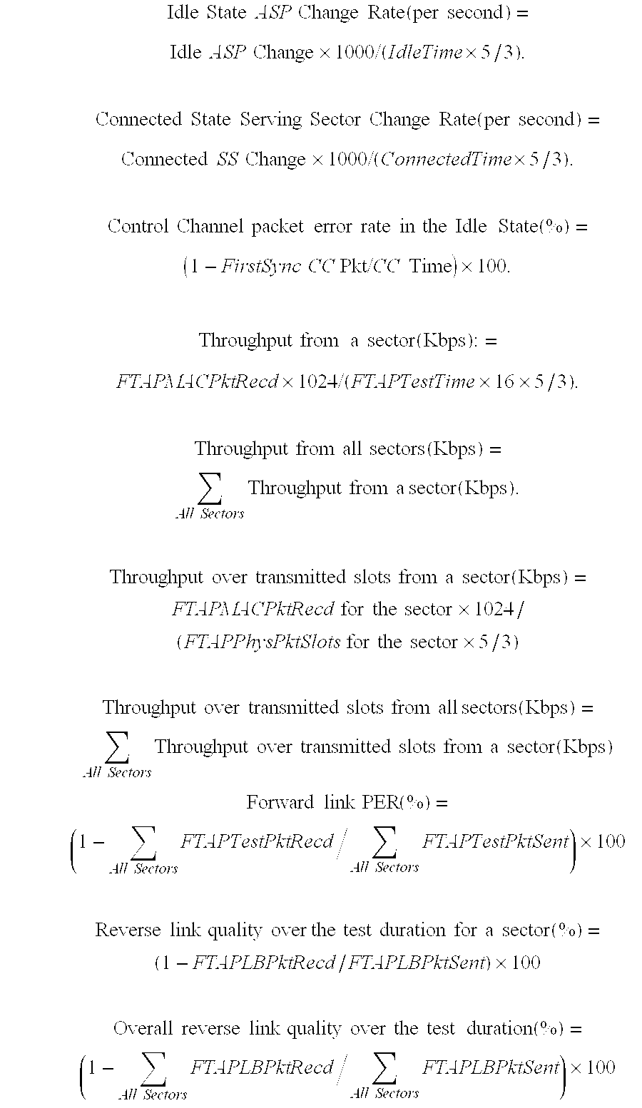
- The ratio of 5/3 in the above equations corresponds to the 1.667 msec for each time slot in cdma2000. Other performance metrics may also be derived based on other statistics that may be logged at the access network. For example, the DRC values received from the terminals may be logged to determine the DRC Symbol error performance on the DRC Channel.
- Referring back to FIG. 2B, at
terminal 106,RX data processor 260 may be operated to process the FTAP Test packets and to forward the packets viamultiplexer 262 tocontroller 270.Controller 270 then identifies and extracts various types of information from each received FTAP Test packet (e.g., the serving sector, the sequence number, and the length of each FTAP Test packet).Controller 270 then forms the FTAP Loop Back packets having the pertinent information as described above. The FTAP Loop Back packets may be stored inLoop Back buffer 278. At the appropriate time, the FTAP Loop Back packets are retrieved frombuffer 278, routed throughmultiplexer 284, and processed byTX data processor 286 for transmission over the Reverse Traffic Channel. - Referring back to FIG. 2A, at
access point 104, the FTAP Loop Back packets are processed byRX data processor 234 and provided tocontroller 220.Controller 220 then identifies and extracts various types of information from each received FTAP Loop Back packet (e.g., the serving sector, the sequence number, and the length of each covered FTAP Test packet).Controller 220 further updates the variables maintained for each serving sector based on the information extracted from the received FTAP Loop Back packets, as described above.Controller 220 may further be operated to perform the computations described above for the various forward link performance metrics. Other forward link performance metrics may be derived based on other statistics that may be logged at the access terminal. For example, by logging the received FTAP Test packets, Forward Traffic Channel Packet Miss probability, Packet Reception False Alarm probability, and so on, can be determined. - Reverse Test Application Protocol (RTAP)
- The RTAP provides the procedures and messages used to configure, control, and perform various tests of the reverse channels, including the Reverse Traffic Channel. The procedures for the RTAP may be grouped into the following categories:
- Test Parameter Configuration—includes procedures and messages to control RTAP test configurations at the terminal and access network; and
- RTAP Test Packet Transmission and Reception—includes procedures for generating RTAP Test packets and RTAP Fill packets at the terminal, transmitting the generated packets at configured rates on the Reverse Traffic Channel, and processing the received packets at the access network.
- The procedures and messages are described in further detail below. Fewer, additional, and/or different procedures and messages may also be provided for the RTAP, and this is within the scope of the invention.
- The RTAP supports the testing of the Reverse Traffic Channel at various rates. Table 14 lists various modes supported by the Reverse Traffic Channel.
TABLE 14 Mode Description RTAP Test enabled to test the Reverse Traffic Channel Packet Mode Configured Packet enabled to test the Reverse Traffic Channel at Rate Mode various rates - The RTAP supports the collection of certain statistics by the access network, which may be used to determine various performance metrics such as throughput and packet error rate. Table 15 lists the statistics that may be collected and maintained by the access network.
TABLE 15 Parameter Description RTAPTestPktSent[i] an array whose i-th element contains the number of RTAP Test packets that were sent by the terminal at a rate corresponding to RateIndex i shown in Table 18 RTAPTestPktRecd[i] an array whose i-th element contains the number of RTAP Test packets that were received by the access network at a rate corresponding to RateIndex i RTAPTestTime the duration of the RTAP test (in frames) - FIG. 7 is a diagram of an
overall process 700 for testing the Reverse Traffic Channel, in accordance with an embodiment of the invention.Process 700 may be used for various tests such as, for example, reverse link throughput, packet error rate, and so on. - Initially, the access network sets up a connection with the terminal in the normal manner, if there is no current connection between them, at
step 712. The access network then sends an RTAPParameterAssignment message to the terminal to configure RTAP, atstep 714. The message includes an RTAPTestPktEnable attribute record to enable transmission of RTAP Test packets by the access terminal. The terminal performs the necessary configuration and then responds to the access network with an RTPParameterComplete message to indicate that it is ready for the configured tests, atstep 716. - The terminal thereafter sends RTAP Test packets to the access network, at
step 718. Any number of packets may be sent, and the statistics to be collected by the access network and/or terminal may be determined by the test configuration. - After sufficient statistics have been collected, the access network releases the connection, at
step 720. Step 720 may be omitted, for example, if the access network proceeds to perform some other tests or functions. The access network may use the statistics it collected to compute the packet error rate and the throughput, as described below. Various details forprocess 700 are described below. - RTAP Test Parameter Configuration
- The access network or the terminal may activate the RTAP to test the reverse channels. Upon activation of the RTAP, the terminal performs an RTAP Configuration Initialization procedure, which disables the flags for the RTAP Test Packet mode and the Configured Packet Rate mode.
- FIG. 8 is a flow diagram of a specific embodiment of an RTAP Test
Parameter Configuration process 800.Process 800 coverssteps step 812. Via the attribute records in the message, the access network is able to control the tests to be performed. - Upon receiving the RTAPParameterAssignment message from the access network, the terminal performs the RTAP Configuration Initialization procedure described above, at
step 814. The terminal then performs an RTAP Test Parameter Initialization procedure, atstep 816. In an embodiment, this procedure sets to zero a (12-bit) variable, Vi(SRev), used to track the sequence number of the RTAP Test packets transmitted at the rate corresponding to RateIndex i (shown in Table 18), for all possible Reverse Traffic Channel rates (i.e., for all possible value of i). - The terminal also sets its RTAP mode flags based on the attributes, if any, included in the received message, at
step 818. In particular, the received message may include an RTAPTestPktEnable attribute and/or a PacketRateMode attribute. The RTAPTestPktEnable attribute is included if the terminal is to start sending RTAP Test packets on the Reverse Traffic Channel, and the PacketRateMode attribute is included if the Reverse Traffic Channel rate is to be configured. - If the received message includes the RTAPTestPktEnable attribute, then the RTAP Test Packet mode is enabled, the value of the RTAPTestPktPersistence field in the attribute is stored, the RTAP Test Packet buffer (e.g.,
buffer 280 in FIG. 2B) is cleared, and a TestPktOverflowBit is set to zero. And if the received message includes the PacketRateMode attribute, then the Configured Packet Rate mode is enabled and the values of the MinRate and MaxRate fields in the attribute are stored. - Upon completion of the RTAP test configurations specified by the RTAPParameterAssignment message and within T RTAPConfig (e.g., two) seconds of receiving the message, the terminal sends an RTAPParameterComplete message with the TransactionID field set to the same value as that received in the corresponding RTAPParameterAssignment message, at
step 820. - Upon receiving the RTAPParameterComplete message from the terminal, the access network performs an RTAP Test Statistics and Parameters Initialization procedure, which resets RTAPTestPktSent[i], RTAPTestPktRecd[i], and RTAPTestTime to zeros (for all possible values of i), at
step 822. - The terminal also resets its RTAP mode flags upon termination of the RTAP testing. In an embodiment, if the RTAP receives a ConnectedState.ConnectionClosed or a RouteUpdate.ConnectionLost indication from the upper signaling layer, then the Configured Packet Rate mode is disabled and the RTAP Test Packet mode is also disabled if it was previously enabled and if the value of the RTAPTestPktPersistence field of the RTAPTestPktEnable attribute in the last received RTAPParameterAssignment message was ‘00’.
- Table 16 lists the fields for the RTAPParameterAssignment message, in accordance with a specific embodiment.
TABLE 16 Length Field (bits) Description MessageID 8 set to 0x80 by the access network TransactionID 8 set to one higher (modulo 256) than the TransactionID field value of the last RTAPParameterAssignment message sent to the terminal Zero or more occurrences of the following record: AttributeRecord Attribute attribute record for RTAPTestPktEnable or Dependent PacketRateMode; a simple record defined in section 10.3 of the HAI Document - Table 17 lists the various fields for the attribute records that may be included in the RTAPParameterAssignment message, in accordance with a specific embodiment. The first column of Table 17 identifies the two different attribute records that may be included in the RTAPParameterAssignment message. The RTAPTestPktEnable attribute record includes three fields—Length, Attribute ID, and RTAPTestPktPersistence. The PacketRateMode attribute record includes four fields—Length, Attribute ID, MinRate, and MaxRate. The Length field gives the length of the attribute record (in octets) excluding the Length field itself, which is two octets. Thus, the length of the RTAPTestPktEnable attribute record is 6 octets or 24 bits, and the length of the RTAPTestPktEnable attribute record is 8 octets or 32 bits.
TABLE 17 Attribute Length Attribute Attribute Record (octets) ID Data Field(s) and Description RTAPTest- 0x02 0x00 RTAPTestPktPersistence - set to PktEnable 0x01 if the RTAP Test Packet Enable mode is to be maintained in the event of a connection closure or a lost connection, and to 0x00 otherwise PacketRate- 0x03 0x01 MinRate - set to the RateIndex Mode corresponding to the minimum rate that the terminal can use to transmit RTAP Test packets (default = 0x00); MaxRate - set to the RateIndex corresponding to the maximum rate that the terminal can use to transmit RTAP Test packets (default = 0×05) - Table 18 lists the mapping of the RateIndex values to the Reverse Traffic Channel rates.
TABLE 18 RateIndex Reverse Traffic Channel (RTC) Rate 0 0 Kbps 1 9.6 Kbps 2 19.2 Kbps 3 38.4 Kbps 4 76.8 Kbps 5 153.6 Kbps all other values invalid - In an embodiment, the RTAPParameterAssignment message is sent on the Control Channel and the Forward Traffic Channel addressed to the terminal with the SLP set to reliable and the transmission priority set to 40.
- Table 19 lists the fields for the RTAPParameterComplete message, in accordance with a specific embodiment.
TABLE 19 Length Field (bits) Description MessageID 8 set to 0x81 by the terminal TransactionID 8 set to the value of the TransactionID field in the corresponding RTAPParameterAssignment message - In an embodiment, the RTAPParameterComplete message is sent on the Reverse Traffic Channel addressed to the access network (unicast addressing) with the SLP set to reliable and the transmission priority set to 40.
- RTAP Packet Transmission and Reception
- If the RTAP Test Packet mode is enabled, then the terminal generates and sends RTAP Test packets on the Reverse Traffic Channel to the access network. In an embodiment, an RTAP Test packet is generated for each particular time interval (e.g., every 16-slot interval, aligned to the CDMA system time). In an embodiment, the RTAP Test packets include information that covers RTC Physical Layer packets transmitted up to, but not including, the time instant of generation.
- Table 20 lists the fields for an RTAP Test packet, in accordance with a specific embodiment.
TABLE 20 Length Field (bits) Description ProtocolID 2 the protocol to which this packet belongs - set to ‘01’ for RTAP packets PacketType 4 the packet type within the RTAP - set to 0x0 RevSysTime 8 the CDMA system time (in frames mod 256) corresponding to the slot boundary when the RTAP Test packet was generated RTAPTestPkt- 1 flag to indicate if any RTAP Test packets were lost due to Overflow buffer overflow at the terminal - set to the value of the RTAPTestPktOverflowBit Seq_0 12 the sequence number of the last RTAP Test packet transmitted at a rate of 0 Kbps prior to the generation of this RTAP Test packet Seq_1 12 the sequence number of the last RTAP Test packet transmitted at a rate of 9.6 Kbps prior to the generation of this RTAP Test packet Seq_2 12 the sequence number of the last RTAP Test packet transmitted at a rate of 19.2 Kbps prior to the generation of this RTAP Test packet Seq_3 12 the sequence number of the last RTAP Test packet transmitted at a rate of 38.4 Kbps prior to the generation of this RTAP Test packet Seq_4 12 the sequence number of the last RTAP Test packet transmitted at a rate of 76.8 Kbps prior to the generation of this RTAP Test packet Seq_5 12 the sequence number of the last RTAP Test packet transmitted at a rate of 153.6 Kbps prior to the generation of this RTAP Test packet Reserved 7 (may be set to zero by the terminal and ignored by the access network) - Since one RTAP Test packet is expected to be transmitted by the terminal for each frame, the RevSysTime included in each RTAP Test packet may be used as the sequence number for the packet.
- If the Configured Packet Rate mode is enabled, the terminal transmits a (variable length) RTAP Fill packet of the size necessary to fill up the Reverse Traffic Channel packet containing the RTAP Test packet at the selected rate. Table 21 lists the fields for an FTAP Fill packet, in accordance with a specific embodiment.
TABLE 21 Length Field (bits) Description ProtocolID 2 the protocol to which this packet belongs - set to ‘01’ for RTAP packets PacketType 4 the packet type within the RTAP - set to 0x1 DataFill variable (may be set to zero by the terminal and ignored by the access network) - The generated RTAP Test packets are queued for transmission on the Reverse Traffic Channel, and the terminal provides buffering (e.g., in
buffer 280 in FIG. 2B) for a particular number of (e.g., eight or more) RTAP Test packets. The RTAPTestPktOverflowBit indicates if any RTAP Test packets have been lost due to buffer overflow, and is set to ‘1’ if this occurs. - The RTAP Test packets are transmitted in accordance with a set of rules, an embodiment of which is described as follows. RTAP Test packets are assigned a particular transmission priority (e.g., 55), and the RTAP Fill packets (if any) are also assigned another particular transmission priority (e.g., 255). The terminal transmits the queued RTAP Test packets and RTAP Fill packets (if any) in the Connected State.
- In an embodiment, the RTAP Test packets are transmitted at rates determined based on a defined rate selection scheme. If the Configured Packet Rate mode is enabled, then the terminal selects a Reverse Traffic Channel rate in accordance with a set of rules, an embodiment of which is described below. Otherwise, the terminal selects a rate in accordance with a Reverse Traffic Channel MAC Protocol described in the aforementioned HAI Document.
TABLE 22 Parameter Description MinRate the value of the MinRate field in the PackerRateMode attribute of the received RTAPParameterAssignment message MaxRate the value of the MaxRate field in the PackerRateMode attribute of the received RTAPParameterAssignment message MACMaxRate the RateIndex corresponding to the maximum rate allowed by the Reverse Traffic Channel MAC protocol TargetRate the RateIndex corresponding to the desired rate SelectedRate the RateIndex corresponding to the selected rate - For the first RTAP Test packet, the terminal sets TargetRate to MinRate and further sets SelectedRate to the smaller of TargetRate and MACMaxRate. For each subsequent RTAP Test packet, the terminal selects the rate for the packet based on the following procedure:
- TargetRate=
TargetRate+ 1, - If (TargetRate>MaxRate) then TargetRate=MinRate, and
- SelectedRate=Min (TargetRate, MACMaxRate).
- The above procedure cycles through all supported rates, up to and limited by the MaxRate specified by the RTAPParameterAssignment message and the MACMaxRate allowed by the MAC protocol. If the terminal transmits a Reverse Traffic Channel packet containing an RTAP Test packet at a rate with RateIndex i, it increments the associated sequence number for the transmitted RTAP Test packet by incrementing the variable V i(SRev).
- If the terminal receives a ConnectedState.ConnectionClosed or a RouteUpdate.ConnectionLost indication, it does not attempt to establish a connection for transmission of any RTAP Test packets that may have remained in the queue.
- In an embodiment, the access network maintains several variables, V(R RTAP) and X[i], to keep track of the RTAP Test packets. V(RRTAP) is an 8-bit variable that corresponds to the sequence number of the next RTAP Test packet expected to be received by the access network, and X[i] is an array of 12-bit variables, each of which corresponds to the sequence number of the next RTAP Test Packet expected to be contained in a Reverse Traffic Channel Physical Layer packet transmitted at a rate corresponding to RateIndex i. These variables are initialized by the access network upon receiving the first RTAP Test packet following receipt of an RTAPParameterComplete message. For the initialization, V(RRTAP) is set to the RevSysTime field of the RTAP Test packet, and X[i] is set to the Seq_i field of the first RTAP Test packet (for all possible values of i).
- In an embodiment, for each RTAP Test packet received at a rate corresponding to RateIndex k, the access network processes the received packet based on the following procedure and using the value of the RevSysTime field in the received packet:
- If RevSysTime≧V(R RTAP), then
- RTAPTestPktRecd[k] is incremented by 1,
- RTAPTestTime is incremented by {RevSysTime−V(RRTAP)+1}, and
- V(R RTAP) is set to
RevSysTime+ 1. - If RevSysTime <V(R RTAP), then generate an RTAPSyncLost indication.
- In an embodiment, the access network further processes the fields of the received RTAP Test packet using the values of the Seq_k fields (for all possible values of k) as follows:
- RTAPTestPktSent[k] is incremented by {Seq_k−X[k]+1}, and X[k] is set to
Seq_k+ 1. - In an embodiment, operations and comparisons performed on sequence numbers are carried out in unsigned modulo 2 S arithmetic, where S denotes the number of bits used to represent the sequence number.
- The reverse link performance may be determined based on the collected statistics. Some of the performance computations are described below. In the following, PhysLayerPktSize[i] gives the number of bits in a Physical Layer packet at a rate corresponding to RateIndex i.

- Referring back to FIG. 2B, at
terminal 106,controller 270 may be operated to generate the RTAP Test packets, which may be stored inbuffer 280. At the appropriate time, the RTAP Test packets are retrieved frombuffer 280, routed throughmultiplexer 284, and processed byTX data processor 286 for transmission over the Reverse Traffic Channel.Controller 270 may further provide a rate control tomodulator 288 for the selected rates for the RTAP Test packets. - Referring back to FIG. 2A, at
access point 104, the RTAP Test packets are processed byRX data processor 234 and provided tocontroller 220.Controller 220 then identifies and extracts various types of information from each RTAP Test packet (e.g., the rate and the sequence number of each received RTAP Test packet and the sequence numbers of the last transmitted packets for all possible rates).Controller 220 further updates the variables maintained for the rates based on the information extracted from the received RTAP Test packets, as described above.Controller 220 may further be operated to perform the computations described above for various reverse link performance metrics. - The above description represents one specific implementation of the inventive techniques. Fewer, additional, and/or different tests may be performed, and fewer, additional, and/or different statistics may be collected. Moreover, fewer, additional, and/or different procedures and messages may be provided, and each message may include fewer, additional, and/or different fields than those described above. Thus, various variations of the specific implementation described above may be contemplated and are within the scope of the invention.
- For clarity, various aspects and embodiments of the invention have been specifically described for the high rate packet data in cdma2000. The techniques described herein may also be used for other CDMA and wireless communication systems. For example, these techniques may be used in W-CDMA systems. Various differences exist between cdma2000 HAI and W-CDMA, and the techniques described herein may be modified for use in W-CDMA (e.g., modified to account for the difference in signal processing).
- The techniques described herein may be implemented by various means. For example, the techniques may be implemented in hardware, software, or a combination thereof. For a hardware implementation, the elements used for testing and statistics collection may be implemented within one or more application specific integrated circuits (ASICs), digital signal processors (DSPs), digital signal processing devices (DSPDs), programmable logic devices (PLDs), field programmable gate arrays (FPGAs), processors, controllers, micro-controllers, microprocessors, other electronic units designed to perform the functions described herein, or a combination thereof.
- For a software implementation, the elements used for testing and statistics collection may be implemented with modules (e.g., procedures, functions, and so on) that perform the functions described herein. The software codes may be stored in a memory unit (e.g.,
memories controllers - Headings are included herein for reference and to aid in the locating certain sections. These heading are not intended to limit the scope of the concepts described therein under, and these concepts may have applicability in other sections throughout the entire specification.
- The previous description of the disclosed embodiments is provided to enable any person skilled in the art to make or use the present invention. Various modifications to these embodiments will be readily apparent to those skilled in the art, and the generic principles defined herein may be applied to other embodiments without departing from the spirit or scope of the invention. Thus, the present invention is not intended to be limited to the embodiments shown herein but is to be accorded the widest scope consistent with the principles and novel features disclosed herein.
Claims (68)
Priority Applications (24)
| Application Number | Priority Date | Filing Date | Title |
|---|---|---|---|
| US10/015,926 US8089888B2 (en) | 2001-12-10 | 2001-12-10 | Method and apparatus for testing traffic and auxiliary channels in a wireless data communication system |
| UA20040705609A UA82317C2 (en) | 2001-12-10 | 2002-05-12 | Techniques and a device to test perfomance of traffic channels as well as auxiliary channels in wireless system (variants) |
| BR0214831-5A BR0214831A (en) | 2001-12-10 | 2002-12-05 | Method and equipment for testing traffic channels and auxiliary channels in a wireless data communication system |
| RU2004121141/09A RU2310999C2 (en) | 2001-12-10 | 2002-12-05 | Method and device for testing traffic and auxiliary channels in a wireless data transmission system |
| BRPI0214831-5A BRPI0214831B1 (en) | 2001-12-10 | 2002-12-05 | METHOD AND EQUIPMENT FOR TESTING TRAFFIC AND AUXILIARY CHANNELS IN A WIRELESS DATA COMMUNICATION SYSTEM |
| AT02786951T ATE468721T1 (en) | 2001-12-10 | 2002-12-05 | METHOD AND DEVICE FOR TESTING TRAFFIC AND AUXILIARY CHANNELS IN A WIRELESS DATA COMMUNICATIONS SYSTEM |
| JP2003552016A JP4890739B2 (en) | 2001-12-10 | 2002-12-05 | Method and apparatus for testing traffic and auxiliary channels in a wireless data communication system |
| CN02827959XA CN1618243B (en) | 2001-12-10 | 2002-12-05 | Method and apparatus for testing traffic and auxiliary channels in a wireless data communication system |
| IL16237402A IL162374A0 (en) | 2001-12-10 | 2002-12-05 | Method and system for testing traffic and auxiliary channels in a wireless data communication system |
| ES02786951T ES2343569T3 (en) | 2001-12-10 | 2002-12-05 | PROCEDURE AND APPLIANCE TO SUBMIT TRIAL CHANNELS AND AUXILIARY CHANNELS IN A WIRELESS DATA COMMUNICATION SYSTEM. |
| MXPA04005588A MXPA04005588A (en) | 2001-12-10 | 2002-12-05 | Method and apparatus for testing traffic and auxiliary channels in a wireless data communication system. |
| PCT/US2002/039210 WO2003051076A1 (en) | 2001-12-10 | 2002-12-05 | Method and apparatus for testing traffic and auxiliary channels in a wireless data communication system |
| DE60236451T DE60236451D1 (en) | 2001-12-10 | 2002-12-05 | METHOD AND DEVICE FOR CHECKING TRANSPORT AND ASSISTANCE CHANNELS IN A WIRELESS DATA COMMUNICATION SYSTEM |
| AU2002351303A AU2002351303B2 (en) | 2001-12-10 | 2002-12-05 | Method and apparatus for testing traffic and auxiliary channels in a wireless data communication system |
| KR1020047008936A KR100970354B1 (en) | 2001-12-10 | 2002-12-05 | Method and apparatus for testing traffic and auxiliary channels in a wireless data communication system |
| EP02786951A EP1452048B1 (en) | 2001-12-10 | 2002-12-05 | Method and apparatus for testing traffic and auxiliary channels in a wireless data communication system |
| EP10003714.2A EP2211572B1 (en) | 2001-12-10 | 2002-12-05 | Methods and apparatuses for testing traffic and auxiliary channels in a wireless data communication system on the basis of test packets formed and transmitted according to test settings previously received |
| CA2469707A CA2469707C (en) | 2001-12-10 | 2002-12-05 | Method and apparatus for testing traffic and auxiliary channels in a wireless data communication system |
| TW091135672A TWI263419B (en) | 2001-12-10 | 2002-12-10 | Method and apparatus for testing traffic and auxiliary channels in a wireless data communication system |
| IL162374A IL162374A (en) | 2001-12-10 | 2004-06-06 | Method and system for testing traffic and auxiliary channels in a wireless data communication system |
| NO20042911A NO329036B1 (en) | 2001-12-10 | 2004-07-09 | Testing of traffic and auxiliary channels in a wireless data communication system |
| JP2009147140A JP2010016811A (en) | 2001-12-10 | 2009-06-22 | Method and apparatus for testing traffic and auxiliary channel in wireless data communication system |
| JP2011194900A JP2012039630A (en) | 2001-12-10 | 2011-09-07 | Method and apparatus for testing traffic and auxiliary channels in wireless data communication system |
| US13/228,832 US8780735B2 (en) | 2001-12-10 | 2011-09-09 | Method and apparatus for testing traffic and auxiliary channels in a wireless data communication system |
Applications Claiming Priority (1)
| Application Number | Priority Date | Filing Date | Title |
|---|---|---|---|
| US10/015,926 US8089888B2 (en) | 2001-12-10 | 2001-12-10 | Method and apparatus for testing traffic and auxiliary channels in a wireless data communication system |
Related Child Applications (1)
| Application Number | Title | Priority Date | Filing Date |
|---|---|---|---|
| US13/228,832 Continuation US8780735B2 (en) | 2001-12-10 | 2011-09-09 | Method and apparatus for testing traffic and auxiliary channels in a wireless data communication system |
Publications (2)
| Publication Number | Publication Date |
|---|---|
| US20030142629A1 true US20030142629A1 (en) | 2003-07-31 |
| US8089888B2 US8089888B2 (en) | 2012-01-03 |
Family
ID=21774379
Family Applications (2)
| Application Number | Title | Priority Date | Filing Date |
|---|---|---|---|
| US10/015,926 Active 2025-03-29 US8089888B2 (en) | 2001-12-10 | 2001-12-10 | Method and apparatus for testing traffic and auxiliary channels in a wireless data communication system |
| US13/228,832 Expired - Fee Related US8780735B2 (en) | 2001-12-10 | 2011-09-09 | Method and apparatus for testing traffic and auxiliary channels in a wireless data communication system |
Family Applications After (1)
| Application Number | Title | Priority Date | Filing Date |
|---|---|---|---|
| US13/228,832 Expired - Fee Related US8780735B2 (en) | 2001-12-10 | 2011-09-09 | Method and apparatus for testing traffic and auxiliary channels in a wireless data communication system |
Country Status (18)
| Country | Link |
|---|---|
| US (2) | US8089888B2 (en) |
| EP (2) | EP2211572B1 (en) |
| JP (3) | JP4890739B2 (en) |
| KR (1) | KR100970354B1 (en) |
| CN (1) | CN1618243B (en) |
| AT (1) | ATE468721T1 (en) |
| AU (1) | AU2002351303B2 (en) |
| BR (2) | BRPI0214831B1 (en) |
| CA (1) | CA2469707C (en) |
| DE (1) | DE60236451D1 (en) |
| ES (1) | ES2343569T3 (en) |
| IL (2) | IL162374A0 (en) |
| MX (1) | MXPA04005588A (en) |
| NO (1) | NO329036B1 (en) |
| RU (1) | RU2310999C2 (en) |
| TW (1) | TWI263419B (en) |
| UA (1) | UA82317C2 (en) |
| WO (1) | WO2003051076A1 (en) |
Cited By (43)
| Publication number | Priority date | Publication date | Assignee | Title |
|---|---|---|---|---|
| US20030179728A1 (en) * | 2002-03-25 | 2003-09-25 | Agere Systems Inc. | Method for improved data communication due to improved data processing within a transceiver |
| US20040068681A1 (en) * | 2002-10-08 | 2004-04-08 | Geoff Smith | Building packets of data |
| US20040202476A1 (en) * | 2003-04-09 | 2004-10-14 | Woolf Kevin Reid | Tables for determining the signal strength of a received signal in a fibre optics transceiver |
| US20050138155A1 (en) * | 2003-12-19 | 2005-06-23 | Michael Lewis | Signal assessment |
| US20050259594A1 (en) * | 2004-05-21 | 2005-11-24 | Geoff Smith | Distributed data model |
| US20050286440A1 (en) * | 2004-06-24 | 2005-12-29 | Meshnetworks, Inc. | System and method for adaptive rate selection for wireless networks |
| US20060002306A1 (en) * | 2004-06-30 | 2006-01-05 | Ronald Brown | Failure detection of path information corresponding to a transmission path |
| US20060198359A1 (en) * | 2005-03-04 | 2006-09-07 | Kenny Fok | Apparatus and methods for determining voice and/or data processing performance of a wireless device |
| US20070105544A1 (en) * | 2004-01-30 | 2007-05-10 | Andras Veres | Method for determining mobile terminal performance in a running wireless network |
| US20070130352A1 (en) * | 2005-10-28 | 2007-06-07 | Microsoft Corporation | Task offload to a peripheral device |
| US20070189175A1 (en) * | 2006-02-14 | 2007-08-16 | Finisar Corporation | Capture timing and negotiation data with repeat counts in a networking diagnostic component |
| US20070189176A1 (en) * | 2006-02-14 | 2007-08-16 | Finisar Corporation | Random data compression scheme in a network diagnostic component |
| US20070206509A1 (en) * | 2006-03-03 | 2007-09-06 | Finisar Corporation | Capture rcdt and sntt sas speed negotiation decodes in a network diagnostic component |
| US20080031129A1 (en) * | 2006-08-07 | 2008-02-07 | Jim Arseneault | Smart Ethernet edge networking system |
| US20080045185A1 (en) * | 2006-08-18 | 2008-02-21 | Samsung Electronics Co., Ltd. | Method and apparatus for reporting reception ratio of streaming service by terminal in a mobile broadcasting system, and system thereof |
| EP1902544A2 (en) * | 2005-07-12 | 2008-03-26 | Nokia Corporation | Optimized rfid/nfc ber testing |
| US20080189641A1 (en) * | 2006-02-14 | 2008-08-07 | Finisar Corporation | Show oob and speed negotiation data graphically in a network diagnostic component |
| US20090268713A1 (en) * | 2008-04-23 | 2009-10-29 | Vonage Holdings Corporation | Method and apparatus for testing in a communication network |
| US20110103235A1 (en) * | 2009-10-30 | 2011-05-05 | Anh Luong | Wireless local area network test system with forced transmit rates during protocol-based testing |
| US7948902B1 (en) * | 2004-03-03 | 2011-05-24 | Globalfoundries Inc. | Method of generating packets without repetition in verification of a device |
| US20110182268A1 (en) * | 2010-01-22 | 2011-07-28 | Haseeb Akhtar | Optimization of non-optimized handoff from a first access technology to a second access technology |
| US8089888B2 (en) * | 2001-12-10 | 2012-01-03 | Qualcomm Incorporated | Method and apparatus for testing traffic and auxiliary channels in a wireless data communication system |
| US20120100812A1 (en) * | 2009-06-25 | 2012-04-26 | Bandrich Inc. | Mobile communication method and device thereof |
| US20130016618A1 (en) * | 2011-07-15 | 2013-01-17 | Motorola Solutions, Inc. | Self-testing of services in an access point of a communication network |
| US20130329563A1 (en) * | 2008-03-18 | 2013-12-12 | Qualcomm Incorporated | Method of network management by assistance from terminal using control-plane signaling between terminal and network |
| US8769152B2 (en) | 2006-02-14 | 2014-07-01 | Jds Uniphase Corporation | Align/notify compression scheme in a network diagnostic component |
| US20150124631A1 (en) * | 2013-11-05 | 2015-05-07 | Insieme Networks Inc. | Networking apparatuses and packet statistic determination methods employing atomic counters |
| US9154981B2 (en) | 2011-02-18 | 2015-10-06 | Kyushu University, National University Corporation | Transmission period determination method, transmission period determination device and program |
| US20170295099A1 (en) * | 2016-04-11 | 2017-10-12 | Arista Networks, Inc. | System and method of load balancing across a multi-link group |
| US10079761B2 (en) | 2013-11-05 | 2018-09-18 | Cisco Technology, Inc. | Hierarchical routing with table management across hardware modules |
| US10148586B2 (en) | 2013-11-05 | 2018-12-04 | Cisco Technology, Inc. | Work conserving scheduler based on ranking |
| US10164782B2 (en) | 2013-11-05 | 2018-12-25 | Cisco Technology, Inc. | Method and system for constructing a loop free multicast tree in a data-center fabric |
| US10182496B2 (en) | 2013-11-05 | 2019-01-15 | Cisco Technology, Inc. | Spanning tree protocol optimization |
| US10187302B2 (en) | 2013-11-05 | 2019-01-22 | Cisco Technology, Inc. | Source address translation in overlay networks |
| US10374878B2 (en) | 2013-11-05 | 2019-08-06 | Cisco Technology, Inc. | Forwarding tables for virtual networking devices |
| US10382345B2 (en) | 2013-11-05 | 2019-08-13 | Cisco Technology, Inc. | Dynamic flowlet prioritization |
| US10516612B2 (en) | 2013-11-05 | 2019-12-24 | Cisco Technology, Inc. | System and method for identification of large-data flows |
| US10547544B2 (en) | 2013-11-05 | 2020-01-28 | Cisco Technology, Inc. | Network fabric overlay |
| US10778584B2 (en) | 2013-11-05 | 2020-09-15 | Cisco Technology, Inc. | System and method for multi-path load balancing in network fabrics |
| CN111858703A (en) * | 2020-06-29 | 2020-10-30 | 浪潮电子信息产业股份有限公司 | Method and device for counting performance test data of benchmark SQL |
| US10951522B2 (en) | 2013-11-05 | 2021-03-16 | Cisco Technology, Inc. | IP-based forwarding of bridged and routed IP packets and unicast ARP |
| US20220151022A1 (en) * | 2020-11-12 | 2022-05-12 | Nvidia Corporation | Intra-layer adapter for fifth generation new radio (5g-nr) communications |
| US11888646B2 (en) | 2020-10-05 | 2024-01-30 | Lg Energy Solution, Ltd. | Battery management apparatus and method |
Families Citing this family (69)
| Publication number | Priority date | Publication date | Assignee | Title |
|---|---|---|---|---|
| US9226308B2 (en) | 2003-10-15 | 2015-12-29 | Qualcomm Incorporated | Method, apparatus, and system for medium access control |
| US8233462B2 (en) | 2003-10-15 | 2012-07-31 | Qualcomm Incorporated | High speed media access control and direct link protocol |
| US8284752B2 (en) | 2003-10-15 | 2012-10-09 | Qualcomm Incorporated | Method, apparatus, and system for medium access control |
| US8472473B2 (en) | 2003-10-15 | 2013-06-25 | Qualcomm Incorporated | Wireless LAN protocol stack |
| US8483105B2 (en) | 2003-10-15 | 2013-07-09 | Qualcomm Incorporated | High speed media access control |
| US8462817B2 (en) | 2003-10-15 | 2013-06-11 | Qualcomm Incorporated | Method, apparatus, and system for multiplexing protocol data units |
| US8842657B2 (en) | 2003-10-15 | 2014-09-23 | Qualcomm Incorporated | High speed media access control with legacy system interoperability |
| US8903440B2 (en) * | 2004-01-29 | 2014-12-02 | Qualcomm Incorporated | Distributed hierarchical scheduling in an ad hoc network |
| JP4115403B2 (en) * | 2004-02-18 | 2008-07-09 | キヤノン株式会社 | Luminescent substrate and image display device |
| US8315271B2 (en) | 2004-03-26 | 2012-11-20 | Qualcomm Incorporated | Method and apparatus for an ad-hoc wireless communications system |
| US7616665B2 (en) | 2004-04-13 | 2009-11-10 | Research In Motion Limited | Method and system for monitoring the health of wireless telecommunication networks |
| US7564814B2 (en) | 2004-05-07 | 2009-07-21 | Qualcomm, Incorporated | Transmission mode and rate selection for a wireless communication system |
| US8401018B2 (en) | 2004-06-02 | 2013-03-19 | Qualcomm Incorporated | Method and apparatus for scheduling in a wireless network |
| US8363604B2 (en) | 2005-02-01 | 2013-01-29 | Qualcomm Incorporated | Method and apparatus for controlling a transmission data rate based on feedback relating to channel conditions |
| CN100384281C (en) * | 2005-03-21 | 2008-04-23 | 华为技术有限公司 | Method for carrying out connected state test |
| US7873321B2 (en) | 2005-03-29 | 2011-01-18 | Qualcomm Incorporated | Apparatus and methods for determining network access performance of a wireless device |
| US9055552B2 (en) | 2005-06-16 | 2015-06-09 | Qualcomm Incorporated | Quick paging channel with reduced probability of missed page |
| PL1922841T3 (en) * | 2005-08-16 | 2010-10-29 | Qualcomm Inc | Methods and systems for adaptive server selection in wireless communications |
| US8600336B2 (en) * | 2005-09-12 | 2013-12-03 | Qualcomm Incorporated | Scheduling with reverse direction grant in wireless communication systems |
| EP1927258B1 (en) | 2005-09-21 | 2013-04-24 | LG Electronics Inc. | Method and appratus for multiplexing multiple reverse feedback channels in multicarrier wireless networks |
| WO2007050936A1 (en) | 2005-10-27 | 2007-05-03 | Qualcomm Incorporated | A method and apparatus for processing time overlapping non sticky (ns) unicast and sticky assignments |
| CN1992752A (en) * | 2005-12-30 | 2007-07-04 | 华为技术有限公司 | System, method and network equipment for implementing network equipment on-condition maintenance |
| CN100420325C (en) * | 2006-01-20 | 2008-09-17 | 信息产业部电信传输研究所 | Charge loading method for cdma2000 1xEV-DO system covering test |
| CN100454851C (en) * | 2006-03-17 | 2009-01-21 | 华为技术有限公司 | Measuring method and device and system for Diameter protocol interface |
| US9094257B2 (en) | 2006-06-30 | 2015-07-28 | Centurylink Intellectual Property Llc | System and method for selecting a content delivery network |
| US8717911B2 (en) * | 2006-06-30 | 2014-05-06 | Centurylink Intellectual Property Llc | System and method for collecting network performance information |
| US8488447B2 (en) | 2006-06-30 | 2013-07-16 | Centurylink Intellectual Property Llc | System and method for adjusting code speed in a transmission path during call set-up due to reduced transmission performance |
| US20080002711A1 (en) * | 2006-06-30 | 2008-01-03 | Bugenhagen Michael K | System and method for access state based service options |
| US8477614B2 (en) | 2006-06-30 | 2013-07-02 | Centurylink Intellectual Property Llc | System and method for routing calls if potential call paths are impaired or congested |
| US8289965B2 (en) | 2006-10-19 | 2012-10-16 | Embarq Holdings Company, Llc | System and method for establishing a communications session with an end-user based on the state of a network connection |
| US8531954B2 (en) * | 2006-08-22 | 2013-09-10 | Centurylink Intellectual Property Llc | System and method for handling reservation requests with a connection admission control engine |
| US7843831B2 (en) * | 2006-08-22 | 2010-11-30 | Embarq Holdings Company Llc | System and method for routing data on a packet network |
| US8224255B2 (en) * | 2006-08-22 | 2012-07-17 | Embarq Holdings Company, Llc | System and method for managing radio frequency windows |
| US7684332B2 (en) | 2006-08-22 | 2010-03-23 | Embarq Holdings Company, Llc | System and method for adjusting the window size of a TCP packet through network elements |
| US8223655B2 (en) | 2006-08-22 | 2012-07-17 | Embarq Holdings Company, Llc | System and method for provisioning resources of a packet network based on collected network performance information |
| US8015294B2 (en) | 2006-08-22 | 2011-09-06 | Embarq Holdings Company, LP | Pin-hole firewall for communicating data packets on a packet network |
| US9479341B2 (en) * | 2006-08-22 | 2016-10-25 | Centurylink Intellectual Property Llc | System and method for initiating diagnostics on a packet network node |
| US8549405B2 (en) | 2006-08-22 | 2013-10-01 | Centurylink Intellectual Property Llc | System and method for displaying a graphical representation of a network to identify nodes and node segments on the network that are not operating normally |
| US8064391B2 (en) | 2006-08-22 | 2011-11-22 | Embarq Holdings Company, Llc | System and method for monitoring and optimizing network performance to a wireless device |
| US8750158B2 (en) | 2006-08-22 | 2014-06-10 | Centurylink Intellectual Property Llc | System and method for differentiated billing |
| US8619600B2 (en) | 2006-08-22 | 2013-12-31 | Centurylink Intellectual Property Llc | System and method for establishing calls over a call path having best path metrics |
| US8199653B2 (en) | 2006-08-22 | 2012-06-12 | Embarq Holdings Company, Llc | System and method for communicating network performance information over a packet network |
| US8576722B2 (en) | 2006-08-22 | 2013-11-05 | Centurylink Intellectual Property Llc | System and method for modifying connectivity fault management packets |
| US8307065B2 (en) | 2006-08-22 | 2012-11-06 | Centurylink Intellectual Property Llc | System and method for remotely controlling network operators |
| US8228791B2 (en) | 2006-08-22 | 2012-07-24 | Embarq Holdings Company, Llc | System and method for routing communications between packet networks based on intercarrier agreements |
| US8537695B2 (en) | 2006-08-22 | 2013-09-17 | Centurylink Intellectual Property Llc | System and method for establishing a call being received by a trunk on a packet network |
| US8274905B2 (en) * | 2006-08-22 | 2012-09-25 | Embarq Holdings Company, Llc | System and method for displaying a graph representative of network performance over a time period |
| US8407765B2 (en) | 2006-08-22 | 2013-03-26 | Centurylink Intellectual Property Llc | System and method for restricting access to network performance information tables |
| US8144587B2 (en) | 2006-08-22 | 2012-03-27 | Embarq Holdings Company, Llc | System and method for load balancing network resources using a connection admission control engine |
| US8238253B2 (en) | 2006-08-22 | 2012-08-07 | Embarq Holdings Company, Llc | System and method for monitoring interlayer devices and optimizing network performance |
| US8189468B2 (en) | 2006-10-25 | 2012-05-29 | Embarq Holdings, Company, LLC | System and method for regulating messages between networks |
| US8130793B2 (en) | 2006-08-22 | 2012-03-06 | Embarq Holdings Company, Llc | System and method for enabling reciprocal billing for different types of communications over a packet network |
| US8743703B2 (en) | 2006-08-22 | 2014-06-03 | Centurylink Intellectual Property Llc | System and method for tracking application resource usage |
| US8144589B2 (en) | 2007-05-07 | 2012-03-27 | Qualcomm Incorporated | Learning-based semi-persistent scheduling in wireless communications |
| KR101401965B1 (en) * | 2007-05-25 | 2014-06-02 | 삼성전자주식회사 | Method for measuring a state of a plurality of channels and apparatus, Method for selecting idle channel and apparatus therefor |
| US8706123B2 (en) * | 2008-03-24 | 2014-04-22 | Qualcomm Incorporated | Common data channel resource usage report |
| RU2462834C2 (en) * | 2008-03-24 | 2012-09-27 | Квэлкомм Инкорпорейтед | Report on using resources of general data transfer channel |
| US8068425B2 (en) | 2008-04-09 | 2011-11-29 | Embarq Holdings Company, Llc | System and method for using network performance information to determine improved measures of path states |
| US8488553B2 (en) * | 2008-06-05 | 2013-07-16 | Alcatel Lucent | Method for providing seamless transition between networks following different protocols |
| JP4597242B2 (en) * | 2009-01-08 | 2010-12-15 | 株式会社エヌ・ティ・ティ・ドコモ | Test method and test apparatus |
| US9155103B2 (en) * | 2009-06-01 | 2015-10-06 | Qualcomm Incorporated | Coexistence manager for controlling operation of multiple radios |
| US9185719B2 (en) * | 2009-08-18 | 2015-11-10 | Qualcomm Incorporated | Method and apparatus for mapping applications to radios in a wireless communication device |
| US8842625B2 (en) * | 2009-10-14 | 2014-09-23 | Telefonaktiebolaget L M Ericsson (Publ) | Wireless scheduling considering overhead cost estimate |
| US8903314B2 (en) * | 2009-10-29 | 2014-12-02 | Qualcomm Incorporated | Bluetooth introduction sequence that replaces frequencies unusable due to other wireless technology co-resident on a bluetooth-capable device |
| US9197559B1 (en) * | 2011-04-29 | 2015-11-24 | Arris Enterprises, Inc. | Adaptive streaming using non-local information |
| US8693351B2 (en) * | 2011-07-26 | 2014-04-08 | Litepoint Corporation | System and method for deterministic testing of packet error rate in electronic devices |
| CN105453651B (en) * | 2013-12-19 | 2020-03-31 | 华为技术有限公司 | Access point selection method, terminal and access point |
| CN108293012B (en) * | 2015-11-26 | 2021-02-09 | 三菱电机株式会社 | Relay device and communication network |
| CN108075910B (en) | 2016-11-11 | 2021-07-16 | 华为技术有限公司 | Configuration method of communication equipment and communication equipment |
Citations (67)
| Publication number | Priority date | Publication date | Assignee | Title |
|---|---|---|---|---|
| US3860769A (en) * | 1972-11-01 | 1975-01-14 | Gte Lenkurt Inc | Method and apparatus for testing the operation of a communication system |
| US3922508A (en) * | 1974-01-14 | 1975-11-25 | Magnetic Controls Co | Coded telephone line testing equipment |
| US4156183A (en) * | 1976-07-10 | 1979-05-22 | Wandel & Goltermann | Method of and means for measuring the level of test signals over selected wide band frequency ranges |
| US4685102A (en) * | 1983-06-16 | 1987-08-04 | Mitel Corporation | Switching system loopback test circuit |
| US5271000A (en) * | 1991-03-22 | 1993-12-14 | International Business Machines Corporation | Method and apparatus for testing and evaluation of distributed networks |
| US5357557A (en) * | 1991-11-06 | 1994-10-18 | Nec Corporation | Inter-mobile-terminal testing method in cellular automobile telephone system |
| US5475732A (en) * | 1993-02-16 | 1995-12-12 | C & P Of Virginia | Common channeling signaling network maintenance and testing |
| US5521904A (en) * | 1993-12-07 | 1996-05-28 | Telefonaktiebolaget Lm Ericsson | Method and apparatus for testing a base station in a time division multiple access radio communications system |
| US5555266A (en) * | 1993-10-04 | 1996-09-10 | Motorola, Inc. | Method for reducing transmission delays in a packet transmission system |
| US5570357A (en) * | 1991-06-28 | 1996-10-29 | Alcatel N.V. | Testing the characteristics of an ATM connection between two points of an ATM network using ATM test cells |
| US5636212A (en) * | 1993-01-06 | 1997-06-03 | Nec Corporation | Burst bandwidth reservation method in asynchronous transfer mode (ATM) network |
| US5742589A (en) * | 1994-07-01 | 1998-04-21 | Mitsubishi Denki Kabushiki Kaisha | Radio apparatus |
| US5768689A (en) * | 1995-04-03 | 1998-06-16 | Telefonaktiebolaget Lm Ericsson | Transceiver tester |
| US5784406A (en) * | 1995-06-29 | 1998-07-21 | Qualcom Incorporated | Method and apparatus for objectively characterizing communications link quality |
| US5802105A (en) * | 1994-11-30 | 1998-09-01 | Qualcomm Incorporated | Method and apparatus for testing a digital communication channel |
| US5898674A (en) * | 1995-11-14 | 1999-04-27 | Paradyne Corporation | System and method for performing non-disruptive diagnostics through a frame relay circuit |
| US6006016A (en) * | 1994-11-10 | 1999-12-21 | Bay Networks, Inc. | Network fault correlation |
| US6014377A (en) * | 1998-08-05 | 2000-01-11 | Us West, Inc. | System and method for an integrated wireline/wireless service using private branch exchange lines |
| US6028845A (en) * | 1996-02-21 | 2000-02-22 | Fujitsu Limited | Communication-line-quality measuring system using a conventional signal frame structure |
| US6031845A (en) * | 1997-05-14 | 2000-02-29 | Airspan Communications Corporation | Allocation of bandwidth to calls in a wireless telecommunications system |
| US6069876A (en) * | 1997-02-13 | 2000-05-30 | Nortel Networks Corporation | Performance monitoring of an ATM Network |
| US6088588A (en) * | 1997-03-25 | 2000-07-11 | Nortel Networks Corporation | Method and wireless terminal for monitoring communications and providing network with terminal operation information |
| US6128284A (en) * | 1997-07-11 | 2000-10-03 | Fujitsu Limited | SDH-communication-network/already existing communication network monitoring and integrating apparatus and its method |
| US6169883B1 (en) * | 1996-03-07 | 2001-01-02 | Nokia Telecommunications Oy | Remote test of a subscriber connection in a system implementing a wireless subscriber connection |
| US6185191B1 (en) * | 1997-12-03 | 2001-02-06 | Harris Corporation | Testing of ISDN line via auxiliary channel signaling |
| US6246471B1 (en) * | 1998-06-08 | 2001-06-12 | Lj Laboratories, Llc | Apparatus and method for measuring optical characteristics of an object |
| US6246479B1 (en) * | 1998-06-08 | 2001-06-12 | Lj Laboratories, L.L.C. | Integrated spectrometer assembly and methods |
| US6249348B1 (en) * | 1998-11-23 | 2001-06-19 | Lj Laboratories, L.L.C. | Integrated spectrometer assembly and methods |
| US6253060B1 (en) * | 1996-12-20 | 2001-06-26 | Airnet Communications Corporation | Method and apparatus employing wireless remote loopback capability for a wireless system repeater to provide end-to-end testing without a wireline connection |
| US6259911B1 (en) * | 1998-01-06 | 2001-07-10 | Wireless Access | Network operations center hardware and software design |
| US6263016B1 (en) * | 1998-02-04 | 2001-07-17 | 3Com Corporation | Methods for interfacing a subscriber link to digital networks |
| US6272112B1 (en) * | 1997-11-13 | 2001-08-07 | Fujitsu Limited | Repeating unit testing system and communication apparatus as well as communication method |
| US20010023186A1 (en) * | 1998-02-13 | 2001-09-20 | Rajeev Krishnamurthi | System and method for base station initiated call setup |
| US20010038453A1 (en) * | 1999-12-23 | 2001-11-08 | Jung Wayne D. | Apparatus and method for measuring optical characteristics of an object |
| US6320867B1 (en) * | 1998-05-27 | 2001-11-20 | 3Com Corporation | Method and apparatus for hierarchical management of subscriber link traffic on digital networks |
| US20010043330A1 (en) * | 1999-12-23 | 2001-11-22 | Jung Wayne D. | Spectrometer assembly |
| US6327250B1 (en) * | 1998-12-21 | 2001-12-04 | Tycom (Us) Inc. | Method and apparatus for supressing crosstalk between data and monitoring channel in an optical communication system |
| US6330599B1 (en) * | 1997-08-05 | 2001-12-11 | Cisco Technology, Inc. | Virtual interfaces with dynamic binding |
| US6333932B1 (en) * | 1994-08-22 | 2001-12-25 | Fujitsu Limited | Connectionless communications system, its test method, and intra-station control system |
| US20020009134A1 (en) * | 2000-01-10 | 2002-01-24 | Fischel Scott Eduard | Method and apparatus for testing wireless communication channels |
| US20020009053A1 (en) * | 1999-01-19 | 2002-01-24 | Kai Sjoblom | Controlled data network error recovery |
| US20020028675A1 (en) * | 1999-12-29 | 2002-03-07 | Schmutz Thomas R. | Method and apparatus for backhaul link diagnostic in a wireless repeater system |
| US6373573B1 (en) * | 2000-03-13 | 2002-04-16 | Lj Laboratories L.L.C. | Apparatus for measuring optical characteristics of a substrate and pigments applied thereto |
| US20020071443A1 (en) * | 1996-11-15 | 2002-06-13 | Takahiro Tsukamoto | Communication system for communicating a plurality of time-division multiplexed data, and control method therefor |
| US6414750B2 (en) * | 2000-01-10 | 2002-07-02 | Lj Laboratories, L.L.C. | Spectrometric apparatus and method for measuring optical characteristics of an object |
| US6449041B1 (en) * | 1997-07-01 | 2002-09-10 | Lj Laboratories, Llc | Apparatus and method for measuring optical characteristics of an object |
| US20030092452A1 (en) * | 1999-11-22 | 2003-05-15 | Qwest Communications International Inc. | Method and system for simultaneously sharing wireless communications among multiple wireless handsets |
| US6680913B1 (en) * | 1998-06-03 | 2004-01-20 | Nokia Mobile Phones Ltd. | Method and system for testing data channel functionality in a radio apparatus |
| US6687499B1 (en) * | 1999-03-29 | 2004-02-03 | Nokia Mobile Phones Ltd. | Method and system for testing the functioning of data communication in a radio apparatus |
| US6766164B1 (en) * | 1999-01-19 | 2004-07-20 | Lucent Technologies Inc. | System and method for providing radio frequency conditions for testing wireless communications equipment |
| US6782503B1 (en) * | 2000-11-28 | 2004-08-24 | Nortel Networks Limited | Generating a signature to add to a test packet to achieve a target check value |
| US6791949B1 (en) * | 2000-04-28 | 2004-09-14 | Raytheon Company | Network protocol for wireless ad hoc networks |
| US6799203B2 (en) * | 2000-12-29 | 2004-09-28 | Nokia Mobile Phones Ltd. | WTA based over the air management (OTAM) method and apparatus |
| US20040221056A1 (en) * | 2003-05-01 | 2004-11-04 | Genesis Microchip Inc. | Method of real time optimizing multimedia packet transmission rate |
| US20050003831A1 (en) * | 1999-01-08 | 2005-01-06 | Anderson Robert J. | Monitoring of call information in a wireless location system |
| US6856802B1 (en) * | 1999-03-29 | 2005-02-15 | Nokia Mobile Phones Ltd. | Method and apparatus for measuring and optimising the quality of data transmission |
| US6870616B2 (en) * | 1998-06-30 | 2005-03-22 | Jjl Technologies Llc | Spectrometer apparatus for determining an optical characteristic of an object or material having one or more sensors for determining a physical position or non-color property |
| US6914637B1 (en) * | 2001-12-24 | 2005-07-05 | Silicon Image, Inc. | Method and system for video and auxiliary data transmission over a serial link |
| US7027418B2 (en) * | 2001-01-25 | 2006-04-11 | Bandspeed, Inc. | Approach for selecting communications channels based on performance |
| US7110466B1 (en) * | 2000-06-05 | 2006-09-19 | Lucent Technologies Inc. | Variable rate message coding |
| US20060234640A1 (en) * | 1999-12-03 | 2006-10-19 | Nokia Corporation | Measuring of the coverage area of a base transceiver station |
| US20070085726A1 (en) * | 2005-10-19 | 2007-04-19 | Steinich Klaus M | Process for determining a time interval |
| US7289604B2 (en) * | 2000-07-19 | 2007-10-30 | Paradyne Corporation | System and method for subscriber loop testing |
| US7353019B2 (en) * | 2000-06-28 | 2008-04-01 | Jasper Wireless Llc | Cellular communications drive test system and method |
| US7539489B1 (en) * | 2003-04-04 | 2009-05-26 | Veriwave, Incorporated | Location-based testing for wireless data communication networks |
| US20090147671A1 (en) * | 2000-11-01 | 2009-06-11 | Sunrise Telecom Incorporated | System for testing the upstream channel of a cable network |
| US20090223294A1 (en) * | 2005-10-14 | 2009-09-10 | Olympus Ndt | Ultrasonic fault detection system using a high dynamic range analog to digital conversion system |
Family Cites Families (10)
| Publication number | Priority date | Publication date | Assignee | Title |
|---|---|---|---|---|
| US5451839A (en) * | 1993-01-12 | 1995-09-19 | Rappaport; Theodore S. | Portable real time cellular telephone and pager network system monitor |
| US5570373A (en) * | 1995-03-20 | 1996-10-29 | Lucent Technologies Inc. | Method and apparatus for testing a radio in a base station without using a radio test unit |
| US5655019A (en) * | 1995-03-30 | 1997-08-05 | Mckernan; Randolph W. | Identity protection method for use with wireless telephone systems |
| US7457307B1 (en) * | 1998-09-04 | 2008-11-25 | At&T Intellectual Property Ii, L.P. | Method and apparatus for controlling access to a communication channel |
| US6389474B1 (en) * | 1998-09-04 | 2002-05-14 | At&T Corp. | Method and apparatus for accessing a shared channel in a wireless network using a time slot allocation technique based on detecting the usage of the channel during a round trip interval |
| US6754189B1 (en) * | 1999-04-08 | 2004-06-22 | Lucent Technologies Inc. | Method of queue length based burst management in wireless communication systems |
| FI108833B (en) * | 1999-06-04 | 2002-03-28 | Nokia Corp | A channel configuration method for a cellular radio network and a cellular radio network |
| WO2001026305A1 (en) | 1999-10-02 | 2001-04-12 | Samsung Electronics Co., Ltd. | Fair flow controlling method in packet networks |
| US6937584B2 (en) * | 2001-06-29 | 2005-08-30 | Qualcomm, Incorporated | Method and apparatus for controlling gain level of a supplemental channel in a CDMA communication system |
| US8089888B2 (en) * | 2001-12-10 | 2012-01-03 | Qualcomm Incorporated | Method and apparatus for testing traffic and auxiliary channels in a wireless data communication system |
-
2001
- 2001-12-10 US US10/015,926 patent/US8089888B2/en active Active
-
2002
- 2002-05-12 UA UA20040705609A patent/UA82317C2/en unknown
- 2002-12-05 DE DE60236451T patent/DE60236451D1/en not_active Expired - Lifetime
- 2002-12-05 MX MXPA04005588A patent/MXPA04005588A/en not_active Application Discontinuation
- 2002-12-05 BR BRPI0214831-5A patent/BRPI0214831B1/en unknown
- 2002-12-05 CA CA2469707A patent/CA2469707C/en not_active Expired - Lifetime
- 2002-12-05 RU RU2004121141/09A patent/RU2310999C2/en active
- 2002-12-05 WO PCT/US2002/039210 patent/WO2003051076A1/en active Application Filing
- 2002-12-05 AU AU2002351303A patent/AU2002351303B2/en not_active Ceased
- 2002-12-05 AT AT02786951T patent/ATE468721T1/en not_active IP Right Cessation
- 2002-12-05 JP JP2003552016A patent/JP4890739B2/en not_active Expired - Lifetime
- 2002-12-05 IL IL16237402A patent/IL162374A0/en unknown
- 2002-12-05 EP EP10003714.2A patent/EP2211572B1/en not_active Expired - Lifetime
- 2002-12-05 KR KR1020047008936A patent/KR100970354B1/en active IP Right Grant
- 2002-12-05 CN CN02827959XA patent/CN1618243B/en not_active Expired - Lifetime
- 2002-12-05 ES ES02786951T patent/ES2343569T3/en not_active Expired - Lifetime
- 2002-12-05 BR BR0214831-5A patent/BR0214831A/en active IP Right Grant
- 2002-12-05 EP EP02786951A patent/EP1452048B1/en not_active Expired - Lifetime
- 2002-12-10 TW TW091135672A patent/TWI263419B/en not_active IP Right Cessation
-
2004
- 2004-06-06 IL IL162374A patent/IL162374A/en not_active IP Right Cessation
- 2004-07-09 NO NO20042911A patent/NO329036B1/en not_active IP Right Cessation
-
2009
- 2009-06-22 JP JP2009147140A patent/JP2010016811A/en active Pending
-
2011
- 2011-09-07 JP JP2011194900A patent/JP2012039630A/en active Pending
- 2011-09-09 US US13/228,832 patent/US8780735B2/en not_active Expired - Fee Related
Patent Citations (83)
| Publication number | Priority date | Publication date | Assignee | Title |
|---|---|---|---|---|
| US3860769A (en) * | 1972-11-01 | 1975-01-14 | Gte Lenkurt Inc | Method and apparatus for testing the operation of a communication system |
| US3922508A (en) * | 1974-01-14 | 1975-11-25 | Magnetic Controls Co | Coded telephone line testing equipment |
| US4156183A (en) * | 1976-07-10 | 1979-05-22 | Wandel & Goltermann | Method of and means for measuring the level of test signals over selected wide band frequency ranges |
| US4685102A (en) * | 1983-06-16 | 1987-08-04 | Mitel Corporation | Switching system loopback test circuit |
| US5271000A (en) * | 1991-03-22 | 1993-12-14 | International Business Machines Corporation | Method and apparatus for testing and evaluation of distributed networks |
| US5570357A (en) * | 1991-06-28 | 1996-10-29 | Alcatel N.V. | Testing the characteristics of an ATM connection between two points of an ATM network using ATM test cells |
| US5357557A (en) * | 1991-11-06 | 1994-10-18 | Nec Corporation | Inter-mobile-terminal testing method in cellular automobile telephone system |
| US5636212A (en) * | 1993-01-06 | 1997-06-03 | Nec Corporation | Burst bandwidth reservation method in asynchronous transfer mode (ATM) network |
| US5475732A (en) * | 1993-02-16 | 1995-12-12 | C & P Of Virginia | Common channeling signaling network maintenance and testing |
| US5555266A (en) * | 1993-10-04 | 1996-09-10 | Motorola, Inc. | Method for reducing transmission delays in a packet transmission system |
| US5521904A (en) * | 1993-12-07 | 1996-05-28 | Telefonaktiebolaget Lm Ericsson | Method and apparatus for testing a base station in a time division multiple access radio communications system |
| US5742589A (en) * | 1994-07-01 | 1998-04-21 | Mitsubishi Denki Kabushiki Kaisha | Radio apparatus |
| US6333932B1 (en) * | 1994-08-22 | 2001-12-25 | Fujitsu Limited | Connectionless communications system, its test method, and intra-station control system |
| US6006016A (en) * | 1994-11-10 | 1999-12-21 | Bay Networks, Inc. | Network fault correlation |
| US5802105A (en) * | 1994-11-30 | 1998-09-01 | Qualcomm Incorporated | Method and apparatus for testing a digital communication channel |
| US5768689A (en) * | 1995-04-03 | 1998-06-16 | Telefonaktiebolaget Lm Ericsson | Transceiver tester |
| US5784406A (en) * | 1995-06-29 | 1998-07-21 | Qualcom Incorporated | Method and apparatus for objectively characterizing communications link quality |
| US5898674A (en) * | 1995-11-14 | 1999-04-27 | Paradyne Corporation | System and method for performing non-disruptive diagnostics through a frame relay circuit |
| US6915955B2 (en) * | 1996-01-02 | 2005-07-12 | Jjl Technologies Llc | Apparatus for determining multi-bit data via light received by a light receiver and coupled to spectral sensors that measure light in spectral bands |
| US7538878B2 (en) * | 1996-01-02 | 2009-05-26 | Jjl Technologies Llc | Apparatus and method for measuring optical characteristics of an object |
| US20020097400A1 (en) * | 1996-01-02 | 2002-07-25 | Jung Wayne D. | Apparatus and method for measuring optical characteristics of an object |
| US6028845A (en) * | 1996-02-21 | 2000-02-22 | Fujitsu Limited | Communication-line-quality measuring system using a conventional signal frame structure |
| US6169883B1 (en) * | 1996-03-07 | 2001-01-02 | Nokia Telecommunications Oy | Remote test of a subscriber connection in a system implementing a wireless subscriber connection |
| US20020071443A1 (en) * | 1996-11-15 | 2002-06-13 | Takahiro Tsukamoto | Communication system for communicating a plurality of time-division multiplexed data, and control method therefor |
| US6253060B1 (en) * | 1996-12-20 | 2001-06-26 | Airnet Communications Corporation | Method and apparatus employing wireless remote loopback capability for a wireless system repeater to provide end-to-end testing without a wireline connection |
| US6069876A (en) * | 1997-02-13 | 2000-05-30 | Nortel Networks Corporation | Performance monitoring of an ATM Network |
| US6088588A (en) * | 1997-03-25 | 2000-07-11 | Nortel Networks Corporation | Method and wireless terminal for monitoring communications and providing network with terminal operation information |
| US6031845A (en) * | 1997-05-14 | 2000-02-29 | Airspan Communications Corporation | Allocation of bandwidth to calls in a wireless telecommunications system |
| US7403285B2 (en) * | 1997-07-01 | 2008-07-22 | Jjl Technologies Llc | Apparatus and method for measuring optical characteristics of an object |
| US6449041B1 (en) * | 1997-07-01 | 2002-09-10 | Lj Laboratories, Llc | Apparatus and method for measuring optical characteristics of an object |
| US6128284A (en) * | 1997-07-11 | 2000-10-03 | Fujitsu Limited | SDH-communication-network/already existing communication network monitoring and integrating apparatus and its method |
| US6330599B1 (en) * | 1997-08-05 | 2001-12-11 | Cisco Technology, Inc. | Virtual interfaces with dynamic binding |
| US6272112B1 (en) * | 1997-11-13 | 2001-08-07 | Fujitsu Limited | Repeating unit testing system and communication apparatus as well as communication method |
| US6185191B1 (en) * | 1997-12-03 | 2001-02-06 | Harris Corporation | Testing of ISDN line via auxiliary channel signaling |
| US6259911B1 (en) * | 1998-01-06 | 2001-07-10 | Wireless Access | Network operations center hardware and software design |
| US6263016B1 (en) * | 1998-02-04 | 2001-07-17 | 3Com Corporation | Methods for interfacing a subscriber link to digital networks |
| US20010023186A1 (en) * | 1998-02-13 | 2001-09-20 | Rajeev Krishnamurthi | System and method for base station initiated call setup |
| US6320867B1 (en) * | 1998-05-27 | 2001-11-20 | 3Com Corporation | Method and apparatus for hierarchical management of subscriber link traffic on digital networks |
| US6680913B1 (en) * | 1998-06-03 | 2004-01-20 | Nokia Mobile Phones Ltd. | Method and system for testing data channel functionality in a radio apparatus |
| US6246471B1 (en) * | 1998-06-08 | 2001-06-12 | Lj Laboratories, Llc | Apparatus and method for measuring optical characteristics of an object |
| US6246479B1 (en) * | 1998-06-08 | 2001-06-12 | Lj Laboratories, L.L.C. | Integrated spectrometer assembly and methods |
| US6870616B2 (en) * | 1998-06-30 | 2005-03-22 | Jjl Technologies Llc | Spectrometer apparatus for determining an optical characteristic of an object or material having one or more sensors for determining a physical position or non-color property |
| US7069186B2 (en) * | 1998-07-09 | 2006-06-27 | Jung Wayne D | Method for remotely controlling a spectral measurement device utilizing predicted service life or a remotely provided software upgrade including color reference or shade guide data |
| US7397562B2 (en) * | 1998-07-09 | 2008-07-08 | Jjl Technologies Llc | Apparatus and method for measuring optical characteristics of an object |
| US20010030748A1 (en) * | 1998-07-09 | 2001-10-18 | Jung Wayne D. | Apparatus and method for measuring optical characteristics of an object |
| US6014377A (en) * | 1998-08-05 | 2000-01-11 | Us West, Inc. | System and method for an integrated wireline/wireless service using private branch exchange lines |
| US6249348B1 (en) * | 1998-11-23 | 2001-06-19 | Lj Laboratories, L.L.C. | Integrated spectrometer assembly and methods |
| US6327250B1 (en) * | 1998-12-21 | 2001-12-04 | Tycom (Us) Inc. | Method and apparatus for supressing crosstalk between data and monitoring channel in an optical communication system |
| US20050003831A1 (en) * | 1999-01-08 | 2005-01-06 | Anderson Robert J. | Monitoring of call information in a wireless location system |
| US20020009053A1 (en) * | 1999-01-19 | 2002-01-24 | Kai Sjoblom | Controlled data network error recovery |
| US6766164B1 (en) * | 1999-01-19 | 2004-07-20 | Lucent Technologies Inc. | System and method for providing radio frequency conditions for testing wireless communications equipment |
| US6856802B1 (en) * | 1999-03-29 | 2005-02-15 | Nokia Mobile Phones Ltd. | Method and apparatus for measuring and optimising the quality of data transmission |
| US6687499B1 (en) * | 1999-03-29 | 2004-02-03 | Nokia Mobile Phones Ltd. | Method and system for testing the functioning of data communication in a radio apparatus |
| US20030092452A1 (en) * | 1999-11-22 | 2003-05-15 | Qwest Communications International Inc. | Method and system for simultaneously sharing wireless communications among multiple wireless handsets |
| US20060234640A1 (en) * | 1999-12-03 | 2006-10-19 | Nokia Corporation | Measuring of the coverage area of a base transceiver station |
| US20010038453A1 (en) * | 1999-12-23 | 2001-11-08 | Jung Wayne D. | Apparatus and method for measuring optical characteristics of an object |
| US6590660B2 (en) * | 1999-12-23 | 2003-07-08 | Lj Laboratories Llc | Apparatus and method for measuring optical characteristics of an object |
| US20010043330A1 (en) * | 1999-12-23 | 2001-11-22 | Jung Wayne D. | Spectrometer assembly |
| US6519037B2 (en) * | 1999-12-23 | 2003-02-11 | Lj Laboratories, Llc | Spectrometer having optical unit including a randomized fiber optic implement |
| US6362888B1 (en) * | 1999-12-23 | 2002-03-26 | Lj Laboratories, L.L.C. | Spectrometer assembly |
| US20020028675A1 (en) * | 1999-12-29 | 2002-03-07 | Schmutz Thomas R. | Method and apparatus for backhaul link diagnostic in a wireless repeater system |
| US20020009134A1 (en) * | 2000-01-10 | 2002-01-24 | Fischel Scott Eduard | Method and apparatus for testing wireless communication channels |
| US6542538B2 (en) * | 2000-01-10 | 2003-04-01 | Qualcomm Incorporated | Method and apparatus for testing wireless communication channels |
| US6583866B2 (en) * | 2000-01-10 | 2003-06-24 | Lj Laboratories Llc | Spectrometric apparatus and method for measuring optical characteristics of an object |
| US6414750B2 (en) * | 2000-01-10 | 2002-07-02 | Lj Laboratories, L.L.C. | Spectrometric apparatus and method for measuring optical characteristics of an object |
| US20030131297A1 (en) * | 2000-01-10 | 2003-07-10 | Fischel Scott Eduard | Method and apparatus for testing wireless communication channels |
| US6373573B1 (en) * | 2000-03-13 | 2002-04-16 | Lj Laboratories L.L.C. | Apparatus for measuring optical characteristics of a substrate and pigments applied thereto |
| US6791949B1 (en) * | 2000-04-28 | 2004-09-14 | Raytheon Company | Network protocol for wireless ad hoc networks |
| US7110466B1 (en) * | 2000-06-05 | 2006-09-19 | Lucent Technologies Inc. | Variable rate message coding |
| US7353019B2 (en) * | 2000-06-28 | 2008-04-01 | Jasper Wireless Llc | Cellular communications drive test system and method |
| US7289604B2 (en) * | 2000-07-19 | 2007-10-30 | Paradyne Corporation | System and method for subscriber loop testing |
| US20090147671A1 (en) * | 2000-11-01 | 2009-06-11 | Sunrise Telecom Incorporated | System for testing the upstream channel of a cable network |
| US6782503B1 (en) * | 2000-11-28 | 2004-08-24 | Nortel Networks Limited | Generating a signature to add to a test packet to achieve a target check value |
| US6799203B2 (en) * | 2000-12-29 | 2004-09-28 | Nokia Mobile Phones Ltd. | WTA based over the air management (OTAM) method and apparatus |
| US7027418B2 (en) * | 2001-01-25 | 2006-04-11 | Bandspeed, Inc. | Approach for selecting communications channels based on performance |
| US6914637B1 (en) * | 2001-12-24 | 2005-07-05 | Silicon Image, Inc. | Method and system for video and auxiliary data transmission over a serial link |
| US7539489B1 (en) * | 2003-04-04 | 2009-05-26 | Veriwave, Incorporated | Location-based testing for wireless data communication networks |
| US20040221056A1 (en) * | 2003-05-01 | 2004-11-04 | Genesis Microchip Inc. | Method of real time optimizing multimedia packet transmission rate |
| US7620062B2 (en) * | 2003-05-01 | 2009-11-17 | Genesis Microchips Inc. | Method of real time optimizing multimedia packet transmission rate |
| US20100031098A1 (en) * | 2003-05-01 | 2010-02-04 | Genesis Microchip, Inc. | Method of real time optimizing multimedia packet transmission rate |
| US20090223294A1 (en) * | 2005-10-14 | 2009-09-10 | Olympus Ndt | Ultrasonic fault detection system using a high dynamic range analog to digital conversion system |
| US20070085726A1 (en) * | 2005-10-19 | 2007-04-19 | Steinich Klaus M | Process for determining a time interval |
| US7619405B2 (en) * | 2005-10-19 | 2009-11-17 | Asm Automation Sensorik Messetechnik Gmbh | Process for determining a time interval between two impulses by converting a measured analog impulse into a digital impulse |
Cited By (83)
| Publication number | Priority date | Publication date | Assignee | Title |
|---|---|---|---|---|
| US8780735B2 (en) | 2001-12-10 | 2014-07-15 | Qualcomm Incorporated | Method and apparatus for testing traffic and auxiliary channels in a wireless data communication system |
| US8089888B2 (en) * | 2001-12-10 | 2012-01-03 | Qualcomm Incorporated | Method and apparatus for testing traffic and auxiliary channels in a wireless data communication system |
| US20090303933A1 (en) * | 2002-03-25 | 2009-12-10 | Agere Systems Inc. | Method and a transceiver for transmitting data |
| US8391301B2 (en) | 2002-03-25 | 2013-03-05 | Agere Systems Llc | Method for micro-controller and DSP based data communication within a transceiver |
| US7606233B2 (en) * | 2002-03-25 | 2009-10-20 | Agere Systems Inc. | Method for micro-controller and DSP based data communication within a transceiver |
| US20030179728A1 (en) * | 2002-03-25 | 2003-09-25 | Agere Systems Inc. | Method for improved data communication due to improved data processing within a transceiver |
| US7278061B2 (en) * | 2002-10-08 | 2007-10-02 | Agilent Technologies, Inc. | Building packets of data for testing a communication network |
| US20040068681A1 (en) * | 2002-10-08 | 2004-04-08 | Geoff Smith | Building packets of data |
| US7564894B2 (en) | 2003-04-09 | 2009-07-21 | Avago Technologies Fiber Ip (Singapore) Pte. Ltd. | Tables for determining the signal strength of a received signal in a fibre optics transceiver |
| US7463674B2 (en) * | 2003-04-09 | 2008-12-09 | Avago Technologies Fiber Ip (Singapore) Pte. Ltd. | Tables for determining the signal strength of a received signal in a fibre optics transceiver |
| US20040202476A1 (en) * | 2003-04-09 | 2004-10-14 | Woolf Kevin Reid | Tables for determining the signal strength of a received signal in a fibre optics transceiver |
| US20070248360A1 (en) * | 2003-04-09 | 2007-10-25 | Woolf Kevin R | Tables For Determining The Signal Strength Of A Received Signal In A Fibre Optics Transceiver |
| US20050138155A1 (en) * | 2003-12-19 | 2005-06-23 | Michael Lewis | Signal assessment |
| US7631070B2 (en) * | 2003-12-19 | 2009-12-08 | Infineon Technologies Ag | Signal assessment |
| US20070105544A1 (en) * | 2004-01-30 | 2007-05-10 | Andras Veres | Method for determining mobile terminal performance in a running wireless network |
| US7668109B2 (en) * | 2004-01-30 | 2010-02-23 | Telefonaktiebolaget L M Ericsson (Publ) | Method for determining mobile terminal performance in a running wireless network |
| US7948902B1 (en) * | 2004-03-03 | 2011-05-24 | Globalfoundries Inc. | Method of generating packets without repetition in verification of a device |
| US8086660B2 (en) | 2004-05-21 | 2011-12-27 | Ixia | Distributed data model |
| US20050259594A1 (en) * | 2004-05-21 | 2005-11-24 | Geoff Smith | Distributed data model |
| US20050286440A1 (en) * | 2004-06-24 | 2005-12-29 | Meshnetworks, Inc. | System and method for adaptive rate selection for wireless networks |
| US20060002306A1 (en) * | 2004-06-30 | 2006-01-05 | Ronald Brown | Failure detection of path information corresponding to a transmission path |
| US8023937B2 (en) | 2005-03-04 | 2011-09-20 | Qualcomm Incorporated | Apparatus and methods for determining voice and/or data processing performance of a wireless device |
| WO2006094296A1 (en) * | 2005-03-04 | 2006-09-08 | Qualcomm Incorporated | Apparatus and methods for determining voice and/or data processing performance of a wireless device |
| US20060198359A1 (en) * | 2005-03-04 | 2006-09-07 | Kenny Fok | Apparatus and methods for determining voice and/or data processing performance of a wireless device |
| EP1902544A2 (en) * | 2005-07-12 | 2008-03-26 | Nokia Corporation | Optimized rfid/nfc ber testing |
| EP1902544A4 (en) * | 2005-07-12 | 2013-08-07 | Nokia Corp | Optimized rfid/nfc ber testing |
| US8447898B2 (en) * | 2005-10-28 | 2013-05-21 | Microsoft Corporation | Task offload to a peripheral device |
| US9858214B2 (en) | 2005-10-28 | 2018-01-02 | Microsoft Technology Licensing, Llc | Task offload to a peripheral device |
| US20070130352A1 (en) * | 2005-10-28 | 2007-06-07 | Microsoft Corporation | Task offload to a peripheral device |
| US8769152B2 (en) | 2006-02-14 | 2014-07-01 | Jds Uniphase Corporation | Align/notify compression scheme in a network diagnostic component |
| US20080189641A1 (en) * | 2006-02-14 | 2008-08-07 | Finisar Corporation | Show oob and speed negotiation data graphically in a network diagnostic component |
| US8607145B2 (en) | 2006-02-14 | 2013-12-10 | Jds Uniphase Corporation | Show OOB and speed negotiation data graphically in a network diagnostic component |
| US8576731B2 (en) | 2006-02-14 | 2013-11-05 | Jds Uniphase Corporation | Random data compression scheme in a network diagnostic component |
| US20070189176A1 (en) * | 2006-02-14 | 2007-08-16 | Finisar Corporation | Random data compression scheme in a network diagnostic component |
| US20070189175A1 (en) * | 2006-02-14 | 2007-08-16 | Finisar Corporation | Capture timing and negotiation data with repeat counts in a networking diagnostic component |
| US20070206509A1 (en) * | 2006-03-03 | 2007-09-06 | Finisar Corporation | Capture rcdt and sntt sas speed negotiation decodes in a network diagnostic component |
| US8125906B2 (en) * | 2006-03-03 | 2012-02-28 | Kiranmai Vedanabhatla | Capture RCDT and SNTT SAS speed negotiation decodes in a network diagnostic component |
| US8509062B2 (en) * | 2006-08-07 | 2013-08-13 | Ciena Corporation | Smart ethernet edge networking system |
| US20080031129A1 (en) * | 2006-08-07 | 2008-02-07 | Jim Arseneault | Smart Ethernet edge networking system |
| US8463241B2 (en) | 2006-08-18 | 2013-06-11 | Samsung Electronics Co., Ltd | Method and apparatus for reporting reception ratio of streaming service by terminal in a mobile broadcasting system, and system thereof |
| US20080045185A1 (en) * | 2006-08-18 | 2008-02-21 | Samsung Electronics Co., Ltd. | Method and apparatus for reporting reception ratio of streaming service by terminal in a mobile broadcasting system, and system thereof |
| US20130329563A1 (en) * | 2008-03-18 | 2013-12-12 | Qualcomm Incorporated | Method of network management by assistance from terminal using control-plane signaling between terminal and network |
| US9379835B2 (en) * | 2008-03-18 | 2016-06-28 | Qualcomm Incorporated | Method of network management by assistance from terminal using control-plane signaling between terminal and network |
| US20090268713A1 (en) * | 2008-04-23 | 2009-10-29 | Vonage Holdings Corporation | Method and apparatus for testing in a communication network |
| US9769237B2 (en) * | 2008-04-23 | 2017-09-19 | Vonage America Inc. | Method and apparatus for testing in a communication network |
| US20120100812A1 (en) * | 2009-06-25 | 2012-04-26 | Bandrich Inc. | Mobile communication method and device thereof |
| US20110103235A1 (en) * | 2009-10-30 | 2011-05-05 | Anh Luong | Wireless local area network test system with forced transmit rates during protocol-based testing |
| US8731493B2 (en) | 2009-10-30 | 2014-05-20 | Apple Inc. | Wireless local area network test system with forced transmit rates during protocol-based testing |
| US20110182268A1 (en) * | 2010-01-22 | 2011-07-28 | Haseeb Akhtar | Optimization of non-optimized handoff from a first access technology to a second access technology |
| US8553647B2 (en) * | 2010-01-22 | 2013-10-08 | Telefonaktiebolaget Lm Ericsson (Publ) | Optimization of non-optimized handoff from a first access technology to a second access technology |
| US9154981B2 (en) | 2011-02-18 | 2015-10-06 | Kyushu University, National University Corporation | Transmission period determination method, transmission period determination device and program |
| US20130016618A1 (en) * | 2011-07-15 | 2013-01-17 | Motorola Solutions, Inc. | Self-testing of services in an access point of a communication network |
| US10075361B2 (en) * | 2011-07-15 | 2018-09-11 | Extreme Networks, Inc. | Self-testing of services in an access point of a communication network |
| US10187302B2 (en) | 2013-11-05 | 2019-01-22 | Cisco Technology, Inc. | Source address translation in overlay networks |
| US10606454B2 (en) | 2013-11-05 | 2020-03-31 | Cisco Technology, Inc. | Stage upgrade of image versions on devices in a cluster |
| US11888746B2 (en) | 2013-11-05 | 2024-01-30 | Cisco Technology, Inc. | System and method for multi-path load balancing in network fabrics |
| US10079761B2 (en) | 2013-11-05 | 2018-09-18 | Cisco Technology, Inc. | Hierarchical routing with table management across hardware modules |
| US10148586B2 (en) | 2013-11-05 | 2018-12-04 | Cisco Technology, Inc. | Work conserving scheduler based on ranking |
| US10164782B2 (en) | 2013-11-05 | 2018-12-25 | Cisco Technology, Inc. | Method and system for constructing a loop free multicast tree in a data-center fabric |
| US10182496B2 (en) | 2013-11-05 | 2019-01-15 | Cisco Technology, Inc. | Spanning tree protocol optimization |
| US20150124631A1 (en) * | 2013-11-05 | 2015-05-07 | Insieme Networks Inc. | Networking apparatuses and packet statistic determination methods employing atomic counters |
| US10225179B2 (en) | 2013-11-05 | 2019-03-05 | Cisco Technology, Inc. | Virtual port channel bounce in overlay network |
| US10374878B2 (en) | 2013-11-05 | 2019-08-06 | Cisco Technology, Inc. | Forwarding tables for virtual networking devices |
| US10382345B2 (en) | 2013-11-05 | 2019-08-13 | Cisco Technology, Inc. | Dynamic flowlet prioritization |
| US10412615B2 (en) | 2013-11-05 | 2019-09-10 | Cisco Technology, Inc. | Networking apparatuses and packet statistic determination methods employing atomic counters |
| US10516612B2 (en) | 2013-11-05 | 2019-12-24 | Cisco Technology, Inc. | System and method for identification of large-data flows |
| US10547544B2 (en) | 2013-11-05 | 2020-01-28 | Cisco Technology, Inc. | Network fabric overlay |
| US10581635B2 (en) | 2013-11-05 | 2020-03-03 | Cisco Technology, Inc. | Managing routing information for tunnel endpoints in overlay networks |
| US9888405B2 (en) * | 2013-11-05 | 2018-02-06 | Cisco Technology, Inc. | Networking apparatuses and packet statistic determination methods employing atomic counters |
| US10623206B2 (en) | 2013-11-05 | 2020-04-14 | Cisco Technology, Inc. | Multicast multipathing in an overlay network |
| US10652163B2 (en) | 2013-11-05 | 2020-05-12 | Cisco Technology, Inc. | Boosting linked list throughput |
| US10778584B2 (en) | 2013-11-05 | 2020-09-15 | Cisco Technology, Inc. | System and method for multi-path load balancing in network fabrics |
| US11811555B2 (en) | 2013-11-05 | 2023-11-07 | Cisco Technology, Inc. | Multicast multipathing in an overlay network |
| US10904146B2 (en) | 2013-11-05 | 2021-01-26 | Cisco Technology, Inc. | Hierarchical routing with table management across hardware modules |
| US10951522B2 (en) | 2013-11-05 | 2021-03-16 | Cisco Technology, Inc. | IP-based forwarding of bridged and routed IP packets and unicast ARP |
| US11018898B2 (en) | 2013-11-05 | 2021-05-25 | Cisco Technology, Inc. | Multicast multipathing in an overlay network |
| US11625154B2 (en) | 2013-11-05 | 2023-04-11 | Cisco Technology, Inc. | Stage upgrade of image versions on devices in a cluster |
| US11411770B2 (en) | 2013-11-05 | 2022-08-09 | Cisco Technology, Inc. | Virtual port channel bounce in overlay network |
| US11528228B2 (en) | 2013-11-05 | 2022-12-13 | Cisco Technology, Inc. | System and method for multi-path load balancing in network fabrics |
| US20170295099A1 (en) * | 2016-04-11 | 2017-10-12 | Arista Networks, Inc. | System and method of load balancing across a multi-link group |
| CN111858703A (en) * | 2020-06-29 | 2020-10-30 | 浪潮电子信息产业股份有限公司 | Method and device for counting performance test data of benchmark SQL |
| US11888646B2 (en) | 2020-10-05 | 2024-01-30 | Lg Energy Solution, Ltd. | Battery management apparatus and method |
| US20220151022A1 (en) * | 2020-11-12 | 2022-05-12 | Nvidia Corporation | Intra-layer adapter for fifth generation new radio (5g-nr) communications |
Also Published As
Similar Documents
| Publication | Publication Date | Title |
|---|---|---|
| US8089888B2 (en) | Method and apparatus for testing traffic and auxiliary channels in a wireless data communication system | |
| KR100765121B1 (en) | Polling method of Protocol Data Unit of transmission buffer | |
| KR101221244B1 (en) | Enhanced radio link control error handling | |
| US9125210B2 (en) | Data transmission method, network system and corresponding device | |
| JP4787838B2 (en) | Anonymous uplink measurement report in wireless communication system | |
| US8804678B2 (en) | Method, apparatus and computer program for handling hybrid automatic repeat request failure | |
| KR20080007444A (en) | Method of generating lower layer data block in wireless mobile communicastion system | |
| WO2006083149A1 (en) | Method and apparatus for requesting/transmitting status report of a mobile communication system | |
| WO2005112482A2 (en) | Method and apparatus for identifying and reporting non-operational enhanced uplink signaling channels | |
| US20130035102A1 (en) | Method and system for reducing mac-is reset ambiguity for common e-dch transmissions | |
| KR100895681B1 (en) | Method and apparatus for butter control in a Radio Link Control layer | |
| CN114501337B (en) | Method, terminal and equipment for reporting and receiving packet data convergence protocol state | |
| Luo | User Plane Protocol Design for LTE System with Decode-Forward Type of Relay |
Legal Events
| Date | Code | Title | Description |
|---|---|---|---|
| AS | Assignment |
Owner name: QUALCOMM INCORPORATED, CALIFORNIA Free format text: ASSIGNMENT OF ASSIGNORS INTEREST;ASSIGNORS:KRISHNAMURTHI, RAJEEV;PANKAJ, RAJESH K.;MOHANTY, BIBHU;AND OTHERS;REEL/FRAME:012654/0983 Effective date: 20020212 |
|
| STCF | Information on status: patent grant |
Free format text: PATENTED CASE |
|
| FPAY | Fee payment |
Year of fee payment: 4 |
|
| MAFP | Maintenance fee payment |
Free format text: PAYMENT OF MAINTENANCE FEE, 8TH YEAR, LARGE ENTITY (ORIGINAL EVENT CODE: M1552); ENTITY STATUS OF PATENT OWNER: LARGE ENTITY Year of fee payment: 8 |
|
| MAFP | Maintenance fee payment |
Free format text: PAYMENT OF MAINTENANCE FEE, 12TH YEAR, LARGE ENTITY (ORIGINAL EVENT CODE: M1553); ENTITY STATUS OF PATENT OWNER: LARGE ENTITY Year of fee payment: 12 |