US20030137658A1 - Construction machine control system - Google Patents
Construction machine control system Download PDFInfo
- Publication number
- US20030137658A1 US20030137658A1 US10/337,873 US33787303A US2003137658A1 US 20030137658 A1 US20030137658 A1 US 20030137658A1 US 33787303 A US33787303 A US 33787303A US 2003137658 A1 US2003137658 A1 US 2003137658A1
- Authority
- US
- United States
- Prior art keywords
- fan
- laser
- construction machine
- optical sensor
- shaped
- Prior art date
- Legal status (The legal status is an assumption and is not a legal conclusion. Google has not performed a legal analysis and makes no representation as to the accuracy of the status listed.)
- Granted
Links
Images


Classifications
-
- G—PHYSICS
- G01—MEASURING; TESTING
- G01C—MEASURING DISTANCES, LEVELS OR BEARINGS; SURVEYING; NAVIGATION; GYROSCOPIC INSTRUMENTS; PHOTOGRAMMETRY OR VIDEOGRAMMETRY
- G01C15/00—Surveying instruments or accessories not provided for in groups G01C1/00 - G01C13/00
- G01C15/002—Active optical surveying means
- G01C15/004—Reference lines, planes or sectors
Definitions
- the present invention relates to a control system for various machines used in construction sites, and more particularly, it relates to a control system for construction machines that are incorporated with an elevation measuring apparatus having a rotary laser apparatus and an optical sensor in combination, and also with a horizontal 2-dimensional position measuring apparatus used in combination with a GPS receiver.
- a construction machine control system 900 is comprised of a rotary laser apparatus 951 and a bulldozer 902 having a laser sensor 907 mounted therein.
- the rotary laser apparatus 951 is topped on a tripod 903 settled in position.
- the rotary laser apparatus 951 emits laser beam 904 horizontally, having the laser beam 904 circularly sweep to define a reference plane of the laser beam.
- the bulldozer 902 which is used to level and shape the ground, has a blade 905 attached thereto and vertically movable.
- a level sensor 907 is fixed to a pole 906 that is coupled to the blade 905 .
- the level sensor 907 receives the laser beam 904 emitted from the rotary laser apparatus 951 and then detects a current elevation of the level sensor 907 .
- the bulldozer 902 includes a control device (not shown).
- the control device obtains the detected elevation from the level sensor 907 and then computes an altitude of the blade 905 based upon the obtained elevation to adjust the blade 905 up or down to the desired level.
- the laser beam 904 defines the horizontal reference plane, and hence, controlling a distance between the horizontal reference plane and an edge 905 a of the blade 905 to keep it constant, the land can be bulldozed and leveled. Varying the distance between the horizontal reference plane and the blade edge 905 a , it is also possible to level the land in terraced terrain.
- a GPS is used for the purpose of determining the position of the bulldozer 902 in the horizontal plane.
- a GPS is used for the purpose of determining the position of the bulldozer 902 in the horizontal plane.
- a GPS base antenna 908 is placed in a known position.
- An additional GPS antenna 909 is mounted on the bulldozer 902 .
- the GPS base antenna 908 receives radio waves from a satellite 910 to detect where the GPS base antenna 908 positions itself.
- the GPS antenna 909 receives radio waves from the satellite 910 to detect where the GPS antenna 909 positions itself.
- a relative position of the GPS base antenna 908 to the GPS antenna 909 is computed.
- the known position of the GPS base antenna 908 and the computed relative position are used to further compute a position of the bulldozer 902 . Based upon the resultant position of the bulldozer 902 , the leveling task is performed within the required range.
- more than one construction machines are used to level the identical region unless the construction site is relatively small in dimensions. As is often the case, the construction machines simultaneously level the land up or down to create sections at different elevations. In this situation, the construction machines should individually have their respective rotary laser apparatus operated to sense elevations. Simultaneous activation of more than one rotary laser apparatuses causes a level sensor mounted on one construction machine to identify a wrong laser beam that should have been received by another construction machine, which leads to undesired functions or malfunctions of the construction machines.
- a single rotary laser apparatus is used to coordinate level settings.
- the rotary laser apparatus must emit varied levels of laser beams toward the receiver construction machines in a single circular sweep.
- an illuminator rotating at a revolution rate of several hundreds rmp emits laser beam to define a reference plane and a reference line. It is almost impossible to regulate a vertical position of the illuminator and let it emit laser beam in more than one directions at respectively varied elevations during such a high velocity operation.
- there is still not the construction machine control system where, simply with the single rotary laser apparatus, more than one construction machines can be under control and respectively level the land at different elevations from one another.
- the land may originally be leveled, and sometimes, it is required to grade the land which is originally inclined to some extent. Additionally, it is often intended that an artificial inclination is created to drain the land, and in paving a road, also, the original geometry of the land is intentionally exploited into a reasonable slope or shaped into a slope as required for draining the land.
- a terrain survey is carried out to shape the land with the desired slope.
- one construction site is to be leveled to create a terraced terrain of more than two sections at different elevations.
- the present invention is made to overcome the aforementioned disadvantages and problems. Accordingly, it is an object of the present invention to provide a solution that enables a single rotary laser apparatus to control more than one construction machines so that the construction machines can simultaneously level the land up or down to sections at different elevations, respectively. It is another object of the present invention to provide solutions that enable any worker to efficiently grade a slope or to shape the land into sloped terrain as desired regardless of an expertise level of the worker and enable more than one construction machines to simultaneously grade slopes at different inclinations, respectively, and to shape the land into different slopes, respectively.
- an improved construction machine control system comprises a rotary laser apparatus that emits at least two fan-shaped laser beams diverted in a plane other than horizontal plane while rotating the laser beams about predetermined optical axes, an optical sensor mounted on a construction machine to receive the fan-shaped laser beams, a GPS receiver mounted on the construction machine to determine a position of the construction machine, and an arithmetic operation device mounted on the construction machine, where one of the fan-shaped laser beams is emitted at different elevation or depression angle from that of the other, and the arithmetic operation device receives a detected signal from the GPS receiver to determine the position of the construction machine and also receives a delay between times when the optical sensor receives the fan-shaped laser beams, respectively, to compute and produce a control signal over the construction machine.
- the rotary laser apparatus emits the fan-shaped laser beams while rotating the laser beams.
- the fan-shaped laser beams are received at the optical sensor mounted on the construction machine.
- the GPS receiver and the arithmetic operation device are also mounted on the construction machine, and the former sends the latter the detected signal from which the latter determines the position of the construction machine. Additionally, the arithmetic operation device receives the delay between times when the fan-shaped laser beams are received at the optical sensor and then compute to produce the control signal over the construction machine.
- the arithmetic operation device in the construction machine control system may obtain a signal carrying geometrical data and then compute to produce the control signal over the construction machine.
- a drive controller may power an actuator that is built in the construction machine.
- the drive controller permits automated actuation of the construction machine.
- the rotary laser apparatus may be placed in a known location which is transferred as data to the arithmetic operation device and used for the arithmetic operation to produce the control signal.
- the construction machine control system may further comprise a GPS base device used to determine a position of the rotary laser apparatus so that the arithmetic operation device determines a relative position of the construction machine to the rotary laser apparatus.
- an intersection(s) of the at least two fan-shaped laser beams emitted from the rotary laser apparatus is within the horizontal plane.
- the rotary laser apparatus emits at least two fan-shaped laser beams of different polarizations or at least two fan-shaped laser beams modulated into different frequencies or at least two fan-shaped laser beams of different wavelengths.
- the optical sensor in the construction machine control system according to the present invention may have two or more light receiving sections that receives the fan-shaped laser beams.
- the fan-shaped laser beams emitted from the rotary laser apparatus may be varied in intensity from one portion to another.
- the rotary laser apparatus may emit three or more fan-shaped laser beams of which intersections with the horizontal plane are spaced equidistant from one another.
- the rotary laser apparatus may emit at least three of the fan-shaped laser beams which would not intersect one other within a range where they are optically received.
- FIG. 1 is a schematic diagram showing a construction machine control system according to the present invention
- FIG. 2 is a diagram showing a positional relation of a rotary laser apparatus to an optical sensor in the construction machine control system according to the present invention
- FIG. 3 is a three-fold exploded view illustrating divergence of fan-shaped beam emitted from the rotary laser apparatus
- FIG. 4 is a sectional view showing the rotary laser apparatus
- FIG. 5 depicts another embodiment of the rotary laser apparatus
- FIG. 6 depicts still another embodiment of the rotary laser apparatus
- FIG. 7 illustrates a diffraction grating transmits and spreads laser beam into diverging fan-shaped beam in the rotary laser apparatus
- FIG. 8 is a schematic perspective view showing the construction machine control system according to the present invention where two fan-shaped beams of different polarizations are emitted;
- FIG. 9 is a sectional view showing the rotary laser apparatus that emits fan-shaped beams of different polarizations
- FIG. 10 is an exploded view of a laser light projector and a rotary unit in the rotary laser apparatus
- FIG. 11 shows another embodiment of the rotary laser apparatus emitting two fan-shaped beams
- FIGS. 12A, 12B shows further another embodiment of the rotary laser apparatus that emits two fan-shaped beams
- FIGS. 13A, 13B shows an embodiment of a cylinder lens that generates two fan-shaped beams in the rotary laser apparatus
- FIG. 14 is a front view showing the optical sensor included in the construction machine control system according to the present invention.
- FIG. 15 a sectional mimetic diagram of the optical sensor included in the construction machine control system according to the present invention.
- FIGS. 16A, 16B are graphs of signals detected by the optical sensor in the construction machine control system according to the present invention.
- FIG. 17 is a perspective view illustrating the rotary laser apparatus that emits two fan-shaped laser beams intersecting with each other within horizontal plane;
- FIG. 18 is a diagram showing a positional relation of two light receiving sections to two fan-shaped beams in the construction machine control system according to the present invention.
- FIG. 19 is a graph of signals detected in a moment conditioned by the positional relation in FIG. 18;
- FIG. 20 illustrates a positional relation of two light receiving sections to two fan-shaped beams in a situation where the optical sensor is inclined in the construction machine control system according to the present invention
- FIG. 21 illustrates a positional relation of two light receiving sections to two fan-shaped beams in a situation where the light receiving sections are kept horizontal in the construction machine control system according to the present invention
- FIG. 22 is a graph of signals detected in a moment conditioned by the positional relation in FIG. 21;
- FIGS. 23A to 23 C are graphs of signals detected at the light receiving sections where two fan-shaped laser beams are respectively received one after another at short delay in the rotary laser apparatus;
- FIGS. 24A, 24B depict an arrangement of the optical sensor at which two fan-shaped laser beams of different polarizations are received in the construction machine control system according to the present invention
- FIGS. 25A to 25 F illustrate an embodiment of an omnidirectional optical sensor in the construction machine control system according to the present invention
- FIG. 26 is a block diagram showing a stepwise procedure of determining an elevation in the construction machine control system according to the present invention.
- FIG. 27 is a block diagram showing a stepwise procedure of determining an elevation with the optical sensor having a single light receiving section in the construction machine control system according to the present invention
- FIG. 28 is a block diagram showing an operation of the construction machine control system according to the present invention.
- FIG. 29 illustrates a positional relation of the rotary laser apparatus to the optical sensor in a second preferred embodiment of the construction machine control system according to the present invention
- FIG. 30 is a sectional view showing a rotary laser apparatus in the second preferred embodiment of the present invention.
- FIG. 31 is an exploded view of the rotary laser apparatus that emits two laser beams of different wavelengths in the second preferred embodiment of the present invention.
- FIGS. 32A, 32B depict an arrangement of the light receiving section of the optical sensor in the second preferred embodiment of the present invention
- FIG. 33 illustrates a positional relation of the rotary laser apparatus to the optical sensor in a third preferred embodiment of the construction machine control system according to the present invention
- FIG. 34 is a sectional view of the rotary laser apparatus in the third preferred embodiment of the present invention.
- FIG. 35 is an exploded view of the rotary laser apparatus that emits two laser beams modulated into different frequencies in the third preferred embodiment of the present invention.
- FIGS. 36A, 36B depict an arrangement of the light receiving section of the optical sensor in the third preferred embodiment of the present invention.
- FIG. 37 depicts an example of two laser beams of different modulated frequencies
- FIG. 38 depicts an example of two fan-shaped laser beams of different modulated frequencies detected at the light receiving section
- FIG. 39 depicts an example of two laser beams modulated to come up alternately
- FIG. 40 depicts an example of signals produced in a situation where the light receiving section receives two laser beams modulated to come up alternately;
- FIG. 41 depicts an example of two laser beams modulated to come up alternately and modulated to be of different frequencies
- FIGS. 42A to 42 J illustrate exemplary emission patterns of fan-shaped laser beams
- FIG. 43 is an exploded perspective view showing a laser light projector and a rotary unit in combination that rotationally emit three fan-shaped laser beams;
- FIG. 44 is an exploded perspective view of another embodiments of the laser light projector and the rotary unit that rotationally emit three fan-shaped laser beams;
- FIG. 45 is an exploded perspective view of still another embodiment of the laser light projector and the rotary unit that rotationally emit three fan-shaped laser beams;
- FIG. 46 is a side view showing an optical path in a pentaprism
- FIG. 47 is a schematic diagram showing a prior art construction machine control system.
- FIG. 48 is a schematic diagram showing the prior art construction machine control system along with a rotary laser apparatus and a GPS.
- a construction machine control system 100 of the present invention has a rotary laser apparatus 151 , a GPS base device 501 , and an optical sensor 154 mounted on a construction machine such as a bulldozer 502 .
- laser beam is used to determine an elevation of the construction machine 502 while a GPS receiver 510 mounted on the construction machine 502 determines its position in horizontal plane. Learning the elevation and position determined on the construction machine, an attachment such as a blade 505 of the construction machine 502 is used to level terrain.
- the rotary laser apparatus 151 emits two fan-shaped beams 152 and 153 while rotating the beams about a point C.
- the fan-shaped beam 152 is emitted at an angle ⁇ from the horizontal plane while the fan-shaped beam 153 is emitted at an angle ⁇ from the horizontal plane.
- An intersection of the fan-shaped beam 152 with the horizontal plane and an intersection of the fan-shaped beam 153 with the same meet at an angle ⁇ .
- the two fan-shaped beams 152 and 153 keeping inclined, revolve respectively, and then respectively sweep the optical sensor 154 at a certain delay of time.
- the construction machine control system of the present invention is designed to use the delay to determine an altitude of the optical sensor 154 from the horizontal plane.
- the rotary laser apparatus 151 includes a casing 101 and a laser light projector 103 .
- a concavity 102 defined in a shape of truncated cone is provided in the center of a top of a casing 101 .
- the laser light projector 103 extends vertically through the center of the concavity 102 .
- the laser light projector 103 is provided with a spherical mount 104 seated and hung on the concavity 102 so that the projector 103 can tilt itself.
- the laser light projector 103 includes a rotary unit 105 capable of revolving and having a pentaprism 109 .
- the rotary unit 105 is revolved through a drive gear 107 and a sweep gear 108 actuated by a motor 106
- the rotary laser apparatus 151 has two sets of inclination mechanisms placed around the laser light projector 103 (one of the sets alone is shown).
- One of the sets of the inclination mechanisms 110 has a motor 111 , a screw 112 , and a nut 113 used all together for inclining feature.
- the motor 111 is capable of turning the screw 112 through a drive gear 114 and a tilting gear 115 .
- Turns of the screw 112 cause the nut 113 to move up and down.
- Such vertical movement of the nut 113 brings about inclination of the laser light projector 103 .
- the other of the sets of the inclination mechanisms uses similar mechanical components to incline the projector 103 in a direction orthogonal to that in which the inclination mechanism 110 tilts.
- a fixed sensor 118 positioned in parallel with the arm 116 , and a fixed sensor 119 positioned perpendicular to the arm 116 is located in the middle of the laser light projector 103 .
- the arm 116 has its inclination adjusted by the inclination mechanism 10 so that the fixed sensor 118 can always assume horizontal posture.
- the other set of the inclination mechanism is used for adjustment to permit the fixed sensor 119 to always assume its horizontal posture.
- the laser light projector 103 has projector optics that includes components such as a laser illuminator 132 and a collimator lens 133 collimating incident laser beam from the laser illuminator 132 .
- Laser beam from the projector optics is spread into two diverging or fan-shaped beams 152 and 153 by a diffraction grating (BOE) 134 of the rotary unit 105 .
- the fan-shaped beams 152 and 153 are deflected horizontally by the pentaprism 109 and then illumined out of a projector window 131 .
- a diffraction grating (BOE) 134 a may be located across an optical path where the laser beam is transmitted after deflected by the pentaprism 109 .
- the laser light projector in FIG. 6 is configured almost the same as that in FIG. 5 except for the location of the diffraction grating 134 a.
- FIG. 7 depicts the laser beam being spread into the two fan-shaped beams 152 and 153 after transmitted through the diffraction grating (BOE).
- the laser projector 103 emits laser beam that is originally illumined by the laser illuminator 132 and then spread into the two fan-shaped beams 152 and 153 by the diffraction grating (BOE) 134 .
- the laser beams after deflected horizontally by the pentaprism 109 , circularly sweep as the rotary unit 105 rotates, so as to define a reference plane.
- a rotary laser apparatus 151 a emits two diverging or fan-shaped laser beams 152 a and 153 a . Since the two beams 152 a and 153 a are polarized different from each other, the light receiving section of an optical sensor 154 a can distinguish the two fan-shaped beams 152 a and 153 a one from the other.
- FIG. 9 a mechanism inclining the laser projector is almost similar to that in FIG. 4 except for a laser beam projector 103 built in the rotary laser apparatus 151 a and a rotary unit 105 a attached thereto.
- a laser beam projector 103 built in the rotary laser apparatus 151 a and a rotary unit 105 a attached thereto.
- the rotary laser apparatus 151 a which emits the fan-shaped laser beams 152 a and 153 a of different polarizations, includes the laser projector 103 a and the rotary unit 105 a . Trajectories of the laser beams transmitted through the optical devices are denoted by arrows and solid line while directions of polarization of the laser beams are designated by arrows and broken line.
- a laser illuminator 132 a incorporated in the laser projector 103 a is a laser diode
- generated laser beam assumes linear polarization.
- the laser beam is deflected in an X-direction
- the laser beam is emitted in a Z-direction
- a direction orthogonal to an X-Z plane is a Y-direction.
- the laser beam emitted from the laser illuminator 132 a is collimated by a collimator lens 133 a and falls upon a one-quarter (1 ⁇ 4) wave plate 140 .
- the one-quarter wave plate 140 is oriented so that the laser beam from the laser illuminator 132 a , after linearly polarized in the X-direction, turns to circularly polarized light.
- the laser beam after passing the one-quarter wave plate 140 , is transmitted through another one-quarter wave plate 139 again, and then, it is linear polarized in a direction meeting an axis in the X-direction at an angle of 45°, as shown in FIG. 9. Since the rotary unit 105 a is rotatably supported, a relative position of the one-quarter wave plate 140 to the one-quarter wave plate 139 is varied.
- the laser beam after being passed through the one-quarter wave plate 140 assumes circular polarization, and hence, a deflection direction of the linearly polarized light after passing the one-quarter wave plate 139 again is not affected by a variation in the relative position of the wave plates but is determined by the one-quarter wave plate 139 .
- the laser beam passes a polarized beam splitter 141 .
- the polarized beam splitter 141 reflects polarization components in the Y-direction while transmitting polarization components in the X-direction.
- the Y-direction components of the laser beam that are linearly polarized in a direction meeting an axis in the X-direction at an angle of 45° by the one-quarter wave plate 139 are reflected by the polarized beam splitter 141 and deflected by 90°.
- the X-direction components of the laser beam are passed through the polarized beam splitter 141 .
- the laser beam reflected by the polarized beam splitter 141 falls upon a one-quarter wave plate 138 to turn to circularly polarized light, and then it is reflected by a cylinder mirror 136 .
- the cylinder mirror 136 is oriented so that the laser beam, when emitted from the rotary unit 105 a , is advanced at an angle a from the horizontal plane. Since the laser beam reflected by the cylinder mirror 136 is transmitted through the one-quarter wave plate 138 again and then linearly polarized in the Z-direction, the laser beam then can be transmitted through the polarized beam splitter 141 and then exits from the rotary unit 105 a.
- the laser beam transmitted through the polarized beam splitter 141 falls upon a one-quarter wave plate 137 to turn to circular polarized light, and thereafter, it is reflected by a cylinder mirror 135 .
- the cylinder mirror 135 is oriented so that the laser beam, when exiting from the rotary unit 105 a , meets the horizontal plane at an angle of ⁇ . Since the laser beam reflected by the cylinder mirror 135 is transmitted through the one-quarter wave plate 137 again and then linearly polarized in the Y-direction, the laser beam then can be reflected by the polarized beam splitter 141 that has transmitted it in the earlier stage, and it exits from the rotary unit 105 a.
- any diffraction grating having similar effects may be taken place of them.
- an intensity distribution of the fan-shaped beams can be varied as required.
- Light of the fan-shaped beams in the vicinity of the horizontal plane, even after propagated considerably far, must be of sufficiently higher luminous energy to be received at the optical sensor 154 a .
- Light deviating significantly apart from the horizontal plane, as propagated farther, interferes with the ground or spreads to an elevation where it can no longer be received at the optical sensor 154 a .
- the light diverged too far does not have to have high luminous energy because it is beyond a near range covered by the sensitivity of the optical sensor 154 a.
- the optical system is characterized as follows. Either of the fan-shaped laser beams is, after emitted from the laser projector 103 a , twice reflected by the polarized beam splitter 141 and the cylinder mirror 135 or 136 . Hence, an angle of deflection of the emergent laser beam depends upon a deflection angle in transmission through the rotary unit 105 a regardless of a rotation angle of the rotary unit 105 a . This attains the same effect as in the case where a typical pentaprism is used for the optical system.
- FIGS. 11 and 13 depict manners of generating two diverging or fan-shaped beams.
- FIG. 11 depicts another embodiment of the rotary unit 105 .
- the circularly polarized laser beam incident upon the one-quarter wave plate 139 is transmitted through the polarized beam splitter 141 .
- the light transmitted through the beam splitter 141 is transmitted through the one-quarter wave plate 138 .
- Part of the transmitted laser beam is reflected by a cylinder half mirror 147 and thereafter transmitted through the one-quarter wave plate 138 again.
- the laser beam transmitted through the one-quarter wave plate 138 is then reflected by the beam splitter 141 , and thus, the resultant beam or the fan-shaped beam 152 is emitted.
- the cylinder half mirror 147 is oriented so that the fan-shaped beam 152 propagates at an inclination angle ⁇ .
- the beam transmitted through the half mirror 147 is transmitted through a polarized beam splitter 141 a , and then, it falls upon the one-quarter wave plate 137 .
- the beam is, after transmitted through the one-quarter wave plate 137 , directed to the cylinder mirror 135 .
- the beam incident upon the mirror 135 is reflected by the mirror 135 and then transmitted through the one-quarter wave plate again.
- the beam is reflected by the beam splitter 141 a , and thus, the resultant beam or the fan-shaped beam 153 is emitted.
- the mirror 135 is oriented so that the fan-shaped beam 153 propagates at an inclination angle ⁇ .
- FIGS. 12A, 12B depict further another embodiment of the rotary unit 105 .
- the beam guided into the rotary unit 105 falls upon the pentaprism 109 .
- Part of the beam incident upon the pentaprism 109 is reflected by a half mirror 146 in an upper side of the pentaprism 109 and then deflected by the pentaprism 109 .
- the deflected beam is shaped into the diverging beam by a cylinder lens 145 a , and thus, the fan-shaped beam 152 is emitted.
- the cylinder lens 145 a is oriented so that the fan-shaped beam 152 propagates at an inclination angle ⁇ .
- the beam transmitted through a half mirror 146 in the pentaprism 109 falls on a pentaprism 109 a and is deflected.
- the beam deflected in the pentaprism 109 a is shaped into the diverging beam by a cylinder lens 145 b , and thus, the fan-shaped beam 153 is emitted.
- the cylinder lens 145 b is oriented so that the fan-shaped beam 153 propagates at an inclination angle ⁇ .
- FIGS. 13A, 13B depict still another embodiment of producing the two fan-shaped beams 152 and 153 .
- a cylinder rod lens 144 is cut into pieces, and the pieces 144 a and 144 b are joined together (see FIG. 13B).
- exiting light is spread into two diverging beams or the fan-shaped beams 152 and 153 (see FIG. 13C).
- the optical sensor 154 which is used to receive two of the diverging or fan-shaped beams 152 and 153 emitted respectively from the rotary laser apparatuses 151 will now be described.
- light receiving sections 155 and 156 which sense the fan-shaped beams 152 and 153 , are fixed to a box 164 of the optical sensor 154 .
- the box 164 includes a display 157 , an alarm 161 such as a buzzer, entry keys 162 , and an index 163 .
- the box 164 is incorporated with a memory 165 , an arithmetic operation unit 166 determining a state of received light, and a scale reader 167 , and is fixed to a pole 506 having a scale 160 .
- the display 157 gives an elevation from the horizontal reference plane to the optical sensor 154 and a distance between the rotary laser device 151 and the optical sensor 154 .
- the rotary laser apparatus 151 emits the diverging or fan-shaped beams 152 and 153 while rotating about the center C.
- the fan-shaped beam 152 is emitted, meeting the horizontal plane at an angle ⁇ .
- An intersecting line of the fan-shaped beam 152 with the horizontal plane meets an intersecting line of the fan-shaped beam 153 with the horizontal plane at an angle ⁇ .
- the two fan-shaped beams 152 and 153 spin under such conditions, and hence, those diverging beams sweep the light receiving section in the optical sensor 154 one after another with some delay of time.
- the value of ⁇ can be computed by the arithmetic operation unit 166 where the angle ⁇ is arithmetically obtained from the delay between times when the two fan-shaped beams 152 and 153 sweep the light receiving section one after another and the rotation cycle T of the rotary laser apparatus 151 , and the display 157 indicates the computation result.
- the aforementioned principle of measuring angles by the optical sensor 154 can apply to the optical sensor 154 a that is designed to receive the fan-shaped beams 152 a and 153 a of different polarization.
- the two diverging or fan-shaped beams 152 and 153 are emitted so that they intersect with each other in the horizontal plane, and the beam 152 circularly sweeps at angle ⁇ to the horizontal plane while the beam 153 does at angle ⁇ to the same.
- the light receiving sections 155 and 156 are spaced from each other at a vertical interval D.
- the two fan-shaped beams 152 and 153 revolve under the conditions as mentioned above, and hence, the light receiving sections 155 and 156 in the optical sensor 154 detect a delay between times when the fan-shaped beams 152 and 153 respectively sweep the optical sensor 154 , as depicted in FIG. 19.
- the distance L is obtained by substituting d 1 , d 2 , ⁇ 1 , and ⁇ 2 as given in the formulae (14), (15), (8), and (9) into the formulae (10) and (11).
- the two fan-shaped beams 152 and 153 are emitted so that they intersect with each other within the horizontal plane, and the beam 152 circularly sweeps at an angle ⁇ to the horizontal plane while the beam 153 does at an angle ⁇ to the same.
- the optical sensor 154 includes the two light receiving sections 155 and 156 horizontally spaced apart from each other at an interval D to detect the fan-shaped beams
- the fan-shaped beams are detected as illustrated in FIG. 22 when they sweep the light receiving sections 155 and 156 in the optical sensor 154 .
- d 1 2 ⁇ D ⁇ ( t 2 - t 1 ) ⁇ tan ⁇ ( ⁇ ) ⁇ tan ⁇ ( ⁇ - ⁇ ) ( t 3 - t 2 - t 1 ) ⁇ ⁇ tan ⁇ ( ⁇ ) + tan ⁇ ( ⁇ - ⁇ ) ⁇ ( 22 )
- d 2 2 ⁇ Dt 3 ⁇ tan ⁇ ( ⁇ ) ⁇ tan ⁇ ( ⁇ - ⁇ ) ( t 3 - t 2 - t 1 ) ⁇ ⁇ tan ⁇ ( ⁇ ) + tan ⁇ ( ⁇ - ⁇ ) ⁇ ( 23 )
- This principle of measuring angles can apply to the fan-shaped beams 152 a and 153 a of different polarizations that are received at the optical sensor 154 a.
- the optical sensor 154 When the optical sensor 154 has the single light receiving section or two of the light receiving sections horizontally spaced from each other and when the two fan-shaped beams intersect with each other in the horizontal reference plane, detection of the time delay is insufficient to identify two positions that are vertically aligned and spaced equally from the horizontal reference plane. In this situation, in order to learn which side the optical sensor 154 is located above or below the horizontal reference plane, the optical sensor 154 must be moved up and down to check the state of receiving light. Specifically, if moving the optical sensor upward causes an increase in the time delay, the optical sensor 154 is above the horizontal reference plane while, if moving the optical sensor downward causes a reduction of the time delay, the optical sensor 154 is under the horizontal reference plane.
- either the single light receiving section or two of the light receiving sections horizontally spaced apart permits a recognition of whether the optical sensor is above or below the horizontal reference plane, depending upon which one of the fan-shaped beams is detected first.
- optical sensor 154 a designed to receive the two diverging or fan-shaped laser beams 152 a and 153 a of different polarizations.
- a configuration of a unit that identifies the laser beams from their respective varied polarizations will be detailed.
- Other components, and the principles of determining the relative elevation of the optical sensor to the rotary laser apparatus and determining the distance between them are similar to those of the aforementioned optical sensor 154 .
- FIG. 24A is a front view of the optical sensor 154 a while FIG. 24B is a sectional view of the same, taken along the line A-A of FIG. 24A.
- a light receiving section 155 a of the optical sensor 154 a includes light receiving members 155 b and 155 c and a polarized beam splitter 168 located in a previous stage to them while a light receiving section 156 a includes light receiving members 156 b and 156 c and a polarized beam splitter 169 located in a previous stage to them.
- the polarized beam splitters 168 and 169 transmit or reflect laser beams, depending upon a polarization direction of incident light.
- the light receiving members 155 b and 156 b are dedicated to reflected light while the light receiving members 155 c and 156 c are dedicated to transmitted light, and thus, the polarization direction of the incident light can be determined.
- the light receiving members 155 b and 156 b detect the fan-shaped beam 152 a while the light receiving members 155 c and 156 c detect the fan-shaped beam 153 a , and thus, the delay of time can be accurately determined.
- a one-quarter (1 ⁇ 4) wave plate (not shown) may be added to a trailing end of the optical path of the rotary laser apparatus 151 a to emit circularly polarized laser beam while another one-quarter wave plate (not shown) may be placed in a previous stage to the polarized beam splitters 168 and 169 in the light receiving sections 155 and 156 , so that in the event that the optical sensor 154 is inclined, the beam splitters 168 and 169 accurately split the two fan-shaped beams.
- One of the light receiving sections in the optical sensor 154 or 154 a may be omitted.
- the optical sensor is moved upward or downward to take a next measurement.
- an increase in the delay of time between detections of fan-shaped beams received at the light receiving section proves that the optical sensor is above the horizontal reference plane, but a reduction of the delay proves that the optical sensor is under the same.
- the first or the second of the measurements is used to determine a distance between the horizontal reference plane and the optical sensor, and then, the elevation of the optical sensor can be obtained.
- the optical sensor 154 or 154 a there are three or more light receiving sections in the optical sensor 154 or 154 a .
- This embodiment is configured similar to the above-mentioned optical sensor except for the number of the light receiving sections.
- the measurement taken at the light receiving section where the interference is caused is abandoned, but instead the measurements at the remaining light receiving sections are validly used to accomplish an accurate determination if the two fan-beams cannot be identified from their respective polarizations.
- FIGS. 25A to 25 F illustrate an embodiment of an omnidirectional optical sensor 154 b .
- the omnidirectional optical sensor 154 b is comprised of a hole 180 , three light receiving sections 155 d , 155 e and 155 f , and an optical sensor controller 177 .
- the three light receiving sections 155 d , 155 e and 155 f are respectively attached to the pole 180 equidistant to each other, and the optical sensor controller 177 is attached to a lower part of the pole.
- each of the light receiving sections 155 d , 155 e and 155 f has an annular Fresnel lens 176 , an annular fiber sheet 175 , and annularly chained light receiving elements 173 , and these components are all concentrically deployed.
- a light receiving element controller 174 Inside the annularly chained light receiving elements 173 , a light receiving element controller 174 .
- the optical sensor controller 177 has a display 157 , an alarm 161 such as a buzzer, entry keys 162 , a memory 165 , an arithmetic operation unit 166 determining a state of received light, and a transmitter 178 for external communication.
- the cylindrical Fresnel lens focuses incident light onto the light receiving elements 173 through the fiber sheet 175 .
- the light receiving elements 173 transmit a signal due to the light to the light receiving element controller 174 .
- the light receiving element controllers 174 built in any of the light receiving sections 155 d , 155 e and 155 f transfer the signal to the optical sensor controller 177 .
- the optical sensor controller 177 processes the signal as the optical sensor 154 does.
- a procedure of determining the relative elevation of the optical sensor to the rotary laser apparatus 151 will be described.
- the elevation of the optical sensor 154 is determined in the procedure as illustrated in FIG. 26.
- the fan-shaped beams 152 and 13 emitted from the rotary laser apparatus 151 are received at the light receiving sections 155 and 156 .
- the light receiving sections 155 and 156 Upon receiving the beams, the light receiving sections 155 and 156 generate signals as depicted in FIG. 19.
- the signals are transmitted to the arithmetic operation unit that determines a state of received light in the optical sensor 154 , so as to compute the time delays t 1 , t 2 and t 3 .
- the formula (16) is solved for the inclination angle ⁇ from the elevation or depression angles ⁇ and ⁇ of the fan-shaped beams 152 and 153 and the time delays t 1 , t 2 and t 3 .
- the arithmetic operation unit 166 further uses the equations (14) and (15) to obtain vertical distances d 1 and d 2 between the horizontal reference plane and the light receiving sections 156 and 156 from the distance D between the light receiving sections 155 and 156 which is stored in the memory 165 , the time delays t 1 , t 2 and t 3 , and the inclination angle ⁇ previously computed.
- the angle ⁇ is an angle at which a straight line passing the point B of the light receiving section and the rotation center C of the fan-shaped laser beams meets the horizontal plane.
- the results of the angle ⁇ is transferred to the display 157 for indication.
- a vertical distance or an elevation between the light receiving section and the horizontal plane is computed by the equation (18) and the distance L (a horizontal distance from the light receiving section to the rotation center C) that is obtained by the GPS as mentioned later.
- An alternative rotary laser apparatus 151 a emits two laser beams of different polarizations, and an alternative optical sensor 154 a is capable of distinguishing the fan-shaped laser beams of different polarizations one from another. Hence, in the event of a short delay of time between detections of the laser beams, measurement can be accomplished with high accuracy. In this case, also, the measuring procedure is the same as that in the aforementioned embodiment.
- a construction machine such as a bulldozer 502 has the optical sensor 154 , a GPS receiver 510 , a controller 650 , a display 655 , a control panel 656 , a blade actuator 671 , a hydraulic cylinder 573 , and an attachment for leveling such as a blade 505 .
- the GPS receiver 510 is provided with a GPS antenna 509 , a receiver 553 , and a signal processor 654 .
- the controller 650 includes an arithmetic operation unit 651 and a memory 652 .
- the blade actuator 671 includes an electrical hydraulic circuit 672 and an electromagnetic valve (not shown).
- the GPS base device 501 has a GPS base antenna 508 and a wireless transmitter 557 and is located adjacent to the rotary laser apparatus 151 .
- the GPS antenna 509 which receives radio waves from a satellite, is attached to a place such as a roof of the bulldozer which is exposed to the radio waves without shield.
- the GPS base antenna 508 mounted on the GPS base device 501 also receives radio waves from the satellite.
- the radio waves receives at the GPS base antenna 508 is converted and then transmitted to the receiver 553 mounted on the construction machine 502 via the wireless transmitter 557 .
- the radio waves received at the GPS antenna 509 and the receiver 553 respectively, are transferred to the signal processor 654 , amplified therein, and then, converted to a signal of a predetermined form.
- the signal processor 654 processes the radio waves received at the GPS antenna 509 and the GPS base antenna 508 and computes positions of those antennas in the horizontal plane and a distance between the antennas. From the computation results of the positions and distance, a distance from the rotary laser apparatus 151 and the optical sensor 154 mounted on the construction machine 502 is obtained through arithmetic operations.
- Measurement of positions by means of the GPS includes kinematics, and any other methods of detecting a moving point on the real time basis.
- the memory 652 incorporated in the controller 650 stores various data such as a landform based upon builder's working drawing, altitudes of the ground relative to two-dimensional coordinates, a position of the rotary laser apparatus 151 in the horizontal plane, an elevation of the rotary laser apparatus 151 , and a height from the edge 505 a of the attachment blade to the reference position of the optical sensor 154 .
- the memory 652 also stores a program of controlling the blade 505 in relation with the data on the position of the construction machine 502 within the horizontal plane, the elevation of the same, and the landform derived from the working drawing.
- the controller 650 may be any device as represented by personal computer.
- Position data (X1, Y1) of the construction machine 102 and the elevation data H1 are input to the arithmetic operation unit 651 in the controller 650 , where the former data is transferred from the signal processor 654 and the latter data is received from the optical sensor.
- the control program of the blade 505 takes the input position data (X1, Y1) and the altitude data of the ground relative to the two-dimensional coordinates which is stored in the memory in advance, and then computes the desired ground level H2 in the position (X1, Y1).
- the optical sensor 154 is attached to the pole 506 , and the optical sensor 154 and the pole 506 together move upward and downward along with the blade 505 .
- a distance H3 from the optical sensor 14 to the edge 505 a of the blade is preliminarily stored in the memory 652 . Subtracting the distance H3 from the elevation data H1, a current height H4 of the edge 505 a of the blade is obtained. After that, the desired ground level H2 and the height H4 of the blade edge 505 a are compared to calculate a displacement of the blade 505 .
- the displacement of the blade 505 computed by the controller 650 is transferred to the blade actuator 671 .
- the blade actuator 671 opens and closes the electromagnetic valve of the electrical hydraulic circuit 671 , depending upon an input of the displacement.
- the arithmetic operation unit 651 gives the electrical hydraulic circuit 672 a control command of opening or closing the electromagnetic valve in accordance with a required sequence. Opening and closing the electromagnetic valve permits pressure oil to be supplied to or evacuated from the hydraulic cylinder 573 , or rather is adjusts a flow rate of the pressure oil to move the hydraulic cylinder 573 in a required direction at a required speed, thereby moving the blade 505 up and down in any desired direction at any desired speed.
- a position of the blade 505 or a state of excavation is represented on the display 655 .
- the actuation of the blade 505 may be manually performed in some direct fashion. For instance, a difference of the position data (X1, Y1) of the construction machine 502 , the height H4 of the blade edge 505 a , or the desired ground level H2 from the current height of the edge is represented on the display 655 .
- the operator of the construction machine manipulates the control panel 656 while watching the display 655 , and hence, he or she can maneuver the blade 505 to level H4 to H2.
- entry signals are transferred to the arithmetic operation unit 651 , which forces the electrical hydraulic circuit 672 and hydraulic cylinder 573 to move the blade 505 . Without an aid of the arithmetic operation unit 651 , the operator himself or herself may manipulate the blade actuator.
- the optical sensor 154 is attached to the pole 506 coupled to the blade 505 , or alternatively, the optical sensor 154 may be mounted on the body of the construction machine.
- the distance H3 between the optical sensor 154 and the blade 505 is varied, and hence, after determining extension and retraction of the hydraulic cylinder 573 or measuring a rotation angle of an arm supporting the blade 505 , the distance H3 from the optical sensor to the blade 505 must be calculated again.
- the updated distance H3 is used in the arithmetic operations in the arithmetic operation unit 651 to renew the height H4.
- any other attachment such as roller may be used to reshape the ground.
- control procedure as mentioned above may be effective without change in applications of the optical sensor 154 a designed to receive the two fan-shaped laser beams of different polarizations and the optical sensor having three or more light receiving sections.
- the rotary laser apparatus 151 just emits the fan-shaped laser beams 152 and 153 while the GPS 501 simply transmits position data received at the GPS antenna 508 , and installing an additional construction machine 502 b with the same apparatuses enables the construction machine 502 b can be put under control in the same manner.
- the optical sensor 154 b mounted on the construction machine 502 b receives the fan-shaped laser beams 152 and 153
- the receiver 553 b receives radio wave from the wireless transmitter 557
- the GPS antenna 509 b receives radio waves from a satellite, and so forth, and thus, completely the same control is attained.
- a further increased number of the construction machine can be manipulated at the same time under control.
- the rotary laser apparatus 151 does not have to emit fan-shaped laser beam through the whole circumferential trajectory of the revolution.
- the rotary laser apparatus 151 emits the laser beam throughout the circumferential trajectory, but the laser emission may be limited to a range defined by a working area of the construction machine 502 that receives the beam.
- the laser illuminator 132 (see FIG. 5) should sometimes continually irradiate, but it may come up only for a restricted period of time when laser beam has to be directed to the construction machine, which leads to a reduced power consumption in the rotary laser apparatus.
- a communication means must be mounted on the construction machines 502 to transmit position information of the construction machines to the rotary laser apparatus 151 .
- the rotary laser apparatus 151 should have a means for receiving the position information that is used to compute directions of the deployed construction machines 502 .
- Laser beam should be emitted for a restricted period of time when the rotary unit 105 of the projector 103 (see FIG. 4) turn to face a range covering the above mentioned directions, and for that purpose, a controller is provided to control rotation of the motor 106 and irradiation of the laser illuminator 132 .
- the laser emission range of the rotary unit 105 is given by the encoder 117 (see FIG. 5).
- the motor 106 of the rotary laser apparatus 151 may be activated so that the fan-shaped laser beams 152 and 153 sweep reciprocally only in the working area of the deployed construction machines 502 .
- the rotary laser apparatus used in the construction machine control system according to the present invention is capable of determining elevations in relation with the fan-shaped laser beams, and therefore, it enables more than one construction machines each having the optical sensor 154 to simultaneously level the ground in several positions for any elevation as desired in a single circular sweep of the laser beams.
- the rotary laser apparatus 151 used in the first preferred embodiment is replaced with a rotary laser apparatus 251 that emits two diverging or fan-shaped laser beams 252 and 253 of different wavelengths
- the optical sensor 154 in the first embodiment is replaced with an optical sensor 254 that is capable of identifying the two fan-shaped laser beams of different wavelengths.
- Other components are almost the same as those in the first preferred embodiment.
- FIG. 30 shows the second preferred embodiment of the rotary laser apparatus 251 that emits the fan-shaped laser beams of different wavelengths.
- components other than a laser projector 203 and its rotary unit 205 are similar to those in the first embodiment. All the remaining components shown in FIG. 30 corresponding to their counterparts in the first embodiment are denoted by reference numerals all of which have a prefixed 2 to lower two digits instead of 1.
- two fan-shaped beams 252 and 253 before emitted from the rotary laser apparatus, are modulated to be different in wavelength from each other so that they can be distinguished from each other.
- the similar effect to that attained with two differently polarized fan-shaped laser beams can be obtained.
- FIG. 31 depicts the laser projector 203 and the rotary unit 205 in the rotary laser apparatus 251 according to the present invention.
- the laser projector 203 is incorporated with two laser illuminators 232 and 243 , which emit light of different wavelengths.
- laser illuminators 232 and 243 are laser diodes, the emitted laser beams are linearly polarized.
- a direction of polarization of the laser beam from the laser illuminator 232 is denoted by broken line while a direction of polarization of the laser beam from the laser illuminator 243 is designated by dot-dash line.
- the laser beams are guided into a polarized beam splitter 242 .
- the polarized beam splitter 242 transmits laser light that is emitted from the laser illuminator 232 and polarized in an X-direction, and it reflects laser light that is emitted from the laser illuminator 243 and polarized in a Y-direction orthogonal to the X-direction.
- the laser beams transmitted through or reflected from the polarized beam splitter 242 after collimated by a shared collimator lens 233 , fall upon a one-quarter (1 ⁇ 4) wave plate 240 .
- the one-quarter wave plate 240 is oriented so that the laser beams from the laser projector 203 are of reversely circular polarization to each other.
- the laser beams transmitted through the one-quarter wave plate 240 are, after falling on a one-quarter wave plate 239 , linearly polarized.
- the rotary unit 205 is rotatably supported, this does not affect the laser beams emitted therefrom since they are circularly polarized, and the beams transmitted through the additional one-quarter wave plate 239 assume linear polarizations of which directions are determined by the one-quarter wave plate 239 .
- the laser beams transmitted through the one-quarter wave plate 239 fall on the polarized beam splitter 241 .
- the beam splitter 241 reflects the laser light from the laser illuminator 232 and transmits the laser light from the laser illuminator 243 .
- the reflected laser light is circularly polarized and then reflected by a cylinder mirror 236 .
- the cylinder mirror 236 is oriented so that the laser beam emitted from the rotary unit 205 meets the horizontal plane at angel ⁇ .
- the laser light reflected from the cylinder mirror 236 is transmitted through the one-quarter wave plate 238 again, and when exiting, the resultant light is polarized in a direction turned by 90° from the light incident upon the plate
- the laser light is, after transmitted through the one-quarter wave plate 238 , transmitted through the polarized beam splitter 241 and then projected out of the rotary unit 205 .
- the laser light transmitted through the polarized beam splitter 241 is, after falling on the one-quarter wave plate 237 , circularly polarized and then reflected from the cylinder mirror 235 .
- the cylinder mirror 235 is oriented so that the laser beam projected out of the rotary unit 205 meets the horizontal plane at an angle ⁇ .
- the laser light reflected from the cylinder mirror 235 is transmitted through the one-quarter wave plate 237 again, and when exiting, the resultant light is polarized in a direction turned by 90° from the laser light incident upon the plate. In this way, the laser light is, after transmitted through the one-quarter wave plate 237 , reflected by the polarized beam splitter 241 and then projected out of the rotary unit 205 .
- the polarized beam splitter 242 may be a die clock mirror.
- FIG. 32A is a front view showing an optical sensor 254 in the second embodiment of the present invention
- FIG. 32B is a sectional view taken along the line A-A of FIG. 32A. All the components are similar to those in the first embodiment except the light receiving section which identifies light from different wavelengths. All the remaining components shown in FIGS. 32A, 32B corresponding to their counterparts in the first embodiment are denoted by reference numerals all of which have a prefixed 2 to lower two digits instead of 1.
- the optical sensor 254 in the second embodiment identifies and distinguishes the fan-shaped beams 252 and 253 incident upon the light receiving sections 255 and 256 from their respective wavelengths.
- the light receiving sections 255 and 256 have die clock mirrors 268 and 269 , respectively, that transmit or reflect laser light, depending upon the wavelengths of the incident laser beams.
- Light receiving sections 255 c and 256 c are provided for light transmitted through the die clock mirrors 268 and 269 while light receiving sections 255 b and 256 b are provided for light reflected from the mirrors, thereby distinguishing the wavelengths of the incident laser light.
- a construction machine control system 300 includes the rotary laser apparatus 351 and the optical sensor 354 .
- the rotary laser apparatus 351 rotates about the point C while emitting diverging or fan-shaped beams 352 and 353
- the optical sensor 354 receives the fan-shaped beams 352 and 353 . Details such as emission angles of the fan-shaped beams are all similar to those in the first embodiment.
- the third preferred embodiment, or namely, the rotary laser apparatus 351 is shown in FIG. 34. All the other components other than a laser projector 303 and a rotary unit 305 are similar to those in the first embodiment. In the third embodiment, all the remaining components shown in FIG. 33 corresponding to their counterparts in the first embodiment are denoted by reference numerals all of which have a prefixed 3 to lower two digits instead of 1.
- two fan-shaped beams 352 and 353 emitted from the rotary laser apparatus 351 are modulated to be different in frequency, so that the two beams can be distinguished from each other. Modified in this fashion, the similar effects to those attained by using the two fan-shaped beams of different polarizations can be obtained.
- the laser projector 303 and the rotary unit 305 of the rotary laser apparatus 351 are shown in FIG. 35.
- the laser projector 303 has two laser illuminators 332 and 343 which emit beams modulated into different frequencies.
- the laser illuminators 332 and 343 are laser diodes, laser beams from them are linearly polarized.
- a polarization direction of laser light emitted from the laser illuminator 332 is denoted by broken line while a polarization direction of laser light emitted from the laser illuminator 343 is designated by dot-dash line.
- Optical system projecting laser light from the laser illuminators 332 and 343 is similar to that of the second embodiment.
- FIG. 36A is a front view showing an optical sensor 354 in the third embodiment of the present invention
- FIG. 36B is a sectional view taken along the line A-A of FIG. 36A. All the components are similar to those in the first embodiment except the light receiving section which identifies light from varied frequencies. All the remaining components shown in FIGS. 36A, 36B corresponding to their counterparts in the first embodiment are denoted by reference numerals all of which have a prefixed 3 to lower two digits instead of 1.
- the optical sensor 354 in the third embodiment has an arithmetic operation unit 366 that judges a state of received light, and it is used to identify and distinguish the fan-shaped beams 352 and 353 incident upon the light receiving sections 355 and 356 from their respective frequencies.
- the light receiving sections 355 and 356 have beam splitters 368 and 369 , respectively, that transmit or reflect laser light, depending upon the frequencies of the incident laser beams.
- Light receiving sections 355 c and 356 c are provided for light transmitted through the beam splitters 368 and 369 while light receiving sections 355 b and 356 b are provided for light reflected from the splitters, thereby distinguishing the frequencies of the incident laser light.
- FIG. 37 shows an example of the fan-shaped beams 352 and 353 detected at the light receiving sections, respectively.
- Cycles of the flickering fan-shaped beams must be sufficiently varied from each other to distinguish the fan-shaped beams from each other.
- the cycles of the flickering should be sufficiently shorter than a period of time t a required to make the fan-shaped beams 352 and 353 sweep the light receiving sections 355 and 356 in the optical sensor 354 .
- Detection signals of the fan-shaped beams 352 and 353 received at the light receiving sections are processed into expanded waves as represented by broken line in FIG. 38 so as to obtain a delay of time t 0 between detections of the fan-shaped beams 352 and 353 .
- the optical sensor is provided with a modulated frequency determining circuit, and the fan-shaped beams 352 and 353 are distinguishably detected.
- the modulated frequency determining circuit counts the number of pulses of each laser beam detected in a predetermined period of time to determine the modulated frequencies with which the two fan-shaped beams are identified. Distinguishing the two fan-shaped beams 352 and 353 upon detections permits a determination of whether the optical sensor is above or below the horizontal reference plane by a single measurement even if the optical sensor has only one light receiving section.
- the fan-shaped beams 352 and 353 may be modulated to illumine alternately. Modulated in this manner, the two fan-shaped beams, if detected one after another with a short delay of time, can be distinguished as can be seen in FIG. 40, and the time delay to can be determined with accuracy.
- a modulation of combined modulation properties as in FIGS. 37 and 39 may be applied.
- the fan-shaped beams 352 and 353 are first modulated to illumine alternately and thereafter further modulated to flicker at fractions of cycles during which the fan-shaped beams continue to illumine.
- the two fan-shaped beams 352 and 353 are distinguishable from each other, which enables a determination if the optical sensor is above or below the horizontal reference plane.
- the time delay t 0 between detections of the fan-shaped beams, if short, can be determined accurately.
- the construction machine control system may be completed with an alternative rotary laser apparatus that emits three or more fan-shaped laser beams simultaneously.
- two of the fan-shaped beams are appropriately selected to take a measurement in completely the same manner as in the aforementioned embodiments.
- FIGS. 42A to 42 J depict exemplary emission patterns of the fan-shaped beams.
- FIGS. 42A to 42 J show cross sections of the fan-shaped beams viewed from the optical sensor where dot-dash line denotes the horizontal reference plane.
- FIGS. 42C to 42 J depicts various emission patterns of the three or more fan-shaped beams. Intersections of the fan-shaped beams with the horizontal reference plane are preferably spaced equidistant from one another.
- the emission patterns in FIG. 42A to FIG. 42C the fan-shaped beams are not overlapped when the optical sensor is in the horizontal plane, and hence, the time delay among detections can be accurately determined without modulating the fan-shaped beams into different polarizations from one another.
- the rotary cycle T is required to obtain the angles, but not if three or more fan-shaped beams are used. This proves that the aforementioned embodiments can attain an accurate measurement without being affected by a rotation error of the rotary laser apparatus.
- Patterned as in FIG. 42H a sequential sensing of four of the fan-shaped beams produces three delays of time from one detection to another, and averaging them results in enhancing measurement accuracy.
- Patterning the beams as in FIGS. 42I and 42J sensitivity of the optical sensor is varied from detections of light in the vicinity of the horizontal plane to detection in other areas. For instance, although a minor deviation of the optical sensor from the horizontal plane causes a large variation in the time delays between detections in the vicinity of the horizontal plane, a vertical displacement of the optical sensor does not influence the delays so much at levels far apart from the horizontal plane. In this way, the horizontal reference plane can be accurately detected from the time delays between detections at the optical sensor.
- laser beams like laser beams in the middle in FIGS. 42I and 42J, spreading into a curved or creased plane are referred to as fan-shaped beams.
- an inclination angle of the fan-shaped laser beam is an inclination of tangent passing an arbitrary point on the curved or creased plane.
- a computation of finding an elevation from the horizontal reference plane based upon the received fan-shaped beams is carried out by repeating the aforementioned computation procedure in terms of arbitrary two of the fan-shaped beams for the emission patterns in FIGS. 42C to 42 H. As to the emission patterns in FIGS. 42I and 42J, the computation procedure is appropriately changed to obtain the elevation from the horizontal reference plane.
- FIG. 43 shows an embodiment of a laser projector 403 and a rotary unit 405 of the rotary laser apparatus that produces the fan-shaped beams patterned as in FIG. 42C.
- all the components corresponding to their respective counterparts of the first embodiment are denoted by reference numerals having a prefix 4 to lower two digits instead of 1.
- Laser beam after emitted from the laser illuminator, passes a collimator lens 433 and one-quarter (1 ⁇ 4) wave plates 440 and 439 and then falls upon a polarized beam splitter 441 .
- the laser beam incident upon the polarized beam splitter 441 which, in part, is transmitted through the same, is transmitted through a one-quarter wave plate 437 and reflected by a cylinder mirror 435 , and thereafter, transmitted through the one-quarter wave plate 437 again to fall on the polarized beam splitter 441 .
- the incident laser light is reflected by the beam splitter 441 , and thus, a fan-shaped beam 453 is projected, meeting the horizontal reference plane at an inclination of ⁇ .
- the laser light which exits the one-quarter wave plate 439 and falls on the polarized beam splitter 441 , is in part reflected by the beam splitter 441 and then falls upon a one-quarter wave plate 438 .
- the laser light incident upon the one-quarter wave plate 438 after passing the same, is transmitted through a deflecting prism 460 and then reflected by a cylinder mirror 436 .
- the cylinder mirror 436 is oriented so that it projects fan-shaped beam diverging vertically.
- the laser light reflected by the cylinder mirror 436 reenters the deflecting prism and is shaped into two fan-shaped beams that diverge vertically.
- the fan-shaped beams are transmitted through the one-quarter wave plate 438 and the beam splitter 441 , and thus, fan-shaped beams 452 a and 452 ba are projected.
- a laser projector 503 of this embodiment includes a laser illuminator 532 and a collimator lens 533 .
- a rotary unit 505 of this embodiment has three equi-magnification beam expanders 562 a , 562 b and 562 c , three cylindrical lenses 564 a , 564 b and 564 c , and three mirrors 566 a , 566 b and 566 c.
- Laser light emitted from the laser illuminator 532 is collimated by the collimator lens 533 .
- the laser light transmitted through the collimator lens 533 falls on the three equi-magnification beam expander 562 a , 562 b and 562 c of the rotary unit 505 .
- the laser beam incident upon the equi-magnification beam expander 562 is declined at a predetermined ratio.
- the laser light transmitted through the equi-magnification beam expander 562 a , 562 b and 562 c is split and spread into fan-shaped beams 553 , 552 b and 552 a by the cylindrical lens 564 a , 564 b and 564 c , respectively.
- the fan-shaped laser beams exiting the cylindrical lens 564 a , 564 b and 564 c are reflected by the mirrors 566 a , 566 b and 566 c , respectively, and projected in directions orthogonal to the rotation axis of the rotary laser apparatus, respectively.
- a shield mask (not shown) may be provided beneath the equi-magnification beam expander 562 .
- a shield mask (not shown) may be provided between the laser illuminator 532 and the collimator lens 533 .
- a laser projector 603 of this embodiment includes a laser illuminator 632 and a collimator lens 633 .
- a rotary unit 605 of this embodiment has a shield mask 672 having three apertures 672 a , 672 b and 672 c , a pentaprism 674 deflecting laser light that has passed the mask 672 , cylindrical lenses 675 and 676 attached to the pentaprism 674 to spread beam into diverging fan-like shape, and a wedge prism 678 deflecting and collimating laser beam from the pentaprism 674 .
- Laser light emitted from the laser illuminator 632 is collimated by the collimator lens 633 .
- the laser light transmitted through the collimator lens 633 falls on the shield mask 672 in the rotary unit 605 .
- the laser beam after passing the aperture 672 a in the mask 672 , falls on the pentaprism 674 and is deflected therein.
- the laser beam from the aperture 672 a directly falls on the bottom of the pentaprism 674 , which deflects the beam by 90° to let it exit from its vertical face.
- the laser light falls on the cylindrical lens 676 attached to the vertical face of the pentaprism 674 , and it is spread into fan-shaped beam 653 which meets the horizontal plane at a predetermined inclination angle.
- the laser light that passes the aperture 672 b and 672 c falls on the cylindrical lens 675 attached to the bottom of the pentaprism 674 , and the resultant separate laser beams are spread into diverging fan-like shape and then deflected by 90° in the pentaprism 674 .
- the laser beams are directed to the wedge prism 678 that is attached to a lower portion of the cylindrical lens 676 mounted on a vertical face of the pentaprism 674 , and then horizontally deflected, and thus, fan-shaped beams 652 a and 652 b are projected.
- the laser beams are respectively reflected twice in the pentaprism 674 , and angles at which the laser beams are deflected simply depend upon a deflection angle in transmission through the pentaprism 674 .
- directions of the emergent fan-shaped beams 653 , 652 b and 652 a are not influenced by maladjustment between the laser projector 603 and the rotary unit 605 .
- a shield mask (not shown) may be provided between the laser illuminator 632 and the collimator lens 633 .
- the construction machine control systems including the rotary laser apparatuses that respectively emit two fan-shaped laser beams intersecting each other in and outside the horizontal reference plane, the rotary laser apparatus that emits three or more fan-shaped laser beams, the rotary laser apparatus that emits two fan-shaped laser beams polarized differently, the rotary laser apparatus that emits laser beams modulated to have different frequencies or wavelengths, respectively, the optical sensor having a single light receiving section, the optical sensor that has more than one light receiving sections located vertically or horizontally, the optical sensor capable of distinguishing differently polarized fan-shaped beams, and an optical sensor capable of distinguishing fan-shaped beams modulated to have different frequencies or wavelengths, respectively.
- Any person having ordinary skills in the art would envision appropriately combined revisions of the aforementioned embodiments of the construction machine control system without departing true scope of the invention as defined in the appended claims.
- a single rotary laser apparatus permits control over more than one construction machines so that the construction machines can level the ground at varied levels simultaneously. Additionally, it also permits workers to manipulate the construction machines and grade the inclined ground efficiently regardless of their expertise level of conducting such a task, and it further permits control over more than one construction machines to grade or shape slopes of different inclinations simultaneously.
Abstract
The present invention provides a solution that enables a single rotary laser apparatus to control more than one construction machines so that the construction machines can simultaneously level the terrain up or down to different elevations, respectively. A construction machine control system (100) according to the present invention comprises a rotary laser apparatus (151) that emits at least two fan-shaped laser beams diverted in a plane other than horizontal plane while rotating the laser beams about a given axis, an optical sensor (154) mounted on a construction machine (502) to receive the fan-shaped laser beams, a GPS receiver mounted on the construction machine to determine a position of the construction machine, and an arithmetic operation device mounted on the construction machine, where one of the fan-shaped laser beams is emitted at different elevation or depression angle from that of the other, and the arithmetic operation device receives a detected signal from the GPS receiver to determine the position of the construction machine and also receives a delay between times when the optical sensor receives the fan-shaped laser beams, respectively, to compute and produce a control signal over the construction machine.
Description
- 1. Field of the Invention
- The present invention relates to a control system for various machines used in construction sites, and more particularly, it relates to a control system for construction machines that are incorporated with an elevation measuring apparatus having a rotary laser apparatus and an optical sensor in combination, and also with a horizontal 2-dimensional position measuring apparatus used in combination with a GPS receiver.
- 2. Prior Art
- In order to use graders and bulldozers to level or shape the ground for preparing residential areas and paving roads, there is a need for a system that is capable of determining positions of such machines in horizontal plane and elevations of lands required to level. For recent years, a construction machine control system has been developed where a GPS system determines a position of a construction machine in horizontal plane while a rotary laser apparatus determines an elevation of the terrain under construction, so as to control the construction machine. In such a system, the rotary laser apparatus predetermines a reference elevation on which the construction machine may be manipulated.
- Referring to FIG. 47, the state-of-the-art construction machine system will now be described. In FIG. 47, an application of the system to a bulldozer is depicted. A construction
machine control system 900 is comprised of arotary laser apparatus 951 and abulldozer 902 having alaser sensor 907 mounted therein. Therotary laser apparatus 951 is topped on atripod 903 settled in position. Therotary laser apparatus 951 emitslaser beam 904 horizontally, having thelaser beam 904 circularly sweep to define a reference plane of the laser beam. - The
bulldozer 902, which is used to level and shape the ground, has ablade 905 attached thereto and vertically movable. Alevel sensor 907 is fixed to apole 906 that is coupled to theblade 905. Thelevel sensor 907 receives thelaser beam 904 emitted from therotary laser apparatus 951 and then detects a current elevation of thelevel sensor 907. Thebulldozer 902 includes a control device (not shown). The control device (not shown) obtains the detected elevation from thelevel sensor 907 and then computes an altitude of theblade 905 based upon the obtained elevation to adjust theblade 905 up or down to the desired level. - As has been described, the
laser beam 904 defines the horizontal reference plane, and hence, controlling a distance between the horizontal reference plane and anedge 905 a of theblade 905 to keep it constant, the land can be bulldozed and leveled. Varying the distance between the horizontal reference plane and theblade edge 905 a, it is also possible to level the land in terraced terrain. - With reference to FIG. 48, determination of a position of the bulldozer in the horizontal plane will be described. For the purpose of determining the position of the
bulldozer 902 in the horizontal plane, a GPS is used. First, aGPS base antenna 908 is placed in a known position. Anadditional GPS antenna 909 is mounted on thebulldozer 902. TheGPS base antenna 908 receives radio waves from asatellite 910 to detect where theGPS base antenna 908 positions itself. Similarly, theGPS antenna 909 receives radio waves from thesatellite 910 to detect where theGPS antenna 909 positions itself. Comparing the detection results, a relative position of theGPS base antenna 908 to theGPS antenna 909 is computed. The known position of theGPS base antenna 908 and the computed relative position are used to further compute a position of thebulldozer 902. Based upon the resultant position of thebulldozer 902, the leveling task is performed within the required range. - Typically, more than one construction machines are used to level the identical region unless the construction site is relatively small in dimensions. As is often the case, the construction machines simultaneously level the land up or down to create sections at different elevations. In this situation, the construction machines should individually have their respective rotary laser apparatus operated to sense elevations. Simultaneous activation of more than one rotary laser apparatuses causes a level sensor mounted on one construction machine to identify a wrong laser beam that should have been received by another construction machine, which leads to undesired functions or malfunctions of the construction machines.
- In order to control more than one construction machines simultaneously without undesired functions or malfunctions, it is desirable that a single rotary laser apparatus is used to coordinate level settings. With the single rotary laser apparatus to perform the level settings for more than one elevations, however, the rotary laser apparatus must emit varied levels of laser beams toward the receiver construction machines in a single circular sweep. In the prior art rotary laser apparatus, an illuminator rotating at a revolution rate of several hundreds rmp emits laser beam to define a reference plane and a reference line. It is almost impossible to regulate a vertical position of the illuminator and let it emit laser beam in more than one directions at respectively varied elevations during such a high velocity operation. Thus, there is still not the construction machine control system where, simply with the single rotary laser apparatus, more than one construction machines can be under control and respectively level the land at different elevations from one another.
- In a real leveling task, the land may originally be leveled, and sometimes, it is required to grade the land which is originally inclined to some extent. Additionally, it is often intended that an artificial inclination is created to drain the land, and in paving a road, also, the original geometry of the land is intentionally exploited into a reasonable slope or shaped into a slope as required for draining the land. In the conventional leveling work, after creating the leveled land by the construction machine control system, a terrain survey is carried out to shape the land with the desired slope.
- In leveling the land originally flat, use of the above mentioned construction machine control system enables untrained workers to dedicate themselves to level the land without difficulty, but grading the land or creating the sloped land as desired is still a task only for experts. Evaluation of the finished slope also highly depends upon an expertise level of the worker. Thus, expertise of the worker is a major factor of attaining the finish as desired, and is also a factor of determining how long it takes to complete the task. In this regard, the prior art control system is still disadvantageous in that a management over accuracy in finishing the task and a management over scheduling the task are not easy jobs.
- In some case, one construction site is to be leveled to create a terraced terrain of more than two sections at different elevations. For that purpose, there also arises a problem that after the rotary laser apparatus is used to level a section of land, settings of the rotary laser apparatus must be changed to level the remaining section of the land, and this is a complicated and annoying task.
- The present invention is made to overcome the aforementioned disadvantages and problems. Accordingly, it is an object of the present invention to provide a solution that enables a single rotary laser apparatus to control more than one construction machines so that the construction machines can simultaneously level the land up or down to sections at different elevations, respectively. It is another object of the present invention to provide solutions that enable any worker to efficiently grade a slope or to shape the land into sloped terrain as desired regardless of an expertise level of the worker and enable more than one construction machines to simultaneously grade slopes at different inclinations, respectively, and to shape the land into different slopes, respectively.
- A solution to the aforementioned problems in the prior art, or namely, an improved construction machine control system according to the present invention comprises a rotary laser apparatus that emits at least two fan-shaped laser beams diverted in a plane other than horizontal plane while rotating the laser beams about predetermined optical axes, an optical sensor mounted on a construction machine to receive the fan-shaped laser beams, a GPS receiver mounted on the construction machine to determine a position of the construction machine, and an arithmetic operation device mounted on the construction machine, where one of the fan-shaped laser beams is emitted at different elevation or depression angle from that of the other, and the arithmetic operation device receives a detected signal from the GPS receiver to determine the position of the construction machine and also receives a delay between times when the optical sensor receives the fan-shaped laser beams, respectively, to compute and produce a control signal over the construction machine.
- Configured as mentioned above in accordance with the present invention, the rotary laser apparatus emits the fan-shaped laser beams while rotating the laser beams. The fan-shaped laser beams are received at the optical sensor mounted on the construction machine. The GPS receiver and the arithmetic operation device are also mounted on the construction machine, and the former sends the latter the detected signal from which the latter determines the position of the construction machine. Additionally, the arithmetic operation device receives the delay between times when the fan-shaped laser beams are received at the optical sensor and then compute to produce the control signal over the construction machine.
- Besides the detected signals from the optical sensor and the GPS receiver, the arithmetic operation device in the construction machine control system may obtain a signal carrying geometrical data and then compute to produce the control signal over the construction machine.
- Configured in this manner according to the present invention, control over the construction machine in conformity with the specific geometrical data can be attained.
- Furthermore, a drive controller may power an actuator that is built in the construction machine.
- Configured in this manner according to the present invention, the drive controller permits automated actuation of the construction machine.
- The rotary laser apparatus may be placed in a known location which is transferred as data to the arithmetic operation device and used for the arithmetic operation to produce the control signal.
- The construction machine control system according to the present invention may further comprise a GPS base device used to determine a position of the rotary laser apparatus so that the arithmetic operation device determines a relative position of the construction machine to the rotary laser apparatus.
- Preferably, an intersection(s) of the at least two fan-shaped laser beams emitted from the rotary laser apparatus is within the horizontal plane.
- It is also preferable that the rotary laser apparatus emits at least two fan-shaped laser beams of different polarizations or at least two fan-shaped laser beams modulated into different frequencies or at least two fan-shaped laser beams of different wavelengths.
- The optical sensor in the construction machine control system according to the present invention may have two or more light receiving sections that receives the fan-shaped laser beams.
- The fan-shaped laser beams emitted from the rotary laser apparatus may be varied in intensity from one portion to another.
- The rotary laser apparatus may emit three or more fan-shaped laser beams of which intersections with the horizontal plane are spaced equidistant from one another.
- Preferably, the rotary laser apparatus may emit at least three of the fan-shaped laser beams which would not intersect one other within a range where they are optically received.
- FIG. 1 is a schematic diagram showing a construction machine control system according to the present invention;
- FIG. 2 is a diagram showing a positional relation of a rotary laser apparatus to an optical sensor in the construction machine control system according to the present invention;
- FIG. 3 is a three-fold exploded view illustrating divergence of fan-shaped beam emitted from the rotary laser apparatus;
- FIG. 4 is a sectional view showing the rotary laser apparatus;
- FIG. 5 depicts another embodiment of the rotary laser apparatus;
- FIG. 6 depicts still another embodiment of the rotary laser apparatus;
- FIG. 7 illustrates a diffraction grating transmits and spreads laser beam into diverging fan-shaped beam in the rotary laser apparatus;
- FIG. 8 is a schematic perspective view showing the construction machine control system according to the present invention where two fan-shaped beams of different polarizations are emitted;
- FIG. 9 is a sectional view showing the rotary laser apparatus that emits fan-shaped beams of different polarizations;
- FIG. 10 is an exploded view of a laser light projector and a rotary unit in the rotary laser apparatus;
- FIG. 11 shows another embodiment of the rotary laser apparatus emitting two fan-shaped beams;
- FIGS. 12A, 12B shows further another embodiment of the rotary laser apparatus that emits two fan-shaped beams;
- FIGS. 13A, 13B shows an embodiment of a cylinder lens that generates two fan-shaped beams in the rotary laser apparatus;
- FIG. 14 is a front view showing the optical sensor included in the construction machine control system according to the present invention;
- FIG. 15 a sectional mimetic diagram of the optical sensor included in the construction machine control system according to the present invention;
- FIGS. 16A, 16B are graphs of signals detected by the optical sensor in the construction machine control system according to the present invention;
- FIG. 17 is a perspective view illustrating the rotary laser apparatus that emits two fan-shaped laser beams intersecting with each other within horizontal plane;
- FIG. 18 is a diagram showing a positional relation of two light receiving sections to two fan-shaped beams in the construction machine control system according to the present invention;
- FIG. 19 is a graph of signals detected in a moment conditioned by the positional relation in FIG. 18;
- FIG. 20 illustrates a positional relation of two light receiving sections to two fan-shaped beams in a situation where the optical sensor is inclined in the construction machine control system according to the present invention;
- FIG. 21 illustrates a positional relation of two light receiving sections to two fan-shaped beams in a situation where the light receiving sections are kept horizontal in the construction machine control system according to the present invention;
- FIG. 22 is a graph of signals detected in a moment conditioned by the positional relation in FIG. 21;
- FIGS. 23A to 23C are graphs of signals detected at the light receiving sections where two fan-shaped laser beams are respectively received one after another at short delay in the rotary laser apparatus;
- FIGS. 24A, 24B depict an arrangement of the optical sensor at which two fan-shaped laser beams of different polarizations are received in the construction machine control system according to the present invention;
- FIGS. 25A to 25F illustrate an embodiment of an omnidirectional optical sensor in the construction machine control system according to the present invention;
- FIG. 26 is a block diagram showing a stepwise procedure of determining an elevation in the construction machine control system according to the present invention;
- FIG. 27 is a block diagram showing a stepwise procedure of determining an elevation with the optical sensor having a single light receiving section in the construction machine control system according to the present invention;
- FIG. 28 is a block diagram showing an operation of the construction machine control system according to the present invention;
- FIG. 29 illustrates a positional relation of the rotary laser apparatus to the optical sensor in a second preferred embodiment of the construction machine control system according to the present invention;
- FIG. 30 is a sectional view showing a rotary laser apparatus in the second preferred embodiment of the present invention;
- FIG. 31 is an exploded view of the rotary laser apparatus that emits two laser beams of different wavelengths in the second preferred embodiment of the present invention;
- FIGS. 32A, 32B depict an arrangement of the light receiving section of the optical sensor in the second preferred embodiment of the present invention;
- FIG. 33 illustrates a positional relation of the rotary laser apparatus to the optical sensor in a third preferred embodiment of the construction machine control system according to the present invention;
- FIG. 34 is a sectional view of the rotary laser apparatus in the third preferred embodiment of the present invention;
- FIG. 35 is an exploded view of the rotary laser apparatus that emits two laser beams modulated into different frequencies in the third preferred embodiment of the present invention;
- FIGS. 36A, 36B depict an arrangement of the light receiving section of the optical sensor in the third preferred embodiment of the present invention;
- FIG. 37 depicts an example of two laser beams of different modulated frequencies;
- FIG. 38 depicts an example of two fan-shaped laser beams of different modulated frequencies detected at the light receiving section;
- FIG. 39 depicts an example of two laser beams modulated to come up alternately;
- FIG. 40 depicts an example of signals produced in a situation where the light receiving section receives two laser beams modulated to come up alternately;
- FIG. 41 depicts an example of two laser beams modulated to come up alternately and modulated to be of different frequencies;
- FIGS. 42A to 42J illustrate exemplary emission patterns of fan-shaped laser beams;
- FIG. 43 is an exploded perspective view showing a laser light projector and a rotary unit in combination that rotationally emit three fan-shaped laser beams;
- FIG. 44 is an exploded perspective view of another embodiments of the laser light projector and the rotary unit that rotationally emit three fan-shaped laser beams;
- FIG. 45 is an exploded perspective view of still another embodiment of the laser light projector and the rotary unit that rotationally emit three fan-shaped laser beams;
- FIG. 46 is a side view showing an optical path in a pentaprism;
- FIG. 47 is a schematic diagram showing a prior art construction machine control system; and
- FIG. 48 is a schematic diagram showing the prior art construction machine control system along with a rotary laser apparatus and a GPS.
- A construction machine control system according to the present invention will be described in detail in conjunction with the accompanying drawings.
- (1)
Embodiment 1 - (1.1) Entire Structure of Construction Machine Control System
- An outline of a structure of the construction machine control system of the present invention will first be described. As shown in FIG. 1, a construction
machine control system 100 of the present invention has arotary laser apparatus 151, aGPS base device 501, and anoptical sensor 154 mounted on a construction machine such as abulldozer 502. In the constructionmachine control system 100, laser beam is used to determine an elevation of theconstruction machine 502 while aGPS receiver 510 mounted on theconstruction machine 502 determines its position in horizontal plane. Learning the elevation and position determined on the construction machine, an attachment such as ablade 505 of theconstruction machine 502 is used to level terrain. - As shown in FIG. 2, the
rotary laser apparatus 151 emits two fan-shapedbeams - As shown in FIG. 3, the fan-shaped
beam 152 is emitted at an angle α from the horizontal plane while the fan-shapedbeam 153 is emitted at an angle β from the horizontal plane. An intersection of the fan-shapedbeam 152 with the horizontal plane and an intersection of the fan-shapedbeam 153 with the same meet at an angle δ. The two fan-shapedbeams optical sensor 154 at a certain delay of time. The construction machine control system of the present invention is designed to use the delay to determine an altitude of theoptical sensor 154 from the horizontal plane. - (1.2) Rotary laser apparatus
- (1.2.1) Rotary laser apparatus Emitting Two Fan-Shaped Laser Beams
- Discussed now will be the rotary laser apparatus that emits two fan-shaped laser beams inclined at angle to the horizontal plane while rotating the laser beams about a vertical axis.
- As shown in FIG. 4, the
rotary laser apparatus 151 according to the present invention includes acasing 101 and alaser light projector 103. Aconcavity 102 defined in a shape of truncated cone is provided in the center of a top of acasing 101. Thelaser light projector 103 extends vertically through the center of theconcavity 102. Thelaser light projector 103 is provided with aspherical mount 104 seated and hung on theconcavity 102 so that theprojector 103 can tilt itself. Thelaser light projector 103 includes arotary unit 105 capable of revolving and having apentaprism 109. Therotary unit 105 is revolved through adrive gear 107 and asweep gear 108 actuated by amotor 106 - The
rotary laser apparatus 151 has two sets of inclination mechanisms placed around the laser light projector 103 (one of the sets alone is shown). One of the sets of theinclination mechanisms 110 has amotor 111, ascrew 112, and anut 113 used all together for inclining feature. Themotor 111 is capable of turning thescrew 112 through adrive gear 114 and atilting gear 115. Turns of thescrew 112 cause thenut 113 to move up and down. Such vertical movement of thenut 113 brings about inclination of thelaser light projector 103. The other of the sets of the inclination mechanisms uses similar mechanical components to incline theprojector 103 in a direction orthogonal to that in which theinclination mechanism 110 tilts. - A fixed
sensor 118 positioned in parallel with thearm 116, and a fixedsensor 119 positioned perpendicular to thearm 116 is located in the middle of thelaser light projector 103. Thearm 116 has its inclination adjusted by theinclination mechanism 10 so that the fixedsensor 118 can always assume horizontal posture. Simultaneously, the other set of the inclination mechanism is used for adjustment to permit the fixedsensor 119 to always assume its horizontal posture. - The
laser light projector 103 and therotary unit 105 attached thereto will now be detailed. As shown in FIG. 5, thelaser light projector 103 has projector optics that includes components such as alaser illuminator 132 and acollimator lens 133 collimating incident laser beam from thelaser illuminator 132. Laser beam from the projector optics is spread into two diverging or fan-shapedbeams rotary unit 105. The fan-shapedbeams pentaprism 109 and then illumined out of aprojector window 131. - As shown in FIG. 6, a diffraction grating (BOE) 134 a may be located across an optical path where the laser beam is transmitted after deflected by the
pentaprism 109. The laser light projector in FIG. 6 is configured almost the same as that in FIG. 5 except for the location of thediffraction grating 134 a. - FIG. 7 depicts the laser beam being spread into the two fan-shaped
beams - As has been described, the
laser projector 103 emits laser beam that is originally illumined by thelaser illuminator 132 and then spread into the two fan-shapedbeams pentaprism 109, circularly sweep as therotary unit 105 rotates, so as to define a reference plane. - (1.2.2) Rotary Laser Apparatus Emitting Two Diverging Laser Beams of Varied Polarizations from One Another
- Described below will be the rotary laser apparatus that emits two fan-shaped laser beams of different polarizations.
- As detailed later, to obtain measurements with high accuracy, it is advantageous to use the rotary laser apparatus that emits two fan-shaped laser beams of different polarizations. As can be seen in FIG. 8, a
rotary laser apparatus 151 a emits two diverging or fan-shapedlaser beams beams optical sensor 154 a can distinguish the two fan-shapedbeams - As shown in FIG. 9, a mechanism inclining the laser projector is almost similar to that in FIG. 4 except for a
laser beam projector 103 built in therotary laser apparatus 151 a and arotary unit 105 a attached thereto. Thus, in the following discussion, only thelaser projector 103 a and therotary unit 105 are explained. - As can be seen in FIG. 10, the
rotary laser apparatus 151 a, which emits the fan-shapedlaser beams laser projector 103 a and therotary unit 105 a. Trajectories of the laser beams transmitted through the optical devices are denoted by arrows and solid line while directions of polarization of the laser beams are designated by arrows and broken line. - When a
laser illuminator 132 a incorporated in thelaser projector 103 a is a laser diode, generated laser beam assumes linear polarization. Hereinafter, it is assumed that the laser beam is deflected in an X-direction, the laser beam is emitted in a Z-direction, and a direction orthogonal to an X-Z plane is a Y-direction. The laser beam emitted from thelaser illuminator 132 a is collimated by acollimator lens 133 a and falls upon a one-quarter (¼)wave plate 140. The one-quarter wave plate 140 is oriented so that the laser beam from thelaser illuminator 132 a, after linearly polarized in the X-direction, turns to circularly polarized light. The laser beam, after passing the one-quarter wave plate 140, is transmitted through another one-quarter wave plate 139 again, and then, it is linear polarized in a direction meeting an axis in the X-direction at an angle of 45°, as shown in FIG. 9. Since therotary unit 105 a is rotatably supported, a relative position of the one-quarter wave plate 140 to the one-quarter wave plate 139 is varied. However, the laser beam after being passed through the one-quarter wave plate 140 assumes circular polarization, and hence, a deflection direction of the linearly polarized light after passing the one-quarter wave plate 139 again is not affected by a variation in the relative position of the wave plates but is determined by the one-quarter wave plate 139. The laser beam passes apolarized beam splitter 141. Thepolarized beam splitter 141 reflects polarization components in the Y-direction while transmitting polarization components in the X-direction. Thus, the Y-direction components of the laser beam that are linearly polarized in a direction meeting an axis in the X-direction at an angle of 45° by the one-quarter wave plate 139 are reflected by thepolarized beam splitter 141 and deflected by 90°. The X-direction components of the laser beam are passed through thepolarized beam splitter 141. - The laser beam reflected by the
polarized beam splitter 141 falls upon a one-quarter wave plate 138 to turn to circularly polarized light, and then it is reflected by acylinder mirror 136. Thecylinder mirror 136 is oriented so that the laser beam, when emitted from therotary unit 105 a, is advanced at an angle a from the horizontal plane. Since the laser beam reflected by thecylinder mirror 136 is transmitted through the one-quarter wave plate 138 again and then linearly polarized in the Z-direction, the laser beam then can be transmitted through thepolarized beam splitter 141 and then exits from therotary unit 105 a. - On the other hand, the laser beam transmitted through the
polarized beam splitter 141 falls upon a one-quarter wave plate 137 to turn to circular polarized light, and thereafter, it is reflected by acylinder mirror 135. Thecylinder mirror 135 is oriented so that the laser beam, when exiting from therotary unit 105 a, meets the horizontal plane at an angle of β. Since the laser beam reflected by thecylinder mirror 135 is transmitted through the one-quarter wave plate 137 again and then linearly polarized in the Y-direction, the laser beam then can be reflected by thepolarized beam splitter 141 that has transmitted it in the earlier stage, and it exits from therotary unit 105 a. - Alternative to the cylinder mirrors 135 and 136, any diffraction grating having similar effects may be taken place of them. When the diffraction grating is substituted, an intensity distribution of the fan-shaped beams can be varied as required. Light of the fan-shaped beams in the vicinity of the horizontal plane, even after propagated considerably far, must be of sufficiently higher luminous energy to be received at the
optical sensor 154 a. Light deviating significantly apart from the horizontal plane, as propagated farther, interferes with the ground or spreads to an elevation where it can no longer be received at theoptical sensor 154 a. Thus, the light diverged too far does not have to have high luminous energy because it is beyond a near range covered by the sensitivity of theoptical sensor 154 a. - The optical system is characterized as follows. Either of the fan-shaped laser beams is, after emitted from the
laser projector 103 a, twice reflected by thepolarized beam splitter 141 and thecylinder mirror rotary unit 105 a regardless of a rotation angle of therotary unit 105 a. This attains the same effect as in the case where a typical pentaprism is used for the optical system. - FIGS. 11 and 13 depict manners of generating two diverging or fan-shaped beams.
- FIG. 11 depicts another embodiment of the
rotary unit 105. As will be recognized in FIG. 11, the circularly polarized laser beam incident upon the one-quarter wave plate 139 is transmitted through thepolarized beam splitter 141. The light transmitted through thebeam splitter 141 is transmitted through the one-quarter wave plate 138. Part of the transmitted laser beam is reflected by acylinder half mirror 147 and thereafter transmitted through the one-quarter wave plate 138 again. The laser beam transmitted through the one-quarter wave plate 138 is then reflected by thebeam splitter 141, and thus, the resultant beam or the fan-shapedbeam 152 is emitted. Thecylinder half mirror 147 is oriented so that the fan-shapedbeam 152 propagates at an inclination angle α. - The beam transmitted through the
half mirror 147 is transmitted through apolarized beam splitter 141 a, and then, it falls upon the one-quarter wave plate 137. The beam is, after transmitted through the one-quarter wave plate 137, directed to thecylinder mirror 135. The beam incident upon themirror 135 is reflected by themirror 135 and then transmitted through the one-quarter wave plate again. Then, the beam is reflected by thebeam splitter 141 a, and thus, the resultant beam or the fan-shapedbeam 153 is emitted. Themirror 135 is oriented so that the fan-shapedbeam 153 propagates at an inclination angle β. - FIGS. 12A, 12B depict further another embodiment of the
rotary unit 105. As will be recognized in FIGS. 12A, 12B, the beam guided into therotary unit 105 falls upon thepentaprism 109. Part of the beam incident upon thepentaprism 109 is reflected by ahalf mirror 146 in an upper side of thepentaprism 109 and then deflected by thepentaprism 109. The deflected beam is shaped into the diverging beam by acylinder lens 145 a, and thus, the fan-shapedbeam 152 is emitted. Thecylinder lens 145 a is oriented so that the fan-shapedbeam 152 propagates at an inclination angle α. - The beam transmitted through a
half mirror 146 in thepentaprism 109 falls on apentaprism 109 a and is deflected. The beam deflected in thepentaprism 109 a is shaped into the diverging beam by acylinder lens 145 b, and thus, the fan-shapedbeam 153 is emitted. Thecylinder lens 145 b is oriented so that the fan-shapedbeam 153 propagates at an inclination angle β. - FIGS. 13A, 13B depict still another embodiment of producing the two fan-shaped
beams cylinder rod lens 144 is cut into pieces, and thepieces beams 152 and 153 (see FIG. 13C). - (1.3) Optical Sensor
- (1.3.1) Optical Sensor for Rotary Laser Apparatus Emitting Two Diverging Laser Beams
- The
optical sensor 154, which is used to receive two of the diverging or fan-shapedbeams rotary laser apparatuses 151 will now be described. As shown in FIGS. 14 and 15,light receiving sections beams box 164 of theoptical sensor 154. Thebox 164 includes adisplay 157, analarm 161 such as a buzzer,entry keys 162, and anindex 163. Additionally, thebox 164 is incorporated with amemory 165, anarithmetic operation unit 166 determining a state of received light, and ascale reader 167, and is fixed to a pole 506 having ascale 160. Thedisplay 157 gives an elevation from the horizontal reference plane to theoptical sensor 154 and a distance between therotary laser device 151 and theoptical sensor 154. - (1.3.1.1) Principle of Measuring Angles by Means of Optical Sensor
- As stated above, the
rotary laser apparatus 151 emits the diverging or fan-shapedbeams beam 152 is emitted, meeting the horizontal plane at an angle β. An intersecting line of the fan-shapedbeam 152 with the horizontal plane meets an intersecting line of the fan-shapedbeam 153 with the horizontal plane at an angle δ. The two fan-shapedbeams optical sensor 154 one after another with some delay of time. - When the light receiving section in the
light sensor 154 is in a position A within the horizontal plane, light detected by theoptical sensor 154 can be depicted as in FIG. 16A. Otherwise, when thelight receiving section 156 is in a position B translated vertically upward from the position A, the fan-shaped beams can resultantly be detected as in FIG. 16B. As illustrated in FIG. 16A, assuming now that the fan-shaped beams are sequentially detected with a time delay of t, when the light receiving section is located in the point A and that therotary laser apparatus 151 rotates at cycle T, the time delay between detections of the two beams is given by the following equation (1):
- When the
light receiving section 156 is in the position B at an arbitrary elevation, the time delay t from one detection to another is in proportion to ∠BCA=γ that is an angle at which a straight line passing the position B of thelight receiving unit 156 and the laser beam emitting point C meets the horizontal plane, and hence, as γ takes a larger value, the time delay t becomes accordingly longer. Thus, determining the time delay t in the position B, the angle γ defined by the strait line passing the position B and point C and the horizontal plane can be expressed by the following formulae (2) and (3):
- The value of γ can be computed by the
arithmetic operation unit 166 where the angle γ is arithmetically obtained from the delay between times when the two fan-shapedbeams rotary laser apparatus 151, and thedisplay 157 indicates the computation result. - Discussed below will be a case where the
rotary laser apparatus 151 emits the two fan-shaped beams that intersect with each other in the horizontal plane, or a case under the condition that the angle δ in FIG. 2 is equal to 0°. This is illustrated in FIG. 17. - When the light receiving section of the optical sensor is in the position A within the horizontal plane, the revolving two fan-shaped
beams optical sensor 154 at the same time, which is represented as t0=0. Thus, ∠BCA=γ, which is an angle at which a straight line passing the position B at an arbitrary elevation and the point C or the center of rotation of the rotary laser apparatus meets the horizontal plane, can be obtained by substituting t0=0 in the formulae (2) and (3) as in the following equations (4) and (5):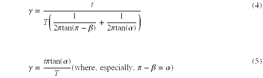
- As is recognized from the equations (4) and (5), α and β are constants, and therefore, the angle γ is expressed as a function of the rotation cycle T of the
rotary laser apparatus 151 and the time delay between detections of the two fan-shaped laser beams. If rotation of therotary laser 151 is somewhat irregular and this causes an error for the predetermined rotation cycle T, or rather, if some irregularity takes place in a single rotation whereas there is no error of the predetermined rotation cycle T, the time delay t between detections also has an error, which results in computing γ with an error. In a measurement of the horizontal plane where the two fan-shapedbeams - In a real construction site, the horizontal plane is often used for a reference plane, the arrangement in FIG. 17 where an error associated with the measurement in the horizontal reference plane is minimized is preferable to the arrangement in FIG. 2 where the fan-shaped
beams - The aforementioned principle of measuring angles by the
optical sensor 154 can apply to theoptical sensor 154 a that is designed to receive the fan-shapedbeams - (1.3.1.2) Principle of Measuring Angles by Means of Two Light Receiving Sections in Optical Sensor
- Discussed below will be a principle of measuring angles by two of the light receiving sections of the
optical sensor 154. With the two light receiving sections, a relative elevation of theoptical sensor 154 to therotary laser apparatus 151 and a distance between them can be obtained. As shown in FIG. 18, the light receiving sections are positioned vertically in series in theoptical sensor 154. - The two diverging or fan-shaped
beams beam 152 circularly sweeps at angle α to the horizontal plane while thebeam 153 does at angle β to the same. Thelight receiving sections beams light receiving sections optical sensor 154 detect a delay between times when the fan-shapedbeams optical sensor 154, as depicted in FIG. 19. - From the time delays t 1, t2, t3, and T detected in this way and constants α, β, and D, an elevation d1 of the
light receiving section 155 from the horizontal reference plane is given by the following equation (6) while an elevation d2 of thelight receiving section 156 is obtained by the following equation (7):
- Assuming now that γ 2 is an angle at which a straight line passing the
light receiving section 155 and the point C of emission of the fan-shaped laser beams meets the horizontal plane while γ1 is an angle at which a straight line passing thelight receiving section 156 and the point C meets the horizontal plane, γ2 and γ1 are obtained from the formula (4) as in the following equation (8):
- On the other hand, a distance L from the
rotary laser apparatus 151 to theoptical sensor 154 is expressed with the terms γ2, γ1, d1, and d2 as in the equations (10) and (11) as follows:
- Substituting the formulae (6) to (9) into the equations (10) and (11), the equations (12) and (13) are obtained as follows:

- Although either the equation (12) or the equation (13) can give the distance from the
rotary laser apparatus 151 and theoptical sensor 154, with given t2−t1=0, there is an operation of dividing zero in the equation (12) while, with given t3=0, there is an additional operation of dividing zero in the equation (13), and in either case, the formula including no such operation may be used. - Then, referring to FIG. 20, a case where the
optical sensor 154 is inclined at only an angle of ε will be simulated. In such a case, the time delays t1, t2, and t3 and the rotation cycle T are used to correct the inclination, and thus, the relative elevation of theoptical sensor 154 to therotary laser apparatus 151 and the distance between them can be obtained. - Under the condition of α+ε<90°, the fan-shaped beams are detected at the
light receiving sections optical sensor 154 in the same procedure as in FIG. 19. With given conditions of the time delays t1, t2, and t3, the rotation cycle T, the constants α and β, and the distance D between the two light receivingsections 155 an 156, vertical distances d1 and d2 from the horizontal reference plane to thelight receiving sections 
- The inclination angle ε of the
optical sensor 154 is obtained by the following formula (16):
- The distance L is obtained by substituting d 1, d2, γ1, and γ2 as given in the formulae (14), (15), (8), and (9) into the formulae (10) and (11).
- With referring to FIGS. 21 and 22, discussed below will be a case where the
light receiving sections - The two fan-shaped
beams beam 152 circularly sweeps at an angle α to the horizontal plane while thebeam 153 does at an angle β to the same. Theoptical sensor 154 includes the two light receivingsections - The fan-shaped beams, revolving under the conditions as mentioned above, are detected as illustrated in FIG. 22 when they sweep the
light receiving sections optical sensor 154. From the time delays t1, t2, t3, and T detected in this way and constants α, β, and D, a horizontal distance from the rotation center C of therotary laser apparatus 151 to thelight receiving sections optical sensor 154 can be given in the formula (17) as follows:
- where t 1=t3−t2.
- The vertical distances d1 and d2 from the horizontal reference plane to the
light receiving sections - d 1 =L tan(γ1) (18)
- d 2 =L tan(γ2) (19)
- Substituting the equations (8), (9) and (17) into the formulae (18) and (19) leads to the formulae (20) and (21) as follows:

- With given γ 2≈0 and γ1≈0, tan(γ)≈γ is satisfied, and therefore, the following formulae (22) and (23) are true:

- In the formulae (14), (15), (16), (22), and (23) where d1, d2 and ε are obtained includes, none of operation elements of terms include the rotation cycle T. This means that even if the rotation of the
rotary laser apparatus 151 is irregular and the predetermined rotation cycle T includes an error, the results of measurement would not be affected by such an error. Thus, when rotation irregularities that might affect the time delays t1, t2, and t3, do not take place in a short period of time when both the fan-shapedbeams light receiving sections optical sensor 154, measurements are accomplished without error. - This principle of measuring angles can apply to the fan-shaped
beams optical sensor 154 a. - (1.3.1.3) Principle of Measuring Positions of Optical Sensor
- When the
optical sensor 154 has the single light receiving section or two of the light receiving sections horizontally spaced from each other and when the two fan-shaped beams intersect with each other in the horizontal reference plane, detection of the time delay is insufficient to identify two positions that are vertically aligned and spaced equally from the horizontal reference plane. In this situation, in order to learn which side theoptical sensor 154 is located above or below the horizontal reference plane, theoptical sensor 154 must be moved up and down to check the state of receiving light. Specifically, if moving the optical sensor upward causes an increase in the time delay, theoptical sensor 154 is above the horizontal reference plane while, if moving the optical sensor downward causes a reduction of the time delay, theoptical sensor 154 is under the horizontal reference plane. When there are two or more of the light receiving sections spaced apart from one another at varied levels, respectively, it is possible to determine whether the optical sensor is located above or below the horizontal reference plane without the above-mentioned procedure. When properties such as polarization direction and frequency are useful to identify the two fan-shapedbeams - (1.3.1.4) Measurement Principle in the Event of Short Delay Between Detections of Diverging Beams
- As mentioned above, from the results of measurement and arithmetic operation on the delay t between times when two of the fan-shaped beams sweep the
optical sensor 154, a relative elevation of the optical sensor to therotary laser apparatus 151, a distance between them, and an inclination angle of the optical sensor are computed. When the light receiving section receives the two fan-shapedbeams beams - (1.3.2) Optical Sensor for Rotary Laser Apparatus Emitting Two Diverging Laser Beams of Different Polarizations
- Now discussed will be the
optical sensor 154 a designed to receive the two diverging or fan-shapedlaser beams optical sensor 154. - FIG. 24A is a front view of the
optical sensor 154 a while FIG. 24B is a sectional view of the same, taken along the line A-A of FIG. 24A. As shown in FIGS. 24A, 24B, alight receiving section 155 a of theoptical sensor 154 a includeslight receiving members polarized beam splitter 168 located in a previous stage to them while alight receiving section 156 a includeslight receiving members polarized beam splitter 169 located in a previous stage to them. Thepolarized beam splitters light receiving members light receiving members laser beams light receiving members light receiving members beam 152 a while thelight receiving members beam 153 a, and thus, the delay of time can be accurately determined. - Alternatively, a one-quarter (¼) wave plate (not shown) may be added to a trailing end of the optical path of the
rotary laser apparatus 151 a to emit circularly polarized laser beam while another one-quarter wave plate (not shown) may be placed in a previous stage to thepolarized beam splitters light receiving sections optical sensor 154 is inclined, thebeam splitters - (1.3.3) Optical Sensor Having a Single Light Receiving Section
- One of the light receiving sections in the
optical sensor - When the construction machine control system assuredly having its optical sensor always located above or below the horizontal reference plane is used, the above-mentioned procedure can be omitted. In this case, almost all the components of the optical sensor are similar to the aforementioned embodiments except that the single light receiving section is used.
- (1.3.4) Optical Sensor Having Three or More Light Receiving Sections
- Alternatively, there are three or more light receiving sections in the
optical sensor - FIGS. 25A to 25F illustrate an embodiment of an omnidirectional
optical sensor 154 b. As can be seen in FIG. 25A, the omnidirectionaloptical sensor 154 b is comprised of ahole 180, three light receiving sections 155 d, 155 e and 155 f, and anoptical sensor controller 177. The three light receiving sections 155 d, 155 e and 155 f are respectively attached to thepole 180 equidistant to each other, and theoptical sensor controller 177 is attached to a lower part of the pole. As recognized in FIGS. 25B to 25D, each of the light receiving sections 155 d, 155 e and 155 f has anannular Fresnel lens 176, anannular fiber sheet 175, and annularly chainedlight receiving elements 173, and these components are all concentrically deployed. Inside the annularly chainedlight receiving elements 173, a lightreceiving element controller 174. As shown in FIGS. 25E and 25F, theoptical sensor controller 177 has adisplay 157, analarm 161 such as a buzzer,entry keys 162, amemory 165, anarithmetic operation unit 166 determining a state of received light, and atransmitter 178 for external communication. - When the fan-shaped laser beam sweeps any of the light receiving sections, the cylindrical Fresnel lens focuses incident light onto the
light receiving elements 173 through thefiber sheet 175. Upon receiving the light, thelight receiving elements 173 transmit a signal due to the light to the light receivingelement controller 174. The lightreceiving element controllers 174 built in any of the light receiving sections 155 d, 155 e and 155 f transfer the signal to theoptical sensor controller 177. Theoptical sensor controller 177 processes the signal as theoptical sensor 154 does. - (1.4) Operation of Construction Machine Control System
- (1.4.1) Measurement of Elevations by Optical Sensor
- (1.4.1.1) Measurement by Means of Optical Sensor Having Two Light Receiving Sections
- A procedure of determining the relative elevation of the optical sensor to the
rotary laser apparatus 151 will be described. The elevation of theoptical sensor 154 is determined in the procedure as illustrated in FIG. 26. The fan-shapedbeams 152 and 13 emitted from therotary laser apparatus 151 are received at thelight receiving sections light receiving sections optical sensor 154, so as to compute the time delays t1, t2 and t3. - In the
arithmetic operation unit 166 determining a state of received light, the formula (16) is solved for the inclination angle ε from the elevation or depression angles α and β of the fan-shapedbeams arithmetic operation unit 166 further uses the equations (14) and (15) to obtain vertical distances d1 and d2 between the horizontal reference plane and thelight receiving sections sections memory 165, the time delays t1, t2 and t3, and the inclination angle ε previously computed. - The computation results d 1 and d2 are transferred to the
display 157 for indication, and thus, measurement of the relative elevation of theoptical sensor 154 to therotary laser apparatus 151 is accomplished. - (1.4.1.2) Measurement of an Elevation by Means of Optical Sensor Having a Single Light Receiving Section
- With reference to FIG. 27, discussed now will be a procedure of determining an elevation of the optical sensor having only a single light receiving section. When the fan-shaped
beams arithmetic operation unit 166 to compute the time delay t between detections of the beams. Substituting the time delay t, the rotation cycle T of the fan-shapedlaser beams display 157 for indication. A vertical distance or an elevation between the light receiving section and the horizontal plane is computed by the equation (18) and the distance L (a horizontal distance from the light receiving section to the rotation center C) that is obtained by the GPS as mentioned later. - (1.4.1.3) Measurement of an Elevation by Means of Optical Sensor Having Three or More Light Receiving Sections
- In the alternative embodiment where there are three or more light receiving sections, three of them receive the fan-shaped beams at the same time. Then, among data of received light, selected are two sets of the data characterized by no signal interference because of a sufficiently long delay of time between the detected fan-shaped beams. Computation after the selection of two sets of the data of received light is completely the same as the procedure illustrated in FIG. 26. In this case, however, the distance D between two of the selected light receiving sections is used.
- An alternative
rotary laser apparatus 151 a emits two laser beams of different polarizations, and an alternativeoptical sensor 154 a is capable of distinguishing the fan-shaped laser beams of different polarizations one from another. Hence, in the event of a short delay of time between detections of the laser beams, measurement can be accomplished with high accuracy. In this case, also, the measuring procedure is the same as that in the aforementioned embodiment. - (1.4.2) Measurement of Positions by Means of GPS
- With reference to FIG. 28, a method of determining positions by means of a GPS will be described. A construction machine such as a
bulldozer 502 has theoptical sensor 154, aGPS receiver 510, acontroller 650, adisplay 655, acontrol panel 656, ablade actuator 671, ahydraulic cylinder 573, and an attachment for leveling such as ablade 505. TheGPS receiver 510 is provided with aGPS antenna 509, areceiver 553, and asignal processor 654. Thecontroller 650 includes anarithmetic operation unit 651 and amemory 652. Theblade actuator 671 includes an electricalhydraulic circuit 672 and an electromagnetic valve (not shown). TheGPS base device 501 has aGPS base antenna 508 and awireless transmitter 557 and is located adjacent to therotary laser apparatus 151. - The
GPS antenna 509, which receives radio waves from a satellite, is attached to a place such as a roof of the bulldozer which is exposed to the radio waves without shield. On the other hand, theGPS base antenna 508 mounted on theGPS base device 501 also receives radio waves from the satellite. The radio waves receives at theGPS base antenna 508 is converted and then transmitted to thereceiver 553 mounted on theconstruction machine 502 via thewireless transmitter 557. The radio waves received at theGPS antenna 509 and thereceiver 553, respectively, are transferred to thesignal processor 654, amplified therein, and then, converted to a signal of a predetermined form. Thesignal processor 654 processes the radio waves received at theGPS antenna 509 and theGPS base antenna 508 and computes positions of those antennas in the horizontal plane and a distance between the antennas. From the computation results of the positions and distance, a distance from therotary laser apparatus 151 and theoptical sensor 154 mounted on theconstruction machine 502 is obtained through arithmetic operations. - Measurement of positions by means of the GPS includes kinematics, and any other methods of detecting a moving point on the real time basis.
- (1.4.3) Control of Construction Machine
- With reference to FIG. 28, control of the construction machine will be described.
- The
memory 652 incorporated in thecontroller 650 stores various data such as a landform based upon builder's working drawing, altitudes of the ground relative to two-dimensional coordinates, a position of therotary laser apparatus 151 in the horizontal plane, an elevation of therotary laser apparatus 151, and a height from theedge 505 a of the attachment blade to the reference position of theoptical sensor 154. Thememory 652 also stores a program of controlling theblade 505 in relation with the data on the position of theconstruction machine 502 within the horizontal plane, the elevation of the same, and the landform derived from the working drawing. If it is desirable to perform the above-mentioned arithmetic operations in some part of thecontroller 650 to obtain the elevation of theoptical sensor 154 from the time delay between detections of the fan-shaped beams, the arithmetic operations should be stored in thememory 652. Thecontroller 650 may be any device as represented by personal computer. - Position data (X1, Y1) of the
construction machine 102 and the elevation data H1 are input to thearithmetic operation unit 651 in thecontroller 650, where the former data is transferred from thesignal processor 654 and the latter data is received from the optical sensor. The control program of theblade 505 takes the input position data (X1, Y1) and the altitude data of the ground relative to the two-dimensional coordinates which is stored in the memory in advance, and then computes the desired ground level H2 in the position (X1, Y1). Theoptical sensor 154 is attached to the pole 506, and theoptical sensor 154 and the pole 506 together move upward and downward along with theblade 505. A distance H3 from theoptical sensor 14 to theedge 505 a of the blade is preliminarily stored in thememory 652. Subtracting the distance H3 from the elevation data H1, a current height H4 of theedge 505 a of the blade is obtained. After that, the desired ground level H2 and the height H4 of theblade edge 505 a are compared to calculate a displacement of theblade 505. - The displacement of the
blade 505 computed by thecontroller 650 is transferred to theblade actuator 671. Theblade actuator 671 opens and closes the electromagnetic valve of the electricalhydraulic circuit 671, depending upon an input of the displacement. Specifically, thearithmetic operation unit 651 gives the electricalhydraulic circuit 672 a control command of opening or closing the electromagnetic valve in accordance with a required sequence. Opening and closing the electromagnetic valve permits pressure oil to be supplied to or evacuated from thehydraulic cylinder 573, or rather is adjusts a flow rate of the pressure oil to move thehydraulic cylinder 573 in a required direction at a required speed, thereby moving theblade 505 up and down in any desired direction at any desired speed. A position of theblade 505 or a state of excavation is represented on thedisplay 655. - The actuation of the
blade 505 may be manually performed in some direct fashion. For instance, a difference of the position data (X1, Y1) of theconstruction machine 502, the height H4 of theblade edge 505 a, or the desired ground level H2 from the current height of the edge is represented on thedisplay 655. The operator of the construction machine manipulates thecontrol panel 656 while watching thedisplay 655, and hence, he or she can maneuver theblade 505 to level H4 to H2. In response to entries on thecontrol panel 656, entry signals are transferred to thearithmetic operation unit 651, which forces the electricalhydraulic circuit 672 andhydraulic cylinder 573 to move theblade 505. Without an aid of thearithmetic operation unit 651, the operator himself or herself may manipulate the blade actuator. - In the above embodiment, the
optical sensor 154 is attached to the pole 506 coupled to theblade 505, or alternatively, theoptical sensor 154 may be mounted on the body of the construction machine. In this situation, the distance H3 between theoptical sensor 154 and theblade 505 is varied, and hence, after determining extension and retraction of thehydraulic cylinder 573 or measuring a rotation angle of an arm supporting theblade 505, the distance H3 from the optical sensor to theblade 505 must be calculated again. The updated distance H3 is used in the arithmetic operations in thearithmetic operation unit 651 to renew the height H4. - Although the blade control of the bulldozer has been described, any other attachment such as roller may be used to reshape the ground.
- The control procedure as mentioned above may be effective without change in applications of the
optical sensor 154 a designed to receive the two fan-shaped laser beams of different polarizations and the optical sensor having three or more light receiving sections. - As has been described, with the construction machine control system according to the present invention, a task of leveling the ground is automated as required in the blueprint data, and the data represented on the
display 655 is useful to manual operation of leveling the ground. This enables any worker of poor expertise to easily manipulate the leveling machine in a construction site. - (1.4.4)
- In the aforementioned embodiment of the present invention, determination of positions in the horizontal plane by the GPS is performed on both the
construction machine 502 and theGPS receiver 510. In an ordinary use, however, therotary laser 151 is located in a fixed position without moving frequently, and therefore, once the position of therotary laser apparatus 151 is determined and entered as input data to thesignal processor 654 or thearithmetic operation unit 651 of theconstruction machine 502, theGPS 501 is needless or even may be omitted. - (1.4.5) Control over More than One Construction Machines
- Discussed below will be simultaneous use of more than one bulldozers to level the ground. As shown in FIG. 1, the
rotary laser apparatus 151 just emits the fan-shapedlaser beams GPS 501 simply transmits position data received at theGPS antenna 508, and installing anadditional construction machine 502 b with the same apparatuses enables theconstruction machine 502 b can be put under control in the same manner. Specifically, theoptical sensor 154 b mounted on theconstruction machine 502 b receives the fan-shapedlaser beams receiver 553 b receives radio wave from thewireless transmitter 557, theGPS antenna 509 b receives radio waves from a satellite, and so forth, and thus, completely the same control is attained. Similarly, a further increased number of the construction machine can be manipulated at the same time under control. - (1.4.6) Operation of Rotary Laser Apparatus
- The
rotary laser apparatus 151 does not have to emit fan-shaped laser beam through the whole circumferential trajectory of the revolution. In the above discussion, therotary laser apparatus 151 emits the laser beam throughout the circumferential trajectory, but the laser emission may be limited to a range defined by a working area of theconstruction machine 502 that receives the beam. In such a case, the laser illuminator 132 (see FIG. 5) should sometimes continually irradiate, but it may come up only for a restricted period of time when laser beam has to be directed to the construction machine, which leads to a reduced power consumption in the rotary laser apparatus. - To complete the above mentioned system structure, a communication means must be mounted on the
construction machines 502 to transmit position information of the construction machines to therotary laser apparatus 151. Therotary laser apparatus 151 should have a means for receiving the position information that is used to compute directions of the deployedconstruction machines 502. Laser beam should be emitted for a restricted period of time when therotary unit 105 of the projector 103 (see FIG. 4) turn to face a range covering the above mentioned directions, and for that purpose, a controller is provided to control rotation of themotor 106 and irradiation of thelaser illuminator 132. The laser emission range of therotary unit 105 is given by the encoder 117 (see FIG. 5). - With a similar system structure, the
motor 106 of therotary laser apparatus 151 may be activated so that the fan-shapedlaser beams construction machines 502. - (1.5) Other Advantages of the Construction Machine Control System of the Invention
- In a construction machine control system incorporated with the prior art rotary laser apparatus, it is merely determined whether the light receiving section is located in the horizontal plane onto which laser beams are directed or it is in an inclined plane, and therefore, the single laser projector is insufficient to level simultaneously two or more areas of different plane. On the contrary, the rotary laser apparatus used in the construction machine control system according to the present invention is capable of determining elevations in relation with the fan-shaped laser beams, and therefore, it enables more than one construction machines each having the
optical sensor 154 to simultaneously level the ground in several positions for any elevation as desired in a single circular sweep of the laser beams. - Moreover, with the construction machine control system according to the present invention, not only the ground of horizontal surfaces but of slopes or contours can be leveled easily and assuredly without expertise skills of the worker. Additionally, since the identical rotary laser apparatus controls more than one construction machines, undesired functions or malfunctions of the construction machines due to interference by other laser apparatus can be advantageously avoided.
- (2)
Embodiment 2 - In the following discussion, varied or modified points of a second preferred embodiment of the present invention from the first embodiment will be emphasized. Thus, any of particulars and details omitted herein has already been discussed in terms of the first embodiment.
- (2.1) Entire Structure of the Construction Machine Control System
- In the second preferred embodiment according to the present invention, as shown in FIG. 29, the
rotary laser apparatus 151 used in the first preferred embodiment is replaced with arotary laser apparatus 251 that emits two diverging or fan-shapedlaser beams optical sensor 154 in the first embodiment is replaced with anoptical sensor 254 that is capable of identifying the two fan-shaped laser beams of different wavelengths. Other components are almost the same as those in the first preferred embodiment. - ( 2.2)
- FIG. 30 shows the second preferred embodiment of the
rotary laser apparatus 251 that emits the fan-shaped laser beams of different wavelengths. In the second preferred embodiment of the present invention, components other than alaser projector 203 and itsrotary unit 205 are similar to those in the first embodiment. All the remaining components shown in FIG. 30 corresponding to their counterparts in the first embodiment are denoted by reference numerals all of which have a prefixed 2 to lower two digits instead of 1. - Although two fan-shaped beams of different polarities are used in the first embodiment, two fan-shaped beams of different wavelengths are used in the second embodiment.
- In the second embodiment, two fan-shaped
beams - FIG. 31 depicts the
laser projector 203 and therotary unit 205 in therotary laser apparatus 251 according to the present invention. As shown in FIG. 31, thelaser projector 203 is incorporated with twolaser illuminators laser illuminators laser illuminator 232 is denoted by broken line while a direction of polarization of the laser beam from thelaser illuminator 243 is designated by dot-dash line. The laser beams are guided into apolarized beam splitter 242. Thepolarized beam splitter 242 transmits laser light that is emitted from thelaser illuminator 232 and polarized in an X-direction, and it reflects laser light that is emitted from thelaser illuminator 243 and polarized in a Y-direction orthogonal to the X-direction. The laser beams transmitted through or reflected from thepolarized beam splitter 242, after collimated by a sharedcollimator lens 233, fall upon a one-quarter (¼)wave plate 240. The one-quarter wave plate 240 is oriented so that the laser beams from thelaser projector 203 are of reversely circular polarization to each other. The laser beams transmitted through the one-quarter wave plate 240 are, after falling on a one-quarter wave plate 239, linearly polarized. - Although the
rotary unit 205 is rotatably supported, this does not affect the laser beams emitted therefrom since they are circularly polarized, and the beams transmitted through the additional one-quarter wave plate 239 assume linear polarizations of which directions are determined by the one-quarter wave plate 239. The laser beams transmitted through the one-quarter wave plate 239 fall on thepolarized beam splitter 241. Thebeam splitter 241 reflects the laser light from thelaser illuminator 232 and transmits the laser light from thelaser illuminator 243. - Falling on the one-
quarter wave plate 238, the reflected laser light is circularly polarized and then reflected by acylinder mirror 236. Thecylinder mirror 236 is oriented so that the laser beam emitted from therotary unit 205 meets the horizontal plane at angel α. The laser light reflected from thecylinder mirror 236 is transmitted through the one-quarter wave plate 238 again, and when exiting, the resultant light is polarized in a direction turned by 90° from the light incident upon the plate Thus, the laser light is, after transmitted through the one-quarter wave plate 238, transmitted through thepolarized beam splitter 241 and then projected out of therotary unit 205. - The laser light transmitted through the
polarized beam splitter 241 is, after falling on the one-quarter wave plate 237, circularly polarized and then reflected from thecylinder mirror 235. Thecylinder mirror 235 is oriented so that the laser beam projected out of therotary unit 205 meets the horizontal plane at an angle β. The laser light reflected from thecylinder mirror 235 is transmitted through the one-quarter wave plate 237 again, and when exiting, the resultant light is polarized in a direction turned by 90° from the laser light incident upon the plate. In this way, the laser light is, after transmitted through the one-quarter wave plate 237, reflected by thepolarized beam splitter 241 and then projected out of therotary unit 205. - The
polarized beam splitter 242 may be a die clock mirror. - (2.3) Optical Sensor
- FIG. 32A is a front view showing an
optical sensor 254 in the second embodiment of the present invention, and FIG. 32B is a sectional view taken along the line A-A of FIG. 32A. All the components are similar to those in the first embodiment except the light receiving section which identifies light from different wavelengths. All the remaining components shown in FIGS. 32A, 32B corresponding to their counterparts in the first embodiment are denoted by reference numerals all of which have a prefixed 2 to lower two digits instead of 1. - As shown in FIGS. 32A, 32B, the
optical sensor 254 in the second embodiment identifies and distinguishes the fan-shapedbeams light receiving sections 255 and 256 from their respective wavelengths. Thelight receiving sections 255 and 256 have die clock mirrors 268 and 269, respectively, that transmit or reflect laser light, depending upon the wavelengths of the incident laser beams.Light receiving sections sections - (2.4) Operation of the Second Embodiment of the Construction Machine Control System
- The measurement procedure explained in terms of the first embodiment of the present invention may be used without change and modification in an application of the second embodiment of the present invention, namely, a construction
machine control system 200. - (3)
Embodiment 3 - In the following discussion, varied or modified points of a second preferred embodiment of the present invention from the first embodiment will be emphasized. Thus, any of particulars and details omitted herein has already been discussed in terms of the first embodiment.
- (3.1) Entire Structure of the Construction Machine Control System
- The third embodiment of the construction machine control system according to the present invention will be outlined. As shown in FIG. 33, the third preferred embodiment, namely, a construction
machine control system 300 includes therotary laser apparatus 351 and theoptical sensor 354. Therotary laser apparatus 351 rotates about the point C while emitting diverging or fan-shapedbeams optical sensor 354 receives the fan-shapedbeams - (3.2) Rotary Laser Apparatus Emitting Two Fan-Shaped Laser Beams Modulated into Different Frequencies
- The third preferred embodiment, or namely, the
rotary laser apparatus 351 is shown in FIG. 34. All the other components other than alaser projector 303 and arotary unit 305 are similar to those in the first embodiment. In the third embodiment, all the remaining components shown in FIG. 33 corresponding to their counterparts in the first embodiment are denoted by reference numerals all of which have a prefixed 3 to lower two digits instead of 1. - Although the two fan-shaped beams of different polarizations are used in the first embodiment, two fan-shaped beams modulated into different frequencies are used in the third embodiment.
- In the third embodiment, two fan-shaped
beams rotary laser apparatus 351 are modulated to be different in frequency, so that the two beams can be distinguished from each other. Modified in this fashion, the similar effects to those attained by using the two fan-shaped beams of different polarizations can be obtained. - The
laser projector 303 and therotary unit 305 of therotary laser apparatus 351 are shown in FIG. 35. As can be seen in FIG. 35, thelaser projector 303 has twolaser illuminators laser illuminators laser illuminator 332 is denoted by broken line while a polarization direction of laser light emitted from thelaser illuminator 343 is designated by dot-dash line. Optical system projecting laser light from thelaser illuminators - (3.3) Optical Sensor
- FIG. 36A is a front view showing an
optical sensor 354 in the third embodiment of the present invention, and FIG. 36B is a sectional view taken along the line A-A of FIG. 36A. All the components are similar to those in the first embodiment except the light receiving section which identifies light from varied frequencies. All the remaining components shown in FIGS. 36A, 36B corresponding to their counterparts in the first embodiment are denoted by reference numerals all of which have a prefixed 3 to lower two digits instead of 1. - As shown in FIGS. 36A, 36B, the
optical sensor 354 in the third embodiment has an arithmetic operation unit 366 that judges a state of received light, and it is used to identify and distinguish the fan-shapedbeams light receiving sections light receiving sections beam splitters Light receiving sections beam splitters sections - (3.4) Operation of the Third Embodiment of the Construction Machine Control System
- The measurement procedure explained in terms of the first embodiment of the present invention may also be used without change and modification in an application of the third embodiment of the present invention, namely, a construction
machine control system 300. - (3.4.1) Modulation of Diverging Beams and Detection of Modulated Beams
- A manner of modulation of the two diverging or fan-shaped
beams beams beams light receiving sections optical sensor 354. Detection signals of the fan-shapedbeams beams - The optical sensor is provided with a modulated frequency determining circuit, and the fan-shaped
beams beams - Alternatively, as shown in FIG. 39, the fan-shaped
beams - Further alternatively, a modulation of combined modulation properties as in FIGS. 37 and 39 may be applied. Specifically, as shown in FIG. 41, the fan-shaped
beams beams beams - (4) Other Embodiments
- (4.1) Variations of the Fan-Shaped Beams
- Although in all the aforementioned embodiments, the rotary laser apparatus that emits two fan-shaped beams is used, the construction machine control system may be completed with an alternative rotary laser apparatus that emits three or more fan-shaped laser beams simultaneously. In such a situation, two of the fan-shaped beams are appropriately selected to take a measurement in completely the same manner as in the aforementioned embodiments.
- FIGS. 42A to 42J depict exemplary emission patterns of the fan-shaped beams. FIGS. 42A to 42J show cross sections of the fan-shaped beams viewed from the optical sensor where dot-dash line denotes the horizontal reference plane. In terms of the aforementioned embodiments, FIGS. 42C to 42J depicts various emission patterns of the three or more fan-shaped beams. Intersections of the fan-shaped beams with the horizontal reference plane are preferably spaced equidistant from one another. As for the emission patterns in FIG. 42A to FIG. 42C, the fan-shaped beams are not overlapped when the optical sensor is in the horizontal plane, and hence, the time delay among detections can be accurately determined without modulating the fan-shaped beams into different polarizations from one another.
- Also, when emitted in the patterns as in FIGS. 42C to 42G and FIGS. 42I and 42J, three of the fan-shaped beams are sequentially detected one after another with time delays that are equivalent to each other if counted in the horizontal plane, and this is why finding the horizontal reference plane is facilitated. Also, as stated above, two of the fan-shaped laser beams may be appropriately selected among all to take a measurement in completely the same manner as in the aforementioned embodiments; that is, since a rate of the two time delays can be correlated with only one combination of an angular position of the optical sensor relative to the horizontal plane, finding the rate of one of the time delays to the other can directly lead to the angle of the optical sensor relative to the horizontal plane. When only two fan-shaped laser beams are considered, the rotary cycle T is required to obtain the angles, but not if three or more fan-shaped beams are used. This proves that the aforementioned embodiments can attain an accurate measurement without being affected by a rotation error of the rotary laser apparatus.
- Patterned as in FIG. 42H, a sequential sensing of four of the fan-shaped beams produces three delays of time from one detection to another, and averaging them results in enhancing measurement accuracy. Patterning the beams as in FIGS. 42I and 42J, sensitivity of the optical sensor is varied from detections of light in the vicinity of the horizontal plane to detection in other areas. For instance, although a minor deviation of the optical sensor from the horizontal plane causes a large variation in the time delays between detections in the vicinity of the horizontal plane, a vertical displacement of the optical sensor does not influence the delays so much at levels far apart from the horizontal plane. In this way, the horizontal reference plane can be accurately detected from the time delays between detections at the optical sensor. In this specification, laser beams, like laser beams in the middle in FIGS. 42I and 42J, spreading into a curved or creased plane are referred to as fan-shaped beams. As for curved or creased fan-shaped beams, an inclination angle of the fan-shaped laser beam is an inclination of tangent passing an arbitrary point on the curved or creased plane.
- A computation of finding an elevation from the horizontal reference plane based upon the received fan-shaped beams is carried out by repeating the aforementioned computation procedure in terms of arbitrary two of the fan-shaped beams for the emission patterns in FIGS. 42C to 42H. As to the emission patterns in FIGS. 42I and 42J, the computation procedure is appropriately changed to obtain the elevation from the horizontal reference plane.
- The emission patterns are all implemented, as shown in FIG. 6, by providing an appropriate diffraction grating across an optical path in the optical system emitting the fan-shaped beams. Without the diffraction grating, the aforementioned emission patterns can also be created. FIG. 43 shows an embodiment of a
laser projector 403 and arotary unit 405 of the rotary laser apparatus that produces the fan-shaped beams patterned as in FIG. 42C. In FIG. 43, all the components corresponding to their respective counterparts of the first embodiment are denoted by reference numerals having aprefix 4 to lower two digits instead of 1. Laser beam, after emitted from the laser illuminator, passes acollimator lens 433 and one-quarter (¼)wave plates polarized beam splitter 441. The laser beam incident upon thepolarized beam splitter 441, which, in part, is transmitted through the same, is transmitted through a one-quarter wave plate 437 and reflected by acylinder mirror 435, and thereafter, transmitted through the one-quarter wave plate 437 again to fall on thepolarized beam splitter 441. The incident laser light is reflected by thebeam splitter 441, and thus, a fan-shapedbeam 453 is projected, meeting the horizontal reference plane at an inclination of β. - On the other hand, the laser light, which exits the one-
quarter wave plate 439 and falls on thepolarized beam splitter 441, is in part reflected by thebeam splitter 441 and then falls upon a one-quarter wave plate 438. The laser light incident upon the one-quarter wave plate 438, after passing the same, is transmitted through a deflectingprism 460 and then reflected by acylinder mirror 436. Thecylinder mirror 436 is oriented so that it projects fan-shaped beam diverging vertically. The laser light reflected by thecylinder mirror 436 reenters the deflecting prism and is shaped into two fan-shaped beams that diverge vertically. The fan-shaped beams are transmitted through the one-quarter wave plate 438 and thebeam splitter 441, and thus, fan-shapedbeams 452 a and 452 ba are projected. - With reference to FIG. 44, discussed now will be varied or modified embodiments of the laser illuminator and the rotary unit of the rotary laser apparatus that emits the diverging or fan-shaped beams patterned as in FIG. 42C. A
laser projector 503 of this embodiment includes alaser illuminator 532 and acollimator lens 533. Arotary unit 505 of this embodiment has three equi-magnification beam expanders cylindrical lenses mirrors - Laser light emitted from the
laser illuminator 532 is collimated by thecollimator lens 533. The laser light transmitted through thecollimator lens 533 falls on the three equi-magnification beam expander rotary unit 505. The laser beam incident upon the equi-magnification beam expander 562 is declined at a predetermined ratio. The laser light transmitted through the equi-magnification beam expander beams cylindrical lens cylindrical lens mirrors - In this situation, since the laser light is once reflected by the mirror 566 after transmitted through the equi-magnification beam expander 562, a deflection angle of the laser beam is simply dependent upon a deflection angle in transmission through the
rotary unit 505. Thus, emission directions of the fan-shapedbeams laser illuminator 503 and therotary unit 505. In some application, for the purpose of shielding from light other than laser beam emitted from thelaser projector 503 and entering the equi-magnification beam expander 562, a shield mask (not shown) may be provided beneath the equi-magnification beam expander 562. Alternatively, for the purpose of shielding from light other than laser beam emitted from thelaser illuminator 532 and entering thecollimator lens 533, a shield mask (not shown) may be provided between thelaser illuminator 532 and thecollimator lens 533. - With reference to FIGS. 45 and 46, described below will be additional varied or modified embodiments of the laser illuminator and the rotary unit of the rotary laser apparatus that emits the fan-shaped laser beams patterned as in FIG. 42C. A
laser projector 603 of this embodiment includes alaser illuminator 632 and acollimator lens 633. Arotary unit 605 of this embodiment has ashield mask 672 having threeapertures pentaprism 674 deflecting laser light that has passed themask 672,cylindrical lenses pentaprism 674 to spread beam into diverging fan-like shape, and awedge prism 678 deflecting and collimating laser beam from thepentaprism 674. - Laser light emitted from the
laser illuminator 632 is collimated by thecollimator lens 633. The laser light transmitted through thecollimator lens 633 falls on theshield mask 672 in therotary unit 605. The laser beam, after passing theaperture 672 a in themask 672, falls on thepentaprism 674 and is deflected therein. In FIG. 46, the laser beam from theaperture 672 a directly falls on the bottom of thepentaprism 674, which deflects the beam by 90° to let it exit from its vertical face. The laser light falls on thecylindrical lens 676 attached to the vertical face of thepentaprism 674, and it is spread into fan-shapedbeam 653 which meets the horizontal plane at a predetermined inclination angle. On the other hand, the laser light that passes theaperture cylindrical lens 675 attached to the bottom of thepentaprism 674, and the resultant separate laser beams are spread into diverging fan-like shape and then deflected by 90° in thepentaprism 674. The laser beams are directed to thewedge prism 678 that is attached to a lower portion of thecylindrical lens 676 mounted on a vertical face of thepentaprism 674, and then horizontally deflected, and thus, fan-shapedbeams - In this situation, the laser beams are respectively reflected twice in the
pentaprism 674, and angles at which the laser beams are deflected simply depend upon a deflection angle in transmission through thepentaprism 674. Thus, directions of the emergent fan-shapedbeams laser projector 603 and therotary unit 605. In some application, for the purpose of blocking light other than the laser beams emitted from thelaser illuminator 632 and entering thecollimator lens 633, a shield mask (not shown) may be provided between thelaser illuminator 632 and thecollimator lens 633. - (4.2) Other Variations and Modifications of the Construction Machine Control System
- Various embodiments of the construction machine control system have been described, emphasizing specific examples such as the construction machine control systems including the rotary laser apparatuses that respectively emit two fan-shaped laser beams intersecting each other in and outside the horizontal reference plane, the rotary laser apparatus that emits three or more fan-shaped laser beams, the rotary laser apparatus that emits two fan-shaped laser beams polarized differently, the rotary laser apparatus that emits laser beams modulated to have different frequencies or wavelengths, respectively, the optical sensor having a single light receiving section, the optical sensor that has more than one light receiving sections located vertically or horizontally, the optical sensor capable of distinguishing differently polarized fan-shaped beams, and an optical sensor capable of distinguishing fan-shaped beams modulated to have different frequencies or wavelengths, respectively. Any person having ordinary skills in the art would envision appropriately combined revisions of the aforementioned embodiments of the construction machine control system without departing true scope of the invention as defined in the appended claims.
- In accordance with the present invention, a single rotary laser apparatus permits control over more than one construction machines so that the construction machines can level the ground at varied levels simultaneously. Additionally, it also permits workers to manipulate the construction machines and grade the inclined ground efficiently regardless of their expertise level of conducting such a task, and it further permits control over more than one construction machines to grade or shape slopes of different inclinations simultaneously.
Claims (14)
1. A system of controlling construction machines, comprising
a rotary laser apparatus that emits two or more fan-shaped laser beams while rotating the laser beams about a given axis, the two or more fan-shaped laser beams diverging in a plane other than horizontal plane, one of the fan-shaped laser beams is different in inclination angle from the other,
an optical sensor mounted on a construction machine for receiving the fan-shaped laser beams,
a GPS receiver mounted on the construction machine for determining a position of the construction machine, and
an arithmetic operation device provided in the construction machine,
the arithmetic operation device receiving a detection signal from the GPS receiver to determine the position of the construction machine, and
the arithmetic operation device computing and producing a control signal over the construction machine from a delay of time between detections of the fan-shaped laser beams received at the optical sensor.
2. A system according to claim 1 , wherein the arithmetic operation device computes and produces the control signal over the construction machine on the basis of detection signals from the optical sensor and the GPS receiver besides a signal on topographic data.
3. A system according to claim 1 , further comprising an actuator unit activated in response to the control signal incorporated in the construction machine.
4. A system according to claim 1 , wherein the rotary laser apparatus is settled in a known position, and the arithmetic operation device computes the control signal in terms of data of the known position.
5. A system according to claims 1, further comprising a GPS base apparatus determining a position of the rotary laser apparatus, the arithmetic operation device being capable of determining a relative position of the construction machine to the rotary laser apparatus.
6. A system according to claim 1 , wherein the two or more fan-shaped laser beams intersect one another in the horizontal plane.
7. A system according to claim 1 , wherein the rotary laser apparatus emits two or more fan-shaped laser beams that are different in polarization from each other.
8. A system according to claim 1 , wherein the rotary laser apparatus emits two or more fan-shaped laser beams that are modulated into different frequencies from one another.
9. A system according to claims 1, wherein the rotary laser apparatus emits two or more fan-shaped laser beams that are different in wavelength from one another.
10. A system according claims 1, wherein the optical sensor has two light receiving sections that respectively receive the fan-shaped laser beams.
11. A system according to claim 1 , wherein the optical sensor has three or more light receiving sections that respectively receive the fan-shaped laser beams.
12. A system according to claim 1 , wherein the rotary laser apparatus emits fan-shaped laser beams each of which has an intensity varied from one part to another.
13. A system according to claim 1 , wherein the rotary laser apparatus emits three or more fan-shaped laser beams that intersect with the horizontal plane equidistant from one another.
14. A system according to claim 13 , wherein the rotary laser apparatus emits three or more fan-shaped laser beams that would not intersect one another within a range where they are optically received.
Applications Claiming Priority (2)
| Application Number | Priority Date | Filing Date | Title |
|---|---|---|---|
| JP2002-011538 | 2002-01-21 | ||
| JP2002011538A JP3816806B2 (en) | 2002-01-21 | 2002-01-21 | Construction machine control system |
Publications (2)
| Publication Number | Publication Date |
|---|---|
| US20030137658A1 true US20030137658A1 (en) | 2003-07-24 |
| US6947820B2 US6947820B2 (en) | 2005-09-20 |
Family
ID=19191686
Family Applications (1)
| Application Number | Title | Priority Date | Filing Date |
|---|---|---|---|
| US10/337,873 Expired - Lifetime US6947820B2 (en) | 2002-01-21 | 2003-01-08 | Construction machine control system |
Country Status (3)
| Country | Link |
|---|---|
| US (1) | US6947820B2 (en) |
| JP (1) | JP3816806B2 (en) |
| CN (1) | CN1221715C (en) |
Cited By (46)
| Publication number | Priority date | Publication date | Assignee | Title |
|---|---|---|---|---|
| EP1524495A1 (en) | 2003-10-14 | 2005-04-20 | Kabushiki Kaisha Topcon | Laser irradiating system |
| EP1580570A2 (en) | 2004-03-26 | 2005-09-28 | Topcon GPS LLC | Estimation and resolution of carrier-wave ambiguities in a position navigation system |
| EP1580527A2 (en) * | 2004-03-23 | 2005-09-28 | Kabushiki Kaisha Topcon | Laser measuring method and laser measuring system |
| US20050274879A1 (en) * | 2004-06-15 | 2005-12-15 | Kazuki Osaragi | Position measuring system |
| US20060012777A1 (en) * | 2004-07-13 | 2006-01-19 | Talbot Nicholas C | Combination laser system and global navigation satellite system |
| US20060041361A1 (en) * | 2004-08-23 | 2006-02-23 | Ivan Matrosov | Dynamic stabilization and control of an earthmoving machine |
| WO2006022879A1 (en) * | 2004-07-23 | 2006-03-02 | Trimble Navigation Limited | Combination laser detector and global navigatino satellite receiver system |
| AU2005232270B1 (en) * | 2005-11-10 | 2006-07-20 | Kevin James Moller | A Laser Leveling System |
| WO2007027383A2 (en) * | 2005-08-27 | 2007-03-08 | Trimble Navigation Ltd. | Method for augmenting radio positioning system using single fan laser |
| US20070052950A1 (en) * | 2004-07-13 | 2007-03-08 | Trimble Navigation Limited | Navigation system using both GPS and laser reference |
| US20070076188A1 (en) * | 2005-09-30 | 2007-04-05 | Kabushiki Kaisha Topcon | Laser level detection system |
| US7222035B1 (en) | 2004-11-17 | 2007-05-22 | Topcon Gps, Llc | Method and apparatus for determining changing signal frequency |
| US7336349B1 (en) * | 2006-11-09 | 2008-02-26 | The Boeing Company | Systems and methods for determining a configuration of a barge complex |
| US20080109141A1 (en) * | 2006-11-08 | 2008-05-08 | Caterpillar Trimble Control Technologies Llc. | Systems and methods for augmenting an inertial navigation system |
| US20080244920A1 (en) * | 2004-12-28 | 2008-10-09 | Leica Geosystems Ag | Method and Rotating Laser for Determining an Item of Attitude Information of at Least One Object |
| US20080252907A1 (en) * | 2007-04-16 | 2008-10-16 | Willibald Sehr | Apparatus and Method for Determining an Elevation of Working Tools Based on a Laser System |
| US20080285057A1 (en) * | 2003-12-22 | 2008-11-20 | Eyepoint Ltd | High Precision Wide-Angle Electro-Optical Positioning System and Method |
| US7857071B1 (en) | 2005-08-05 | 2010-12-28 | Topcon Positioning Systems, Inc. | Grade indicator for excavation operations |
| CN102042827A (en) * | 2009-10-19 | 2011-05-04 | 天宝导航有限公司 | Multiple-wavelength laser receiver |
| DE102010060654A1 (en) * | 2010-11-18 | 2012-05-24 | Status Pro Maschinenmesstechnik Gmbh | Method for measuring horizontal surface of component or structure during construction of e.g. crane, involves receiving data transmitted by positioning system by receivers for determining coordinates, and evaluating data by computing device |
| US20120130598A1 (en) * | 2010-11-22 | 2012-05-24 | Ramadev Burigsay Hukkeri | Object detection system having adjustable focus |
| US20120127030A1 (en) * | 2009-01-27 | 2012-05-24 | Ohio University | Tight optical integration (toi) of images with gps range measurements |
| US20120130588A1 (en) * | 2010-11-22 | 2012-05-24 | Ramadev Burigsay Hukkeri | Object detection system having interference avoidance strategy |
| WO2012078549A1 (en) * | 2010-12-08 | 2012-06-14 | Rick Grover | Systems and methods for laying out and installing a solar panel array |
| CN103392533A (en) * | 2013-07-04 | 2013-11-20 | 北京农业智能装备技术研究中心 | Bed arranging machine and control method thereof |
| CN103938671A (en) * | 2013-04-10 | 2014-07-23 | 常州华达科捷光电仪器有限公司 | Excavator guiding system and method |
| US8848180B1 (en) | 2013-09-05 | 2014-09-30 | Laserline Mfg., Inc. | Reference systems for indicating slope and alignment and related devices, systems, and methods |
| DE112007000285B4 (en) * | 2006-02-01 | 2014-10-23 | Trimble Navigation Ltd. | Position indicating guide control system and method for the same |
| DE112008003444B4 (en) * | 2008-01-15 | 2015-12-17 | Trimble Navigation Ltd. | System for loader |
| EP2551637A4 (en) * | 2010-03-25 | 2017-10-04 | Kabushiki Kaisha Topcon | Rotating laser device and rotating laser system |
| USD885867S1 (en) | 2018-12-28 | 2020-06-02 | Topcon Positioning Systems, Inc. | Adaptor |
| USD885866S1 (en) | 2018-12-28 | 2020-06-02 | Topcon Positioning Systems, Inc. | Mount base |
| US20200208380A1 (en) * | 2018-12-28 | 2020-07-02 | Topcon Positioning Systems, Inc. | Construction machine sensor system |
| USD896114S1 (en) * | 2018-12-28 | 2020-09-15 | Topcon Positioning Systems, Inc. | Sensor housing |
| USD896667S1 (en) | 2018-12-28 | 2020-09-22 | Topcon Positioning Systems, Inc. | Sensor housing |
| USD896669S1 (en) | 2018-12-28 | 2020-09-22 | Topcon Positioning Systems, Inc. | Sensor housing |
| USD896664S1 (en) | 2018-12-28 | 2020-09-22 | Topcon Positioning Systems, Inc. | Sensor housing |
| USD896662S1 (en) | 2018-12-28 | 2020-09-22 | Topcon Positioning Systems, Inc. | Sensor housing |
| USD896663S1 (en) | 2018-12-28 | 2020-09-22 | Topcon Positioning Systems, Inc. | Sensor housing |
| USD896668S1 (en) | 2018-12-28 | 2020-09-22 | Topcon Positioning Systems, Inc. | Sensor housing |
| USD896670S1 (en) | 2018-12-28 | 2020-09-22 | Topcon Positioning Systems, Inc. | Sensor housing |
| USD896665S1 (en) | 2018-12-28 | 2020-09-22 | Topcon Positioning Systems, Inc. | Sensor housing |
| USD896666S1 (en) | 2018-12-28 | 2020-09-22 | Topcon Positioning Systems, Inc. | Sensor housing |
| USD897225S1 (en) | 2018-12-28 | 2020-09-29 | Topcon Positioning Systems, Inc. | Sensor housing |
| CN112639225A (en) * | 2019-03-01 | 2021-04-09 | 日立建机株式会社 | Working machine |
| US20210372081A1 (en) * | 2020-05-28 | 2021-12-02 | Jiangsu Xcmg Construction Machinery Research Institute Ltd. | Leveling control method, device and system, and motor grader |
Families Citing this family (26)
| Publication number | Priority date | Publication date | Assignee | Title |
|---|---|---|---|---|
| JP2004212058A (en) * | 2002-12-26 | 2004-07-29 | Topcon Corp | Working position measuring apparatus |
| JP4279111B2 (en) * | 2003-10-14 | 2009-06-17 | 株式会社トプコン | Measuring method and measuring system |
| JP4398314B2 (en) * | 2004-07-09 | 2010-01-13 | 株式会社 ソキア・トプコン | Surveying instrument and marking point transfer processing program |
| CN100357528C (en) * | 2004-12-31 | 2007-12-26 | 刘景才 | Blade machine bucket height automatic adjusting method and device thereof |
| US20080047170A1 (en) * | 2006-08-24 | 2008-02-28 | Trimble Navigation Ltd. | Excavator 3D integrated laser and radio positioning guidance system |
| US7970519B2 (en) * | 2006-09-27 | 2011-06-28 | Caterpillar Trimble Control Technologies Llc | Control for an earth moving system while performing turns |
| US8073566B2 (en) | 2007-04-05 | 2011-12-06 | Power Curbers, Inc. | Automated stringline installation system |
| JP2007271627A (en) * | 2007-04-26 | 2007-10-18 | Topcon Corp | Work position measuring device |
| US9250328B2 (en) * | 2009-09-30 | 2016-02-02 | Javad Gnss, Inc. | Graphics-aided remote position measurement with handheld geodesic device |
| US20120299936A1 (en) | 2009-09-30 | 2012-11-29 | Javad Gnss, Inc. | Graphics-aided remote position measurement with handheld geodesic device |
| US20110153170A1 (en) * | 2009-12-23 | 2011-06-23 | Caterpillar Inc. | System And Method For Controlling An Implement To Maximize Machine Productivity And Protect a Final Grade |
| US8125376B1 (en) | 2010-08-30 | 2012-02-28 | Javad Gnss, Inc. | Handheld global positioning system device |
| JP5328830B2 (en) * | 2011-03-24 | 2013-10-30 | 株式会社小松製作所 | Hydraulic excavator calibration apparatus and hydraulic excavator calibration method |
| JP5237408B2 (en) * | 2011-03-24 | 2013-07-17 | 株式会社小松製作所 | Hydraulic excavator calibration system and calibration method |
| JP6016264B2 (en) | 2011-09-26 | 2016-10-26 | ジャバド ジーエヌエスエス, インコーポレイテッド | Visual stakeout |
| CN102518160B (en) * | 2011-12-26 | 2014-11-12 | 中国农业机械化科学研究院 | Elevation control method and system based on global position system (GPS) and laser technology |
| US9279679B2 (en) | 2012-09-12 | 2016-03-08 | Kabushiki Kaisha Topcon | Construction machine control method and construction machine control system |
| US8788154B2 (en) * | 2012-09-12 | 2014-07-22 | Kabushiki Kaisha Topcon | Construction machine control method and construction machine control system |
| JP6051751B2 (en) * | 2012-10-05 | 2016-12-27 | Jfeスチール株式会社 | Method and apparatus for detecting position and orientation of metal plate, and method for inspecting metal plate |
| EP2725149A1 (en) | 2012-10-24 | 2014-04-30 | Hexagon Technology Center GmbH | Machine control system for a wheel loader comprising a grading blade |
| CN103046592A (en) * | 2013-01-21 | 2013-04-17 | 潍柴动力股份有限公司 | Hybrid power bulldozer and leveling system and leveling method thereof |
| US9631329B2 (en) * | 2014-12-19 | 2017-04-25 | Wirtgen Gmbh | Frame distortion control |
| JP7208699B2 (en) * | 2017-11-29 | 2023-01-19 | 日立建機株式会社 | How to set the antenna height |
| US10859702B1 (en) * | 2017-12-21 | 2020-12-08 | Facebook Technologies, Llc | Positional tracking using retroreflectors |
| US11125877B2 (en) * | 2018-10-24 | 2021-09-21 | Bryan Jayvon McGill | Multi-directional laser level |
| CN109610539B (en) * | 2018-11-30 | 2020-12-25 | 中船重工中南装备有限责任公司 | Track chassis cutter-suction type dredging robot with self-deviation correction function |
Citations (13)
| Publication number | Priority date | Publication date | Assignee | Title |
|---|---|---|---|---|
| US4273196A (en) * | 1978-05-16 | 1981-06-16 | Kabushiki Kaisha Komatsu Seisakusho | Automatic control system for maintaining blade in predetermined relationship to laser beam |
| US4679940A (en) * | 1984-08-01 | 1987-07-14 | Hamar M R | Control system for a continuous cell target readout in a laser measurement system |
| US5100229A (en) * | 1990-08-17 | 1992-03-31 | Spatial Positioning Systems, Inc. | Spatial positioning system |
| US5572809A (en) * | 1995-03-30 | 1996-11-12 | Laser Alignment, Inc. | Control for hydraulically operated construction machine having multiple tandem articulated members |
| US5600436A (en) * | 1994-01-05 | 1997-02-04 | Caterpillar Inc. | Apparatus and system for determining terrestrial position |
| US5742387A (en) * | 1995-12-21 | 1998-04-21 | Ammann Lasertechnik Ag | Laser beam levelling device and process for operating a laser beam levelling device and associated contrivance |
| US5848485A (en) * | 1996-12-27 | 1998-12-15 | Spectra Precision, Inc. | System for determining the position of a tool mounted on pivotable arm using a light source and reflectors |
| US6052181A (en) * | 1998-07-01 | 2000-04-18 | Trimble Navigation Limited | Multiple simultaneous laser-reference control system for construction equipment |
| US20020154948A1 (en) * | 2001-01-17 | 2002-10-24 | Topcon Laser Systems, Inc. | Automatic mode selection in a controller for grading implements |
| US20020170210A1 (en) * | 1999-06-15 | 2002-11-21 | Kabushiki Kaisha Topcon | Laser beam detecting device for a construction machine |
| US6535282B2 (en) * | 2000-10-30 | 2003-03-18 | Arc Second, Inc. | Position measurement system and method using cone math calibration |
| US6630993B1 (en) * | 1999-03-22 | 2003-10-07 | Arc Second Inc. | Method and optical receiver with easy setup means for use in position measurement systems |
| US6782644B2 (en) * | 2001-06-20 | 2004-08-31 | Hitachi Construction Machinery Co., Ltd. | Remote control system and remote setting system for construction machinery |
Family Cites Families (5)
| Publication number | Priority date | Publication date | Assignee | Title |
|---|---|---|---|---|
| US5294970A (en) | 1990-12-31 | 1994-03-15 | Spatial Positioning Systems, Inc. | Spatial positioning system |
| JP3401959B2 (en) * | 1994-10-27 | 2003-04-28 | 株式会社ニコン | Level sensor |
| JPH09282706A (en) * | 1996-04-18 | 1997-10-31 | Olympus Optical Co Ltd | Optical sensor |
| JP3385218B2 (en) * | 1998-09-16 | 2003-03-10 | 三菱電機株式会社 | Laser beam optical axis deviation detector |
| JP2001116510A (en) * | 1999-10-14 | 2001-04-27 | Isamu Miyamoto | Welding part monitoring method and welding part monitoring apparatus for laser beam welding |
-
2002
- 2002-01-21 JP JP2002011538A patent/JP3816806B2/en not_active Expired - Fee Related
-
2003
- 2003-01-08 US US10/337,873 patent/US6947820B2/en not_active Expired - Lifetime
- 2003-01-21 CN CNB031017517A patent/CN1221715C/en not_active Expired - Fee Related
Patent Citations (13)
| Publication number | Priority date | Publication date | Assignee | Title |
|---|---|---|---|---|
| US4273196A (en) * | 1978-05-16 | 1981-06-16 | Kabushiki Kaisha Komatsu Seisakusho | Automatic control system for maintaining blade in predetermined relationship to laser beam |
| US4679940A (en) * | 1984-08-01 | 1987-07-14 | Hamar M R | Control system for a continuous cell target readout in a laser measurement system |
| US5100229A (en) * | 1990-08-17 | 1992-03-31 | Spatial Positioning Systems, Inc. | Spatial positioning system |
| US5600436A (en) * | 1994-01-05 | 1997-02-04 | Caterpillar Inc. | Apparatus and system for determining terrestrial position |
| US5572809A (en) * | 1995-03-30 | 1996-11-12 | Laser Alignment, Inc. | Control for hydraulically operated construction machine having multiple tandem articulated members |
| US5742387A (en) * | 1995-12-21 | 1998-04-21 | Ammann Lasertechnik Ag | Laser beam levelling device and process for operating a laser beam levelling device and associated contrivance |
| US5848485A (en) * | 1996-12-27 | 1998-12-15 | Spectra Precision, Inc. | System for determining the position of a tool mounted on pivotable arm using a light source and reflectors |
| US6052181A (en) * | 1998-07-01 | 2000-04-18 | Trimble Navigation Limited | Multiple simultaneous laser-reference control system for construction equipment |
| US6630993B1 (en) * | 1999-03-22 | 2003-10-07 | Arc Second Inc. | Method and optical receiver with easy setup means for use in position measurement systems |
| US20020170210A1 (en) * | 1999-06-15 | 2002-11-21 | Kabushiki Kaisha Topcon | Laser beam detecting device for a construction machine |
| US6535282B2 (en) * | 2000-10-30 | 2003-03-18 | Arc Second, Inc. | Position measurement system and method using cone math calibration |
| US20020154948A1 (en) * | 2001-01-17 | 2002-10-24 | Topcon Laser Systems, Inc. | Automatic mode selection in a controller for grading implements |
| US6782644B2 (en) * | 2001-06-20 | 2004-08-31 | Hitachi Construction Machinery Co., Ltd. | Remote control system and remote setting system for construction machinery |
Cited By (76)
| Publication number | Priority date | Publication date | Assignee | Title |
|---|---|---|---|---|
| EP1524495A1 (en) | 2003-10-14 | 2005-04-20 | Kabushiki Kaisha Topcon | Laser irradiating system |
| US8314928B2 (en) * | 2003-12-22 | 2012-11-20 | Eye Point Ltd. | High precision wide-angle electro-optical positioning system and method |
| US20080285057A1 (en) * | 2003-12-22 | 2008-11-20 | Eyepoint Ltd | High Precision Wide-Angle Electro-Optical Positioning System and Method |
| EP1580527A2 (en) * | 2004-03-23 | 2005-09-28 | Kabushiki Kaisha Topcon | Laser measuring method and laser measuring system |
| EP1580527A3 (en) * | 2004-03-23 | 2008-04-23 | Kabushiki Kaisha Topcon | Laser measuring method and laser measuring system |
| EP1580570A2 (en) | 2004-03-26 | 2005-09-28 | Topcon GPS LLC | Estimation and resolution of carrier-wave ambiguities in a position navigation system |
| EP1580570B1 (en) * | 2004-03-26 | 2013-06-19 | Topcon GPS, LLC | Estimation and resolution of carrier-wave ambiguities in a position navigation system |
| US20050274879A1 (en) * | 2004-06-15 | 2005-12-15 | Kazuki Osaragi | Position measuring system |
| US7081606B2 (en) * | 2004-06-15 | 2006-07-25 | Kabushiki Kaisha Topcon | Position measuring system |
| EP1607717A3 (en) * | 2004-06-15 | 2007-12-19 | Kabushiki Kaisha Topcon | Position measuring system |
| US20080158044A1 (en) * | 2004-07-13 | 2008-07-03 | Talbot Nicholas C | Combination laser system and global navigation satellite system |
| US8705022B2 (en) * | 2004-07-13 | 2014-04-22 | Trimble Navigation Limited | Navigation system using both GPS and laser reference |
| WO2006016935A1 (en) * | 2004-07-13 | 2006-02-16 | Trimble Navigation Limited | Combination laser system and global navigation satellite system |
| US20070052950A1 (en) * | 2004-07-13 | 2007-03-08 | Trimble Navigation Limited | Navigation system using both GPS and laser reference |
| US20060012777A1 (en) * | 2004-07-13 | 2006-01-19 | Talbot Nicholas C | Combination laser system and global navigation satellite system |
| WO2006022879A1 (en) * | 2004-07-23 | 2006-03-02 | Trimble Navigation Limited | Combination laser detector and global navigatino satellite receiver system |
| US7764365B2 (en) | 2004-07-23 | 2010-07-27 | Trimble Navigation Limited | Combination laser detector and global navigation satellite receiver system |
| DE112005001760B4 (en) * | 2004-07-23 | 2016-07-07 | Trimble Navigation Ltd. | Position tracking and control system with a combination laser detector and global navigation satellite receiver system |
| US20060279727A1 (en) * | 2004-07-23 | 2006-12-14 | Nichols Mark E | Combination laser detector and global navigation satellite receiver system |
| US20060041361A1 (en) * | 2004-08-23 | 2006-02-23 | Ivan Matrosov | Dynamic stabilization and control of an earthmoving machine |
| US7317977B2 (en) | 2004-08-23 | 2008-01-08 | Topcon Positioning Systems, Inc. | Dynamic stabilization and control of an earthmoving machine |
| EP1630636A2 (en) | 2004-08-23 | 2006-03-01 | Topcon Positioning Systems, Inc. | Dynamic stabilization and control of an earthmoving machine |
| US7222035B1 (en) | 2004-11-17 | 2007-05-22 | Topcon Gps, Llc | Method and apparatus for determining changing signal frequency |
| US7610687B2 (en) | 2004-12-28 | 2009-11-03 | Leica Geosystems Ag | Method and rotating laser for determining an item of attitude information of at least one object |
| US20080244920A1 (en) * | 2004-12-28 | 2008-10-09 | Leica Geosystems Ag | Method and Rotating Laser for Determining an Item of Attitude Information of at Least One Object |
| US7857071B1 (en) | 2005-08-05 | 2010-12-28 | Topcon Positioning Systems, Inc. | Grade indicator for excavation operations |
| US7595867B2 (en) | 2005-08-27 | 2009-09-29 | Trimble Navigation Ltd. | Mobile radio positioning aided by single fan laser |
| US20080144020A1 (en) * | 2005-08-27 | 2008-06-19 | Nichols Mark E | Mobile radio positioning aided by single fan laser |
| WO2007027383A2 (en) * | 2005-08-27 | 2007-03-08 | Trimble Navigation Ltd. | Method for augmenting radio positioning system using single fan laser |
| WO2007027383A3 (en) * | 2005-08-27 | 2007-11-22 | Trimble Navigation Ltd | Method for augmenting radio positioning system using single fan laser |
| US20070076188A1 (en) * | 2005-09-30 | 2007-04-05 | Kabushiki Kaisha Topcon | Laser level detection system |
| US7814670B2 (en) * | 2005-09-30 | 2010-10-19 | Kabushiki Kaisha Topcon | Laser level detection system |
| AU2005232270B1 (en) * | 2005-11-10 | 2006-07-20 | Kevin James Moller | A Laser Leveling System |
| DE112007000285B4 (en) * | 2006-02-01 | 2014-10-23 | Trimble Navigation Ltd. | Position indicating guide control system and method for the same |
| DE112007002393B4 (en) * | 2006-10-17 | 2020-03-26 | Trimble Inc. (n.d.Ges.d.Staates Delaware) | Navigation system with GPS and laser reference |
| US20080109141A1 (en) * | 2006-11-08 | 2008-05-08 | Caterpillar Trimble Control Technologies Llc. | Systems and methods for augmenting an inertial navigation system |
| US9746329B2 (en) * | 2006-11-08 | 2017-08-29 | Caterpillar Trimble Control Technologies Llc | Systems and methods for augmenting an inertial navigation system |
| US7336349B1 (en) * | 2006-11-09 | 2008-02-26 | The Boeing Company | Systems and methods for determining a configuration of a barge complex |
| EP1983299A1 (en) | 2007-04-16 | 2008-10-22 | MOBA - Mobile Automation AG | Apparatus and method for determining an elevation of working tools based on a laser system |
| US7760369B2 (en) | 2007-04-16 | 2010-07-20 | Moba-Mobile Automation Ag | Apparatus and method for determining an elevation of working tools based on a laser system |
| US20080252907A1 (en) * | 2007-04-16 | 2008-10-16 | Willibald Sehr | Apparatus and Method for Determining an Elevation of Working Tools Based on a Laser System |
| DE112008003444B8 (en) * | 2008-01-15 | 2016-03-10 | Trimble Navigation Ltd. | System for loader |
| DE112008003444B4 (en) * | 2008-01-15 | 2015-12-17 | Trimble Navigation Ltd. | System for loader |
| US20120127030A1 (en) * | 2009-01-27 | 2012-05-24 | Ohio University | Tight optical integration (toi) of images with gps range measurements |
| US9726765B2 (en) * | 2009-01-27 | 2017-08-08 | Ohio University | Tight optical integration (TOI) of images with GPS range measurements |
| CN102042827A (en) * | 2009-10-19 | 2011-05-04 | 天宝导航有限公司 | Multiple-wavelength laser receiver |
| EP2551637A4 (en) * | 2010-03-25 | 2017-10-04 | Kabushiki Kaisha Topcon | Rotating laser device and rotating laser system |
| DE102010060654A1 (en) * | 2010-11-18 | 2012-05-24 | Status Pro Maschinenmesstechnik Gmbh | Method for measuring horizontal surface of component or structure during construction of e.g. crane, involves receiving data transmitted by positioning system by receivers for determining coordinates, and evaluating data by computing device |
| US8751103B2 (en) * | 2010-11-22 | 2014-06-10 | Caterpillar Inc. | Object detection system having interference avoidance strategy |
| US8744693B2 (en) * | 2010-11-22 | 2014-06-03 | Caterpillar Inc. | Object detection system having adjustable focus |
| US20120130588A1 (en) * | 2010-11-22 | 2012-05-24 | Ramadev Burigsay Hukkeri | Object detection system having interference avoidance strategy |
| US20120130598A1 (en) * | 2010-11-22 | 2012-05-24 | Ramadev Burigsay Hukkeri | Object detection system having adjustable focus |
| US8684632B2 (en) | 2010-12-08 | 2014-04-01 | Laserline Mfg., Inc. | Systems and methods for laying out and installing a solar panel array |
| US9499953B2 (en) | 2010-12-08 | 2016-11-22 | Laserline Mfg., Inc. | System for laying out and installing a solar panel array |
| WO2012078549A1 (en) * | 2010-12-08 | 2012-06-14 | Rick Grover | Systems and methods for laying out and installing a solar panel array |
| US10011969B2 (en) | 2010-12-08 | 2018-07-03 | Laserline Mfg., Inc. | System for laying out and installing a solar array |
| CN103938671A (en) * | 2013-04-10 | 2014-07-23 | 常州华达科捷光电仪器有限公司 | Excavator guiding system and method |
| CN103392533A (en) * | 2013-07-04 | 2013-11-20 | 北京农业智能装备技术研究中心 | Bed arranging machine and control method thereof |
| US8848180B1 (en) | 2013-09-05 | 2014-09-30 | Laserline Mfg., Inc. | Reference systems for indicating slope and alignment and related devices, systems, and methods |
| US20200208380A1 (en) * | 2018-12-28 | 2020-07-02 | Topcon Positioning Systems, Inc. | Construction machine sensor system |
| USD896663S1 (en) | 2018-12-28 | 2020-09-22 | Topcon Positioning Systems, Inc. | Sensor housing |
| USD885867S1 (en) | 2018-12-28 | 2020-06-02 | Topcon Positioning Systems, Inc. | Adaptor |
| USD896114S1 (en) * | 2018-12-28 | 2020-09-15 | Topcon Positioning Systems, Inc. | Sensor housing |
| USD896667S1 (en) | 2018-12-28 | 2020-09-22 | Topcon Positioning Systems, Inc. | Sensor housing |
| USD896669S1 (en) | 2018-12-28 | 2020-09-22 | Topcon Positioning Systems, Inc. | Sensor housing |
| USD896664S1 (en) | 2018-12-28 | 2020-09-22 | Topcon Positioning Systems, Inc. | Sensor housing |
| USD896662S1 (en) | 2018-12-28 | 2020-09-22 | Topcon Positioning Systems, Inc. | Sensor housing |
| US10781573B2 (en) * | 2018-12-28 | 2020-09-22 | Topcon Positioning Systems, Inc. | Construction machine sensor system |
| USD885866S1 (en) | 2018-12-28 | 2020-06-02 | Topcon Positioning Systems, Inc. | Mount base |
| USD896668S1 (en) | 2018-12-28 | 2020-09-22 | Topcon Positioning Systems, Inc. | Sensor housing |
| USD896670S1 (en) | 2018-12-28 | 2020-09-22 | Topcon Positioning Systems, Inc. | Sensor housing |
| USD896665S1 (en) | 2018-12-28 | 2020-09-22 | Topcon Positioning Systems, Inc. | Sensor housing |
| USD896666S1 (en) | 2018-12-28 | 2020-09-22 | Topcon Positioning Systems, Inc. | Sensor housing |
| USD897225S1 (en) | 2018-12-28 | 2020-09-29 | Topcon Positioning Systems, Inc. | Sensor housing |
| CN112639225A (en) * | 2019-03-01 | 2021-04-09 | 日立建机株式会社 | Working machine |
| US20210372081A1 (en) * | 2020-05-28 | 2021-12-02 | Jiangsu Xcmg Construction Machinery Research Institute Ltd. | Leveling control method, device and system, and motor grader |
Also Published As
| Publication number | Publication date |
|---|---|
| CN1221715C (en) | 2005-10-05 |
| US6947820B2 (en) | 2005-09-20 |
| CN1434177A (en) | 2003-08-06 |
| JP3816806B2 (en) | 2006-08-30 |
| JP2003214850A (en) | 2003-07-30 |
Similar Documents
| Publication | Publication Date | Title |
|---|---|---|
| US6947820B2 (en) | Construction machine control system | |
| US7022962B2 (en) | Position determining apparatus | |
| JP4121642B2 (en) | Construction machine control system | |
| US6646732B2 (en) | Position determination and adjustment system and light sensing device used for the same | |
| EP0717261B1 (en) | Spatial positioning system | |
| EP0543954B1 (en) | Spatial positioning system | |
| JP4309014B2 (en) | Construction machine control system with laser reference plane | |
| DE69634771T2 (en) | ROTATION LASER SYSTEM | |
| EP0950874B1 (en) | Construction equipment control system | |
| US7081606B2 (en) | Position measuring system | |
| CN100580374C (en) | Laser measuring method and laser measuring system | |
| US7110102B2 (en) | Working position measuring system | |
| EP0797073B1 (en) | Guide beam direction setting apparatus | |
| US6756581B2 (en) | Deviation detecting device, rotary laser apparatus with the same, and position determining system with deviation detecting/correcting device | |
| US20020060788A1 (en) | Position determining system | |
| WO2012089420A1 (en) | Hand-held laser distance measuring device | |
| EP0965818A2 (en) | Rotary laser irradiating apparatus | |
| US20130167385A1 (en) | Control method for producing ground markings, and reference beam generator | |
| EP1524498A1 (en) | Photodetection device for rotary laser system | |
| EP0773427B1 (en) | Apparatus for reference laser level setting | |
| JPS5921835A (en) | Finishing work of ground to given shape | |
| JP4376401B2 (en) | Laser reference surface forming apparatus and construction machine control system | |
| JP2005337741A (en) | Construction machine control system | |
| US6233005B1 (en) | Method and device for adjusting the transverse position of a moving machine | |
| JP2689266B2 (en) | Three-dimensional position measuring device |
Legal Events
| Date | Code | Title | Description |
|---|---|---|---|
| AS | Assignment |
Owner name: KABUSHIKI KAISHA TOPCON, JAPAN Free format text: ASSIGNMENT OF ASSIGNORS INTEREST;ASSIGNORS:OHTOMO, FUMIO;HAYASHI, KUNIHIRO;REEL/FRAME:013648/0380 Effective date: 20021226 |
|
| STCF | Information on status: patent grant |
Free format text: PATENTED CASE |
|
| FPAY | Fee payment |
Year of fee payment: 4 |
|
| FPAY | Fee payment |
Year of fee payment: 8 |
|
| FPAY | Fee payment |
Year of fee payment: 12 |