US20030131663A1 - Density-based fuel indicator system for fuel cells - Google Patents
Density-based fuel indicator system for fuel cells Download PDFInfo
- Publication number
- US20030131663A1 US20030131663A1 US10/044,088 US4408802A US2003131663A1 US 20030131663 A1 US20030131663 A1 US 20030131663A1 US 4408802 A US4408802 A US 4408802A US 2003131663 A1 US2003131663 A1 US 2003131663A1
- Authority
- US
- United States
- Prior art keywords
- fuel
- float
- concentration
- solution
- methanol
- Prior art date
- Legal status (The legal status is an assumption and is not a legal conclusion. Google has not performed a legal analysis and makes no representation as to the accuracy of the status listed.)
- Granted
Links
Images


Classifications
-
- G—PHYSICS
- G01—MEASURING; TESTING
- G01N—INVESTIGATING OR ANALYSING MATERIALS BY DETERMINING THEIR CHEMICAL OR PHYSICAL PROPERTIES
- G01N9/00—Investigating density or specific gravity of materials; Analysing materials by determining density or specific gravity
- G01N9/10—Investigating density or specific gravity of materials; Analysing materials by determining density or specific gravity by observing bodies wholly or partially immersed in fluid materials
- G01N9/12—Investigating density or specific gravity of materials; Analysing materials by determining density or specific gravity by observing bodies wholly or partially immersed in fluid materials by observing the depth of immersion of the bodies, e.g. hydrometers
- G01N9/14—Investigating density or specific gravity of materials; Analysing materials by determining density or specific gravity by observing bodies wholly or partially immersed in fluid materials by observing the depth of immersion of the bodies, e.g. hydrometers the body being built into a container
-
- G—PHYSICS
- G01—MEASURING; TESTING
- G01N—INVESTIGATING OR ANALYSING MATERIALS BY DETERMINING THEIR CHEMICAL OR PHYSICAL PROPERTIES
- G01N9/00—Investigating density or specific gravity of materials; Analysing materials by determining density or specific gravity
- G01N9/36—Analysing materials by measuring the density or specific gravity, e.g. determining quantity of moisture
Definitions
- the present invention relates to fuel cells, and, in particular, to a density-based fuel indicator system for use with fuel cells.
- Fuel cells produce electrical energy by reacting a fuel with an oxidant, usually in the presence of a catalyst.
- fuel cells consist of a fuel electrode, or anode, and a reducing electrode, or cathode, separated by an ion-conducting electrolyte.
- An external conductor connects the electrodes to an electrical circuit, or load. In the conductor, current is transported by the flow of electrons. In the electrolyte, current is transported by the flow of ions.
- FIG. 1 is a diagram of a methanol fuel cell.
- a reservoir that includes the anode, or anode reservoir 102 contains a methanol-water solution 104 .
- the methanol fuel cell generally is in a charged state when the percentage of methanol in the methanol-water solution is relatively large. As methanol is oxidized and electricity is generated by the fuel cell, the percentage of methanol in the methanol-water solution decreases and the fuel cell becomes depleted.
- the methanol contained within the methanol-water solution is oxidized, usually in the presence of a catalyst, producing hydrogen ions 106 , electrons 108 , and carbon dioxide 116 .
- This oxidation reaction occurs inside the anode reservoir 102 of the fuel cell.
- a primary anode oxidation reaction is shown below:
- electrolyte is a relatively poor electrical conductor
- electrons 108 flow away from the anode via an external circuit 110 .
- hydrogen ions 106 travel through the electrolyte, or membrane 112 , to the cathode 114 .
- membranes include Nafion 112®, Nafion 117®, and polybenzimidazole.
- oxygen 118 is reduced by hydrogen ions 106 migrating through the electrolyte 112 and incoming electrons 108 from the external circuit 110 to produce water 120 .
- the primary cathode reaction is shown below:
- Modern fuel cells can continuously produce electrical current for long periods of time without the need for recharging.
- fuel cells produce electrical charge only when fuel is present in the anode reservoir above a threshold concentration. Therefore, in order to ensure continuous operation of a fuel cell, an indication of the amount of fuel remaining in the fuel cell needs to be easily obtainable.
- Fuel cells commonly provide no convenient, cost-efficient means for reliably determining the amount of available fuel remaining in the fuel cell. Therefore, designers, manufacturers, and users of fuel cells have recognized the need for a convenient, cost-efficient means for determining the amount of fuel remaining in a fuel cell.
- One embodiment of the present invention provides a means for determining the concentration of methanol within an anode reservoir of a methanol-based fuel cell.
- the methanol concentration is determined through the use of a float that responds to the density of the methanol-water solution.
- the float is fabricated to have a density such that, as methanol is consumed, the float rises from a lower position within the anode reservoir, or within a float chamber in fluid communication with the anode reservoir, to a higher position in the anode reservoir or float chamber.
- a fuel scale may be included with the fuel cell to facilitate determination of the methanol concentration by visual comparison of the float position with markings on the fuel scale corresponding to fuel concentrations. Additionally, a valve responsive to the position of the float may act to control fuel delivery. Alternative embodiments may employ different types of hydrogen-rich fuels.
- FIG. 1 is a diagram of a methanol fuel cell.
- FIG. 2A shows a density-based fuel indicator in direct contact with the anode reservoir.
- FIG. 2B shows a float chamber with a density-based fuel indicator separated from the anode reservoir by a membrane.
- FIG. 2C shows a float chamber with a density-based fuel indicator separated from the anode reservoir by a fuel channel and an optional membrane.
- FIG. 3A shows the relationship between an absolute fuel scale and an available-fuel-remaining fuel scale.
- FIGS. 3 B-C show the effect of fluid density on float position.
- FIGS. 4 A-B illustrate an embodiment of the present invention with the fuel delivery controlled by the float.
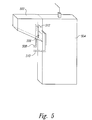
- FIG. 5 illustrates one embodiment of a fuel delivery mechanism.
- the present invention provides a means to determine the concentration of fuel within a fuel cell.
- a float is suspended in a methanol-water solution contained in the anode reservoir, or a float chamber in fluid communication with the anode reservoir, and is visible through a transparent window. Normal operation of the fuel cell lowers the concentration of methanol in the methanol-water solution within the anode reservoir. As the concentration of methanol decreases, the density of the methanol-water solution increases.
- the float having a density intermediate between the density of water and methanol, continuously rises from a lower position to a higher position as methanol is consumed and the density of the methanol-water solution increases. Thus, the position of the float corresponds to the concentration of methanol in the methanol-water solution.
- a fuel scale may be included to facilitate methanol concentration determination based on the float position in the methanol-water solution.
- FIG. 2A illustrates one embodiment of the present invention with a density-based fuel indicator in direct contact with the anode reservoir.
- the anode reservoir 202 includes a long, thin vertical window 204 visible from the exterior of the fuel cell.
- a fuel scale 206 affixed to the exterior of the fuel cell, extends along the vertical length of the window 204 .
- the fuel scale 206 is shown as a vertical line with a series of evenly spaced marks, each mark representing a fuel concentration.
- FIG. 2A shows a float 208 , suspended in fluid of a particular density, visible through a window 204 in the anode reservoir 202 .
- the float 208 utilizes a horizontal fuel indicator bar 210 to facilitate fuel concentration determination.
- the position of the fuel indicator bar 210 corresponds to a percentage of available fuel remaining.
- the position of the float 208 corresponds to a methanol concentration at which 87% of the available fuel supply remains.
- FIG. 2A shows a float chamber in fluid contact with the anode reservoir.
- a float chamber in fluid contact with the anode reservoir may contain the float.
- FIG. 2B shows a float chamber 212 separated from the anode reservoir 202 by a semi-permeable membrane 214 .
- the float 208 position corresponds to a methanol concentration at which 25% of the available fuel supply remains.
- FIG. 2C a float chamber is separated from the anode reservoir by a fuel channel.
- the fuel channel 216 may have variable lengths and shapes, but must have a cross sectional area large enough to allow for equilibration of the methanol concentration in the float chamber 212 within a reasonable time frame. Note that the position of the float 208 corresponds to a methanol concentration at which 40% of the available fuel supply remains.
- the fuel indicator system of the present invention determines the methanol concentration in a methanol-water solution by using the differences in densities between methanol-water solutions having high methanol concentrations and methanol-water solutions having low methanol concentrations.
- FIGS. 3 A-B show the effect of fluid density on float position.
- the density of pure water is 1.0000 kg/m 3
- the density of pure methanol is 0.7931 kg/m 3 at 20° C. and atmospheric pressure of 1.00 atm.
- the density of the methanol-water solution increases in relation to the decreasing concentration of methanol in the solution and the corresponding increase in concentration of water in the solution. For instance, at 0.5% methanol in water, the density is 0.9991 kg/m 3 at 20° C.
- FIG. 3A shows two different types of fuel scales.
- the fuel scale on the left 302 is an absolute scale that shows methanol concentrations in a methanol-water solution ranging from pure methanol to pure water.
- the fuel scale on the right 304 is a scale showing the available fuel remaining.
- the fuel scale on the right 304 is shorter than the fuel scale on the left 302 because the fuel scale on the right 304 encompasses a smaller range of fuel concentrations.
- Methanol fuel cells operate using methanol in a methanol-water solution.
- a fully-charged fuel cell of this embodiment contains a methanol-water fuel solution having a methanol concentration less that 100%, and a depleted fuel cell of this embodiment may contain a methanol-water solution having a methanol concentration greater than 0%.
- FIG. 3B shows a float in a charged methanol-water solution.
- the methanol-water solution has a high methanol concentration and a relatively low density.
- the float 306 sinks to the lower edge of the window 308 and the fuel indicator bar 310 corresponds to a value of 100% on the fuel scale 312 .
- FIG. 3C shows a float in a depleted methanol-water solution.
- the methanol-water solution has a low methanol concentration and a relatively high density.
- the float 314 rises to the upper edge of the window 316 and the fuel indicator bar 318 corresponds to a value of 0% on the fuel scale 320 .
- FIGS. 4 A-B and 5 illustrate an embodiment of the present invention with the float controlling the release of methanol into the anode reservoir.
- FIGS. 4 A-B show a float chamber 402 , incorporating a density-based fuel indicator system, separated from the anode reservoir by a fuel channel 404 and a semi-permeable filter membrane 406 .
- the float chamber 402 contains a photodiode 408 and a light emitting diode (“LED”) 410 .
- the LED 410 shines light 412 upon the photodiode 408 through the methanol-water solution in the float chamber 402 .
- FIG. 4A shows the float 414 in the lower portion of the float chamber 402 , indicating a relatively high concentration of methanol.
- the light 412 from the LED 410 reaches the photodiode 408 and the photodiode 408 remains deactivated.
- the float 414 rises within the methanol-water solution as methanol is consumed during operation of the fuel cell.
- FIG. 4B shows the float 414 in the upper portion of the float chamber 402 , indicating a relatively low concentration of the methanol.
- the float rises high enough to block light 412 , produced by the LED 410 , from reaching the photodiode 408 , thus activating the photodiode 408 .
- the photodiode 408 produces an electric current that triggers a mechanism to release fuel into the anode reservoir.
- the light 412 produced by the LED 410 activates the photodiode 408 .
- the float 414 rises during operation of the fuel cell, the float 414 ceases to block light 412 , produced by the LED 410 , from reaching the photodiode 408 , thus activating the photodiode 408 . Consequently, the photodiode 408 produces an electric current that triggers a mechanism to release fuel into the anode reservoir.
- FIG. 4 omits the window for clarity of illustration.
- FIG. 4 shows the float chamber 402 as a different shape than in previous illustrations, for clarity of illustration.
- Alternative embodiments employ the photodiode 408 and LED 410 within the anode reservoir.
- One embodiment of the fuel release mechanism shown in FIG. 5, comprises a fuel reservoir 502 separated from the anode reservoir 504 by a door 506 .
- the fuel reservoir contains nearly pure methanol without excess water added.
- Two wires 508 , 510 extending from the photodiode, 408 in FIG. 4, are in contact with a valve 512 that controls the aperture of the door 506 .
- the float rises enough to block the light from reaching the photodiode, thus activating the photodiode.
- An electric circuit is completed that signals the valve 512 to open the door 506 .
- Gravity allows the methanol in the fuel reservoir 502 to be released into the anode reservoir 504 .
- the float rises enough to cease blocking the light from reaching the photodiode, thus activating the photodiode.
- An electric circuit is completed that signals the valve 512 to open the door 506 .
- Gravity allows the methanol in the fuel reservoir 502 to be released into the anode reservoir 504 .
- a density-based float can be used with many hydrogen-rich liquid or gaseous fuels.
- Many different types of fuel-release systems are possible.
- the float can be in contact with different mechanical or electrical control valves or triggers used to actively or passively control the feeding of fuel into the anode reservoir.
- Fuel release can also be set to occur at any predetermined fuel concentration.
- Various different shapes, colors, sizes, orientations and positions of the window, float, and fuel scale may be used.
- the fuel scale may lie beside a rhomboidal window, or wrap around an oblong window.
- the anode reservoir or float chamber may be made entirely from a transparent material and lack a fuel scale.
Abstract
Description
- The present invention relates to fuel cells, and, in particular, to a density-based fuel indicator system for use with fuel cells.
- Fuel cells produce electrical energy by reacting a fuel with an oxidant, usually in the presence of a catalyst. Typically, fuel cells consist of a fuel electrode, or anode, and a reducing electrode, or cathode, separated by an ion-conducting electrolyte. An external conductor connects the electrodes to an electrical circuit, or load. In the conductor, current is transported by the flow of electrons. In the electrolyte, current is transported by the flow of ions.
- Any number of hydrogen rich fuels may be used as a fuel source, such as methanol, ethanol, butane, and propane. FIG. 1 is a diagram of a methanol fuel cell. A reservoir that includes the anode, or
anode reservoir 102, contains a methanol-water solution 104. The methanol fuel cell generally is in a charged state when the percentage of methanol in the methanol-water solution is relatively large. As methanol is oxidized and electricity is generated by the fuel cell, the percentage of methanol in the methanol-water solution decreases and the fuel cell becomes depleted. - The methanol contained within the methanol-water solution is oxidized, usually in the presence of a catalyst, producing
hydrogen ions 106,electrons 108, andcarbon dioxide 116. This oxidation reaction occurs inside theanode reservoir 102 of the fuel cell. A primary anode oxidation reaction is shown below: - CH3OH+H2O→CO2+6H++6e −
- Note that, since the electrolyte is a relatively poor electrical conductor,
electrons 108 flow away from the anode via anexternal circuit 110. Simultaneously,hydrogen ions 106 travel through the electrolyte, ormembrane 112, to thecathode 114. Commonly used membranes include Nafion 112®, Nafion 117®, and polybenzimidazole. - At the
cathode 114 of a fuel cell,oxygen 118 is reduced byhydrogen ions 106 migrating through theelectrolyte 112 and incomingelectrons 108 from theexternal circuit 110 to producewater 120. The primary cathode reaction is shown below: - 3/2O2+6H++6e −→3H2O
- The individual electrode reactions, described above as primary anode and primary cathode reactions, result in an overall methanol-fuel-cell reaction shown below:
- 2CH3OH+3O2→2CO2+4H2O+electricity
- Additional minor chemical reactions may occur, and thermal energy is generally produced.
- Modern fuel cells can continuously produce electrical current for long periods of time without the need for recharging. However, fuel cells produce electrical charge only when fuel is present in the anode reservoir above a threshold concentration. Therefore, in order to ensure continuous operation of a fuel cell, an indication of the amount of fuel remaining in the fuel cell needs to be easily obtainable. Fuel cells commonly provide no convenient, cost-efficient means for reliably determining the amount of available fuel remaining in the fuel cell. Therefore, designers, manufacturers, and users of fuel cells have recognized the need for a convenient, cost-efficient means for determining the amount of fuel remaining in a fuel cell.
- One embodiment of the present invention provides a means for determining the concentration of methanol within an anode reservoir of a methanol-based fuel cell. The methanol concentration is determined through the use of a float that responds to the density of the methanol-water solution. As methanol is consumed during normal operation of the fuel cell, the methanol concentration of the methanol-water solution decreases and the density of the methanol-water solution correspondingly increases. The float is fabricated to have a density such that, as methanol is consumed, the float rises from a lower position within the anode reservoir, or within a float chamber in fluid communication with the anode reservoir, to a higher position in the anode reservoir or float chamber. A fuel scale may be included with the fuel cell to facilitate determination of the methanol concentration by visual comparison of the float position with markings on the fuel scale corresponding to fuel concentrations. Additionally, a valve responsive to the position of the float may act to control fuel delivery. Alternative embodiments may employ different types of hydrogen-rich fuels.
- FIG. 1 is a diagram of a methanol fuel cell.
- FIG. 2A shows a density-based fuel indicator in direct contact with the anode reservoir.
- FIG. 2B shows a float chamber with a density-based fuel indicator separated from the anode reservoir by a membrane.
- FIG. 2C shows a float chamber with a density-based fuel indicator separated from the anode reservoir by a fuel channel and an optional membrane.
- FIG. 3A shows the relationship between an absolute fuel scale and an available-fuel-remaining fuel scale.
- FIGS. 3B-C show the effect of fluid density on float position.
- FIGS. 4A-B illustrate an embodiment of the present invention with the fuel delivery controlled by the float.
- FIG. 5 illustrates one embodiment of a fuel delivery mechanism.
- The present invention provides a means to determine the concentration of fuel within a fuel cell. In one embodiment, a float is suspended in a methanol-water solution contained in the anode reservoir, or a float chamber in fluid communication with the anode reservoir, and is visible through a transparent window. Normal operation of the fuel cell lowers the concentration of methanol in the methanol-water solution within the anode reservoir. As the concentration of methanol decreases, the density of the methanol-water solution increases. The float, having a density intermediate between the density of water and methanol, continuously rises from a lower position to a higher position as methanol is consumed and the density of the methanol-water solution increases. Thus, the position of the float corresponds to the concentration of methanol in the methanol-water solution. A fuel scale may be included to facilitate methanol concentration determination based on the float position in the methanol-water solution.
- FIG. 2A illustrates one embodiment of the present invention with a density-based fuel indicator in direct contact with the anode reservoir. The
anode reservoir 202 includes a long, thinvertical window 204 visible from the exterior of the fuel cell. Afuel scale 206, affixed to the exterior of the fuel cell, extends along the vertical length of thewindow 204. Thefuel scale 206 is shown as a vertical line with a series of evenly spaced marks, each mark representing a fuel concentration. - FIG. 2A shows a
float 208, suspended in fluid of a particular density, visible through awindow 204 in theanode reservoir 202. Thefloat 208 utilizes a horizontalfuel indicator bar 210 to facilitate fuel concentration determination. The position of thefuel indicator bar 210 corresponds to a percentage of available fuel remaining. In FIG. 2A, the position of thefloat 208 corresponds to a methanol concentration at which 87% of the available fuel supply remains. - In the above-described embodiment, shown in FIG. 2A, the float is contained directly inside the anode reservoir. In alterative embodiments, a float chamber in fluid contact with the anode reservoir may contain the float. FIG. 2B shows a
float chamber 212 separated from theanode reservoir 202 by asemi-permeable membrane 214. In FIG. 2B, thefloat 208 position corresponds to a methanol concentration at which 25% of the available fuel supply remains. In FIG. 2C, a float chamber is separated from the anode reservoir by a fuel channel. Thefuel channel 216 may have variable lengths and shapes, but must have a cross sectional area large enough to allow for equilibration of the methanol concentration in thefloat chamber 212 within a reasonable time frame. Note that the position of thefloat 208 corresponds to a methanol concentration at which 40% of the available fuel supply remains. - Suspension of the
float 208 within the methanol-water solution requires thefloat 208 to have a density intermediate to the density of pure methanol and the density of pure water. Thefloat 208 is often attached to a long cylinder, whose depth within the methanol-water solution depends on the density of the methanol-water solution. The movement of thefloat 208 within the methanol-water solution follows Archimedes' principle, according to which the buoyant force on a body immersed in a fluid is equal to the weight of the fluid displaced by that object. Therefore, provided the weight and volume of a float immersed in a fluid remains constant, the float rises as the fluid surrounding the float becomes more dense. - The fuel indicator system of the present invention determines the methanol concentration in a methanol-water solution by using the differences in densities between methanol-water solutions having high methanol concentrations and methanol-water solutions having low methanol concentrations. FIGS. 3A-B show the effect of fluid density on float position. The density of pure water is 1.0000 kg/m3, and the density of pure methanol is 0.7931 kg/m3 at 20° C. and atmospheric pressure of 1.00 atm. As methanol is consumed during operation of the fuel cell, the density of the methanol-water solution increases in relation to the decreasing concentration of methanol in the solution and the corresponding increase in concentration of water in the solution. For instance, at 0.5% methanol in water, the density is 0.9991 kg/m3 at 20° C.
- FIG. 3A shows two different types of fuel scales. The fuel scale on the left 302 is an absolute scale that shows methanol concentrations in a methanol-water solution ranging from pure methanol to pure water. The fuel scale on the right 304 is a scale showing the available fuel remaining. The fuel scale on the right 304 is shorter than the fuel scale on the left 302 because the fuel scale on the right 304 encompasses a smaller range of fuel concentrations. Methanol fuel cells operate using methanol in a methanol-water solution. Consequently, a fully-charged fuel cell of this embodiment contains a methanol-water fuel solution having a methanol concentration less that 100%, and a depleted fuel cell of this embodiment may contain a methanol-water solution having a methanol concentration greater than 0%.
- FIG. 3B shows a float in a charged methanol-water solution. The methanol-water solution has a high methanol concentration and a relatively low density. In a solution of relatively low density, the
float 306 sinks to the lower edge of thewindow 308 and thefuel indicator bar 310 corresponds to a value of 100% on thefuel scale 312. FIG. 3C shows a float in a depleted methanol-water solution. The methanol-water solution has a low methanol concentration and a relatively high density. In a solution of relatively high density, thefloat 314 rises to the upper edge of thewindow 316 and thefuel indicator bar 318 corresponds to a value of 0% on thefuel scale 320. - FIGS. 4A-B and 5 illustrate an embodiment of the present invention with the float controlling the release of methanol into the anode reservoir. FIGS. 4A-B show a
float chamber 402, incorporating a density-based fuel indicator system, separated from the anode reservoir by afuel channel 404 and asemi-permeable filter membrane 406. Thefloat chamber 402 contains aphotodiode 408 and a light emitting diode (“LED”) 410. TheLED 410 shines light 412 upon thephotodiode 408 through the methanol-water solution in thefloat chamber 402. FIG. 4A shows thefloat 414 in the lower portion of thefloat chamber 402, indicating a relatively high concentration of methanol. The light 412 from theLED 410 reaches thephotodiode 408 and thephotodiode 408 remains deactivated. Thefloat 414 rises within the methanol-water solution as methanol is consumed during operation of the fuel cell. FIG. 4B shows thefloat 414 in the upper portion of thefloat chamber 402, indicating a relatively low concentration of the methanol. At a predetermined methanol level, the float rises high enough to block light 412, produced by theLED 410, from reaching thephotodiode 408, thus activating thephotodiode 408. Thephotodiode 408 produces an electric current that triggers a mechanism to release fuel into the anode reservoir. - Alternately, at a predetermined methanol level, the light 412 produced by the
LED 410 activates thephotodiode 408. As thefloat 414 rises during operation of the fuel cell, thefloat 414 ceases to block light 412, produced by theLED 410, from reaching thephotodiode 408, thus activating thephotodiode 408. Consequently, thephotodiode 408 produces an electric current that triggers a mechanism to release fuel into the anode reservoir. Note that FIG. 4 omits the window for clarity of illustration. Note also that FIG. 4 shows thefloat chamber 402 as a different shape than in previous illustrations, for clarity of illustration. Alternative embodiments employ thephotodiode 408 andLED 410 within the anode reservoir. - One embodiment of the fuel release mechanism, shown in FIG. 5, comprises a
fuel reservoir 502 separated from theanode reservoir 504 by adoor 506. The fuel reservoir contains nearly pure methanol without excess water added. Twowires valve 512 that controls the aperture of thedoor 506. At a predetermined methanol level, the float rises enough to block the light from reaching the photodiode, thus activating the photodiode. An electric circuit is completed that signals thevalve 512 to open thedoor 506. Gravity allows the methanol in thefuel reservoir 502 to be released into theanode reservoir 504. Alternatively, at a predetermined methanol level, the float rises enough to cease blocking the light from reaching the photodiode, thus activating the photodiode. An electric circuit is completed that signals thevalve 512 to open thedoor 506. Gravity allows the methanol in thefuel reservoir 502 to be released into theanode reservoir 504. - Although the present invention has been described in terms of a particular embodiment, it is not intended that the invention be limited to this embodiment. Modifications within the spirit of the invention will be apparent to those skilled in the art. For example, as discussed above, a density-based float can be used with many hydrogen-rich liquid or gaseous fuels. Many different types of fuel-release systems are possible. The float can be in contact with different mechanical or electrical control valves or triggers used to actively or passively control the feeding of fuel into the anode reservoir. Fuel release can also be set to occur at any predetermined fuel concentration. Various different shapes, colors, sizes, orientations and positions of the window, float, and fuel scale may be used. For instance, the fuel scale may lie beside a rhomboidal window, or wrap around an oblong window. Alternatively, the anode reservoir or float chamber may be made entirely from a transparent material and lack a fuel scale.
- The foregoing description, for purposes of explanation used specific nomenclature to provide a thorough understanding of the invention. However, it will be apparent to one skilled in the art that the specific details are not required in order to practice the invention. In other instances, well-known portions of fuel cells are shown as diagrams in order to avoid unnecessary distraction from the underlying invention. Thus, the foregoing descriptions of specific embodiments of the present invention are presented for purposes of illustration and description. They are not intended to be exhaustive or to limit the invention to the precise forms disclosed. Obviously many modifications and variations are possible in view of the above teachings. The embodiments are shown and described in order to best enable others skilled in the art to best utilize the invention and various embodiments with various modifications as are suited to the particular use contemplated. It is intended that the scope of the invention be defined by the following claims and their equivalents:
Claims (16)
Priority Applications (1)
| Application Number | Priority Date | Filing Date | Title |
|---|---|---|---|
| US10/044,088 US6789421B2 (en) | 2002-01-11 | 2002-01-11 | Density-based fuel indicator system for fuel cells |
Applications Claiming Priority (1)
| Application Number | Priority Date | Filing Date | Title |
|---|---|---|---|
| US10/044,088 US6789421B2 (en) | 2002-01-11 | 2002-01-11 | Density-based fuel indicator system for fuel cells |
Publications (2)
| Publication Number | Publication Date |
|---|---|
| US20030131663A1 true US20030131663A1 (en) | 2003-07-17 |
| US6789421B2 US6789421B2 (en) | 2004-09-14 |
Family
ID=21930463
Family Applications (1)
| Application Number | Title | Priority Date | Filing Date |
|---|---|---|---|
| US10/044,088 Expired - Lifetime US6789421B2 (en) | 2002-01-11 | 2002-01-11 | Density-based fuel indicator system for fuel cells |
Country Status (1)
| Country | Link |
|---|---|
| US (1) | US6789421B2 (en) |
Cited By (10)
| Publication number | Priority date | Publication date | Assignee | Title |
|---|---|---|---|---|
| US20050118468A1 (en) * | 2003-12-01 | 2005-06-02 | Paul Adams | Fuel cell supply including information storage device and control system |
| US20050115312A1 (en) * | 2003-12-01 | 2005-06-02 | Curello Andrew J. | Fuel gauge for fuel cartridges |
| US20050255359A1 (en) * | 2004-05-11 | 2005-11-17 | Paul Adams | Cartridge with fuel supply and membrane electrode assembly stack |
| US20060014069A1 (en) * | 2003-06-27 | 2006-01-19 | Ultracell Corporation | Smart fuel cell cartridge |
| US20060019135A1 (en) * | 2003-12-01 | 2006-01-26 | Curello Andrew J | Fuel cell with fuel monitoring system and method of use |
| US20060127711A1 (en) * | 2004-06-25 | 2006-06-15 | Ultracell Corporation, A California Corporation | Systems and methods for fuel cartridge distribution |
| US20090007705A1 (en) * | 2006-12-22 | 2009-01-08 | Mclean Gerard F | Sensing device and methods related thereto |
| US7648792B2 (en) | 2004-06-25 | 2010-01-19 | Ultracell Corporation | Disposable component on a fuel cartridge and for use with a portable fuel cell system |
| US7968250B2 (en) | 2004-06-25 | 2011-06-28 | Ultracell Corporation | Fuel cartridge connectivity |
| US11233249B1 (en) * | 2017-02-24 | 2022-01-25 | Tennessee Technological University | Advanced selectively gas permeable anode flow field design for efficient removal of carbon dioxide in a direct formic acid fuel cell |
Families Citing this family (8)
| Publication number | Priority date | Publication date | Assignee | Title |
|---|---|---|---|---|
| DE10319646B3 (en) * | 2003-05-02 | 2004-09-02 | Hilti Ag | Drive medium container for setting device, has data memory identification unit on the container in which drive medium level data can be stored and from which the data can be read out |
| KR20070055517A (en) * | 2004-07-27 | 2007-05-30 | 후마킬라 가부시키가이샤 | Fan-assisted medicine diffuser employing fuel cell as power supply |
| US20060204802A1 (en) * | 2005-03-10 | 2006-09-14 | Specht Steven J | Fuel cell systems and related methods |
| US7198834B2 (en) * | 2005-03-22 | 2007-04-03 | Hewlett-Packard Development Company, L.P. | Imaging media including interference layer for generating human-readable marking on optical media |
| US20080223130A1 (en) * | 2007-03-13 | 2008-09-18 | Provina Incorporated | Method and device for measuring density of a liquid |
| CN101644651B (en) * | 2009-07-17 | 2011-07-20 | 郑州轻工业学院 | Device for automatically detecting and supplementing concentration of methanol solution in direct methanol fuel cells |
| US10169906B2 (en) | 2013-03-29 | 2019-01-01 | Advanced Micro Devices, Inc. | Hybrid render with deferred primitive batch binning |
| AU2016389247B2 (en) * | 2016-01-27 | 2019-06-13 | Micro Motion, Inc. | Gas energy measurement method and related apparatus |
Citations (8)
| Publication number | Priority date | Publication date | Assignee | Title |
|---|---|---|---|---|
| US4443424A (en) * | 1982-09-30 | 1984-04-17 | Shell Oil Company | Method of removing hydrogen sulfide from gases utilizing a polyvalent metal chelate solution and electrolytically regenerating the solution |
| US4496637A (en) * | 1982-12-27 | 1985-01-29 | Toyo Boseki Kabushiki Kaisha | Electrode for flowcell |
| US4650729A (en) * | 1984-08-10 | 1987-03-17 | Nissan Motor Co., Ltd. | Electric power source device |
| US4700580A (en) * | 1986-02-24 | 1987-10-20 | Kamin Paul N | Aviation fuel tester |
| US4967595A (en) * | 1989-04-24 | 1990-11-06 | Roger Olson | Aviation fuel sample tester |
| US5518831A (en) * | 1995-07-07 | 1996-05-21 | The Dow Chemical Company | Electrocatalytic structure |
| US5534363A (en) * | 1994-03-22 | 1996-07-09 | Rockwell International Corporation | Hollow artery anode wick for passive variable pressure regenerative fuel cells |
| US6506513B1 (en) * | 1999-09-21 | 2003-01-14 | Kabushiki Kaisha Toshiba | Liquid fuel-housing tank for fuel cell and fuel cell |
Family Cites Families (9)
| Publication number | Priority date | Publication date | Assignee | Title |
|---|---|---|---|---|
| JPS5431708B1 (en) * | 1971-07-30 | 1979-10-09 | ||
| DE2150477A1 (en) * | 1971-10-09 | 1973-04-12 | Daimler Benz Ag | WARNING DEVICE FOR INDICATING A CRITICAL CHARGE STATE OF THE STARTER BATTERIES IN VEHICLES. |
| US3952761A (en) * | 1974-03-25 | 1976-04-27 | Donald Friedland | System for controlling density of liquids |
| US4353253A (en) * | 1980-05-02 | 1982-10-12 | Callahan George E | Device for measuring the density of fluids |
| US4400978A (en) * | 1981-09-01 | 1983-08-30 | Louis Boivin | Electronic hydrometer and method of determining the density of a liquid |
| US4442700A (en) * | 1982-03-09 | 1984-04-17 | The United States Of America As Represented By The United States Department Of Energy | Ultrasonic hydrometer |
| JPH0237881A (en) * | 1988-07-28 | 1990-02-07 | Canon Inc | Photoelectric converter |
| SE504256C2 (en) * | 1995-02-14 | 1996-12-16 | Siemens Elema Ab | Device intended for use in anesthesia equipment to identify anesthetic agents |
| US6408694B1 (en) * | 1999-11-29 | 2002-06-25 | Taiwan Semiconductor Manufacturing Company, Ltd. | Apparatus and method for on-line monitoring of a liquid density |
-
2002
- 2002-01-11 US US10/044,088 patent/US6789421B2/en not_active Expired - Lifetime
Patent Citations (8)
| Publication number | Priority date | Publication date | Assignee | Title |
|---|---|---|---|---|
| US4443424A (en) * | 1982-09-30 | 1984-04-17 | Shell Oil Company | Method of removing hydrogen sulfide from gases utilizing a polyvalent metal chelate solution and electrolytically regenerating the solution |
| US4496637A (en) * | 1982-12-27 | 1985-01-29 | Toyo Boseki Kabushiki Kaisha | Electrode for flowcell |
| US4650729A (en) * | 1984-08-10 | 1987-03-17 | Nissan Motor Co., Ltd. | Electric power source device |
| US4700580A (en) * | 1986-02-24 | 1987-10-20 | Kamin Paul N | Aviation fuel tester |
| US4967595A (en) * | 1989-04-24 | 1990-11-06 | Roger Olson | Aviation fuel sample tester |
| US5534363A (en) * | 1994-03-22 | 1996-07-09 | Rockwell International Corporation | Hollow artery anode wick for passive variable pressure regenerative fuel cells |
| US5518831A (en) * | 1995-07-07 | 1996-05-21 | The Dow Chemical Company | Electrocatalytic structure |
| US6506513B1 (en) * | 1999-09-21 | 2003-01-14 | Kabushiki Kaisha Toshiba | Liquid fuel-housing tank for fuel cell and fuel cell |
Cited By (26)
| Publication number | Priority date | Publication date | Assignee | Title |
|---|---|---|---|---|
| US20060014069A1 (en) * | 2003-06-27 | 2006-01-19 | Ultracell Corporation | Smart fuel cell cartridge |
| US7291191B2 (en) | 2003-06-27 | 2007-11-06 | Ultracell Corporation | Fuel cell cartridge filters and pressure relief |
| US20060070891A1 (en) * | 2003-06-27 | 2006-04-06 | Ultracell Corporation | Fuel cell cartridge filters and pressure relief |
| US20060024553A1 (en) * | 2003-06-27 | 2006-02-02 | Ultracell Corporation | Hot swappable fuel cell system |
| US20060019135A1 (en) * | 2003-12-01 | 2006-01-26 | Curello Andrew J | Fuel cell with fuel monitoring system and method of use |
| US7642742B2 (en) | 2003-12-01 | 2010-01-05 | Societe Bic | Fuel cell system with fuel supply monitoring system and method of use |
| US20050118468A1 (en) * | 2003-12-01 | 2005-06-02 | Paul Adams | Fuel cell supply including information storage device and control system |
| WO2005055340A2 (en) | 2003-12-01 | 2005-06-16 | Societe Bic | Fuel gauge for fuel cartridges |
| WO2005055337A2 (en) | 2003-12-01 | 2005-06-16 | Societe Bic | Fuel cell supply including information storage device and control system |
| US10090547B2 (en) | 2003-12-01 | 2018-10-02 | Intelligent Energy Limited | Fuel cell supply including information storage device and control system |
| US7117732B2 (en) | 2003-12-01 | 2006-10-10 | Societe Bic | Fuel gauge for fuel cartridges |
| EP2426764A2 (en) | 2003-12-01 | 2012-03-07 | Société BIC | Fuel cell supply including information storage device and control system |
| US20050115312A1 (en) * | 2003-12-01 | 2005-06-02 | Curello Andrew J. | Fuel gauge for fuel cartridges |
| EP2424023A2 (en) | 2003-12-01 | 2012-02-29 | Société BIC | Fuel gauge for fuel cartridges |
| US7655331B2 (en) | 2003-12-01 | 2010-02-02 | Societe Bic | Fuel cell supply including information storage device and control system |
| US20050255359A1 (en) * | 2004-05-11 | 2005-11-17 | Paul Adams | Cartridge with fuel supply and membrane electrode assembly stack |
| EP2400587A1 (en) | 2004-05-11 | 2011-12-28 | Société BIC | Cartridge with fuel supply and membrane electrode assembly stack |
| US7217470B2 (en) | 2004-05-11 | 2007-05-15 | Societe Bic | Cartridge with fuel supply and membrane electrode assembly stack |
| US7648792B2 (en) | 2004-06-25 | 2010-01-19 | Ultracell Corporation | Disposable component on a fuel cartridge and for use with a portable fuel cell system |
| US7968250B2 (en) | 2004-06-25 | 2011-06-28 | Ultracell Corporation | Fuel cartridge connectivity |
| US20060127711A1 (en) * | 2004-06-25 | 2006-06-15 | Ultracell Corporation, A California Corporation | Systems and methods for fuel cartridge distribution |
| US20080231836A1 (en) * | 2005-08-02 | 2008-09-25 | Societe Bic | Fuel Cell with Fuel Monitoring System and Method of Use |
| US20090007705A1 (en) * | 2006-12-22 | 2009-01-08 | Mclean Gerard F | Sensing device and methods related thereto |
| US8286464B2 (en) | 2006-12-22 | 2012-10-16 | Societe Bic | Sensing device and methods related thereto |
| US11233249B1 (en) * | 2017-02-24 | 2022-01-25 | Tennessee Technological University | Advanced selectively gas permeable anode flow field design for efficient removal of carbon dioxide in a direct formic acid fuel cell |
| US11728493B1 (en) * | 2017-02-24 | 2023-08-15 | Tennessee Technological University | Advanced selectively gas permeable anode flow field design for efficient removal of carbon dioxide in a fuel cell |
Also Published As
| Publication number | Publication date |
|---|---|
| US6789421B2 (en) | 2004-09-14 |
Similar Documents
| Publication | Publication Date | Title |
|---|---|---|
| US6789421B2 (en) | Density-based fuel indicator system for fuel cells | |
| US6998185B2 (en) | Dye-based fuel indicator system for fuel cells | |
| US6666963B1 (en) | Oxygen sensor | |
| KR20040021651A (en) | Method for controlling the methanol concentration in direct methanol fuel cells | |
| JP2007514281A (en) | Fuel cell system having an ion filter | |
| US20090029203A1 (en) | Fuel Cell System With an Electrochemical Hydrogen Generation Cell | |
| CN105829581A (en) | Device and method for the flexible use of electricity | |
| WO2004046408B1 (en) | Electrochemical reformer and fuel cell system | |
| CN101015078A (en) | Extended catalyzed layer for minimizing cross-over oxygen and consuming peroxide | |
| US20090087706A1 (en) | Fuel cell power generation system | |
| CN100544085C (en) | Liner that can measuring voltage and have the fuel cell system of this liner | |
| KR100739303B1 (en) | Fuel supply system for fuel cell and fuel cell system using the same | |
| JP4867345B2 (en) | Fuel cartridge for fuel cell and fuel cell having the same | |
| JP2006059624A (en) | Circulation type liquid fuel cell | |
| US20100233566A1 (en) | Fuel cell and fuel cell system | |
| US20070274872A1 (en) | Reactant delivery system and reactor | |
| US7255950B2 (en) | Fuel delivery system and method of use thereof | |
| US8637199B2 (en) | Fuel cell using organic fuel | |
| KR100519767B1 (en) | Fuel amount control system comprising pressure sensor | |
| JP2008274391A (en) | Hydrogen generating apparatus and fuel cell system using the same | |
| KR100675690B1 (en) | Methanol supply apparatus for fuel cell | |
| KR100689332B1 (en) | Methanol supply apparatus for fuel cell and method thereof | |
| KR100625693B1 (en) | Methanol supply apparatus for fuel cell | |
| US20100282599A1 (en) | Method for manufacturing of hydrogen generating apparatus and hydrogen generating apparatus using the same | |
| JP2007234576A (en) | Direct formic acid fuel cell and its operation method |
Legal Events
| Date | Code | Title | Description |
|---|---|---|---|
| AS | Assignment |
Owner name: HEWLETT-PACKARD COMPANY, COLORADO Free format text: ASSIGNMENT OF ASSIGNORS INTEREST;ASSIGNORS:GORE, MAKARAND P.;MANN, L. CHRIS;REEL/FRAME:013759/0368;SIGNING DATES FROM 20020102 TO 20020108 |
|
| AS | Assignment |
Owner name: HEWLETT-PACKARD DEVELOPMENT COMPANY L.P., TEXAS Free format text: ASSIGNMENT OF ASSIGNORS INTEREST;ASSIGNOR:HEWLETT-PACKARD COMPANY;REEL/FRAME:014061/0492 Effective date: 20030926 Owner name: HEWLETT-PACKARD DEVELOPMENT COMPANY L.P.,TEXAS Free format text: ASSIGNMENT OF ASSIGNORS INTEREST;ASSIGNOR:HEWLETT-PACKARD COMPANY;REEL/FRAME:014061/0492 Effective date: 20030926 |
|
| STCF | Information on status: patent grant |
Free format text: PATENTED CASE |
|
| FPAY | Fee payment |
Year of fee payment: 4 |
|
| REMI | Maintenance fee reminder mailed | ||
| AS | Assignment |
Owner name: EVEREADY BATTERY COMPANY, INC., MISSOURI Free format text: ASSIGNMENT OF ASSIGNORS INTEREST;ASSIGNORS:HEWLETT-PACKARD DEVELOPMENT COMPANY, L.P.;HEWLETT-PACKARD COMPANY;REEL/FRAME:026463/0542 Effective date: 20101029 |
|
| FPAY | Fee payment |
Year of fee payment: 8 |
|
| AS | Assignment |
Owner name: INTELLIGENT ENERGY LIMITED, UNITED KINGDOM Free format text: ASSIGNMENT OF ASSIGNORS INTEREST;ASSIGNOR:EVEREADY BATTERY COMPANY, INC.;REEL/FRAME:032124/0514 Effective date: 20131219 |
|
| FPAY | Fee payment |
Year of fee payment: 12 |