US20030097388A1 - Cordic method and architecture applied in vector rotation - Google Patents
Cordic method and architecture applied in vector rotation Download PDFInfo
- Publication number
- US20030097388A1 US20030097388A1 US10/138,652 US13865202A US2003097388A1 US 20030097388 A1 US20030097388 A1 US 20030097388A1 US 13865202 A US13865202 A US 13865202A US 2003097388 A1 US2003097388 A1 US 2003097388A1
- Authority
- US
- United States
- Prior art keywords
- cordic
- micro
- elementary
- register
- output terminal
- Prior art date
- Legal status (The legal status is an assumption and is not a legal conclusion. Google has not performed a legal analysis and makes no representation as to the accuracy of the status listed.)
- Granted
Links
- 238000000034 method Methods 0.000 title claims abstract description 36
- 230000001186 cumulative effect Effects 0.000 claims description 7
- 238000009825 accumulation Methods 0.000 description 2
- 238000009795 derivation Methods 0.000 description 2
- 238000012545 processing Methods 0.000 description 2
- 238000012546 transfer Methods 0.000 description 2
- 238000012937 correction Methods 0.000 description 1
- 238000001914 filtration Methods 0.000 description 1
- 239000011159 matrix material Substances 0.000 description 1
- 238000012986 modification Methods 0.000 description 1
- 230000004048 modification Effects 0.000 description 1
- 238000013341 scale-up Methods 0.000 description 1
- 230000009466 transformation Effects 0.000 description 1
- 238000000844 transformation Methods 0.000 description 1
Images

Classifications
-
- G—PHYSICS
- G06—COMPUTING; CALCULATING OR COUNTING
- G06F—ELECTRIC DIGITAL DATA PROCESSING
- G06F7/00—Methods or arrangements for processing data by operating upon the order or content of the data handled
- G06F7/38—Methods or arrangements for performing computations using exclusively denominational number representation, e.g. using binary, ternary, decimal representation
- G06F7/48—Methods or arrangements for performing computations using exclusively denominational number representation, e.g. using binary, ternary, decimal representation using non-contact-making devices, e.g. tube, solid state device; using unspecified devices
- G06F7/544—Methods or arrangements for performing computations using exclusively denominational number representation, e.g. using binary, ternary, decimal representation using non-contact-making devices, e.g. tube, solid state device; using unspecified devices for evaluating functions by calculation
- G06F7/5446—Methods or arrangements for performing computations using exclusively denominational number representation, e.g. using binary, ternary, decimal representation using non-contact-making devices, e.g. tube, solid state device; using unspecified devices for evaluating functions by calculation using crossaddition algorithms, e.g. CORDIC
Definitions
- the present invention relates to a COordinate Rotational DIgital Computer (CORDIC) method and a CORDIC architecture applied in vector rotation, and more particularly, to a CORDIC method based on Extended Elementary-Angle Sets (EEAS) and Trellis-based Searching (TBS) and its architecture.
- CORDIC COordinate Rotational DIgital Computer
- EEAS Extended Elementary-Angle Sets
- TBS Trellis-based Searching
- vector rotation is the kernel of various digital signal-processing applications, including discrete orthogonal transformations, lattice-based digital filtering, matrix computation, complex-valued number manipulation, etc.
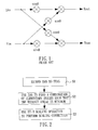
- FIG. 1 shows hardware architecture used to implement the vector rotation operation, which requires four adders and two multipliers. That is, the execution of one vector rotation operation will require executing four addition operations and two multiplication operations. The complexity of such an execution is too high. Reducing the wordlength can decrease the complexity. However, the SQNR will be increased accordingly.
- the CORDIC algorithm is a well-known iterative method for the computation of vector rotation, which requires only one shift operation and one addition operation to perform a vector rotation operation.
- N is the number of elementary angles
- ⁇ ⁇ 1
- ⁇ denotes the residue angle
- each elementary angle needs to be performed sequentially so as to complete the micro-rotation phase.
- the angle recoding (AR) technique is done by extending the set of ⁇ (i) from ⁇ 1, ⁇ 1 ⁇ to ⁇ 1, ⁇ 1, 0 ⁇ .
- Rotation angles of different values may need unequal numbers of iterations, which may lead to bus/timing alignment problems in VLSI circuits. Therefore, it is desired for the above CORDIC algorithm to be improved to mitigate and/or obviate the aforementioned problems.
- the object of the present invention is to provide a CORDIC method and a CORDIC architecture applied in vector rotation, which can effectively improve SQNR performance, reduce the number of iterations and decrease the hardware complexity.
- a CORDIC method applied in vector rotation is provided, which first extends an elementary angles set:
- s 2 ⁇ tan ⁇ 1 ( a′ 0 *2 ⁇ s′ 0 +a′ 1 *2 ⁇ s′ 1 ): a′ 0 ,a′ 1 ⁇ 1,0,1, ⁇ , s′ 0 ,s′ 1 ⁇ 0,1, . . . , N ⁇ 1 ⁇ ,
- N is the number of elementary angles.
- ⁇ m
- ⁇ - ⁇ j 0 R m - 1 ⁇ tan - 1 [ a 0 ⁇ ( j ) * 2 - S 0 ⁇ ( j ) + a 1 ⁇ ( j ) * 2 - S 1 ⁇ ( j )
- ⁇ m
- ⁇ - ⁇ j 0 R m - 1 ⁇ tan - 1 [ a 0 ⁇ ( j ) * 2 - S 0 ⁇ ( j ) + a 1 ⁇ ( j ) * 2 - S 1 ⁇ ( j )
- ⁇ m
- ⁇ j * 2 - S 0 ⁇ ( j ) + a 1 ⁇ ( j ) * 2 - S 1 ⁇ ( j )
- ⁇ is a target angle
- R m is the maximum iteration number
- j denotes the iteration index
- s 0 (j), s 1 (j) ⁇ 0, 1, . . . , N ⁇ 1 ⁇ are the rotational sequences
- a 0 (j), a 1 (j) control the direction of j-th micro-rotation of 2 ⁇ S 0 (j) , 2 ⁇ S 1 (j) .
- a quantized scaling factor is used to scale the combination of elementary angles determined in step (B) after being micro-rotated.
- a first register is provided for temporarily storing x(i) or ⁇ tilde over (x) ⁇ (m).
- a second register is provided for temporarily storing y(i) or ⁇ tilde over (y) ⁇ (m) .
- First and second barrel shifters have input terminals connected to output terminals of the first register.
- Third and fourth barrel shifters have input terminals connected to output terminals of the second register.
- a first multiplexer has a first input terminal connected to an output terminal of the first barrel shifter, and a second input terminal connected to an output terminal of the third barrel shifter.
- a second multiplexer has a first input terminal connected to an output terminal of the second barrel shifter, and a second input terminal connected to an output terminal of the fourth barrel shifter.
- a third multiplexer has a first input terminal connected to the output terminal of the first barrel shifter, and a second input terminal connected to an output terminal of the third barrel shifter.
- a fourth multiplexer has a first input terminal connected to the output terminal of the second barrel shifter, and a second input terminal connected to the output terminal of the fourth barrel shifter.
- a first adder/subtractor has two input terminals connected to output terminals of the first and second multiplexers, respectively.
- a second adder/subtractor has two input terminals connected to output terminals of the first adder/subtractor and first register, respectively, and an output terminal connected to an input terminal of the first register.
- a third adder/subtractor has two input terminals connected to output terminals of the third and fourth multiplexers, respectively.
- a fourth adder/subtractor has two input terminals connected to output terminals of the third adder/subtractor and second register, respectively, and an output terminal connected to an input terminal of the second register.
- a control unit controls the first to fourth barrel shifters, the first to fourth multiplexers, and the first to fourth adders/subtractors to perform the CORDIC operation iteratively.
- a CORDIC architecture applied in vector rotation having (R m +R s ) CORDIC processors connected in cascade form, in which the R m leading processors are used in the micro-rotation phase and the following R s processors are used in the scaling phase.
- FIG. 1 shows a conventional hardware architecture for implementing vector rotation
- FIG. 2 is the flowchart of the CORDIC method in accordance with the present invention.
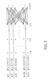
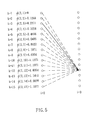
- FIG. 3 schematically illustrates the initialization and transfer path of the TBS algorithm
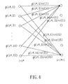
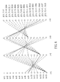
- FIG. 4 schematically illustrates an accumulation step example in the TBS algorithm
- FIG. 5 schematically illustrates a selection step example in the TBS algorithm
- FIG. 6 schematically illustrates a trace back step example in the TBS algorithm
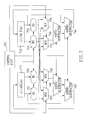
- FIG. 7 shows a CORDIC architecture hardware implementation in accordance with the present invention
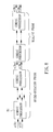
- FIG. 8 shows another CORDIC architecture hardware implementation in accordance with the present invention.
- FIG. 9 shows a performance comparison between EEAS and EES.
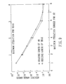
- FIG. 10 shows a performance comparison between the TBS method and the Greedy method.
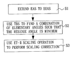
- FIG. 2 shows the flowchart of the CORDIC method applied in vector rotation in accordance with the present invention.
- the present method includes the following three stages: (S1) extending the elementary angle set (EAS) to an extended elementary angle set (EEAS) for executing the CORDIC algorithm; (S2) using a Trellis-based Searching (TBS) method to find a combination of elementary angles from the elementary angles of the EEAS such that the residue angle is minimum; and (S3) using an extended type-II (ET-II) scaling operation to perform the scaling correction.
- S1 extending the elementary angle set (EAS) to an extended elementary angle set (EEAS) for executing the CORDIC algorithm
- S2 using a Trellis-based Searching (TBS) method to find a combination of elementary angles from the elementary angles of the EEAS such that the residue angle is minimum
- TBS Trellis-based Searching
- ET-II extended type-I
- j(0 ⁇ j ⁇ R m ⁇ 1) denotes the iteration index
- s(j) ⁇ 0, 1, . . . , N ⁇ 1 ⁇ is the rotational sequence that determines the micro-rotation angle in the j-th iteration
- a(j) ⁇ 1, 0, 1 ⁇ is the directional sequence that controls the direction of the j-th micro-rotation of 2 ⁇ s(j)
- ⁇ ′(j) is the j-th micro-rotation angle and defined as ⁇ ′(j) ⁇ tan ⁇ 1 (a(j)*2 ⁇ s(j) ).
- equation (6) shows that the AR problem is finding the combination of elements from a set, which consists of all possible values of ⁇ ′(j), so that ⁇ m can be minimized.
- a set is called the elementary angles set (EAS) S 1 , and is defined as
- the EAS S1 is comprised of an arctangent of single signed-power-of-two (SPT) term, i.e., tan ⁇ 1 (a′*2 ⁇ s′ ).
- SPT single signed-power-of-two
- EEAS extended elementary angles set
- s 2 ⁇ tan ⁇ 1 ( a′ 0 *2 ⁇ s′ 0 +a′ 1 *2 ⁇ s′ 1 ): a′ 0 ,a′ 1 ⁇ 1,0,1 ⁇ , s′ 0 ,s′ 1 ⁇ 0,1, . . . , N ⁇ 1 ⁇ .
- Z(S 2 ) states in each step.
- a cumulative angle ⁇ (i,k) is used to denote the best approximation of angle ⁇ in the k-th state up to the i-th step.
- the TBS algorithm can be described as follows:
- the TBS algorithm is started by setting all ⁇ (i,k) as the corresponding elementary angles, that is:
- a path in the trellis which leaves the k-th state at the i-th step and enters the k-th state at the (i+1)-th step, corresponds to an operation of ⁇ (i,k)+r(k′).
- the appended angle of ⁇ (i,k)+r(k′) becomes the candidate for ⁇ (i+1,k′).
- the paths can diverge to all the states at the next search step (i*+1).
- the TBS algorithm involves calculating and minimizing the difference between the target angle ⁇ and ⁇ (i,k) for all k at each search step i.
- ⁇ (i+1,k) is determined by:
- the selected path is denoted as the surviving path.
- the next procedure for the TBS algorithm is to determine the global result, ⁇ TBS . Similar to the determination of the surviving path, the ⁇ TBS is decided as follows:
- ⁇ circumflex over (P) ⁇ denotes the quantized value of P, k(m) ⁇ 1, ⁇ and q(m) ⁇ 0,1, . . . ,W ⁇ 1 , is the counterpart of R m in the micro-rotation phase, determining the number of iterations in the scaling phase.
- FIG. 7 shows a hardware implementation of the CORDIC architecture applied in vector rotation according to the present invention, which is an iterative CORDIC processor. It consists of a control unit 701 , first and second registers 711 and 712 , first to fourth barrel shifters 721 ⁇ 724 , first to fourth multiplexers 731 ⁇ 734 , first to fourth adders/subtracters 741 ⁇ 744 .
- the first register 711 is provided for temporarily storing x(i) or ⁇ tilde over (x) ⁇ (m), and its output terminal is connected to the first and second barrel registers 721 and 722 , and its input terminal is connected to the second adder/subtracter 742 .
- the second register 712 is provided for temporarily storing y(i) or ⁇ tilde over (y) ⁇ (m), and its output terminal is connected to the third and fourth barrel registers 723 and 724 , and its input terminal is connected to the fourth adder/subtractor 744 .
- the output terminal of the first barrel register 721 is connected to the first input terminal of the first multiplexer 731 and the third multiplexer 733 .
- the output terminal of the second barrel register 722 is connected to the first input terminal of the second multiplexer 732 and the fourth multiplexer 734 .
- the output terminal of the third barrel register 723 is connected to the second input terminal of the first multiplexer 731 and the third multiplexer 733 .
- the output terminal of the fourth barrel register 724 is connected to the second input terminal of the second multiplexer 732 and the fourth multiplexer 734 .
- the output terminals of the first and second multiplexers 731 and 732 are connected to the input terminals of the first adder/subtractor 741 .
- the output terminal of the first adder/subtractor 741 is connected to the input terminal of the second adder/subtractor 742 .
- the output terminals of the third and fourth multiplexers 733 and 734 are connected to the input terminals of the third adder/subtractor 743 .
- the output terminal of the third adder/subtractor 743 is connected to the input terminal of the fourth adder/subtractor 744 .
- the output terminals of the second and fourth adders/subtractors 742 and 744 are connected to the input terminals of the first and second register 711 and 712 , respectively.
- the control unit 701 is provided to control the first to fourth barrel shifters 721 ⁇ 724 , the first to fourth multiplexers 731 ⁇ 734 , and the first to fourth adders/subtractors 741 ⁇ 744 , so as to implement the CORDIC algorithm.
- Two separate phases are performed to complete a single CORDIC rotation, i.e., the micro-rotational phase and the scaling phase.
- the first and second barrel shifters 721 and 722 are shifted by s 1 (i) and s 0 (i) bits, respectively.
- the third and fourth barrel shifters 723 and 724 are shifted by s 0 (i) and s 1 (i) bits, respectively.
- the second input terminals of the first and second multiplexers 731 and 732 are switched to connect to their output terminals thereof, respectively.
- the first input terminals of the third and fourth multiplexers 733 and 734 are switched to connect to their output terminals thereof, respectively.
- the control unit 701 uses a 0 (i) and a 1 (i) to control first to fourth adders/subtracters 741 ⁇ 744 , so as to perform addition and subtraction.
- the first and second barrel shifters 721 and 722 are shifted by q 1 (m) and q 0 (m) bits, respectively.
- the third and fourth barrel shifters 723 and 724 are shifted by q 0 (m) and q 1 (m) bits, respectively.
- the first input terminals of the first and second multiplexers 731 and 732 are switched to connect to their output terminals thereof, respectively.
- the second input terminals of the third and fourth multiplexers 733 and 734 are switched to connect to their output terminals thereof, respectively.
- the control unit 701 uses k 0 (m) and k 1 (m) to control the first to fourth adders/subtracters 741 ⁇ 744 , so as to perform addition and subtraction.
- FIG. 8 By unfolding the iterative implementation of the above CORDIC processor, a parallel structure can be obtained as depicted in FIG. 8.
- the structure is composed of (R m +R s ) CORDIC processors 81 connected in cascade form, in which the R m leading processors 81 perform the micro-rotations and the following R s processors 81 execute the scaling operations.
- Each CORDIC processor 81 performs one iteration as specified in FIG. 7.
- the present invention performs the CORDIC algorithm by extending EAS to EEAS.
- FIG. 9 that gives the comparison of the maximum iteration number and residue angle error between EEAS and EAS
- EEAS can have a smaller residue angle error with less iteration number.
- FIG. 10 shows an experimental result in which the TBS method requires a smaller iteration number than the conventional Greedy method, and the combination of EEAS and TBS methods can further reduce the iteration number.
Abstract
A CORDIC method and a CORDIC architecture applied in vector rotation are disclosed. An elementary angles set is extended by representing the elementary angles as the arctangent of the sum of two single signed-power-of-two terms to an extended elementary angles set. A combination of elementary angles is found from the extended elementary angles set such that the residue angle error can be minimized. A quantized scaling factor is used to scale the combination of elementary angles after being micro-rotated.
Description
- 1. Field of the Invention
- The present invention relates to a COordinate Rotational DIgital Computer (CORDIC) method and a CORDIC architecture applied in vector rotation, and more particularly, to a CORDIC method based on Extended Elementary-Angle Sets (EEAS) and Trellis-based Searching (TBS) and its architecture.
- 2.Description of Related Art
- Currently, vector rotation is the kernel of various digital signal-processing applications, including discrete orthogonal transformations, lattice-based digital filtering, matrix computation, complex-valued number manipulation, etc. In X-Y coordinates one vector rotation operation can be expressed as:

- FIG. 1 shows hardware architecture used to implement the vector rotation operation, which requires four adders and two multipliers. That is, the execution of one vector rotation operation will require executing four addition operations and two multiplication operations. The complexity of such an execution is too high. Reducing the wordlength can decrease the complexity. However, the SQNR will be increased accordingly.
- The CORDIC algorithm is a well-known iterative method for the computation of vector rotation, which requires only one shift operation and one addition operation to perform a vector rotation operation. The CORDIC algorithm decomposes the rotation angle θ into a combination of pre-defined elementary angles as follows:

- where N is the number of elementary angles, μ={1, −1} is the
rotation 5 sequence which determines the direction of the i-th elementary angle of a(i)=tan−1(2−i), and ε denotes the residue angle. - Based on equation (1), the recurrence equations of the CORDIC algorithm can be written as

- for i=0, 1, . . . , N−1. In practical fixed-point implementation, for data wordlength of W bits, no more than W iterations of the recurrence relation in equation (2) need be performed, i.e., N≦W. Also, the final values, x(N) and y(N), need to be scaled by an accumulated scaling factor expressed as follows:

- In the above CORDIC algorithm, each elementary angle needs to be performed sequentially so as to complete the micro-rotation phase. However, in the applications where the rotation angles are known in advance, it would be advantageous to relax the sequential constraint on the micro-rotation phase. The angle recoding (AR) technique is done by extending the set of μ(i) from {1, −1} to {1, −1, 0}. By substituting μ(i)=0 into equation (2), one can skip the micro-rotation of the elementary angle a(i )=tan −1(2−i). Nevertheless, the AR technique imposes no restriction on the iteration number. Rotation angles of different values may need unequal numbers of iterations, which may lead to bus/timing alignment problems in VLSI circuits. Therefore, it is desired for the above CORDIC algorithm to be improved to mitigate and/or obviate the aforementioned problems.
- The object of the present invention is to provide a CORDIC method and a CORDIC architecture applied in vector rotation, which can effectively improve SQNR performance, reduce the number of iterations and decrease the hardware complexity.
- In accordance with one aspect of the present invention, a CORDIC method applied in vector rotation is provided, which first extends an elementary angles set:
- S 1={tan−1(a′*2−s′ 1 ):a′∈{−1,0,1},s′∈{0,1, . . . ,N−1}},
- by representing the elementary angles as the arctangent of the sum of two single signed-power-of-two (SPT) terms (a′*2 −s′) to an extended elementary angles set:
- s 2={tan −1(a′ 0*2−s′ 0 +a′ 1*2−s′ 1 ):a′ 0 ,a′ 1∈{−1,0,1,},s′ 0 ,s′ 1∈{0,1, . . . ,N−1}},
- where N is the number of elementary angles. Next, a combination of elementary angles is found from the extended elementary angles set such that the residue angle error:

- can be minimized, where θ is a target angle; R m is the maximum iteration number; j denotes the iteration index; s0(j), s1(j)∈{0, 1, . . . , N−1} are the rotational sequences; a0(j), a1(j) control the direction of j-th micro-rotation of 2−S 0 (j), 2−S 1 (j). Then, a quantized scaling factor is used to scale the combination of elementary angles determined in step (B) after being micro-rotated.
- In accordance with another aspect of the present invention, a CORDIC processor applied in vector rotation is provided for performing micro-rotational phase operations:

- scaling phase operations:

- In the CORDIC processor, a first register is provided for temporarily storing x(i) or {tilde over (x)}(m). A second register is provided for temporarily storing y(i) or {tilde over (y)}(m) . First and second barrel shifters have input terminals connected to output terminals of the first register. Third and fourth barrel shifters have input terminals connected to output terminals of the second register. A first multiplexer has a first input terminal connected to an output terminal of the first barrel shifter, and a second input terminal connected to an output terminal of the third barrel shifter. A second multiplexer has a first input terminal connected to an output terminal of the second barrel shifter, and a second input terminal connected to an output terminal of the fourth barrel shifter. A third multiplexer has a first input terminal connected to the output terminal of the first barrel shifter, and a second input terminal connected to an output terminal of the third barrel shifter. A fourth multiplexer has a first input terminal connected to the output terminal of the second barrel shifter, and a second input terminal connected to the output terminal of the fourth barrel shifter. A first adder/subtractor has two input terminals connected to output terminals of the first and second multiplexers, respectively. A second adder/subtractor has two input terminals connected to output terminals of the first adder/subtractor and first register, respectively, and an output terminal connected to an input terminal of the first register. A third adder/subtractor has two input terminals connected to output terminals of the third and fourth multiplexers, respectively. A fourth adder/subtractor has two input terminals connected to output terminals of the third adder/subtractor and second register, respectively, and an output terminal connected to an input terminal of the second register. A control unit controls the first to fourth barrel shifters, the first to fourth multiplexers, and the first to fourth adders/subtractors to perform the CORDIC operation iteratively.
- In accordance with still another object of the present invention, a CORDIC architecture applied in vector rotation is provided having (R m+Rs) CORDIC processors connected in cascade form, in which the Rm leading processors are used in the micro-rotation phase and the following Rs processors are used in the scaling phase.
- Other objects, advantages, and novel features of the invention will become more apparent from the following detailed description when taken in conjunction with the accompanying drawings.
- FIG. 1 shows a conventional hardware architecture for implementing vector rotation;
- FIG. 2 is the flowchart of the CORDIC method in accordance with the present invention;
- FIG. 3 schematically illustrates the initialization and transfer path of the TBS algorithm;
- FIG. 4 schematically illustrates an accumulation step example in the TBS algorithm;
- FIG. 5 schematically illustrates a selection step example in the TBS algorithm;
- FIG. 6 schematically illustrates a trace back step example in the TBS algorithm;
- FIG. 7 shows a CORDIC architecture hardware implementation in accordance with the present invention;
- FIG. 8 shows another CORDIC architecture hardware implementation in accordance with the present invention;
- FIG. 9 shows a performance comparison between EEAS and EES; and
- FIG. 10 shows a performance comparison between the TBS method and the Greedy method.
- FIG. 2 shows the flowchart of the CORDIC method applied in vector rotation in accordance with the present invention. As shown the present method includes the following three stages: (S1) extending the elementary angle set (EAS) to an extended elementary angle set (EEAS) for executing the CORDIC algorithm; (S2) using a Trellis-based Searching (TBS) method to find a combination of elementary angles from the elementary angles of the EEAS such that the residue angle is minimum; and (S3) using an extended type-II (ET-II) scaling operation to perform the scaling correction.
- To depict the EEAS in the first stage, a parameter R m is employed to be the maximum iteration number in the AR technique. Therefore, the AR problem can be summarized as:
- Given a target angle θ and the maximum iteration number R m, find the rotation sequence μ(i)∈{1,−1,0} for 0≦i≦N−1, such that the residue angle error:

- is minimized subject to the constraint:

- To facilitate the derivation of the present EEAS scheme, the AR problem described above is rewritten in an alternative form. The reformulation is done by removing the redundant iterations of μ(i)=0 in equation (4), changing the variables and index, and using the equality ±tan −1(A)=tan−1(±A). Then, the equations (4) and (5) can be recast in a single compact form as:

- where j(0≦j≦R m−1) denotes the iteration index; s(j)∈{0, 1, . . . , N−1} is the rotational sequence that determines the micro-rotation angle in the j-th iteration; a(j)∈{−1, 0, 1} is the directional sequence that controls the direction of the j-th micro-rotation of 2−s(j):θ′(j) is the j-th micro-rotation angle and defined as θ′(j)≡tan−1(a(j)*2−s(j)).
- Therefore, equation (6) shows that the AR problem is finding the combination of elements from a set, which consists of all possible values of θ′(j), so that ε m can be minimized. Such a set is called the elementary angles set (EAS) S1, and is defined as
- S 1={tan−1(a′*2−s′):a′∈{−1,0,1},s′∈{0,1, . . . ,N−1}}. (7)
- By observing equation (7), it is seen that the EAS S1 is comprised of an arctangent of single signed-power-of-two (SPT) term, i.e., tan −1(a′*2−s′). By representing the elementary angles as the arctangent of the sum of two SPT terms, the EAS S1 can be extended to an extended elementary angles set (EEAS) S2 as follows:
- s 2={tan−1(a′ 0*2−s′ 0 +a′ 1*2−s′ 1 ):a′ 0 ,a′ 1∈{−1,0,1{,s′ 0 ,s′ 1∈{0,1, . . . ,N−1}}. (8)
- Based on the EEAS S 2 developed in equation (8), the recurrence equations of the CORDIC algorithm can be modified as:

- for 0≦j≦R−1, where a 0(j), a1(j), s0(j) and s1(j) denote the parameters to control the j-th micro-rotation of the elementary angle of tan−1(a0(j)*2−S 0 (j)+a1(j)*2−S 1 (j)).
- With the above EEAS S 2 and given θ and Rm, it is desired to find the parameters of a0(j), a1(j), s0(j) and s1(j) (i.e., the combination of elementary angles from EEAS S2), such that the residue angle error:

- can be minimized.
- In the second stage of processing, the TBS algorithm is employed to find the combination of elementary angles, wherein Z(S 2) denotes the number of the elementary angles in the extended set S2, and each distinct elementary angle in the set is expressed as r(k), for 1≦k≦Z(S2), i.e., S2={r(1), r(2), . . . , r(Z(S2))}. Moreover, in the TBS algorithm, there are Z(S2) states in each step. For the k-th state (1≦k≦Z(S2)) of the i-th search step, a cumulative angle Φ(i,k) is used to denote the best approximation of angle θ in the k-th state up to the i-th step. The TBS algorithm can be described as follows:
- (1) Initialization Step:
- The TBS algorithm is started by setting all Φ(i,k) as the corresponding elementary angles, that is:
- Φ(1,k)=r(k) for all k. (11)
- Taking Z(S 2)=15 as an example, the initialization and transfer paths of the TBS algorithm are illustrated in FIG. 3.
- (2) Accumulation Step
- A path in the trellis, which leaves the k-th state at the i-th step and enters the k-th state at the (i+1)-th step, corresponds to an operation of Φ(i,k)+r(k′). For all paths, the appended angle of Φ(i,k)+r(k′) becomes the candidate for Φ(i+1,k′). As shown in FIG. 4, from a given state at step i=i*, the paths can diverge to all the states at the next search step (i*+1). Namely, there are Z(S 2) paths, carrying the corresponding appended angles of Φ(i,k)+r(k′) for all k, entering the k′-th state at the (i*+1)-th step. Then, those appended angles form the candidate set for the cumulative angle of Φ(i*+1,k′).
- (3) Comparison and Selection Step
- The TBS algorithm involves calculating and minimizing the difference between the target angle θ and Φ(i,k) for all k at each search step i. To be specific, Φ(i+1,k) is determined by:
- Φ(i+1,k)=min{|Φ(i,k*)+r(k)−θ|:1≦k*≦Z(S 2){. (12)
- Then, the selected path is denoted as the surviving path. After calculating all the cumulative angles Φ(i,k) for all k, their corresponding surviving paths can be obtained. Continuing in this manner and moving to the (i+1)-th step until reaching the maximum iteration number (i=Rm), Φ(R m,k) can be obtained for 1≦k≦Z(S2). Consider the example, in which i=2 and k=12. The process of equation (12) is illustrated in FIG. 5. From those 15 paths entering the 12th state at the 3rd search step, the path, of which the appended angle Φ(2, j)+r(12) is closest to θ=π/3, is selected as the surviving path. In this case, the third path (k*=3), which is marked by the solid line, is selected. Then, the resultant angle is assigned to Φ(3,12) for the subsequent search process.
- (4) Determination of the Global Result and Trace Back Step
- After calculating the cumulative angles for all states at the last search step, i.e., Φ(R m,k) for 1≦k≦Z(S2), the next procedure for the TBS algorithm is to determine the global result, θTBS. Similar to the determination of the surviving path, the θTBS is decided as follows:
- θTBS =min{|Φ(R m ,K′)−θ|:1≦k′≦Z(S 2){. (13)
- Next, all the micro-rotations can be determined by tracing back from the state, whose corresponding Φ(R m,k) is the best approximation of θ, along with its surviving backward path.
- The procedure for trace back is illustrated in FIG. 6. All the surviving paths for each state at each step (except i=1) are represented by the dashed line. First, Φ(4,13) is selected as the global result. Then, it is traced along the surviving path that connects the 13th state at the final backward step. Next, it finds the state from which the surviving path leaves in the previous step. By doing the process repeatedly, the global surviving path of the TBS algorithm can be determined, as marked by the solid line in. By traveling along the surviving global path, the algorithm is able to find the visited states and read all the micro-rotation angles that form the global result θ TBS. In this case, Φ(4,13)=r(9)+r(13)+r(2)+r(13), which is the best approximation of angle θ generated by the present TBS algorithm.
- When considering that each micro rotation will scale up the norm of a vector, in the known type-II scaling operation, the accumulated scaling factor P is quantized as:

- where {circumflex over (P)} denotes the quantized value of P, k(m)∈{1,−} and q(m)∈{0,1, . . . ,W−1, is the counterpart of Rm in the micro-rotation phase, determining the number of iterations in the scaling phase. With this type-II scaling operation, and by increasing the number of possible values that can be represented by (1+k(m)·2
−q(m) ), we obtain a similar derivation of the EEAS scheme that employs one extra SPT term in equation (14):
- where
- k 0 (m)|{1,−1,0},k 1 (m)∈{1,−1,0},q 0 (m)∈{0,1, . . . ,W−1},
- and
- q 1 (m)∈{0,1, . . . ,W−1}.
- By doing so, it is expected to obtain more accurate approximations of P. The scaling operation can be accomplished within R s, iterations by using the recurrence equations:

- wherein the initial settings for the scaling phase are set as {tilde over (x)}(0)=x(R m) and {tilde over (y)}(0)=y(Rm).
- FIG. 7 shows a hardware implementation of the CORDIC architecture applied in vector rotation according to the present invention, which is an iterative CORDIC processor. It consists of a
control unit 701, first andsecond registers fourth barrel shifters 721˜724, first tofourth multiplexers 731˜734, first to fourth adders/subtracters 741˜744. - The
first register 711 is provided for temporarily storing x(i) or {tilde over (x)}(m), and its output terminal is connected to the first and second barrel registers 721 and 722, and its input terminal is connected to the second adder/subtracter 742. Thesecond register 712 is provided for temporarily storing y(i) or {tilde over (y)}(m), and its output terminal is connected to the third and fourth barrel registers 723 and 724, and its input terminal is connected to the fourth adder/subtractor 744. - The output terminal of the
first barrel register 721 is connected to the first input terminal of thefirst multiplexer 731 and thethird multiplexer 733. The output terminal of thesecond barrel register 722 is connected to the first input terminal of thesecond multiplexer 732 and thefourth multiplexer 734. The output terminal of thethird barrel register 723 is connected to the second input terminal of thefirst multiplexer 731 and thethird multiplexer 733. The output terminal of thefourth barrel register 724 is connected to the second input terminal of thesecond multiplexer 732 and thefourth multiplexer 734. - The output terminals of the first and
second multiplexers subtractor 741. The output terminal of the first adder/subtractor 741 is connected to the input terminal of the second adder/subtractor 742. The output terminals of the third andfourth multiplexers subtractor 743. The output terminal of the third adder/subtractor 743 is connected to the input terminal of the fourth adder/subtractor 744. The output terminals of the second and fourth adders/subtractors second register - The
control unit 701 is provided to control the first tofourth barrel shifters 721˜724, the first tofourth multiplexers 731˜734, and the first to fourth adders/subtractors 741˜744, so as to implement the CORDIC algorithm. Two separate phases are performed to complete a single CORDIC rotation, i.e., the micro-rotational phase and the scaling phase. In the micro-rotational phase, under the control of thecontrol unit 701, the first andsecond barrel shifters fourth barrel shifters second multiplexers fourth multiplexers control unit 701 uses a0(i) and a1(i) to control first to fourth adders/subtracters 741˜744, so as to perform addition and subtraction. - In the scaling phase, under the control of the
control unit 701, the first andsecond barrel shifters fourth barrel shifters second multiplexers fourth multiplexers control unit 701 uses k0(m) and k1(m) to control the first to fourth adders/subtracters 741˜744, so as to perform addition and subtraction. - By unfolding the iterative implementation of the above CORDIC processor, a parallel structure can be obtained as depicted in FIG. 8. The structure is composed of (R m+Rs)
CORDIC processors 81 connected in cascade form, in which the Rm leading processors 81 perform the micro-rotations and the following Rs processors 81 execute the scaling operations. EachCORDIC processor 81 performs one iteration as specified in FIG. 7. - In view of the foregoing, it is known that the present invention performs the CORDIC algorithm by extending EAS to EEAS. As shown in FIG. 9 that gives the comparison of the maximum iteration number and residue angle error between EEAS and EAS, it is known that EEAS can have a smaller residue angle error with less iteration number. FIG. 10 shows an experimental result in which the TBS method requires a smaller iteration number than the conventional Greedy method, and the combination of EEAS and TBS methods can further reduce the iteration number.
- Although the present invention has been explained in relation to its preferred embodiment, it is to be understood that many other possible modifications and variations can be made without departing from the spirit and scope of the invention as hereinafter claimed.
Claims (12)
1. A CORDIC method applied in vector rotation comprising the steps of:

(A) extending an elementary angles set:
S 1={tan−1(a′*2−s′):a′∈{−1,0,1{,s′∈{0,1, . . . ,N−1}},
by representing the elementary angles as the arctangent of the sum of two single signed-power-of-two (SPT) terms (a′*2−s′) to an extended elementary angles set:
s 2={tan−1(a′ 0*2−s′ 0 +a′ 1*2−s′ 1 ):a′ 0 ,a′ 1∈{−1,0,1},s′ 0 ,s′ 1∈{0,1, . . . ,N−1}},
where N is the number of elementary angles;
(B) finding a combination of elementary angles from the extended elementary angles set such that the residue angle error:
can be minimized, where θ is a target angle; Rm is the maximum iteration number; j denotes the iteration index; s0(j),s1(j),∈{0,1, . . . , N−1} are the rotational sequences; a0(j), a1(j), control direction of j-th micro-rotation of 2−S 0 (j), 2−S 1 (j); and
(C) using a quantized scaling factor to scale the combination of elementary angles determined in step (B) after being micro-rotated.
2. The method as claimed in claim 1 , wherein, based on the extended elementary angles set of step (A), the CORDIC method is performed by the recurrence equations:

for 0≦j≦Rm−1, where a0(j), a1(j), s0(j) and s1(j) denote parameters to control the j-th micro-rotation of tan−1(a0(j)*2−S 0 (j)+a1(j)*2−S 1 (j))′s elementary angle.
3. The method as claimed in claim 1 , wherein, in step (B), a Trellis-based Searching (TBS) method is employed to find the combination of elementary angles, and the TBS method uses a cumulative angle Φ(i,k) to denote the best approximation of angle θ in a k-th state up to an i-th step; the TBS method comprises the steps of:
(B1) setting all Φ(i,k) as the corresponding elementary angles r(k);
(B2) for a path which leaves the k-th state at the i-th step and enters the k-th state at the (i+1)-th step, corresponding to an operation of Φ(i,k)+r(k′), and for all paths, taking Φ(i,k)+r(k′) as the candidate for Φ(i+1,k′)
(B3) comparing all candidates for Φ(i+1,k) at each search step, so as to select a candidate closest to the target angle θ as Φ(i+1,k) and record the corresponding path as a surviving path; and
(B4) after calculating the cumulative angles for all states at the last search step, selecting a cumulative angle closest to the target angle θ for use as a global result θTBS, and tracing along its surviving path backward to determine all micro-rotations.
4. The method as claimed in claim 3 , wherein, in step (B3), Φ(i+1,k) is determined by:
Φ(i+1,k)=min {|Φ(i,k*)+r(k)−θ|:1≦k*≦Z(S 2)},
where Z(S2) denotes the number of elementary angles in an extended set S2.
5. The method as claimed in claim 4 , wherein, in step (B4), θTBS is decided by:
θTBS =min {|Φ(R m ,k′)−θ|:1≦k′≦Z(S 2)}.
6. The method as claimed in claim 1 , wherein, in step (C), the quantized scaling factor is:

where k0(m)∈{1,−1,0}, k1(m)∈{1,−1,0}, q0(m)∈{0,1, . . . ,W−1}, q1(m)∈{0,1, . . . ,W−1}, and Rs is a counterpart of Rm in the micro-rotation phase.
7. The method as claimed in claim 6 , wherein step (C) accomplishes scaling operations within R, iterations by using recurrence equations:

8. The method as claimed in claim 6 , wherein the scaling operation is initialized as {tilde over (x)}(0)=x(R m ) and {tilde over (y)}(0)=y(R m ).
9. A CORDIC processor applied in vector rotation for performing micro-rotational phase operations:

scaling phase operations:

the processor comprising:
a first register for temporarily storing x(i) or {tilde over (x)}(m);
a second register for temporarily storing y(i) or {tilde over (y)}(m);
first and second barrel shifters having input terminals connected to output terminals of the first register;
third and fourth barrel shifters having input terminals connected to output terminals of the second register;
a first multiplexer having a first input terminal connected to an output terminal of the first barrel shifter, and a second input terminal connected to an output terminal of the third barrel shifter;
a second multiplexer having a first input terminal connected to an output terminal of the second barrel shifter, and a second input terminal connected to an output terminal of the fourth barrel shifter;
a third multiplexer having a first input terminal connected to the output terminal of the first barrel shifter, and a second input terminal connected to an output terminal of the third barrel shifter;
a fourth multiplexer having a first input terminal connected to the output terminal of the second barrel shifter, and a second input terminal connected to the output terminal of the fourth barrel shifter;
a first adder/subtractor having two input terminals connected to output terminals of the first and second multiplexers, respectively;
a second adder/subtractor having two input terminals connected to output terminals of the first adder/subtractor and first register, respectively, and an output terminal connected to an input terminal of the first register;
a third adder/subtractor having two input terminals connected to output terminals of the third and fourth multiplexers, respectively;
a fourth adder/subtractor having two input terminals connected to output terminals of the third adder/subtractor and second register, respectively, and an output terminal connected to an input terminal of the second register; and
a control unit for controlling the first to fourth barrel shifters, the first to fourth multiplexers, and the first to fourth adders/subtractors to perform CORDIC operations iteratively.
10. The processor as claimed in claim 9 , wherein, in the micro-rotational phase, the first and second barrel shifters are shifted by s1(i) and s0(i) bits, respectively; the third and fourth barrel shifters are shifted by s0(i) and s1(i) bits, respectively; the second input terminals of the first and second multiplexers are switched to connect to their output terminals, respectively; the first input terminals of the third and fourth multiplexers are switched to connect to their output terminals, respectively; the first to fourth adders/subtracters perform addition and subtraction under the control of a0(i) and a1(i).
11. The processor as claimed in claim 9 , wherein, in the scaling phase, the first and second barrel shifters are shifted by q1(m) and q0(m) bits, respectively; the third and fourth barrel shifters are shifted by q0(m) and q1(m) bits, respectively; the first input terminals of the first and second multiplexers are switched to connect to their output terminals, respectively; the second input terminals of the third and fourth multiplexers are switched to connect to their output terminals, respectively; the first to fourth adders/subtracters perform addition and subtraction under the control of k0(m) and k1(m).
12. A CORDIC architecture applied in vector rotation comprising (Rm+Rs) CORDIC processors as claimed in claim 9 connected in cascade form, in which the Rm leading processors are used in the micro-rotational phase and the following Rs processors are used in the scaling phase.
Applications Claiming Priority (2)
| Application Number | Priority Date | Filing Date | Title |
|---|---|---|---|
| TW90127085 | 2001-10-31 | ||
| TW090127085A TW583579B (en) | 2001-10-31 | 2001-10-31 | Computation method and structure of coordinate rotational digital computer applied in vector rotator |
Publications (2)
| Publication Number | Publication Date |
|---|---|
| US20030097388A1 true US20030097388A1 (en) | 2003-05-22 |
| US7047269B2 US7047269B2 (en) | 2006-05-16 |
Family
ID=21679625
Family Applications (1)
| Application Number | Title | Priority Date | Filing Date |
|---|---|---|---|
| US10/138,652 Expired - Lifetime US7047269B2 (en) | 2001-10-31 | 2002-05-06 | Cordic method and architecture applied in vector rotation |
Country Status (2)
| Country | Link |
|---|---|
| US (1) | US7047269B2 (en) |
| TW (1) | TW583579B (en) |
Cited By (7)
| Publication number | Priority date | Publication date | Assignee | Title |
|---|---|---|---|---|
| US20050198089A1 (en) * | 2004-03-08 | 2005-09-08 | Industrial Technology Research Institute | Mixed-scaling-rotation CORDIC method with scaling-free rotational operations for vector rotation |
| US20060059215A1 (en) * | 2001-12-20 | 2006-03-16 | Koushik Maharatna | Cordic unit |
| US20070155311A1 (en) * | 2000-09-13 | 2007-07-05 | Stratosaudio, Inc. | Broadcast response system |
| US20080140239A1 (en) * | 2000-03-08 | 2008-06-12 | Music Choice | Personalized Audio System and Method |
| CN102323878A (en) * | 2011-05-31 | 2012-01-18 | 电子科技大学 | Circuit device and method for norm correction of CORDIC (Coordinated Rotation Digital Computer) algorithm |
| CN103914625A (en) * | 2014-04-10 | 2014-07-09 | 电子科技大学 | Wireless signal direction-finding method based on CORDIC (coordinated rotation digital computer) algorithm |
| US9591051B2 (en) | 2000-03-08 | 2017-03-07 | Music Choice | Systems and methods for providing customized media channels |
Families Citing this family (5)
| Publication number | Priority date | Publication date | Assignee | Title |
|---|---|---|---|---|
| US20050216540A1 (en) * | 2004-03-25 | 2005-09-29 | Wen Kuei-Ann | Novel CORDIC circuit |
| WO2009034517A2 (en) * | 2007-09-10 | 2009-03-19 | St-Nxp Wireless (Holding) Ag | Electronic device, barrel shifter unit and method of barrel shifting |
| US8706787B2 (en) * | 2007-09-26 | 2014-04-22 | Nec Corporation | CORDIC-based FFT and IFFT apparatus and method |
| TWI376633B (en) * | 2008-12-19 | 2012-11-11 | Ind Tech Res Inst | Method of cordic computing vector angle and electronic apparatus using the same |
| RU2683182C1 (en) * | 2017-12-21 | 2019-03-26 | Акционерное общество "Ангстрем" (АО "Ангстрем") | Asynchronous vector turn device |
Citations (2)
| Publication number | Priority date | Publication date | Assignee | Title |
|---|---|---|---|---|
| US20030050949A1 (en) * | 2000-09-12 | 2003-03-13 | Van Wechel Robert J. | Simultaneous computation of multiple complex number multiplication products |
| US20030206600A1 (en) * | 1999-04-23 | 2003-11-06 | Nokia Networks Oy | QAM Modulator |
-
2001
- 2001-10-31 TW TW090127085A patent/TW583579B/en not_active IP Right Cessation
-
2002
- 2002-05-06 US US10/138,652 patent/US7047269B2/en not_active Expired - Lifetime
Patent Citations (3)
| Publication number | Priority date | Publication date | Assignee | Title |
|---|---|---|---|---|
| US20030206600A1 (en) * | 1999-04-23 | 2003-11-06 | Nokia Networks Oy | QAM Modulator |
| US20030050949A1 (en) * | 2000-09-12 | 2003-03-13 | Van Wechel Robert J. | Simultaneous computation of multiple complex number multiplication products |
| US20040039761A1 (en) * | 2000-09-12 | 2004-02-26 | Wechel Robert J. Van | Systems and methods for extracting coherent correlation data |
Cited By (9)
| Publication number | Priority date | Publication date | Assignee | Title |
|---|---|---|---|---|
| US20080140239A1 (en) * | 2000-03-08 | 2008-06-12 | Music Choice | Personalized Audio System and Method |
| US8051146B2 (en) | 2000-03-08 | 2011-11-01 | Music Choice | Personalized audio system and method |
| US9591051B2 (en) | 2000-03-08 | 2017-03-07 | Music Choice | Systems and methods for providing customized media channels |
| US20070155311A1 (en) * | 2000-09-13 | 2007-07-05 | Stratosaudio, Inc. | Broadcast response system |
| US20060059215A1 (en) * | 2001-12-20 | 2006-03-16 | Koushik Maharatna | Cordic unit |
| US7606852B2 (en) * | 2001-12-20 | 2009-10-20 | IHP-GmbH-Innovations for High Performance Microelectronics/Institut fur Innovative Mikroelectronik | CORDIC unit |
| US20050198089A1 (en) * | 2004-03-08 | 2005-09-08 | Industrial Technology Research Institute | Mixed-scaling-rotation CORDIC method with scaling-free rotational operations for vector rotation |
| CN102323878A (en) * | 2011-05-31 | 2012-01-18 | 电子科技大学 | Circuit device and method for norm correction of CORDIC (Coordinated Rotation Digital Computer) algorithm |
| CN103914625A (en) * | 2014-04-10 | 2014-07-09 | 电子科技大学 | Wireless signal direction-finding method based on CORDIC (coordinated rotation digital computer) algorithm |
Also Published As
| Publication number | Publication date |
|---|---|
| TW583579B (en) | 2004-04-11 |
| US7047269B2 (en) | 2006-05-16 |
Similar Documents
| Publication | Publication Date | Title |
|---|---|---|
| US7047269B2 (en) | Cordic method and architecture applied in vector rotation | |
| US6901422B1 (en) | Matrix multiplication in a vector processing system | |
| US6243732B1 (en) | Data processor and data processing system | |
| Lakshmi et al. | CORDIC architectures: A survey | |
| Dawid et al. | CORDIC algorithms and architectures | |
| JP2007520009A (en) | Implementation of the CORDIC algorithm for complex phase rotation | |
| JPH0635680A (en) | Digital circuit computing logarithm and method of operating computer system | |
| JPH05241794A (en) | Device for approximating transcendental function and its method | |
| KR100744216B1 (en) | Device and method for calculating a multiplication involving a shifting of the multiplicand | |
| EP0744054A1 (en) | High speed function generating apparatus and method | |
| JP2822399B2 (en) | Logarithmic function arithmetic unit | |
| US20010054051A1 (en) | Discrete cosine transform system and discrete cosine transform method | |
| JP2617733B2 (en) | Elementary function arithmetic unit | |
| Villalba et al. | Parallel compensation of scale factor for the CORDIC algorithm | |
| Sahoo et al. | Hardware implementation of CORDIC algorithm | |
| US6055553A (en) | Apparatus for computing exponential and trigonometric functions | |
| Hormigo et al. | CORDIC processor for variable-precision interval arithmetic | |
| Maharatna et al. | A CORDIC like processor for computation of arctangent and absolute magnitude of a vector | |
| Dawid et al. | High speed bit-level pipelined architectures for redundant CORDIC implementation | |
| US20050198089A1 (en) | Mixed-scaling-rotation CORDIC method with scaling-free rotational operations for vector rotation | |
| Götze | Iterative version of the QRD for adaptive recursive least squares (RLS) filtering | |
| Kuhlmann et al. | A novel CORDIC rotation method for generalized coordinate systems | |
| Lin et al. | A CORDIC algorithm with fast rotation prediction and small iteration number | |
| Lakshmi et al. | High speed architectural implementation of CORDIC algorithm | |
| Wu et al. | A novel trellis-based searching scheme for EEAS-based CORDIC algorithm |
Legal Events
| Date | Code | Title | Description |
|---|---|---|---|
| AS | Assignment |
Owner name: INDUSTRIAL TECHNOLOGY RESEARCH INSTITUTE, TAIWAN Free format text: ASSIGNMENT OF ASSIGNORS INTEREST;ASSIGNORS:WU, CHENG-SHING;PAN, CHIA-HO;WU, AN-YEU;REEL/FRAME:012869/0665 Effective date: 20020418 |
|
| STCF | Information on status: patent grant |
Free format text: PATENTED CASE |
|
| FPAY | Fee payment |
Year of fee payment: 4 |
|
| FPAY | Fee payment |
Year of fee payment: 8 |
|
| MAFP | Maintenance fee payment |
Free format text: PAYMENT OF MAINTENANCE FEE, 12TH YEAR, LARGE ENTITY (ORIGINAL EVENT CODE: M1553) Year of fee payment: 12 |