US20030094040A1 - Multi-probe pressure transient analysis for determination of horizontal permeability, anisotropy and skin in an earth formation - Google Patents
Multi-probe pressure transient analysis for determination of horizontal permeability, anisotropy and skin in an earth formation Download PDFInfo
- Publication number
- US20030094040A1 US20030094040A1 US10/254,310 US25431002A US2003094040A1 US 20030094040 A1 US20030094040 A1 US 20030094040A1 US 25431002 A US25431002 A US 25431002A US 2003094040 A1 US2003094040 A1 US 2003094040A1
- Authority
- US
- United States
- Prior art keywords
- probe
- formation
- pressure
- permeability
- source
- Prior art date
- Legal status (The legal status is an assumption and is not a legal conclusion. Google has not performed a legal analysis and makes no representation as to the accuracy of the status listed.)
- Granted
Links
Images


Classifications
-
- E—FIXED CONSTRUCTIONS
- E21—EARTH DRILLING; MINING
- E21B—EARTH DRILLING, e.g. DEEP DRILLING; OBTAINING OIL, GAS, WATER, SOLUBLE OR MELTABLE MATERIALS OR A SLURRY OF MINERALS FROM WELLS
- E21B49/00—Testing the nature of borehole walls; Formation testing; Methods or apparatus for obtaining samples of soil or well fluids, specially adapted to earth drilling or wells
- E21B49/008—Testing the nature of borehole walls; Formation testing; Methods or apparatus for obtaining samples of soil or well fluids, specially adapted to earth drilling or wells by injection test; by analysing pressure variations in an injection or production test, e.g. for estimating the skin factor
-
- E—FIXED CONSTRUCTIONS
- E21—EARTH DRILLING; MINING
- E21B—EARTH DRILLING, e.g. DEEP DRILLING; OBTAINING OIL, GAS, WATER, SOLUBLE OR MELTABLE MATERIALS OR A SLURRY OF MINERALS FROM WELLS
- E21B49/00—Testing the nature of borehole walls; Formation testing; Methods or apparatus for obtaining samples of soil or well fluids, specially adapted to earth drilling or wells
- E21B49/08—Obtaining fluid samples or testing fluids, in boreholes or wells
- E21B49/10—Obtaining fluid samples or testing fluids, in boreholes or wells using side-wall fluid samplers or testers
Definitions
- the preferred embodiments of the present invention generally relate to determining hydraulic permeability of earth formations traversed by a borehole. More particularly, the preferred embodiments are directed to determining permeability anisotropy of the earth formations. More particularly still, the preferred embodiments are directed to determining the hydraulic permeability, permeability anisotropy and skin using an analytic model that considers the storage effect downhole, as well as the dip angle of the formation relative to the borehole.
- Permeability is a measure of how easily fluids flow through a particular environment. Earth formations having a very high permeability may flow greater volumes of liquids than formations having a low permeability for the same pressure differentials. Because of the way earth formations are formed, typically horizontal layer upon horizontal layer, the permeability of earth formations is generally higher in a direction substantially parallel to the layers of earth formation. Likewise, the permeability is generally lower in directions perpendicular to the layers of the earth formation. While it is generally true that the horizontal permeability is greater than the vertical permeability, this need not necessarily be the case.
- Permeability of a formation generally may be determined by inducing a fluid flow from the formation into a test apparatus, and measuring the pressure differential created by the induced flow. If the testing is performed with only a single probe, then the permeability determined is spherical permeability and indistinguishably contains both the horizontal and vertical permeability components. That is, using a single probe, and inducing a flow, the flow of formation fluids comes not only from locations within the formation on the same plane as the probe, but also from above and below. Thus, using only a single probe, while giving the ability to determine the permeability generally, is not sufficient to ascertain the horizontal and vertical components of the permeability.
- Related art devices compensate for this inability to determine both the horizontal and vertical permeability by having two probes vertically spaced apart.
- related art devices may include a source probe at a first elevation, and a second probe vertically displaced from the first probe. Further, some devices may also include a third probe at the same elevation as the first probe, but azimuthly rotated therefrom, for example, U.S. Pat. No. 5,247,830.
- a source probe at a first elevation
- some devices may also include a third probe at the same elevation as the first probe, but azimuthly rotated therefrom, for example, U.S. Pat. No. 5,247,830.
- Drilling of earth formations typically involves a drill bit at the end of a drill string cutting or chipping away pieces of the formation.
- Drilling fluid also known as “mud,” flows through an inside diameter of the drill string, through jets on the drill bit, and then back up through the annular region between the drill string and the borehole wall.
- the mud serves several purposes. First, the mud moving past the drill bit acts to cool and lubricate the bit. Secondly, the circulation of drilling mud through the annular region carries cuttings away from the drill bit.
- the drilling mud has a specific density such that the pressure within the borehole as it traverses earth formations is greater than the pressure of fluid or gas within the formations, thereby forcing the downhole hydrocarbons to remain within the formation rather than entering the borehole. If the pressure of the drilling fluid is not carefully maintained, it is possible for the downhole hydrocarbons to enter the borehole and/or expand under the reduced pressure pushing the drilling mud back toward the surface, known as “kick.”
- any particular borehole may not be substantially vertical. That is, as the direction and inclination of the drilling process changes, the borehole may cross otherwise substantially horizontal earth formations at an angle.
- the axis of the borehole at any particular location may have an angle of inclination, also known as the “dip angle,” with respect to the direction of horizontal permeability.
- This difference in the angle between the axis of the borehole and the direction of horizontal permeability may also manifest itself where an otherwise vertical borehole crosses an earth formation itself having an inclination.
- the dip angle is present, the difference between an assumed horizontal permeability normal to the borehole axis and the actual horizontal permeability affects the determination of the actual horizontal and vertical permeability.
- Related art permeability testing devices do not compensate for the dip angle.
- a formation tester comprising two probes. Collecting data regarding formation pressure starts by fluidly coupling the probes to the formation walls. At least one of the probes creates a pressure gradient which is sensed by the related probe. The pressure data obtained is then applied to a series of analytic model which take into account the skin of the formation, the dip angle encountered and the storage effects downhole.
- the preferred embodiments manipulate the parameters of the analytic model until the pressure response predicted by the model matches the actual pressure response. Once this is complete, the formation parameters such as permeability and skin are available in the solved model.
- the analytic model calculates spherical permeability taking into account one or both of the skin and dip angle. Where two probes are used, the analytic model calculates both horizontal and vertical permeability (and therefore anisotropy) taking into account one or both of skin and dip angle.
- FIG. 1 shows a wireline formation testing tool of the preferred embodiments
- FIG. 2A shows an internal schematic of the relevant portions of the wireline formation tool for small draw-down tests
- FIG. 2B shows an internal schematic of the relevant portions of the wireline formation tool for large draw-down tests.
- FIG. 3 shows an exemplary set of data for a small draw-down permeability test.
- FIG. 1 shows a wireline formation tester 10 constructed in accordance with the preferred embodiments.
- the wireline formation tester is preferably disposed within a borehole 12 traversing earth formations.
- the wireline formation tester 10 is preferably suspended by an armored multi-conductor cable 14 , which not only supports the formation tester 10 within the borehole, but also provides electrical communication pathways between the borehole 10 and a surface computer 11 .
- the surface computer 11 controls activities of the various downhole devices, and records parameters monitored during testing.
- the surface computer 11 also performs the modeling, described below, to determine the formation parameters in a post processing system (after the probe response are recorded).
- the volume between the wireline formation tester 10 and the borehole 12 may be filled with drilling fluid 16 whose specific gravity creates pressure at each depth which is greater than the formation pressure.
- the wireline formation tester 10 preferably comprises a lower or source probe 18 which may be extended from the tool 10 body to be in fluid communication with the formation, as shown in FIG. 1.
- the tool 10 comprises an upper or vertical probe 20 , which is also extendable away from the tool body to be in fluid communication with the formation 12 .
- the wireline formation tester 10 also preferably comprises one or more stabilizers 22 placed on the opposite side of the tool body. While only one such stabilizer is shown, any number of stabilizers may be used, and their placement is not critical so long as sufficient force may be applied to the probes 18 , 20 to seal them against the formation wall.
- FIG. 2A there is shown a schematic diagram of the relevant portions of the wireline formation tester 10 for performing small draw-down tests.
- the tool 10 comprises the source probe 18 and vertical probe 20 , as discussed with respect to FIG. 1.
- seals 24 On the ends of each of the probes 18 , 20 are seals 24 , of which one of ordinary skill in the art is fully aware, that aid in sealing of the probes 18 , 20 against the formation wall 12 .
- Each of the probes 18 , 20 are preferably fluidly coupled to a cylinder or chamber 26 .
- the chamber 26 preferably has disposed therein a piston 28 .
- each probe By displacing the piston 28 within the chamber 26 , formation fluids are pulled through one or more of the probes 18 , 20 into the chamber 26 .
- each probe could have its own piston and chamber. Except for acceleration and deceleration times of the piston 28 , it is preferred that the movement of the piston, and thus the increasing volume within its respective chamber, provides a constant fluid flow rate from the formation.
- each of the probes 18 , 20 has an associated pressure transducer, being pressure transducer 30 for the source probe 18 and transducer 32 for the vertical probe 20 .
- the wireline formation tool 10 is placed within the borehole at a particular depth level of interest.
- the probes 18 , 20 are extended to be in fluid communication with the formation, and likewise stabilizer 22 is extended to aid in providing sufficient force for sealing the probes 18 , 20 against the formation.
- valve 34 is open and thus both the source probe 18 and the vertical probe 20 are in fluid communication with the chamber 26 and piston 28 .
- the pressure transducers 30 , 32 initially sense the hydrostatic pressure within the borehole, which in the exemplary drawing is shown by line 50 and is between 6,050 and 6,150 pounds per square inch (psi).
- valve 34 With valve 34 open, the piston 28 is displaced within its chamber 26 causing a fluid flow from the formation through the probes 18 , 20 . Because of the permeability or resistance to flow of the formation, the pressure transducers 30 , 32 sense a pressure drop, as indicated by the terms “First Drawdown with Both Probes” in FIG. 3. After approximately five seconds, the initial flow or draw-down ceases and each of the pressure transducers 30 , 32 begin to sense formation pressure, which is lower than the hydrostatic pressure of the drilling mud within the borehole. In the exemplary drawings of FIG. 3, the formation pressure is approximately 6,000 psi. After giving the formation time to stabilize from the initial draw-down, a second flow or draw-down is performed.
- valve 34 Prior to the second draw-down however, the valve 34 , which was open in the initial draw-down, is closed. Once the vertical probe 20 is isolated from the source probe 18 by way of valve 34 , the piston 28 is again displaced within its chamber 26 , thereby drawing fluids from the formation through the source probe 18 . The piston 28 moving downward within its chamber 26 draws fluid from the formation by creating a differential pressure between the formation and the piston. The differential pressure created is that which is necessary to move the additional volume created by the piston moving within its cylinder.
- the volume rate of flow in the second draw-down test is preferably greater than the volume rate of flow in the initial draw-down test, in one embodiment the second draw-down preferably taking approximately four cubic centimeters per second, and also because the vertical probe 20 is isolated from the piston during the second draw-down test by way of closed valve 34 , the drop in pressure sensed by pressure transducer 30 associated with the source probe 18 is typically greater than that pressure drop sensed during the initial draw-down test.
- the pressure sensed as a function of time by the transducer 30 is shown in the exemplary drawing of FIG. 3 in dashed lines.
- the vertical probe 20 is isolated during the second draw-down test, because of its relatively close spacing to the source probe, in the preferred embodiments from six to twelve inches, and because the vertical probe 20 is in fluid communication with the formation, it too senses a pressure drop which has propagated through the formation from the source probe 18 to the vertical probe 20 .
- the exemplary drawing of FIG. 3 shows a pressure drop sensed by the pressure transducer 32 , on the order of 9 psi, compared to a source probe sensed pressure drop of approximately 318 psi in the exemplary system.
- FIG. 2B shows tool 10 for performing large or extended draw-down tests having the chamber 26 and piston 28 replaced by a pump 27 .
- pump 27 is preferably a positive displacement pump, which could comprise a chamber and piston arrangement similar to that of FIG. 2A.
- the fluid is pumped through the source probe 18 (discharged into the borehole) at a rate of approximately one-half gallon a minute for approximately one-half hour. Thereafter, the pumping is stopped and the pressure responses sensed by the source probe 18 and the vertical prove 20 (pressure transducer 30 and 32 respectively) are monitored and recorded.
- recording times may range, depending on the formation, from ten to thirty minutes, but preferably fifteen minutes.
- Determining the formation properties of interest of the preferred embodiment involves applying the waveforms representing the pressure sensed by the pressure transducers 30 , 32 during the second draw-down test (whether the short draw-down taking only a few cubic centimeters or the extended draw-down test taking several gallons), such as those exemplified in FIG. 3, to an analytic model.
- the analytic model takes into account permeability of the skin, the storage effect downhole, as well as the dip angle of the formation relative to the borehole.
- ⁇ P p is the pressure response detected at the source probe 18 as a function of source probe radius r p (which is related to equivalent source probe radius r,) and time t
- S d is a dimensionless skin constant
- ⁇ is the formation fluid viscosity
- k f is the spherical permeability
- Q 0 is the draw-down flow rate
- ⁇ s is a geometric shape factor to make corrections to the source probe radius
- p ds is the source pressure transient as a function of the dimensionless compressibility factor c d , the dimensionless skin S d and dimensionless t d .
- the k f term within the denominator of the static response portion of equation (1) above is the spherical permeability.
- the spherical permeability is made up of both horizontal and vertical permeability components.
- k r is the horizontal permeability
- k z is the vertical permeability.
- the permeability k f including its horizontal and vertical components k r and k z respectively, are some of the unknowns to be determined using equation (1) above, as well as equation (14) with regard to the vertical probe, discussed below.
- ⁇ is the skin thickness.
- the Q o term from equation (1) is the flow rate used in the draw-down test. In the exemplary plot shown in FIG. 3, the flow rate Q o for the second draw-down used is 4 cm 3 /s.
- the term ⁇ s in the static portion of equation (1) is a geometric shape factor used to make corrections to the source probe radius r p that include geometric considerations in actual wireline formation testing applications.
- the analytic model exemplified, in part, by equation (1) above was tested in the context of a finite element model and analysis. In that finite element model, the physical source used was a circular area projected against the side of a cylindrical borehole. The analytical solution, however, was developed assuming the physical source as a spheroid.
- the geometric shape factor ⁇ s thus compensates the analytical model for the difference in source geometries.
- the geometric shape factor can be defined as
- ⁇ is determined by the finite element model and ⁇ is as given above.
- the value of ⁇ changes based, at least in part, on the diameter of the particular borehole. In general, ⁇ ranges from approximately 1 for large diameter boreholes, to approximately 1.5 for small diameter boreholes, e.g. six inch diameter.
- ⁇ s is as defined above.
- Equation (9) Derivation of equation (9) is provided in the appendix of Society of Petroleum Engineers Paper No. SPE 64650, which is incorporated by reference herein as if reproduced in full below, and in Society of Petroleum Engineers Paper No. SPE 62919, which is also incorporated herein by reference as if reproduced in full below.
- the analytic model of the preferred embodiment is also capable of modeling the time series pressure sensed at the vertical probe 20 .
- Equations (1) and (14) Applying the actual sensed pressure time series to the analytic models exemplified in equations (1) and (14) will not yield the desired formation parameters information in only one calculation. That is, the variables within these equations are manipulated to make the analytic model predicted pressure response match the actual formation test data thus yielding the parameters of interest.
- fluid viscosity ju is supplied by an external source, such as by MWD tools, or preferably by a viscosity analysis tool or meter coupled to the tool 10 .
- An initial estimate as to the various parameters for the analytical model is made and the results predicted by the analytical model are compared to the actual time series. The parameters are accordingly adjusted, and the model run again using regression analysis techniques known to those of ordinary skill in the art.
- the regression analysis could take many hundreds or thousands of iterations.
- the regression analysis stops, in the preferred embodiments, when the modeled pressure response substantially matches the actual pressure response, within approximately five percent.
- the final state of the manipulated parameters when the regression analysis completes are the formation parameters determined by the model.
- the dip angle must be provided for there to be a solution to the equations.
- Obtaining dip angle prior to running the wireline formation testing of the preferred embodiment may be obtained by many known techniques, including measuring-while-drilling (MWD) devices capable of taking these measurements.
- Other parameters such as the viscosity of the formation fluid and compressibility of the formation fluid (which manifest itself as the storage effect) may be determined by other downhole tools, including the wireline formation tool itself prior to, during, or after the permeability test described herein.
- MWD measuring-while-drilling
- Other parameters such as the viscosity of the formation fluid and compressibility of the formation fluid (which manifest itself as the storage effect) may be determined by other downhole tools, including the wireline formation tool itself prior to, during, or after the permeability test described herein.
- only the source probe could be used, along with the analytical model of equation ( 1 ), and in so doing the spherical permeability, along with the skin, could be determined.
- two probes and an externally supplied dip angle are used to determine the horizontal permeability and the permeability anisotropy.
- the analytic models may be manipulated, however, such that the determination as to permeability may consider only skin, or only dip angle.
Abstract
The specification discloses a downhole tool that determines hydraulic permeability of a downhole formation taking into account one or both of the dip angle of the borehole relative to the formation, and damage to the borehole wall and invasion of borehole fluid—collectively referred to as skin.
Description
- This application claims the benefit of Provisional Application Serial No. 60/325,903, which is incorporated herein by reference as if reproduced in full below.
- Not applicable.
- 1. Field of the Invention
- The preferred embodiments of the present invention generally relate to determining hydraulic permeability of earth formations traversed by a borehole. More particularly, the preferred embodiments are directed to determining permeability anisotropy of the earth formations. More particularly still, the preferred embodiments are directed to determining the hydraulic permeability, permeability anisotropy and skin using an analytic model that considers the storage effect downhole, as well as the dip angle of the formation relative to the borehole.
- 2. Description of the Related Art
- It is well known that some earth formations exhibit anisotropic properties. That is, certain downhole parameters may have more distinctive qualities, or may be more pronounced, in one physical direction than another. While there may be many properties that exhibit this characteristic, this specification is directed to determining the hydraulic permeability anisotropy of the earth formations.
- Permeability is a measure of how easily fluids flow through a particular environment. Earth formations having a very high permeability may flow greater volumes of liquids than formations having a low permeability for the same pressure differentials. Because of the way earth formations are formed, typically horizontal layer upon horizontal layer, the permeability of earth formations is generally higher in a direction substantially parallel to the layers of earth formation. Likewise, the permeability is generally lower in directions perpendicular to the layers of the earth formation. While it is generally true that the horizontal permeability is greater than the vertical permeability, this need not necessarily be the case.
- Permeability of a formation generally may be determined by inducing a fluid flow from the formation into a test apparatus, and measuring the pressure differential created by the induced flow. If the testing is performed with only a single probe, then the permeability determined is spherical permeability and indistinguishably contains both the horizontal and vertical permeability components. That is, using a single probe, and inducing a flow, the flow of formation fluids comes not only from locations within the formation on the same plane as the probe, but also from above and below. Thus, using only a single probe, while giving the ability to determine the permeability generally, is not sufficient to ascertain the horizontal and vertical components of the permeability. Related art devices compensate for this inability to determine both the horizontal and vertical permeability by having two probes vertically spaced apart.
- In particular, related art devices may include a source probe at a first elevation, and a second probe vertically displaced from the first probe. Further, some devices may also include a third probe at the same elevation as the first probe, but azimuthly rotated therefrom, for example, U.S. Pat. No. 5,247,830. By inducing either positive or negative pressure within the formation at the source probe (by forcing fluid flow into or out of the formation respectively), and detecting pressure response at the other probes, it is possible to determine both the horizontal and vertical components of the overall permeability of the formation. However, there are aspects of a borehole traversing an earth formation that are not determined or compensated for in devices such as those described in the U.S. Pat. No. 5,247,830.
- Drilling of earth formations typically involves a drill bit at the end of a drill string cutting or chipping away pieces of the formation. Drilling fluid, also known as “mud,” flows through an inside diameter of the drill string, through jets on the drill bit, and then back up through the annular region between the drill string and the borehole wall. The mud serves several purposes. First, the mud moving past the drill bit acts to cool and lubricate the bit. Secondly, the circulation of drilling mud through the annular region carries cuttings away from the drill bit. Finally, the drilling mud has a specific density such that the pressure within the borehole as it traverses earth formations is greater than the pressure of fluid or gas within the formations, thereby forcing the downhole hydrocarbons to remain within the formation rather than entering the borehole. If the pressure of the drilling fluid is not carefully maintained, it is possible for the downhole hydrocarbons to enter the borehole and/or expand under the reduced pressure pushing the drilling mud back toward the surface, known as “kick.”
- The rather violent process of drilling through an earth formation, in combination with the drilling mud present during the process, affects the downhole formation's ability to produce hydrocarbons. In particular, the act of drilling tends to damage, even if slightly, the formation immediately adjacent to the borehole wall. This damage may affect the permeability of the formation in this location. Further, the presence of the drilling mud at pressures greater than the formation results in invasion of the mud into the formation. This too tends to affect the permeability of the formation at locations adjacent to the borehole. While related art devices have advanced in their ability to determine both the horizontal and vertical components of the permeability in downhole formation, they are not capable of accounting for the affects of the formation damage and invasion of the drilling fluid near the borehole wall—which combination of factors is collectively known in the industry as “skin.” The effect of the skin on the measured permeability may be as high as an order of magnitude, thus contributing substantially to error in related art permeability determinations, as they do not take skin into account. Other factors too introduce error into related art determinations of permeability anisotropy, like compressibility of formation fluids and dip angle of the formation.
- With the advent of directional drilling, it is now possible, indeed probable, that any particular borehole may not be substantially vertical. That is, as the direction and inclination of the drilling process changes, the borehole may cross otherwise substantially horizontal earth formations at an angle. Thus, the axis of the borehole at any particular location may have an angle of inclination, also known as the “dip angle,” with respect to the direction of horizontal permeability. This difference in the angle between the axis of the borehole and the direction of horizontal permeability may also manifest itself where an otherwise vertical borehole crosses an earth formation itself having an inclination. Regardless of why the dip angle is present, the difference between an assumed horizontal permeability normal to the borehole axis and the actual horizontal permeability affects the determination of the actual horizontal and vertical permeability. Related art permeability testing devices do not compensate for the dip angle.
- Thus, what is needed in the art is a structure and related method for determining horizontal and vertical permeability, and thus the anisotropy of the earth formation, that takes into the account skin and dip angles of the well bore, as well as any other downhole parameter which may affect a measurement, such as the storage effect caused by compressibility of the formation fluids.
- The problems noted above are solved in large part by a formation tester comprising two probes. Collecting data regarding formation pressure starts by fluidly coupling the probes to the formation walls. At least one of the probes creates a pressure gradient which is sensed by the related probe. The pressure data obtained is then applied to a series of analytic model which take into account the skin of the formation, the dip angle encountered and the storage effects downhole.
- Using numerical regression analysis techniques, the preferred embodiments manipulate the parameters of the analytic model until the pressure response predicted by the model matches the actual pressure response. Once this is complete, the formation parameters such as permeability and skin are available in the solved model. In embodiments where one probe is used, the analytic model calculates spherical permeability taking into account one or both of the skin and dip angle. Where two probes are used, the analytic model calculates both horizontal and vertical permeability (and therefore anisotropy) taking into account one or both of skin and dip angle.
- The disclosed device and methods comprise a combination of features and advantages which enable them to overcome the deficiencies of the prior art devices. The various characteristics described above, as well as other features, will be readily apparent to those skilled in the art upon reading the following detailed description, and by referring to the accompanying drawings.
- For a more detailed description of the preferred embodiments, reference will now be made to the accompanying drawings, wherein:
- FIG. 1 shows a wireline formation testing tool of the preferred embodiments;
- FIG. 2A shows an internal schematic of the relevant portions of the wireline formation tool for small draw-down tests;
- FIG. 2B shows an internal schematic of the relevant portions of the wireline formation tool for large draw-down tests; and
- FIG. 3 shows an exemplary set of data for a small draw-down permeability test.
- Certain terms are used throughout the following description and claims to refer to particular system components. This document does not intend to distinguish between components that differ in name but not function. In the following discussion and in the claims, the terms “including” and “comprising” are used in an open-ended fashion, and thus should be interpreted to mean “including, but not limited to . . . ”.
- The following table of exemplary terms is provided to aid in understanding the various parameters of the equations given below:
c = total compressibility (l/psi) cd = dimensionless compressibility ks = skin permeability (md) kf = formation spherical permeability (md) kz = vertical permeability (md) kr = horizontal permeability (md) p = pressure (psi) pd = dimensionless pressure P(t) = measured pressure (psi) ΔPp = source probe pressure differential (psi) ΔPz = vertical probe pressure differential (psi) Q(t) = volume flow rate (cm3/s) Qo = draw-down flow rate (cm3/s) r = spherical coordinate (cm) rd = dimensionless radius rdv = dimensionless probe spacing rp = physical source radius rs = equivalent spherical source radius (cm) rv = vertical probe spacing length (cm) S = skin factor Sd = dimensionless skin factor t = time (sec) td = dimensionless time x, y, z = Cartesian coordinates (cm) μ = formation fluid viscosity (cp) φ = formation porosity λ = anisotropy (kz/kr) τ = constant related to borehole radius τs = source probe geometric shape factor τv = vertical probe geometric shape factor - This application is directly related to the Society of Petroleum Engineers Conference Paper SPE 64650 titled “Advanced Dual Probe Formation Tester with Transient, Harmonic, and Pulsed Time-Delay Testing Methods Determines Permeability, Skin and Anisotropy,” which is incorporated herein by reference as if reproduced in full below. This application is also related to the Society of Petroleum Engineers Paper SPE 62919 titled “Advanced Permeability and Anisotropy Measurements While Testing and Sampling in Real-Time Using a Dual Probe Formation Tester,” which is also incorporated herein by reference as if reproduced in full below.
- FIG. 1 shows a
wireline formation tester 10 constructed in accordance with the preferred embodiments. In particular, the wireline formation tester is preferably disposed within aborehole 12 traversing earth formations. Thewireline formation tester 10 is preferably suspended by an armoredmulti-conductor cable 14, which not only supports theformation tester 10 within the borehole, but also provides electrical communication pathways between the borehole 10 and a surface computer 11. In the preferred embodiments, the surface computer 11 controls activities of the various downhole devices, and records parameters monitored during testing. The surface computer 11 also performs the modeling, described below, to determine the formation parameters in a post processing system (after the probe response are recorded). The volume between thewireline formation tester 10 and the borehole 12 may be filled withdrilling fluid 16 whose specific gravity creates pressure at each depth which is greater than the formation pressure. - In order to make the permeability determinations, the
wireline formation tester 10 preferably comprises a lower orsource probe 18 which may be extended from thetool 10 body to be in fluid communication with the formation, as shown in FIG. 1. Likewise, thetool 10 comprises an upper orvertical probe 20, which is also extendable away from the tool body to be in fluid communication with theformation 12. In order that sufficient pressure may be placed on theprobes wireline formation tester 10 also preferably comprises one ormore stabilizers 22 placed on the opposite side of the tool body. While only one such stabilizer is shown, any number of stabilizers may be used, and their placement is not critical so long as sufficient force may be applied to theprobes - Referring now to FIG. 2A, there is shown a schematic diagram of the relevant portions of the
wireline formation tester 10 for performing small draw-down tests. In particular, thetool 10 comprises thesource probe 18 andvertical probe 20, as discussed with respect to FIG. 1. On the ends of each of theprobes seals 24, of which one of ordinary skill in the art is fully aware, that aid in sealing of theprobes formation wall 12. Each of theprobes chamber 26. Thechamber 26 preferably has disposed therein apiston 28. By displacing thepiston 28 within thechamber 26, formation fluids are pulled through one or more of theprobes chamber 26. Alternatively, each probe could have its own piston and chamber. Except for acceleration and deceleration times of thepiston 28, it is preferred that the movement of the piston, and thus the increasing volume within its respective chamber, provides a constant fluid flow rate from the formation. Referring still to FIG. 2, preferably each of theprobes pressure transducer 30 for thesource probe 18 andtransducer 32 for thevertical probe 20. - A sequence for determining the permeability of the formation will now be described referring simultaneously to FIGS. 2A and 3. Preferably, the
wireline formation tool 10 is placed within the borehole at a particular depth level of interest. Theprobes stabilizer 22 is extended to aid in providing sufficient force for sealing theprobes valve 34 is open and thus both thesource probe 18 and thevertical probe 20 are in fluid communication with thechamber 26 andpiston 28. As shown in FIG. 3, thepressure transducers line 50 and is between 6,050 and 6,150 pounds per square inch (psi). Withvalve 34 open, thepiston 28 is displaced within itschamber 26 causing a fluid flow from the formation through theprobes pressure transducers pressure transducers valve 34, which was open in the initial draw-down, is closed. Once thevertical probe 20 is isolated from thesource probe 18 by way ofvalve 34, thepiston 28 is again displaced within itschamber 26, thereby drawing fluids from the formation through thesource probe 18. Thepiston 28 moving downward within itschamber 26 draws fluid from the formation by creating a differential pressure between the formation and the piston. The differential pressure created is that which is necessary to move the additional volume created by the piston moving within its cylinder. Because the volume rate of flow in the second draw-down test is preferably greater than the volume rate of flow in the initial draw-down test, in one embodiment the second draw-down preferably taking approximately four cubic centimeters per second, and also because thevertical probe 20 is isolated from the piston during the second draw-down test by way ofclosed valve 34, the drop in pressure sensed bypressure transducer 30 associated with thesource probe 18 is typically greater than that pressure drop sensed during the initial draw-down test. The pressure sensed as a function of time by thetransducer 30 is shown in the exemplary drawing of FIG. 3 in dashed lines. - Although the
vertical probe 20 is isolated during the second draw-down test, because of its relatively close spacing to the source probe, in the preferred embodiments from six to twelve inches, and because thevertical probe 20 is in fluid communication with the formation, it too senses a pressure drop which has propagated through the formation from thesource probe 18 to thevertical probe 20. The exemplary drawing of FIG. 3 shows a pressure drop sensed by thepressure transducer 32, on the order of 9 psi, compared to a source probe sensed pressure drop of approximately 318 psi in the exemplary system. - In a second sequence for determining the permeability of the formation, pumping of fluid from the
source probe 18 during the second draw-down takes place for an extended period of time. That is, after each probe is coupled to the formation and reads formation pressure (first draw-down), the two probes are isolated from each other usingvalve 34, and fluid is pumped through thesource probe 18 for an extended period of time. FIG. 2B showstool 10 for performing large or extended draw-down tests having thechamber 26 andpiston 28 replaced by apump 27. In this arrangement, pump 27 is preferably a positive displacement pump, which could comprise a chamber and piston arrangement similar to that of FIG. 2A. In the extended pump down procedure, preferably the fluid is pumped through the source probe 18 (discharged into the borehole) at a rate of approximately one-half gallon a minute for approximately one-half hour. Thereafter, the pumping is stopped and the pressure responses sensed by thesource probe 18 and the vertical prove 20 (pressure transducer - Determining the formation properties of interest of the preferred embodiment involves applying the waveforms representing the pressure sensed by the
pressure transducers 
- where ΔP p is the pressure response detected at the
source probe 18 as a function of source probe radius rp (which is related to equivalent source probe radius r,) and time t, and where Sd is a dimensionless skin constant, μ is the formation fluid viscosity, kf is the spherical permeability, Q0 is the draw-down flow rate, τs is a geometric shape factor to make corrections to the source probe radius, and pds is the source pressure transient as a function of the dimensionless compressibility factor cd, the dimensionless skin Sd and dimensionless td. Before going on to more thoroughly define the various terms of equation (1) above, it is noted that the portion of the equation within parenthesis represents the static response of the analytic model, and the portion within the brackets represents the transient response of the analytic model. - The k f term within the denominator of the static response portion of equation (1) above is the spherical permeability. The spherical permeability is made up of both horizontal and vertical permeability components. Generally, kf is defined as:

- where k r is the horizontal permeability, and kz is the vertical permeability. The permeability kf, including its horizontal and vertical components kr and kz respectively, are some of the unknowns to be determined using equation (1) above, as well as equation (14) with regard to the vertical probe, discussed below. The dimensionless skin factor, Sd is given by the equation:

- where S is the skin factor and ζ is calculated by:

- where λ is the anisotropy defined as the ratio of the vertical to horizontal permeability:

- and where S is defined as:

- where δ is the skin thickness. The Q o term from equation (1) is the flow rate used in the draw-down test. In the exemplary plot shown in FIG. 3, the flow rate Qo for the second draw-down used is 4 cm3/s. The term τs in the static portion of equation (1) is a geometric shape factor used to make corrections to the source probe radius rp that include geometric considerations in actual wireline formation testing applications. In particular, the analytic model exemplified, in part, by equation (1) above, was tested in the context of a finite element model and analysis. In that finite element model, the physical source used was a circular area projected against the side of a cylindrical borehole. The analytical solution, however, was developed assuming the physical source as a spheroid. The geometric shape factor τs thus compensates the analytical model for the difference in source geometries. Finally the geometric shape factor can be defined as
- τ s=2τζ (7)
- where τ is determined by the finite element model and ζ is as given above. The value of τ changes based, at least in part, on the diameter of the particular borehole. In general, τ ranges from approximately 1 for large diameter boreholes, to approximately 1.5 for small diameter boreholes, e.g. six inch diameter. Finally, with respect to the static portion of equation (1) above, the r p is related to the equivalent source radius rs by the equation:

- where τ s is as defined above.
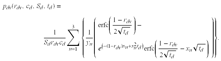
- With respect to the transient portion of equation (1) above, the model equation for the pressure transient is:

- where y n is one of:
- y 1 =x 1(x 1 −x 2)(x 1 −x 3) (10)
- y 2 =x 2(x 2 −x 1)(x 2 −x 3) (11)
- y 3 =x 3(x 3 −x 1)(x 3 −x 2) (12)
- and where x n are the three roots of the equation:

- Derivation of equation (9) is provided in the appendix of Society of Petroleum Engineers Paper No. SPE 64650, which is incorporated by reference herein as if reproduced in full below, and in Society of Petroleum Engineers Paper No. SPE 62919, which is also incorporated herein by reference as if reproduced in full below.
- In similar fashion to the source probe and its related equations described above, the analytic model of the preferred embodiment is also capable of modeling the time series pressure sensed at the
vertical probe 20. In the particular case where there is a dip angle between the formation and the well bore, and considering skin, the analytic model of the vertical probe pressure during a draw-down test is:
- where Q 0 is the flow rate defined above, μ is the formation fluid viscosity, kr is the horizontal permeability, λ is the ratio of the vertical to horizontal permeability as defined above, θ is the dip angle, and pd is the dimensionless transient pressure response expected for the vertical probe as a function of the dimensionless vertical probe radius rdv, the dimensionless compressibility constant cd, the dimensionless skin factor Sd and dimensionless time td, where the dimensionless td is given by the equation:

- where φ is the formation porosity, and c is the total compressibility, and where the dimensionless vertical probe radius r dv is given by:

- where r v is the probe spacing.
- Similar to the model equation of the source probe equation (14) above is logically divided into a static portion, contained in parenthesis, and a transient portion, contained in brackets. The transient portion of the analytic model representing the vertical probe response is given by:

- where r dv is dimensionless probe spacing, and where the remaining parameters are as defined above.
- By combining equations (1) and (14), the anisotropy for the particular formation is thus as follows:

- and if the dip angle is zero, this reduces to

- Applying the actual sensed pressure time series to the analytic models exemplified in equations (1) and (14) will not yield the desired formation parameters information in only one calculation. That is, the variables within these equations are manipulated to make the analytic model predicted pressure response match the actual formation test data thus yielding the parameters of interest. Preferably, fluid viscosity ju is supplied by an external source, such as by MWD tools, or preferably by a viscosity analysis tool or meter coupled to the
tool 10. An initial estimate as to the various parameters for the analytical model is made and the results predicted by the analytical model are compared to the actual time series. The parameters are accordingly adjusted, and the model run again using regression analysis techniques known to those of ordinary skill in the art. The regression analysis could take many hundreds or thousands of iterations. The regression analysis stops, in the preferred embodiments, when the modeled pressure response substantially matches the actual pressure response, within approximately five percent. The final state of the manipulated parameters when the regression analysis completes are the formation parameters determined by the model. - In embodiments having two probes, a
source probe 18 and avertical probe 20, the dip angle must be provided for there to be a solution to the equations. Obtaining dip angle prior to running the wireline formation testing of the preferred embodiment may be obtained by many known techniques, including measuring-while-drilling (MWD) devices capable of taking these measurements. Other parameters such as the viscosity of the formation fluid and compressibility of the formation fluid (which manifest itself as the storage effect) may be determined by other downhole tools, including the wireline formation tool itself prior to, during, or after the permeability test described herein. In yet another embodiment, only the source probe could be used, along with the analytical model of equation (1), and in so doing the spherical permeability, along with the skin, could be determined. - In the preferred embodiments, two probes and an externally supplied dip angle are used to determine the horizontal permeability and the permeability anisotropy. The analytic models may be manipulated, however, such that the determination as to permeability may consider only skin, or only dip angle. In the case of a permeability determination taking into consideration skin of the formation, but not dip angle, equation (1) above for the source probe would remain unchanged, but equation (14) modeling the vertical probe response reduces to:

- with P d as defined in equation (9) above.
- In the case of a permeability determination taking into dip angle but not skin, equation ( 1) becomes:

- where p d is given by:

- where β n is given substantially by:

- In this second case, taking into account dip angle but not skin, the equation for the vertical probe is the same as equation (14) above.
- Numerous variations and modifications will become apparent to those skilled in the art once the above disclosure is fully appreciated. While the preferred embodiment is a wireline formation tester, the system and methods described in this specification could be implemented in tool within a drill string. In an drill string embodiment, drilling ceases during tested, and solving the analytic models described above takes place on a microprocessor or microprocessors within the tool. The results may be stored for later retrieval, or the results or summaries of the results telemetered to the surface using known or after developed techniques. It is intended that the following claims be interpreted to embrace all such variations and modifications.
Claims (31)
1. A method of performing hydraulic permeability testing of anisotropic earth formations, the method comprising:
coupling a first probe to the earth formation;
coupling a second probe to the earth formation;
inducing a fluid flow from the formation into the first probe;
measuring a pressure response at the first probe caused by the fluid flow;
measuring a pressure response at the second probe caused by the fluid flow; and
determining the effect skin of the formation has on a measured hydraulic permeability of the formation, the determination based on the pressure responses measured at the first and second probes.
2. The method of performing permeability testing as defined in claim 1 wherein determining the effect skin of the formation has on the hydraulic permeability further comprises using regression analysis on an analytic model until a set of modeled pressure responses substantially matches the measured pressure responses at the first and second probes, where one of the manipulated parameters is indicative of the effect skin of the formation has on the measured hydraulic permeability.
3. The method of performing permeability testing as defined in claim 2 wherein manipulating parameters of an analytic model further comprises manipulating parameters of substantially the following equation:

where ΔPp is the modeled pressure response the first probe, Sd is a dimensionless skin constant, kf is the spherical permeability, μ is a formation fluid viscosity, Q0 is the rate of fluid flow from the formation into the first probe, τs is a geometric shape factor for the first probe, rp is the first probe radius, and pds is a predicted transient response given substantially by the equation:

where cd is a dimensionless compressibility factor of fluid in the earth formation, td is dimensionless time, yn is one of:
y 1 =x 1(x 1 −x 2)(x 1 −x 3) y 2 =x 2(x 2 −x 1)(x 2 x 3) y 3 =x 3(x 3 −x 1)(x 3 −x 2)
and where x1, x2 and x3 are roots of the following equation:

4. The method of performing permeability testing as defined in claim 3 wherein manipulating parameters of an analytic model further comprises manipulating substantially the following equation:

where ΔPZ is the modeled pressure response at the second probe, τv is a geometric shape factor for the second probe, rv is a physical spacing between first and second probe, kr is the horizontal permeability, rdv is a dimensionless spacing between the first and second probe and pd is a predicted transient response given substantially by the equation:

5. A hydraulic permeability tool, comprising:
a tool body;
a first probe coupled to the tool body, the first probe adapted to be fluidly coupled to a borehole wall, the first probe having a first pressure transducer coupled thereto;
a second probe coupled to the tool body and vertically displaced from the first probe, the second probe adapted to be fluidly coupled to the borehole wall, and the second probe having a second pressure transducer coupled thereto;
a pump coupled to the first probe;
a computer coupled to the first and second pressure probes, and wherein the computer is adapted to read pressures responses sensed at the first and second pressure transducers to determine hydraulic permeability anisotropy and skin of a formation taking into account a dip angle between the borehole and the formation.
6. The hydraulic permeability tool as defined in claim 5 wherein the computer is further adapted to implement regression analysis on an analytic model until a set of modeled pressure responses matches the pressure responses sensed at the first and second probes, and wherein parameters of the analytic model predict the formation hydraulic permeability and skin.
7. The hydraulic permeability tool as defined in claim 6 wherein the computer is further adapted to implement the regression analysis on the on the following equation:

where ΔPp is the modeled pressure reaction the first probe through which a draw-down test is performed, Sd is a dimensionless skin constant, kf is the spherical permeability, μ is a formation fluid viscosity, Q0 is the rate of fluid flow from the formation into the first probe, τs is a geometric shape factor for the first probe, rp is first probe radius, pds is a predicted transient response given substantially by the equation:

where cd is a dimensionless compressibility factor of fluid in the formation, td is dimensionless time, yn is one of:
y 1 =x 1(x 1 −x 2)(x 1 −x 3) y 2 =x 2(x 2 −x 1)(x 2 −x 3) y 3 =x 3(x 3 −x 1)(x 3 −x 2)
and where x1, x2 and x3 are roots of the following equation:

8. The hydraulic permeability tool as defined in claim 7 wherein the computer is further adapted to implement the regression analysis on the following equation:

where ΔPZ is the modeled pressure response at the second probe, τv is a geometric shape factor for the second probe, rv is a distance between the first probe and the second probe, kr is the horizontal permeability, λ is the hydraulic permeability anisotropy, θ is the angle of the formation relative to an axis of the borehole, rdv is a dimensionless distance between the first probe and the second probe and pd is a predicted transient response given substantially by the equation:

9. The hydraulic permeability tool as defined in claim 5 wherein the tool body further comprises a wireline logging tool body.
10. The hydraulic permeability tool as defined in claim 5 wherein the tool body further comprises a logging-while-drilling tool body.
11. The hydraulic permeability tool as defined in claim 5 further comprising a fluid viscosity meter coupled to the tool body, and wherein the computer uses a viscosity reading provided by the viscosity meter as part of the determination of the hydraulic permeability.
12. A method comprising:
performing a draw-down test on an anisotropic earth formation traversing a borehole;
detecting formation pressure reactions associated with the draw-down test at a first probe and a second probe;
determining hydraulic permeability anisotropy of the earth formation using the formation pressure reactions and taking into account a dip angle of the earth formation.
13. The method as defined in claim 12 wherein determining the hydraulic permeability anisotropy of the earth formation using the formation pressure reactions and taking into account the dip angle further comprises using regression analysis on an analytic model until a set of modeled pressure reactions substantially matches the formation pressure reactions at the first and second probes.
14. The method as defined in claim 13 wherein manipulating parameters of an analytic model further comprises manipulating parameters of substantially the following equation:

where ΔPp is a modeled pressure response the first probe, kf is a spherical permeability, μ is a formation fluid viscosity, Q0 is a rate of fluid flow from the formation into the first probe during the draw-down test, τs is a geometric shape factor for the first probe, rp is the first probe radius, and pd is a predicted transient response given substantially by the equation:

where cd is a dimensionless compressibility factor of fluid in the earth formation, td is dimensionless time, rd is equal to 1, β1 is given substantially by:

and where β2 is given substantially by:

15. The method as defined in claim 14 wherein manipulating parameters of an analytic model further comprises manipulating substantially the following equation:

where ΔPZ is the modeled pressure response at the second probe, τv is a geometric shape factor for the second probe, rv is radius correction factor for the second probe, kr is the horizontal permeability, rdv is a dimensionless spacing between the first and second probe and pdv is a predicted transient response given substantially by the equation:

where Yn is given by:

16. A logging tool, comprising:
a tool body adapted to be suspended in a borehole by way of a cable;
a source probe coupled to the tool body, the source probe adapted to be fluidly coupled to the borehole wall;
a pump coupled to the source probe, the pump adapted to displace fluid through the source probe while the source probe is coupled to the borehole wall;
a first pressure transducer coupled to the source probe, the first pressure transducer adapted to sense a pressure response of the formation caused by the displacing of fluid through the source probe; and
a computer coupled to the pump and first pressure transducer through the cable, wherein the computer selective controls the pump, and records the pressure response sensed by the first pressure transducer, and wherein the computer is adapted to determine spherical permeability and skin of the formation adjacent to the borehole wall based on the pressure response sensed.
17. The logging tool as defined in claim 16 wherein the computer is further adapted to perform regression analysis on an analytic model until a modeled pressure response matches the pressure response sensed, and wherein the parameters of the analytic model predict the spherical permeability and the skin.
18. The logging tool as defined in claim 17 wherein the computer is further adapted to implement the regression analysis on the following equation:

where ΔPp is the modeled pressure response, Sd is a dimensionless skin constant, kf is the spherical permeability, μ is a formation fluid viscosity, Q0 is the rate of displaced from the formation into the source probe, τs is a geometric shape factor for the source probe, rp is the source probe radius, pds is a predicted transient response given substantially by the equation:

where cd is a dimensionless compressibility factor of fluid in the formation, td is dimensionless time, yn is one of:
y 1 =x 1(x 1 −x 2)(x 1 −x 3) y 2 =x 2(x 2 −x 1)(x 2 −x 3) y 3 =x 3(x 3 −x 1)(x 3 −x 2)
and where x1, x2 and x3 are roots of the following equation:

19. The logging device as defined in claim 18 further comprising:
a vertically displaced probe coupled to the tool body vertically displaced from the source probe, the vertically displaced probe adapted to be fluidly coupled to the borehole wall;
a second pressure transducer coupled to the vertically displaced probe, the second pressure transducer adapted to sense a pressure response of the formation caused by the displacing of fluid through the source probe; and
wherein the computer is adapted to determine the vertical permeability of the formation based on the pressure sensed by the first and second pressure transducers.
20. The logging tool as defined in claim 19 wherein the computer is further adapted to implement regression analysis on an analytic model until a set of modeled pressure responses for the source and vertically displaced probes matches the pressure responses sensed by the first and second pressure transducers, and wherein parameters of the analytic model predict the formation vertical permeability.
21. The logging tool as defined in claim 20 wherein the computer is further adapted to implement regression analysis on the following equation:

where ΔPZ is the modeled pressure response at the vertically displaced probe, τv is a geometric shape factor for the vertically displaced probe, rv is a distance between the source probe and the vertically displaced probe, kr is the horizontal permeability, λ is the hydraulic permeability anisotropy, θ is the angle of the formation relative to an axis of the borehole, rdv is a dimensionless distance between the source probe and the vertically displaced probe and pd is a predicted transient response given substantially by the equation:
22. A method of determining hydraulic permeability of an anisotropic earth formation traversed by a borehole, the method comprising:
fluidly coupling a source probe to the earth formation;
fluidly coupling a vertically displaced probe to the earth formation;
measuring a pressure reaction at the source probe caused by pulling fluid from the formation into the source probe;
measuring a second pressure reaction at the vertically displaced probe caused by the pulling of fluid from the formation into the first probe;
determining the hydraulic permeability anisotropy of the earth formation with pressure reactions measured at the source and vertically displaced probes, where the determination compensates for damage to the formation near the borehole wall and the angle of the formation relative to an axis of the borehole.
23. The method as defined in claim 22 wherein determining hydraulic permeability anisotropy of the of the earth formation further comprises manipulating parameters of an analytic model until a set of modeled pressure reactions substantially matches the measured pressure reactions at the source and vertically displaces probes.
24. The method of performing permeability testing as defined in claim 23 wherein manipulating parameters of an analytic model further comprises manipulating parameters of substantially the following equation:

where ΔPp is the modeled pressure reaction the source probe, Sd is a dimensionless skin constant, kf is the spherical permeability, μ is a formation fluid viscosity, Q0 is the rate of fluid flow from the formation into the source probe, τs is a geometric shape factor for the source probe, rp is the source probe radius, pds is a predicted transient response given substantially by the equation:

where cd is a dimensionless compressibility factor of fluid in the earth formation, td is dimensionless time, yn is one of:
y 1 =x 1(x 1 −x 2)(x 1 −x 3) y 2 =x 2(x 2 −x 1)(x 2 −x 3) y 3 =x 3(x 3 −x 1)(x 3 −x 2)
and where x1, x2 and x3 are roots of the following equation:

25. The method of performing permeability testing as defined in claim 24 wherein manipulating parameters of an analytic model further comprises manipulating parameters of substantially the following equation:

where ΔPZ is the modeled pressure response at the vertically displaced probe, τv is a geometric shape factor for the vertically displaced probe, rv is a distance between the source probe and the vertically displaced probe, kr is the horizontal permeability, λ is the hydraulic permeability anisotropy, θ is the angle of the formation relative to an axis of the borehole, rdv is a dimensionless distance between the source probe and the vertically displaced probe and pd is a predicted transient response given substantially by the equation:

26. A method comprising:
performing a draw-down test on an anisotropic earth formation traversing a borehole;
detecting pressure responses at a source probe and a vertical probe caused by the draw-down test;
determining hydraulic permeability anisotropy of the of the earth formation using the pressure responses and compensating for damage to the earth formation along a borehole wall.
27. The method as defined in claim 26 wherein determining hydraulic permeability anisotropy further comprises calculating the hydraulic permeability anisotropy with substantially the following equation:

where λ is the anisotropy, kz is the vertical permeability, kr is the horizontal permeability, τs is a geometric shape factor for the source probe, rv is the radius of the vertical probe, τv is a geometric shape factor for the vertical probe, rs is the radius of the source probe, ΔPZ is a steady state pressure drop sensed at the vertical probe during the draw-down, ΔPs is a steady state pressure drop sensed at the source probe during the draw-down test, and where Sd is a dimensionless constant representing the damage to the earth formation along a borehole wall determined by recursively solving substantially the following equations until a predicted pressure response matches the detected response:

where ΔPp(t) is the predicted pressure response of the source probe, ΔPZ(t) is the predicted pressure response of the vertical probe, kf is the spherical permeability, Qo is a fluid flow rate during the draw-down test, rp is the radius of the source probe, μ is a formation fluid viscosity, rv is a physical spacing between the source and vertical probe, rdv is a dimensionless spacing between the source probe and vertical probe, pds is a predicted transient response given substantially by the equation:

where cd is a dimensionless compressibility factor of fluid in the earth formation, td is dimensionless time, yn is one of:
y 1 =x 1(x 1 −x 2)(x 1 −x 3) y 2 =x 2(x 2 −x 1)(x 2 −x 3) y 3 =x 3(x 3 −x 1)(x 3 −x 2)
where x1, x2 and x3 are roots of the following equation:

and where pd is given substantially by:

28. A method of performing a draw-down test on an anisotropic earth formation traversing a borehole, the method comprising:
detecting pressure responses at a source probe and a vertical probe, each probe fluidly coupled to the earth formation, the pressure responses caused by the draw-down test; and
determining hydraulic permeability anisotropy of the of the earth formation using the pressure responses and compensating for damage to the earth formation along a borehole wall and the dip angle of the formation.
29. The method as defined in claim 28 wherein determining hydraulic permeability anisotropy further comprises calculating the hydraulic permeability anisotropy with by solving substantially the following equation:

where λ is the anisotropy, kz is the vertical permeability, kr is the horizontal permeability, τs is a geometric shape factor for the source probe, rv is a distance between the source probe the vertical probe, τv is a geometric shape factor for the vertical probe, rs is a radius of the source probe, ΔPZ is a pressure drop sensed at the vertical probe during the draw-down test after all the transients have dissipated, ΔPs is a pressure drop sensed at the source probe during the draw-down test after all the transients have dissipated, θ is the dip angle, and where Sd is a dimensionless constant representing the damage to the earth formation along a borehole wall determined by recursively solving substantially the following equations until a predicted pressure response matches the detected pressure response:

where ΔPp(t) is the predicted pressure response of the source probe, ΔPZ(t) is the predicted pressure response of the vertical probe, kf is the spherical permeability, Qo is a fluid flow rate during the draw-down test, rp is the radius of the source probe, μ is a formation fluid viscosity, rdv is a dimensionless distance between the source probe and the vertical probe, pds is a predicted transient response given substantially by the equation:

where cd is a dimensionless compressibility factor of fluid in the earth formation, td is dimensionless time, yn is one of:
y 1 =x 1(x 1 −x 2)(x 1 −x 3) y 2 =x 2(x 2 −x 1)(x 2 −x 3) y 3 =x 3(x 3 −x 1)(x 3 −x 2)
where x1, x2 and x3 are roots of the following equation:

and where pd is given substantially by:

30. A method of performing a draw-down test on an anisotropic earth formation traversing a borehole, the method comprising:
coupling a source probe and a vertical probe to the earth formation;
detecting formation pressure reactions associated with the draw-down test at a source probe and a vertical probe;
determining hydraulic permeability anisotropy of the earth formation using the formation pressure reactions and taking into account a dip angle of the earth formation.
31. The method of performing a draw-down test on an anisotropic earth formation traversing a borehole as defined in claim 30 wherein determining hydraulic permeability anisotropy of the earth formation using the formation pressure reactions and taking into account a dip angle of the earth formation further comprises solving the substantially the following equation:

where λ is the anisotropy, θ is the dip angle and where:

A 2 =A 1 6 cos (θ) sin (θ) A 3=−108A 2+8+12A 1 3 sin (θ){square root}{square root over (3 cos (θ)(27A 2−4))}

where τs is a geometric shape factor for the source probe, rv is a distance between the source probe and the vertical probe, rv is a geometric shape factor for the vertical probe, rs is the equivalent source probe radius, ΔPZ is a steady state pressure drop sensed at the vertical probe during the draw-down, ΔPs is a steady state pressure drop sensed at the source probe during the draw-down test, pd(cd, td) is given substantially by:

where rd is 1, cd is a dimensionless compressibility factor of formation fluids, td is dimensionless time and βn is one of:

and where pd(rdv, cd, td) is given substantially by:

where rdv is a dimensionless distance between the source probe and the vertical probe.
Priority Applications (1)
| Application Number | Priority Date | Filing Date | Title |
|---|---|---|---|
| US10/254,310 US7059179B2 (en) | 2001-09-28 | 2002-09-25 | Multi-probe pressure transient analysis for determination of horizontal permeability, anisotropy and skin in an earth formation |
Applications Claiming Priority (2)
| Application Number | Priority Date | Filing Date | Title |
|---|---|---|---|
| US32590301P | 2001-09-28 | 2001-09-28 | |
| US10/254,310 US7059179B2 (en) | 2001-09-28 | 2002-09-25 | Multi-probe pressure transient analysis for determination of horizontal permeability, anisotropy and skin in an earth formation |
Publications (2)
| Publication Number | Publication Date |
|---|---|
| US20030094040A1 true US20030094040A1 (en) | 2003-05-22 |
| US7059179B2 US7059179B2 (en) | 2006-06-13 |
Family
ID=26943969
Family Applications (1)
| Application Number | Title | Priority Date | Filing Date |
|---|---|---|---|
| US10/254,310 Active 2024-05-28 US7059179B2 (en) | 2001-09-28 | 2002-09-25 | Multi-probe pressure transient analysis for determination of horizontal permeability, anisotropy and skin in an earth formation |
Country Status (1)
| Country | Link |
|---|---|
| US (1) | US7059179B2 (en) |
Cited By (26)
| Publication number | Priority date | Publication date | Assignee | Title |
|---|---|---|---|---|
| US20040026125A1 (en) * | 2001-07-20 | 2004-02-12 | Baker Hughes Incorporated | Formation testing apparatus and method for optimizing draw down |
| US20040045706A1 (en) * | 2002-09-09 | 2004-03-11 | Julian Pop | Method for measuring formation properties with a time-limited formation test |
| US20040160858A1 (en) * | 2003-02-18 | 2004-08-19 | Reinhart Ciglenec | Method and apparatus for determining downhole pressures during a drilling operation |
| US20040230378A1 (en) * | 2003-05-02 | 2004-11-18 | Halliburton Energy Services, Inc. | Determining gradients using a multi-probed formation tester |
| US20050030021A1 (en) * | 2003-05-02 | 2005-02-10 | Prammer Manfred G. | Systems and methods for NMR logging |
| US20050116709A1 (en) * | 2003-10-04 | 2005-06-02 | Proett Mark A. | System and methods for upscaling petrophysical data |
| US20060042372A1 (en) * | 2004-08-26 | 2006-03-02 | Baker Hughes Incorporated | Determination of correct horizontal and vertical permeabilities in a deviated well |
| US20060042371A1 (en) * | 2004-08-26 | 2006-03-02 | Baker Hughes Incorporated | Determining horizontal and vertical permeabilities by analyzing two pretests in a horizontal well |
| FR2876408A1 (en) * | 2004-08-31 | 2006-04-14 | Schlumberger Services Petrol | APPARATUS AND METHOD FOR EVALUATING UNDERGROUND FORMATIONS IN A WELLBORE |
| US20070241750A1 (en) * | 2003-10-03 | 2007-10-18 | Ridvan Akkurt | System and methods for T1-based logging |
| US20080115934A1 (en) * | 2006-11-20 | 2008-05-22 | Pettinato Miguel H | Multi-Zone Formation Evaluation Systems and Methods |
| US20090204329A1 (en) * | 2008-02-12 | 2009-08-13 | Precision Energy Services, Inc. | Simultaneous analysis of two data sets from a formation test |
| US20090204328A1 (en) * | 2008-02-12 | 2009-08-13 | Precision Energey Services, Inc. | Refined analytical model for formation parameter calculation |
| US7584761B1 (en) * | 2000-06-30 | 2009-09-08 | Lam Research Corporation | Wafer edge surface treatment with liquid meniscus |
| EP2120068A1 (en) * | 2008-05-16 | 2009-11-18 | Total S.A. | Method for estimating the physical parameters of a geological formation |
| WO2012096826A3 (en) * | 2011-01-10 | 2013-08-22 | Saudi Arabian Oil Company | Flow profile modeling for wells |
| WO2013191693A1 (en) * | 2012-06-21 | 2013-12-27 | Halliburton Energy Services, Inc. | Method and apparatus for formation tester data interpretation with diverse flow models |
| US20140250998A1 (en) * | 2013-03-11 | 2014-09-11 | Schlumberger Technology Corporation | Detection of permeability anisotropy in the horizontal plane |
| WO2014205347A1 (en) * | 2013-06-20 | 2014-12-24 | Schlumberger Canada Limited | Detection of permeability anisotropy in the horizontal plane with a formation testing tool |
| CN105626061A (en) * | 2016-03-11 | 2016-06-01 | 陕西多奇电子科技有限公司 | Underground borehole structure detecting instrument and method |
| CN105971594A (en) * | 2016-05-18 | 2016-09-28 | 北京航空航天大学 | Horizontal well specific retention measuring method based on minimum root-mean-square error |
| EP2943649A4 (en) * | 2013-01-11 | 2016-10-26 | Baker Hughes Inc | Apparatus and method for obtaining formation fluid samples utilizing a sample clean-up device |
| WO2018156142A1 (en) * | 2017-02-24 | 2018-08-30 | Halliburton Energy Services, Inc. | Wellbore skin effect calculation using temperature measurements |
| CN109490166A (en) * | 2018-11-06 | 2019-03-19 | 北京理工大学 | A kind of channel permeability rate of porous media random cross-sectional shape determines method |
| WO2020198186A1 (en) * | 2019-03-25 | 2020-10-01 | Saudi Arabian Oil Company | Removing fluid from rock formations in oil and gas applications |
| US20230096270A1 (en) * | 2020-02-10 | 2023-03-30 | Halliburton Energy Services, Inc. | Split flow probe for reactive reservoir sampling |
Families Citing this family (8)
| Publication number | Priority date | Publication date | Assignee | Title |
|---|---|---|---|---|
| US8078403B2 (en) * | 2007-11-21 | 2011-12-13 | Schlumberger Technology Corporation | Determining permeability using formation testing data |
| US8136395B2 (en) | 2007-12-31 | 2012-03-20 | Schlumberger Technology Corporation | Systems and methods for well data analysis |
| US20100050761A1 (en) * | 2008-08-26 | 2010-03-04 | SchlumbergerTechnology Corporation | Detecting gas compounds for downhole fluid analysis |
| US8904859B2 (en) * | 2008-08-26 | 2014-12-09 | Schlumberger Technology Corporation | Detecting gas compounds for downhole fluid analysis |
| WO2011040924A1 (en) * | 2009-10-01 | 2011-04-07 | Halliburton Energy Services, Inc. | Determining anisotropy with a formation tester in a deviated borehole |
| US9085965B2 (en) | 2011-07-22 | 2015-07-21 | Halliburton Energy Services, Inc. | Apparatus and method for improved fluid sampling |
| CN103277093B (en) | 2013-06-18 | 2016-01-27 | 中国海洋石油总公司 | A kind of method for testing strata and formation tester |
| US11230923B2 (en) | 2019-01-08 | 2022-01-25 | Mark A. Proett | Apparatus and method for determining properties of an earth formation with probes of differing shapes |
Citations (14)
| Publication number | Priority date | Publication date | Assignee | Title |
|---|---|---|---|---|
| US2747401A (en) * | 1952-05-13 | 1956-05-29 | Schlumberger Well Surv Corp | Methods and apparatus for determining hydraulic characteristics of formations traversed by a borehole |
| US4043192A (en) * | 1976-06-08 | 1977-08-23 | The United States Of America As Represented By The United States Energy Research And Development Administration | Apparatus for providing directional permeability measurements in subterranean earth formations |
| US4742459A (en) * | 1986-09-29 | 1988-05-03 | Schlumber Technology Corp. | Method and apparatus for determining hydraulic properties of formations surrounding a borehole |
| US4890487A (en) * | 1987-04-07 | 1990-01-02 | Schlumberger Technology Corporation | Method for determining horizontal and/or vertical permeability of a subsurface earth formation |
| US5230244A (en) * | 1990-06-28 | 1993-07-27 | Halliburton Logging Services, Inc. | Formation flush pump system for use in a wireline formation test tool |
| US5247830A (en) * | 1991-09-17 | 1993-09-28 | Schlumberger Technology Corporation | Method for determining hydraulic properties of formations surrounding a borehole |
| US5335542A (en) * | 1991-09-17 | 1994-08-09 | Schlumberger Technology Corporation | Integrated permeability measurement and resistivity imaging tool |
| US5602334A (en) * | 1994-06-17 | 1997-02-11 | Halliburton Company | Wireline formation testing for low permeability formations utilizing pressure transients |
| US5672819A (en) * | 1996-03-13 | 1997-09-30 | Halliburton Energy Services, Inc. | Formation evaluation using phase shift periodic pressure pulse testing |
| US5703286A (en) * | 1995-10-20 | 1997-12-30 | Halliburton Energy Services, Inc. | Method of formation testing |
| US5770798A (en) * | 1996-02-09 | 1998-06-23 | Western Atlas International, Inc. | Variable diameter probe for detecting formation damage |
| US6164126A (en) * | 1998-10-15 | 2000-12-26 | Schlumberger Technology Corporation | Earth formation pressure measurement with penetrating probe |
| US6585045B2 (en) * | 2000-08-15 | 2003-07-01 | Baker Hughes Incorporated | Formation testing while drilling apparatus with axially and spirally mounted ports |
| US6964301B2 (en) * | 2002-06-28 | 2005-11-15 | Schlumberger Technology Corporation | Method and apparatus for subsurface fluid sampling |
-
2002
- 2002-09-25 US US10/254,310 patent/US7059179B2/en active Active
Patent Citations (14)
| Publication number | Priority date | Publication date | Assignee | Title |
|---|---|---|---|---|
| US2747401A (en) * | 1952-05-13 | 1956-05-29 | Schlumberger Well Surv Corp | Methods and apparatus for determining hydraulic characteristics of formations traversed by a borehole |
| US4043192A (en) * | 1976-06-08 | 1977-08-23 | The United States Of America As Represented By The United States Energy Research And Development Administration | Apparatus for providing directional permeability measurements in subterranean earth formations |
| US4742459A (en) * | 1986-09-29 | 1988-05-03 | Schlumber Technology Corp. | Method and apparatus for determining hydraulic properties of formations surrounding a borehole |
| US4890487A (en) * | 1987-04-07 | 1990-01-02 | Schlumberger Technology Corporation | Method for determining horizontal and/or vertical permeability of a subsurface earth formation |
| US5230244A (en) * | 1990-06-28 | 1993-07-27 | Halliburton Logging Services, Inc. | Formation flush pump system for use in a wireline formation test tool |
| US5335542A (en) * | 1991-09-17 | 1994-08-09 | Schlumberger Technology Corporation | Integrated permeability measurement and resistivity imaging tool |
| US5247830A (en) * | 1991-09-17 | 1993-09-28 | Schlumberger Technology Corporation | Method for determining hydraulic properties of formations surrounding a borehole |
| US5602334A (en) * | 1994-06-17 | 1997-02-11 | Halliburton Company | Wireline formation testing for low permeability formations utilizing pressure transients |
| US5703286A (en) * | 1995-10-20 | 1997-12-30 | Halliburton Energy Services, Inc. | Method of formation testing |
| US5770798A (en) * | 1996-02-09 | 1998-06-23 | Western Atlas International, Inc. | Variable diameter probe for detecting formation damage |
| US5672819A (en) * | 1996-03-13 | 1997-09-30 | Halliburton Energy Services, Inc. | Formation evaluation using phase shift periodic pressure pulse testing |
| US6164126A (en) * | 1998-10-15 | 2000-12-26 | Schlumberger Technology Corporation | Earth formation pressure measurement with penetrating probe |
| US6585045B2 (en) * | 2000-08-15 | 2003-07-01 | Baker Hughes Incorporated | Formation testing while drilling apparatus with axially and spirally mounted ports |
| US6964301B2 (en) * | 2002-06-28 | 2005-11-15 | Schlumberger Technology Corporation | Method and apparatus for subsurface fluid sampling |
Cited By (63)
| Publication number | Priority date | Publication date | Assignee | Title |
|---|---|---|---|---|
| US7584761B1 (en) * | 2000-06-30 | 2009-09-08 | Lam Research Corporation | Wafer edge surface treatment with liquid meniscus |
| US7011155B2 (en) * | 2001-07-20 | 2006-03-14 | Baker Hughes Incorporated | Formation testing apparatus and method for optimizing draw down |
| US20040026125A1 (en) * | 2001-07-20 | 2004-02-12 | Baker Hughes Incorporated | Formation testing apparatus and method for optimizing draw down |
| US7117734B2 (en) | 2002-09-09 | 2006-10-10 | Schlumberger Technology Corporation | Method for measuring formation properties with a time-limited formation test |
| US20040045706A1 (en) * | 2002-09-09 | 2004-03-11 | Julian Pop | Method for measuring formation properties with a time-limited formation test |
| US20050087009A1 (en) * | 2002-09-09 | 2005-04-28 | Jean-Marc Follini | Method for measuring formation properties with a time-limited formation test |
| US20050098312A1 (en) * | 2002-09-09 | 2005-05-12 | Jean-Marc Follini | Method for measuring formation properties with a time-limited formation test |
| US7263880B2 (en) | 2002-09-09 | 2007-09-04 | Schlumberger Technology Corporation | Method for measuring formation properties with a time-limited formation test |
| US20050173113A1 (en) * | 2002-09-09 | 2005-08-11 | Jean-Marc Follini | Method for measuring formation properties with a time-limited formation test |
| US20050187715A1 (en) * | 2002-09-09 | 2005-08-25 | Jean-Marc Follini | Method for measuring formation properties with a time-limited formation test |
| US7024930B2 (en) | 2002-09-09 | 2006-04-11 | Schlumberger Technology Corporation | Method for measuring formation properties with a time-limited formation test |
| US20070175273A1 (en) * | 2002-09-09 | 2007-08-02 | Jean-Marc Follini | Method for measuring formation properties with a time-limited formation test |
| US7290443B2 (en) | 2002-09-09 | 2007-11-06 | Schlumberger Technology Corporation | Method for measuring formation properties with a time-limited formation test |
| US7036579B2 (en) | 2002-09-09 | 2006-05-02 | Schlumberger Technology Corporation | Method for measuring formation properties with a time-limited formation test |
| US7210344B2 (en) | 2002-09-09 | 2007-05-01 | Schlumberger Technology Corporation | Method for measuring formation properties with a time-limited formation test |
| US6986282B2 (en) * | 2003-02-18 | 2006-01-17 | Schlumberger Technology Corporation | Method and apparatus for determining downhole pressures during a drilling operation |
| US20040160858A1 (en) * | 2003-02-18 | 2004-08-19 | Reinhart Ciglenec | Method and apparatus for determining downhole pressures during a drilling operation |
| US7021405B2 (en) | 2003-05-02 | 2006-04-04 | Halliburton Energy Services, Inc. | Determining gradients using a multi-probed formation tester |
| US20090072825A1 (en) * | 2003-05-02 | 2009-03-19 | Prammer Manfred G | Systems and methods for deep-looking nmr logging |
| US20050030021A1 (en) * | 2003-05-02 | 2005-02-10 | Prammer Manfred G. | Systems and methods for NMR logging |
| US20040230378A1 (en) * | 2003-05-02 | 2004-11-18 | Halliburton Energy Services, Inc. | Determining gradients using a multi-probed formation tester |
| US7733086B2 (en) | 2003-05-02 | 2010-06-08 | Halliburton Energy Services, Inc. | Systems and methods for deep-looking NMR logging |
| US20070241750A1 (en) * | 2003-10-03 | 2007-10-18 | Ridvan Akkurt | System and methods for T1-based logging |
| US7755354B2 (en) | 2003-10-03 | 2010-07-13 | Halliburton Energy Services, Inc. | System and methods for T1-based logging |
| US7224162B2 (en) | 2003-10-04 | 2007-05-29 | Halliburton Energy Services Group, Inc. | System and methods for upscaling petrophysical data |
| US20050116709A1 (en) * | 2003-10-04 | 2005-06-02 | Proett Mark A. | System and methods for upscaling petrophysical data |
| US7448263B2 (en) | 2004-08-26 | 2008-11-11 | Baker Hughes Incorporated | Practical methods to estimate horizontal and vertical permeabilities |
| US20060042372A1 (en) * | 2004-08-26 | 2006-03-02 | Baker Hughes Incorporated | Determination of correct horizontal and vertical permeabilities in a deviated well |
| US20060042371A1 (en) * | 2004-08-26 | 2006-03-02 | Baker Hughes Incorporated | Determining horizontal and vertical permeabilities by analyzing two pretests in a horizontal well |
| US7231818B2 (en) | 2004-08-26 | 2007-06-19 | Baker Hughes Incorporated | Determining horizontal and vertical permeabilities by analyzing two pretests in a horizontal well |
| US7181960B2 (en) | 2004-08-26 | 2007-02-27 | Baker Hughes Incorporated | Determination of correct horizontal and vertical permeabilities in a deviated well |
| US20070157719A1 (en) * | 2004-08-26 | 2007-07-12 | Baker Hughes Incorporated | Practical Methods to Estimate Horizontal and Vertical Permeabilities |
| FR2876408A1 (en) * | 2004-08-31 | 2006-04-14 | Schlumberger Services Petrol | APPARATUS AND METHOD FOR EVALUATING UNDERGROUND FORMATIONS IN A WELLBORE |
| US9447664B2 (en) | 2006-11-20 | 2016-09-20 | Halliburton Energy Services, Inc. | Multi-zone formation evaluation systems and methods |
| US8132621B2 (en) | 2006-11-20 | 2012-03-13 | Halliburton Energy Services, Inc. | Multi-zone formation evaluation systems and methods |
| US20110132601A1 (en) * | 2006-11-20 | 2011-06-09 | Halliburton Energy Services, Inc. | Multi-zone formation evaluation systems and methods |
| US20080115934A1 (en) * | 2006-11-20 | 2008-05-22 | Pettinato Miguel H | Multi-Zone Formation Evaluation Systems and Methods |
| US20090204328A1 (en) * | 2008-02-12 | 2009-08-13 | Precision Energey Services, Inc. | Refined analytical model for formation parameter calculation |
| GB2458548A (en) * | 2008-02-12 | 2009-09-30 | Precision Energy Services Inc | Earth formation testing by regression analysis of induced flow pressure measurements using refined model assuming hemispherical induced flow. |
| GB2458547A (en) * | 2008-02-12 | 2009-09-30 | Precision Energy Services Inc | Earth formation testing by regression analysis of induced flow pressure measurements |
| US20090204329A1 (en) * | 2008-02-12 | 2009-08-13 | Precision Energy Services, Inc. | Simultaneous analysis of two data sets from a formation test |
| US8583378B2 (en) * | 2008-05-16 | 2013-11-12 | Total Sa | Method of estimating physical parameters of a geological formation |
| EP2120068A1 (en) * | 2008-05-16 | 2009-11-18 | Total S.A. | Method for estimating the physical parameters of a geological formation |
| CN101592584A (en) * | 2008-05-16 | 2009-12-02 | 道达尔公司 | A kind of method of estimating architectonic physical parameter |
| FR2931189A1 (en) * | 2008-05-16 | 2009-11-20 | Total Sa Sa | METHOD FOR ESTIMATING PHYSICAL PARAMETERS OF A GEOLOGICAL FORMATION |
| US20100121580A1 (en) * | 2008-05-16 | 2010-05-13 | Total Sa | Method of estimating physical parameters of a geological formation |
| WO2012096826A3 (en) * | 2011-01-10 | 2013-08-22 | Saudi Arabian Oil Company | Flow profile modeling for wells |
| EP3020915A1 (en) * | 2011-01-10 | 2016-05-18 | Saudi Arabian Oil Company | Flow profile modeling for wells |
| US10662763B2 (en) | 2011-01-10 | 2020-05-26 | Saudi Arabian Oil Company | Measuring transmissivity of wells from multiple logs |
| WO2013191693A1 (en) * | 2012-06-21 | 2013-12-27 | Halliburton Energy Services, Inc. | Method and apparatus for formation tester data interpretation with diverse flow models |
| US11156741B2 (en) | 2012-06-21 | 2021-10-26 | Halliburton Energy Services, Inc. | Method and apparatus for formation tester data interpretation with diverse flow models |
| EP2943649A4 (en) * | 2013-01-11 | 2016-10-26 | Baker Hughes Inc | Apparatus and method for obtaining formation fluid samples utilizing a sample clean-up device |
| US20140250998A1 (en) * | 2013-03-11 | 2014-09-11 | Schlumberger Technology Corporation | Detection of permeability anisotropy in the horizontal plane |
| US9353620B2 (en) * | 2013-03-11 | 2016-05-31 | Schlumberger Technology Corporation | Detection of permeability anisotropy in the horizontal plane |
| US9759059B2 (en) | 2013-06-20 | 2017-09-12 | Schlumberge Technology Corporation | Detection of permeability anisotropy in the horizontal plane with a formation testing tool |
| WO2014205347A1 (en) * | 2013-06-20 | 2014-12-24 | Schlumberger Canada Limited | Detection of permeability anisotropy in the horizontal plane with a formation testing tool |
| CN105626061A (en) * | 2016-03-11 | 2016-06-01 | 陕西多奇电子科技有限公司 | Underground borehole structure detecting instrument and method |
| CN105971594A (en) * | 2016-05-18 | 2016-09-28 | 北京航空航天大学 | Horizontal well specific retention measuring method based on minimum root-mean-square error |
| WO2018156142A1 (en) * | 2017-02-24 | 2018-08-30 | Halliburton Energy Services, Inc. | Wellbore skin effect calculation using temperature measurements |
| CN109490166A (en) * | 2018-11-06 | 2019-03-19 | 北京理工大学 | A kind of channel permeability rate of porous media random cross-sectional shape determines method |
| WO2020198186A1 (en) * | 2019-03-25 | 2020-10-01 | Saudi Arabian Oil Company | Removing fluid from rock formations in oil and gas applications |
| US11306584B2 (en) | 2019-03-25 | 2022-04-19 | Saudi Arabian Oil Company | Removing fluid from rock formations in oil and gas applications |
| US20230096270A1 (en) * | 2020-02-10 | 2023-03-30 | Halliburton Energy Services, Inc. | Split flow probe for reactive reservoir sampling |
Also Published As
| Publication number | Publication date |
|---|---|
| US7059179B2 (en) | 2006-06-13 |
Similar Documents
| Publication | Publication Date | Title |
|---|---|---|
| US7059179B2 (en) | Multi-probe pressure transient analysis for determination of horizontal permeability, anisotropy and skin in an earth formation | |
| US7011155B2 (en) | Formation testing apparatus and method for optimizing draw down | |
| US7032661B2 (en) | Method and apparatus for combined NMR and formation testing for assessing relative permeability with formation testing and nuclear magnetic resonance testing | |
| CN108713089B (en) | Estimating formation properties based on borehole fluid and drilling logs | |
| US6675892B2 (en) | Well testing using multiple pressure measurements | |
| US6904365B2 (en) | Methods and systems for determining formation properties and in-situ stresses | |
| EP1716314B1 (en) | Smooth draw-down for formation pressure testing | |
| US9341557B2 (en) | Method and system for permeability calculation using production logs for horizontal wells, using a downhole tool | |
| US5247830A (en) | Method for determining hydraulic properties of formations surrounding a borehole | |
| US10370965B2 (en) | Method for determining a permeability or mobility of a radial flow response of a reservoir | |
| US5672819A (en) | Formation evaluation using phase shift periodic pressure pulse testing | |
| US8132453B2 (en) | Method for analysis of pressure response in underground formations | |
| US7181960B2 (en) | Determination of correct horizontal and vertical permeabilities in a deviated well | |
| US11230923B2 (en) | Apparatus and method for determining properties of an earth formation with probes of differing shapes | |
| US7448262B2 (en) | Determination of correct horizontal and vertical permeabilities in a deviated well | |
| US20040111216A1 (en) | Method of determining properties relating to an underbalanced well | |
| US10358919B2 (en) | Reservoir fluid geodynamics system and method | |
| US7448263B2 (en) | Practical methods to estimate horizontal and vertical permeabilities | |
| US7021405B2 (en) | Determining gradients using a multi-probed formation tester | |
| Kuchuk et al. | Estimating permeability distribution from 3D interval pressure transient tests | |
| WO2021046419A1 (en) | Systems and methods for saturation logging of hydrocarbon wells | |
| US20230349286A1 (en) | Geologic formation characterization | |
| CA2424112C (en) | A method and apparatus for combined nmr and formation testing for assessing relative permeability with formation testing and nuclear magnetic resonance testing | |
| US20240060398A1 (en) | System and method for methane hydrate based production prediction |
Legal Events
| Date | Code | Title | Description |
|---|---|---|---|
| AS | Assignment |
Owner name: HALLIBURTON ENERGY SERVICES, INC., TEXAS Free format text: ASSIGNMENT OF ASSIGNORS INTEREST;ASSIGNORS:PROETT, MARK A.;CHIN, WILSON C.;REEL/FRAME:013332/0593 Effective date: 20020924 |
|
| FEPP | Fee payment procedure |
Free format text: PAYOR NUMBER ASSIGNED (ORIGINAL EVENT CODE: ASPN); ENTITY STATUS OF PATENT OWNER: LARGE ENTITY |
|
| STCF | Information on status: patent grant |
Free format text: PATENTED CASE |
|
| FPAY | Fee payment |
Year of fee payment: 4 |
|
| FPAY | Fee payment |
Year of fee payment: 8 |
|
| FPAY | Fee payment |
Year of fee payment: 12 |