US20030074335A1 - Method and system for determining state-of-health of a nickel-metal hydride battery using an intelligent system - Google Patents
Method and system for determining state-of-health of a nickel-metal hydride battery using an intelligent system Download PDFInfo
- Publication number
- US20030074335A1 US20030074335A1 US10/127,292 US12729202A US2003074335A1 US 20030074335 A1 US20030074335 A1 US 20030074335A1 US 12729202 A US12729202 A US 12729202A US 2003074335 A1 US2003074335 A1 US 2003074335A1
- Authority
- US
- United States
- Prior art keywords
- battery
- selected frequencies
- impedance
- frequency
- health
- Prior art date
- Legal status (The legal status is an assumption and is not a legal conclusion. Google has not performed a legal analysis and makes no representation as to the accuracy of the status listed.)
- Granted
Links
Images


Classifications
-
- G—PHYSICS
- G01—MEASURING; TESTING
- G01R—MEASURING ELECTRIC VARIABLES; MEASURING MAGNETIC VARIABLES
- G01R31/00—Arrangements for testing electric properties; Arrangements for locating electric faults; Arrangements for electrical testing characterised by what is being tested not provided for elsewhere
- G01R31/36—Arrangements for testing, measuring or monitoring the electrical condition of accumulators or electric batteries, e.g. capacity or state of charge [SoC]
- G01R31/378—Arrangements for testing, measuring or monitoring the electrical condition of accumulators or electric batteries, e.g. capacity or state of charge [SoC] specially adapted for the type of battery or accumulator
- G01R31/379—Arrangements for testing, measuring or monitoring the electrical condition of accumulators or electric batteries, e.g. capacity or state of charge [SoC] specially adapted for the type of battery or accumulator for lead-acid batteries
-
- G—PHYSICS
- G01—MEASURING; TESTING
- G01R—MEASURING ELECTRIC VARIABLES; MEASURING MAGNETIC VARIABLES
- G01R31/00—Arrangements for testing electric properties; Arrangements for locating electric faults; Arrangements for electrical testing characterised by what is being tested not provided for elsewhere
- G01R31/36—Arrangements for testing, measuring or monitoring the electrical condition of accumulators or electric batteries, e.g. capacity or state of charge [SoC]
- G01R31/367—Software therefor, e.g. for battery testing using modelling or look-up tables
-
- G—PHYSICS
- G01—MEASURING; TESTING
- G01R—MEASURING ELECTRIC VARIABLES; MEASURING MAGNETIC VARIABLES
- G01R31/00—Arrangements for testing electric properties; Arrangements for locating electric faults; Arrangements for electrical testing characterised by what is being tested not provided for elsewhere
- G01R31/36—Arrangements for testing, measuring or monitoring the electrical condition of accumulators or electric batteries, e.g. capacity or state of charge [SoC]
- G01R31/389—Measuring internal impedance, internal conductance or related variables
-
- G—PHYSICS
- G01—MEASURING; TESTING
- G01R—MEASURING ELECTRIC VARIABLES; MEASURING MAGNETIC VARIABLES
- G01R31/00—Arrangements for testing electric properties; Arrangements for locating electric faults; Arrangements for electrical testing characterised by what is being tested not provided for elsewhere
- G01R31/36—Arrangements for testing, measuring or monitoring the electrical condition of accumulators or electric batteries, e.g. capacity or state of charge [SoC]
- G01R31/392—Determining battery ageing or deterioration, e.g. state of health
-
- Y—GENERAL TAGGING OF NEW TECHNOLOGICAL DEVELOPMENTS; GENERAL TAGGING OF CROSS-SECTIONAL TECHNOLOGIES SPANNING OVER SEVERAL SECTIONS OF THE IPC; TECHNICAL SUBJECTS COVERED BY FORMER USPC CROSS-REFERENCE ART COLLECTIONS [XRACs] AND DIGESTS
- Y10—TECHNICAL SUBJECTS COVERED BY FORMER USPC
- Y10S—TECHNICAL SUBJECTS COVERED BY FORMER USPC CROSS-REFERENCE ART COLLECTIONS [XRACs] AND DIGESTS
- Y10S706/00—Data processing: artificial intelligence
- Y10S706/90—Fuzzy logic
-
- Y—GENERAL TAGGING OF NEW TECHNOLOGICAL DEVELOPMENTS; GENERAL TAGGING OF CROSS-SECTIONAL TECHNOLOGIES SPANNING OVER SEVERAL SECTIONS OF THE IPC; TECHNICAL SUBJECTS COVERED BY FORMER USPC CROSS-REFERENCE ART COLLECTIONS [XRACs] AND DIGESTS
- Y10—TECHNICAL SUBJECTS COVERED BY FORMER USPC
- Y10S—TECHNICAL SUBJECTS COVERED BY FORMER USPC CROSS-REFERENCE ART COLLECTIONS [XRACs] AND DIGESTS
- Y10S706/00—Data processing: artificial intelligence
- Y10S706/902—Application using ai with detail of the ai system
Definitions
- the present invention relates to determining the state-of-health (SOH) of an electrochemical device. More particularly, the present invention relates to determining the SOH of a nickel metal hydride batteries using an intelligent system, e.g. a fuzzy logic system.
- SOH state-of-health
- a method of and system for determining the state-of-health of a nickel-metal hydride battery connected to a load comprising: detecting at least one of a real and imaginary part of an impedance of the battery at each of a first set of selected frequencies, said first set of selected frequencies including at least one frequency and determining the state-of-health of the battery from a fuzzy system trained in a relationship between each said impedance and said state-of-health.
- FIG. 1 is a block diagram of method for determining state-of-health of a Nickel metal hydride battery in accordance with the present invention
- FIG. 2 is a block diagram of an additive fuzzy system for use in the present invention
- FIG. 3A is a schematic diagram of a circuit to measure battery impedance
- FIG. 3B is a schematic diagram of a circuit to measure the current and voltage delivered by the nickel metal hydride battery to the load;
- FIG. 4 is a block diagram of a fuzzy system for use in determining the state of health in the present invention
- FIG. 5 is a circuit block diagram for determining nickel metal hydride battery impedance in accordance with the present invention.
- FIG. 6 is a circuit block diagram for determining state-of-health of a nickel metal hydride battery in accordance with the present invention
- FIG. 7A, and 7 B are membership functions for the five input variables used in the fuzzy system to determine state of health of nickel metal hydride battery in accordance with present invention.
- System 10 comprises nickel metal hydride battery 12 , a load 17 , an interface circuit 14 comprising impedance measuring device 14 a and current-voltage measuring device 14 b , a cycle counter 15 , and a fuzzy system 16 .
- the nickel metal hydride battery comprises a series string of nickel metal hydride cells. Fuzzy system 16 is trained in the relationship between impedance (via impedance measuring device 14 a ) and the SOH of the nickel metal hydride battery 12 .
- the current draw of the load from the nickel metal hydride battery 12 and voltage across the battery are measured using the current/voltage measuring device 14 b .
- a cycle is defined by the complete discharge of the battery followed by a complete recharge of the battery.
- the cycle number represents the number of battery cycles that the battery has completed.
- the cycle number of the nickel metal hydride battery under specific load conditions achieved by loading the battery with a load 17 can be used along with the SOH to determine whether a battery is malfunctioning, i.e., whether the determined SOH is appropriate for the battery's age as indicated by the cycle number.
- the cycle number may also be used as a measure of a battery's longevity when used under specified conditions, e.g., with a specific load.
- the impedance measurements are provided to fuzzy system 16 as inputs, with the SOH being the output of fuzzy system 16 . If the SOH is poor, then the SOH and cycle number may then be useful to determine whether the battery is malfunctioning or whether it has merely reached the end of its life.
- a fuzzy system may alternatively be trained in directly determining whether a battery is malfunctioning or not based on inputs including the cycle number.
- the SOH of a nickel metal hydride battery is defined as the device's ability to perform a specified task. Although a nickel metal hydride battery may be at a high State-of-Charge (SOC), its health may be poor due to loss of electrolyte or otherwise. Although a fully discharged nickel metal hydride battery may be at a low SOC, due to depletion of the charged species of the electrodes or otherwise, it may well be in a full SOH, which would be realized subsequent to recharging the nickel metal hydride battery. Phenomena such as loss of electrolyte and depletion of charged species affect the nickel metal hydride battery's power delivery capability and its capacity. Therefore, the nickel metal hydride battery's State-of-Health is a function of its ability to deliver power required by a load and its capacity to meet those requirements.
- SOC State-of-Charge
- a preferred embodiment of the fuzzy system comprises an additive fuzzy system 18 with centroid defuzzification 20 .
- Additive fuzzy system 18 stores m fuzzy rules of the form, “if X is A j then Y is B j ”, and computes the output F(x) as the centroid of the summed and partially fired then-part fuzzy sets B′ j , see Fuzzy Engineering by Bart Kosko, Prentice Hall, 1997.
- w j is a weight of rule j
- a j i represents if-part set function (membership function of input i of rule j on input i),
- a j represents joint if-part set function (result of “a j 1 ‘and’ a j 2 . . . ‘and’ a j i ) that states the degree to which the input x belongs to the if-part fuzzy set a j ,
- B j represents then-part set function (membership function j on the output)
- V j is the finite positive volume (or area) of the then-part set B j .
- c j is the centroid of the then-part set B j .
- B′ j is the scaled then-part set (scaled output membership function j, result of a j (x)B j ), and
- B is the output set prior to defuzzification.
- additive fuzzy system 18 can be described in terms of a set of if-then rules:
- RULE 1 If X 1 is a 1 1 and X 2 is a 2 1 . . . and X n is a n 1 , then F(X) is B 1 ,
- RULE 2 If X 1 is a 1 2 and X 2 is a 2 2 . . . and X n is a n 2 , then F(X) is B 2 ,
- n is the number of inputs.
- a supervised gradient descent can learn or tune additive fuzzy system 18 given by EQUATION 1 by changing the rule weights w j , the then-part volumes V j , the then-part centroids c j , or the if-part set functions a j .
- Circuit 24 comprises nickel metal hydride battery 12 whose impedance is to be measured, an a.c. current generator 26 of variable frequency, and a d.c. variable voltage generator 28 .
- Nickel metal hydride battery 12 and generators 26 and 28 are connected in series in any order but in such a way that nickel metal hydride battery 12 and d.c. generator 28 have in common poles of the same sign, in this example positive poles.
- the no-load voltage of nickel metal hydride 12 is designated as E 0
- the effective current of a.c. generator 26 is designated as I
- the voltage of d.c. generator 28 is designated as E.
- Voltage E is chosen so as to be equal to E 0 to prevent nickel metal hydride battery 12 issuing a direct current.
- the current flowing in the loop made up of nickel metal hydride battery 12 and generators 26 and 28 has no direct component and its alternating component designated I determines the voltage drop V across the nickel metal hydride battery 12 .
- This impedance has a real or resistive part Z′ and an imaginary or reactive part Z′′.
- , is given by
- (Z′ 2 +Z′′ 2 ) 1/2 .
- the battery impedance is a function of the frequency f of the a.c. current.
- FIG. 3B a circuit 5 for measuring the current draw of a load 17 connected to the nickel metal hydride battery 12 and the voltage across the nickel metal hydride battery 12 is shown.
- a voltmeter 6 is placed across the terminals of a nickel metal hydride battery 12 such that the positive lead of the voltmeter is connected to the positive terminal of said nickel metal hydride battery and the negative lead of the voltmeter is connected to the negative terminal of said nickel metal hydride battery.
- An ammeter 7 is used to measure the current from said nickel metal hydride battery to the load 17 .
- the ammeter 7 is connected in series between said nickel metal hydride battery 12 and the load 17 such that the current must flow from nickel metal hydride battery 12 through the ammeter 7 to pass into the load.
- fuzzy system 16 is trained in the relationship between certain impedance characteristics (e.g., real part, imaginary part, magnitude, and/or phase angle) at selected frequencies and the SOH of the nickel metal hydride battery. Specifically, the fuzzy system learns the underlying function F that relates the real and imaginary parts of the impedance at a first frequency f1, the real and imaginary parts of the impedance at a second frequency f2, and the real part of the impedance at a third frequency f3 to the state-of-health.
- the frequency f1 may be between about 10 Hz and about 30 Hz, is preferably between about 10 Hz and about 20 Hz, and in the example shown is 10 Hz.
- the frequency f2 may be between about 100 Hz and about 500 Hz, is preferably between about 200 Hz and about 500 Hz, and in the example shown is 251 Hz.
- the frequency f3 may be between 400 Hz and 10 kHz, is preferably between about 2 kHz and 10 kHz, and in the example shown is 3,981 Hz.
- the optimal frequencies for measuring impedance may vary from one type of nickel metal hydride battery to another, and can be determined empirically by mapping the impedances of a nickel metal hydride battery in various known conditions over a range of frequencies and selecting the frequency or frequencies at which the real and/or imaginary parts of the impedance varies the most.
- Circuit 30 for measuring impedance of nickel metal hydride battery 12 at three frequencies is generally shown.
- Circuit 30 comprises nickel metal hydride battery 12 whose impedance is to be measured and an a.c. signal generator 32 .
- Circuit 30 allows the determination of the impedance at different frequencies and may be set up to measure the impedance at the single frequency of interest. Instruments that can be used to perform the impedance measurements are commercially available. For example, the Solartron 1260 Impedance/Gain-Phase Analyzer available from Solartron, Inc., Houston, Tex., is suitable for this purpose.
- a circuit such as that shown in FIG. 6 may be used to determine nickel metal hydride battery SOH once the impedances are known.
- the impedance values at the three frequencies from circuit 30 are fed into a microcontroller 34 (e.g. Motorola MC 68HC11/12) either as analog or digital signals, wherein analog signals would be fed into the A/D converters on microcontroller 34 where they would be converted to digital signals.
- a microcontroller 34 e.g. Motorola MC 68HC11/12
- is stored in a first memory location
- the phase angle of the impedance at 10 Hz, ⁇ 1 is stored in a second memory location
- is stored in a third memory location
- the phase angle of the impedance at 251 Hz, ⁇ 2 is stored in a fourth memory location
- is stored in a fifth memory location
- the cycle number is stored at a seventh memory location.
- cos ⁇ and Z′′
- a fuzzy system implementation for determining the SOH of a series string of three Sanyo 2.7 Ah nickel metal hydride cells.
- the nickel metal hydride batteries are charged at a 0.9 A constant current for a period of 4 hours followed by a discharge at a constant current of 1.33A to a 3.0V cutoff voltage.
- This embodiment estimates the available capacity available from said nickel metal hydride battery at various cycles between the 109 th cycle and the 138 th cycle.
- a complete cycle is considered to be the complete charging of the battery followed by a complete discharge of the battery, the charging parameters and discharging parameters being as described in the previous sentence.
- a 5-input 1-output fuzzy logic model is used to estimate the available full-charge capacity of the nickel metal hydride battery. This is then combined with the cycle number datum to estimate the SOH of the nickel metal hydride battery.
- the five input variables to the fuzzy logic model are: 1) the real part of the impedance at 10 Hz, 2) the real part of the impedance at 3981 Hz, 3) the real part of the impedance at 251 Hz, 4) the imaginary part of the impedance at 10 Hz, and 5) the imaginary part of the impedance at 251 Hz.
- the output of the fuzzy logic model is the available full charge capacity of the battery.
- the input membership functions for the model are shown in FIG. 7 and the rule set is given in Table 1.
Abstract
Description
- This application is a Continuation-In-Part of U.S. patent application Ser. No. 09/041,501, filed Mar. 12, 1998, which is wholly incorporated herein by reference, and which claims the benefit of U.S. provisional patent application Serial No. 60/004,476 filed Mar. 12, 1997 and U.S. provisional patent application Serial No. 60/051,165 filed Jun. 27, 1997.
- [0002] This invention was made with Government support under contract USZA22-97-P-0010 awarded by the U.S. Department of Defense. The Government has certain rights in the invention.
- The present invention relates to determining the state-of-health (SOH) of an electrochemical device. More particularly, the present invention relates to determining the SOH of a nickel metal hydride batteries using an intelligent system, e.g. a fuzzy logic system.
- The SOH of a battery, fuel cell, or other electrochemical device has been interpreted in different ways by scientists/engineers in the field. In the case of valve regulated lead acid (VRLA) batteries used by utility companies for providing emergency backup power, SOH is interpreted to mean that a battery is close to the end of its cycle life and needs replacement. Several papers including Feder and Hlavac 1994 INTELEC Conf. Proc. pp. 282-291 (1994) and Hawkins and Hand 1996 INTELEC Conf. Proc. pp. 640-645 (1996) demonstrate that the increase in impedance of aging VRLA batteries can be used to indicate the SOH of the battery.
- Another interpretation of battery SOH is the capability of a battery to meet its load demand. This is also referred to as “battery condition” by others in the field. To obtain the SOH of a battery in the terms defined, both the available charge capacity of the battery and the maximum power available from the battery are required. Several approaches have been used to determine the condition of a battery. In U.S. Pat. No. 5,365,453 is described a method in which a ratio of a change in battery voltage to a change in load is used to predict impending battery failure in battery powered electronic devices. Similar methods in which the battery response to and recovery from the application of a load is used to determine the SOH of batteries are reported in U.S. Pat. Nos. 4,080,560 and 5,159,272. While these load profiling approaches work reasonably well for batteries integrated into a system, they are not necessarily accurate or reliable ways of determining the SOH of batteries outside a system.
- The above-discussed and other drawbacks and deficiencies of the prior art are overcome or alleviated by a method of and system for determining the state-of-health of a nickel-metal hydride battery connected to a load, the method comprising: detecting at least one of a real and imaginary part of an impedance of the battery at each of a first set of selected frequencies, said first set of selected frequencies including at least one frequency and determining the state-of-health of the battery from a fuzzy system trained in a relationship between each said impedance and said state-of-health.
- The above-discussed and other features and advantages of the present invention will be appreciated and understood by those skilled in the art from the following detailed description and drawings.
- Referring now to the drawings wherein like elements are numbered alike in the several FIGURES:
- FIG. 1 is a block diagram of method for determining state-of-health of a Nickel metal hydride battery in accordance with the present invention;
- FIG. 2 is a block diagram of an additive fuzzy system for use in the present invention;
- FIG. 3A is a schematic diagram of a circuit to measure battery impedance;
- FIG. 3B is a schematic diagram of a circuit to measure the current and voltage delivered by the nickel metal hydride battery to the load;
- FIG. 4 is a block diagram of a fuzzy system for use in determining the state of health in the present invention;
- FIG. 5 is a circuit block diagram for determining nickel metal hydride battery impedance in accordance with the present invention;
- FIG. 6 is a circuit block diagram for determining state-of-health of a nickel metal hydride battery in accordance with the present invention;
- FIG. 7A, and 7B are membership functions for the five input variables used in the fuzzy system to determine state of health of nickel metal hydride battery in accordance with present invention.
- Referring to FIG. 1 a system for determining State-of-Health (SOH) in accordance with present invention is generally shown at 10.
System 10 comprises nickelmetal hydride battery 12, aload 17, aninterface circuit 14 comprisingimpedance measuring device 14 a and current-voltage measuring device 14 b, acycle counter 15, and afuzzy system 16. The nickel metal hydride battery comprises a series string of nickel metal hydride cells.Fuzzy system 16 is trained in the relationship between impedance (viaimpedance measuring device 14 a) and the SOH of the nickelmetal hydride battery 12. - The current draw of the load from the nickel
metal hydride battery 12 and voltage across the battery are measured using the current/voltage measuring device 14 b. A cycle is defined by the complete discharge of the battery followed by a complete recharge of the battery. The cycle number represents the number of battery cycles that the battery has completed. The cycle number of the nickel metal hydride battery under specific load conditions achieved by loading the battery with aload 17 can be used along with the SOH to determine whether a battery is malfunctioning, i.e., whether the determined SOH is appropriate for the battery's age as indicated by the cycle number. The cycle number may also be used as a measure of a battery's longevity when used under specified conditions, e.g., with a specific load. Thus, the impedance measurements are provided tofuzzy system 16 as inputs, with the SOH being the output offuzzy system 16. If the SOH is poor, then the SOH and cycle number may then be useful to determine whether the battery is malfunctioning or whether it has merely reached the end of its life. A fuzzy system may alternatively be trained in directly determining whether a battery is malfunctioning or not based on inputs including the cycle number. - The SOH of a nickel metal hydride battery is defined as the device's ability to perform a specified task. Although a nickel metal hydride battery may be at a high State-of-Charge (SOC), its health may be poor due to loss of electrolyte or otherwise. Although a fully discharged nickel metal hydride battery may be at a low SOC, due to depletion of the charged species of the electrodes or otherwise, it may well be in a full SOH, which would be realized subsequent to recharging the nickel metal hydride battery. Phenomena such as loss of electrolyte and depletion of charged species affect the nickel metal hydride battery's power delivery capability and its capacity. Therefore, the nickel metal hydride battery's State-of-Health is a function of its ability to deliver power required by a load and its capacity to meet those requirements.
- Referring to FIG. 2, a preferred embodiment of the fuzzy system comprises an additive
fuzzy system 18 withcentroid defuzzification 20. Additivefuzzy system 18 stores m fuzzy rules of the form, “if X is Aj then Y is Bj”, and computes the output F(x) as the centroid of the summed and partially fired then-part fuzzy sets B′j, see Fuzzy Engineering by Bart Kosko, Prentice Hall, 1997.Equation 1 expresses mathematically additivefuzzy system 18 as: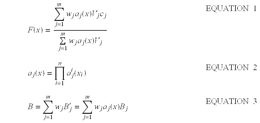
- where:
- w j is a weight of rule j,
- a j i represents if-part set function (membership function of input i of rule j on input i),
- a j represents joint if-part set function (result of “aj 1 ‘and’ aj 2 . . . ‘and’ aj i) that states the degree to which the input x belongs to the if-part fuzzy set aj,
- B j represents then-part set function (membership function j on the output),
- V j is the finite positive volume (or area) of the then-part set Bj,
- c j is the centroid of the then-part set Bj,
- B′ j is the scaled then-part set (scaled output membership function j, result of aj(x)Bj), and
- B is the output set prior to defuzzification.
- In linguistic terms, additive
fuzzy system 18 can be described in terms of a set of if-then rules: - RULE 1: If X 1 is a1 1 and X2 is a2 1 . . . and Xn is an 1, then F(X) is B1,
- RULE 2: If X 1 is a1 2 and X2 is a2 2 . . . and Xn is an 2, then F(X) is B2,
- RULE m: If X 1 is a1 m and X2 is a2 m . . . and Xn is an m, then F(X) is Bm,
- where m is the number of rules and n is the number of inputs.
- The linguistic description and the mathematical description of additive
fuzzy system 18 are equivalent. They are merely different views of the same fuzzy system. Both approaches map a given input X to a given output F(X) by a process known as fuzzy inference. The following example demonstrates the fuzzy inference process. First, fuzzify the inputs by taking the inputs and determine the degree to which they belong to each of the appropriate input fuzzy sets via membership functions. Mathematically expressed as: “a1 1(X1), a1 2(X2) . . . a1 m(Xm)”. Linguistically expressed as: “If X1=a1 1, If X2=a1 2, . . . , If Xm=a1 m”. Second, apply a fuzzy operator by combining if-part sets of a given rule to obtain one number that represents the result of the antecedent for that rule. Mathematically expressed as EQUATION 2 hereinabove. Linguistically expresses as: “a1 1 ‘and’ a1 2 ‘and’ a1 m” where ‘and’ is the T-norm product. Third, apply an implication method by shaping the consequent (or output fuzzy set) based on the result of the antecedent for that rule. Mathematically expressed as: “B1=a1(X)B1”. Linguistically expressed as: “If a1(X), then B1”. Fourth, aggregate all outputs by combining the consequent of each rule to form one output fuzzy set. Mathematically expressed asEQUATION 3 hereinabove. Fifth, defuzzify by mapping the output fuzzy set to a crisp number. Mathematically expressed as “F(x)=centroid(B)=EQUATION 1”. In general see Fuzzy Logic Toolbox, for use with MATLAB, The Mathworks, Inc. by Jang and Gulley. - By way of example, a supervised gradient descent can learn or tune additive
fuzzy system 18 given byEQUATION 1 by changing the rule weights wj, the then-part volumes Vj, the then-part centroids cj, or the if-part set functions aj. - Referring to FIG. 3A, a
circuit 24 for measuring nickel metal hydride battery impedance is shown.Circuit 24 comprises nickelmetal hydride battery 12 whose impedance is to be measured, an a.c.current generator 26 of variable frequency, and a d.c.variable voltage generator 28. Nickelmetal hydride battery 12 andgenerators metal hydride battery 12 and d.c.generator 28 have in common poles of the same sign, in this example positive poles. The no-load voltage ofnickel metal hydride 12 is designated as E0, the effective current of a.c.generator 26 is designated as I and the voltage of d.c.generator 28 is designated as E. Voltage E is chosen so as to be equal to E0 to prevent nickelmetal hydride battery 12 issuing a direct current. In this way, the current flowing in the loop made up of nickelmetal hydride battery 12 andgenerators metal hydride battery 12. Variables V and I are complex numbers and their ratio V/I=Z=Z′+jZ″ defines the internal complex impedance of nickelmetal hydride battery 12. This impedance has a real or resistive part Z′ and an imaginary or reactive part Z″. The magnitude of this impedance, |Z|, is given by |Z|=(Z′2+Z″2)1/2. The phase angle of the impedance, θ, is given by θ=tan−1(Z″/Z′). The battery impedance is a function of the frequency f of the a.c. current. - Referring to FIG. 3B, a
circuit 5 for measuring the current draw of aload 17 connected to the nickelmetal hydride battery 12 and the voltage across the nickelmetal hydride battery 12 is shown. Avoltmeter 6 is placed across the terminals of a nickelmetal hydride battery 12 such that the positive lead of the voltmeter is connected to the positive terminal of said nickel metal hydride battery and the negative lead of the voltmeter is connected to the negative terminal of said nickel metal hydride battery. Anammeter 7 is used to measure the current from said nickel metal hydride battery to theload 17. Theammeter 7 is connected in series between said nickelmetal hydride battery 12 and theload 17 such that the current must flow from nickelmetal hydride battery 12 through theammeter 7 to pass into the load. - Referring now to FIG. 4,
fuzzy system 16 is trained in the relationship between certain impedance characteristics (e.g., real part, imaginary part, magnitude, and/or phase angle) at selected frequencies and the SOH of the nickel metal hydride battery. Specifically, the fuzzy system learns the underlying function F that relates the real and imaginary parts of the impedance at a first frequency f1, the real and imaginary parts of the impedance at a second frequency f2, and the real part of the impedance at a third frequency f3 to the state-of-health. The frequency f1 may be between about 10 Hz and about 30 Hz, is preferably between about 10 Hz and about 20 Hz, and in the example shown is 10 Hz. The frequency f2 may be between about 100 Hz and about 500 Hz, is preferably between about 200 Hz and about 500 Hz, and in the example shown is 251 Hz. The frequency f3 may be between 400 Hz and 10 kHz, is preferably between about 2 kHz and 10 kHz, and in the example shown is 3,981 Hz. - While specific selected frequencies are listed herein and are known to be effective, it is understood that real and/or imaginary parts of impedance at other various frequencies and/or fewer different frequencies may also be effective in obtaining a valid result. Furthermore, the optimal frequencies for measuring impedance may vary from one type of nickel metal hydride battery to another, and can be determined empirically by mapping the impedances of a nickel metal hydride battery in various known conditions over a range of frequencies and selecting the frequency or frequencies at which the real and/or imaginary parts of the impedance varies the most.
- Referring to FIG. 5, a
circuit 30 for measuring impedance of nickelmetal hydride battery 12 at three frequencies is generally shown.Circuit 30 comprises nickelmetal hydride battery 12 whose impedance is to be measured and an a.c.signal generator 32. A small amplitude, perturbing sinusoidal signal, x(t)=X0 sin(ωt), is applied to nickelmetal hydride battery 12. The response of the nickelmetal hydride battery 12 to this perturbing signal is S(t)=X0K(ω)sin(ω[t+φ(ω)]) and is correlated with two reference signals, one in phase with x(t) and the other 90° out of phase with x(t), e.g. sin(ωt) and cos(ωt), in order to calculate:
- This allows the elimination of higher order harmonics than the fundamental and with an appropriate selection of frequency window and multiple measurements, noise rejection can be very high. In the limit as
- T→∞,→K(ω)cos φ(ω),ℑ→K(ω)sin φ(ω),

- where K(ω) represents the amplitude of the impedance at a frequency ω/2π and φ(ω) represents the phase of the impedance at frequency ω/2π.
Circuit 30 allows the determination of the impedance at different frequencies and may be set up to measure the impedance at the single frequency of interest. Instruments that can be used to perform the impedance measurements are commercially available. For example, the Solartron 1260 Impedance/Gain-Phase Analyzer available from Solartron, Inc., Houston, Tex., is suitable for this purpose. - A circuit such as that shown in FIG. 6 may be used to determine nickel metal hydride battery SOH once the impedances are known. The impedance values at the three frequencies from
circuit 30 are fed into a microcontroller 34 (e.g. Motorola MC 68HC11/12) either as analog or digital signals, wherein analog signals would be fed into the A/D converters onmicrocontroller 34 where they would be converted to digital signals. The magnitude of the impedance at 10 Hz, |Z1|, is stored in a first memory location, the phase angle of the impedance at 10 Hz, θ1, is stored in a second memory location, the magnitude of the impedance at 251 Hz, |Z2|, is stored in a third memory location, and the phase angle of the impedance at 251 Hz, θ2, is stored in a fourth memory location, the magnitude of the impedance at 3981 Hz, |Z3|, is stored in a fifth memory location, and the phase angle at 3981 Hz is stored at a sixth memory location, and the cycle number is stored at a seventh memory location. The variables Z and θ are used to compute the real and imaginary parts of the impedance at 10 Hz and at 251 Hz and the real part of the impedance at 3981 Hz using the equations Z′=|Z| cos θ and Z″=|Z| sin θ. These computations are performed within the microcontroller and the resulting real component of the impedance at 10 Hz, Z1′, and the imaginary component of the impedance at 10 Hz, Z1″, and the real component of the impedance at 251 Hz, Z2′, the imaginary component of the impedance at 251 Hz, Z2″, and the real component of the impedance at 3981 Hz are stored in an eighth, ninth, tenth, eleventh, and twelfth memory locations respectively. The variables in the 7th through 12th memory locations serve as the input variables to the fuzzy system to determine the SOH of the nickelmetal hydride battery 12. The output of this fuzzy system, the SOH of nickelmetal hydride battery 12, is stored in a thirteenth memory location. The battery SOH is then output to a display driver 36 and interfaced to aliquid crystal display 38. - In one embodiment of this method, a fuzzy system implementation for determining the SOH of a series string of three Sanyo 2.7 Ah nickel metal hydride cells. The nickel metal hydride batteries are charged at a 0.9 A constant current for a period of 4 hours followed by a discharge at a constant current of 1.33A to a 3.0V cutoff voltage. This embodiment estimates the available capacity available from said nickel metal hydride battery at various cycles between the 109 th cycle and the 138th cycle. A complete cycle is considered to be the complete charging of the battery followed by a complete discharge of the battery, the charging parameters and discharging parameters being as described in the previous sentence.
- A 5-input 1-output fuzzy logic model is used to estimate the available full-charge capacity of the nickel metal hydride battery. This is then combined with the cycle number datum to estimate the SOH of the nickel metal hydride battery. The five input variables to the fuzzy logic model are: 1) the real part of the impedance at 10 Hz, 2) the real part of the impedance at 3981 Hz, 3) the real part of the impedance at 251 Hz, 4) the imaginary part of the impedance at 10 Hz, and 5) the imaginary part of the impedance at 251 Hz. The output of the fuzzy logic model is the available full charge capacity of the battery. The input membership functions for the model are shown in FIG. 7 and the rule set is given in Table 1.
TABLE 1 Fuzzy Logic Model Rules for Nickel Metal Hydride Battery Capacity Estimation. If (in1 is in1mf1) and (in2 is in2mf1) and (in3 and in3mf1) and (in4 is in4mf1) and (in5 is in5mf1) then (out1 is out1mf1) (1) If (in1 is in1mf2) and (in2 is in2mf2) and (in3 and in3mf2) and (in4 is in4mf2) and (in5 is in5mf2) then (out1 is out1mf2) If (in1 is in1mf3) and (in2 is in2mf3) and (in3 and in3mf3) and (in4 is in4mf3) and (in5 is in5mf3) then (out1 is out1mf3) If (in1 is in1mf4) and (in2 is in2mf4) and (in3 and in3mf4) and (in4 is in4mf4) and (in5 is in5mf4) then (out1 is out1mf4) If (in1 is in1mf5) and (in2 is in2mf5) and (in3 and in3mf5) and (in4 is in4mf5) and (in5 is in5mf5) then (out1 is out1mf5) If (in1 is in1mf6) and (in2 is in2mf6) and (in3 and in3mf6) and (in4 is in4mf6) and (in5 is in5mf6) then (out1 is out1mf6) If (in1 is in1mf7) and (in2 is in2mf7) and (in3 and in3mf7) and (in4 is in4mf7) and (in5 is in5mf7) then (out1 is out1mf7) If (in1 is in1mf8) and (in2 is in2mf8) and (in3 and in3mf8) and (in4 is in4mf8) and (in5 is in5mf8) then (out1 is out1mf8) If (in1 is in1mf9) and (in2 is in2mf9) and (in3 and in3mf9) and (in4 is in4mf9) and (in5 is in5mf9) then (out1 is out1mf9) If (in1 is in1mf10) and (in2 is in2mf10) and (in3 and in3mf10) and (in4 is in4mf10) and (in5 is in5mf10) then (out1 is out1mf10) If (in1 is in1mf11) and (in2 is in2mf11) and (in3 and in3mf11) and (in4 is in4mf11) and (in5 is in5mf11) then (out1 is out1mf11) If (in1 is in1mf12) and (in2 is in2mf12) and (in3 and in3mf12) and (in4 is in4mf12) and (in5 is in5mf12) then (out1 is out1mf12) If (in1 is in1mf13) and (in2 is in2mf13) and (in3 and in3mf13) and (in4 is in4mf13) and (in5 is in5mf13) then (out1 is out1mf13) If (in1 is in1mf14) and (in2 is in2mf14) and (in3 and in3mf14) and (in4 is in4mf14) and (in5 is in5mf14) then (out1 is out1mf14) If (in1 is in1mf15) and (in2 is in2mf15) and (in3 and in3mf15) and (in4 is in4mf15) and (in5 is in5mf15) then (out1 is out1mf15) - While preferred embodiments have been shown and described, various modifications and substitutions may be made thereto without departing from the spirit and scope of the invention. Terms such as “first” and “second” as used herein are not intended to imply an order of importance or location, but merely to distinguish between one element and another of like kind. It is to be understood that the invention has been described by way of illustration only, and such illustrations and embodiments as have been disclosed herein are not to be construed as limiting to the claims.
Claims (20)
Priority Applications (1)
| Application Number | Priority Date | Filing Date | Title |
|---|---|---|---|
| US10/127,292 US7051008B2 (en) | 1997-03-12 | 2002-04-22 | Method and system for determining state-of-health of a nickel-metal hydride battery using an intelligent system |
Applications Claiming Priority (4)
| Application Number | Priority Date | Filing Date | Title |
|---|---|---|---|
| US4047697P | 1997-03-12 | 1997-03-12 | |
| US5116597P | 1997-06-27 | 1997-06-27 | |
| US09/041,501 US6456988B1 (en) | 1997-03-12 | 1998-03-12 | Method for determining state-of-health using an intelligent system |
| US10/127,292 US7051008B2 (en) | 1997-03-12 | 2002-04-22 | Method and system for determining state-of-health of a nickel-metal hydride battery using an intelligent system |
Related Parent Applications (2)
| Application Number | Title | Priority Date | Filing Date |
|---|---|---|---|
| US09/041,501 Continuation-In-Part US6456988B1 (en) | 1997-03-12 | 1998-03-12 | Method for determining state-of-health using an intelligent system |
| US09/041,501 Continuation US6456988B1 (en) | 1997-03-12 | 1998-03-12 | Method for determining state-of-health using an intelligent system |
Publications (2)
| Publication Number | Publication Date |
|---|---|
| US20030074335A1 true US20030074335A1 (en) | 2003-04-17 |
| US7051008B2 US7051008B2 (en) | 2006-05-23 |
Family
ID=26717093
Family Applications (4)
| Application Number | Title | Priority Date | Filing Date |
|---|---|---|---|
| US09/041,501 Expired - Fee Related US6456988B1 (en) | 1997-03-12 | 1998-03-12 | Method for determining state-of-health using an intelligent system |
| US10/122,591 Expired - Fee Related US6691095B2 (en) | 1997-03-12 | 2002-04-15 | Method and system to determine state-of-health of a fuel cell using an intelligent system |
| US10/122,571 Expired - Fee Related US6668247B2 (en) | 1997-03-12 | 2002-04-15 | Method and system for determining state-of-health of a lead-acid defibrillator battery using an intelligent system |
| US10/127,292 Expired - Fee Related US7051008B2 (en) | 1997-03-12 | 2002-04-22 | Method and system for determining state-of-health of a nickel-metal hydride battery using an intelligent system |
Family Applications Before (3)
| Application Number | Title | Priority Date | Filing Date |
|---|---|---|---|
| US09/041,501 Expired - Fee Related US6456988B1 (en) | 1997-03-12 | 1998-03-12 | Method for determining state-of-health using an intelligent system |
| US10/122,591 Expired - Fee Related US6691095B2 (en) | 1997-03-12 | 2002-04-15 | Method and system to determine state-of-health of a fuel cell using an intelligent system |
| US10/122,571 Expired - Fee Related US6668247B2 (en) | 1997-03-12 | 2002-04-15 | Method and system for determining state-of-health of a lead-acid defibrillator battery using an intelligent system |
Country Status (3)
| Country | Link |
|---|---|
| US (4) | US6456988B1 (en) |
| TW (1) | TW366602B (en) |
| WO (1) | WO1998040951A1 (en) |
Cited By (7)
| Publication number | Priority date | Publication date | Assignee | Title |
|---|---|---|---|---|
| US20030184307A1 (en) * | 2002-02-19 | 2003-10-02 | Kozlowski James D. | Model-based predictive diagnostic tool for primary and secondary batteries |
| US6928371B1 (en) * | 2000-02-08 | 2005-08-09 | Paul T. Roshau | Monitoring system of VRLA battery capacitance |
| US20080204031A1 (en) * | 2005-09-16 | 2008-08-28 | The Furukawa Electric Co., Ltd. | Method and apparatus for determining deterioration of secondary battery, and power supply system therewith |
| US20160072318A1 (en) * | 2014-09-10 | 2016-03-10 | Industrial Technology Research Institute | Battery charging method |
| DE102016201026A1 (en) * | 2016-01-25 | 2017-07-27 | Volkswagen Aktiengesellschaft | Method and device for determining a residual capacity of a battery |
| CN108549030A (en) * | 2018-03-14 | 2018-09-18 | 重庆邮电大学 | The online health status method for quick predicting of lithium battery based on voltage key characteristic |
| WO2020251854A1 (en) * | 2019-06-14 | 2020-12-17 | Cummins Inc. | Methods and devices for determining battery state of health using incremental capacity analysis and support vector regression |
Families Citing this family (78)
| Publication number | Priority date | Publication date | Assignee | Title |
|---|---|---|---|---|
| US6456988B1 (en) * | 1997-03-12 | 2002-09-24 | U.S. Nanocorp Inc. | Method for determining state-of-health using an intelligent system |
| US6387556B1 (en) | 1997-11-20 | 2002-05-14 | Avista Laboratories, Inc. | Fuel cell power systems and methods of controlling a fuel cell power system |
| GB2350686B (en) | 1999-06-03 | 2004-01-07 | Switchtec Power Systems Ltd | Battery capacity measurement |
| US6979507B2 (en) * | 2000-07-26 | 2005-12-27 | Idatech, Llc | Fuel cell system controller |
| TW535308B (en) * | 2000-05-23 | 2003-06-01 | Canon Kk | Detecting method for detecting internal state of a rechargeable battery, detecting device for practicing said detecting method, and instrument provided with said |
| JP5074648B2 (en) * | 2000-05-23 | 2012-11-14 | キヤノン株式会社 | Secondary battery internal state detection method, detection device, device provided with the detection device, internal state detection program, and medium containing the program |
| AU2001290371A1 (en) * | 2000-09-04 | 2002-03-22 | Invensys Energy Systems (Nz) Limited | Battery monitoring |
| AU2001290370A1 (en) | 2000-09-04 | 2002-03-22 | Invensys Energy Systems (Nz) Limited | Battery monitoring network |
| JP4019734B2 (en) * | 2001-03-28 | 2007-12-12 | 株式会社ジーエス・ユアサコーポレーション | Secondary battery operation method and secondary battery device |
| JP4380932B2 (en) * | 2001-03-30 | 2009-12-09 | 三洋電機株式会社 | Calculation method of remaining battery capacity |
| GB2413224B (en) * | 2001-05-14 | 2005-12-07 | Eaton Power Quality Ltd | Battery charge management |
| US6653817B2 (en) * | 2001-06-26 | 2003-11-25 | General Motors Corporation | State-of-charge detection device for a battery |
| DE10229018A1 (en) * | 2001-06-29 | 2003-02-20 | Bosch Gmbh Robert | Electrical energy availability determination device for automobile dual-battery electrical network using microprocessor for evaluating charge algorithms |
| US7072871B1 (en) * | 2001-08-22 | 2006-07-04 | Cadex Electronics Inc. | Fuzzy logic method and apparatus for battery state of health determination |
| US6778913B2 (en) * | 2002-04-29 | 2004-08-17 | Cadex Electronics Inc. | Multiple model systems and methods for testing electrochemical systems |
| JP2005526365A (en) * | 2002-05-17 | 2005-09-02 | グリーンライト パワー テクノロジーズ、インコーポレイテッド | Method and apparatus for indicating fault conditions in fuel cells and fuel cell components |
| US20040243184A1 (en) * | 2003-05-30 | 2004-12-02 | Johnson Stephen B. | External defibrillator powered by fuel cell |
| US7199557B2 (en) | 2003-07-01 | 2007-04-03 | Eaton Power Quality Company | Apparatus, methods and computer program products for estimation of battery reserve life using adaptively modified state of health indicator-based reserve life models |
| US6947855B2 (en) * | 2003-08-07 | 2005-09-20 | General Motors Corporation | Adaptive algorithm to control and characterize super-capacitor performance |
| JP2007529854A (en) * | 2004-03-15 | 2007-10-25 | ハイドロジェニクス コーポレイション | Test station for fuel cell power module |
| FR2874700B1 (en) * | 2004-08-31 | 2006-11-17 | St Microelectronics Sa | DETECTING THE POWER STATE OF A CHARGE POWERED BY A VARIABLE VOLTAGE |
| EP1820040A4 (en) * | 2004-11-29 | 2009-03-11 | Hydrogenics Corp | Systems and methods for detecting and indicating fault conditions in electrochemical cells |
| US9851414B2 (en) | 2004-12-21 | 2017-12-26 | Battelle Energy Alliance, Llc | Energy storage cell impedance measuring apparatus, methods and related systems |
| US7197487B2 (en) * | 2005-03-16 | 2007-03-27 | Lg Chem, Ltd. | Apparatus and method for estimating battery state of charge |
| KR100756837B1 (en) * | 2005-06-30 | 2007-09-07 | 주식회사 엘지화학 | Method and apparatus of estimating state of health of battery |
| US7692411B2 (en) * | 2006-01-05 | 2010-04-06 | Tpl, Inc. | System for energy harvesting and/or generation, storage, and delivery |
| WO2007082390A1 (en) * | 2006-01-23 | 2007-07-26 | Univ Regina | An intelligent system for the dynamic modeling and operation of fuel cells |
| TWI286218B (en) * | 2006-04-27 | 2007-09-01 | Ablerex Electronics Co Ltd | Method for determining state-of-health of batteries |
| EP2028503B8 (en) * | 2006-06-09 | 2014-04-09 | The Furukawa Electric Co., Ltd. | Method and device for determining state of health of the battery, and battery power supply system |
| US7864507B2 (en) | 2006-09-06 | 2011-01-04 | Tpl, Inc. | Capacitors with low equivalent series resistance |
| US10379168B2 (en) | 2007-07-05 | 2019-08-13 | Battelle Energy Alliance, Llc | Apparatuses and methods for testing electrochemical cells by measuring frequency response |
| JP4702859B2 (en) * | 2008-04-11 | 2011-06-15 | 古河電気工業株式会社 | Battery status detection method |
| US9851408B2 (en) | 2008-06-05 | 2017-12-26 | Cadex Electronics Inc. | Methods and apparatus for battery testing |
| WO2009146547A1 (en) * | 2008-06-05 | 2009-12-10 | Cadex Electronics Inc. | Methods and apparatus for battery testing |
| GB2463297A (en) * | 2008-09-09 | 2010-03-10 | Ricardo Uk Ltd | Determining a power source state of charge using an equivalent circuit model |
| US20100161258A1 (en) * | 2008-12-22 | 2010-06-24 | Grenergy Opto, Inc. | Measurement apparatus and system capable of displaying battery power |
| FR2942545B1 (en) | 2009-02-24 | 2012-08-03 | Helion | METHOD FOR DETERMINING A HEALTH STATUS OF AN ELECTROCHEMICAL DEVICE |
| US8652697B2 (en) * | 2009-02-25 | 2014-02-18 | Bloom Energy Corporation | Controlling a fuel cell system based on fuel cell impedance characteristic |
| TWI411796B (en) * | 2009-12-22 | 2013-10-11 | Ind Tech Res Inst | Apparatus for estimating battery's state of health |
| US11397216B2 (en) | 2010-05-21 | 2022-07-26 | Qnovo Inc. | Battery adaptive charging using a battery model |
| US10067198B2 (en) * | 2010-05-21 | 2018-09-04 | Qnovo Inc. | Method and circuitry to adaptively charge a battery/cell using the state of health thereof |
| US10389156B2 (en) | 2010-05-21 | 2019-08-20 | Qnovo Inc. | Method and circuitry to adaptively charge a battery/cell |
| US9142994B2 (en) | 2012-09-25 | 2015-09-22 | Qnovo, Inc. | Method and circuitry to adaptively charge a battery/cell |
| US11791647B2 (en) | 2010-05-21 | 2023-10-17 | Qnovo Inc. | Method and circuitry to adaptively charge a battery/cell |
| US11397215B2 (en) | 2010-05-21 | 2022-07-26 | Qnovo Inc. | Battery adaptive charging using battery physical phenomena |
| US20120210150A1 (en) * | 2011-02-10 | 2012-08-16 | Alcatel-Lucent Usa Inc. | Method And Apparatus Of Smart Power Management For Mobile Communication Terminals |
| US9395418B2 (en) | 2011-06-13 | 2016-07-19 | Methode Electronics, Inc. | System and method for determining the state of health of electrochemical battery cells |
| US20130175972A1 (en) * | 2011-07-14 | 2013-07-11 | Panasonic Corporation | Fuel cell system and method for controlling the same |
| US9322884B2 (en) * | 2012-01-06 | 2016-04-26 | Industrial Technology Research Institute | Impedance analyzing device |
| CN102664401B (en) * | 2012-04-16 | 2014-11-19 | 中国电力科学研究院 | Power grid control method based on battery service life model |
| AT512888B1 (en) * | 2012-05-03 | 2014-11-15 | Avl List Gmbh | Method for determining critical operating states on a fuel cell stack |
| WO2014151348A2 (en) | 2013-03-15 | 2014-09-25 | Crown Equipment Corporation | Fractional depletion estimation for battery condition metrics |
| US9461492B1 (en) | 2013-04-19 | 2016-10-04 | Qnovo Inc. | Method and circuitry to adaptively charge a battery/cell using a charge-time parameter |
| WO2015123304A1 (en) | 2014-02-12 | 2015-08-20 | Bloom Energy Corporation | Structure and method for fuel cell system where multiple fuel cells and power electronics feed loads in parallel allowing for integrated electrochemical impedance spectroscopy ("eis") |
| US9461319B2 (en) | 2014-02-21 | 2016-10-04 | Bloom Energy Corporation | Electrochemical impedance spectroscopy (EIS) analyzer and method of using thereof |
| US9647471B2 (en) | 2014-10-17 | 2017-05-09 | Trion Energy Solutions Corp. | Battery management system and method |
| US9646774B2 (en) | 2014-06-05 | 2017-05-09 | Trion Energy Solutions Corp. | Power wafer |
| US10574079B1 (en) | 2014-06-20 | 2020-02-25 | Qnovo Inc. | Wireless charging techniques and circuitry for a battery |
| JP6079745B2 (en) * | 2014-10-27 | 2017-02-15 | トヨタ自動車株式会社 | Inspection method and manufacturing method of fuel cell |
| WO2016071801A1 (en) | 2014-11-04 | 2016-05-12 | Universita' Degli Studi Di Salerno | Method and apparatus for monitoring and diagnosing electrochemical devices based on automatic electrochemical impedance identification |
| CN104901338B (en) * | 2015-06-25 | 2018-01-12 | 华北电力大学(保定) | A kind of island isolates microgrid energy control method |
| US20170047745A1 (en) * | 2015-08-11 | 2017-02-16 | Schneider Electric It Corporation | Battery monitoring method and apparatus |
| US10573910B2 (en) | 2015-09-14 | 2020-02-25 | Bloom Energy Corporation | Electrochemical impedance spectroscopy (“EIS”) analyzer and method of using thereof |
| US10345384B2 (en) | 2016-03-03 | 2019-07-09 | Battelle Energy Alliance, Llc | Device, system, and method for measuring internal impedance of a test battery using frequency response |
| US10656233B2 (en) | 2016-04-25 | 2020-05-19 | Dynexus Technology, Inc. | Method of calibrating impedance measurements of a battery |
| BR112019001443A2 (en) * | 2016-07-28 | 2019-05-07 | Siemens Aktiengesellschaft | method and device for optimum lifetime use of an electrochemical energy storage |
| US10209314B2 (en) | 2016-11-21 | 2019-02-19 | Battelle Energy Alliance, Llc | Systems and methods for estimation and prediction of battery health and performance |
| US10302709B2 (en) | 2016-11-30 | 2019-05-28 | Cadex Electronics Inc. | Battery state-of-health determination using multi-factor normalization |
| CN108710038A (en) * | 2018-04-28 | 2018-10-26 | 宁波中车新能源科技有限公司 | A kind of portable super capacitor module detecting device |
| US11054481B2 (en) | 2019-03-19 | 2021-07-06 | Battelle Energy Alliance, Llc | Multispectral impedance determination under dynamic load conditions |
| US11422102B2 (en) | 2020-01-10 | 2022-08-23 | Dynexus Technology, Inc. | Multispectral impedance measurements across strings of interconnected cells |
| CN112259813B (en) * | 2020-01-20 | 2022-03-29 | 蜂巢能源科技有限公司 | Battery charging and discharging power determination method, system and equipment |
| US11519969B2 (en) | 2020-01-29 | 2022-12-06 | Dynexus Technology, Inc. | Cross spectral impedance assessment for cell qualification |
| CN116918131A (en) | 2020-07-24 | 2023-10-20 | 亚德诺半导体国际无限责任公司 | Tracking state of charge of non-rechargeable batteries using impedance spectroscopy |
| CN115441018A (en) | 2021-06-02 | 2022-12-06 | 卡明斯公司 | Method and system for managing and implementing state of health to control life of fuel cell |
| US11422199B1 (en) * | 2021-06-17 | 2022-08-23 | Hong Kong Applied Science and Technology Research Institute Company Limited | State of health evaluation of retired lithium-ion batteries and battery modules |
| CN116494827B (en) * | 2023-06-28 | 2023-08-18 | 深圳市普兰斯通科技有限公司 | Lead-acid battery type identification method, identification device, electric vehicle and storage medium |
| CN116643178B (en) * | 2023-07-27 | 2023-09-22 | 深圳凌奈智控有限公司 | SOC estimation method and related device of battery management system |
Citations (12)
| Publication number | Priority date | Publication date | Assignee | Title |
|---|---|---|---|---|
| US3720869A (en) * | 1970-08-18 | 1973-03-13 | Hughes Aircraft Co | Battery cell structure and method of determining state of charge |
| US3895284A (en) * | 1973-07-04 | 1975-07-15 | Vdo Schindling | Apparatus for determining the state of charge of storage batteries |
| US3984762A (en) * | 1975-03-07 | 1976-10-05 | The United States Of America As Represented By The Secretary Of The Army | Method for determining battery state of charge by measuring A.C. electrical phase angle change |
| US4307330A (en) * | 1978-12-07 | 1981-12-22 | Saft-Societe Des Accumulateurs Fixes Et De Traction | Method and device for monitoring the state of charge of a storage battery |
| US4433295A (en) * | 1981-01-05 | 1984-02-21 | Montres Rolex S.A. | Process and apparatus for determining the state of charge of a battery |
| US4595880A (en) * | 1983-08-08 | 1986-06-17 | Ford Motor Company | Battery state of charge gauge |
| US4638237A (en) * | 1985-01-03 | 1987-01-20 | Pulse Electronics, Inc. | Battery condition indicator |
| US4677363A (en) * | 1984-06-30 | 1987-06-30 | Udo Kopmann | Method of and apparatus for monitoring the state of charge of a rechargeable battery |
| US4743855A (en) * | 1983-12-12 | 1988-05-10 | Randin Jean Paul | Method of and apparatus for measuring the state of discharge of a battery |
| US4775827A (en) * | 1986-05-15 | 1988-10-04 | U.S. Philips Corporation | Device for indicating the charge status of a battery |
| US4876513A (en) * | 1988-12-05 | 1989-10-24 | Globe-Union Inc. | Dynamic state-of-charge indicator for a battery and method thereof |
| US6668247B2 (en) * | 1997-03-12 | 2003-12-23 | U.S. Nanocorp | Method and system for determining state-of-health of a lead-acid defibrillator battery using an intelligent system |
Family Cites Families (34)
| Publication number | Priority date | Publication date | Assignee | Title |
|---|---|---|---|---|
| GB2176902B (en) | 1985-06-19 | 1989-10-11 | Bl Tech Ltd | Method and apparatus for determining the state of charge of a battery |
| JPH01143984A (en) | 1987-11-30 | 1989-06-06 | Aisin Aw Co Ltd | Device for monitoring battery state |
| US5159272A (en) | 1988-07-27 | 1992-10-27 | Gnb Incorporated | Monitoring device for electric storage battery and configuration therefor |
| US5349540A (en) | 1989-05-12 | 1994-09-20 | Fraunhofer Gesellschaft Zur Foerder Der Angewandten Forschung E. V. | Apparatus for determining the state of physical properties of rechargeable electric energy storage devices |
| US5241275A (en) | 1991-05-31 | 1993-08-31 | At&T Bell Laboratories | Method of measuring remaining capacity of a storage cell by comparing impedance plot characteristics |
| US5321627A (en) | 1992-03-11 | 1994-06-14 | Globe-Union, Inc. | Battery monitor and method for providing operating parameters |
| US5381096A (en) | 1992-04-09 | 1995-01-10 | Hirzel; Edgar A. | Method and apparatus for measuring the state-of-charge of a battery system |
| US5284719A (en) | 1992-07-08 | 1994-02-08 | Benchmarq Microelectronics, Inc. | Method and apparatus for monitoring battery capacity |
| FI96370C (en) | 1992-10-01 | 1996-06-10 | Fps Power Systems Oy Ab | Method for checking the internal impedance of a backup power supply battery and a backup power supply |
| JP3170381B2 (en) * | 1993-02-12 | 2001-05-28 | オムロン株式会社 | Battery life judgment device |
| US5579439A (en) * | 1993-03-24 | 1996-11-26 | National Semiconductor Corporation | Fuzzy logic design generator using a neural network to generate fuzzy logic rules and membership functions for use in intelligent systems |
| US5369364A (en) | 1993-04-26 | 1994-11-29 | Medtronic, Inc. | Battery state of charge determination with plural periodic measurements to determine its internal impedance and geometric capacitance |
| JP3172977B2 (en) | 1993-05-26 | 2001-06-04 | 富士重工業株式会社 | In-vehicle battery capacity meter |
| FR2708746B1 (en) | 1993-08-06 | 1995-09-01 | Thomson Csf | Method for evaluating the charge remaining in a storage battery. |
| US5451881A (en) | 1993-12-10 | 1995-09-19 | Curtis Instruments, Inc. | Method and means for adjusting battery monitor based on rate of current drawn from the battery |
| US5372898A (en) | 1994-02-17 | 1994-12-13 | The United States Of America As Represented By The Secretary Of The Army | Universal inexpensive battery state-of-charge indicator |
| KR960012905B1 (en) | 1994-07-13 | 1996-09-25 | 한국과학기술원 | Method of measuring the residual capacity of ni-m/h secondary battery |
| US5714866A (en) * | 1994-09-08 | 1998-02-03 | National Semiconductor Corporation | Method and apparatus for fast battery charging using neural network fuzzy logic based control |
| US5614829A (en) | 1994-09-27 | 1997-03-25 | Y.P. Lee & Associates | State-of-charge measuring method using multilevel peukert's equation |
| US5631540A (en) | 1994-11-23 | 1997-05-20 | Lucent Technologies Inc. | Method and apparatus for predicting the remaining capacity and reserve time of a battery on discharge |
| US5541489A (en) | 1994-12-15 | 1996-07-30 | Intel Corporation | Smart battery power availability feature based on battery-specific characteristics |
| US5670861A (en) | 1995-01-17 | 1997-09-23 | Norvik Tractions Inc. | Battery energy monitoring circuits |
| US5659240A (en) | 1995-02-16 | 1997-08-19 | General Electric Company | Intelligent battery charger for electric drive system batteries |
| US5705929A (en) | 1995-05-23 | 1998-01-06 | Fibercorp. Inc. | Battery capacity monitoring system |
| US5703464A (en) * | 1995-06-28 | 1997-12-30 | Amerigon, Inc. | Radio frequency energy management system |
| FR2740554A1 (en) * | 1995-10-31 | 1997-04-30 | Philips Electronique Lab | SYSTEM FOR MONITORING THE DISCHARGE PHASE OF THE CHARGING-DISCHARGE CYCLES OF A RECHARGEABLE BATTERY, AND HOST DEVICE PROVIDED WITH AN INTELLIGENT BATTERY |
| FR2740555A1 (en) * | 1995-10-31 | 1997-04-30 | Philips Electronique Lab | SYSTEM FOR MONITORING THE CHARGING-DISCHARGE CYCLES OF A RECHARGEABLE BATTERY, AND HOST DEVICE PROVIDED WITH AN INTELLIGENT BATTERY |
| US5654903A (en) | 1995-11-07 | 1997-08-05 | Lucent Technologies Inc. | Method and apparatus for real time monitoring of wafer attributes in a plasma etch process |
| US5656919A (en) | 1995-11-14 | 1997-08-12 | Cruising Equipment, Inc. | Accurate battery state-of-charge monitoring and indicating apparatus and method |
| US6566883B1 (en) * | 1999-11-01 | 2003-05-20 | Midtronics, Inc. | Electronic battery tester |
| US6331762B1 (en) * | 1997-11-03 | 2001-12-18 | Midtronics, Inc. | Energy management system for automotive vehicle |
| US6011379A (en) * | 1997-03-12 | 2000-01-04 | U.S. Nanocorp, Inc. | Method for determining state-of-charge using an intelligent system |
| EP1598012B1 (en) * | 1999-10-28 | 2007-06-06 | STMicroelectronics S.r.l. | Instrumental measurement of the neuro-psycho-physical state of a person |
| DE10012964A1 (en) * | 2000-03-16 | 2001-10-04 | Implex Hear Tech Ag | Device for operating re-chargeable electrical energy storage device selects current charging strategy for storage device depending on prognosis derived from model, storage device parameters |
-
1998
- 1998-03-12 US US09/041,501 patent/US6456988B1/en not_active Expired - Fee Related
- 1998-03-12 WO PCT/US1998/004882 patent/WO1998040951A1/en active Application Filing
- 1998-04-01 TW TW087103649A patent/TW366602B/en not_active IP Right Cessation
-
2002
- 2002-04-15 US US10/122,591 patent/US6691095B2/en not_active Expired - Fee Related
- 2002-04-15 US US10/122,571 patent/US6668247B2/en not_active Expired - Fee Related
- 2002-04-22 US US10/127,292 patent/US7051008B2/en not_active Expired - Fee Related
Patent Citations (12)
| Publication number | Priority date | Publication date | Assignee | Title |
|---|---|---|---|---|
| US3720869A (en) * | 1970-08-18 | 1973-03-13 | Hughes Aircraft Co | Battery cell structure and method of determining state of charge |
| US3895284A (en) * | 1973-07-04 | 1975-07-15 | Vdo Schindling | Apparatus for determining the state of charge of storage batteries |
| US3984762A (en) * | 1975-03-07 | 1976-10-05 | The United States Of America As Represented By The Secretary Of The Army | Method for determining battery state of charge by measuring A.C. electrical phase angle change |
| US4307330A (en) * | 1978-12-07 | 1981-12-22 | Saft-Societe Des Accumulateurs Fixes Et De Traction | Method and device for monitoring the state of charge of a storage battery |
| US4433295A (en) * | 1981-01-05 | 1984-02-21 | Montres Rolex S.A. | Process and apparatus for determining the state of charge of a battery |
| US4595880A (en) * | 1983-08-08 | 1986-06-17 | Ford Motor Company | Battery state of charge gauge |
| US4743855A (en) * | 1983-12-12 | 1988-05-10 | Randin Jean Paul | Method of and apparatus for measuring the state of discharge of a battery |
| US4677363A (en) * | 1984-06-30 | 1987-06-30 | Udo Kopmann | Method of and apparatus for monitoring the state of charge of a rechargeable battery |
| US4638237A (en) * | 1985-01-03 | 1987-01-20 | Pulse Electronics, Inc. | Battery condition indicator |
| US4775827A (en) * | 1986-05-15 | 1988-10-04 | U.S. Philips Corporation | Device for indicating the charge status of a battery |
| US4876513A (en) * | 1988-12-05 | 1989-10-24 | Globe-Union Inc. | Dynamic state-of-charge indicator for a battery and method thereof |
| US6668247B2 (en) * | 1997-03-12 | 2003-12-23 | U.S. Nanocorp | Method and system for determining state-of-health of a lead-acid defibrillator battery using an intelligent system |
Cited By (14)
| Publication number | Priority date | Publication date | Assignee | Title |
|---|---|---|---|---|
| US6928371B1 (en) * | 2000-02-08 | 2005-08-09 | Paul T. Roshau | Monitoring system of VRLA battery capacitance |
| US20030184307A1 (en) * | 2002-02-19 | 2003-10-02 | Kozlowski James D. | Model-based predictive diagnostic tool for primary and secondary batteries |
| US20060284617A1 (en) * | 2002-02-19 | 2006-12-21 | Kozlowski James D | Model-based predictive diagnostic tool for primary and secondary batteries |
| US8129996B2 (en) | 2005-09-16 | 2012-03-06 | The Furukawa Electric Co., Ltd. | Method and apparatus for determining deterioration of secondary battery, and power supply system therewith |
| US7626394B2 (en) * | 2005-09-16 | 2009-12-01 | The Furukawa Electric Co., Ltd. | Method and apparatus for determining deterioration of secondary battery, and power supply system therewith |
| US20100045298A1 (en) * | 2005-09-16 | 2010-02-25 | The Furukawa Electric Co., Ltd | Method and apparatus for determining deterioration of secondary battery, and power supply system therewith |
| US20080204031A1 (en) * | 2005-09-16 | 2008-08-28 | The Furukawa Electric Co., Ltd. | Method and apparatus for determining deterioration of secondary battery, and power supply system therewith |
| US9091739B2 (en) | 2005-09-16 | 2015-07-28 | The Furukawa Electric Co., Ltd | Method and apparatus for determining deterioration of secondary battery, and power supply system therewith |
| US20160072318A1 (en) * | 2014-09-10 | 2016-03-10 | Industrial Technology Research Institute | Battery charging method |
| US9620822B2 (en) * | 2014-09-10 | 2017-04-11 | Industrial Technology Research Institute | Battery charging method to obtain a charging current using fuzzification and defuzzification |
| DE102016201026A1 (en) * | 2016-01-25 | 2017-07-27 | Volkswagen Aktiengesellschaft | Method and device for determining a residual capacity of a battery |
| DE102016201026B4 (en) | 2016-01-25 | 2019-03-21 | Volkswagen Aktiengesellschaft | Method and device for determining a residual capacity of a lead-acid battery |
| CN108549030A (en) * | 2018-03-14 | 2018-09-18 | 重庆邮电大学 | The online health status method for quick predicting of lithium battery based on voltage key characteristic |
| WO2020251854A1 (en) * | 2019-06-14 | 2020-12-17 | Cummins Inc. | Methods and devices for determining battery state of health using incremental capacity analysis and support vector regression |
Also Published As
| Publication number | Publication date |
|---|---|
| TW366602B (en) | 1999-08-11 |
| US6691095B2 (en) | 2004-02-10 |
| WO1998040951A1 (en) | 1998-09-17 |
| US6668247B2 (en) | 2003-12-23 |
| US20030061182A1 (en) | 2003-03-27 |
| US20030061181A1 (en) | 2003-03-27 |
| US7051008B2 (en) | 2006-05-23 |
| US6456988B1 (en) | 2002-09-24 |
Similar Documents
| Publication | Publication Date | Title |
|---|---|---|
| US7051008B2 (en) | Method and system for determining state-of-health of a nickel-metal hydride battery using an intelligent system | |
| US6011379A (en) | Method for determining state-of-charge using an intelligent system | |
| CN101430366B (en) | Battery charge state detection method | |
| Coleman et al. | State-of-charge determination from EMF voltage estimation: Using impedance, terminal voltage, and current for lead-acid and lithium-ion batteries | |
| US7545146B2 (en) | Apparatus and method for predicting battery capacity and fitness for service from a battery dynamic parameter and a recovery voltage differential | |
| Pop et al. | Battery management systems: Accurate state-of-charge indication for battery-powered applications | |
| CN104678316B (en) | Charge states of lithium ion battery evaluation method and device | |
| WO1998040951A9 (en) | Method for determining state-of-health using an intelligent system | |
| US7363175B2 (en) | Query based electronic battery tester | |
| US7081755B2 (en) | Battery tester capable of predicting a discharge voltage/discharge current of a battery | |
| US7295936B2 (en) | Electronic battery tester with relative test output | |
| Shen et al. | Adaptive neuro-fuzzy modeling of battery residual capacity for electric vehicles | |
| US7710119B2 (en) | Battery tester that calculates its own reference values | |
| RU2336618C2 (en) | Method of battery power-carrying capacity calculation using improved prediction methods based on element model | |
| US7095237B2 (en) | Method of grouping single cells of power sources to build optimal packs using parameters obtained by analysis of impedance spectrum | |
| US6930485B2 (en) | Electronic battery tester with battery failure temperature determination | |
| US20030088375A1 (en) | Electronic battery tester with relative test output | |
| Goud et al. | An online method of estimating state of health of a Li-ion battery | |
| KR20040060998A (en) | Method and device for estimating remaining capacity of secondary cell, battery pack system, and electric vehicle | |
| US20230358810A1 (en) | Method for estimating state of charge of battery | |
| Howey et al. | Impedance measurement for advanced battery management systems | |
| Pop et al. | State-of-the-art of battery state-of-charge determination | |
| CN111983467A (en) | Battery safety degree estimation method and estimation device based on second-order RC equivalent circuit model | |
| Singh et al. | Development of Fuzzy Logic Based Lead Acid Battery Management Techniques with Applications to 42V Systems | |
| BAERT et al. | A fast method for the measurement of the electrical capacitance for the estimation of battery capacity |
Legal Events
| Date | Code | Title | Description |
|---|---|---|---|
| AS | Assignment |
Owner name: U.S. NANOCORP, CONNECTICUT Free format text: ASSIGNMENT OF ASSIGNORS INTEREST;ASSIGNORS:SINGH, PRITPAL;FENNIE, CRAIG JR.;REISNER, DAVID E.;REEL/FRAME:013082/0152;SIGNING DATES FROM 20020703 TO 20020705 |
|
| AS | Assignment |
Owner name: SINGH, PRITPAL, PENNSYLVANIA Free format text: ASSIGNMENT OF ASSIGNORS INTEREST;ASSIGNOR:U.S. NANOCORP, INC.;REEL/FRAME:016245/0001 Effective date: 20050128 Owner name: VILLANOVA UNIVERSITY, PENNSYLVANIA Free format text: NUNC PRO TUNC ASSIGNMENT;ASSIGNOR:SINGH, PRITPAL;REEL/FRAME:016237/0978 Effective date: 20050131 |
|
| FPAY | Fee payment |
Year of fee payment: 4 |
|
| REMI | Maintenance fee reminder mailed | ||
| LAPS | Lapse for failure to pay maintenance fees | ||
| STCH | Information on status: patent discontinuation |
Free format text: PATENT EXPIRED DUE TO NONPAYMENT OF MAINTENANCE FEES UNDER 37 CFR 1.362 |
|
| FP | Lapsed due to failure to pay maintenance fee |
Effective date: 20140523 |