US20020044602A1 - Dual quantization method and apparatus for minimum error - Google Patents
Dual quantization method and apparatus for minimum error Download PDFInfo
- Publication number
- US20020044602A1 US20020044602A1 US08/935,927 US93592797A US2002044602A1 US 20020044602 A1 US20020044602 A1 US 20020044602A1 US 93592797 A US93592797 A US 93592797A US 2002044602 A1 US2002044602 A1 US 2002044602A1
- Authority
- US
- United States
- Prior art keywords
- value
- quantizing
- data
- quantizing scale
- scale
- Prior art date
- Legal status (The legal status is an assumption and is not a legal conclusion. Google has not performed a legal analysis and makes no representation as to the accuracy of the status listed.)
- Abandoned
Links
Images


Classifications
-
- H—ELECTRICITY
- H04—ELECTRIC COMMUNICATION TECHNIQUE
- H04N—PICTORIAL COMMUNICATION, e.g. TELEVISION
- H04N19/00—Methods or arrangements for coding, decoding, compressing or decompressing digital video signals
- H04N19/10—Methods or arrangements for coding, decoding, compressing or decompressing digital video signals using adaptive coding
- H04N19/102—Methods or arrangements for coding, decoding, compressing or decompressing digital video signals using adaptive coding characterised by the element, parameter or selection affected or controlled by the adaptive coding
- H04N19/124—Quantisation
- H04N19/126—Details of normalisation or weighting functions, e.g. normalisation matrices or variable uniform quantisers
-
- H—ELECTRICITY
- H04—ELECTRIC COMMUNICATION TECHNIQUE
- H04N—PICTORIAL COMMUNICATION, e.g. TELEVISION
- H04N19/00—Methods or arrangements for coding, decoding, compressing or decompressing digital video signals
- H04N19/60—Methods or arrangements for coding, decoding, compressing or decompressing digital video signals using transform coding
Definitions
- the present invention generally relates to a quantizing method, a quantizing apparatus, and a decoding method, and also a decoding apparatus. More specifically, the present invention is directed to such quantizing method/apparatus and such decoding method/apparatus, capable of reducing errors caused by quantization.
- MPEG Motion Picture coding Experts Group
- MPEG 1 and MPEG 2 are defined by the International Organization for Standardization (ISO).
- a decoder corresponding to this encoder firstly decodes the code coded by the MPEG system by the variable length coding, and thereafter dequantizes the decoded data to produce the dequantized data.
- the decoder performs the inverse discrete cosine transform (IDCT) with respect to the produced dequantized data to thereby obtain the original image data.
- IDCT inverse discrete cosine transform
- image data of 1 frame is subdivided into a plurality of micro blocks which are constituted by NY pieces of luminance signal blocks of 8 ⁇ 8 pixels, and also NC pieces of color difference signal blocks of 8 ⁇ 8 pixels (namely, (NY+NC) pieces of (8 ⁇ 8) pixels-blocks in total).
- this macro block is subdivided into NY pieces of luminance signal blocks constructed of 8 ⁇ 8 pixels, and NC pieces of color difference signal blocks constructed of 8 ⁇ 8 pixels, namely (NY+NC) pieces of blocks made of 8 ⁇ 8 pixels in total.
- each of these blocks is converted into 8 ⁇ 8 pieces of frequency data by way of the discrete cosine transform.
- These 64 pieces of frequency data are referred to as “DCT coefficients”, and numbers from 0 to 63 are allocated to the DCT coefficients in the line scanning order.
- this DCT coefficient is quantized.
- the quantizing scale “Q” is calculated in correspondence with the present code amount by way of a predetermined control circuit.
- the quantizing scale Q is set to the large value.
- the quantizing scale Q is set to the small value.
- the produced code amount is controlled to the proper amount in this manner, and the variable length code is outputted from the encoder at a predetermined transfer rate.
- the quantizing scale Q is not every the micro block (namely, quantizing scale Q is not set every block of 8 ⁇ 8 pixels), the value of the quantizing scale Q is constant while one micro block is processed.
- the quantized data corresponding to the real number is converted into representative value data corresponding to the value of this quantized data.
- Signed Level (will be discussed later) corresponding to this representative value data is variable-length-coded in combination with the quantizing scale Q and the like, and the variable-length-coded data is outputted from the encoder.
- a decoder for decoding the variable length code produced in the above-described manner first decodes the variable length code outputted from the above-described encoder and the like, and thereafter dequantizes the decoded variable length code.
- the decoder once converts the decoded Signed Level into the representative value data, and multiplies this representative value data by the above-described W[i] ⁇ Q/16 to thereby produce the dequantized data. Then, the decoder converts this dequantized data by the inverse discrete cosine manner to thereby produce the original data.
- the weighting coefficient W[i] namely, identical to weighting coefficient W[i] owned by encoder
- the decoder extracts the quantizing scale set by the encoder from the supplied code and then utilizes this extracted code in the dequantizing operation.
- the quantized data for the non-intra-macro block is converted into the representative value data, as indicated in FIG. 2, i-th quantized data belonging to a range from ⁇ 1 to +1 is converted into representative value data whose value is equal to 0, and also i-th quantized data belonging to another range from (tt ⁇ 0.5) to (tt+0.5) is converted into representative value data whose value “tt”.
- the last-mentioned range is defined with respect to a value added by 0.5 for a positive integer “t” (otherwise, a value subtracted from 0.5 for a negative integer “t”).
- the DCT coefficient existing in the range from (t ⁇ 0.5) ⁇ W[i] ⁇ Q/16 to (t+0.5) ⁇ W[i] ⁇ Q/16 is converted into the representative value data whose value is equal to “t”, and Signed Level whose value is equal to “t” and which corresponds to this representative value data is coded in the encoder. Then, this Signed Level is converted into the dequantized data whose value is equal to t ⁇ W[i] ⁇ Q/16 in the decoder.
- the DCT coefficient existing in the range from ⁇ 1.0 ⁇ W[i] ⁇ Q/16 to 1.0 ⁇ W[i] ⁇ Q/16 is converted into the representative value data whose value is equal to 0 in the encoder.
- this representative value data is converted into the dequantized data whose value is equal to tt ⁇ W[i] ⁇ Q/16.
- the occurrence probability distribution of the quantized data (namely, occurrence probability distribution of input data) is not constant in the range defined from 0.5 to 1.5 (namely, higher occurrence probability in case of quantized data whose value is approximated to 0).
- the quantized data existing in the range from 0.5 to 1.5 is converted into the representative value data whose value is equal to 1, the squared mean error between the quantized data existing in the range from 0.5 to 1.5, and the representative value data may not be minimized.
- the squared mean error between the quantized data and the representative value data may not be minimized in a preselected range.
- the present invention has been made to solve the above-explained object, and therefore, has an object to provide a quantizing method, a quantizing apparatus, and a coding method, and also a coding apparatus, capable of reducing an error between data dequantized in a decoder and a DCT coefficient of an encoder.
- a quantizing apparatus for quantizing input data in correspondence with a predetermined quantizing scale is comprised of: a first calculating unit for calculating a reference value from an occurrence probability distribution of intermediate data in a predetermined range, which is obtained by converting the input data by using a first quantizing scale, the reference value corresponding to the predetermined range; a second calculating unit for calculating a second quantizing scale from the reference value and the first quantizing scale; a first converting unit for converting the input data into the intermediate data by utilizing the second quantizing scale; a second converting unit for converting the intermediate data in the predetermined range into such a value that a value dequantized by the second quantizing scale becomes the reference value; and an output unit for outputting both such a value that the value dequantized by the second quantizing scale becomes the reference value, and the second quantizing scale.
- a quantizing method for quantizing input data in correspondence with a predetermined quantizing scale is comprised of: a step for calculating a reference value from an occurrence probability distribution of intermediate data in a predetermined range, which is obtained by converting the input data by using a first quantizing scale, the reference value corresponding to the predetermined range; a step for calculating a second quantizing scale from the reference value and the first quantizing scale; a step for converting the input data into the intermediate data by utilizing the second quantizing scale; a step for converting the intermediate data in the predetermined range into such a value that a value dequantized by the second quantizing scale becomes the reference value; and a step for outputting both such a value that the value dequantized by the second quantizing scale becomes the reference value, and the second quantizing scale.
- a coding apparatus for coding an image signal is comprised of: a data converting unit for frequency-converting the image signal and for outputting image conversion data corresponding to the image signal; a quantizing unit for quantizing the image conversion data by a predetermined quantizing scale; a coding unit for coding the quantized image conversion data; and a calculating unit for calculating the quantizing scale in correspondence with an amount of a code outputted from the coding unit; wherein the quantizing unit is further comprised of: a first calculating unit for calculating a reference value from an occurrence probability distribution of intermediate data in a predetermined range, which is obtained by converting the input data by using a first quantizing scale, the reference value corresponding to the predetermined range; a second calculating unit for calculating a second quantizing scale from the reference value and the first quantizing scale; a first converting unit for converting the input data into the intermediate data by utilizing the second quantizing scale; a second converting unit for converting the intermediate data
- a coding method for coding an image signal is comprised of: a step for frequency-converting the image signal and for outputting image conversion data corresponding to the image signal; a step for quantizing the image conversion data by a predetermined quantizing scale; a step for coding the quantized image conversion data; and a step for calculating the quantizing scale in correspondence with an amount of a code outputted from the coding unit; wherein the quantizing step is further comprised of: a step for calculating a reference value from an occurrence probability distribution of intermediate data in a predetermined range, which is obtained by converting the input data by using a first quantizing scale, the reference value corresponding to the predetermined range; a step for calculating a second quantizing scale from the reference value and the first quantizing scale; a step for converting the input data into the intermediate data by utilizing the second quantizing scale; a step for converting the intermediate data in the predetermined range into such a value that a value dequantized by
- the process step is comprised of: a step for calculating a reference value from an occurrence probability distribution of intermediate data in a predetermined range, which is obtained by converting the input data by using a first quantizing scale, the reference value corresponding to the predetermined range; a step for calculating a second quantizing scale from the reference value and the first quantizing scale; a step for converting the input data into the intermediate data by utilizing the second quantizing scale; a step for converting the intermediate data in the predetermined range into such a value that a value dequantized by the second quantizing scale becomes the reference value; and a step for outputting both such a value that the value dequantized by the second quantizing scale becomes the reference value, and the second quantizing scale.
- the process step is comprised of: a step for frequency-converting the image signal and for outputting image conversion data corresponding to the image signal; a step for quantizing the image conversion data by a predetermined quantizing scale; a step for coding the quantized image conversion data; and a step for calculating the quantizing scale in correspondence with an amount of a code outputted from the coding unit; wherein the quantizing step is further comprised of: a step for calculating a reference value from an occurrence probability distribution of intermediate data in a predetermined range, which is obtained by converting the input data by using a first quantizing scale, the reference value corresponding to the predetermined range; a step for calculating a second quantizing scale from the reference value and the first quantizing scale; a step for converting the input data into the intermediate data by utilizing the second quantizing
- FIG. 1 illustrates an example of the relationship among the DCT coefficient, the representative value data, and Signed Level in the conventional quantizing process operation with respect to the intra-macro block;
- FIG. 2 illustrates an example of the relationship among the DCT coefficient, the representative value data, and Signed Level in the conventional quantizing process operation with respect to the non-intra-macro block;
- FIG. 3 represents an example of the relationship among the DCT coefficient, the quantized data, the representative value data, and the dequantized data in the data coding and data decoding process operations with respect to the intra-macro block;
- FIG. 4 represents an example of the relationship among the DCT coefficient, the quantized data, the representative value data, and the dequantized data in the data coding and data decoding process operations with respect to the non-intra-macro block;
- FIG. 5 graphically shows an example of the occurrence probability distribution of the quantized data in the case of the intra-macro block
- FIG. 6 is a schematic block diagram for representing an arrangement of a coding apparatus according to an embodiment of the present invention.
- FIG. 7 is a flow chart for explaining operations of the coding apparatus of FIG. 6;
- FIG. 8 graphically shows an example of an occurrence probability distribution of quantized data in case of the intra-macro block
- FIG. 9 graphically indicates an example of a range for values of quantized data used to calculate an average value “ ⁇ ” in case of the intra-macro block;
- FIG. 10 illustrates an example of a relationship among a value of a DCT coefficient, a value of quantized data, representative value data, and Signed Level in case of the intra-macro block;
- FIG. 11 graphically shows an example of an occurrence probability distribution of quantized data in case of the non-intra-macro block
- FIG. 12 graphically indicates an example of a range for values of quantized data used to calculate an average value “ ⁇ ” in case of the non-intra-macro block;
- FIG. 13 graphically shows an example of a range for values of quantized data used to actually calculate an average value “ ⁇ ” in case of the non-intra-macro block;
- FIG. 14 illustrates an example of a relationship among a value of a DCT coefficient, a value of quantized data, representative value data, and Signed Level in case of the non-intra-macro block;
- FIG. 15 is a schematic block diagram for indicating an arrangement of a coding apparatus according to another embodiment of the present invention.
- FIG. 6 represents an arrangement of a coding apparatus according to an embodiment mode of the present invention.
- a DCT circuit 1 converts inputted image data by way of the discrete cosine transform, and outputs a DCT coefficient produced by the discrete cosine transform to a quantizing circuit 11 of a quantizing unit 2 .
- the DCT coefficient is divided by such a value obtained by dividing a product by 16, and then outputs this calculation result as quantized data (intermediate data) to a representative value circuit 12 .
- This product is made of a weighting coefficient W[i] corresponding to each of the DCT coefficients stored in a built-in table, and either a quantizing scale Q (first quantizing scale) supplied from the control circuit 5 or another quantizing scale New Q (second quantizing scale) (will be discussed later).
- the quantizing circuit 11 calculates an average value “ ⁇ ” (reference value) of quantized data whose values are present within a range from 0.5 to 1.5 from a distribution of values of quantized data (namely, data calculated in correspondence with quantizing scale Q) within 1 macro block. Furthermore, the quantizing circuit 11 calculates a product ( ⁇ Q) between this average value a and the quantizing scale Q supplied from the control circuit 5 , and selects such a value from the 31 values of the preset quantizing scales, which is most close to this product, and then outputs this value as a quantizing scale New Q used in the decoder to the representative value circuit 12 and a variable length coding device 3 .
- ⁇ reference value
- the quantizing circuit 11 calculates an average value “ ⁇ ” (reference value) of the quantized data whose values are present in a range from 1.0 to 7/3 from the distribution of the value of the quantizing data in 1 macro block. Also, the quantizing circuit 11 calculates a product ( ⁇ 2 ⁇ 3 ⁇ Q) between a value obtained by multiplying this average value by 2 ⁇ 3, and the quantizing scale Q supplied from the control circuit 5 .
- the quantizing circuit 11 selects such a value from the 31 values of the preset quantizing scales, which is most close to this product, and then outputs this value as a quantizing scale New Q used in the decoder to the representative value circuit 12 and the variable length coding device 3 .
- the representative value circuit 12 of the quantizing unit 2 converts the quantized data into representative value data by utilizing the quantizing scale New Q supplied from the quantizing circuit 11 and the quantizing scale Q supplied from the control circuit 5 .
- variable length coding device 3 variable-length-codes the Signed Level, the quantizing scale New Q, and the like, which correspond to the representative value data supplied from the quantizing unit 2 , and then outputs the produced variable length code to a transmission buffer 4 .
- the transmission buffer 4 temporarily stores therein these supplied variable length codes, and sequentially outputs the variable length codes in a predetermined transfer rate.
- a control circuit 5 controls the respective circuits, and also monitors an amount of the codes stored in the transmission buffer 4 . Then, the control circuit 5 calculates a quantizing scale Q corresponding to this code amount to output the calculated quantizing scale Q to the quantizing unit 2 , so that the production amount of the variable codes is controlled.
- the DCT circuit 1 discrete-cosine-converts the entered image data with respect to each block constituted by, for example, 8 ⁇ 8 pixels to obtain the DCT coefficient, and then outputs the DCT coefficient to the quantizing circuit 11 of the quantizing unit 2 .
- the quantizing circuit 11 of the quantizing unit 2 produces one macro block amount of the quantized data from one macro block amount of the DCT coefficient by utilizing the weighting coefficient W[i] corresponding to each of the DCT coefficients stored in the built-in table, and also the quantizing scale Q supplied from the control circuit 5 .
- the quantizing circuit 11 since 6 pieces of blocks are present in the macro block, there are 6 sets of the i-th DCT coefficients.
- the quantizing circuit 11 judges as to whether or not the macro block under process is equal to the intra-macro block.
- the process operation is advanced to a step S 4 .
- the quantizing circuit 11 calculates the average value “ ⁇ ” of the quantized data whose values are present in the range from 0.5 to 1.5 from the distribution of the values for 1 macro block amount of quantized data. Further, at a step S 5 , the quantizing circuit 11 calculates the product between this average value and the quantizing scale Q supplied from the control circuit 5 , and selects such a value most close to this product from the 31 values of the preset quantizing scales, and then sets this value as the quantizing scale New Q utilized on the side of the decoder.
- the quantizing circuit 11 judges as to whether or not the average value “ ⁇ ” is smaller than, or equal to 0.8.
- the average value “ ⁇ ” is set to 0.8 in order that the difference between the quantizing scale Q set by the control circuit 5 in correspondence with the code amount of the transmission buffer 4 and the quantizing scale New Q does not become so large.
- the quantizing circuit 11 selects the value of the quantizing scale most close to 0.8 ⁇ Q from 31 pieces of the preset quantizing scale values, and sets this value as the quantizing scale New Q used on the decoder side. In other words, in this case, New Q is again set.
- step S 6 when it is so judged that the average value “ ⁇ ” is greater than, or equal to 0.8, the process operation skips over a step S 7 .
- the values of the quantized data in 1 micro block are concentrated near 0, and the most values of quantized data are present in a range from ⁇ 0.5 to 1.5.
- the quantized data whose value is present in a range from 0 to ⁇ among the quantized data whose values are present within a range from 0 to 1.5 is preferably converted into the representative value data whose value is equal to 0.
- the quantized data whose value is present in a range from ⁇ to 1.5 is preferably converted into the representative value data whose value is equal to an average value “ ⁇ ” of this range.
- the quantized data whose value is present in a range from 0 to ⁇ among the quantized data whose values are present within a range from 0 to ⁇ 1.5 is preferably converted into the representative value data whose value is equal to 0.
- the quantized data whose value is present in a range from ⁇ to ⁇ 1.5 is preferably converted into the representative value data whose value is equal to “ ⁇ ”.
- the representative value data in the case of the intra-macro block is limited to the integer
- a predetermined integer is outputted as the representative value data on the encoder side
- the value of the quantizing scale supplied to the decoder side is calculated in correspondence with this average value.
- the value of the dequantized data produced in response to this quantizing scale may be equal to this average value.
- both this ⁇ and the average value ⁇ of the quantized data within the range from ⁇ to 1.5 are selected in such a manner that a squared mean error between either 0 or a and the quantized data in the range from 0 to 1.5 can be minimized.
- This squared mean error E 2 is expressed by the following formula. It should be noted in this formula that only such quantized data whose value is positive is handled for the sake of easy explanation.
- symbol “x” indicates the value of the quantized data
- symbol Pi(x) denotes probability at which the value of the i ⁇ th quantized data is equal to “x”.
- symbol “N” denotes a total number (NY+NC) of blocks for constituting a macro block.
- ⁇ 1.5, 1 ⁇ k ⁇ N ⁇ indicates such a set of numbers of blocks which contain such an i ⁇ th quantized data whose absolute value is located in a range from 0.5 to 1.5 among the i ⁇ th quantized data of the respective blocks in the macro block.
- the quantizing circuit 11 calculates the average value ⁇ in the above-described manner.
- the quantizing circuit 11 recalculates the quantized data by utilizing the quantizing scale New Q.
- the representative value circuit 12 of the quantizing unit 2 converts the quantized data into representative value data by using a constant “ ⁇ ” calculated by the below-mentioned formula based upon the quantizing scale New Q supplied from the quantizing circuit 11 and the quantizing scale Q supplied from the control circuit 5 :
- the quantizing circuit 11 sets a new quantizing scale New Q (quantizing scale used on side of decoder) in such a manner that the average value of the quantized data within this range. is made in correspondence with the value of the dequantized data on the side of the decoder.
- the representative value circuit 12 sets the range of the quantized data corresponding to the representative value data in such a manner that this range is gradually transferred to the range defined by the new quantizing scale New Q within such a range that the value of the quantized data calculated in correspondence with the quantizing scale Q is larger than, or equal to ⁇ 1.5 and is smaller than, or equal to 1.5, and within such a region that the absolute value of the quantizing data is sufficiently large.
- the representative value circuit 12 sets the value of the representative value data to 0. In the case that the value of the quantized data is located in a range defined from 0.5 ⁇ Q/New Q to 1.5+ ⁇ /(W[i] ⁇ New Q/16), the representative value circuit 12 sets the value of the representative value data to 1.
- the representative value circuit 12 sets the value of the representative value data to j. That is, the value of the DCT coefficient is located in a range (j ⁇ 2) defined from (j ⁇ 0.5) ⁇ W[i] ⁇ New Q/16)+ ⁇ 2 ⁇ (j ⁇ 2) to (j+0.5) ⁇ W[i] ⁇ New Q/16)+ ⁇ 2 ⁇ (j ⁇ 1) .
- the representative value circuit 12 sets the value of the representative value data to ⁇ 1. Also, when the value of the quantized data is located in a range (j ⁇ 2) defined from ⁇ (j ⁇ 0.5) ⁇ /(W[i] ⁇ New Q/16) ⁇ 2 ⁇ (j ⁇ 2) to ⁇ (j+0.5) ⁇ /(W[i] ⁇ New Q/16) ⁇ 2 ⁇ (j ⁇ 1) , the representative value circuit 12 sets the value of the representative value data to ⁇ j.
- the squared mean error between the quantized data and the representative value data can be reduced in the entire range by performing the above-explained manner.
- step S 3 when the quantizing circuit 11 judges that the macro block under process operation is not equal to the intra-macro block (namely, macro block under process operation is equal to the non-intra-macro block), the process operation is advanced to a step S 10 .
- the quantizing circuit 11 calculates an average value “ ⁇ ” of quantized data whose values are present in a range from 1.0 to 7/3 from a distribution of quantized data in 1 macro block. Furthermore, at a step S 11 , the quantizing circuit 11 calculates a product ( ⁇ 2 ⁇ 3 ⁇ Q) between a value obtained by multiplying this average value ⁇ 2 ⁇ 3 and the quantizing scale Q supplied from the control circuit 5 , and selects such a value of a quantizing scale, which is most close to this product, from the 31 values of the preset quantizing scales, and then sets this selected value as a quantizing scale New Q used in the decoder.
- the quantizing circuit 11 judges as to whether or not the average value “ ⁇ ” is smaller than, or equal to 1.4.
- this quantizing circuit 11 sets the average value “ ⁇ ” to 1.4 in order that the difference between the quantizing scale set by the control circuit 5 in correspondence with the code amount of the transmission buffer 4 and the quantizing scale New Q does not become so large.
- the quantizing circuit 11 selects such a value of a quantizing scale, which is most close to 1.4 ⁇ 2 ⁇ 3 ⁇ Q, from the 31 values of the preset quantizing scales, and then sets this selected value as a quantizing scale New Q used on the decoder side. That is to say, in this case, the quantizing scale New Q is again set.
- the quantized data whose value is present in a range from 0 to 8 among the quantized data whose values are present within a range from 0 to 2.0 is preferably converted into the representative value data whose value is equal to 0.
- the quantized data whose value is present in a range from ⁇ to 2.0 is preferably converted into the representative value data whose value is equal to an average value “ ⁇ ” of this range.
- the quantized data whose value is present in a range from 0 to “ ⁇ ” among the quantized data whose values are present within a range from 0 to ⁇ 2.0 is preferably converted into the representative value data whose value is equal to 0.
- the quantized data whose value is present in a range from “ ⁇ ” to ⁇ 2.0 is preferably converted into the representative value data whose value is equal to “ ⁇ ”.
- the representative value data in the case of the non-intra-macro block is limited to a value (integer+0.5)
- a value (preselected integer+0.5) corresponding to a predetermined integer is outputted as the representative value data on the encoder side
- the value of the quantizing scale supplied to the decoder side is calculated in correspondence with this average value.
- the value of the dequantized data produced in response to this quantizing scale may be equal to this average value.
- both this ⁇ and the average value ⁇ of the quantized data within the range from ⁇ to 2.0 are selected in such a manner that a squared mean error between either 0 or ⁇ and the quantized data in the range from 0 to 2.0 can be minimized.
- This squared mean error E 2 is expressed by the following formula. It should be noted in this formula that only such quantized data whose value is positive is handled for the sake of easy explanation.
- symbol “x” indicates the value of the quantized data
- symbol Pi(x) denotes probability at which the value of the i-th quantized data is equal to “x”.
- symbol “x ji ” indicates a value of i-th quantized data of a j-th (j ⁇ 1, - - - , N) block
- symbol “N” denotes a total number (NY+NC) of blocks for constituting a macro block.
- ⁇ 7/3, 1 ⁇ k ⁇ N ⁇ indicates such a set of numbers of blocks which contain such an i-th quantized data whose absolute value is located in a range from 1.0 to 7/3 among the i-th quantized data of the respective blocks in the macro block.
- the quantizing circuit 11 recalculates the quantized data by utilizing the quantizing scale New Q.
- the representative value circuit 12 of the quantizing unit 2 converts the quantized data into representative value data by using a constant “ ⁇ ” calculated by the below-mentioned formula based upon the quantizing scale New Q supplied from the quantizing circuit 11 and the quantizing scale Q supplied from the control circuit 5 :
- the quantizing circuit 11 sets a new quantizing scale New Q (quantizing scale used on side of decoder) in such a manner that the average value of the quantized data within this range is made in correspondence with the value of the dequantized data on the side of the decoder.
- the representative value circuit 12 sets the range of the quantized data corresponding to the representative value data in such a manner that this range is gradually transferred to the range defined by the new quantizing scale New Q within such a range that the value of the quantized data calculated in correspondence with the quantizing scale Q is larger than, or equal to ⁇ 2.0 and is smaller than, or equal to 2.0, and within such a region that the absolute value of the quantizing data is sufficiently large.
- the representative value circuit 12 sets the value of the representative value data to 0. In the case that the value of the quantized data is located in a range defined from 1.0 ⁇ Q/New Q to 2.0+ ⁇ /(W[i] ⁇ New Q/16), the representative value circuit 12 sets the value of the representative value data to 1.5.
- the value of the quantized data is present in a range (j ⁇ 2) defined from j + ⁇ /(W[i] ⁇ New Q/16) ⁇ 2 ⁇ (j ⁇ 2) to (j+1)+ ⁇ /(W[i] ⁇ New Q/16) ⁇ 2 ⁇ (j ⁇ 1) (namely, value of DCT coefficient is located in range from j ⁇ W[i] ⁇ New Q/16+ ⁇ 2 ⁇ (j ⁇ 2) to (j+1) ⁇ W[i] ⁇ New Q/16+ ⁇ 2 ⁇ (j ⁇ 1) , the value of the representative value data is set to (j+0.5).
- the representative value circuit 12 sets the value of the representative value data to ⁇ 1.5. Also, when the value of the quantized data is located in a range (j ⁇ 2) defined from ⁇ j ⁇ /(W[i] ⁇ New Q/16) ⁇ 2 ⁇ (j ⁇ 2) to ⁇ (j+1) ⁇ /(W[i] ⁇ New Q/16) ⁇ 2 ⁇ (j ⁇ 1) , the value of the representative value data is set to ⁇ (j+0.5).
- variable length decoding device 3 variable-length-decodes Signed Level, the quantizing scale New Q, and the like, which correspond to the representative value data supplied from the quantizing unit 2 , and then outputs the produced code to the transmission buffer 4 .
- the transmission buffer 4 temporarily stores therein the supplied code, and outputs this stored code in a predetermined transfer rate.
- the control circuit 5 monitors the amount of the codes stored in the transmission buffer 4 , and calculates a quantizing scale Q corresponding to this monitored amount to thereby output the calculated quantizing scale to the quantizing unit 2 .
- the coded Signed Level is outputted together with the new quantizing scale New Q by the quantizing unit 2 .
- the codes produced by the above-described manner can be decoded to become the original data by the decoder suitably designed in accordance with the standardization of MPEG 1, or MPEG 2.
- FIG. 15 schematically indicates an arrangement of a coding apparatus according to another embodiment mode of the present invention.
- This coding apparatus is operated in accordance with a program stored in a memory 22 , and is designed to execute the process operation of the coding apparatus in a software manner.
- a calculator 21 is controlled by a control circuit 25 so as to execute various sorts of calculations.
- the memory 22 stores therein the program used to execute process operations similar to the process operations by the above-described coding apparatus, and also stores calculation results of the calculator 21 and further data of the calculations under execution.
- the memory 22 may also be used as a transmission buffer similar to the transmission buffer 4 of the coding apparatus shown in FIG. 6.
- this interface 23 When image data is entered to an interface 23 , this interface 23 outputs this image data via a bus to either the calculator 21 or the memory 22 .
- Another interface 24 is designed to output a produced code to a predetermined circuit (not shown).
- the interface 23 receives predetermined image data, and stores this image data into the memory 22 .
- the calculator 21 discrete-cosine-converts this image data to thereby calculate a DCT coefficient, and processes this DCT coefficient by utilizing a quantizing scale Q supplied from the control circuit 25 to thereby calculate the above-described quantized data.
- the calculator 21 calculates the above-described average value “ ⁇ ”, or the above-explained average value “ ⁇ ” from 1 micro block of quantized data, depending upon the sort of this macro block.
- This calculator 21 calculates a quantizing scale New Q used in the decoder side from the quantizing scale Q and either the average value “ ⁇ ” or the average value “ ⁇ ”.
- the calculator 21 recalculates quantized data from the DCT coefficient by utilizing this quantizing scale New Q.
- the quantized data calculated by using the quantizing scale New Q in this manner is converted into the above-described representative value data.
- Signed Level corresponding to this representative value data is variable-length-coded in combination with the quantizing scale New Q by the calculator 21 .
- variable length code is once stored into the memory 22 functioning as the transmission buffer, and then is outputted via the interface 24 in a preselected transfer rate.
- control circuit 25 monitors the amount of the variable length code stored in the memory 22 , and outputs a quantizing scale Q corresponding to this monitored amount to the calculator 21 .
- the coding apparatus of FIG. 15 is operated in the software manner to thereby execute a process operation similar to that of the coding apparatus of FIG. 6.
- the reference value corresponding to a predetermined range is calculated from the occurrence probability distribution of the intermediate data within a preselected range, which is obtained by converting the input data by using the first quantizing scale. Also, while using the second quantizing scale calculated from the reference value and the first quantizing scale, the input data is converted into the intermediate data. Furthermore, the intermediate data in a predetermined range is converted into such a value that this value dequantized by the second quantizing scale becomes the reference value. Since such a value that this value dequantized by the second quantizing scale becomes the reference value and also the second quantizing scale are outputted, the squared mean error between the data dequantized in the decoder and the DCT coefficient of the encoder can be reduced.
- the reference value corresponding to a predetermined range is calculated from the occurrence probability distribution of the intermediate data within a preselected range, which is obtained by converting the input data produced by the data compressing unit by using the first quantizing scale. Also, while using the second quantizing scale calculated from the reference value and the first quantizing scale, the input data is converted into the intermediate data. Furthermore, the intermediate data in a predetermined range is converted into such a value that this value dequantized by the second quantizing scale becomes the reference value.
- the squared mean error between the data dequantized in the decoder and the DCT coefficient of the encoder can be reduced.
- the produced code may be decoded by the decoder suitably designed to the standardization of the MPEG system.
Abstract
In a quantizing method, a quantizing apparatus, and a coding method, and also a coding apparatus, an error between data dequantized by a decoder and a DCT coefficient of an encoder can be minimized. A DCT circuit compresses an image signal to produce a DCT coefficient corresponding to this image signal, and outputs this DCT coefficient to a quantizing unit. A quantizing circuit of this quantizing unit converts the DCT coefficient into intermediate data by utilizing a first quantizing scale, and calculates an average value of the intermediate data in a predetermined range from an occurrence probability distribution of the intermediate data. Further, the quantizing circuit 11 calculates a second quantizing scale from this average value and the first quantizing scale. This quantizing circuit 11 converts the DCT coefficient into another intermediate data by using the second quantizing scale. A representative value circuit 12 converts the intermediate data within a predetermined range into such a value that a value dequantized by the second quantizing scale becomes the above-described average value, and also outputs both the second quantizing scale and such a value that the dequantized value becomes a reference value to a variable length coding device.
Description
- 1. Field of the Invention
- The present invention generally relates to a quantizing method, a quantizing apparatus, and a decoding method, and also a decoding apparatus. More specifically, the present invention is directed to such quantizing method/apparatus and such decoding method/apparatus, capable of reducing errors caused by quantization.
- 2. Description of the Related Art
- Currently, MPEG (Moving Picture coding Experts Group) systems (e.g., MPEG 1 and MPEG 2) are defined by the International Organization for Standardization (ISO).
- In encoders with using
MPEG 1 andMPEG 2, after image data is compressed by the discrete cosine transform (DCT), the compressed image data is quantized. Then, the quantized data is coded by the variable length manner to produce variable length code which will then be outputted from the encoder. - Then, a decoder corresponding to this encoder, firstly decodes the code coded by the MPEG system by the variable length coding, and thereafter dequantizes the decoded data to produce the dequantized data. The decoder performs the inverse discrete cosine transform (IDCT) with respect to the produced dequantized data to thereby obtain the original image data.
- Subsequently, process operations of these encoder and decoder will now be explained in detail.
- First, in the encoder, image data of 1 frame is subdivided into a plurality of micro blocks which are constituted by NY pieces of luminance signal blocks of 8×8 pixels, and also NC pieces of color difference signal blocks of 8×8 pixels (namely, (NY+NC) pieces of (8×8) pixels-blocks in total).
- Furthermore, this macro block is subdivided into NY pieces of luminance signal blocks constructed of 8×8 pixels, and NC pieces of color difference signal blocks constructed of 8×8 pixels, namely (NY+NC) pieces of blocks made of 8×8 pixels in total.
- Next, each of these blocks is converted into 8×8 pieces of frequency data by way of the discrete cosine transform. These 64 pieces of frequency data are referred to as “DCT coefficients”, and numbers from 0 to 63 are allocated to the DCT coefficients in the line scanning order. In other words, the DCT coefficient located in a u-th (u=1, - - - , 7) row and a v-th (v=1, - - - , 7) column corresponds to an (8×u+v)-th DCT coefficient.
- Then, this DCT coefficient is quantized. First, i-th quantized data is calculated from the i-th DCT coefficient by utilizing a weighting coefficient W[i] corresponding to an i-th (i=0, - - - , 63) DCT coefficient and a quantizing scale Q which is used to control an output amount of a variable length code at a post stage.
- That is, such a value (namely, DCT coefficient/(W[i]×Q/16)) obtained by dividing the DCT coefficient by a value produced by dividing a product of W[i] and Q by 16 will constitute quantized data. The DCT coefficient is an integer, whereas quantized data becomes a real number.
- It should be noted that the quantizing scale “Q” is calculated in correspondence with the present code amount by way of a predetermined control circuit. When the code amount is large, the quantizing scale Q is set to the large value. When the code amount is small, the quantizing scale Q is set to the small value. Thus, the produced code amount is controlled to the proper amount in this manner, and the variable length code is outputted from the encoder at a predetermined transfer rate. Also, since the quantizing scale Q is not every the micro block (namely, quantizing scale Q is not set every block of 8×8 pixels), the value of the quantizing scale Q is constant while one micro block is processed.
- Next, the quantized data corresponding to the real number is converted into representative value data corresponding to the value of this quantized data. Then, Signed Level (will be discussed later) corresponding to this representative value data is variable-length-coded in combination with the quantizing scale Q and the like, and the variable-length-coded data is outputted from the encoder.
- It should be noted that generally speaking, the expression “quantizing” contains all of expressions used in this specification, namely “quantizing”, “being converted into representative value data”, and “output of Signed Level corresponding thereto”. However, since these process operations are especially related to the present invention, these process operations are subdivided into the above-described three items, for the sake of easy understandings. The following explanations are made based on these subdivided process operations.
- A decoder for decoding the variable length code produced in the above-described manner first decodes the variable length code outputted from the above-described encoder and the like, and thereafter dequantizes the decoded variable length code.
- In other words, the decoder once converts the decoded Signed Level into the representative value data, and multiplies this representative value data by the above-described W[i]×Q/16 to thereby produce the dequantized data. Then, the decoder converts this dequantized data by the inverse discrete cosine manner to thereby produce the original data. In this dequantizing process operation, the weighting coefficient W[i] (namely, identical to weighting coefficient W[i] owned by encoder) previously stored in this decoder is utilized, and also the quantizing scale contained in the code supplied to the decoder. That is, the decoder extracts the quantizing scale set by the encoder from the supplied code and then utilizes this extracted code in the dequantizing operation.
- Next, a description will now be made of process operation for converting the quantized data into the representative value data. This converting process operation is performed in the following different manners. That is, the converting process operation is carried out with respect to an intra-macro block (coded in frame), whereas the converting process operation is carried out with respect to a non-intra-macro block (coded between frames). The following descriptions will now be made of the two different cases, i.e., intra-macro block, and non-intra-macro block.
- In the case that the quantized data for the intra-macro block is converted into the representative value data, as indicated in FIG. 1, i-th quantized data belonging to a range from (t−0.5) to (t+0.5) defined with respect to an integer “t” is converted into representative value data whose value is equal to “t”. It should be noted that since a DCT coefficient corresponding to a zeroth DCT coefficient in the intra-macro block is quantized in a different sequential operation from that of other DCT coefficients (namely, first to 63rd DCT coefficients), only the first DCT coefficient through the 63rd DCT coefficient will be handled in the following process operations.
- In the case that the quantized data for the non-intra-macro block is converted into the representative value data, as indicated in FIG. 2, i-th quantized data belonging to a range from −1 to +1 is converted into representative value data whose value is equal to 0, and also i-th quantized data belonging to another range from (tt−0.5) to (tt+0.5) is converted into representative value data whose value “tt”. The last-mentioned range is defined with respect to a value added by 0.5 for a positive integer “t” (otherwise, a value subtracted from 0.5 for a negative integer “t”).
- It should be understood that the above-explained integer “t” is called as “Signed Level” in the
MPEG 1 and theMPEG 2. In the variable length coding process, this Signed Level is coded. - As a consequence, as shown in FIG. 3, in the case of the intra-macro block, the DCT coefficient existing in the range from (t−0.5)×W[i]×Q/16 to (t+0.5)×W[i]×Q/16 is converted into the representative value data whose value is equal to “t”, and Signed Level whose value is equal to “t” and which corresponds to this representative value data is coded in the encoder. Then, this Signed Level is converted into the dequantized data whose value is equal to t×W[i]×Q/16 in the decoder.
- For instance, in such a case that the value of the DCT coefficient is equal to 0.6×W[i]×Q/16 (symbol “g” in FIG. 3), the value of the quantized data becomes 0.6 (symbol F(g) in FIG. 3), and both the representative value data and the value of Signed Level become 1. Then, this Signed Level is supplied to the decoder, and the value thereof is converted into the dequantized data equal to 1×W[i]×Q/16. A squared error I(eg) 2 between the DCT coefficient and the dequantized data at this time becomes (0.4×W[i]×Q/16)2 (={(1.0−0.6)×W[i]×Q/16]2}.
- Also, for instance, in such a case that the value of the DCT coefficient is equal to 2.2×W[i]×Q/16 (symbol “h” in FIG. 3), the value of the quantized data becomes 2.2 (symbol F(h) in FIG. 3), and both the representative value data and the value of Signed Level become 2. Then, this Signed Level is supplied to the decoder, and the value thereof is converted into the dequantized data equal to 2×W[i]×Q/16. A squared error I(eh) 2 between the DCT coefficient and the dequantized data at this time becomes (0.2×W[i]×Q/16)2 (={(2.0−2.2)×W[i]×Q/16}2).
- On the other hand, as indicated in FIG. 4, in the case of the non-intra-macro block, the DCT coefficient existing in the range from −1.0×W[i]×Q/16 to 1.0×W[i]×Q/16 is converted into the representative value data whose value is equal to 0 in the encoder. In the decoder, this representative value data is converted into the dequantized data whose value is equal to 0×W[i]×Q/16 (=0).
- Then, the DCT coefficient having the value existing in the range from (tt−0.5)×W[i]×Q/16 to (tt+0.5)×W[i]×Q/16 is converted into the representative value whose value is equal to “tt”, and Signed Level whose value is equal to “t” (in case of tt>0, t=tt−0.5, tt<0, t=tt+0.5) and which corresponds to this representative value data is coded in the encoder. Then, in the decoder, after this Signed Level is converted into the representative value data “tt”, this representative value data is converted into the dequantized data whose value is equal to tt×W[i]×Q/16.
- For example, when the value of the DCT coefficient is equal to 1.1×W[i]×Q/16 (symbol “j” in FIG. 3), the value of the quantized data becomes 1.1 (symbol F(j) in FIG. 3), and the value of the representative value data becomes 1.5 (value of Signed Level becomes 1). Then, this Signed Level is supplied to the decoder, and such a value obtained by adding only 0.5 to Signed Level is converted into the dequantized data whose value is equal to 1.5×W[i]×Q/16. A squared error I(ej) 2 between the DCT coefficient and the dequantized data at this time becomes (0.4×W[i]×Q/16)2 (={(1.5−1.1)×W[i]×Q/16}2).
- For example, when the value of the DCT coefficient is equal to 2.7×W[i]×Q/16 (symbol “k” in FIG. 3), the value of the quantized data becomes 2.7 (symbol F(k) in FIG. 3), and the value of the representative value data becomes 2.5 (value of Signed Level becomes 2). Then, this Signed Level is supplied to the decoder, and such a value obtained by adding only 0.5 to Signed Level is converted into the dequantized data whose value is equal to 2.5×W[i]×Q/16. A squared error I(ek) 2 between the DCT coefficient and the dequantized data at this time becomes (0.2×W[i]×Q/16)2 (={(2.5−2.7)×W[i]×Q/16}2).
- However, in the process operation with respect to the intra-macro block, as indicated in FIG. 5, for example, the occurrence probability distribution of the quantized data (namely, occurrence probability distribution of input data) is not constant in the range defined from 0.5 to 1.5 (namely, higher occurrence probability in case of quantized data whose value is approximated to 0). As a consequence, when the quantized data existing in the range from 0.5 to 1.5 is converted into the representative value data whose value is equal to 1, the squared mean error between the quantized data existing in the range from 0.5 to 1.5, and the representative value data may not be minimized.
- Similarly, in the process operation with respect to the non-intra-macro block, because the occurrence probability distribution of the quantized data (namely, occurrence probability distribution of input data) is not constant, the squared mean error between the quantized data and the representative value data may not be minimized in a preselected range.
- As a consequence, in the above-described methods, there is such a problem that since the squared mean error between the quantized data and the representative value data becomes large (namely, error between DCT coefficient in encoder and dequantized data in decoder becomes large), the S/N ratio of the original image data converted by the decoder would be deteriorated.
- The present invention has been made to solve the above-explained object, and therefore, has an object to provide a quantizing method, a quantizing apparatus, and a coding method, and also a coding apparatus, capable of reducing an error between data dequantized in a decoder and a DCT coefficient of an encoder.
- To achieve the above-described object, according to an aspect of the present invention, a quantizing apparatus for quantizing input data in correspondence with a predetermined quantizing scale is comprised of: a first calculating unit for calculating a reference value from an occurrence probability distribution of intermediate data in a predetermined range, which is obtained by converting the input data by using a first quantizing scale, the reference value corresponding to the predetermined range; a second calculating unit for calculating a second quantizing scale from the reference value and the first quantizing scale; a first converting unit for converting the input data into the intermediate data by utilizing the second quantizing scale; a second converting unit for converting the intermediate data in the predetermined range into such a value that a value dequantized by the second quantizing scale becomes the reference value; and an output unit for outputting both such a value that the value dequantized by the second quantizing scale becomes the reference value, and the second quantizing scale.
- Also, according to another aspect of the present invention, a quantizing method for quantizing input data in correspondence with a predetermined quantizing scale is comprised of: a step for calculating a reference value from an occurrence probability distribution of intermediate data in a predetermined range, which is obtained by converting the input data by using a first quantizing scale, the reference value corresponding to the predetermined range; a step for calculating a second quantizing scale from the reference value and the first quantizing scale; a step for converting the input data into the intermediate data by utilizing the second quantizing scale; a step for converting the intermediate data in the predetermined range into such a value that a value dequantized by the second quantizing scale becomes the reference value; and a step for outputting both such a value that the value dequantized by the second quantizing scale becomes the reference value, and the second quantizing scale.
- According to another aspect of the present invention, a coding apparatus for coding an image signal is comprised of: a data converting unit for frequency-converting the image signal and for outputting image conversion data corresponding to the image signal; a quantizing unit for quantizing the image conversion data by a predetermined quantizing scale; a coding unit for coding the quantized image conversion data; and a calculating unit for calculating the quantizing scale in correspondence with an amount of a code outputted from the coding unit; wherein the quantizing unit is further comprised of: a first calculating unit for calculating a reference value from an occurrence probability distribution of intermediate data in a predetermined range, which is obtained by converting the input data by using a first quantizing scale, the reference value corresponding to the predetermined range; a second calculating unit for calculating a second quantizing scale from the reference value and the first quantizing scale; a first converting unit for converting the input data into the intermediate data by utilizing the second quantizing scale; a second converting unit for converting the intermediate data in the predetermined range into such a value that a value dequantized by the second quantizing scale becomes the reference value; and an output unit for outputting both such a value that the value dequantized by the second quantizing scale becomes the reference value, and the second quantizing scale.
- Further, according to another aspect of the present invention, a coding method for coding an image signal, is comprised of: a step for frequency-converting the image signal and for outputting image conversion data corresponding to the image signal; a step for quantizing the image conversion data by a predetermined quantizing scale; a step for coding the quantized image conversion data; and a step for calculating the quantizing scale in correspondence with an amount of a code outputted from the coding unit; wherein the quantizing step is further comprised of: a step for calculating a reference value from an occurrence probability distribution of intermediate data in a predetermined range, which is obtained by converting the input data by using a first quantizing scale, the reference value corresponding to the predetermined range; a step for calculating a second quantizing scale from the reference value and the first quantizing scale; a step for converting the input data into the intermediate data by utilizing the second quantizing scale; a step for converting the intermediate data in the predetermined range into such a value that a value dequantized by the second quantizing scale becomes the reference value; and a step for outputting both such a value that the value dequantized by the second quantizing scale becomes the reference value, and the second quantizing scale.
- Also, according to a further aspect of the present invention, in a machine-readable-program storage medium for storing a program instruction executable by the machine so as to execute a process step for quantizing image data, the process step is comprised of: a step for calculating a reference value from an occurrence probability distribution of intermediate data in a predetermined range, which is obtained by converting the input data by using a first quantizing scale, the reference value corresponding to the predetermined range; a step for calculating a second quantizing scale from the reference value and the first quantizing scale; a step for converting the input data into the intermediate data by utilizing the second quantizing scale; a step for converting the intermediate data in the predetermined range into such a value that a value dequantized by the second quantizing scale becomes the reference value; and a step for outputting both such a value that the value dequantized by the second quantizing scale becomes the reference value, and the second quantizing scale.
- Moreover, according to another aspect of the present invention, in a machine-readable-program storage medium for storing a program instruction executable by the machine so as to execute a process step for quantizing image data, the process step is comprised of: a step for frequency-converting the image signal and for outputting image conversion data corresponding to the image signal; a step for quantizing the image conversion data by a predetermined quantizing scale; a step for coding the quantized image conversion data; and a step for calculating the quantizing scale in correspondence with an amount of a code outputted from the coding unit; wherein the quantizing step is further comprised of: a step for calculating a reference value from an occurrence probability distribution of intermediate data in a predetermined range, which is obtained by converting the input data by using a first quantizing scale, the reference value corresponding to the predetermined range; a step for calculating a second quantizing scale from the reference value and the first quantizing scale; a step for converting the input data into the intermediate data by utilizing the second quantizing scale; a step for converting the intermediate data in the predetermined range into such a value that a value dequantized by the second quantizing scale becomes the reference value; and a step for outputting both such a value that the value dequantized by the second quantizing scale becomes the reference value, and the second quantizing scale.
- For a better understanding of the present invention, reference is made of a details description to be read in conjunction with the accompanying drawings, in which:
- FIG. 1 illustrates an example of the relationship among the DCT coefficient, the representative value data, and Signed Level in the conventional quantizing process operation with respect to the intra-macro block;
- FIG. 2 illustrates an example of the relationship among the DCT coefficient, the representative value data, and Signed Level in the conventional quantizing process operation with respect to the non-intra-macro block;
- FIG. 3 represents an example of the relationship among the DCT coefficient, the quantized data, the representative value data, and the dequantized data in the data coding and data decoding process operations with respect to the intra-macro block;
- FIG. 4 represents an example of the relationship among the DCT coefficient, the quantized data, the representative value data, and the dequantized data in the data coding and data decoding process operations with respect to the non-intra-macro block;
- FIG. 5 graphically shows an example of the occurrence probability distribution of the quantized data in the case of the intra-macro block;
- FIG. 6 is a schematic block diagram for representing an arrangement of a coding apparatus according to an embodiment of the present invention;
- FIG. 7 is a flow chart for explaining operations of the coding apparatus of FIG. 6;
- FIG. 8 graphically shows an example of an occurrence probability distribution of quantized data in case of the intra-macro block;
- FIG. 9 graphically indicates an example of a range for values of quantized data used to calculate an average value “α” in case of the intra-macro block;
- FIG. 10 illustrates an example of a relationship among a value of a DCT coefficient, a value of quantized data, representative value data, and Signed Level in case of the intra-macro block;
- FIG. 11 graphically shows an example of an occurrence probability distribution of quantized data in case of the non-intra-macro block;
- FIG. 12 graphically indicates an example of a range for values of quantized data used to calculate an average value “γ” in case of the non-intra-macro block;
- FIG. 13 graphically shows an example of a range for values of quantized data used to actually calculate an average value “ε” in case of the non-intra-macro block;
- FIG. 14 illustrates an example of a relationship among a value of a DCT coefficient, a value of quantized data, representative value data, and Signed Level in case of the non-intra-macro block; and
- FIG. 15 is a schematic block diagram for indicating an arrangement of a coding apparatus according to another embodiment of the present invention.
- FIG. 6 represents an arrangement of a coding apparatus according to an embodiment mode of the present invention. A
DCT circuit 1 converts inputted image data by way of the discrete cosine transform, and outputs a DCT coefficient produced by the discrete cosine transform to aquantizing circuit 11 of aquantizing unit 2. - In the
quantizing circuit 11 of thequantizing unit 2, the DCT coefficient is divided by such a value obtained by dividing a product by 16, and then outputs this calculation result as quantized data (intermediate data) to arepresentative value circuit 12. This product is made of a weighting coefficient W[i] corresponding to each of the DCT coefficients stored in a built-in table, and either a quantizing scale Q (first quantizing scale) supplied from thecontrol circuit 5 or another quantizing scale New Q (second quantizing scale) (will be discussed later). - In such a case that a micro block under process is an intra-macro block, the quantizing
circuit 11 calculates an average value “α” (reference value) of quantized data whose values are present within a range from 0.5 to 1.5 from a distribution of values of quantized data (namely, data calculated in correspondence with quantizing scale Q) within 1 macro block. Furthermore, the quantizingcircuit 11 calculates a product (α×Q) between this average value a and the quantizing scale Q supplied from thecontrol circuit 5, and selects such a value from the 31 values of the preset quantizing scales, which is most close to this product, and then outputs this value as a quantizing scale New Q used in the decoder to therepresentative value circuit 12 and a variablelength coding device 3. - Furthermore, in the case that the macro block under process is a non-intra-macro block, the quantizing
circuit 11 calculates an average value “ε” (reference value) of the quantized data whose values are present in a range from 1.0 to 7/3 from the distribution of the value of the quantizing data in 1 macro block. Also, the quantizingcircuit 11 calculates a product (ε×⅔×Q) between a value obtained by multiplying this average value by ⅔, and the quantizing scale Q supplied from thecontrol circuit 5. Then, the quantizingcircuit 11 selects such a value from the 31 values of the preset quantizing scales, which is most close to this product, and then outputs this value as a quantizing scale New Q used in the decoder to therepresentative value circuit 12 and the variablelength coding device 3. - The
representative value circuit 12 of thequantizing unit 2 converts the quantized data into representative value data by utilizing the quantizing scale New Q supplied from the quantizingcircuit 11 and the quantizing scale Q supplied from thecontrol circuit 5. - The variable
length coding device 3 variable-length-codes the Signed Level, the quantizing scale New Q, and the like, which correspond to the representative value data supplied from thequantizing unit 2, and then outputs the produced variable length code to atransmission buffer 4. - The
transmission buffer 4 temporarily stores therein these supplied variable length codes, and sequentially outputs the variable length codes in a predetermined transfer rate. - A
control circuit 5 controls the respective circuits, and also monitors an amount of the codes stored in thetransmission buffer 4. Then, thecontrol circuit 5 calculates a quantizing scale Q corresponding to this code amount to output the calculated quantizing scale Q to thequantizing unit 2, so that the production amount of the variable codes is controlled. - Referring now to a flow chart shown in FIG. 7, operations of the coding apparatus shown in FIG. 6 will be described.
- At a first step S 1 of this flow chart, the
DCT circuit 1 discrete-cosine-converts the entered image data with respect to each block constituted by, for example, 8×8 pixels to obtain the DCT coefficient, and then outputs the DCT coefficient to thequantizing circuit 11 of thequantizing unit 2. - Next, at a step S 2, the quantizing
circuit 11 of thequantizing unit 2 produces one macro block amount of the quantized data from one macro block amount of the DCT coefficient by utilizing the weighting coefficient W[i] corresponding to each of the DCT coefficients stored in the built-in table, and also the quantizing scale Q supplied from thecontrol circuit 5. - For example, in such a case that a macro block constructed of 6 pieces (=NY+NC in total) of blocks made of 8×8 pixels is processed and 384 (=6×8×6) pieces of DCT coefficients are supplied, when this macro block is equal to the intra-macro block, the quantizing
circuit 11 divides 378 pieces of these DCT coefficients except for the DC components (zeroth DCT coefficients) of the respective blocks by such a value obtained by dividing the product between the weighting coefficient W[i] (i=1, - - - , 63) and the quantizing scale Q by 16 respectively, and thus produces 378 pieces of quantized data. The above-described 6 pieces of macro blocks are constituted by 4 pieces (NY=4) of luminance signal blocks made of 8×8 pixels, and also 2 pieces (NC=2) of color difference signal blocks made of 8×8 pixels. - Similarly, when this macro block is equal to the non-intra-macro block, the quantizing
circuit 11 divides 384 pieces of DCT coefficients by such a value obtained by dividing the product between the weighting coefficient W[i] (i=1, - - - , 63) and the quantizing scale Q by 16 respectively, and then produces 384 pieces of quantized data. As an example, since 6 pieces of blocks are present in the macro block, there are 6 sets of the i-th DCT coefficients. - At a step S 3, the quantizing
circuit 11 judges as to whether or not the macro block under process is equal to the intra-macro block. When the quantizingcircuit 11 judges that the macro block under process is equal to the intra-macro block, the process operation is advanced to a step S4. - At the step S 4, the quantizing
circuit 11 calculates the average value “α” of the quantized data whose values are present in the range from 0.5 to 1.5 from the distribution of the values for 1 macro block amount of quantized data. Further, at a step S5, the quantizingcircuit 11 calculates the product between this average value and the quantizing scale Q supplied from thecontrol circuit 5, and selects such a value most close to this product from the 31 values of the preset quantizing scales, and then sets this value as the quantizing scale New Q utilized on the side of the decoder. - Then, at a step S 6, the quantizing
circuit 11 judges as to whether or not the average value “α” is smaller than, or equal to 0.8. When it is so judged that the average value “α” is smaller than, or equal to 0.8, the average value “α” is set to 0.8 in order that the difference between the quantizing scale Q set by thecontrol circuit 5 in correspondence with the code amount of thetransmission buffer 4 and the quantizing scale New Q does not become so large. Furthermore, the quantizingcircuit 11 selects the value of the quantizing scale most close to 0.8×Q from 31 pieces of the preset quantizing scale values, and sets this value as the quantizing scale New Q used on the decoder side. In other words, in this case, New Q is again set. - On the other hand, at a step S 6, when it is so judged that the average value “α” is greater than, or equal to 0.8, the process operation skips over a step S7.
- It should be noted that the above-described average value “α” may be calculated as follows:
- In the case of the intra-macro block, as indicated in FIG. 8, the values of the quantized data in 1 micro block are concentrated near 0, and the most values of quantized data are present in a range from −0.5 to 1.5.
- At this time, in order to reduce the difference between the quantized data and the representative value data, the quantized data whose value is present in a range from 0 to β among the quantized data whose values are present within a range from 0 to 1.5 is preferably converted into the representative value data whose value is equal to 0. Also, the quantized data whose value is present in a range from β to 1.5 is preferably converted into the representative value data whose value is equal to an average value “α” of this range. Similarly, the quantized data whose value is present in a range from 0 to −β among the quantized data whose values are present within a range from 0 to −1.5 is preferably converted into the representative value data whose value is equal to 0. Also, the quantized data whose value is present in a range from −β to −1.5 is preferably converted into the representative value data whose value is equal to “−α”.
- However, since the representative value data in the case of the intra-macro block is limited to the integer, while a predetermined integer is outputted as the representative value data on the encoder side, the value of the quantizing scale supplied to the decoder side is calculated in correspondence with this average value. On the decoder side, the value of the dequantized data produced in response to this quantizing scale may be equal to this average value.
- Next, both this β and the average value α of the quantized data within the range from β to 1.5 are selected in such a manner that a squared mean error between either 0 or a and the quantized data in the range from 0 to 1.5 can be minimized. This squared mean error E 2 is expressed by the following formula. It should be noted in this formula that only such quantized data whose value is positive is handled for the sake of easy explanation.

- In this formula, symbol “x” indicates the value of the quantized data, and symbol Pi(x) denotes probability at which the value of the i−th quantized data is equal to “x”.
- As shown in FIG. 9, since such a prediction is made that a is nearly equal to 1 and also β is nearly equal to 0.5, while β is fixed to 0.5, a calculation is made of a value of a under such a condition that the squared mean error E 2 can be minimized. At this time, the squared mean error E2 may be expressed by the following formula. It should also be noted that the reason why β is made equal to 0.5 is to achieve a simple calculation.

- Then, such an a that this squared mean error E 2 can be minimized is expressed by the following formula:

- The
quantizing circuit 11 modifies the integration of the above-described formula into a summation, and calculates an average value “α” thereof in accordance with the following formula in the case that the quantized data whose value is negative is involved:
- In this formula, symbol “x ji” indicates a value of i−th quantized data of a j-th (j=1, - - - , N) block, and further symbol “N” denotes a total number (NY+NC) of blocks for constituting a macro block.
- It should also be noted a set of {k|0.5≦|x ki|≦1.5, 1≦k<N} indicates such a set of numbers of blocks which contain such an i−th quantized data whose absolute value is located in a range from 0.5 to 1.5 among the i−th quantized data of the respective blocks in the macro block.
- The
quantizing circuit 11 calculates the average value α in the above-described manner. - At the next step S 8, the quantizing
circuit 11 recalculates the quantized data by utilizing the quantizing scale New Q. - At a step S 9, the
representative value circuit 12 of thequantizing unit 2 converts the quantized data into representative value data by using a constant “λ” calculated by the below-mentioned formula based upon the quantizing scale New Q supplied from the quantizingcircuit 11 and the quantizing scale Q supplied from the control circuit 5: - λ={1.5×W[i]×Q/16−1.5×W[i]×New Q/16}/2.
- In the case of the intra-micro block, within such a range that the value of the quantized data calculated in correspondence with the quantizing scale Q is larger than, or equal to −1.5 as well as is smaller than, or equal to 1.5, occurrence probability of the value of this quantized data is greatly varied in response to the value of the quantized data. As a consequence, as described above, the quantizing
circuit 11 sets a new quantizing scale New Q (quantizing scale used on side of decoder) in such a manner that the average value of the quantized data within this range. is made in correspondence with the value of the dequantized data on the side of the decoder. - On the other hand, in such a case that the absolute value of the quantized data is sufficiently large, occurrence probability of the value of the quantized data is substantially constant. As a consequence, with respect to each of the ranges defined by the new quantizing scales New Q, the quantized data contained in this range is converted into such representative value data having a center value of this range, so that a squared mean error between the DCT coefficient on the encoder side and the data dequantized by using the quantizing scale New Q on the decoder side must be reduced.
- In other words, in the case of the intra-macro block, when the value “g” of the quantized data calculated in correspondence with the quantizing scale New Q is present in a range from (y−0.5) to (y+0.5) corresponding to such an integer “y” whose absolute value is sufficiently large, the value “g” of this quantized data is converted into representative value data whose value is equal to “y”.
- Accordingly, the
representative value circuit 12 sets the range of the quantized data corresponding to the representative value data in such a manner that this range is gradually transferred to the range defined by the new quantizing scale New Q within such a range that the value of the quantized data calculated in correspondence with the quantizing scale Q is larger than, or equal to −1.5 and is smaller than, or equal to 1.5, and within such a region that the absolute value of the quantizing data is sufficiently large. - That is to say, as indicated in FIG. 10, in the case of the intra-macro block, when the value of the quantized data (namely, calculated in correspondence with quantizing scale New Q) is present in a range defined from −0.5×Q/New Q to 0.5×Q/New Q (namely, range corresponding to range from −0.5 to 0.5 when quantizing scale is equal to Q), the
representative value circuit 12 sets the value of the representative value data to 0. In the case that the value of the quantized data is located in a range defined from 0.5×Q/New Q to 1.5+λ/(W[i]×New Q/16), therepresentative value circuit 12 sets the value of the representative value data to 1. Also, in the case that the value of the quantized data is located in a range defined from (j−0.5)+λ/(W[i]×New Q/16)×2−(j−2) to (j+0.5)+λ/(W[i]×New Q/16)×2−(J−1), therepresentative value circuit 12 sets the value of the representative value data to j. That is, the value of the DCT coefficient is located in a range (j≧2) defined from (j −0.5)×W[i]×New Q/16)+λ×2−(j−2) to (j+0.5)×W[i]×New Q/16)+λ×2−(j−1). - Similarly, in the case of the intra-macro block, when the value of the quantized data is located in a range defined from −0.5×Q/New Q to −1.5−λ/(W[i]×New Q/16), the
representative value circuit 12 sets the value of the representative value data to −1. Also, when the value of the quantized data is located in a range (j≧2) defined from −(j −0.5)×λ/(W[i]×New Q/16)×2−(j−2) to −(j+0.5)−λ/(W[i]×New Q/16)×2−(j−1), therepresentative value circuit 12 sets the value of the representative value data to −j. - Therefore, the squared mean error between the quantized data and the representative value data can be reduced in the entire range by performing the above-explained manner.
- On the other hand, at the step S 3, when the quantizing
circuit 11 judges that the macro block under process operation is not equal to the intra-macro block (namely, macro block under process operation is equal to the non-intra-macro block), the process operation is advanced to a step S10. - At this step S 10, the quantizing
circuit 11 calculates an average value “ε” of quantized data whose values are present in a range from 1.0 to 7/3 from a distribution of quantized data in 1 macro block. Furthermore, at a step S11, the quantizingcircuit 11 calculates a product (ε×⅔×Q) between a value obtained by multiplying this average value ×⅔ and the quantizing scale Q supplied from thecontrol circuit 5, and selects such a value of a quantizing scale, which is most close to this product, from the 31 values of the preset quantizing scales, and then sets this selected value as a quantizing scale New Q used in the decoder. - Then, at a step S 12, the quantizing
circuit 11 judges as to whether or not the average value “ε” is smaller than, or equal to 1.4. When the quantizingcircuit 11 judges that the average value “ε” is smaller than, or equal to 1.4, thisquantizing circuit 11 sets the average value “ε” to 1.4 in order that the difference between the quantizing scale set by thecontrol circuit 5 in correspondence with the code amount of thetransmission buffer 4 and the quantizing scale New Q does not become so large. Furthermore, the quantizingcircuit 11 selects such a value of a quantizing scale, which is most close to 1.4×⅔×Q, from the 31 values of the preset quantizing scales, and then sets this selected value as a quantizing scale New Q used on the decoder side. That is to say, in this case, the quantizing scale New Q is again set. - On the other hand, when it is so judged at the step S 12 that the average value “ε” is larger than 1.4, the process operation defined at the step S13 is skipped.
- The above-described average value “ε” is calculated as follows:
- In the case of the non-intra-macro block, as indicated in FIG. 11, the values of the quantized data in 1 micro block are concentrated near 0, and the most values of quantized data are present in a range from −2.0 to 2.0.
- At this time, in order to reduce the difference between the quantized data and the representative value data, the quantized data whose value is present in a range from 0 to 8 among the quantized data whose values are present within a range from 0 to 2.0 is preferably converted into the representative value data whose value is equal to 0. Also, the quantized data whose value is present in a range from δ to 2.0 is preferably converted into the representative value data whose value is equal to an average value “γ” of this range. Similarly, the quantized data whose value is present in a range from 0 to “−δ” among the quantized data whose values are present within a range from 0 to −2.0 is preferably converted into the representative value data whose value is equal to 0. Also, the quantized data whose value is present in a range from “−δ” to −2.0 is preferably converted into the representative value data whose value is equal to “−γ”.
- However, since the representative value data in the case of the non-intra-macro block is limited to a value (integer+0.5), while a value (preselected integer+0.5) corresponding to a predetermined integer is outputted as the representative value data on the encoder side, the value of the quantizing scale supplied to the decoder side is calculated in correspondence with this average value. On the decoder side, the value of the dequantized data produced in response to this quantizing scale may be equal to this average value.
- Next, both this δ and the average value γ of the quantized data within the range from δ to 2.0 are selected in such a manner that a squared mean error between either 0 or γ and the quantized data in the range from 0 to 2.0 can be minimized. This squared mean error E 2 is expressed by the following formula. It should be noted in this formula that only such quantized data whose value is positive is handled for the sake of easy explanation.

- In this formula, symbol “x” indicates the value of the quantized data, and symbol Pi(x) denotes probability at which the value of the i-th quantized data is equal to “x”.
- As shown in FIG. 12, since such a prediction is made that γ is nearly equal to {fraction (4/3)} and also δ is nearly equal to ⅔, δ may be fixed to ⅔. When δ is set to ⅔, only such quantized data whose value is from 0 to ⅔ is converted into representative value data whose value is equal to 0. While the quantized data whose value is present in the range from 0 to 1 is converted into the representative value data whose value is equal to 0 as the initial condition, the
control circuit 5 predicts the amount of the code produced by the variablelength coding device 3, and then calculates the quantizing scale Q. When the number of such representative value data whose values are equal to 0 is greatly different, there are possibilities that the amount of codes which is greatly different from the predicted amount of codes is produced by the variablelength coding device 3. - As a consequence, as represented in FIG. 13, the range used to calculate the average value is shifted only by ⅓ to be defined from 1 to 7/3. Then, in this range, a calculation is made of such a value “ε” (namely, average value) capable of minimizing a squared mean error E 2. At this time, this squared mean error E2 is expressed by the following formula:
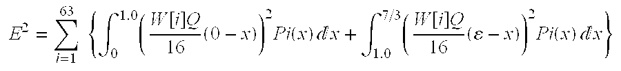
- Then, “ε” capable of minimizing this squared mean error E 2 is calculated by the following formula:

- The
quantizing circuit 11 modifies the integration of the above-described formula into a summation, and calculates an average value “ε” thereof in accordance with the following formula in the case that the quantized data whose value is negative is involved:
- In this formula, symbol “x ji” indicates a value of i-th quantized data of a j-th (j−1, - - - , N) block, and further symbol “N” denotes a total number (NY+NC) of blocks for constituting a macro block.
- It should also be noted a set of {k|1.0≦|x ki|≦7/3, 1≦k<N} indicates such a set of numbers of blocks which contain such an i-th quantized data whose absolute value is located in a range from 1.0 to 7/3 among the i-th quantized data of the respective blocks in the macro block.
- At the next step S 14, the quantizing
circuit 11 recalculates the quantized data by utilizing the quantizing scale New Q. - At a step S 15, the
representative value circuit 12 of thequantizing unit 2 converts the quantized data into representative value data by using a constant “π” calculated by the below-mentioned formula based upon the quantizing scale New Q supplied from the quantizingcircuit 11 and the quantizing scale Q supplied from the control circuit 5: - π={7/3×W[i]×Q/16−2.0×W[i]×New Q/16}/2.
- In the case of the non-intra-micro block, within such a range that the value of the quantized data calculated in correspondence with the quantizing scale Q is larger than, or equal to −2.0 as well as is smaller than, or equal to 2.0, occurrence probability of the value of this quantized data is greatly varied in response to the value of the quantized data. As a consequence, as described above, the quantizing
circuit 11 sets a new quantizing scale New Q (quantizing scale used on side of decoder) in such a manner that the average value of the quantized data within this range is made in correspondence with the value of the dequantized data on the side of the decoder. - On the other hand, in such a case that the absolute value of the quantized data is sufficiently large, occurrence probability of the value of the quantized data is substantially constant. As a consequence, with respect to each of the ranges defined by the new quantizing scales New Q, the quantized data contained in this range is converted into such representative value data having a center value of this range, so that a squared mean error between the DCT coefficient on the encoder side and the data dequantized by using the quantizing scale New Q on the decoder side must be reduced.
- In other words, in the case of the non-intra-macro block, when the value “g” of the quantized data calculated in correspondence with the quantizing scale New Q is present in a range from y to (y+1) corresponding to such an integer “y” whose absolute value is sufficiently large, the value “g” of this quantized data is converted into representative value data whose value is equal to “y+0.5”.
- Accordingly, the
representative value circuit 12 sets the range of the quantized data corresponding to the representative value data in such a manner that this range is gradually transferred to the range defined by the new quantizing scale New Q within such a range that the value of the quantized data calculated in correspondence with the quantizing scale Q is larger than, or equal to −2.0 and is smaller than, or equal to 2.0, and within such a region that the absolute value of the quantizing data is sufficiently large. - That is to say, as indicated in FIG. 14, in the case of the non-intra-macro block, when the value of the quantized data is present in a range defined from −1.0×Q/New Q to 1.0×Q×New Q (namely, range corresponding to range from −1.0 to 1.0 when quantizing scale is equal to Q), the
representative value circuit 12 sets the value of the representative value data to 0. In the case that the value of the quantized data is located in a range defined from 1.0×Q/New Q to 2.0+π/(W[i]×New Q/16), therepresentative value circuit 12 sets the value of the representative value data to 1.5. Also, in such a case that the value of the quantized data is present in a range (j≧2) defined from j +π/(W[i]×New Q/16)×2−(j−2) to (j+1)+π/(W[i]×New Q/16)×2−(j−1) (namely, value of DCT coefficient is located in range from j×W[i]×New Q/16+π×2−(j−2) to (j+1)×W[i]×New Q/16+π×2−(j−1), the value of the representative value data is set to (j+0.5). - Similarly, in the case of the non-intra-macro block, when the value of the quantized data is located in a range defined from −1.0×Q/New Q to −2.0−n/(W[i]×New Q/16), the
representative value circuit 12 sets the value of the representative value data to −1.5. Also, when the value of the quantized data is located in a range (j≧2) defined from −j−π/(W[i]×New Q/16)×2−(j−2) to −(j+1)−π/(W[i]×New Q/16)×2−(j−1), the value of the representative value data is set to −(j+0.5). - Therefore, the squared mean error between the quantized data and the representative value data can be reduced in the entire range by performing the above-explained manner.
- After the representative value data has been calculated from the quantized data in the above-described manner, the process operation is advanced to a step S 16.
- At the step S 16, the variable
length decoding device 3 variable-length-decodes Signed Level, the quantizing scale New Q, and the like, which correspond to the representative value data supplied from thequantizing unit 2, and then outputs the produced code to thetransmission buffer 4. Then, thetransmission buffer 4 temporarily stores therein the supplied code, and outputs this stored code in a predetermined transfer rate. At this time, thecontrol circuit 5 monitors the amount of the codes stored in thetransmission buffer 4, and calculates a quantizing scale Q corresponding to this monitored amount to thereby output the calculated quantizing scale to thequantizing unit 2. - Since the quantizing scale New Q is supplied as the code to the decoder, for instance, when the intra-macro block is entered, if Signed Level is equal to 1, then the dequantized data becomes 1×W[i]×New Q/16 (=α×W[i]×Q/16), and also the DCT coefficient is decoded as the average value of the above-explained range. Accordingly, the squared mean error between the DCT coefficient and the dequantized data can be reduced.
- As previously described, in the coding apparatus shown in FIG. 6, after Signed Level corresponding to the selected representative value data by considering the occurrence probability distribution of the quantized data is coded, the coded Signed Level is outputted together with the new quantizing scale New Q by the
quantizing unit 2. It should be noted that the codes produced by the above-described manner can be decoded to become the original data by the decoder suitably designed in accordance with the standardization ofMPEG 1, orMPEG 2. - Similar to such a case that the quantizing operation is carried out in correspondence with the quantizing scale Q, as described above, even when the quantizing operation is performed in correspondence with the quantizing scale New Q, in the case of the intra-macro block, the DCT coefficient whose value is located in the range defined from −0.5×W[i]×Q/16 to +0.5×W[i]×Q/16 is converted into the representative value data whose value is equal to 0. In a plurality of macro blocks, if the numbers of DCT coefficients to be converted into the representative value data whose value is equal to 0 are identical to each other, total output bit numbers of the variable length codes corresponding to the data of these macro blocks are not substantially changed. Therefore, this gives no adverse influence to the rate control of the variable length code by the
control circuit 5. - FIG. 15 schematically indicates an arrangement of a coding apparatus according to another embodiment mode of the present invention. This coding apparatus is operated in accordance with a program stored in a
memory 22, and is designed to execute the process operation of the coding apparatus in a software manner. - A
calculator 21 is controlled by acontrol circuit 25 so as to execute various sorts of calculations. - The
memory 22 stores therein the program used to execute process operations similar to the process operations by the above-described coding apparatus, and also stores calculation results of thecalculator 21 and further data of the calculations under execution. - Also, the
memory 22 may also be used as a transmission buffer similar to thetransmission buffer 4 of the coding apparatus shown in FIG. 6. - When image data is entered to an
interface 23, thisinterface 23 outputs this image data via a bus to either thecalculator 21 or thememory 22. - Another
interface 24 is designed to output a produced code to a predetermined circuit (not shown). - Next, operations of this coding apparatus will now be described.
- First, the
interface 23 receives predetermined image data, and stores this image data into thememory 22. - Next, the
calculator 21 discrete-cosine-converts this image data to thereby calculate a DCT coefficient, and processes this DCT coefficient by utilizing a quantizing scale Q supplied from thecontrol circuit 25 to thereby calculate the above-described quantized data. - Then, the
calculator 21 calculates the above-described average value “α”, or the above-explained average value “ε” from 1 micro block of quantized data, depending upon the sort of this macro block. Thiscalculator 21 calculates a quantizing scale New Q used in the decoder side from the quantizing scale Q and either the average value “α” or the average value “ε”. - Furthermore, the
calculator 21 recalculates quantized data from the DCT coefficient by utilizing this quantizing scale New Q. - Thus, the quantized data calculated by using the quantizing scale New Q in this manner is converted into the above-described representative value data. Then, Signed Level corresponding to this representative value data is variable-length-coded in combination with the quantizing scale New Q by the
calculator 21. - Thus, the produced variable length code is once stored into the
memory 22 functioning as the transmission buffer, and then is outputted via theinterface 24 in a preselected transfer rate. - It should be noted that the
control circuit 25 monitors the amount of the variable length code stored in thememory 22, and outputs a quantizing scale Q corresponding to this monitored amount to thecalculator 21. - As previously described, the coding apparatus of FIG. 15 is operated in the software manner to thereby execute a process operation similar to that of the coding apparatus of FIG. 6.
- As previously explained in detail, in accordance with the quantizing method and also the quantizing apparatus of the present invention, the reference value corresponding to a predetermined range is calculated from the occurrence probability distribution of the intermediate data within a preselected range, which is obtained by converting the input data by using the first quantizing scale. Also, while using the second quantizing scale calculated from the reference value and the first quantizing scale, the input data is converted into the intermediate data. Furthermore, the intermediate data in a predetermined range is converted into such a value that this value dequantized by the second quantizing scale becomes the reference value. Since such a value that this value dequantized by the second quantizing scale becomes the reference value and also the second quantizing scale are outputted, the squared mean error between the data dequantized in the decoder and the DCT coefficient of the encoder can be reduced.
- Also, in accordance with the coding method and the coding apparatus of the present invention, the reference value corresponding to a predetermined range is calculated from the occurrence probability distribution of the intermediate data within a preselected range, which is obtained by converting the input data produced by the data compressing unit by using the first quantizing scale. Also, while using the second quantizing scale calculated from the reference value and the first quantizing scale, the input data is converted into the intermediate data. Furthermore, the intermediate data in a predetermined range is converted into such a value that this value dequantized by the second quantizing scale becomes the reference value. Since such a value that this value dequantized by the second quantizing scale becomes the reference value and also the second quantizing scale are decoded to be outputted, the squared mean error between the data dequantized in the decoder and the DCT coefficient of the encoder can be reduced. Also, the produced code may be decoded by the decoder suitably designed to the standardization of the MPEG system.
- It should be understood that while the present invention has been described as the exemplification, as apparently from the foregoing descriptions, the present invention is not limited to those embodiments, but may be modified, changed, or substituted without departing from the technical spirit and the technical scope of the invention.
Claims (18)
1. A quantizing apparatus for quantizing input data in correspondence with a predetermined quantizing scale, comprising:
a first calculating unit for calculating a reference value from an occurrence probability distribution of intermediate data in a predetermined range, which is obtained by converting said input data by using a first quantizing scale, said reference value corresponding to said predetermined range;
a second calculating unit for calculating a second quantizing scale from said reference value and said first quantizing scale;
a first converting unit for converting said input data into said intermediate data by utilizing said second quantizing scale;
a second converting unit for converting the intermediate data in said predetermined range into such a value that a value dequantized by said second quantizing scale becomes said reference value; and
an output unit for outputting both such a value that said value dequantized by said second quantizing scale becomes said reference value, and said second quantizing scale.
2. A quantizing apparatus as claimed in claim 1 wherein:
said reference value is equal to an average value of the intermediate data having a value within said predetermined range.
3. A quantizing apparatus as claimed in claim 1 wherein:
said intermediate data is equal to data which is directly proportional to such a value obtained by dividing said input data by a product between a weighting coefficient corresponding to said input data, and one of said first quantizing scale and said second quantizing scale.
4. A quantizing method for quantizing input data in correspondence with a predetermined quantizing scale, comprising:
a step for calculating a reference value from an occurrence probability distribution of intermediate data in a predetermined range, which is obtained by converting said input data by using a first quantizing scale, said reference value corresponding to said predetermined range;
a step for calculating a second quantizing scale from said reference value and said first quantizing scale;
a step for converting said input data into said intermediate data by utilizing said second quantizing scale;
a step for converting the intermediate data in said predetermined range into such a value that a value dequantized by said second quantizing scale becomes said reference value; and
a step for outputting both such a value that said value dequantized by said second quantizing scale becomes said reference value, and said second quantizing scale.
5. A quantizing method as claimed in claim 4 wherein:
said reference value is equal to an average value of the intermediate data having a value within said predetermined range.
6. A quantizing method as claimed in claim 4 wherein:
said intermediate data is equal to data which is directly proportional to such a value obtained by dividing said input data by a product between a weighting coefficient corresponding to said input data, and one of said first quantizing scale and said second quantizing scale.
7. A coding apparatus for coding an image signal, comprising:
a data converting unit for frequency-converting the image signal and for outputting image conversion data corresponding to said image signal;
a quantizing unit for quantizing said image conversion data by a predetermined quantizing scale;
a coding unit for coding the quantized image conversion data; and
a calculating unit for calculating said quantizing scale in correspondence with an amount of a code outputted from said coding unit; wherein said quantizing unit is further comprised of:
a first calculating unit for calculating a reference value from an occurrence probability distribution of intermediate data in a predetermined range, which is obtained by converting said input data by using a first quantizing scale, said reference value corresponding to said predetermined range;
a second calculating unit for calculating a second quantizing scale from said reference value and said first quantizing scale;
a first converting unit for converting said input data into said intermediate data by utilizing said second quantizing scale;
a second converting unit for converting the intermediate data in said predetermined range into such a value that a value dequantized by said second quantizing scale becomes said reference value; and
an output unit for outputting both such a value that said value dequantized by said second quantizing scale becomes said reference value, and said second quantizing scale.
8. A coding apparatus as claimed in claim 7 wherein:
said reference value is equal to an average value of the intermediate data having a value within said predetermined range.
9. A coding apparatus as claimed in claim 7 wherein:
said intermediate data is equal to data which is directly proportional to such a value obtained by dividing said input data by a product between a weighting coefficient corresponding to said input data, and one of said first quantizing scale and said second quantizing scale.
10. A coding method for coding an image signal, comprising:
a step for frequency-converting the image signal and for outputting image conversion data corresponding to said image signal;
a step for quantizing said image conversion data by a predetermined quantizing scale;
a step for coding the quantized image conversion data; and
a step for calculating said quantizing scale in correspondence with an amount of a code outputted from said coding unit; wherein said quantizing step is further comprised of:
a step for calculating a reference value from an occurrence probability distribution of intermediate data in a predetermined range, which is obtained by converting said input data by using a first quantizing scale, said reference value corresponding to said predetermined range;
a step for calculating a second quantizing scale from said reference value and said first quantizing scale;
a step for converting said input data into said intermediate data by utilizing said second quantizing scale;
a step for converting the intermediate data in said predetermined range into such a value that a value dequantized by said second quantizing scale becomes said reference value; and
a step for outputting both such a value that said value dequantized by said second quantizing scale becomes said reference value, and said second quantizing scale.
11. A coding method as claimed in claim 10 wherein:
said reference value is equal to an average value of the intermediate data having a value within said predetermined range.
12. A coding method as claimed in claim 10 wherein:
said intermediate data is equal to data which is directly proportional to such a value obtained by dividing said input data by a product between a weighting coefficient corresponding to said input data, and one of said first quantizing scale and said second quantizing scale.
13. In a machine-readable-program storage medium for storing a program instruction executable by the machine so as to execute a process step for quantizing image data, said process step comprising:
a step for calculating a reference value from an occurrence probability distribution of intermediate data in a predetermined range, which is obtained by converting said input data by using a first quantizing scale, said reference value corresponding to said predetermined range;
a step for calculating a second quantizing scale from said reference value and said first quantizing scale;
a step for converting said input data into said intermediate data by utilizing said second quantizing scale;
a step for converting the intermediate data in said predetermined range into such a value that a value dequantized by said second quantizing scale becomes said reference value; and
a step for outputting both such a value that said value dequantized by said second quantizing scale becomes said reference value, and said second quantizing scale.
14. A machine-readable-program storage medium as claimed in claim 13 wherein:
said reference value is equal to an average value of the intermediate data having a value within said predetermined range.
15. A machine-readable-program storage medium as claimed in claim 13 wherein:
said intermediate data is equal to data which is directly proportional to such a value obtained by dividing said input data by a product between a weighting coefficient corresponding to said input data, and one of said first quantizing scale and said second quantizing scale.
16. In a machine-readable-program storage medium for storing a program instruction executable by the machine so as to execute a process step for quantizing image data, said process step comprising:
a step for frequency-converting the image signal and for outputting image conversion data corresponding to said image signal;
a step for quantizing said image conversion data by a predetermined quantizing scale;
a step for coding the quantized image conversion data; and
a step for calculating said quantizing scale in correspondence with an amount of a code outputted from said coding unit; wherein said quantizing step is further comprised of:
a step for calculating a reference value from an occurrence probability distribution of intermediate data in a predetermined range, which is obtained by converting said input data by using a first quantizing scale, said reference value corresponding to said predetermined range;
a step for calculating a second quantizing scale from said reference value and said first quantizing scale;
a step for converting said input data into said intermediate data by utilizing said second quantizing scale;
a step for converting the intermediate data in said predetermined range into such a value that a value dequantized by said second quantizing scale becomes said reference value; and
a step for outputting both such a value that said value dequantized by said second quantizing scale becomes said reference value, and said second quantizing scale.
17. A machine-readable-program storage medium as claimed in claim 16 wherein:
said reference value is equal to an average value of the intermediate data having a value within said predetermined range.
18. A machine-readable-program storage medium as claimed in claim 16 wherein:
said intermediate data is equal to data which is directly proportional to such a value obtained by dividing said input data by a product between a weighting coefficient corresponding to said input data, and one of said first quantizing scale and said second quantizing scale.
Applications Claiming Priority (2)
| Application Number | Priority Date | Filing Date | Title |
|---|---|---|---|
| JP25427396A JPH10107644A (en) | 1996-09-26 | 1996-09-26 | Quantization device and method, and coder and method |
| JP8-254273 | 1996-09-26 |
Publications (1)
| Publication Number | Publication Date |
|---|---|
| US20020044602A1 true US20020044602A1 (en) | 2002-04-18 |
Family
ID=17262688
Family Applications (1)
| Application Number | Title | Priority Date | Filing Date |
|---|---|---|---|
| US08/935,927 Abandoned US20020044602A1 (en) | 1996-09-26 | 1997-09-23 | Dual quantization method and apparatus for minimum error |
Country Status (2)
| Country | Link |
|---|---|
| US (1) | US20020044602A1 (en) |
| JP (1) | JPH10107644A (en) |
Cited By (27)
| Publication number | Priority date | Publication date | Assignee | Title |
|---|---|---|---|---|
| US20030081683A1 (en) * | 2001-10-29 | 2003-05-01 | Samsung Electronics Co., Ltd. | Motion vector estimation method and apparatus thereof |
| WO2004047425A2 (en) * | 2002-11-15 | 2004-06-03 | Qualcomm Incorporated | Apparatus and method for multiple description encoding |
| US20040208392A1 (en) * | 2003-03-17 | 2004-10-21 | Raveendran Vijayalakshmi R. | Method and apparatus for improving video quality of low bit-rate video |
| US20050013500A1 (en) * | 2003-07-18 | 2005-01-20 | Microsoft Corporation | Intelligent differential quantization of video coding |
| US20050036699A1 (en) * | 2003-07-18 | 2005-02-17 | Microsoft Corporation | Adaptive multiple quantization |
| US20050041738A1 (en) * | 2003-07-18 | 2005-02-24 | Microsoft Corporation | DC coefficient signaling at small quantization step sizes |
| US20050238096A1 (en) * | 2003-07-18 | 2005-10-27 | Microsoft Corporation | Fractional quantization step sizes for high bit rates |
| US20070237222A1 (en) * | 2006-04-07 | 2007-10-11 | Microsoft Corporation | Adaptive B-picture quantization control |
| US20070248163A1 (en) * | 2006-04-07 | 2007-10-25 | Microsoft Corporation | Quantization adjustments for DC shift artifacts |
| US20070258518A1 (en) * | 2006-05-05 | 2007-11-08 | Microsoft Corporation | Flexible quantization |
| EP1942462A1 (en) * | 2002-11-15 | 2008-07-09 | Qualcomm Incorporated | Apparatus and method for multiple description encoding |
| US20080198935A1 (en) * | 2007-02-21 | 2008-08-21 | Microsoft Corporation | Computational complexity and precision control in transform-based digital media codec |
| US20080240250A1 (en) * | 2007-03-30 | 2008-10-02 | Microsoft Corporation | Regions of interest for quality adjustments |
| US20080240235A1 (en) * | 2007-03-26 | 2008-10-02 | Microsoft Corporation | Adaptive deadzone size adjustment in quantization |
| US20080260278A1 (en) * | 2007-04-18 | 2008-10-23 | Microsoft Corporation | Encoding adjustments for animation content |
| US20090245587A1 (en) * | 2008-03-31 | 2009-10-01 | Microsoft Corporation | Classifying and controlling encoding quality for textured, dark smooth and smooth video content |
| US20090296808A1 (en) * | 2008-06-03 | 2009-12-03 | Microsoft Corporation | Adaptive quantization for enhancement layer video coding |
| US7801383B2 (en) | 2004-05-15 | 2010-09-21 | Microsoft Corporation | Embedded scalar quantizers with arbitrary dead-zone ratios |
| US20110116543A1 (en) * | 2001-09-18 | 2011-05-19 | Microsoft Corporation | Block transform and quantization for image and video coding |
| US7995649B2 (en) | 2006-04-07 | 2011-08-09 | Microsoft Corporation | Quantization adjustment based on texture level |
| US8059721B2 (en) | 2006-04-07 | 2011-11-15 | Microsoft Corporation | Estimating sample-domain distortion in the transform domain with rounding compensation |
| US8130828B2 (en) | 2006-04-07 | 2012-03-06 | Microsoft Corporation | Adjusting quantization to preserve non-zero AC coefficients |
| US8238424B2 (en) | 2007-02-09 | 2012-08-07 | Microsoft Corporation | Complexity-based adaptive preprocessing for multiple-pass video compression |
| US20120230395A1 (en) * | 2011-03-11 | 2012-09-13 | Louis Joseph Kerofsky | Video decoder with reduced dynamic range transform with quantization matricies |
| US8331438B2 (en) | 2007-06-05 | 2012-12-11 | Microsoft Corporation | Adaptive selection of picture-level quantization parameters for predicted video pictures |
| US8422546B2 (en) | 2005-05-25 | 2013-04-16 | Microsoft Corporation | Adaptive video encoding using a perceptual model |
| US10554985B2 (en) | 2003-07-18 | 2020-02-04 | Microsoft Technology Licensing, Llc | DC coefficient signaling at small quantization step sizes |
-
1996
- 1996-09-26 JP JP25427396A patent/JPH10107644A/en not_active Withdrawn
-
1997
- 1997-09-23 US US08/935,927 patent/US20020044602A1/en not_active Abandoned
Cited By (67)
| Publication number | Priority date | Publication date | Assignee | Title |
|---|---|---|---|---|
| US20110116543A1 (en) * | 2001-09-18 | 2011-05-19 | Microsoft Corporation | Block transform and quantization for image and video coding |
| US8971405B2 (en) | 2001-09-18 | 2015-03-03 | Microsoft Technology Licensing, Llc | Block transform and quantization for image and video coding |
| US7333543B2 (en) * | 2001-10-29 | 2008-02-19 | Samsung Electronics Co., Ltd. | Motion vector estimation method and apparatus thereof |
| US20030081683A1 (en) * | 2001-10-29 | 2003-05-01 | Samsung Electronics Co., Ltd. | Motion vector estimation method and apparatus thereof |
| US7564382B2 (en) | 2002-11-15 | 2009-07-21 | Qualcomm Incorporated | Apparatus and method for multiple description encoding |
| EP1942462A1 (en) * | 2002-11-15 | 2008-07-09 | Qualcomm Incorporated | Apparatus and method for multiple description encoding |
| WO2004047425A2 (en) * | 2002-11-15 | 2004-06-03 | Qualcomm Incorporated | Apparatus and method for multiple description encoding |
| EP1579577A2 (en) * | 2002-11-15 | 2005-09-28 | QUALCOMM Incorporated | Apparatus and method for multiple description encoding |
| EP1579577A4 (en) * | 2002-11-15 | 2006-01-18 | Qualcomm Inc | Apparatus and method for multiple description encoding |
| US7061404B2 (en) | 2002-11-15 | 2006-06-13 | Qualcomm Incorporated | Apparatus and method for multiple description encoding |
| US20060197691A1 (en) * | 2002-11-15 | 2006-09-07 | Irvine Ann C | Apparatus and method for multiple description encoding |
| CN1726644B (en) * | 2002-11-15 | 2010-04-28 | 高通股份有限公司 | Apparatus and method for multiple description encoding |
| WO2004047425A3 (en) * | 2002-11-15 | 2004-11-18 | Qualcomm Inc | Apparatus and method for multiple description encoding |
| US7561073B2 (en) | 2002-11-15 | 2009-07-14 | Qualcomm Incorporated | Apparatus and method for multiple description encoding |
| AU2003291057B2 (en) * | 2002-11-15 | 2009-04-23 | Qualcomm Incorporated | Apparatus and method for multiple description encoding |
| US20040208392A1 (en) * | 2003-03-17 | 2004-10-21 | Raveendran Vijayalakshmi R. | Method and apparatus for improving video quality of low bit-rate video |
| US7995849B2 (en) | 2003-03-17 | 2011-08-09 | Qualcomm, Incorporated | Method and apparatus for improving video quality of low bit-rate video |
| US10554985B2 (en) | 2003-07-18 | 2020-02-04 | Microsoft Technology Licensing, Llc | DC coefficient signaling at small quantization step sizes |
| US11272194B2 (en) * | 2003-07-18 | 2022-03-08 | Microsoft Technology Licensing, Llc | Fractional quantization step sizes for high bit rates |
| US20050036699A1 (en) * | 2003-07-18 | 2005-02-17 | Microsoft Corporation | Adaptive multiple quantization |
| US10063863B2 (en) | 2003-07-18 | 2018-08-28 | Microsoft Technology Licensing, Llc | DC coefficient signaling at small quantization step sizes |
| US9313509B2 (en) | 2003-07-18 | 2016-04-12 | Microsoft Technology Licensing, Llc | DC coefficient signaling at small quantization step sizes |
| US20050013500A1 (en) * | 2003-07-18 | 2005-01-20 | Microsoft Corporation | Intelligent differential quantization of video coding |
| US10958916B2 (en) * | 2003-07-18 | 2021-03-23 | Microsoft Technology Licensing, Llc | Fractional quantization step sizes for high bit rates |
| US10659793B2 (en) | 2003-07-18 | 2020-05-19 | Microsoft Technology Licensing, Llc | DC coefficient signaling at small quantization step sizes |
| US20220191518A1 (en) * | 2003-07-18 | 2022-06-16 | Microsoft Technology Licensing, Llc | Fractional quantization step sizes for high bit rates |
| US8218624B2 (en) * | 2003-07-18 | 2012-07-10 | Microsoft Corporation | Fractional quantization step sizes for high bit rates |
| US11638017B2 (en) * | 2003-07-18 | 2023-04-25 | Microsoft Technology Licensing, Llc | Fractional quantization step sizes for high bit rates |
| US7738554B2 (en) | 2003-07-18 | 2010-06-15 | Microsoft Corporation | DC coefficient signaling at small quantization step sizes |
| US20050041738A1 (en) * | 2003-07-18 | 2005-02-24 | Microsoft Corporation | DC coefficient signaling at small quantization step sizes |
| US20050238096A1 (en) * | 2003-07-18 | 2005-10-27 | Microsoft Corporation | Fractional quantization step sizes for high bit rates |
| US7801383B2 (en) | 2004-05-15 | 2010-09-21 | Microsoft Corporation | Embedded scalar quantizers with arbitrary dead-zone ratios |
| US8422546B2 (en) | 2005-05-25 | 2013-04-16 | Microsoft Corporation | Adaptive video encoding using a perceptual model |
| US7974340B2 (en) | 2006-04-07 | 2011-07-05 | Microsoft Corporation | Adaptive B-picture quantization control |
| US8503536B2 (en) | 2006-04-07 | 2013-08-06 | Microsoft Corporation | Quantization adjustments for DC shift artifacts |
| US8130828B2 (en) | 2006-04-07 | 2012-03-06 | Microsoft Corporation | Adjusting quantization to preserve non-zero AC coefficients |
| US20070237222A1 (en) * | 2006-04-07 | 2007-10-11 | Microsoft Corporation | Adaptive B-picture quantization control |
| US20070248163A1 (en) * | 2006-04-07 | 2007-10-25 | Microsoft Corporation | Quantization adjustments for DC shift artifacts |
| US7995649B2 (en) | 2006-04-07 | 2011-08-09 | Microsoft Corporation | Quantization adjustment based on texture level |
| US8059721B2 (en) | 2006-04-07 | 2011-11-15 | Microsoft Corporation | Estimating sample-domain distortion in the transform domain with rounding compensation |
| US8767822B2 (en) | 2006-04-07 | 2014-07-01 | Microsoft Corporation | Quantization adjustment based on texture level |
| US8249145B2 (en) | 2006-04-07 | 2012-08-21 | Microsoft Corporation | Estimating sample-domain distortion in the transform domain with rounding compensation |
| US9967561B2 (en) | 2006-05-05 | 2018-05-08 | Microsoft Technology Licensing, Llc | Flexible quantization |
| US8184694B2 (en) | 2006-05-05 | 2012-05-22 | Microsoft Corporation | Harmonic quantizer scale |
| US20070258518A1 (en) * | 2006-05-05 | 2007-11-08 | Microsoft Corporation | Flexible quantization |
| US20070258519A1 (en) * | 2006-05-05 | 2007-11-08 | Microsoft Corporation | Harmonic quantizer scale |
| US8588298B2 (en) | 2006-05-05 | 2013-11-19 | Microsoft Corporation | Harmonic quantizer scale |
| US8711925B2 (en) | 2006-05-05 | 2014-04-29 | Microsoft Corporation | Flexible quantization |
| US8238424B2 (en) | 2007-02-09 | 2012-08-07 | Microsoft Corporation | Complexity-based adaptive preprocessing for multiple-pass video compression |
| US8942289B2 (en) * | 2007-02-21 | 2015-01-27 | Microsoft Corporation | Computational complexity and precision control in transform-based digital media codec |
| US20080198935A1 (en) * | 2007-02-21 | 2008-08-21 | Microsoft Corporation | Computational complexity and precision control in transform-based digital media codec |
| US8498335B2 (en) | 2007-03-26 | 2013-07-30 | Microsoft Corporation | Adaptive deadzone size adjustment in quantization |
| US20080240235A1 (en) * | 2007-03-26 | 2008-10-02 | Microsoft Corporation | Adaptive deadzone size adjustment in quantization |
| US20080240250A1 (en) * | 2007-03-30 | 2008-10-02 | Microsoft Corporation | Regions of interest for quality adjustments |
| US8576908B2 (en) | 2007-03-30 | 2013-11-05 | Microsoft Corporation | Regions of interest for quality adjustments |
| US8243797B2 (en) | 2007-03-30 | 2012-08-14 | Microsoft Corporation | Regions of interest for quality adjustments |
| US20080260278A1 (en) * | 2007-04-18 | 2008-10-23 | Microsoft Corporation | Encoding adjustments for animation content |
| US8442337B2 (en) | 2007-04-18 | 2013-05-14 | Microsoft Corporation | Encoding adjustments for animation content |
| US8331438B2 (en) | 2007-06-05 | 2012-12-11 | Microsoft Corporation | Adaptive selection of picture-level quantization parameters for predicted video pictures |
| US8189933B2 (en) | 2008-03-31 | 2012-05-29 | Microsoft Corporation | Classifying and controlling encoding quality for textured, dark smooth and smooth video content |
| US20090245587A1 (en) * | 2008-03-31 | 2009-10-01 | Microsoft Corporation | Classifying and controlling encoding quality for textured, dark smooth and smooth video content |
| US10306227B2 (en) | 2008-06-03 | 2019-05-28 | Microsoft Technology Licensing, Llc | Adaptive quantization for enhancement layer video coding |
| US8897359B2 (en) | 2008-06-03 | 2014-11-25 | Microsoft Corporation | Adaptive quantization for enhancement layer video coding |
| US9571840B2 (en) | 2008-06-03 | 2017-02-14 | Microsoft Technology Licensing, Llc | Adaptive quantization for enhancement layer video coding |
| US9185418B2 (en) | 2008-06-03 | 2015-11-10 | Microsoft Technology Licensing, Llc | Adaptive quantization for enhancement layer video coding |
| US20090296808A1 (en) * | 2008-06-03 | 2009-12-03 | Microsoft Corporation | Adaptive quantization for enhancement layer video coding |
| US20120230395A1 (en) * | 2011-03-11 | 2012-09-13 | Louis Joseph Kerofsky | Video decoder with reduced dynamic range transform with quantization matricies |
Also Published As
| Publication number | Publication date |
|---|---|
| JPH10107644A (en) | 1998-04-24 |
Similar Documents
| Publication | Publication Date | Title |
|---|---|---|
| US20020044602A1 (en) | Dual quantization method and apparatus for minimum error | |
| US5903676A (en) | Context-based, adaptive, lossless image codec | |
| US7130348B2 (en) | Systems and methods for reduced bit-depth processing in video-related data | |
| JP2633793B2 (en) | Method and apparatus for variable length encoding / decoding of video data | |
| US5822003A (en) | Method and apparatus for performing fast reduced coefficient discrete cosine transforms | |
| CN100459706C (en) | Controlling apparatus and method for bit rate | |
| CN1428051A (en) | Approximate IDCT for scalable video and image decoding of computational complexity | |
| EP0843481A1 (en) | Image encoder, image decoder, image decoding method, and image transmitting system | |
| US6850566B2 (en) | Implementation of quantization for SIMD architecture | |
| US20030128887A1 (en) | Two-dimensional orthogonal transformation and quantization method and its device and program | |
| JP2002369198A (en) | Encoding selection equipment, encoding equipment and its method | |
| US20020173952A1 (en) | Coding | |
| US7649940B2 (en) | Image encoding apparatus and method | |
| US5825422A (en) | Method and apparatus for encoding a video signal based on inter-block redundancies | |
| US6347115B1 (en) | Method and system for predictive coding of images treated with the Roberts Method | |
| US20050084157A1 (en) | Method for deblocking and transcoding a media stream | |
| KR100502403B1 (en) | Decoder of mpeg-2 | |
| JPH0795415A (en) | Method and device for picture communication | |
| JPH0946709A (en) | Picture encoding device | |
| US20050276332A1 (en) | Method of communicating data within a coder | |
| KR100201411B1 (en) | Reverse quantization | |
| JP3125615B2 (en) | Image encoding device and image encoding / decoding device | |
| KR0141193B1 (en) | Compressed encoded method and apparatus | |
| JP3387516B2 (en) | Image encoding apparatus and method | |
| JPH06326614A (en) | Encoder |
Legal Events
| Date | Code | Title | Description |
|---|---|---|---|
| AS | Assignment |
Owner name: SONY CORPORATION, JAPAN Free format text: ASSIGNMENT OF ASSIGNORS INTEREST;ASSIGNOR:OHKI, MITSUHARU;REEL/FRAME:009616/0392 Effective date: 19980728 |
|
| STCB | Information on status: application discontinuation |
Free format text: ABANDONED -- FAILURE TO RESPOND TO AN OFFICE ACTION |