US1979296A - Television apparatus - Google Patents
Television apparatus Download PDFInfo
- Publication number
- US1979296A US1979296A US569763A US56976331A US1979296A US 1979296 A US1979296 A US 1979296A US 569763 A US569763 A US 569763A US 56976331 A US56976331 A US 56976331A US 1979296 A US1979296 A US 1979296A
- Authority
- US
- United States
- Prior art keywords
- fork
- magnet
- light
- circuit
- frequency
- Prior art date
- Legal status (The legal status is an assumption and is not a legal conclusion. Google has not performed a legal analysis and makes no representation as to the accuracy of the status listed.)
- Expired - Lifetime
Links
Images


Classifications
-
- H—ELECTRICITY
- H04—ELECTRIC COMMUNICATION TECHNIQUE
- H04N—PICTORIAL COMMUNICATION, e.g. TELEVISION
- H04N3/00—Scanning details of television systems; Combination thereof with generation of supply voltages
- H04N3/02—Scanning details of television systems; Combination thereof with generation of supply voltages by optical-mechanical means only
- H04N3/08—Scanning details of television systems; Combination thereof with generation of supply voltages by optical-mechanical means only having a moving reflector
-
- Y—GENERAL TAGGING OF NEW TECHNOLOGICAL DEVELOPMENTS; GENERAL TAGGING OF CROSS-SECTIONAL TECHNOLOGIES SPANNING OVER SEVERAL SECTIONS OF THE IPC; TECHNICAL SUBJECTS COVERED BY FORMER USPC CROSS-REFERENCE ART COLLECTIONS [XRACs] AND DIGESTS
- Y10—TECHNICAL SUBJECTS COVERED BY FORMER USPC
- Y10T—TECHNICAL SUBJECTS COVERED BY FORMER US CLASSIFICATION
- Y10T74/00—Machine element or mechanism
- Y10T74/18—Mechanical movements
- Y10T74/18056—Rotary to or from reciprocating or oscillating
- Y10T74/18144—Overcoming dead center
Definitions
- My invention relates to an apparatus for transmitting visible representations of objects by means of the electric current, commonly called television.
- a further object of this invention is to prol5 vide a means for transmitting and receiving secret messages, including charts, maps, plans, visual images and the like.
- the invention consists in the construction, combination and arrangement of parts as will be herein-.
- Fig. 1 is a diagrammatic view of the tuning fork driving circuits
- Fig. 2 shows the projector mechanism at the receiving station
- Figs. 3 and 4 show modified forms in which the mirrows are mounted on a string galvanometer or an oscillograph
- Fig. 5 represents a circuit in which a piezoelectric crystal vibratoris used to control the oscillator tube that governs the frequency of the tuning fork;
- Fig. 6 shows schematically the arrangement of the analyzer at the transmitting station
- Fig. '7 is a diagram of the synchronizing circuits at the transmitting station
- Fig. 8 is a diagram of the synchronizing circuits at the receiving station
- Fig. 9 shows in a diagrammatic side view an arrangement adapted to secret television transmission
- Fig. 10 is a diagrammatic plan view of. the
- the analyzing unit at the transmitting station is essentially of the same general design as the projecting unit of the receiving station, as each includes two tuning forks driven at definite frequencies in planes at right angles'to each other, and with a mirror or other reflecting element on a prong of each so that light from one is reflected to and by the other.
- Tuning fork 38 which is part of the receiving apparatus, has a right angled prism 37 secured to one prong, though this prism may be replaced by a mirror or other equivalent device.
- Adjustable loading screws 12 held fixed in place by lock nuts 13 are provided on the ends of the prongs to make it possible to vary the natural period of vibration of the fork.
- Tuning fork 38 is caused to vibrate by an electrc-magnet 14 disposed to act on one prong of the fork.
- the power for energizing the magnet is derived from the plate circuitof vacuum tube" 15, in which circuit the magnet is connected.
- Switch 16 is provided to cut off the current when desired.
- a second electro-magn et 17, connected in the grid circuit of tube 15, is placed adjacent to the other prong of the fork.
- magnet 14 When switch 16 is closed magnet 14 is energized and attracts the adjacent prong of fork 38, which causes the other prong to swing toward magnet 1'7, whichreduces the air gap of the latter magnet and increases the magnetic flux through it, thus inducing in the coils of magnet 17 a voltage that is impressed upon the grid of tube 15 and cuts down the current in the plate circuit. Diminution of the current through magnet 14 decreases its strength and the prong of the fork is released to move back, "as does the other prong also.
- magnet 1'7 augments the reluctance of the magnetic circuit and reduces the flux, so that a voltage is set up in the coils of magnet 1'7, which, being impressedon the grid, reduces the negative potential thereof and permits an increased flow of current in the plate circuit that passes through magnet 14 and again attracts the prong adjacent thereto;
- Magnet '14 may conveniently be called the driver magnet and magnet 1'7 may be called the grid control magnet.
- the vibration of fork 38 may be varied to get it into step with the fork of like frequency in the transmitter by means of a magnet 18 placed between the prongs of the fork, and energized from plate battery 19.
- a vibratile reed 20 In the circuit of this magnet is a vibratile reed 20 that may be periodically moved against contact 21 by the teeth on a starwheel 22 operable manually by a crank 23.
- the current strength in this circuit may be regulated by variable resistance 24 or by changing the connection of this circuit to battery 19.
- Periodic energize.- tion of magnet 18 by the alternate opening and closing of the circuit by means of reed 20 will affect the vibration'o'f fork 38, and it may thus be caused to vibrate in exact harmony with the other forks of its frequency in the system.
- This device 18202l-22-2324, etc., is further used .to start the fork vibrating in case the type of driving circuit used is such that self-starting (or fork vibrations) feature is not incorporated.
- the analyzer at the transmitting station is shown in Fig. 6.
- Light from::source:25. is concentrated on an aperture in screen 26 by lens 27, from whence it is directed upon prism 11 on fork 10, hereinafter called the high speed. fork,.by lens 32.
- Fork 10 is driven by a magnetlike Iiand actuates a grid control magnet like 17, above explained.
- the light .from prism 28 falls upon the object whereof. the representation. is to bev transmitted, in tthe-present instance shown as a photo film. 32, by way of example.
- the light from film .32- is focussed onaphoto-electric cell 33 by lens 34, the .currents from which are amplified for transmission byamplifier 35.
- the object to be televised is illuminated by a source of light external to the analyzer :and -the.light reflected by the object is Jeflected to'the prism' 28,:refracted to the prism 11 andiromprismll throughthelens 32 to a photo- ;electric-.ce1l;33 which will now-be .locatedin the position of the aperture in screen 26.
- .Tuning;fork 10 is designed to have a natural frequency-of. 500, .750, 1.000, or 1500 vibrations per second, .as is foundmost suited .to the 'class of ,transmission-involved i. e., whether still pictures, moving pictures, or :moving rscene.
- Fork 29 may have a frequency of 8, 15,120.25, or30 vibrations per second.
- the variation .in .frequency allowableito both forks'willbe limitedtoa considerable .extentby the intensity ofthe-source of'light avail- - able.
- the light which reaches cell;33.- after:having-passed through the film 32 or -having :been reflected to Fit from the subject will be of .varying intensity, idepending'upon thedenjsity o'f'shadinglin t-he different parts-of the'film :or upon-theamount'ofilightreflected from differ- --ent parts of thersubject andwill result in the prolduction ofian.
- the apparatus --at -the receiving station comiprisescan amplifier 34'through whichthe incoming ;current :from the transmitter is passed and :whichu's :connectedxto .a source-of light, shown for illustration in Fig. 2 as a neon tube 35, whereof the intensity is controlled by the current received from amplifier 34.
- the light from source 35 is focussed by lens 36 on prism 37 carried by a prong of high speed tuning fork 38, by which it is reflected to prism 39 on a prong of low speed fork 40, the beam from the latter prism passing through dispersing lens 41 and thence upon screen 42.
- Fork is driven by electro-magnet .42 and actuates a grid control magnet 43, as in the transmitting apparatus.
- .fork 38 has a driving magnet and a grid control magnet associated therewith as be fore described. Forks 38 and 40 of the receiving chronism is obtained and the picture is sharp and distinct.
- the circuits of the transmitting apparatus are shown in Fig. 7, with the forks omitted for sim-' plicity.
- the plate of vacuum tube 43 is connected todriver magnet 44 and the grid thereof is connected to grid control magnet 45 constituting the circuit for the-high speed fork.
- inductances 49 and 50 is inductively coupled to the grid circuit of tube 43 at 51.
- the filter circuit is also inductively coupled to theiplate circuit of tube 52 of the low speed fork at 53, the
- said circuit also including driving magnet 54.
- the grid circuit of tube 52 includes the grid control magnet 55.
- the circuit of the low speed fork . is inductively coupled to the grid of the tube 56 at5'7,.the amplifier circuit having any desirable number of stages of. amplification, here represented'by the tube mentioned and tube 58 with the resistances 59 and 60 and condenser 61, the output from the amplifier being indicated'at 62.
- values of the inductances and capacities of the filter circuit are such that thecircuit of the low speed fork can influence the circuit ofthe high speed fork, but prevent the reverse operation.
- the purpose of this arrangement is to insure that atperiodic intervals, that is, each time the vibrations of the two forks are in phase, the vibrations of thelow speedfork can act upon the high speed fork to keepthe two forks relatively in step, as the vibration rate of the high speed fork is some definite number of times as great as that of the low speed fork.
- the circuits at the receiving station are shown in Fig. 8.
- the impulses are received either by means of antenna 63 and the devices associated therewith, or from wire lines 64, depending upon the means selected for transmission.
- the signals are impressed through coupling 65 upon the amplifying circuits comprising tubes 66 and 67, resistances68 and 63, and condenser '70.
- the output of tube 67 is coupled at '71 to a filter comprising inductances '72 and 73, and condensers '74, '75, and 76. (This filter will'be omitted unless a synchronizing impulse is impressed on the transmitted wave by means of a transformer 77, as shown in Fig. 3. When the filter is omitted the low speed fork circuit is coupled to theamplifier at 71.)
- the low'speed fork circuit is coupled to the filter circuit at 78.
- This circuit comprises vacuum tube .79, driving magnet 89 and-grid control .magnet 81.
- a second filter circuit is coupled to the low speed fork circuit at 82, and consists of inductances 83 and 84, and condensers 85, 86, and 87.
- the purpose of this filter is the same as that of the filter between the two fork circuits at the transmitting station; viz., to permit the impulses in the low speed fork circuit toaffect the high speed fork circuit, but to prevent reciprocal action.
- the second filter is coupled to the cir- 'cuit of. the high speed fork at 88, the circuit of this fork including tube 89, driving magnet 90, and grid control magnet 91.
- the mirrors are mounted on the wires of string galvanometers disposed toact as an oscillograph, instead of on the prongs of tuning forks.
- the circuits of one fork and galvanometer are shown in Fig. 3 and the disposition of the two galvanometers is diagrammatically indicated in Fig. 4.
- the plate circuit of tube 92 includes inductive coupling member 93, inductive coupling member 94, and
- driving magnet 95 for a low speed fork while the grid circuit thereof includes inductive coupling member 96 and grid control magnet 9'7.
- a tuning fork is driven by magnet 95 and varies the flux through magnet 9'7 as before explained, so that there is set up a periodic variation of the current in the plate circuit, which variation is impressed upon the suspension wires of mirror 98 between the poles of magnet 99 in a manner well known, through transformer 100 of which element 94 is a part.
- Light from source 101 is directed upon mirror 102 suspended between the poles of magnet 104 upon wires 103 by the lenses 105, 106, and 107, the vibrations of mirror 102 being controlled by a high speed fork connected thereto in the manner shown in Fig.
- Transformer 77 is employed to impress upon the tube 92 a synchronizing impulse, which will be imposed upon the plate current and, through transformer 109, will be passed to the transmitting apparatus. This impulse will be picked up and impressed upon the slow speed fork at the receiving station and so will keep the corresponding frequency forks at the two stations in step.
- the decrement of the synchronizing signals may be made suii'iciently large to avoid any noticeable interference with the television signal, thus permitting the continued transmission of a synchronizing signal on the same channel used for the television signal, if desired.
- the synchronizing signal may be used with any of the embodiments of my invention heretofore set forth.
- the device shown in Fig. 5 may be employed.
- the frequency of an oscillator tube 110 is accurately controlled by a piezo-electric crystal oscillator 111 connected tothe grid of the tube.
- Variable condenser 112 is connected across the terminals of the oscillator, and variable condenser 113 and inductance 114 connected in parallel with each other are in series with crystal oscillator 111.
- the plate of tube 110 is connected to the other common terminal of condenser 113 and inductance 114.”
- the filament of tube 110 is connected to inductance 114 through condenser 115, and the grid of the tube is connected to the filament through resistance 116.
- the natural period of crystal oscillator 111 should be the same as that of the fork whereof the frequency is to be controlled thereby, and any minor variations therefrom may be controlled by variable condenser 112.
- the tuning fork is driven by magnet 117 in the plate circuit of tube 118, the grid of tube 118 being coupled to inductance 114 by inductance 119 in the circuit of the grid. It will be seen that the oscillations of the crystal oscillator circuit will be impressed on the grid of tube 118, and the plate current of that tube will be controlled by such oscillations, and'hence the vibration of the fork driven by magnet 117 will be very accurately determined by the frequency of the crystal oscillator. This will give a control of the frequency of the fork to within two parts in 1,000,000, and when once adjusted to be in synchronism with a fork of like period in the transmitting station the two stations will be kept in step. 0
- FIG. 9 An arrangement whereby my invention may be used for secret transmission is shown in Figs. 9 and 10. It comprises two groups of reflecting prisms disposed in annular series in spaced planes, those of one group being designated 120, 121, 122, 123, 124, 125, 126, and 127, and those of the second group shown in Fig. 9 are designated by 122, and 126' to indicate that they coact with certain ones in the first group.
- a prism 128 mounted on one end of the shaft of selector motor129 is so disposed that the light refiected therefrom is received by a mirror of the first group with which it may be aligned, while a prism 130 on the other end of the same shaft receives the light reflected from one of the prisms of the second group and directs it upon the subject, here shown as a film 131, from which point the conversion of the light to a high frequency electric impulse is accomplished in the same way as set forth above.
- the light is initially supplied to prism 128 by means of a source 132 and lens 133. While eight prisms have been indicated in each group, the number may be varied as desired.
- the mirror 128 is carried on a high speed fork and those in the first group; viz., 120-127, are on low speed forks, each of which vibrates at a different frequency from the others, and all of which vibrate in a plane at right angles to the plane of vibration of prism 128.
- the prisms of the second group are fixed and do not, vibrate.
- the beam from the prismsof the first series to v those in the second will be vibrating in two planes atright angles to each other, and so will scan the subject when passed thereover.
- the receiving station will include two like sets of prisms, with those occupying the same sequential position vibrating at the same rates as the prisms of the transmitting station, and the selector motor will be synchronized with that of the sending mechanism.
- prism 128 may be aligned with prism 120 and prism with 120 and a word or section of a message, chart, map, picture, etc., will be sent on one low speed frequency from prism 120, then motor 129 will rotate to align prism 128 with prism 121, which is vibrat ing at a different frequency, and also align prism 130 with prism 121, and a second fragment will be sent, and so forth until the entire group of frequencies has been utilized, when the sequence is repeated.
- the apparatus may be adjusted that upon a second sequence a different interval will be consumed between each two of the several I prisms of the series, so that any one not having the same number of mirrors, in the same sequence,
- each two of the several prisms can not receive in intelligible form the subject that is being transmitted.
- the selector motors can be synchronized by an initial radio impulse that will start a ohronometer, the selector shaft being in reality driven by an electric chronometer that serves as a selector motor.
- the analyzing in one direction is at definite frequency, while at the same time the analyzing in the seconddirectionis done at arapidly changing frequency, the frequency for any time interval being constant and definite, while during. theneXt time interval the frequency though constant and definite will be different from that of the previous and/or succeeding time intervals.
- a source of light a high speed tuning fork, a reflecting prism on a prong thereof disposed to receive light from said source, a vacuum tube, a driving electro-magnet connected in the plate circuit thereof and disposed to cause said fork to vibrate at its natural frequency, a grid control electro-magnet disposed adjacent a prong of said fork and connected in the grid circuit of said tube, whereby variation of flux in said second magnet caused by the movement of said prong will be impressed upon said grid, a second fork disposed to vibrate at a lower frequency than that of the first said fork in a plane at right angles to the plane of vibration of the first fork, a reflecting prism on a prong of said second fork disposed to receive light from the prism on the first said fork, a photo-electric cell, means to project the light from said second prism on a subject whereof a representation is to be transmitted and thence to said photo-electric cell, electric transmitting means connected to said cell to transmit energy having variation characteristics substantially
- a transmitting device comprising a source of light, a tuning fork adapted to vibrate in a plane at one speed, a second tuning fork adapted to vibrate in a plane at right angles to the said plane at a different speed, a refleeting device on a prong of each of the said forks so disposed that light from the one on the first fork is reflected to the oneon the second fork, a vacuum tube associated with each of said forks, means operable by the plate current of each fork to drive the respective fork, other means governed by the vibration of each fork'to control the plate current of the respective vacuum tube, a filter circuit coupled between the circuits of said tubes, a subject to be transmitted disposed to receive light from the reflecting device on said second tuning fork, a source of electric current controlled by the light from said subject, means to transmit energy varying inlike manner asthe current from said source, means to receive the a period of vibration the same as that of said second fork, a reflecting device on
- a source of light means to cause a beam from said source to vibrate in a plane, means to cause said vibrating beam to vibrate in a plane transverse to the aforesaid plane, a vacuum tube operatively connected to each of said means to operate said means and to be reciprocally controlled by said means, a filter circuit between the circuits of said tubes, means to cause said vibrating light to vary to represent a subject to be transmitted, means to transmit energy varying in like manner as said light, means to receive said energy and to cause a beam of light to vary in like manner as said energy, means to cause said last mentioned beam of light to vibrate in a plane, other means to cause said last mentioned beam to vibrate in a plane transverse to the last mentioned plane, the last mentioned means and the next to last mentioned means having respectively the same vibrational rates as the first mentioned means and the second mentioned means, a vacuum tube operatively cenneetea to ash or the last mentioned star wheel operatively related to said magnetic means to energize said means periodically.
- a plurality of reflectin'g devices disposed in an annular series, a second annular series of reflecting devices equal in number to the first series and so disposed that each device in said second series may receive light reflected from the corresponding device in said first series, the devices in said first series being mounted to vibrate each at a difierent rate and each of them vibrating in a plane having the same relation to its respective radius as the others, a refleeting device rotatably mounted centrally of said first series to vibrate at a rate different from any of those in said first series and adapted to reflect light to the devices in said series seriatim and to vibrate in a plane transverse to the plane 7: of the device to which light is being reflected by it,
- a reflecting device centrally located within said second series adapted to receive light from that one of said second series to which light is being reflected by one of said devices in the first series, and to reflect again the light so received.
- a rotatable device including a shaft, a reflecting device mounted on said shaft to rotate therewith and to vibrate, a second reflecting device mounted on the other end of said shaft to rotate therewith, an annular series of reflecting devices mounted around said first mentioned reflecting device to receive light reflected therefrom at the proper point in the rotation of said first mentioned reflecting device and to vibrate in a plane transverse to the plane of vibration of said first mentioned reflecting device when receiving light therefrom, and a second annular series of reflecting devices so mounted that each receives light reflected from one of the devices in the first series and to reflect light so received to said second mentioned reflecting device which again reflects said light, the rate of vibration of each of said devices in the first series I being difierent from that of all the others in said l series and from that of the first mentioned reflecting device, and the rate of rotation of said rotatable device being variable during rotation.
- a series of reflecting devices mounted for vibration, each at a differ- 1 ent rate, a second series of reflecting devices so mounted that each one thereof receives light reflected from one of the devices in the said first series, a reflecting device mounted to be movable to receive light reflected from any one of I those in the second series, and means to transmit to the devices in the first series a light beam vibrating in a plane different from the plane of vibration of the device in the first series to which said light is going and at a rate different from the rate of the specified device, the said vibrating .i verse vibration of said vibrating beam, means to vary the frequency of said transverse vibration in a predetermined sequence not related to the subject being transmitted, and means to vary said sequence each said rate of vibration in the sequence being maintained constant for a predetermined time interval which may differ in duration from the duration of any other rate.
- a source of radiant energy means to cause a beam of said energy to vibrate in a plane, means to cause said vibrating beam to vibrate in a plane transverse to the aforesaid plane, means to control the period of frequency of transverse vibration of said vibrating beam, means to vary the frequency of said transverse vibration in a predetermined sequence not related to the subject being transmitted, and means to vary said sequence each said rate of vibration in the sequence being maintained constant for a predetermined time interval which may differ in duration'from the duration of any other rate.
- a rotatable reflecting device mounted to vibrate in a plane parallel to its axis of rotation
- a pluraltatable reflecting device mounted to vibrate in a plane parallel to its axis of rotation
- a plurality of reflecting devices mounted to vibrate in planes transverse to the plane of vibration of said rotatable reflecting device and to receive in turn light from said rotatable reflecting device, and means to direct light received by any one of said plurality of devices from said rotatable reflecting device to a common receiving element.
- a television system comprising a transmitting and a receiving mechanism, each of said mechanisms comprising a high speed tuning fork disposed to vibrate in a plane and a low speed fork disposed to vibrate in a plane transverse to the aforesaid plane, a reflecting device on each high speed fork disposed to direct light to a reflecting device on the adjacent low speed fork,
- a reflecting surface means for causing said reflecting surface to vibrate, a second vibrating surface operatively positioned with respect to said first reflecting surface, means to cause said second reflecting surface to vibrate, and means to vary periodically the rate of vibration of said second reflecting surface in accordance with a pre-determined sequence not related to the subject being transmitted and to vary said sequence each said rate of vibration in the sequence being maintained constant for a predetermined time interval which may difier in duration from the duration of any other rate.
- a tuning fork In a device of the class described, a tuning fork, a light reflecting device carried by a prong thereof, a vacuum tube, an electromagnet connected to the plate of said tube to be energized tromagnet to energize said third electromagnet periodically.
- a tuning fork an electromagnet disposed to cause the prongs of said fork to vibrate, a second electromagnet disposed between the prongs of said fork adapted to be energized to change temporarily the frequency of said fork and means including a manually rotatable star wheel to energize said second electromagnet periodically.
Description
Nov. 6, 1934.
w. H. SWEENEY TELEVISION APPARATUS Filed Oct. 19, 1931 6 Sheets-Sheet l W- fiSwsc/vsy INVENTOR A BY \ ATTORNEY Nov. 6, 1934. w. H. SWEENEY 1,979,296
TELEVISION APPARATUS Filed Oct. 19, 1931 e Sheets-Sheet 2 W /7. SWEENEY lNVENTOR ATTORNEY Nov. 6, 1934. w H SWEENEY 1,979,296
TELEVISION {APPARATUS Filed Oct. 19,1931 6 Sheets-Sheet 3 W hf SWEENEY I INVENTOR W4 ATTORNEY NOV. 6, 1934. w SWEENEY 1,979,296
TELEVISION APPARATUS Filed Oct. 19, 1931 6 Sheets-Sheet 4 munmmnnmm W f/fiwzsmzy INVENTOR WQM ATTORNEY NOV. 6, 1934. w H gw 1,979,296
TELEVISION APPARATUS Filed Oct. 19, 1951 6 Sheets-Sheet 5 mmllnmhillllllm g aw ATTORNEY Nov. 6, 1934.
w. H. SWEENEY 1,979,296
TELEVIS ION APPARATUS Filed 051. 19, 1951 6 Sheets-Sheet 6 ATTORNEY Patented Nov. 6, 1934 UNITED STATES TELEVISION APPARATUS William H. Sweeney, Washington, D. 0.
Application October 19,
1931, Serial No. 569,763
14 Claims. (01. 1786) (Granted under the act of March ,3, 1883, as
amended April 30, 1928; 370 0. G. 757) My invention relates to an apparatus for transmitting visible representations of objects by means of the electric current, commonly called television.
It is the object of this invention to provide a device of the type mentioned in which the scanning is done by means of mirrors or prisms carried on the prongs of tuning forks that initiate free vibrations of a constant frequency and which are so associated with the transmitting and receiving apparatus as to insure synchronization,
instead of the previous system of using scanning disks and synchronous motor equipment.
A further object of this invention is to prol5 vide a means for transmitting and receiving secret messages, including charts, maps, plans, visual images and the like.
With the above and other objects in view, the invention consists in the construction, combination and arrangement of parts as will be herein-.
after more fully described. 7
Reference is to be had to the accompanying rawings forming a part of this specification in which like reference characters indicate corresponding parts throughout the several views and in which:
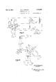
Fig. 1 is a diagrammatic view of the tuning fork driving circuits;
Fig. 2 shows the projector mechanism at the receiving station;
Figs. 3 and 4 show modified forms in which the mirrows are mounted on a string galvanometer or an oscillograph;
Fig. 5 represents a circuit in which a piezoelectric crystal vibratoris used to control the oscillator tube that governs the frequency of the tuning fork;
Fig. 6 shows schematically the arrangement of the analyzer at the transmitting station;
Fig. '7 is a diagram of the synchronizing circuits at the transmitting station;
Fig. 8 is a diagram of the synchronizing circuits at the receiving station;
Fig. 9 shows in a diagrammatic side view an arrangement adapted to secret television transmission;
Fig. 10 is a diagrammatic plan view of. the
same. i
The use of motor-driven analyzing and projecting television devices involves many mechanical difficulties inherent in the synchronizaticn of the motors at the sending and the receiving stations, which necessitates complicated apparatus and numerous circuits, as the synchronization must be practically perfect at all times to obtain satisfactory results.
In the present invention the analyzing unit at the transmitting station is essentially of the same general design as the projecting unit of the receiving station, as each includes two tuning forks driven at definite frequencies in planes at right angles'to each other, and with a mirror or other reflecting element on a prong of each so that light from one is reflected to and by the other.
Tuning fork 38, which is part of the receiving apparatus, has a right angled prism 37 secured to one prong, though this prism may be replaced by a mirror or other equivalent device. Adjustable loading screws 12 held fixed in place by lock nuts 13 are provided on the ends of the prongs to make it possible to vary the natural period of vibration of the fork. I
Tuning fork 38 is caused to vibrate by an electrc-magnet 14 disposed to act on one prong of the fork. The power for energizing the magnet is derived from the plate circuitof vacuum tube" 15, in which circuit the magnet is connected. Switch 16 is provided to cut off the current when desired. A second electro-magn et 17, connected in the grid circuit of tube 15, is placed adjacent to the other prong of the fork. When switch 16 is closed magnet 14 is energized and attracts the adjacent prong of fork 38, which causes the other prong to swing toward magnet 1'7, whichreduces the air gap of the latter magnet and increases the magnetic flux through it, thus inducing in the coils of magnet 17 a voltage that is impressed upon the grid of tube 15 and cuts down the current in the plate circuit. Diminution of the current through magnet 14 decreases its strength and the prong of the fork is released to move back, "as does the other prong also. The increased distance between magnet 1'7 and the prong of fork 10 augments the reluctance of the magnetic circuit and reduces the flux, so that a voltage is set up in the coils of magnet 1'7, which, being impressedon the grid, reduces the negative potential thereof and permits an increased flow of current in the plate circuit that passes through magnet 14 and again attracts the prong adjacent thereto; Magnet '14 may conveniently be called the driver magnet and magnet 1'7 may be called the grid control magnet.
The vibration of fork 38 may be varied to get it into step with the fork of like frequency in the transmitter by means of a magnet 18 placed between the prongs of the fork, and energized from plate battery 19. In the circuit of this magnet is a vibratile reed 20 that may be periodically moved against contact 21 by the teeth on a starwheel 22 operable manually by a crank 23. The current strength in this circuit may be regulated by variable resistance 24 or by changing the connection of this circuit to battery 19. Periodic energize.- tion of magnet 18 by the alternate opening and closing of the circuit by means of reed 20 will affect the vibration'o'f fork 38, and it may thus be caused to vibrate in exact harmony with the other forks of its frequency in the system. This device 18202l-22-2324, etc., is further used .to start the fork vibrating in case the type of driving circuit used is such that self-starting (or fork vibrations) feature is not incorporated.
The analyzer at the transmitting station is shown in Fig. 6. Light from::source:25.is concentrated on an aperture in screen 26 by lens 27, from whence it is directed upon prism 11 on fork 10, hereinafter called the high speed. fork,.by lens 32. Fork 10 is driven by a magnetlike Iiand actuates a grid control magnet like 17, above explained. Fromprism llthelightpasess toprism 28 on low speed fork 29, which is-driven by;magnet 30 and affects -grid-.control magnet. 31 as above described. The light .from prism 28 falls upon the object whereof. the representation. is to bev transmitted, in tthe-present instance shown as a photo film. 32, by way of example. The light from film .32- is focussed onaphoto-electric cell 33 by lens 34, the .currents from which are amplified for transmission byamplifier 35. In a modified form of .analyzer using the same apparatus in an inter changeable arrangement, the object to be televised is illuminated by a source of light external to the analyzer :and -the.light reflected by the object is Jeflected to'the prism' 28,:refracted to the prism 11 andiromprismll throughthelens 32 to a photo- ;electric-.ce1l;33 which will now-be .locatedin the position of the aperture in screen 26.
.Tuning;fork 10 is designed to have a natural frequency-of. 500, .750, 1.000, or 1500 vibrations per second, .as is foundmost suited .to the 'class of ,transmission-involved i. e., whether still pictures, moving pictures, or :moving rscene. Fork 29 may havea frequency of 8, 15,120.25, or30 vibrations per second. The variation .in .frequency allowableito both forks'willbe limitedtoa considerable .extentby the intensity ofthe-source of'light avail- -=able.
zForks 10 and ZQ-Vibrateinplanes atright angles ztoeach-other, the-movementof oneof them traversing the beam of light back and =forthin one direction over the subject-and theiother moving :thebeamatright angles theretosso thatthecombined:motions'scanathe entire surface. .It:is necessarynthatthe beam should coverthe surface'in .the period of the per-sistenceof the visualimage, that-isfrom-,one-sixteenth tonne-twentieth of a second-so thatthe eye will-perceive the pictureas :a wholeand.not'beawarebf the separatelines of which it-is composed. The light which reaches cell;33.- after:having-passed through the film 32 or -having :been reflected to Fit from the subject will be of .varying intensity, idepending'upon thedenjsity o'f'shadinglin t-he different parts-of the'film :or upon-theamount'ofilightreflected from differ- --ent parts of thersubject andwill result in the prolduction ofian.identically varying current from the cell, andthiscurrent, when passed through the ;projeotor -.at the receiving station, will reproduce -:on the-screenaat the receivingstationthe picture on film-32 or of the=subject.
The apparatus ,--at -the receiving station comiprisescan amplifier 34'through whichthe incoming ;current :from the transmitter is passed and :whichu's :connectedxto .a source-of light, shown for illustration in Fig. 2 as a neon tube 35, whereof the intensity is controlled by the current received from amplifier 34. The light from source 35 is focussed by lens 36 on prism 37 carried by a prong of high speed tuning fork 38, by which it is reflected to prism 39 on a prong of low speed fork 40, the beam from the latter prism passing through dispersing lens 41 and thence upon screen 42. Fork is driven by electro-magnet .42 and actuates a grid control magnet 43, as in the transmitting apparatus. It is to be understood that .fork 38 has a driving magnet and a grid control magnet associated therewith as be fore described. Forks 38 and 40 of the receiving chronism is obtained and the picture is sharp and distinct.
The circuits of the transmitting apparatus are shown in Fig. 7, with the forks omitted for sim-' plicity. The plate of vacuum tube 43 is connected todriver magnet 44 and the grid thereof is connected to grid control magnet 45 constituting the circuit for the-high speed fork. A filter circuitcomprising condensers 46,47 and 48, and:
said circuit also including driving magnet 54.-
The grid circuit of tube 52 includes the grid control magnet 55. The circuit of the low speed fork .is inductively coupled to the grid of the tube 56 at5'7,.the amplifier circuit having any desirable number of stages of. amplification, here represented'by the tube mentioned and tube 58 with the resistances 59 and 60 and condenser 61, the output from the amplifier being indicated'at 62. The
values of the inductances and capacities of the filter circuit are such that thecircuit of the low speed fork can influence the circuit ofthe high speed fork, but prevent the reverse operation. The purpose of this arrangement is to insure that atperiodic intervals, that is, each time the vibrations of the two forks are in phase, the vibrations of thelow speedfork can act upon the high speed fork to keepthe two forks relatively in step, as the vibration rate of the high speed fork is some definite number of times as great as that of the low speed fork.
The circuits at the receiving station are shown in Fig. 8. The impulses are received either by means of antenna 63 and the devices associated therewith, or from wire lines 64, depending upon the means selected for transmission. The signals are impressed through coupling 65 upon the amplifying circuits comprising tubes 66 and 67, resistances68 and 63, and condenser '70. The output of tube 67 is coupled at '71 to a filter comprising inductances '72 and 73, and condensers '74, '75, and 76. (This filter will'be omitted unless a synchronizing impulse is impressed on the transmitted wave by means of a transformer 77, as shown in Fig. 3. When the filter is omitted the low speed fork circuit is coupled to theamplifier at 71.)
The low'speed fork circuit is coupled to the filter circuit at 78. This circuit comprises vacuum tube .79, driving magnet 89 and-grid control .magnet 81.
A second filter circuit is coupled to the low speed fork circuit at 82, and consists of inductances 83 and 84, and condensers 85, 86, and 87. The purpose of this filter is the same as that of the filter between the two fork circuits at the transmitting station; viz., to permit the impulses in the low speed fork circuit toaffect the high speed fork circuit, but to prevent reciprocal action. The second filter is coupled to the cir- 'cuit of. the high speed fork at 88, the circuit of this fork including tube 89, driving magnet 90, and grid control magnet 91.
In the modified form disclosed in Figs. 3 and 4 the mirrors are mounted on the wires of string galvanometers disposed toact as an oscillograph, instead of on the prongs of tuning forks. The circuits of one fork and galvanometer are shown in Fig. 3 and the disposition of the two galvanometers is diagrammatically indicated in Fig. 4. The plate circuit of tube 92 includes inductive coupling member 93, inductive coupling member 94, and
, driving magnet 95 for a low speed fork, while the grid circuit thereof includes inductive coupling member 96 and grid control magnet 9'7. A tuning fork is driven by magnet 95 and varies the flux through magnet 9'7 as before explained, so that there is set up a periodic variation of the current in the plate circuit, which variation is impressed upon the suspension wires of mirror 98 between the poles of magnet 99 in a manner well known, through transformer 100 of which element 94 is a part. Light from source 101 is directed upon mirror 102 suspended between the poles of magnet 104 upon wires 103 by the lenses 105, 106, and 107, the vibrations of mirror 102 being controlled by a high speed fork connected thereto in the manner shown in Fig. 3 in connection with From mirror 102 the light is reflected to mirror 98 mounted on wires 108 in the field of magnet 99, and from the latter mirror the light passes to the subject whereof the representation is to be transmitted. At the receiving station the relations of the elements of the mechanism would be much the same, except that the light from the second mirror would go to the screen instead of to the subject.
Where a more exacting means of synchronizing is requisite or desirable, the device shown in Fig. 5 may be employed. In this instance the frequency of an oscillator tube 110 is accurately controlled by a piezo-electric crystal oscillator 111 connected tothe grid of the tube. Variable condenser 112 is connected across the terminals of the oscillator, and variable condenser 113 and inductance 114 connected in parallel with each other are in series with crystal oscillator 111. The plate of tube 110 is connected to the other common terminal of condenser 113 and inductance 114." The filament of tube 110 is connected to inductance 114 through condenser 115, and the grid of the tube is connected to the filament through resistance 116. The natural period of crystal oscillator 111 should be the same as that of the fork whereof the frequency is to be controlled thereby, and any minor variations therefrom may be controlled by variable condenser 112.
The tuning fork is driven by magnet 117 in the plate circuit of tube 118, the grid of tube 118 being coupled to inductance 114 by inductance 119 in the circuit of the grid. It will be seen that the oscillations of the crystal oscillator circuit will be impressed on the grid of tube 118, and the plate current of that tube will be controlled by such oscillations, and'hence the vibration of the fork driven by magnet 117 will be very accurately determined by the frequency of the crystal oscillator. This will give a control of the frequency of the fork to within two parts in 1,000,000, and when once adjusted to be in synchronism with a fork of like period in the transmitting station the two stations will be kept in step. 0
An arrangement whereby my invention may be used for secret transmission is shown in Figs. 9 and 10. It comprises two groups of reflecting prisms disposed in annular series in spaced planes, those of one group being designated 120, 121, 122, 123, 124, 125, 126, and 127, and those of the second group shown in Fig. 9 are designated by 122, and 126' to indicate that they coact with certain ones in the first group. A prism 128 mounted on one end of the shaft of selector motor129 is so disposed that the light refiected therefrom is received by a mirror of the first group with which it may be aligned, while a prism 130 on the other end of the same shaft receives the light reflected from one of the prisms of the second group and directs it upon the subject, here shown as a film 131, from which point the conversion of the light to a high frequency electric impulse is accomplished in the same way as set forth above. The light is initially supplied to prism 128 by means of a source 132 and lens 133. While eight prisms have been indicated in each group, the number may be varied as desired.
The mirror 128 is carried on a high speed fork and those in the first group; viz., 120-127, are on low speed forks, each of which vibrates at a different frequency from the others, and all of which vibrate in a plane at right angles to the plane of vibration of prism 128. The prisms of the second group are fixed and do not, vibrate.
The beam from the prismsof the first series to v those in the second will be vibrating in two planes atright angles to each other, and so will scan the subject when passed thereover.
The receiving station will include two like sets of prisms, with those occupying the same sequential position vibrating at the same rates as the prisms of the transmitting station, and the selector motor will be synchronized with that of the sending mechanism. In use, prism 128 may be aligned with prism 120 and prism with 120 and a word or section of a message, chart, map, picture, etc., will be sent on one low speed frequency from prism 120, then motor 129 will rotate to align prism 128 with prism 121, which is vibrat ing at a different frequency, and also align prism 130 with prism 121, and a second fragment will be sent, and so forth until the entire group of frequencies has been utilized, when the sequence is repeated. The apparatus may be adjusted that upon a second sequence a different interval will be consumed between each two of the several I prisms of the series, so that any one not having the same number of mirrors, in the same sequence,
and with the same time intervals elapsing between each two of the several prisms can not receive in intelligible form the subject that is being transmitted.
The selector motors can be synchronized by an initial radio impulse that will start a ohronometer, the selector shaft being in reality driven by an electric chronometer that serves as a selector motor.
It should be understood that the arrangement illustrated in Figures 9 and 10, wherein tuning forks are used for analyzingis simply illustrative and not restrictive, one object of my invention being to provide a systemof analyzing and projecting, using any of the'well-known means available such as moving coil galvanoineters or oscil- I lographs, vibrating reeds, cathode ray tubes, etc.,
wherein the analyzing in one direction is at definite frequency, while at the same time the analyzing in the seconddirectionis done at arapidly changing frequency, the frequency for any time interval being constant and definite, while during. theneXt time interval the frequency though constant and definite will be different from that of the previous and/or succeeding time intervals.
'It will be 'understoodthat the above description and accompanying drawings comprehend only the general and preferred embodiment of my invention, and that various changes in construction, proportion and arrangement of parts may be made Within the scope of the'app-ended claims, and without sacrificing any of the advantages of my invention.' 1
The herein describedinvention may be manufactured and used by or for the Government of the United States for governmental purposes without the payment to me of any royalties thereon.
Having thus described my invention, what I claim is: 1
1. In a television device, a source of light, a high speed tuning fork, a reflecting prism on a prong thereof disposed to receive light from said source, a vacuum tube, a driving electro-magnet connected in the plate circuit thereof and disposed to cause said fork to vibrate at its natural frequency, a grid control electro-magnet disposed adjacent a prong of said fork and connected in the grid circuit of said tube, whereby variation of flux in said second magnet caused by the movement of said prong will be impressed upon said grid, a second fork disposed to vibrate at a lower frequency than that of the first said fork in a plane at right angles to the plane of vibration of the first fork, a reflecting prism on a prong of said second fork disposed to receive light from the prism on the first said fork, a photo-electric cell, means to project the light from said second prism on a subject whereof a representation is to be transmitted and thence to said photo-electric cell, electric transmitting means connected to said cell to transmit energy having variation characteristics substantially identical with those of the current from said cell, means to receive the transmitted energy, an amplifying device connected to increase the energy so received, a second source of light whereof the intensity is varied by the received energy and proportionally to the variations of said energy, a second low speed fork vibrating at the same frequency as the aforesaid low speed fork, a vacuum tube, a driving magnet and a grid control magnet associated therewith as aforesaid, a reflecting prism on a prong of said second low speed fork disposed to receive light from said secondsource, a second high speed fork and a driving magnet and a grid control magnet associated therewith, a frequency third filter circuit coupled between the circuits 7 of the first high speed and low speed forks.
2. Ln a television device, a transmitting device comprising a source of light, a tuning fork adapted to vibrate in a plane at one speed, a second tuning fork adapted to vibrate in a plane at right angles to the said plane at a different speed, a refleeting device on a prong of each of the said forks so disposed that light from the one on the first fork is reflected to the oneon the second fork, a vacuum tube associated with each of said forks, means operable by the plate current of each fork to drive the respective fork, other means governed by the vibration of each fork'to control the plate current of the respective vacuum tube, a filter circuit coupled between the circuits of said tubes, a subject to be transmitted disposed to receive light from the reflecting device on said second tuning fork, a source of electric current controlled by the light from said subject, means to transmit energy varying inlike manner asthe current from said source, means to receive the a period of vibration the same as that of said second fork, a reflecting device on one prong thereof, a fourth fork vibrating in a plane at right angles to the plane of vibration of said second fork, means to drive each of said third and fourth forks at its natural frequency, means governed by the vibration of each of said third and fourth forks to control the plate current of the respective tube, a filter circuit between the circuits of the last mentioned tubes, a magnetic frequency control device operably related to each of the said forks and a manually rotatable star wheel operatively related to saidmagnetic control device to energize said device periodically.
3. In a television device, a source of light, means to cause a beam from said source to vibrate in a plane, means to cause said vibrating beam to vibrate in a plane transverse to the aforesaid plane, a vacuum tube operatively connected to each of said means to operate said means and to be reciprocally controlled by said means, a filter circuit between the circuits of said tubes, means to cause said vibrating light to vary to represent a subject to be transmitted, means to transmit energy varying in like manner as said light, means to receive said energy and to cause a beam of light to vary in like manner as said energy, means to cause said last mentioned beam of light to vibrate in a plane, other means to cause said last mentioned beam to vibrate in a plane transverse to the last mentioned plane, the last mentioned means and the next to last mentioned means having respectively the same vibrational rates as the first mentioned means and the second mentioned means, a vacuum tube operatively cenneetea to ash or the last mentioned star wheel operatively related to said magnetic means to energize said means periodically.
4. In a television device, a plurality of reflectin'g devices disposed in an annular series, a second annular series of reflecting devices equal in number to the first series and so disposed that each device in said second series may receive light reflected from the corresponding device in said first series, the devices in said first series being mounted to vibrate each at a difierent rate and each of them vibrating in a plane having the same relation to its respective radius as the others, a refleeting device rotatably mounted centrally of said first series to vibrate at a rate different from any of those in said first series and adapted to reflect light to the devices in said series seriatim and to vibrate in a plane transverse to the plane 7: of the device to which light is being reflected by it,
and a reflecting device centrally located within said second series adapted to receive light from that one of said second series to which light is being reflected by one of said devices in the first series, and to reflect again the light so received.
5. In a television device, a rotatable device including a shaft, a reflecting device mounted on said shaft to rotate therewith and to vibrate, a second reflecting device mounted on the other end of said shaft to rotate therewith, an annular series of reflecting devices mounted around said first mentioned reflecting device to receive light reflected therefrom at the proper point in the rotation of said first mentioned reflecting device and to vibrate in a plane transverse to the plane of vibration of said first mentioned reflecting device when receiving light therefrom, and a second annular series of reflecting devices so mounted that each receives light reflected from one of the devices in the first series and to reflect light so received to said second mentioned reflecting device which again reflects said light, the rate of vibration of each of said devices in the first series I being difierent from that of all the others in said l series and from that of the first mentioned reflecting device, and the rate of rotation of said rotatable device being variable during rotation.
6. In a television device, a series of reflecting devices mounted for vibration, each at a differ- 1 ent rate, a second series of reflecting devices so mounted that each one thereof receives light reflected from one of the devices in the said first series, a reflecting device mounted to be movable to receive light reflected from any one of I those in the second series, and means to transmit to the devices in the first series a light beam vibrating in a plane different from the plane of vibration of the device in the first series to which said light is going and at a rate different from the rate of the specified device, the said vibrating .i verse vibration of said vibrating beam, means to vary the frequency of said transverse vibration in a predetermined sequence not related to the subject being transmitted, and means to vary said sequence each said rate of vibration in the sequence being maintained constant for a predetermined time interval which may differ in duration from the duration of any other rate.
8. In a television device, a source of radiant energy, means to cause a beam of said energy to vibrate in a plane, means to cause said vibrating beam to vibrate in a plane transverse to the aforesaid plane, means to control the period of frequency of transverse vibration of said vibrating beam, means to vary the frequency of said transverse vibration in a predetermined sequence not related to the subject being transmitted, and means to vary said sequence each said rate of vibration in the sequence being maintained constant for a predetermined time interval which may differ in duration'from the duration of any other rate.
9. In apparatus of the class described a rotatable reflecting device mounted to vibrate in a plane parallel to its axis of rotation, a pluraltatable reflecting device mounted to vibrate in a plane parallel to its axis of rotation, a plurality of reflecting devices mounted to vibrate in planes transverse to the plane of vibration of said rotatable reflecting device and to receive in turn light from said rotatable reflecting device, and means to direct light received by any one of said plurality of devices from said rotatable reflecting device to a common receiving element.
11. A television system comprising a transmitting and a receiving mechanism, each of said mechanisms comprising a high speed tuning fork disposed to vibrate in a plane and a low speed fork disposed to vibrate in a plane transverse to the aforesaid plane, a reflecting device on each high speed fork disposed to direct light to a reflecting device on the adjacent low speed fork,
means to actuate each of said forks, means to impress the frequency of each low speed fork upon the adjacent high speed fork, magnetic synchronizing means operatively associated with each of said low speed forks and a manually rotatable star wheel operatively related to said synchronizing means to energize said synchronizing means periodically.
12. In a television device, a reflecting surface, means for causing said reflecting surface to vibrate, a second vibrating surface operatively positioned with respect to said first reflecting surface, means to cause said second reflecting surface to vibrate, and means to vary periodically the rate of vibration of said second reflecting surface in accordance with a pre-determined sequence not related to the subject being transmitted and to vary said sequence each said rate of vibration in the sequence being maintained constant for a predetermined time interval which may difier in duration from the duration of any other rate.
13. In a device of the class described, a tuning fork, a light reflecting device carried by a prong thereof, a vacuum tube, an electromagnet connected to the plate of said tube to be energized tromagnet to energize said third electromagnet periodically.
14. In combination, a tuning fork, an electromagnet disposed to cause the prongs of said fork to vibrate, a second electromagnet disposed between the prongs of said fork adapted to be energized to change temporarily the frequency of said fork and means including a manually rotatable star wheel to energize said second electromagnet periodically.
WILLIAM H. SWEENEY.
Priority Applications (1)
| Application Number | Priority Date | Filing Date | Title |
|---|---|---|---|
| US569763A US1979296A (en) | 1931-10-19 | 1931-10-19 | Television apparatus |
Applications Claiming Priority (1)
| Application Number | Priority Date | Filing Date | Title |
|---|---|---|---|
| US569763A US1979296A (en) | 1931-10-19 | 1931-10-19 | Television apparatus |
Publications (1)
| Publication Number | Publication Date |
|---|---|
| US1979296A true US1979296A (en) | 1934-11-06 |
Family
ID=24276754
Family Applications (1)
| Application Number | Title | Priority Date | Filing Date |
|---|---|---|---|
| US569763A Expired - Lifetime US1979296A (en) | 1931-10-19 | 1931-10-19 | Television apparatus |
Country Status (1)
| Country | Link |
|---|---|
| US (1) | US1979296A (en) |
Cited By (11)
| Publication number | Priority date | Publication date | Assignee | Title |
|---|---|---|---|---|
| US2531974A (en) * | 1949-04-07 | 1950-11-28 | Zenith Radio Corp | Subscription type television transmitter |
| US2730670A (en) * | 1949-11-14 | 1956-01-10 | Asea Ab | Means for producing low-frequency electrical oscillations |
| US3152307A (en) * | 1960-01-25 | 1964-10-06 | Phillips Petroleum Co | Tuning fork frequency generator |
| US3447853A (en) * | 1965-07-30 | 1969-06-03 | Rca Corp | Light deflecting apparatus |
| US3520586A (en) * | 1966-06-20 | 1970-07-14 | Ampex | Entrant beam optical scanner |
| US3725817A (en) * | 1964-09-02 | 1973-04-03 | Rca Corp | High power laser system |
| US3805190A (en) * | 1972-10-09 | 1974-04-16 | G Berlin | Photoelectric device for generating and filtering low-frequency harmonic oscillations |
| US4902083A (en) * | 1988-05-31 | 1990-02-20 | Reflection Technology, Inc. | Low vibration resonant scanning unit for miniature optical display apparatus |
| US5003300A (en) * | 1987-07-27 | 1991-03-26 | Reflection Technology, Inc. | Head mounted display for miniature video display system |
| US5023905A (en) * | 1988-07-25 | 1991-06-11 | Reflection Technology, Inc. | Pocket data receiver with full page visual display |
| US5048077A (en) * | 1988-07-25 | 1991-09-10 | Reflection Technology, Inc. | Telephone handset with full-page visual display |
-
1931
- 1931-10-19 US US569763A patent/US1979296A/en not_active Expired - Lifetime
Cited By (11)
| Publication number | Priority date | Publication date | Assignee | Title |
|---|---|---|---|---|
| US2531974A (en) * | 1949-04-07 | 1950-11-28 | Zenith Radio Corp | Subscription type television transmitter |
| US2730670A (en) * | 1949-11-14 | 1956-01-10 | Asea Ab | Means for producing low-frequency electrical oscillations |
| US3152307A (en) * | 1960-01-25 | 1964-10-06 | Phillips Petroleum Co | Tuning fork frequency generator |
| US3725817A (en) * | 1964-09-02 | 1973-04-03 | Rca Corp | High power laser system |
| US3447853A (en) * | 1965-07-30 | 1969-06-03 | Rca Corp | Light deflecting apparatus |
| US3520586A (en) * | 1966-06-20 | 1970-07-14 | Ampex | Entrant beam optical scanner |
| US3805190A (en) * | 1972-10-09 | 1974-04-16 | G Berlin | Photoelectric device for generating and filtering low-frequency harmonic oscillations |
| US5003300A (en) * | 1987-07-27 | 1991-03-26 | Reflection Technology, Inc. | Head mounted display for miniature video display system |
| US4902083A (en) * | 1988-05-31 | 1990-02-20 | Reflection Technology, Inc. | Low vibration resonant scanning unit for miniature optical display apparatus |
| US5023905A (en) * | 1988-07-25 | 1991-06-11 | Reflection Technology, Inc. | Pocket data receiver with full page visual display |
| US5048077A (en) * | 1988-07-25 | 1991-09-10 | Reflection Technology, Inc. | Telephone handset with full-page visual display |
Similar Documents
| Publication | Publication Date | Title |
|---|---|---|
| US1979296A (en) | Television apparatus | |
| US1779748A (en) | High-speed television system | |
| US2072419A (en) | Television method and apparatus | |
| US2528924A (en) | Vassy | |
| US2578939A (en) | Telemetering | |
| US1789521A (en) | Television system | |
| US1966354A (en) | High speed telegraph system | |
| US1725710A (en) | System and method obi television | |
| US2059221A (en) | Television system | |
| US2247051A (en) | Method and apparatus for television | |
| US2090853A (en) | Radiant energy resonant vibratory system | |
| US1874200A (en) | Electrooptical image producing system | |
| US2202541A (en) | Television and like system | |
| US1839706A (en) | Electrotelescopy | |
| US2234919A (en) | Facsimile synchronizing system | |
| US1768634A (en) | Means for electrically transmitting imagery | |
| US1958606A (en) | Television method and apparatus | |
| US1694301A (en) | Electrical transmission of pictures | |
| US1605930A (en) | Television system | |
| US1955320A (en) | Television synchronization method | |
| US2143093A (en) | Wave generator | |
| US1602121A (en) | Television | |
| US2163749A (en) | Radial scanning television system | |
| US1773981A (en) | Television receiving system | |
| US2290823A (en) | Double carrier facsimile |