US1856531A - Latch for baling press doors - Google Patents
Latch for baling press doors Download PDFInfo
- Publication number
- US1856531A US1856531A US40350329A US1856531A US 1856531 A US1856531 A US 1856531A US 40350329 A US40350329 A US 40350329A US 1856531 A US1856531 A US 1856531A
- Authority
- US
- United States
- Prior art keywords
- door
- baling
- latch
- bale
- baling press
- Prior art date
- Legal status (The legal status is an assumption and is not a legal conclusion. Google has not performed a legal analysis and makes no representation as to the accuracy of the status listed.)
- Expired - Lifetime
Links
Images
Classifications
-
- B—PERFORMING OPERATIONS; TRANSPORTING
- B30—PRESSES
- B30B—PRESSES IN GENERAL
- B30B9/00—Presses specially adapted for particular purposes
- B30B9/30—Presses specially adapted for particular purposes for baling; Compression boxes therefor
- B30B9/3003—Details
- B30B9/3032—Press boxes
-
- Y—GENERAL TAGGING OF NEW TECHNOLOGICAL DEVELOPMENTS; GENERAL TAGGING OF CROSS-SECTIONAL TECHNOLOGIES SPANNING OVER SEVERAL SECTIONS OF THE IPC; TECHNICAL SUBJECTS COVERED BY FORMER USPC CROSS-REFERENCE ART COLLECTIONS [XRACs] AND DIGESTS
- Y10—TECHNICAL SUBJECTS COVERED BY FORMER USPC
- Y10T—TECHNICAL SUBJECTS COVERED BY FORMER US CLASSIFICATION
- Y10T292/00—Closure fasteners
- Y10T292/08—Bolts
- Y10T292/0801—Multiple
- Y10T292/0834—Sliding
- Y10T292/0836—Operating means
- Y10T292/084—Cam
-
- Y—GENERAL TAGGING OF NEW TECHNOLOGICAL DEVELOPMENTS; GENERAL TAGGING OF CROSS-SECTIONAL TECHNOLOGIES SPANNING OVER SEVERAL SECTIONS OF THE IPC; TECHNICAL SUBJECTS COVERED BY FORMER USPC CROSS-REFERENCE ART COLLECTIONS [XRACs] AND DIGESTS
- Y10—TECHNICAL SUBJECTS COVERED BY FORMER USPC
- Y10T—TECHNICAL SUBJECTS COVERED BY FORMER US CLASSIFICATION
- Y10T292/00—Closure fasteners
- Y10T292/08—Bolts
- Y10T292/0801—Multiple
- Y10T292/0834—Sliding
- Y10T292/0836—Operating means
- Y10T292/0844—Lever
Definitions
- My invention relates generally to flat news paper baling presses and'more particularly to a safety door therefor and the principal objects of my invention are, to provide a door forflat newspaper baling presses that will effectually prevent the stack of papers-that is being compressed within the baling press from bursting out through the opening through which the papers are delivered into the baling chamber of the press, further, to
- one side of the chamber in which the bales are compressed is left open in order to permit the operator to pass the metal bands or tie wires around the bale while the same is under pressure and in these forms of presses there is more or less danger of injury to the operators as a result of the bundle of papers bursting outwardly through the opening While under a high degree of pressure and which action results from irregular piling of the newspapers that make up the bale.
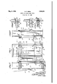
- FIG. 1 is'a front elevational view of a paper baling pressand showing my improved safety door in position thereupon.
- I Fig. 2 is a vertical section taken on the line 2-2 of Fig. 1. V
- Fig. 3 is a side elevational view of the frame of the baling machine and showing my improved door in position thereupon.
- Fig. 4 is a horizontal section taken on the line 4 el of Fig. 1.
- Fig.v 5 is a horizontal section similar to Fig. 4 and showing the latching bolts in withdrawn or retracted position soas to permitthe door to be opened.
- Fig. 6 is a vertical section taken on the line 66 of Fig. 4:.
- 10, 1O designate the side walls of the baling chamber, which walls are disposed to the sides of an opening 11, through which operate a pressure head 12, the latter being carried by a piston and said head and piston may be actuated by any suitable means, for instance, steam, compressed air or water.
- a fixed head 13 Connecting the upper portions of the side walls 10 is a fixed head 13 and formed in the underside of this fixed head and in the upper surface of the pressure head 12 are transversely disposed grooves or channels 14 for the accommodation of the metal bands or wires that are utilized for securing the bales that are compressed in the machine.
- Hinged on the rear upper portion of the baling machine is a counterbalanced gate or door 15 that is adapted to swing upwardly and outwardly so as to permit the compressed bales to be discharged from the baling chamber and when this door or gate is closed its lower end is secured by means of a manually operable do or latch 16 to a fixed cross bar 17.
- the sa ety door contemplated'by my invention is arranged so as to close the front side of the baling chamber and said door comprises upper, lower and intermediate cross rails or bars 18 and on the left-hand side of the door structure these bars or rails are connected to a vertically disposed rod 19 that serves as a hinge for the door and said rod is mounted in suitable anti-friction bearings 20 ghat are supported on fixed parts of the door rame.
- plates 23 Secured toand projecting outwardly from the right hand one of thefuprightside mem-- bers of the baling machine and in the same horizontal planes with the rails or bars 18 are plates 23, in which are formed apertures 2 l'an'd these platesserve as keepers for the latching bolts that are carried by the bars or rails 18; v
- intermediate one of the bars 1 8 is an outwardlyprojecting handle 27;
- the pressure head 12 is'now caused to move upwardly, thereby compressing, the bale of paperswithin the upper portion of the bailing chamber behind door or gate 15 andwhon said bale is compressed to the desired degree, the operator, positioned directly in front of the safety door, mayoinsert the bailing straps or wires through the grooves 14: in the fixed and movable heads of the press and unite the ends of said bailing straps or wires in'the usual manner while the bale is under compression;
- head 12 is lowered a shortdistance and door or gate 15 is released and swung upwardly in order to erinnit the removal of the bajleffrom th rb i g chamber," a e
- handle-27 is swung t'0- ward the right hand, thereby rocking sh'aft 26 and swinging arms 29ftoward' the left hand, thereby withdrawing the'latchingbolts 28 from the keepersf23; 1, V
- a latch comprising a plurality of hora izontally disposed tubular members arranged on the outer face of the door, a-pair oflatching bolts arranged for sliding movement" in the end of each tubular member, a vertically dis; posed shaft ouranled in bearings on said tu bular members, a handle for actuating said shaft, arms'projecting inwardly from said shaft above-and below said tubu'larmembers, pins seated in the latching :bolts-andproject ing through longitudinally disposed slots in the tubular members and said'armsfprovided with slotsfor the reception of the ends of saidpinsr H 17f 1 2.
- a latch comprising a plurality of horizontally disposed tubular-members are ranged n th u r f ce of the door, a pair of a ching bol s a anged for liding move ment i eend ofelac'h tubula memb er, fixed
Description
y 1932- M. F. BERG LATCH FQR BALING PRESS DOORS Filed Oct. so. 1929 1 I. Ill/ll Patented May 3, 1932 PATENT OFFICE MORRIS F. BERG, OF LOS ANGELES, CALIFORNIA LATCH non BALING PRESS noons Application filed October 30, 1929. Serial No. 403,503.
My invention relates generally to flat news paper baling presses and'more particularly to a safety door therefor and the principal objects of my invention are, to provide a door forflat newspaper baling presses that will effectually prevent the stack of papers-that is being compressed within the baling press from bursting out through the opening through which the papers are delivered into the baling chamber of the press, further, to
provide a safety door that may be readily opened and closed during operation of the preSsandfurther, to provide a safety door that will permit metal bands or tie wires to be placed around the bale of paper within the. press while the door is closed.
In certain types of fiat newspaper baling presses now in general use one side of the chamber in which the bales are compressed is left open in order to permit the operator to pass the metal bands or tie wires around the bale while the same is under pressure and in these forms of presses there is more or less danger of injury to the operators as a result of the bundle of papers bursting outwardly through the opening While under a high degree of pressure and which action results from irregular piling of the newspapers that make up the bale.
. It is one of the principal objects of my invention, to provide a door for newspaper baling presses that may be readily manipulated to permit a bale to be inserted and to provide means for locking the door when closed and thus the operator may, without danger of injury resulting from the bursting of the bale, place the metalbands or tie wires around the bale to confine the same when said bale has been compressed to the desired degree. v v
With the foregoing and other objects in view, my invention consists in certain novel features of construction and arrangement of parts that will hereinafter be more fully described and claimed and illustrated in the accompanying drawings, in which:
I Fig. 1 is'a front elevational view of a paper baling pressand showing my improved safety door in position thereupon.
I Fig. 2 is a vertical section taken on the line 2-2 of Fig. 1. V
Fig. 3 is a side elevational view of the frame of the baling machine and showing my improved door in position thereupon.
Fig. 4 is a horizontal section taken on the line 4 el of Fig. 1.
Fig.v 5 is a horizontal section similar to Fig. 4 and showing the latching bolts in withdrawn or retracted position soas to permitthe door to be opened.
Fig. 6 is a vertical section taken on the line 66 of Fig. 4:.
Referring by numerals to the accompanying drawings which illustrate a practical embodiment of my invention, 10, 1O designate the side walls of the baling chamber, which walls are disposed to the sides of an opening 11, through which operate a pressure head 12, the latter being carried by a piston and said head and piston may be actuated by any suitable means, for instance, steam, compressed air or water.
Connecting the upper portions of the side walls 10 is a fixed head 13 and formed in the underside of this fixed head and in the upper surface of the pressure head 12 are transversely disposed grooves or channels 14 for the accommodation of the metal bands or wires that are utilized for securing the bales that are compressed in the machine. Hinged on the rear upper portion of the baling machine is a counterbalanced gate or door 15 that is adapted to swing upwardly and outwardly so as to permit the compressed bales to be discharged from the baling chamber and when this door or gate is closed its lower end is secured by means of a manually operable do or latch 16 to a fixed cross bar 17.
The sa ety door contemplated'by my invention, is arranged so as to close the front side of the baling chamber and said door comprises upper, lower and intermediate cross rails or bars 18 and on the left-hand side of the door structure these bars or rails are connected to a vertically disposed rod 19 that serves as a hinge for the door and said rod is mounted in suitable anti-friction bearings 20 ghat are supported on fixed parts of the door rame.
Connecting the left hand portions of the rails 18 are upright bars or rails 21 and connecting the intermediate portions'of the upper and intermediate rails 18 and directly in front of the baling chamber are comparatlve- 11y heavy upright bars 22.
r These upright bars 22 are disposed so that they occupy positions between the grooves or channels 14 in'the fixed and movableheads 13 and 12, thus permitting the operator to readily position and manipulate the metal bands or wires that are applied to the bale for confining same in compreSSQd condition;
Secured toand projecting outwardly from the right hand one of thefuprightside mem-- bers of the baling machine and in the same horizontal planes with the rails or bars 18 are plates 23, in which are formed apertures 2 l'an'd these platesserve as keepers for the latching bolts that are carried by the bars or rails 18; v
J ournaled in bearings 25 that project outwardly from the right hand portions of'the beams or rails 18 is an upright-shaft 26 and secured to "the intermediate portion thereof,
' just above the; intermediate one of the bars 1 8 is an outwardlyprojecting handle 27;
I Arranged for slidingmovement in the ends of'the beams or bars 18 are latched members veach pair of latch bolts28 is a vertically disposed pin '30 that passesfthrough longitudinally disposed slots :31 thatare formed in the upper and lower walls of the beam or bar 18 and said pins also pass through short slots 32 that are formed in theinner ends of the crank arms 29 and which last mentioned slots are radially disposed relativeto the axis of the shaft 26. I In-the operation of my improved safety door the same is swung into full open position and'a stack of papersis'now deliveredinto the pressure chamber above head 12 and which latter is at its lower limit of movement, as illustrated in Fig. 2-; V
The door is now swung into closed position and handle 27 is swung toward the lefthand, thereby partially rotating shaft 26 and swingingthe crank arms 29 outwardly toward the ends of the bars 18. This action moves the pins 30 lengthwise through the 7 slots 31 and radially through the slots 32 and the forward or outer ends of the latching bolts 28 will pass through the apertures 24: in the keepers 28, thereby securely latching the door in closed position. a
The pressure head 12 is'now caused to move upwardly, thereby compressing, the bale of paperswithin the upper portion of the bailing chamber behind door or gate 15 andwhon said bale is compressed to the desired degree, the operator, positioned directly in front of the safety door, mayoinsert the bailing straps or wires through the grooves 14: in the fixed and movable heads of the press and unite the ends of said bailing straps or wires in'the usual manner while the bale is under compression;
During this'operation the operator is protested against injury as a result of the bale bursting whileunder-relatively high pres- 7 sure. 7
r-Alfterthebaling straps or wires have been properly applied to the bale, head 12 is lowered a shortdistance and door or gate 15 is released and swung upwardly in order to erinnit the removal of the bajleffrom th rb i g chamber," a e Toopen the safety door'so as to permit a subsequent stack of papers to be positionedin the baling chamber, handle-27 is swung t'0- ward the right hand, thereby rocking sh'aft 26 and swinging arms 29ftoward' the left hand, thereby withdrawing the'latchingbolts 28 from the keepersf23; 1, V
Thus it will be seen that I have provided a safety door for paper baling machines-that is relatively simple in construction, inexpensive of manufacture, capable of f being readily swung from one'position [to another and which door affords a maximum degree of protection to the operator while the baleis being compressedand while thebaling straps or wires are being placed around thescom- P s l I .L. w It will be understood that minor changes in the size, form and construction of; the various parts of -my improved safety'do'or for. paper baling machines may be made and substitut'ed for those herein'shown and'd'escribed without departing from the spirit of'myinvention, the ,scopelof which is set forth in the ap.- pended claims. v I'claim as my inventi'onz; j; 7 1. In a safety door for "paper baling presses,'a latch comprising a plurality of hora izontally disposed tubular members arranged on the outer face of the door, a-pair oflatching bolts arranged for sliding movement" in the end of each tubular member, a vertically dis; posed shaft ouranled in bearings on said tu bular members, a handle for actuating said shaft, arms'projecting inwardly from said shaft above-and below said tubu'larmembers, pins seated in the latching :bolts-andproject ing through longitudinally disposed slots in the tubular members and said'armsfprovided with slotsfor the reception of the ends of saidpinsr H 17f 1 2. In a safety-door1-forz paper baling presses,'a latch comprising a plurality of horizontally disposed tubular-members are ranged n th u r f ce of the door, a pair of a ching bol s a anged for liding move ment i eend ofelac'h tubula memb er, fixed
Priority Applications (1)
| Application Number | Priority Date | Filing Date | Title |
|---|---|---|---|
| US40350329 US1856531A (en) | 1929-10-30 | 1929-10-30 | Latch for baling press doors |
Applications Claiming Priority (1)
| Application Number | Priority Date | Filing Date | Title |
|---|---|---|---|
| US40350329 US1856531A (en) | 1929-10-30 | 1929-10-30 | Latch for baling press doors |
Publications (1)
| Publication Number | Publication Date |
|---|---|
| US1856531A true US1856531A (en) | 1932-05-03 |
Family
ID=23596018
Family Applications (1)
| Application Number | Title | Priority Date | Filing Date |
|---|---|---|---|
| US40350329 Expired - Lifetime US1856531A (en) | 1929-10-30 | 1929-10-30 | Latch for baling press doors |
Country Status (1)
| Country | Link |
|---|---|
| US (1) | US1856531A (en) |
Cited By (9)
| Publication number | Priority date | Publication date | Assignee | Title |
|---|---|---|---|---|
| US2631052A (en) * | 1949-10-12 | 1953-03-10 | Jamison Cold Storage Door Co | Latching and releasing mechanism for refrigerator doors |
| US3728959A (en) * | 1970-10-27 | 1973-04-24 | W Fredrickson | Baler |
| USRE28748E (en) * | 1970-10-27 | 1976-03-30 | Muncher Corporation | Baler |
| US5046767A (en) * | 1989-12-13 | 1991-09-10 | Jubbu Designer's Inc. | Convertible top latching mechanism |
| US5624149A (en) * | 1992-09-04 | 1997-04-29 | Asc Incorporated | Apparatus and method for securing a convertible roof to an automotive vehicle |
| US5755467A (en) * | 1995-01-31 | 1998-05-26 | Asc Incorporated | Latching and switch operating system for a convertible roof |
| US6042174A (en) * | 1997-08-22 | 2000-03-28 | Asc Incorporated | Latching and control apparatus for an automotive vehicle convertible roof |
| US20050200158A1 (en) * | 2004-03-12 | 2005-09-15 | Willard Michael T. | Convertible hardtop roof |
| US20050285410A1 (en) * | 2002-11-14 | 2005-12-29 | Doncov Stephen A | Convertible top latch |
-
1929
- 1929-10-30 US US40350329 patent/US1856531A/en not_active Expired - Lifetime
Cited By (14)
| Publication number | Priority date | Publication date | Assignee | Title |
|---|---|---|---|---|
| US2631052A (en) * | 1949-10-12 | 1953-03-10 | Jamison Cold Storage Door Co | Latching and releasing mechanism for refrigerator doors |
| US3728959A (en) * | 1970-10-27 | 1973-04-24 | W Fredrickson | Baler |
| USRE28748E (en) * | 1970-10-27 | 1976-03-30 | Muncher Corporation | Baler |
| US5046767A (en) * | 1989-12-13 | 1991-09-10 | Jubbu Designer's Inc. | Convertible top latching mechanism |
| US5772275A (en) * | 1992-09-04 | 1998-06-30 | Asc Incorporated | Apparatus and method for securing a convertible roof to an automobile vehicle |
| US5624149A (en) * | 1992-09-04 | 1997-04-29 | Asc Incorporated | Apparatus and method for securing a convertible roof to an automotive vehicle |
| US5678881A (en) * | 1992-09-04 | 1997-10-21 | Asc Incorporated | Apparatus and method for securing a convertible roof to an automotive vehicle |
| US5755467A (en) * | 1995-01-31 | 1998-05-26 | Asc Incorporated | Latching and switch operating system for a convertible roof |
| US6042174A (en) * | 1997-08-22 | 2000-03-28 | Asc Incorporated | Latching and control apparatus for an automotive vehicle convertible roof |
| US20050285410A1 (en) * | 2002-11-14 | 2005-12-29 | Doncov Stephen A | Convertible top latch |
| US7021696B2 (en) | 2002-11-14 | 2006-04-04 | Asc Incorporated | Convertible top latch |
| US7226110B2 (en) | 2002-11-14 | 2007-06-05 | Asc Incorporated | Convertible top latch |
| US20050200158A1 (en) * | 2004-03-12 | 2005-09-15 | Willard Michael T. | Convertible hardtop roof |
| US7063371B2 (en) | 2004-03-12 | 2006-06-20 | Asc Incorporated | Convertible hardtop roof |
Similar Documents
| Publication | Publication Date | Title |
|---|---|---|
| US1856531A (en) | Latch for baling press doors | |
| US3910181A (en) | Baling press | |
| US5575199A (en) | Compactor | |
| US4182236A (en) | Vertical baler with improved material hold-down and bale ejecting means | |
| US3469530A (en) | Rubbish baling apparatus | |
| US2863580A (en) | Refuse collection apparatus | |
| US2590649A (en) | Bale ejector | |
| DE1579117A1 (en) | Equipment for the production of rubber articles | |
| US3548744A (en) | Press box with improved door arrangement | |
| US1707314A (en) | Baling or bundling press | |
| DE1926292A1 (en) | Device for tying bales | |
| EP3750702A1 (en) | Container with a compressor unit | |
| US711353A (en) | Compress for cotton. | |
| US2337705A (en) | Door arrangement for baling presses | |
| DE1200258B (en) | Frame filter press | |
| US2690115A (en) | Apparatus for controlling rolling bales | |
| EP1171283B1 (en) | Baling press comprising a tiltable compacting container, and method for operating the same | |
| US500238A (en) | Cotton-press | |
| US984717A (en) | Baling-press. | |
| US522220A (en) | Cotton-press | |
| DE655905C (en) | Sand blow molding machine | |
| US304849A (en) | Combined lint-room and press | |
| DE2324777A1 (en) | DEVICE FOR COMPRESSING AND PACKING WASTE | |
| US1845148A (en) | Cotton press centering and retaining device | |
| US862036A (en) | Hay-press. |