US1854058A - Control head - Google Patents
Control head Download PDFInfo
- Publication number
- US1854058A US1854058A US474819A US47481930A US1854058A US 1854058 A US1854058 A US 1854058A US 474819 A US474819 A US 474819A US 47481930 A US47481930 A US 47481930A US 1854058 A US1854058 A US 1854058A
- Authority
- US
- United States
- Prior art keywords
- ram
- sealing
- rams
- piston
- chamber
- Prior art date
- Legal status (The legal status is an assumption and is not a legal conclusion. Google has not performed a legal analysis and makes no representation as to the accuracy of the status listed.)
- Expired - Lifetime
Links
Images

Classifications
-
- E—FIXED CONSTRUCTIONS
- E21—EARTH DRILLING; MINING
- E21B—EARTH DRILLING, e.g. DEEP DRILLING; OBTAINING OIL, GAS, WATER, SOLUBLE OR MELTABLE MATERIALS OR A SLURRY OF MINERALS FROM WELLS
- E21B33/00—Sealing or packing boreholes or wells
- E21B33/02—Surface sealing or packing
- E21B33/03—Well heads; Setting-up thereof
- E21B33/06—Blow-out preventers, i.e. apparatus closing around a drill pipe, e.g. annular blow-out preventers
- E21B33/061—Ram-type blow-out preventers, e.g. with pivoting rams
- E21B33/062—Ram-type blow-out preventers, e.g. with pivoting rams with sliding rams
Definitions
- This invention relates to what is lmown in the oil fields as a tubing control head and co-pending application, Serial No. 319,865,
- control heads there are two of these control heads employed, one control head being secured to the upper end of the well casing and the second controlhead being spaced from and supported above the first control head by a nipple which forms a continuation of the well caslng.
- Each control head comprises at, least onev pair of sealing elements which are disposed in diametrically opposed relation to each other and movable in opposite directionstransversely of the well casing.
- the sealing elements are adapted to have their opposed inner faces broughtinto sealing contact with each other, the said opposed inner faces of the respective sealing elements being grooved to receive and contact with the outer surface of a string of tubing, drill stem, or other device being run into, or moved longitudinally of, the well casing, to prevent the escape of fluid from the well casing around the string of tubing, etc.
- the sealing elements of one of the control heads are-drawn away from the tubing to permit the passage of a coupling, or other protuberancein the string of tubing, to pass through the said control head, the sealing elements of the other control head being maintained in sealing contact with each other and with the string of tubing while the coupling, etc. is passing through the first mentioned control head.
- the pressure of the gas or other fiuid in the well is sufliciently high to render the control heads practically inoperative, the pressure exerted against and between the opposed inner ends of the sealing elements being so great as to make it impossible to move the sealing elements toward each other and into sealing contact with each other and with the string of tubing, thus preventing the running of the tubing into the well to draw out the oil.
- the above mentioned condition is obviated by the provision of a by-pass which conducts the high pressure fluid from the well casing, below the sealing elements of the control head, to the rear or outer ends of the chambers in which the sealing elements are longitudinally movable, the object being to equalize the pressure at both ends of each of the sealing elements, so that the sealing elements can be readily moved, by manually operable means or by low powered mechanical means supplied for the purpose.
- the provision of the pressure equalizing means has resulted in a more efiicient oper ation of the control heads, at ordinary pressures and with wells containing fluids'under to the fact that, although the pressure is equalized at the opposite ends of each of,
- the object of the present invention is to provide means by which the difference in the effective areas of the opposite ends of each ram may be corrected, or compensated for,
- I provide a by-pass forconducting the gas from the well casing to the rearend of each of the chambers in which the rams are mount ed, in the samegeneral manner as disclosed in the said co-pending application, and in addition thereto I provide a by-pass affording communication between the rear end of each ram chamber and the rear end of the auxiliary cylinder associated therewith, so that the pressure in the said rear end of the auxiliary cylinder, behind the piston therein, will be the same as the pressure in the rear end of the ram chamber, behind theram therein.
- the diameterof the auxiliary cylinder and its piston may be such as to provide an effec tive area, which, when added to-the effective area of the rear end of the sealing ram will substantially equalize the effective area of' the front end of the sealing ram, thereby equalizing the opposing forces acting upon the opposite ends of-the ram, so that the ram may be readily moved forward into the sealing position by the operating mechanism regardless of the pressure of the gas in the well, however high it may be.
- each sleeve is substantially equal to thediameter of the bore of the cylinder, while the inner diameters of the linings may be of any'desired diameters.
- Fig. 2 is a section Fig. 1.; and Y I Fig. 3 illustrates an alternate form of the invention.
- a Fig. 1 is a longitudinal sectional elevation
- the upper portion of a wellvcasing is illustrated at 1, on which the lower control head 2 is located, the upper control head 2a being. disposed above the lower head 2 and connected thereto by a nipple 111.
- Each of the control heads comprises a vertical extending hollow cylindrical body portion 3, the bore 4 of which is axially alined ,Withthe well casing 1, the said bore being threaded to receive corresponding threads on the casing l and nipple 1a.
- Each control head in the present-instance,
- each of the lateral'extensions 5 is formed a suitable ram chamber 6 which, at its forward end, communicates directly with the central bore 4 of the body portion 3 of the control head.
- each of the ram chambers 6 is of a cylindrical form, disposedwith its axis extending radially from the vertically disposed axis ofthe central bore 4: of the body portion 3 of the control head.
- each of the cylindricalram chambers 6 Suitably mounted within each of the cylindricalram chambers 6 is a longitudinal movable sealing. jaw or ram 7, the said sealing rams7, 7 being located at oppositesides of the center of the central bore 4, and movable in opposite directions toward and away from each other within their respective chambers 6.
- the outer ends of the chambers 6 are respectiv'ely closed by removable closure heads
- each of the closure heads 8 constitutes a flanged integral head closing one end of an auxiliary cylinder 50.
- Each cylinder 50 has a bore 51 which extends inwardly from the opposite open flanged end 52 thereof to the said integral head8 at the closed flanged end of the cylin der.
- each of the auxiliary cylinders 50' is closed by a removable closure head 9, which is rovided with an elongated bearing 10 in w ich is slidably mounted a ram rod 11.
- the ram rod 11 projects from the rear end of the sealing ram 7, through the closure head 8 and the associated auxiliary cylinder 50,
- each of the ramrods 11 is provided with a series of gear teeth 13, which are adapted to mesh with gear teeth 14 formed on a'gear segment 15.
- the gear .segment 15 ' is pivotally mounted on a short shaft or stud 16 carried by lugs 17 formed on the bearinglO.
- Each of the gear segments 15 is provided with a socket 19 adapted to receive a suitable handle 20, which constitutes levers by which the segments 15 may be turned about their pivots, to move the sealing rams 7, 7 toward and away from each other, as above noted.
- each o'f'the bearings 10 is internally threaded as at 21. These threads 21 areadapted to receive corresponding external threads formed on jack screws 22, 22.
- each jack screw 22 is axially aligned with the ram rods 11, 11, as shown in the drawings, and each jack screw 22 is provided on its outer end with a suitable spider or wheel 23, having radially extending arms 24 provided with sockets 26 adaptedto receive a handle similar to the handle 20, whereby considerable leverage. may be obtained to force the sealing rams into sealing contactscrews 22 may be caused to follow the tail ends of the respective ram rods 11, when the sealing rams 7 are being moved by the levers 20, and when the gas pressure is not exceptionally high in the well casing 1.
- lever handles When high gas pressure is encountered suitable lever handles may be applied to the sockets 26 of the spider 23 for supplying additional leverage for turning the jack screws 22, which, together with the operation of the handles 20 of the gear segments 15, will move the sealing aws 7 in opposition to the high pressure existing in the well casing.
- the ram rods 11, 11 are provided with pistons which are located in the auxiliary cylinders 50, 50 respectively', and the fluid pressure is admitted from the well casing 1 to the rear ends of the ram chambers 6, 6 and to the rear ends of the aux.- iliary cylinders 50, 50 respectively.
- the fluid is conveyed by a suitable by-pass comprising a pipe 30 which is tapped into the body 3 of the control head 2 below the proj ections 5 thereon and communicates with the central bore 4 thereof.
- a suitable valve 31 The flow of pressure from the bore 1 to the pipe 30 is controlled by a suitable valve 31.
- the pipe 30 is provided with Y-fittings 32, 32 into one leg of each of whichis fitted a pipe 33. .
- the opposite end of each pipe 33 is tapped into an opening 34 formed in the head 8, which communicates withthe rear end of the ram chamber6, behind the ram 7 situated therein.
- each Y-fitting 32 In the third leg of each Y-fitting 32 is threaded apipe 35, on the outer end of which is mounted a Y-fitting 36.
- a pipe 35 In one leg of the site end of the pipe 37 is threaded into an aperture 38 formed in the head 9 of the auxiliary cylinder 50, affording communication to the rear end of the bore 51 of the auxiliary cylinder 50 at the rear side of the piston 60 located within the said auxiliary cylinder50.
- a suitable relief valve 39 by which, when the valve 31 is closed, the pressure may be relieved from the rear ends of the chambers 6 and cylinders 50.
- the forward end of the auxili'arycylinder '50 is provided with a pet cock 10 which func tions as a breather for the port-ion of the cylinder 50 between the forward end of the piston 60 and the rear end of the head 8.
- Vvhile the above described arrangement of the by-pass operates efliciently, when extremely high pressures are encountered, the pressure rushing upwardly between the opposed forward ends of the rams from the underside of the rams, as the rams start to move apart, has a tendency to loosen the packing in the front'ends of the rains 7, 7, and for this reason I employ means for equalizin the pressure above and below the rams in the ore 4 of the control head 2, as shown in Figs. 1 and 2, wherein a by-pass 130 is tapped at one end into the bore 4 of'the body 3 of the control head 2 at a point below the sealing rams 7,7 and is tapped at its opposite end into the bore 4 at a point above the sealing rams 7, 7.
- This by-pass is controlled by a valve 131 and is provided with a vent 139.v
- valve 131 when the valve 131 is opened as above noted, the pressure above, below and between the rams 7, 7, the pressure at the rear.
- each of the aux- ⁇ iliary cylinders 50 is an interchangeable sleeve or lining 65,-the outer diameter of which is substantially equal to the diameter of the bore 51 of the cylinder 50, in order to have the lining 65 fit snugly within the said bore
- the bore 66 of the lining-65 may be of any desired diameter, depending upon the result desired, and the piston on the ram rod 11 is adapted to be made with a diameter corresponding to the bore 66 of the lining 65 which is to be used.
- the lining 65 is provided with suitable threads 67 adjacent one of the sealing rams 7 a lining 65 is placed said rams to be readily moved by operation 52 thereof, whereby As above noted the front or sealingend of each of the sealing rams 7 has a greater effective area, against which the gas pressure operates, than has the rear end 7 5. of the said I ram, the diflerence in the areas of the two 70 faces being substantially equal to the crosssectional area of the ram rod 11.
- any of the well known means for detachably securing a piston to a piston rod may be employed for removably securing the pistons 60 to the ram rods 11 or the pistons may be permanently attached to the ram rods, and when a differently sized lining is to be used the ram rod may be detached from the rain 7 and. the entire ram rod 11 with the permanent piston therein may be replaced by a similar ram rod having a piston corresponding in diameter to the bore of the new lining to be used, the ram rod 1.1 being threaded into or otherwise secured in the ram 7 i v I claim:
- a control head forv well casings, having a passageway communicating with the well casing and a chamber extending laterally from and communicating with said passageway, a sealing element in said chamber adapted to have its front end projectedinto said passageway, a rod projecting through therearend of said sealing element, an auxiliary cylinder, a piston in said auxiliary cylinder and operatively connected to said rod, and means affording intercommunication between the rear ends of the chamber and auxiliary cylinder and between said rear ends and the well casing ,for conducting fluid from the well casing to the rear ends of the said chamber and the auxiliary cylinder equalizing the pressures in said rear ends behind the sealing element and piston with the pressure in the well casing and at the exposed end of the sealing element proj ecting into said passageway.
- a control head for well casings, having a passageway communicating with the well casing and a chamber extending laterally from and communicating with said passageway, a sealing element in said chamber have its front end projected into said passageway, a rod projecting through said chamber from the rear end of said sealing element, an auxiliary cylinder, a piston in said auxiliary cylinder and operatively connected to said rod, means afiordin-g intercommunication between the rear endsof the chamber and auxiliary cylinder and between ed to way,
- a control head for well casings, having a passageway communicating with the well casing and a chamber extending laterally from and communicating with said passageway, a sealing element in said chamber adapt have its front end projected into'said passageway, a rod projecting through said chamber from the rear end of said sealing element, an auxiliary cylinder, a piston in said auxiliary cylinder and operatively connected to said rod, means afiording intercommunication between the rear ends of the chamber and auxiliary cylinder and between said rear ends and the well casing for conducting fluid from the well casing to the rear ends of the said chamber and the auxiliary cylinder equalizing the pressures in said rear ends behind the sealing element and piston with the pressure in the well casing and at the exposed end of the sealing element projecting into said passageway, means for controlling the flow of fluid through the conducting for exhausting the fluid means, and means chamber and the casing and a chamber extending laterally from and communicating with said passagea sealing element in said chamber adapt- .ed to have its front end projected into said passageway, chamber from
- a control head for well casings, having a passageway communicating with the well casing and'a chamber extending laterally from and communicating with said passage- 20 passageway, a rod way, a sealing element in said chamber adapted to have its front end projected into said passageway, a rod projecting through said chamber from the rear end of said sealing element, an auxiliary cylinder, a piston in said auxiliary cylinder and operatively connected to said rod, and means for conducting fluid from the well casing to the rear ends of the said chamber and the auxiliary cylinder, the
- a control head for well casings, havlng a passageway communicating with the well casing and a chamberextending laterally from and communicating with said passageway, a sealing element in said chamber adapted to have its front end chamber-from the rear end of saidsealing element, an auxiliary cylinder, a piston in said auxiliarly cylinder and. operatively connected to said rod, means for conducting fluid from the well casing to the rear ends of the said chamber and the auxiliary cylinder, the
- a control head for well casings, having a passageway communicating with the well casing and I from and communicating with said passagea chamber extending laterally way, a sealing element in said chamber adaptprojected into said passageway, a rod projecting through said chamber from the rear end of said sealing auxiliary cylinder, a piston in said auxiliary cylinder and operatively connected to said rod, means for conducting fluid v T from the Well casing to the rear ends of the said chamber and the auxiliary cylinder, the
- a control head for well casings, comprising a body portion having a central bore substantially aligned with the bore of the Well casingand a chamber extending laterally from said central bore, a, sealing ram in said lateral chamber and adapted to have its forward end projected from the lateral chambcr across the said central bore, an auxiliary with said lateral chamber, a rod extending from the rear end of the sealing ram through the lateral chamber and the auxiliary cylinder, a piston "on the ram rod in said projected into said projecting through said auxiliary cylinder, and means affording lntercommunlcatlon be-
Description
H. C. OTIS CONTROL HEAD April 12, 1932 Filed Aug. 12, 1930 2 Sheets-Sheet April 12, 1932.
H. c. OTIS 1,854,058
CONTROL HEAD Filed Aug. 12, 1950. 2 Sheets-Sheet 2 .fir
v to
l atented Apr. 12, 1932 PATENT OFFICE UNITED STATES HERBERT C. OTIS, OF ,SHREVEPORT, LOUISIANA coNTRo'L HEAD Application filed August 12, 1930. Serial No. 474,819.
This invention relates to what is lmown in the oil fields as a tubing control head and co-pending application, Serial No. 319,865,
filed November 16, 1928. Devices of this character are adapted for use with oil wells in which gas or other fluid under high pressure is encountered. r c
Usually there are two of these control heads employed, one control head being secured to the upper end of the well casing and the second controlhead being spaced from and supported above the first control head by a nipple which forms a continuation of the well caslng.
. Each control head comprises at, least onev pair of sealing elements which are disposed in diametrically opposed relation to each other and movable in opposite directionstransversely of the well casing.
The sealing elements are adapted to have their opposed inner faces broughtinto sealing contact with each other, the said opposed inner faces of the respective sealing elements being grooved to receive and contact with the outer surface of a string of tubing, drill stem, or other device being run into, or moved longitudinally of, the well casing, to prevent the escape of fluid from the well casing around the string of tubing, etc.
In running a string of tubing into a well equipped with the above mentioned control heads, the sealing elements of one of the control heads are-drawn away from the tubing to permit the passage of a coupling, or other protuberancein the string of tubing, to pass through the said control head, the sealing elements of the other control head being maintained in sealing contact with each other and with the string of tubing while the coupling, etc. is passing through the first mentioned control head.
In some instances the pressure of the gas or other fiuid in the well is sufliciently high to render the control heads practically inoperative, the pressure exerted against and between the opposed inner ends of the sealing elements being so great as to make it impossible to move the sealing elements toward each other and into sealing contact with each other and with the string of tubing, thus preventing the running of the tubing into the well to draw out the oil.
In the device covered by the said co-pending application, the above mentioned condition is obviated by the provision of a by-pass which conducts the high pressure fluid from the well casing, below the sealing elements of the control head, to the rear or outer ends of the chambers in which the sealing elements are longitudinally movable, the object being to equalize the pressure at both ends of each of the sealing elements, so that the sealing elements can be readily moved, by manually operable means or by low powered mechanical means supplied for the purpose.
The provision of the pressure equalizing means has resulted ina more efiicient oper ation of the control heads, at ordinary pressures and with wells containing fluids'under to the fact that, although the pressure is equalized at the opposite ends of each of,
the sealing rams, the force exerted upon the opposite ends of the respective rams is not which the fluid acts, is greater than the effective area on the back. end of the ram, this equal, for the reason that the efiective area on the front end of the sealing ram, upon difi'erencein area being substantially equal to the cross-sectional area of the ram rod. In the ordinary control head this difference in effective areas amounts to about or 4 square 5 inches. With a pressure approxlmately 2000 pounds per square inch prevailing in the well, this difference between the effective areas of the front and back ends of the ram will cause the force acting upon the front end of the ram to be about. 6000 to 8000 pounds greater than the force acting on the back end of the ram, which makes the operation of the manually operable ram operating levers and jack screws or the low-powered mechanically operated means very difiicult or impossible.
-The object of the present invention is to provide means by which the difference in the effective areas of the opposite ends of each ram may be corrected, or compensated for,
and for this purpose I have provided an aux-' 'iliary cylinder behind each of the chambers in which the rams operate, the ram rod in each instance being elongated to extend through the auxiliary cylinder, wherein a piston is the ram rod.
I provide a by-pass forconducting the gas from the well casing to the rearend of each of the chambers in which the rams are mount ed, in the samegeneral manner as disclosed in the said co-pending application, and in addition thereto I provide a by-pass affording communication between the rear end of each ram chamber and the rear end of the auxiliary cylinder associated therewith, so that the pressure in the said rear end of the auxiliary cylinder, behind the piston therein, will be the same as the pressure in the rear end of the ram chamber, behind theram therein.
The diameterof the auxiliary cylinder and its piston may be such as to provide an effec tive area, which, when added to-the effective area of the rear end of the sealing ram will substantially equalize the effective area of' the front end of the sealing ram, thereby equalizing the opposing forces acting upon the opposite ends of-the ram, so that the ram may be readily moved forward into the sealing position by the operating mechanism regardless of the pressure of the gas in the well, however high it may be.
At times it may be desirable tohave theauxiliary cylinder and its piston larger than contact with the tubing.
to the ram rod. mounted on and secured to the extension of At other times it may be desirable to have the auxiliary cylinder and its piston smaller, 7
so that the force exerted onthe back end of the ram will not quite equalize the opposlng force exerted on the front end of the ram,
which will maintain a small'amount of resistance to the rain operating mechanism as the ram is advanced into sealing contact ,with the tubing.
In order to obviate the necessity for carrying diflerently sized control heads for each of the three conditions above noted, I have arranged the auxiliary cylinder in a manner to provide for such variations in its diameter,
by providing liners or sleeves in the auxiliary cylinders.- The outer diameter of each sleeve is substantially equal to thediameter of the bore of the cylinder, while the inner diameters of the linings may be of any'desired diameters. Obviously I employ in each case a piston corresponding in size to the diameter of the bore ofthe lining being used, thepiston being placed on and rigidly secured In the accompanying drawings:
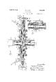
through a control head showing auxiliary pistons coupled in tandem with the'sealing rams;
Fig. 2 is a section Fig. 1.; and Y I Fig. 3 illustrates an alternate form of the invention.
.taken on the line 2- 2,
. a Fig. 1 is a longitudinal sectional elevation,
Referring to the drawings, the upper portion of a wellvcasing is illustrated at 1, on which the lower control head 2 is located, the upper control head 2a being. disposed above the lower head 2 and connected thereto by a nipple 111.
. Each of the control heads comprises a vertical extending hollow cylindrical body portion 3, the bore 4 of which is axially alined ,Withthe well casing 1, the said bore being threaded to receive corresponding threads on the casing l and nipple 1a.
Each control head, in the present-instance,
is provided with a pairof axially'alined and transversely, or radially extending portions 5, 5, which extend laterally and in diametrically opposed relation to each other from opposite sides of the vertical cylindrical M body portion 3 of the control head.
In each of the lateral'extensions 5 is formed a suitable ram chamber 6 which, at its forward end, communicates directly with the central bore 4 of the body portion 3 of the control head. In the present instance, each of the ram chambers 6 is of a cylindrical form, disposedwith its axis extending radially from the vertically disposed axis ofthe central bore 4: of the body portion 3 of the control head.
Suitably mounted within each of the cylindricalram chambers 6 is a longitudinal movable sealing. jaw or ram 7, the said sealing rams7, 7 being located at oppositesides of the center of the central bore 4, and movable in opposite directions toward and away from each other within their respective chambers 6. The outer ends of the chambers 6 are respectiv'ely closed by removable closure heads In the lower control head 2, each of the closure heads 8 constitutes a flanged integral head closing one end of an auxiliary cylinder 50. Each cylinder 50 has a bore 51 which extends inwardly from the opposite open flanged end 52 thereof to the said integral head8 at the closed flanged end of the cylin der.
The open end 52 of each of the auxiliary cylinders 50'is closed by a removable closure head 9, which is rovided with an elongated bearing 10 in w ich is slidably mounted a ram rod 11.
The ram rod 11 projects from the rear end of the sealing ram 7, through the closure head 8 and the associated auxiliary cylinder 50,
i the outer or tail end of the said ram rod being slidably mounted in the bearing 10 as above noted. I
The said tail end of each of the ramrods 11 is provided with a series of gear teeth 13, which are adapted to mesh with gear teeth 14 formed on a'gear segment 15. The gear .segment 15 'is pivotally mounted on a short shaft or stud 16 carried by lugs 17 formed on the bearinglO.
Each of the gear segments 15 is provided with a socket 19 adapted to receive a suitable handle 20, which constitutes levers by which the segments 15 may be turned about their pivots, to move the sealing rams 7, 7 toward and away from each other, as above noted.
To assist in the movement of the rams 7, 7, toward each other and into sealing position around the string of tubing m, which in in the drawing is shown as being lowered into the casing 1 through the central bore 4: of the control head 2, and forthe purpose of backing up the movement of the rams 7, and for maintaining the rams in their sealing positions with respect to the string of tubing, the outer end of each o'f'the bearings 10 is internally threaded as at 21. These threads 21 areadapted to receive corresponding external threads formed on jack screws 22, 22. V The said jack screws 22 are axially aligned with the ram rods 11, 11, as shown in the drawings, and each jack screw 22 is provided on its outer end with a suitable spider or wheel 23, having radially extending arms 24 provided with sockets 26 adaptedto receive a handle similar to the handle 20, whereby considerable leverage. may be obtained to force the sealing rams into sealing contactscrews 22 may be caused to follow the tail ends of the respective ram rods 11, when the sealing rams 7 are being moved by the levers 20, and when the gas pressure is not exceptionally high in the well casing 1.
When high gas pressure is encountered suitable lever handles may be applied to the sockets 26 of the spider 23 for supplying additional leverage for turning the jack screws 22, which, together with the operation of the handles 20 of the gear segments 15, will move the sealing aws 7 in opposition to the high pressure existing in the well casing.
In order to eliminate the laborious manual operation, and to make possible the operation of the rams 7 against the force exerted on-the front end of the rams by extremely high pressure in the well casing, the ram rods 11, 11 are provided with pistons which are located in the auxiliary cylinders 50, 50 respectively', and the fluid pressure is admitted from the well casing 1 to the rear ends of the ram chambers 6, 6 and to the rear ends of the aux.- iliary cylinders 50, 50 respectively.
3 In the form of the invention shown in Fig. 3, the fluid is conveyed by a suitable by-pass comprising a pipe 30 which is tapped into the body 3 of the control head 2 below the proj ections 5 thereon and communicates with the central bore 4 thereof. The flow of pressure from the bore 1 to the pipe 30 is controlled by a suitable valve 31.
The pipe 30 is provided with Y- fittings 32, 32 into one leg of each of whichis fitted a pipe 33. .The opposite end of each pipe 33 is tapped into an opening 34 formed in the head 8, which communicates withthe rear end of the ram chamber6, behind the ram 7 situated therein.
.In the third leg of each Y-fitting 32 is threaded apipe 35, on the outer end of which is mounted a Y-fitting 36. Into one leg of the site end of the pipe 37 is threaded into an aperture 38 formed in the head 9 of the auxiliary cylinder 50, affording communication to the rear end of the bore 51 of the auxiliary cylinder 50 at the rear side of the piston 60 located within the said auxiliary cylinder50.
In the third leg of the Y-fitting 36 is mounted a suitable relief valve 39 by which, when the valve 31 is closed, the pressure may be relieved from the rear ends of the chambers 6 and cylinders 50.
The forward end of the auxili'arycylinder '50 is provided with a pet cock 10 which func tions as a breather for the port-ion of the cylinder 50 between the forward end of the piston 60 and the rear end of the head 8.
Vvhile .the above described arrangement of the by-pass operates efliciently, when extremely high pressures are encountered, the pressure rushing upwardly between the opposed forward ends of the rams from the underside of the rams, as the rams start to move apart, has a tendency to loosen the packing in the front'ends of the rains 7, 7, and for this reason I employ means for equalizin the pressure above and below the rams in the ore 4 of the control head 2, as shown in Figs. 1 and 2, wherein a by-pass 130 is tapped at one end into the bore 4 of'the body 3 of the control head 2 at a point below the sealing rams 7,7 and is tapped at its opposite end into the bore 4 at a point above the sealing rams 7, 7. This by-pass is controlled by a valve 131 and is provided with a vent 139.v
Then the upper control head 2a'and the vent 139 are closed and the valve 131 opened the pressure from the casing '1 passes to the upper end, of the control head 2, thereby equalizing the pressure above and below the sealing rams 7, 7, thus, when the sealing rams start to open there is an equalized rush of pressure from both sides of the rams into the crevice formed between the opposed faces of the two moving rams, consequently no injury of the packing iseflec ted.
I prefer also to by-pass the fluid from-the upper end of the control head 2 through bypass openings133, 133, formed in the ,rams 7,7, tothe rear ends of the ram chambers 6, 6, thence through by-pass pipes 135, 135 from-the rear ends of the chambers 6, 6 to the rear ends of the auxiliary cylinders 50, 50.
Obviously, when the valve 131 is opened as above noted, the pressure above, below and between the rams 7, 7, the pressure at the rear.
ends of the rams in thechambers 6, 6, and the pressure at the rear ends of the pistons 60, 60 in the auxiliary chambers 50, will be equalized with the pressure in the well casing 1, and with the sum of the effective areas at the rear ends of the rams and pistons being substantially equal to the effective-areas of the front ends of the rams no difliculty is found in operating the rams to either an open or a closed position.
Mounted in the bore 51 of each of the aux- \iliary cylinders 50 is an interchangeable sleeve or lining 65,-the outer diameter of which is substantially equal to the diameter of the bore 51 of the cylinder 50, in order to have the lining 65 fit snugly within the said bore The bore 66 of the lining-65 may be of any desired diameter, depending upon the result desired, and the piston on the ram rod 11 is adapted to be made with a diameter corresponding to the bore 66 of the lining 65 which is to be used.
In the present instance the lining 65 is provided with suitable threads 67 adjacent one of the sealing rams 7 a lining 65 is placed said rams to be readily moved by operation 52 thereof, whereby As above noted the front or sealingend of each of the sealing rams 7 has a greater effective area, against which the gas pressure operates, than has the rear end 7 5. of the said I ram, the diflerence in the areas of the two 70 faces being substantially equal to the crosssectional area of the ram rod 11.
When it-is desired to equalize the force exerted by the gas at the opposite ends of each in the cylinder 50 which'will have an area substantially twice as'great as the cross-sectional area of the ram rod 11, which, when the ineffective cross-sectional area of the ram rod is deducted, for the reason that the ram rod passes completely through the cylinder 50, leaves a remaining effective area of the piston 60 which will be substantially equal to the cross-sectional area of-the ram rod 11, and this effective area of the'piston added to the effective area of the face 75 of the ram 7 produces a total effective surface area for the rear end of the sealing ram 7 which is substantially equal to the effective surface areas of the front end of the said ram 7. Thus, with the gas passing to the rear ends of the chambers 6 and cylinders 50, and acting against the effective rear surfaces 75 of the sealing rams 7 and the effective rear surfaces 76 of the pistons 60 there will be a counter-balancing of the pressure and the force exerted thereby at each end of each of. the sealing rams 7, which will permit the of the handles 20, the jack screws 22, in such instances, being used merely to back up the movement of the rams 7 and to lock the same in sealing contact with the string of tubing w.
Obviously if it is desired to have the force exerted on the rear end of each of the scaling i rams 7 slightly less than the force'exerted on the front end of the said sealing rams a liner 65 of smaller bore diameter and a correspondingly sized piston 60 will be used, whereby the sum of the efiective areas of the surfaces 75 and 76 of the sealing ram 7 and piston 60 respectively will be less than the effective area of the front sealing face of each ram.
On the other hand, if it is desired to have a greater force exerted at the rear of the sealing ram 7, whereby the rains will be moved into sealing contact with the string of tubing by the pressure in the well alone, the bore diameter 66 of the inserted lining 65 willbe increased, or the'lining 65 will be entirely eliminated, and a correspondingly sized piston 60 applied to the ram rod 11, whereby the sum of the effective areas 75 and 76 of the ram 7 and piston 60 respectively will be greater than the effective area of the front or sealing surface of the ram 7, consequently the force exerted against these surfaces 75 and 76 will be greater than the force exert-v .ed against the sealing surface of the ram 7,
adapted to be suiiiciently greater than the for said chamber from and, even though the pressures at each end of the said sealing ram 7 will be equal, or substantially so, this pressure acting against the combined effective areas of the surfaces 75 and 7 6 will exert a force thereon which will ce exerted against the front sealing surface of the ram 7 to cause the ram '7 to move forwardly into sealing contact with the string of tubing 03.
From the above description, it will be ob vious that by making the lining 65 interchangeable and the pistons also interchangeable to agree with the lining I may vary the area of the effective surface of the piston 60 to any desired degree for obtaining any of the desired results above noted.
Obviously any of the well known means for detachably securing a piston to a piston rod may be employed for removably securing the pistons 60 to the ram rods 11 or the pistons may be permanently attached to the ram rods, and when a differently sized lining is to be used the ram rod may be detached from the rain 7 and. the entire ram rod 11 with the permanent piston therein may be replaced by a similar ram rod having a piston corresponding in diameter to the bore of the new lining to be used, the ram rod 1.1 being threaded into or otherwise secured in the ram 7 i v I claim:
1. A control head, forv well casings, having a passageway communicating with the well casing and a chamber extending laterally from and communicating with said passageway, a sealing element in said chamber adapted to have its front end projectedinto said passageway, a rod projecting through therearend of said sealing element, an auxiliary cylinder, a piston in said auxiliary cylinder and operatively connected to said rod, and means affording intercommunication between the rear ends of the chamber and auxiliary cylinder and between said rear ends and the well casing ,for conducting fluid from the well casing to the rear ends of the said chamber and the auxiliary cylinder equalizing the pressures in said rear ends behind the sealing element and piston with the pressure in the well casing and at the exposed end of the sealing element proj ecting into said passageway.
2. A control head, for well casings, having a passageway communicating with the well casing and a chamber extending laterally from and communicating with said passageway, a sealing element in said chamber have its front end projected into said passageway, a rod projecting through said chamber from the rear end of said sealing element, an auxiliary cylinder, a piston in said auxiliary cylinder and operatively connected to said rod, means afiordin-g intercommunication between the rear endsof the chamber and auxiliary cylinder and between ed to way,
said rear ends and the well casing for conducting fluid from the well casing to the rear ends of the said chamber and the auxiliary cylinder equalizing the pressures in said rear ends behind the sealing element and piston with the pressure in the well casing and at the exposed end of the sealing'elem'entprojecting into said passageway, and means for controlling the fiow of fluid through the conducting means.
3. A control head, for well casings, having a passageway communicating with the well casing and a chamber extending laterally from and communicating with said passageway, a sealing element in said chamber adapt have its front end projected into'said passageway, a rod projecting through said chamber from the rear end of said sealing element, an auxiliary cylinder, a piston in said auxiliary cylinder and operatively connected to said rod, means afiording intercommunication between the rear ends of the chamber and auxiliary cylinder and between said rear ends and the well casing for conducting fluid from the well casing to the rear ends of the said chamber and the auxiliary cylinder equalizing the pressures in said rear ends behind the sealing element and piston with the pressure in the well casing and at the exposed end of the sealing element projecting into said passageway, means for controlling the flow of fluid through the conducting for exhausting the fluid means, and means chamber and the casing and a chamber extending laterally from and communicating with said passagea sealing element in said chamber adapt- .ed to have its front end projected into said passageway, chamber from element, an auxiliary cylinder, a piston in said auxiliary cylinder and operatively connected to said rod, means affording intercommunication between the rear ends of the chamber and auxiliary cylinder and between a rod projecting through said i the rear end of said sealing 1 said rear ends and the well casing for conducting fluid from the well casing to the rear ends of the said chamber and the auxiliary cylinder equalizing the pressures in said rear ends behind the sealing element and piston with the pressure in the well casing and at the exposed end of the sealing element pro-' j ecting into said passageway, means for controlling the flow of fluid through the conducting means, means for exhausting the fluid from the rear end of the chamber and the auxiliary cylinder, and means for venting the opposite end of the auxiliary cylinder.
5; A control head, for well casings, having a passageway communicating with the well casing and'a chamber extending laterally from and communicating with said passage- 20 passageway, a rod way, a sealing element in said chamber adapted to have its front end projected into said passageway, a rod projecting through said chamber from the rear end of said sealing element, an auxiliary cylinder, a piston in said auxiliary cylinder and operatively connected to said rod, and means for conducting fluid from the well casing to the rear ends of the said chamber and the auxiliary cylinder, the
1 sum of the effective areas of the rear end of the sealing element and the piston being substantially equal to the effective area of the front end surface of the sealing element.
6. A control head, for well casings, havlng a passageway communicating with the well casing and a chamberextending laterally from and communicating with said passageway, a sealing element in said chamber adapted to have its front end chamber-from the rear end of saidsealing element, an auxiliary cylinder, a piston in said auxiliarly cylinder and. operatively connected to said rod, means for conducting fluid from the well casing to the rear ends of the said chamber and the auxiliary cylinder, the
sum of the effective areas of the rear end of the sealing element and the piston being substantially equal to the effective area of-the -3 front end surface of the sealing element, and
t A element, an
' ed to have its front end cylinder substantially aligned means for varying the effective area of the piston.
7 A control head, for well casings, having a passageway communicating with the well casing and I from and communicating with said passagea chamber extending laterally way, a sealing element in said chamber adaptprojected into said passageway, a rod projecting through said chamber from the rear end of said sealing auxiliary cylinder, a piston in said auxiliary cylinder and operatively connected to said rod, means for conducting fluid v T from the Well casing to the rear ends of the said chamber and the auxiliary cylinder, the
sum of the effective areas of the rear end of the sealing element and the piston being sub stantially equal to the efi'ective area of the front end surface of the sealing element, and an interchangeable lining in the cylinder for Varying the effective area of the piston.
8. A control head, for well casings, comprising a body portion having a central bore substantially aligned with the bore of the Well casingand a chamber extending laterally from said central bore, a, sealing ram in said lateral chamber and adapted to have its forward end projected from the lateral chambcr across the said central bore, an auxiliary with said lateral chamber, a rod extending from the rear end of the sealing ram through the lateral chamber and the auxiliary cylinder, a piston "on the ram rod in said projected into said projecting through said auxiliary cylinder, and means affording lntercommunlcatlon be-
Priority Applications (1)
| Application Number | Priority Date | Filing Date | Title |
|---|---|---|---|
| US474819A US1854058A (en) | 1930-08-12 | 1930-08-12 | Control head |
Applications Claiming Priority (1)
| Application Number | Priority Date | Filing Date | Title |
|---|---|---|---|
| US474819A US1854058A (en) | 1930-08-12 | 1930-08-12 | Control head |
Publications (1)
| Publication Number | Publication Date |
|---|---|
| US1854058A true US1854058A (en) | 1932-04-12 |
Family
ID=23885065
Family Applications (1)
| Application Number | Title | Priority Date | Filing Date |
|---|---|---|---|
| US474819A Expired - Lifetime US1854058A (en) | 1930-08-12 | 1930-08-12 | Control head |
Country Status (1)
| Country | Link |
|---|---|
| US (1) | US1854058A (en) |
Cited By (14)
| Publication number | Priority date | Publication date | Assignee | Title |
|---|---|---|---|---|
| US2522444A (en) * | 1946-07-20 | 1950-09-12 | Donovan B Grable | Well fluid control |
| US2541968A (en) * | 1949-04-25 | 1951-02-13 | W K M Company | Gate valve |
| US2642942A (en) * | 1950-08-15 | 1953-06-23 | Charles B Reynolds | Drilling equipment and well pipe cleaner |
| US3791616A (en) * | 1971-09-08 | 1974-02-12 | Hydril Co | Non-rotating ram rod locking assembly for blowout preventer |
| US3871613A (en) * | 1971-09-08 | 1975-03-18 | Robert K Lerouax | Non-rotating ram rod locking assembly for blowout preventer |
| US4214605A (en) * | 1978-01-11 | 1980-07-29 | Otis Engineering Corporation | Actuator for wireline blowout preventer |
| US5735502A (en) * | 1996-12-18 | 1998-04-07 | Varco Shaffer, Inc. | BOP with partially equalized ram shafts |
| WO2003046424A2 (en) * | 2001-11-26 | 2003-06-05 | Anthony Ray Boyd | High torque and high capacity rotatable center core and floatable sealed body assemblies with universals ram applications and method |
| US6637516B1 (en) * | 2001-11-26 | 2003-10-28 | Anthony R. Boyd | High torque and high capacity rotatable center core and floatable sealed body assemblies with universal RAM applications and method |
| US20050242308A1 (en) * | 2004-05-01 | 2005-11-03 | Gaydos Stephen T | Blowout preventer and ram actuator |
| US20140069531A1 (en) * | 2012-09-07 | 2014-03-13 | Cameron International Corporation | Blowout Preventer Status Assembly |
| WO2015088730A1 (en) * | 2013-12-12 | 2015-06-18 | Hydril Usa Manufacturing Llc | Wellbore pressure assisted blowout preventer |
| US20190390782A1 (en) * | 2018-06-26 | 2019-12-26 | John R. Goetzinger | Slide Valve for Controlling Fluid Flow |
| US11603730B2 (en) * | 2018-07-31 | 2023-03-14 | National Oilwell Varco, L.P. | Blowout preventer testing apparatus and method |
-
1930
- 1930-08-12 US US474819A patent/US1854058A/en not_active Expired - Lifetime
Cited By (24)
| Publication number | Priority date | Publication date | Assignee | Title |
|---|---|---|---|---|
| US2522444A (en) * | 1946-07-20 | 1950-09-12 | Donovan B Grable | Well fluid control |
| US2541968A (en) * | 1949-04-25 | 1951-02-13 | W K M Company | Gate valve |
| US2642942A (en) * | 1950-08-15 | 1953-06-23 | Charles B Reynolds | Drilling equipment and well pipe cleaner |
| US3791616A (en) * | 1971-09-08 | 1974-02-12 | Hydril Co | Non-rotating ram rod locking assembly for blowout preventer |
| US3871613A (en) * | 1971-09-08 | 1975-03-18 | Robert K Lerouax | Non-rotating ram rod locking assembly for blowout preventer |
| US4214605A (en) * | 1978-01-11 | 1980-07-29 | Otis Engineering Corporation | Actuator for wireline blowout preventer |
| US5735502A (en) * | 1996-12-18 | 1998-04-07 | Varco Shaffer, Inc. | BOP with partially equalized ram shafts |
| FR2757208A1 (en) | 1996-12-18 | 1998-06-19 | Varco Shaffer Inc | WELL SHUTTER BLOCK WITH PARTIALLY EQUALIZED RAMS, ASSEMBLY FORMING RAMS EQUIPPED WITH THE SAME AND METHOD FOR CLOSING THE SAME |
| WO2003046424A3 (en) * | 2001-11-26 | 2004-08-05 | Anthony Ray Boyd | High torque and high capacity rotatable center core and floatable sealed body assemblies with universals ram applications and method |
| US6637516B1 (en) * | 2001-11-26 | 2003-10-28 | Anthony R. Boyd | High torque and high capacity rotatable center core and floatable sealed body assemblies with universal RAM applications and method |
| US6651746B2 (en) * | 2001-11-26 | 2003-11-25 | Anthony R. Boyd | High torque and high capacity rotatable center core and floatable sealed body assemblies with universals ram applications and method |
| US20040003920A1 (en) * | 2001-11-26 | 2004-01-08 | Boyd Anthony R. | High torque and high capacity rotatable center core with ram body assemblies |
| WO2003046424A2 (en) * | 2001-11-26 | 2003-06-05 | Anthony Ray Boyd | High torque and high capacity rotatable center core and floatable sealed body assemblies with universals ram applications and method |
| GB2398591B (en) * | 2001-11-26 | 2005-06-01 | Anthony Ray Boyd | High torque and high capacity rotatable center core and floatable sealed body assemblies with universals RAM applications and method |
| US7011160B2 (en) | 2001-11-26 | 2006-03-14 | Boyd Anthony R | High torque and high capacity rotatable center core with ram body assemblies |
| US6969042B2 (en) | 2004-05-01 | 2005-11-29 | Varco I/P, Inc. | Blowout preventer and ram actuator |
| US20050242308A1 (en) * | 2004-05-01 | 2005-11-03 | Gaydos Stephen T | Blowout preventer and ram actuator |
| US20140069531A1 (en) * | 2012-09-07 | 2014-03-13 | Cameron International Corporation | Blowout Preventer Status Assembly |
| US8978699B2 (en) * | 2012-09-07 | 2015-03-17 | Cameron International Corporation | Blowout preventer status assembly |
| US9957771B2 (en) | 2012-09-07 | 2018-05-01 | Cameron International Corporation | Blowout preventer status assembly |
| WO2015088730A1 (en) * | 2013-12-12 | 2015-06-18 | Hydril Usa Manufacturing Llc | Wellbore pressure assisted blowout preventer |
| US9410393B2 (en) | 2013-12-12 | 2016-08-09 | Hydril USA Distribution LLC | Pressure assisted blowout preventer |
| US20190390782A1 (en) * | 2018-06-26 | 2019-12-26 | John R. Goetzinger | Slide Valve for Controlling Fluid Flow |
| US11603730B2 (en) * | 2018-07-31 | 2023-03-14 | National Oilwell Varco, L.P. | Blowout preventer testing apparatus and method |
Similar Documents
| Publication | Publication Date | Title |
|---|---|---|
| US1854058A (en) | Control head | |
| US3207221A (en) | Automatic blow-out preventor means | |
| US2912214A (en) | Blowout preventer | |
| US2752119A (en) | Blowout preventer | |
| US2483239A (en) | Multiple pressure fluid motor mechanism for pushing and pulling | |
| US2592197A (en) | Side-plug hydraulic cellar gate | |
| US2296819A (en) | Rock drill | |
| US2810550A (en) | Earth boring machine | |
| US2313177A (en) | Blowout preventer and valve | |
| US1932685A (en) | Brake appplying means | |
| US1637505A (en) | Rotary hydraulic jar mechanism | |
| US2747673A (en) | Pulling tool | |
| US3052317A (en) | Means for use in the lubrication of fluid controlling valves and other articles | |
| US1509000A (en) | Power mechanism | |
| US2154955A (en) | Well casing control valve | |
| US2654563A (en) | Valve with removable seat | |
| US2578959A (en) | Hydraulic system for drilling rigs | |
| US2121268A (en) | Valve for well testing tools | |
| GB2166785A (en) | Blowout preventer | |
| US2194254A (en) | Pressure equalizer for blowout preventers | |
| US3132662A (en) | Valve apparatus for use as a blowout preventer or the like | |
| US2075706A (en) | Rock drill | |
| GB2037630A (en) | Hydraulic drilling machine | |
| US3169584A (en) | Rock drilling apparatus | |
| US2022197A (en) | Fluid motor |