US1853811A - Electromagnetic fuel pump - Google Patents
Electromagnetic fuel pump Download PDFInfo
- Publication number
- US1853811A US1853811A US546308A US54630831A US1853811A US 1853811 A US1853811 A US 1853811A US 546308 A US546308 A US 546308A US 54630831 A US54630831 A US 54630831A US 1853811 A US1853811 A US 1853811A
- Authority
- US
- United States
- Prior art keywords
- plunger
- fuel
- pressure
- pump
- spring
- Prior art date
- Legal status (The legal status is an assumption and is not a legal conclusion. Google has not performed a legal analysis and makes no representation as to the accuracy of the status listed.)
- Expired - Lifetime
Links
Images

Classifications
-
- F—MECHANICAL ENGINEERING; LIGHTING; HEATING; WEAPONS; BLASTING
- F02—COMBUSTION ENGINES; HOT-GAS OR COMBUSTION-PRODUCT ENGINE PLANTS
- F02M—SUPPLYING COMBUSTION ENGINES IN GENERAL WITH COMBUSTIBLE MIXTURES OR CONSTITUENTS THEREOF
- F02M1/00—Carburettors with means for facilitating engine's starting or its idling below operational temperatures
-
- F—MECHANICAL ENGINEERING; LIGHTING; HEATING; WEAPONS; BLASTING
- F02—COMBUSTION ENGINES; HOT-GAS OR COMBUSTION-PRODUCT ENGINE PLANTS
- F02M—SUPPLYING COMBUSTION ENGINES IN GENERAL WITH COMBUSTIBLE MIXTURES OR CONSTITUENTS THEREOF
- F02M37/00—Apparatus or systems for feeding liquid fuel from storage containers to carburettors or fuel-injection apparatus; Arrangements for purifying liquid fuel specially adapted for, or arranged on, internal-combustion engines
- F02M37/04—Feeding by means of driven pumps
- F02M37/08—Feeding by means of driven pumps electrically driven
-
- F—MECHANICAL ENGINEERING; LIGHTING; HEATING; WEAPONS; BLASTING
- F02—COMBUSTION ENGINES; HOT-GAS OR COMBUSTION-PRODUCT ENGINE PLANTS
- F02M—SUPPLYING COMBUSTION ENGINES IN GENERAL WITH COMBUSTIBLE MIXTURES OR CONSTITUENTS THEREOF
- F02M2700/00—Supplying, feeding or preparing air, fuel, fuel air mixtures or auxiliary fluids for a combustion engine; Use of exhaust gas; Compressors for piston engines
- F02M2700/07—Nozzles and injectors with controllable fuel supply
-
- F—MECHANICAL ENGINEERING; LIGHTING; HEATING; WEAPONS; BLASTING
- F02—COMBUSTION ENGINES; HOT-GAS OR COMBUSTION-PRODUCT ENGINE PLANTS
- F02M—SUPPLYING COMBUSTION ENGINES IN GENERAL WITH COMBUSTIBLE MIXTURES OR CONSTITUENTS THEREOF
- F02M2700/00—Supplying, feeding or preparing air, fuel, fuel air mixtures or auxiliary fluids for a combustion engine; Use of exhaust gas; Compressors for piston engines
- F02M2700/43—Arrangements for supplying air, fuel or auxiliary fluids to a combustion space of mixture compressing engines working with liquid fuel
- F02M2700/4302—Arrangements for supplying air, fuel or auxiliary fluids to a combustion space of mixture compressing engines working with liquid fuel whereby air and fuel are sucked into the mixture conduit
- F02M2700/438—Supply of liquid to a carburettor reservoir with limitation of the liquid level; Aerating devices; Mounting of fuel filters
- F02M2700/4388—Supply of liquid to a carburettor reservoir with limitation of the liquid level; Aerating devices; Mounting of fuel filters with fuel displacement by a pump
- F02M2700/439—Supply of liquid to a carburettor reservoir with limitation of the liquid level; Aerating devices; Mounting of fuel filters with fuel displacement by a pump the pump being a membrane pump
Definitions
- This invention is a division of my copending application entitled Combination fuel ump and carburetor, filed September 3rd, 1930, Serial Number 47 9,529, and relates particularly to the fuel pump.
- suction produced by the air in passing through the throat or Venturi tube of the carburetor is do )ended upon to withdraw the fuel from-the oat. chamber and connected atomizing nozzle and to atomize the fuel, and the pressure previously applied to the fuel is not utilized.
- the object of the resent invention is to provide a force feed pump which delivers fuel under pressure to a carburetor; to provide a carburetor in which the pressure on the fuel is utilized to raise and discharge the fuel through the atomizing no zle; and, further, to provide means whereby the pressure on the fuel automatically regulates the pump and maintains the pressure constant.
- Fig. 1 is a central, vertical, longitudinal section through the fuel pump and connected carburetor
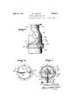
- Fig. 2 is a vertical cross section of the carburetor taken on line HH of Fig. 1,
- Fig. 3 is a side elevation-of the carburetor.
- Fi 4 is a plan view of the fuel pump showing t e top cover removed
- Fig. 5 isa cross section of the carburetor taken on line V-V of Fig. 2.
- A indicates in general a carburetor, and B a force feed fuel pump.
- the pump employed in the present instance is of the plunger type and is electrically operated. It consists of a housing which is divided into a plurality of sections such as indicated at 2, 3, 4, and 5. These sections are bolted together as shown and enclose the pump cylinder, the valves co-operating therewith, and the mechanism whereby the plunger of the pump is actuated.
- the lower housing section indicated at 2 is provided with a uel inlet chamber 6 and a discharge chamher 7 and it is also provided with a cylinder 8, an inlet valve 9, and a discharge valve 10, the valves 9 and 10 beingof the check valve type as they are spring seated and automatically actuated during the suction or discharge stroke of the p unger indicated at 11.
- This plunger is extended to pass through the housingsectious 3, 4 and 5 and it is guided by partition lates such as shown at 12 and 13.
- armature plate 18 mounted within the housing section 4t are a pair of electromagnetic coils 14 and 15 which surround core members 16 and 17, and co-operatin therewith is an armature plate 18 and a exible diaphragm 19; the diaphragm being secured between the housing sections 3 and 4 while the armature plate 18 is secured to the extended stem of the plunger 11. Also secured to the extended stem of the plunger is an adjustable collar 20.
- This is mounted within the housingsection 5 and engages a helical compression spring 21.
- the pump plunger 11 is operated by means of the armature plate 18 and the co-operating magnets 14 and 15. It is accordingly necessary to provide means for automatically making and breaking an electric circuit through the same.
- This is accomplished by providing a bracket 23 on which is pivotally mounted as at 24 a bell crank having two arms 25 and 26.
- a spring 27 connects arm. 26 with the bracket 23 and a second spring 28 connects the outer end of the arm 25 with a post 29 secured on the upper end of the plunger rod.
- the partition plate 12 secured to the upper end of the housing section 5 is con-' structed. of insulating material and carries a terminal member 30 which is coected through a wire 31 with a suitable source of current supply.
- the terminal member is also provided with a contact 32 and this is intermittently engaged by a contact 33 formed on the outer end of arm 25.
- a second terminal member 34 connects with the bracket 23 and this terminal is connected through a wire 35 with one of the magnetic coils. These are in turn connected with a wire 31a which forms the other side of the electric circuit.
- the housing 2 is extended as shown in Fig. 1 and forms the base for the carburetor. It also forms a combination fuel and air re- CeiVing chamber indicated at 40 as a partition member 41 is introduced between the fuel discharge passage 7 and the chamber 40.
- a pressure in the chamber 40 of the carburetor This pressure may be any pressure desired and it is determined by the area of the diaphragm 19 and the pressure of the spring 21. This pressure may be varied by adjusting the position of the collar 20.
- the bell crank lever is nothing more or less than a spring actuated snap type of switch, spring 27 being so con nected as to assume a position at one side or another of the pivot 24 as the lever oscillates,
- the carburetor generally indicated at A consists of a number of housing sections indicated at 2a, 42 and 43, these sections being secured together by means of bolts as shown.
- the upper housing section 43 contains a butterfly or throttle valve 44 secured on a cross shaft 45. It also contains an adjustable needle valve 46 and a housing 47 in which is journaled a multiple orifice valve 48.
- the housing 47 is provided with an extension 49 which passes through the housing 42 and downwardly into the housing 2a which forms an extension of the housing 2.
- the extension 49 has an inlet passage 50 formed therein which terminates in a tube 51 which extends downwardly into the fuel contained in the chamber 40.
- Valve 48 is provided with a number of radially disposed passages or discharge orifices of varying diameter as indicated at 53 and'with a large passage 54.
- the valve is secured on a cross shaft 55 which .eXtends through the side of the housing section 43 and which is rotated as will hereinafter be described.
- any one of the graduated orifices 53 may be moved into alignment with the discharge orifice or nozzle 52 while the larger opening 54 will register with the inlet 50.
- the quantity of fuel discharging through the nozzle or orifice 52 may thus also be varied by bringing one or another of the graduated orifices 53 into register with the nozzle and the quantity may further be regu lated by increasing or decreasing the pressure in chamber 40 through adjustment of the collar 20 on the plunger rod.
- Air is admitted to the carburetor through erating mechanism on an automobile and as such may be adjusted by the driver. Air entering the openings 61 of the choke and the openings 60 formed in the housing 42 enters a chamber 63 formed within the housing section 43.
- the air passages 60 are angularly positioned as shown in Fig. 2 and the air admitted to the chamber 63 will thus enter-tam 'gentially so as to cause a swirling motion.
- a disc 66 Interposed between the housing 47 and the top plate 65 of the housing section 42 is a disc 66, see Figs. 2 and 5.
- This disc has openings 67 formed therein which during rotation of disc 66 moves into and out of register with the openings 60, hence regulating the amount of air admitted to the mixing chamber.
- the disc 66 has a beveled gear segment 67 attached to its upper surface and this segment intermeshes with bevel gear pinion 68 secured on shaft 55.
- This shaft also has a gear segment 69 secured on its outer end which terminates in a lever 70.
- Shaft 45 carrying the throttle valve is also provided with a gear segment 71 and motion between shafts 55 and 45 is obtained by an intermeshing intermediate gear 72.
- the lever will be refei'redto as the throttle lever and'may be connected with .a foot or hand throttle mechanism in the usual manner.
- the pump When'the ignition switch or electric circuit through wires 31 and 31a is closed the pump immediately starts operating and as such builds up a predetermined or desired pressure in the chamber 40, this pressure being cushioned by air which is trapped above the fuel. The moment the engine is started and the throttle opened fuel under pressure is delivered to the atomizing nozzle and the air pressure in the chamber 40 will accordingly tend to drop. This is not the case, however, as the capacity of the pump is sufficient to maintain the pressure desired. The pump merely ceasing operation when a predetermined pressure is exceeded or merely slowing 'down to take care of the pressure required.
- any suitchamber 40 is insured due to the automatic operation of the pump and better atomization of the fuel is insured due to the fact that it is delivered to the atomizing nozzle under pressure and, it is further due to the swirling action on the incoming air in the mixing chamber.
- a uniform mixture is also insured due to the mechanical or metering control of air and fuel and as the carburetor is provided with an adjustable needlevalve and the pump with a pressure control the richness of the mixture may be increased or decreased asconditions may demand. 1
- a fluid pump comprising a cylinder, a loosely fitting plunger reciprocally mounted therein, inlet and discharge connections for the cylinder, electrically actuated means whereby reciprocal movement is imparted to the pump plunger, said means adapted to move the plunger in one direction, spring actuated means imparting movement to the plunger in the opposite direction, means whereby the movement of the plunger automatically makes or breaks the circuit through the electrically actuated means, and means actuated by pressure escaping around the plunger for holding it in an operative position.
- a fluid pump comprising a cylinder, a loosely fitting plunger reciprocally mounted therein, inlet and discharge connections for the cylinder, an electric magnet whereby reciprocal movement is imparted to theplunger in one direction, spring actuated means imparting movement to the plunger in an opposite direction, an electric switch controlling the circuit through the magnet, and means actuated by the reciprocal movement of the plunger and controlled by pressure escaping between the plunger and cylinder for opening and closing the switch.
- a fluid pump comprising a cylinder, a loosely fitting plunger reciprocally mounted therein, inlet and discharge connections for the cylinder, electrically actuated means whereby reciprocal -movement is imparted to the plunger, a flexible spring actuated diaphragm actuated by the pressure applied by the plunger to the fuel, and means actuated by movement of the diaphragm for automatically making or breaking the circuit through the electrically actuated means.
- a flui'd pump comprising a cylinder, a loosely fitting plunger reciprocally mounted therein, inlet and discharge connections for the cylinder, electrically actuated means with the plunger in one direction when the magnet is energized, a spring adapted to move the plunger and diaphragm in the opposite direction, and means whereby the fluid escaping between the plunger and cylinder walls stops movement of the plunger and diaphragm when a predetermined pressure is reached, said plunger and diaphragm when so actuated breaking the circuit through the magnet and said plunger and diaphragm moving in the opposite direction when the pressure is reduced and at the same time energizing themagnet.
- a fluid pump comprising'a cylinder, a loosely fitting plunger therein, electromagnetic means for reciprocating said plunger, means controlled by movement of said plunger for making and breaking a circuit to said electromagnetic means, a fluid-tight chamber surrounding said cylinder and having one end thereof sealed by a flexible diaphragm, and a connection between said diaphragm and said plunger, whereby fluid may escape between said cylinder and plunger and exert pressure on said diaphragm to move said plunger to a circuit breaking position.
- VYILLIAM R. HEWITT VYILLIAM R. HEWITT.
- a fluid pump comprising a cylinder, a loosely fitting plunger reciprocally mounted therein, inlet and discharge connections for the cylinder, an electric magnet whereby reciprocal movement is imparted to the pump plunger, a flexible diaphragmconnected with the plunger and adapted to move in unison
Description
April 12, 1932. w R. Ewn- 1,853,811
ELECTROMAGNETIC FUEL PUMP Original Filed Sept. 3, 1930 2 Sheets-Sheet l INVENTOR.
ifW *M A TTORNEYS.
April 12, 1932. w. R. HEWI TT 1,853,311
ELECTROMAGNETIC FUEL PUMP Original Filed Sept. 5, 1930 2 Sheets-Sheet 2 Patented Apr. '12, 1932 UNITED STATES WILLIAM B. HEWITT, OF NEW YORK, N. Y.
ELECTROMAGNETIC FUEL PUMP.
Original application illed September 3, 1980, Serial No. 479,529. Divided and this application filed June 28,
1931. Serial No. 546,308.
This invention is a division of my copending application entitled Combination fuel ump and carburetor, filed September 3rd, 1930, Serial Number 47 9,529, and relates particularly to the fuel pump.
The development of the internal combus ing the float chamber of the connected car-- buretor as this is usually vented, hence, the
suction produced by the air in passing through the throat or Venturi tube of the carburetor is do )ended upon to withdraw the fuel from-the oat. chamber and connected atomizing nozzle and to atomize the fuel, and the pressure previously applied to the fuel is not utilized.
The object of the resent invention is to provide a force feed pump which delivers fuel under pressure to a carburetor; to provide a carburetor in which the pressure on the fuel is utilized to raise and discharge the fuel through the atomizing no zle; and, further, to provide means whereby the pressure on the fuel automatically regulates the pump and maintains the pressure constant.
I The invention is shown by way of illustra tion in the accompanying drawings, in which- Fig. 1 is a central, vertical, longitudinal section through the fuel pump and connected carburetor,
Fig. 2 is a vertical cross section of the carburetor taken on line HH of Fig. 1,
Fig. 3 is a side elevation-of the carburetor.
Fi 4: is a plan view of the fuel pump showing t e top cover removed, and
Fig. 5 isa cross section of the carburetor taken on line V-V of Fig. 2.
Referring to the drawings in detail and particularly Fig. 1, A indicates in general a carburetor, and B a force feed fuel pump. The pump employed in the present instance is of the plunger type and is electrically operated. It consists of a housing which is divided into a plurality of sections such as indicated at 2, 3, 4, and 5. These sections are bolted together as shown and enclose the pump cylinder, the valves co-operating therewith, and the mechanism whereby the plunger of the pump is actuated. The lower housing section indicated at 2 is provided with a uel inlet chamber 6 and a discharge chamher 7 and it is also provided with a cylinder 8, an inlet valve 9, and a discharge valve 10, the valves 9 and 10 beingof the check valve type as they are spring seated and automatically actuated during the suction or discharge stroke of the p unger indicated at 11. This plunger is extended to pass through the housingsectious 3, 4 and 5 and it is guided by partition lates such as shown at 12 and 13. Mounte within the housing section 4t are a pair of electromagnetic coils 14 and 15 which surround core members 16 and 17, and co-operatin therewith is an armature plate 18 and a exible diaphragm 19; the diaphragm being secured between the housing sections 3 and 4 while the armature plate 18 is secured to the extended stem of the plunger 11. Also secured to the extended stem of the plunger is an adjustable collar 20.
. This is mounted within the housingsection 5 and engages a helical compression spring 21.
The pump plunger 11 is operated by means of the armature plate 18 and the co-operating magnets 14 and 15. It is accordingly necessary to provide means for automatically making and breaking an electric circuit through the same. This is accomplished by providing a bracket 23 on which is pivotally mounted as at 24 a bell crank having two arms 25 and 26. A spring 27 connects arm. 26 with the bracket 23 and a second spring 28 connects the outer end of the arm 25 with a post 29 secured on the upper end of the plunger rod. The partition plate 12 secured to the upper end of the housing section 5 is con-' structed. of insulating material and carries a terminal member 30 which is coected through a wire 31 with a suitable source of current supply. The terminal member is also provided with a contact 32 and this is intermittently engaged by a contact 33 formed on the outer end of arm 25. A second terminal member 34 connects with the bracket 23 and this terminal is connected through a wire 35 with one of the magnetic coils. These are in turn connected with a wire 31a which forms the other side of the electric circuit.
Vith the bell crank assuming the position shown in Fig. 1, a circuit is established through the magnetic coils 14 and 15 which can be traced as follows: Current entering on wire 31 passes through terminal 30, contacts 32 and 33, arm 25, bracket 23 and terminal 34. It then passes through wire 35, the connected magnetic coils 14 and 15 and returns to the source of supply through the wire 31a. circuit thus established energizes the cores 16 and 17 and the armature plate is accordingly attracted and as it is secured to the plunger pump 11 this will be raised as shown in Fig. 1, thereby producing a suction stroke causing valve 9 to open and admit fuel to the cylinder.
During upward movement of the plunger 11 post 29 on the upper end of the plunger rod is raised to a position Where spring 28 exerts an upward pull on the bell crank 25. Contacts 32 and 33 are separated the moment this occurs as arm 25 will instantly swing up- Wardly where its movement is checked by a stop member 38. The circuit is thus broken through the magnetic coils and spring 21, which was compresed during the upward movement of the plunger, willnow exert its presure to reverse the movement of the plunger and cause discharge of the liquid admitted to the cylinder. Valve 9 will accordingly close and valve 10 will open causing the fuel to enter the discharge passage 7.
The housing 2 is extended as shown in Fig. 1 and forms the base for the carburetor. It also forms a combination fuel and air re- CeiVing chamber indicated at 40 as a partition member 41 is introduced between the fuel discharge passage 7 and the chamber 40. In actual practice if the mechanism shown is installed on an automobile wires 31 and 3111 will be connected in the ignition circuit so that when the ignition switch is closed the pump will immediately start operation'and build up a pressure in the chamber 40 of the carburetor. This pressure may be any pressure desired and it is determined by the area of the diaphragm 19 and the pressure of the spring 21. This pressure may be varied by adjusting the position of the collar 20. Sufiice it to say, that when a predetermined pressure is obtained in the chamber 40 the pump will cease operation, this being due to the fact that a loose fit is maintained between the plunger 11 and the cylinder 8 so that fuel under pressure may leak by the plunger into the chamber 3a. The pressure on the fuel will naturally be the same as that in the chamber 40. This pressure is exerted on the diaphragm 19 and as the pressure increases it gradually forces the diaphragm upwardly and as the diaphragm is secured to the plunger 11 this will be raised upwardly and a position will finally be assumed where the spring actuated bell crank 25 will cease to function and remain in elevated position in engagement with the stop member 38. However, the moment the pressure drops below a predetermined pressure spring 21 forces the plunger downwardly and when a certain position is assumed the spring actuated bell crank will again function and intermittently make and break the circuit. The bell crank lever is nothing more or less than a spring actuated snap type of switch, spring 27 being so con nected as to assume a position at one side or another of the pivot 24 as the lever oscillates,
while the position of the spring 28 is controlled by the position of the plunger. In the position shown in Fig. 1, the pull of the spring 28 is upwardly and it pulls levers 25 and 26 to a position where spring 27 passes beyond the pivotal center 24, thus completing the upward movement, the downward movement being obtained when the plunger lever returns to lowered position where the pull of the spring 28 becomes downwardly and where it swings the levers 25 and 26 to a position where spring 27 passes to the opposite side of center 24, thus completing the downward movement of the levers in closing position.
The carburetor generally indicated at A consists of a number of housing sections indicated at 2a, 42 and 43, these sections being secured together by means of bolts as shown. The upper housing section 43 contains a butterfly or throttle valve 44 secured on a cross shaft 45. It also contains an adjustable needle valve 46 and a housing 47 in which is journaled a multiple orifice valve 48. The housing 47 is provided with an extension 49 which passes through the housing 42 and downwardly into the housing 2a which forms an extension of the housing 2. The extension 49 has an inlet passage 50 formed therein which terminates in a tube 51 which extends downwardly into the fuel contained in the chamber 40. The upper end of the housing is provided with an orifice 52 which aligns with the needle valve 46 and by raising or lowering the needle valve the amount of fuel discharged may be controlled. Valve 48 is provided with a number of radially disposed passages or discharge orifices of varying diameter as indicated at 53 and'with a large passage 54. The valve is secured on a cross shaft 55 which .eXtends through the side of the housing section 43 and which is rotated as will hereinafter be described.
By rotating shaft 55 and the valve 48 secured thereon any one of the graduated orifices 53 may be moved into alignment with the discharge orifice or nozzle 52 while the larger opening 54 will register with the inlet 50. The quantity of fuel discharging through the nozzle or orifice 52 may thus also be varied by bringing one or another of the graduated orifices 53 into register with the nozzle and the quantity may further be regu lated by increasing or decreasing the pressure in chamber 40 through adjustment of the collar 20 on the plunger rod.
Air is admitted to the carburetor through erating mechanism on an automobile and as such may be adjusted by the driver. Air entering the openings 61 of the choke and the openings 60 formed in the housing 42 enters a chamber 63 formed within the housing section 43. The air passages 60 are angularly positioned as shown in Fig. 2 and the air admitted to the chamber 63 will thus enter-tam 'gentially so as to cause a swirling motion.
This is important as chamber 63 forms the mixing chamber of the carburetor and as the air enters with a swirling motion a more unifgrm homogeneous mixture is insured. Interposed between the housing 47 and the top plate 65 of the housing section 42 is a disc 66, see Figs. 2 and 5. This disc has openings 67 formed therein which during rotation of disc 66 moves into and out of register with the openings 60, hence regulating the amount of air admitted to the mixing chamber. The disc 66 has a beveled gear segment 67 attached to its upper surface and this segment intermeshes with bevel gear pinion 68 secured on shaft 55. This shaft also has a gear segment 69 secured on its outer end which terminates in a lever 70. Shaft 45 carrying the throttle valve is also provided with a gear segment 71 and motion between shafts 55 and 45 is obtained by an intermeshing intermediate gear 72. The lever will be refei'redto as the throttle lever and'may be connected with .a foot or hand throttle mechanism in the usual manner. By im parting a swinging movement to the lever 70 shafts 45 and 55 will rotate in unison 'due to the intermediate gear 72 and the gear segments 69 and 71{ Rotation of shaft 45 causes opening or closing of the throttle valve 44 while rotation of shaft 55 causes rotation of register with the air inlets 60, hence a small quantity of air enters and mixes with a proportional amount of fuel; thorough mixing being insured by the swirling action of the air and the mixture finally discharges by the throttle valve and is delivered to the manifold of an engine in theusual manner. Further rotation of the- shafts 45 and 55 by means of the lever brings the next graduated opening 48 into register with the atomizing nozzle and causes further opening of the air inlet ports 60, hence a larger amount of fuel .and air is admitted and mixed to be delivered to the engine, and as the quantity of fuel and volume of air is at all times proportioned to varying engine speeds and loads a uniform and homogeneous mixture is insured. Atomization being insured first by swirling action of the air, and, secondly, by the atomizing action obtained by discharging the fuel through the nozzle 52 under pressure.
When'the ignition switch or electric circuit through wires 31 and 31a is closed the pump immediately starts operating and as such builds up a predetermined or desired pressure in the chamber 40, this pressure being cushioned by air which is trapped above the fuel. The moment the engine is started and the throttle opened fuel under pressure is delivered to the atomizing nozzle and the air pressure in the chamber 40 will accordingly tend to drop. This is not the case, however, as the capacity of the pump is sufficient to maintain the pressure desired. The pump merely ceasing operation when a predetermined pressure is exceeded or merely slowing 'down to take care of the pressure required.
The pump and carburetor shown in .the
present instance are connected with any suitchamber 40 is insured due to the automatic operation of the pump and better atomization of the fuel is insured due to the fact that it is delivered to the atomizing nozzle under pressure and, it is further due to the swirling action on the incoming air in the mixing chamber. A uniform mixture is also insured due to the mechanical or metering control of air and fuel and as the carburetor is provided with an adjustable needlevalve and the pump with a pressure control the richness of the mixture may be increased or decreased asconditions may demand. 1
While certain features of the present in vention are more or less specifically described, I wish it understood that various changes may be resorted to within the scope of the appended claims. Similarly, that the materials and finish of the several parts employed may be such as the manufacturer may decide, or varying conditions or uses may demand.
Having thus described my invention, what I claim'and desire to secure by Letters Patcut is l 1. A fluid pump comprising a cylinder, a loosely fitting plunger reciprocally mounted therein, inlet and discharge connections for the cylinder, electrically actuated means whereby reciprocal movement is imparted to the pump plunger, said means adapted to move the plunger in one direction, spring actuated means imparting movement to the plunger in the opposite direction, means whereby the movement of the plunger automatically makes or breaks the circuit through the electrically actuated means, and means actuated by pressure escaping around the plunger for holding it in an operative position.
2. A fluid pump comprising a cylinder, a loosely fitting plunger reciprocally mounted therein, inlet and discharge connections for the cylinder, an electric magnet whereby reciprocal movement is imparted to theplunger in one direction, spring actuated means imparting movement to the plunger in an opposite direction, an electric switch controlling the circuit through the magnet, and means actuated by the reciprocal movement of the plunger and controlled by pressure escaping between the plunger and cylinder for opening and closing the switch.
3. A fluid pump comprising a cylinder, a loosely fitting plunger reciprocally mounted therein, inlet and discharge connections for the cylinder, electrically actuated means whereby reciprocal -movement is imparted to the plunger, a flexible spring actuated diaphragm actuated by the pressure applied by the plunger to the fuel, and means actuated by movement of the diaphragm for automatically making or breaking the circuit through the electrically actuated means.
4.'A flui'd pump comprising a cylinder, a loosely fitting plunger reciprocally mounted therein, inlet and discharge connections for the cylinder, electrically actuated means with the plunger in one direction when the magnet is energized, a spring adapted to move the plunger and diaphragm in the opposite direction, and means whereby the fluid escaping between the plunger and cylinder walls stops movement of the plunger and diaphragm when a predetermined pressure is reached, said plunger and diaphragm when so actuated breaking the circuit through the magnet and said plunger and diaphragm moving in the opposite direction when the pressure is reduced and at the same time energizing themagnet.
6. A fluid pump, comprising'a cylinder, a loosely fitting plunger therein, electromagnetic means for reciprocating said plunger, means controlled by movement of said plunger for making and breaking a circuit to said electromagnetic means, a fluid-tight chamber surrounding said cylinder and having one end thereof sealed by a flexible diaphragm, and a connection between said diaphragm and said plunger, whereby fluid may escape between said cylinder and plunger and exert pressure on said diaphragm to move said plunger to a circuit breaking position.-
VYILLIAM R. HEWITT.
whereby reciprocal movement is imparted to the plunger, a flexible spring actuated diaphragm actuated by the'pressure applied by the plunger to the fuel, and a switch actuated by movement of the diaphragm for automatically making or breaking a circuit through the electrically actuated means.
5. A fluid pump comprising a cylinder, a loosely fitting plunger reciprocally mounted therein, inlet and discharge connections for the cylinder, an electric magnet whereby reciprocal movement is imparted to the pump plunger, a flexible diaphragmconnected with the plunger and adapted to move in unison
Priority Applications (1)
| Application Number | Priority Date | Filing Date | Title |
|---|---|---|---|
| US546308A US1853811A (en) | 1930-09-03 | 1931-06-23 | Electromagnetic fuel pump |
Applications Claiming Priority (2)
| Application Number | Priority Date | Filing Date | Title |
|---|---|---|---|
| US479529A US1902403A (en) | 1930-09-03 | 1930-09-03 | Combination fuel pump and carburetor |
| US546308A US1853811A (en) | 1930-09-03 | 1931-06-23 | Electromagnetic fuel pump |
Publications (1)
| Publication Number | Publication Date |
|---|---|
| US1853811A true US1853811A (en) | 1932-04-12 |
Family
ID=27046271
Family Applications (1)
| Application Number | Title | Priority Date | Filing Date |
|---|---|---|---|
| US546308A Expired - Lifetime US1853811A (en) | 1930-09-03 | 1931-06-23 | Electromagnetic fuel pump |
Country Status (1)
| Country | Link |
|---|---|
| US (1) | US1853811A (en) |
Cited By (10)
| Publication number | Priority date | Publication date | Assignee | Title |
|---|---|---|---|---|
| US2415687A (en) * | 1940-05-06 | 1947-02-11 | Alan F Gill | Fuel injection system for internal-combustion engines |
| US2576853A (en) * | 1948-06-18 | 1951-11-27 | Bendix Aviat Corp | Fuel supply system for internalcombustion engines |
| US2801621A (en) * | 1954-11-24 | 1957-08-06 | Mall Tool Company | Fuel-pump carburetor |
| US3242355A (en) * | 1966-03-22 | Electromagnetic device and parts therefor | ||
| US3242356A (en) * | 1966-03-22 | Davis, jr electromagnetic device | ||
| US4056333A (en) * | 1974-07-15 | 1977-11-01 | Valleylab | Intravenous feeding pump failure alarm system |
| US4828545A (en) * | 1984-02-08 | 1989-05-09 | Omni-Flow, Inc. | Pressure responsive multiple input infusion system |
| US5100380A (en) * | 1984-02-08 | 1992-03-31 | Abbott Laboratories | Remotely programmable infusion system |
| USRE36871E (en) * | 1984-02-08 | 2000-09-12 | Abbott Laboratories | Remotely programmable infusion system |
| EP1424491A1 (en) * | 2001-08-03 | 2004-06-02 | Mikuni Corporation | Fuel feeder |
-
1931
- 1931-06-23 US US546308A patent/US1853811A/en not_active Expired - Lifetime
Cited By (13)
| Publication number | Priority date | Publication date | Assignee | Title |
|---|---|---|---|---|
| US3242355A (en) * | 1966-03-22 | Electromagnetic device and parts therefor | ||
| US3242356A (en) * | 1966-03-22 | Davis, jr electromagnetic device | ||
| US2415687A (en) * | 1940-05-06 | 1947-02-11 | Alan F Gill | Fuel injection system for internal-combustion engines |
| US2576853A (en) * | 1948-06-18 | 1951-11-27 | Bendix Aviat Corp | Fuel supply system for internalcombustion engines |
| US2801621A (en) * | 1954-11-24 | 1957-08-06 | Mall Tool Company | Fuel-pump carburetor |
| US4056333A (en) * | 1974-07-15 | 1977-11-01 | Valleylab | Intravenous feeding pump failure alarm system |
| US4828545A (en) * | 1984-02-08 | 1989-05-09 | Omni-Flow, Inc. | Pressure responsive multiple input infusion system |
| US5100380A (en) * | 1984-02-08 | 1992-03-31 | Abbott Laboratories | Remotely programmable infusion system |
| US5304126A (en) * | 1984-02-08 | 1994-04-19 | Abbott Laboratories | Infusion system having plural fluid flow lines |
| US5464392A (en) * | 1984-02-08 | 1995-11-07 | Abbott Laboratories | Infusion system having plural fluid input ports and at least one patient output port |
| USRE36871E (en) * | 1984-02-08 | 2000-09-12 | Abbott Laboratories | Remotely programmable infusion system |
| EP1424491A1 (en) * | 2001-08-03 | 2004-06-02 | Mikuni Corporation | Fuel feeder |
| EP1424491A4 (en) * | 2001-08-03 | 2007-02-14 | Mikuni Kogyo Kk | Fuel feeder |
Similar Documents
| Publication | Publication Date | Title |
|---|---|---|
| US1853811A (en) | Electromagnetic fuel pump | |
| US2035636A (en) | Carburetor | |
| US2320012A (en) | Carburetor | |
| US2261490A (en) | Carburetor | |
| US1902403A (en) | Combination fuel pump and carburetor | |
| US2118038A (en) | Carburetor | |
| US2223987A (en) | Carburetor | |
| US1803666A (en) | Fuel feeding system | |
| US2895723A (en) | Carburetors for internal combustion engines | |
| US2240497A (en) | Carburetor | |
| US2130884A (en) | Carburetor | |
| US1872555A (en) | Carburetor | |
| US1861352A (en) | Carburetor | |
| US2518657A (en) | Fuel conditioning device | |
| US1612306A (en) | Carburetor structure | |
| US1828889A (en) | Carburetor | |
| US2009280A (en) | Carburetor | |
| US1682761A (en) | Carburetor | |
| US1961413A (en) | Carburetor | |
| US861758A (en) | Carbureter. | |
| US2087792A (en) | Carburetor | |
| US1789564A (en) | Carburetor | |
| US1985712A (en) | Carburetor | |
| US1042606A (en) | Carbureter. | |
| US1340123A (en) | Carbureter |