US1852973A - Ice box scale - Google Patents
Ice box scale Download PDFInfo
- Publication number
- US1852973A US1852973A US385489A US38548929A US1852973A US 1852973 A US1852973 A US 1852973A US 385489 A US385489 A US 385489A US 38548929 A US38548929 A US 38548929A US 1852973 A US1852973 A US 1852973A
- Authority
- US
- United States
- Prior art keywords
- ice box
- ice
- container
- box
- spring
- Prior art date
- Legal status (The legal status is an assumption and is not a legal conclusion. Google has not performed a legal analysis and makes no representation as to the accuracy of the status listed.)
- Expired - Lifetime
Links
Images

Classifications
-
- G—PHYSICS
- G01—MEASURING; TESTING
- G01G—WEIGHING
- G01G19/00—Weighing apparatus or methods adapted for special purposes not provided for in the preceding groups
-
- F—MECHANICAL ENGINEERING; LIGHTING; HEATING; WEAPONS; BLASTING
- F25—REFRIGERATION OR COOLING; COMBINED HEATING AND REFRIGERATION SYSTEMS; HEAT PUMP SYSTEMS; MANUFACTURE OR STORAGE OF ICE; LIQUEFACTION SOLIDIFICATION OF GASES
- F25D—REFRIGERATORS; COLD ROOMS; ICE-BOXES; COOLING OR FREEZING APPARATUS NOT OTHERWISE PROVIDED FOR
- F25D23/00—General constructional features
- F25D23/12—Arrangements of compartments additional to cooling compartments; Combinations of refrigerators with other equipment, e.g. stove
Definitions
- This invention relates to improvements in scales for ice boxes or refrigerators.
- a scale structure which may be incorporated with any conventional structure of ice box or refrigerator, which will accurately weigh ice placed in the ice box, and which is not subject to getting out of reair.
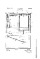
- Figure 1 is a front view of an ice box or refrigerator with which my invention has been incorpora-ted
- Figure 2 is a fragmentary vertical sec-- tional view taken substantially on the line 2-2 of Figure 1,
- Figure 3 is a horizontal sectional view' taken on the line 3"?) of Figure 1,
- Figure 4 is a partial central vertical section through the ice box or refrigerator
- Figure 5 is a top plan view of the ice box or refrigerator with its cover or top board removed.
- 10 indicates generally the top Wall of an ice box, 11 and 12 the side walls thereof,
- the walls may be constructed in the usual manner, as shown, and the top wall covered with a suitable top board 17.
- an ice box is usually provided with compartments, to which the doors 14, 15 and 16 permit free access.
- a box 18 preferably of metal, and with its Serial No. 385,489.
- a U-shaped clip 23 which pivotally supports a scale beam 24.
- One end of the beam is connected to the box 18 by a hook 25 and eye 26, while its other end is pivotally attached as at 27 to the upper end of a rod 28.
- the lower end of the rod is connected toV a suitable coil spring 29, said coil spring having its lower end ancho-red to a metal bracket 30.
- the rod 28 and spring 29 are by preference arranged in a vertical groove 31 formed in the associated side wall of the ice box.
- Thisv side wal-l' also carries a plate 32 7b provided with an apertured ear 32 at each end through which the rod 28 is slidable.
- the portion of the rod 28 between the ears 32" is provided with a pointer ory finger which moves in a longitudinal slot 34 provided in 80' a plate 35.
- the plate 35' has markings arranged adjacent the edges of slot 34 to ind'icate in pounds and7 ounces the amount of ice within the box 18.
- a glass panel 36 may be arranged forward of the plate 35 and witl' 85' in a suitable recess provided within the wall of the ice box.
- I claim 1 In combination with an ice box or refrigerator, a beam pivotally supported by the top wall of the ice box at a point intermediate its ends, an ice container connected to one end of the beam, guide tubes carried by said container, guide rods depending from the top wall of the ice box and freely slidable through said tubes whereby the container may have free upward and downward movement, an anchored coil spring, means connecting said spring to the other end of the beam, and means cooperative with said spring and the adjacent end of said beam whereby the expansion of the spring may be indicated as a function of the weight of material deposited in said container.
- a beam pivotally supported. by' the top wall of the ice box at a point intermediate its ends, an ice container connected to one end of the beam, guide members carried by said container and having openings through the saine, guide rods depending ⁇ from the top wall of the ice box and freely slidable through the openings in said members whereby the container may have free upward and downward movement, a drain p an carried by the lower ends of the guide rods, an anchored coil spring, means connecting one end of said spring to the other end of the beam, and means cooperative with said spring and the adjacent end of said beam whereby the expansion of the spring may be indicated as a function of the weight of material deposited in said container.
- a beam pivotally supported by the top wall of the ice box at a point intermediate its ends, an ice container connected to one end of the beam, guide tubes carried by said container, guide rods depending from the top wall of the ice box and freely slidable through said guide tubes whereby the container may have free upward and downward movement, a rod dependingly pivoted from the other end of said beam, an anchored coil spring attached to the lower end of the last named rod, and means connected to said last named rod whereby the expansion of the spring will be indicated as a function of the weight of material deposited in said container.
- a beam pivotally supported by the top wall of the ice box at a point intermediate its ends, an ice container connected to one end of the beam, guide tubes carried by said container, guide rods depending from the to wall of the ice box and freely slidable throng said guide tubes whereby the container may have free upward and downward movement, a rod dependingly pivoted from the other end of said beam, guide means for said last named rod, an anchored coil spring attached to the lower end of the last named rod, and means connected to said last named rod whereby the expansion of the spring will be indicated as a function of the weight of material deposited in said container.
- a beam pivotally supported by the top wall of the ice box ata point intermediate its ends, an ice container connected to one end of the beam, guide tubes carried by said container, guide rods depending from the top wall of th-e ice box and freely slidable through said guide tubes whereby the container may have free upward and downward movement, a rod dependingly pivoted from the other end of said beam, a guide for the last named rod, a coil spring anchored at one end beneath said guide, mean-s connecting the other end of said spring to the lower end of the last named rod, a graduated indicator member exposed through a wall of the refrigerator, and a pointer carried by said last named rod for cooperation with said member whereby the expansion of the spring will be indicated as al function of the weight of material deposited in said receptacle.
Description
l v t e e h S 2 w www Jog
EEA
Hmm n F Vl Rl.. E E n mi A ,Mm
F. E. JUSTUS ICE BOX SCALE April 5, 1932 2 sheets-sheet g Filed Aug. 13, 1929 www .Y
INVENTOR 56H7 fil-S ATTORNEY Patented pr. 5, 1932 PATENT FFICE FRED E. JUSTUS, OF EL] PASO, TEXAS ICE BOX SCALE ApplicationV filed August 13, 1929.
This invention relates to improvements in scales for ice boxes or refrigerators.
Among the general objects of the invention is to provide a scale structure which may be incorporated with any conventional structure of ice box or refrigerator, which will accurately weigh ice placed in the ice box, and which is not subject to getting out of reair.
A p It is also within the scope of the objects of the invention that the scale structure of this invention may be incorporated with any conventional structure of ice box without detracting from the appearance thereof, and
v that the number of pounds of ice within the ice box may be ascertained without opening any of its doors.
Other objects relating to the combination of elements forming my scale structure and structural advantages thereof will herein after appear in the detailed description to follow.
The invention is illustrated by way of example in the accompanying drawings, in
which:
Figure 1 is a front view of an ice box or refrigerator with which my invention has been incorpora-ted,
Figure 2 is a fragmentary vertical sec-- tional view taken substantially on the line 2-2 of Figure 1,
Figure 3 is a horizontal sectional view' taken on the line 3"?) of Figure 1,
Figure 4 is a partial central vertical section through the ice box or refrigerator, and
Figure 5 is a top plan view of the ice box or refrigerator with its cover or top board removed.
Referring to the drawings more particular- '40 ly, 10 indicates generally the top Wall of an ice box, 11 and 12 the side walls thereof,
13 the back wall, and 14, 15 and 16 doors therefor. The walls may be constructed in the usual manner, as shown, and the top wall covered with a suitable top board 17.
As is well understood, an ice box is usually provided with compartments, to which the doors 14, 15 and 16 permit free access. In the compartment provided for ice, I arrange a box 18, preferably of metal, and with its Serial No. 385,489.
front end open to permit ice to be easily placed therein. Upon each side wall of the box 18 there is secured a tubular guide 19 through which rods 20 depending from the top wall 10 of the ice box extend. lt is, of 55 course, to be understood that a greater number of guide rods 2G could be utilized if desired. The guide rods 2() support at their lower end a pan 21 which is provided with an outlet pipe 22. Also it is apparent the 6o pan 21 limits the downward movement of the box 18.
Centrally of the top wall 10 there is secured a U-shaped clip 23 which pivotally supports a scale beam 24. One end of the beam is connected to the box 18 by a hook 25 and eye 26, while its other end is pivotally attached as at 27 to the upper end of a rod 28. The lower end of the rod is connected toV a suitable coil spring 29, said coil spring having its lower end ancho-red to a metal bracket 30. The rod 28 and spring 29 are by preference arranged in a vertical groove 31 formed in the associated side wall of the ice box. Thisv side wal-l' also carries a plate 32 7b provided with an apertured ear 32 at each end through which the rod 28 is slidable. The portion of the rod 28 between the ears 32" is provided with a pointer ory finger which moves in a longitudinal slot 34 provided in 80' a plate 35. The plate 35' has markings arranged adjacent the edges of slot 34 to ind'icate in pounds and7 ounces the amount of ice within the box 18. A glass panel 36 may be arranged forward of the plate 35 and witl' 85' in a suitable recess provided within the wall of the ice box.
It is believed from the foregoing description of my invention when viewed with the accompanying drawings, that the structure and operation of my improved form of scales for ice boxes or refrigerators can be readily understood. It is, of course, understood that the graduated marks on the plate should be made inaccordance with the predeter- 95 mined strength of spring 29. `Alsoit might be noted that the rods 2O should loosely ft within the guide tubes; 19 in order that the box 18 may have freeupward and downward movement.
While I have shown and described the preferred form of my invention, I wish it understood that I am aware of the fact that the general combination and arrangement of the parts utilized might be changed by those skilled in the art without departing from the spirit of my invention as indicated by the appended claims.
I claim 1. In combination with an ice box or refrigerator, a beam pivotally supported by the top wall of the ice box at a point intermediate its ends, an ice container connected to one end of the beam, guide tubes carried by said container, guide rods depending from the top wall of the ice box and freely slidable through said tubes whereby the container may have free upward and downward movement, an anchored coil spring, means connecting said spring to the other end of the beam, and means cooperative with said spring and the adjacent end of said beam whereby the expansion of the spring may be indicated as a function of the weight of material deposited in said container.
2. In combination with an ice box or refrigerator, a beam pivotally supported. by' the top wall of the ice box at a point intermediate its ends, an ice container connected to one end of the beam, guide members carried by said container and having openings through the saine, guide rods depending` from the top wall of the ice box and freely slidable through the openings in said members whereby the container may have free upward and downward movement, a drain p an carried by the lower ends of the guide rods, an anchored coil spring, means connecting one end of said spring to the other end of the beam, and means cooperative with said spring and the adjacent end of said beam whereby the expansion of the spring may be indicated as a function of the weight of material deposited in said container.
3. In combination with an ice box or refrigerator, a beam pivotally supported by the top wall of the ice box at a point intermediate its ends, an ice container connected to one end of the beam, guide tubes carried by said container, guide rods depending from the top wall of the ice box and freely slidable through said guide tubes whereby the container may have free upward and downward movement, a rod dependingly pivoted from the other end of said beam, an anchored coil spring attached to the lower end of the last named rod, and means connected to said last named rod whereby the expansion of the spring will be indicated as a function of the weight of material deposited in said container.
4f. In combination with an ice box or refrigerator, a beam pivotally supported by the top wall of the ice box at a point intermediate its ends, an ice container connected to one end of the beam, guide tubes carried by said container, guide rods depending from the to wall of the ice box and freely slidable throng said guide tubes whereby the container may have free upward and downward movement, a rod dependingly pivoted from the other end of said beam, guide means for said last named rod, an anchored coil spring attached to the lower end of the last named rod, and means connected to said last named rod whereby the expansion of the spring will be indicated as a function of the weight of material deposited in said container.
5. In combination with an ice box or refrigerator, a beam pivotally supported by the top wall of the ice box ata point intermediate its ends, an ice container connected to one end of the beam, guide tubes carried by said container, guide rods depending from the top wall of th-e ice box and freely slidable through said guide tubes whereby the container may have free upward and downward movement, a rod dependingly pivoted from the other end of said beam, a guide for the last named rod, a coil spring anchored at one end beneath said guide, mean-s connecting the other end of said spring to the lower end of the last named rod, a graduated indicator member exposed through a wall of the refrigerator, and a pointer carried by said last named rod for cooperation with said member whereby the expansion of the spring will be indicated as al function of the weight of material deposited in said receptacle.
FRED E. J USTUS.
Priority Applications (1)
| Application Number | Priority Date | Filing Date | Title |
|---|---|---|---|
| US385489A US1852973A (en) | 1929-08-13 | 1929-08-13 | Ice box scale |
Applications Claiming Priority (1)
| Application Number | Priority Date | Filing Date | Title |
|---|---|---|---|
| US385489A US1852973A (en) | 1929-08-13 | 1929-08-13 | Ice box scale |
Publications (1)
| Publication Number | Publication Date |
|---|---|
| US1852973A true US1852973A (en) | 1932-04-05 |
Family
ID=23521585
Family Applications (1)
| Application Number | Title | Priority Date | Filing Date |
|---|---|---|---|
| US385489A Expired - Lifetime US1852973A (en) | 1929-08-13 | 1929-08-13 | Ice box scale |
Country Status (1)
| Country | Link |
|---|---|
| US (1) | US1852973A (en) |
Cited By (4)
| Publication number | Priority date | Publication date | Assignee | Title |
|---|---|---|---|---|
| EP1621835A2 (en) * | 2004-07-26 | 2006-02-01 | Liebherr-Hausgeräte Lienz GmbH | Refrigerator |
| US7138586B1 (en) * | 2006-08-03 | 2006-11-21 | Kim Brian S | Refrigerator with scale |
| US8944249B1 (en) | 2013-12-31 | 2015-02-03 | Gregory Mullaney | Refuse container with mechanical weight indicator and danger alerting |
| US9347821B1 (en) | 2012-08-31 | 2016-05-24 | Gregory Mullaney | Refuse container with weight indicator and danger alerting |
-
1929
- 1929-08-13 US US385489A patent/US1852973A/en not_active Expired - Lifetime
Cited By (5)
| Publication number | Priority date | Publication date | Assignee | Title |
|---|---|---|---|---|
| EP1621835A2 (en) * | 2004-07-26 | 2006-02-01 | Liebherr-Hausgeräte Lienz GmbH | Refrigerator |
| EP1621835A3 (en) * | 2004-07-26 | 2007-07-11 | Liebherr-Hausgeräte Lienz GmbH | Refrigerator |
| US7138586B1 (en) * | 2006-08-03 | 2006-11-21 | Kim Brian S | Refrigerator with scale |
| US9347821B1 (en) | 2012-08-31 | 2016-05-24 | Gregory Mullaney | Refuse container with weight indicator and danger alerting |
| US8944249B1 (en) | 2013-12-31 | 2015-02-03 | Gregory Mullaney | Refuse container with mechanical weight indicator and danger alerting |
Similar Documents
| Publication | Publication Date | Title |
|---|---|---|
| US2069499A (en) | Automatic clothes weighing hamper | |
| US1852973A (en) | Ice box scale | |
| US2193212A (en) | Laundry meter | |
| US1791111A (en) | Spring scale | |
| CN209777067U (en) | Multifunctional public recycling box for articles for daily use | |
| US1676565A (en) | Overflow alarm | |
| US1643469A (en) | Liquid-level gauge | |
| GB430004A (en) | Improvements in or relating to grading or weighing appliances | |
| US1872465A (en) | Scale beam | |
| US790529A (en) | Weighing mechanism. | |
| US2277957A (en) | Weighing scale | |
| US790528A (en) | Weighing mechanism for refrigerators. | |
| US2649293A (en) | Scale | |
| US1823415A (en) | Scale | |
| US2108421A (en) | Gravitational instrument | |
| US2037899A (en) | Egg tester | |
| US1236776A (en) | Combined refrigerator and ice-weighing apparatus. | |
| US1384767A (en) | Indicator and alarm for refrigerator drip-pans | |
| US1357683A (en) | Refrigerator-scale | |
| US1814591A (en) | Weighing scale | |
| US1966981A (en) | Meter | |
| US984264A (en) | Spring-scale. | |
| US1356287A (en) | Scale | |
| US1933277A (en) | Even balance scale | |
| US1487725A (en) | Refrigerator |