US1852512A - Well tubing plug - Google Patents
Well tubing plug Download PDFInfo
- Publication number
- US1852512A US1852512A US402488A US40248829A US1852512A US 1852512 A US1852512 A US 1852512A US 402488 A US402488 A US 402488A US 40248829 A US40248829 A US 40248829A US 1852512 A US1852512 A US 1852512A
- Authority
- US
- United States
- Prior art keywords
- plug
- tubing
- valve
- tbe
- body member
- Prior art date
- Legal status (The legal status is an assumption and is not a legal conclusion. Google has not performed a legal analysis and makes no representation as to the accuracy of the status listed.)
- Expired - Lifetime
Links
Images
Classifications
-
- E—FIXED CONSTRUCTIONS
- E21—EARTH DRILLING; MINING
- E21B—EARTH DRILLING, e.g. DEEP DRILLING; OBTAINING OIL, GAS, WATER, SOLUBLE OR MELTABLE MATERIALS OR A SLURRY OF MINERALS FROM WELLS
- E21B33/00—Sealing or packing boreholes or wells
- E21B33/10—Sealing or packing boreholes or wells in the borehole
- E21B33/12—Packers; Plugs
- E21B33/129—Packers; Plugs with mechanical slips for hooking into the casing
- E21B33/1295—Packers; Plugs with mechanical slips for hooking into the casing actuated by fluid pressure
Definitions
- the present invention contemplates a tool or device oi this character, and especially, a plug that may be position-ed in the bottom or lou/er end oi the tubing' or at anj,7 other point in thc tubing that may be desirable.
- il '.turther object is to provide a device oi this character that Will prevent the tluid or 'trom tlon'ing through the tubing during the removal ci the latter ⁇ from a flowing Well, "While, at the saine time, the fluid or gas Will be allowed to i'lotv between the tubing and casing and into storage tanks or pipe lines, as the case may be, Without loss ot tluid or il.
- still iurther object ot the invention is to construct a device oi' this type that is co1nparatively simple ot construction and which may be produced at a comparatively lovv cost.
- the invention consists in certain details oit' con struction and combinations and arrangements oi parts, all as will be hereinafter described and the novel tentures thereo'li particularly pointed out in the appended claims.
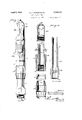
- ligure l is an elevational vievv of a tool constructed in accordance with the present invention
- Figure Q is a longitudinal sectional view of the several parts constituting the tool, but with said parts disassembled;
- lligure 3 is a transverse sectional View on the line 3-3 oi Figure 2;
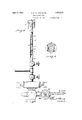
- litigare l is an elevational View illustrating the use ci the present plug.
- the plug may be said to consist oi a body portion -formed of upper and lorver sections between Which there are held means tor effecting a seal between the plug and the inner surface ot the tube in which the plug is inserted.
- Said body sections and the sealing means are oi tubular formation, and termed in the bore ot one oi the sections is a valve seat tor a valve capa blc of closing the passage through the plug proper.
- lthis valve is provided with a comparatively long stein, extending through suitable guides in the interior of the plug, andy is normally spring pressed against its side, so as to close thepassage through the tube.
- a housing with a spring which actuates said valve, and the upper end of the valve stein projects through said housing, whereby its protruding end portion may be engaged by suitable means 'for the purpose oi unseating the valve While the plug is being lowered in the Well.
- Means are also carried by the plug tor gripping against the interior Wall ot the tube lor holding the plug in the desired position in the tubing, these gripping means being oi a character. which ⁇
- the upper section oi the plug is indicated at l0, and the lower section at l1, and the 'two sections be ing termed with threaded portions tor connecting the same together.
- the tvvo sections are formed with a central bore 12, and held between the lower end of upper section l() and a shoulder i3 on lower section ll, there are means tor eilecting a seal or packing the space between the plug and the Wall of the tubing.
- Ilhese sealing means may take various forms, their specilic construction constituting no part oi the present invention, so that it will suilice to say that it will consist ot an elastic extensible member la capable oi being distended against the Wall ot' the tubing.
- the sealing means comprising the extensible elastic mem-- ber 1d, reinforced on its interior by a metal band 15 and what Will be termed the cap portion 16, is a Well known make oi swab that may be purchased on the open market.
- the intermediate portion oi section 10 is tapered upu BOU lili
- the central bore 12 of the plug is formed with a valve seat 2O for a valve 21, the valve being provided with means extending above the upper end of the plug and capable of being engaged by means of instruments from the surface of the ground for opening the valve.
- valve 21 is formed with a valve stem 22 that extends entirel through the plug, so that its upper end can e engaged by tools from the surface of the ground.
- the stem is guided longitudinally of the plug by ring-like guides 23, formed in the bore of each of the body sections 10, 11 and for yieldingly retaining the valve against its seat 20, a spring 24 is interposed between guide 23 in upper section 10;-
- FIG 4 there are shown more or less conventionally the connections at the surface of the ground for the purpose of illustrating the manner in which the present plug is used.
- the valve 29 in the flow line 30 leadin from casino' head 31 is opened, whereby uid or gas Eowing upwardly between the tubing 32 and well casing 33 mayy be carried olf to a suitable point, the gate valve 34 above the casing head being closed at this time.
- a tubing plug is then placed in a joint of tubing 35, which is screwed into tubing gate valve 36.
- a wire line stuhing box 39 connected to the top joint of tubing to prevent loss of liquid or gas through the upper end of the pipe. The weight of the polish rods pressing down on the protruding end of valve stem 22 forcesu the Valve 21 open at the bottom of the tool, permitting the oil or gas to low through the tubing while the tool is being lowered to the required depth.
- the polish rods are removed with the sand line, but the plug remains at the bottom of the tubing by reason of the fact that the grips 18 will prevent upward movement of the plug itself.
- spring 24 closes valve 2l immediately, and the space between the plug and tubing being sealed by member 14, the tubing can be pulled without the loss of any oil or gas, as all production on the part of the well will then be flowing between the tubing andthe casing, to and through iow line 30.
- a self anchoring plug for well casings comprising a cylindrical body portion having a beveled cut-away portion formed axially thereon, a central dovetail uide member projecting outwardly from sald beveled portion and extending axially thereon, a dog member having its inner surface axially slidable on said beveled portion and having a central dovetail slot interengaged with said guide member,and a stop member extending transversely across the outermost portion of said beveled portion and anchored to said body portion for limiting the movement of said dog and preventing its dissociation from said body portion.
- a full-automaticiuidpressureanchored fiow restricting plug for insertion through the outlet end of tubing through which fluid is flowing and is to be checked, comprising a tubular body member, a cup shaped pac er element carried by said body member and having a scaling lip of such diameter as to initially snugly engage the inner surface of the tubing, locking means carried by said body member permitting free movement of said body member in the direction opposite that of fluid fiow, but engageable with the inner surface of said tubing to lock said body member against movement in the direction of fluid flow, and a valve element normally urged to close the bore through said tubular bo y member; said valve having a portion so located and exposed with respect to the' other tenante lll Winde. l'lnid is tlovving and is to be clieclred,
- duid :tlovving Sind is to be clieclied9 comprising ubular body member9 a packer element carried by said body member and bathingJ vvben une" 'pounded7 a normal diameter suoli as to in lly snugly engage tbe inner surtzace ot tbe tubing, loclring ineens carried by said ttl body member permitting tree movement oi .
- seid body member in the direction opposite tbat ot tluid tlovv9 but engageable vvitb tbe inm ner snrif'ace ot seid tubing to lock said body member against movement in tbe direction ot :duid tion', a bead portion on said body men1- ber baving therethrough an arial centred apertnre
Description
pril 5, 1932. s. G. FoRNEY ET Al.
WELL TUBING PLUG Filed Oct. 25. 1929 2 Sheets-Sheet l u. /IIIIIIII April 5, 1932- s. G. FORNEY ET AL. 1,852,512
WELL TUBING PLUG Filed Oct. 25. 1929 2 Sheets-Sheet 2 gmc/Miou lotver Patented dpr@ b, T93@ ilClilll bi. AND MAG BORING, OF JE'URT 'WRTH, TEXAS, ASSIGNRS TU Gltlifli lPRUlDlUCTllDN llllltAbl'il", Ult" H'UHlN, TEXAS, .All CR'PRATEGN b' TEXAS application tiled October 'llliis invention relates to improvements in Well 'tubing plugs.
"lillhen tubing is to be pulled out oi a tlovving "Well, it is desirable that the bottom or end olf the string ot' tubing be closed so as to prevent the loss oi oil, gas, or Water, depending upon the type oi Well, which would otherwise tlovv through the tubing While the latter is being Withdrawn.
Primarily, the present invention contemplates a tool or device oi this character, and especially, a plug that may be position-ed in the bottom or lou/er end oi the tubing' or at anj,7 other point in thc tubing that may be desirable.
il '.turther object is to provide a device oi this character that Will prevent the tluid or 'trom tlon'ing through the tubing during the removal ci the latter `from a flowing Well, "While, at the saine time, the fluid or gas Will be allowed to i'lotv between the tubing and casing and into storage tanks or pipe lines, as the case may be, Without loss ot tluid or il. still iurther object ot the invention is to construct a device oi' this type that is co1nparatively simple ot construction and which may be produced at a comparatively lovv cost.
ll] ith these and other objects in view, the invention consists in certain details oit' con struction and combinations and arrangements oi parts, all as will be hereinafter described and the novel tentures thereo'li particularly pointed out in the appended claims.
ln the accompanying drawings:
ligure l is an elevational vievv of a tool constructed in accordance With the present invention Figure Q is a longitudinal sectional view of the several parts constituting the tool, but with said parts disassembled;
lligure 3 is a transverse sectional View on the line 3-3 oi Figure 2; and
litigare l is an elevational View illustrating the use ci the present plug.
Stated generally, the plug may be said to consist oi a body portion -formed of upper and lorver sections between Which there are held means tor effecting a seal between the plug and the inner surface ot the tube in which the plug is inserted. Said body sections and the sealing means are oi tubular formation, and termed in the bore ot one oi the sections is a valve seat tor a valve capa blc of closing the passage through the plug proper. lthis valve is provided with a comparatively long stein, extending through suitable guides in the interior of the plug, andy is normally spring pressed against its side, so as to close thepassage through the tube., @n the upper section of the plug body, there is a housing with a spring which actuates said valve, and the upper end of the valve stein projects through said housing, whereby its protruding end portion may be engaged by suitable means 'for the purpose oi unseating the valve While the plug is being lowered in the Well. Means are also carried by the plug tor gripping against the interior Wall ot the tube lor holding the plug in the desired position in the tubing, these gripping means being oi a character. which `|would permit the plug to be lowered in the tubing but Which, at all times, Will prevent an upward movement oi the plug.
Referring to the drawings, the upper section oi the plug is indicated at l0, and the lower section at l1, and the 'two sections be ing termed with threaded portions tor connecting the same together. The tvvo sections are formed with a central bore 12, and held between the lower end of upper section l() and a shoulder i3 on lower section ll, there are means tor eilecting a seal or packing the space between the plug and the Wall of the tubing. Ilhese sealing means may take various forms, their specilic construction constituting no part oi the present invention, so that it will suilice to say that it will consist ot an elastic extensible member la capable oi being distended against the Wall ot' the tubing. litmight be added that the sealing means comprising the extensible elastic mem-- ber 1d, reinforced on its interior by a metal band 15 and what Will be termed the cap portion 16, is a Well known make oi swab that may be purchased on the open market.
For the purpose of retaining the plug in the desired position in the tubing, the intermediate portion oi section 10 is tapered upu BOU lili
wardly on its exterior surface and formed at this pointwith slide ways or guides 17 for gripping members 1'8, whose inner surfaces conform to the cylindrical shape of section 10. The exterior surfaces of these gripping members are serrated in such fashion that the plug) will readily slip downwardly in a tubing, ut any effort to withdraw the plug from the tube upwardly will cause the teeth of the rippin members to bite into the surface o the tu ing. Upward movement of these gripping members relatively of section 10 when the plug is being lowered into the tubing, is limited by shoulders 19 on said body section. Excessive downward movement and dissociation of the gripping members is prevented by strips 17a which are anchored to the section 10 and extend transversely across the lower portions of the tapered surfaces and the guide 17.
While the plug is being lowered in the tubing in a well, it is necessary that oil or gas be permitted to iiow through the plug, but, after the plug has been positioned in the tubing, ready for the tubing to be pulled, it is necessary that not only the space between the plug and tubing be sealed, but the passage through the plug itself must also be closed. For this reason, the central bore 12 of the plug is formed with a valve seat 2O for a valve 21, the valve being provided with means extending above the upper end of the plug and capable of being engaged by means of instruments from the surface of the ground for opening the valve. Preferably, valve 21 is formed with a valve stem 22 that extends entirel through the plug, so that its upper end can e engaged by tools from the surface of the ground. The stem is guided longitudinally of the plug by ring-like guides 23, formed in the bore of each of the body sections 10, 11 and for yieldingly retaining the valve against its seat 20, a spring 24 is interposed between guide 23 in upper section 10;-
and a collar 25 o n said stem. In order to protect spring 24, it is venclosed within a housing 26 screwed on upper section 10. This housing is formed with openings 27 for the passage of iuid or gas, and wlth a centrally located passage 28 through which the upper end of the valve stern 22 projects. With this arrangement, pressure on a protruding end of stem 22 suiicient to overcome spring 24 will unseat valve 21 and, of course, when this pressure is relieved, spring 24 will return the valve to its seat.
In Figure 4, there are shown more or less conventionally the connections at the surface of the ground for the purpose of illustrating the manner in which the present plug is used. As 'shown in this figure, when4 it 1s desired to pull the tubing, the valve 29 in the flow line 30 leadin from casino' head 31 is opened, whereby uid or gas Eowing upwardly between the tubing 32 and well casing 33 mayy be carried olf to a suitable point, the gate valve 34 above the casing head being closed at this time. A tubing plug is then placed in a joint of tubing 35, which is screwed into tubing gate valve 36. rl`wo or three polish rods 37 made up together, or a sinker, is run on a sand line 38 to force the plug to a point near the bottom of the tubing, the gate valves 34; 36 being opened at this time to permit the plug to be lowered. Preferably, there is a wire line stuhing box 39 connected to the top joint of tubing to prevent loss of liquid or gas through the upper end of the pipe. The weight of the polish rods pressing down on the protruding end of valve stem 22 forcesu the Valve 21 open at the bottom of the tool, permitting the oil or gas to low through the tubing while the tool is being lowered to the required depth. After the plug has been lowered to the desired pooint, the polish rods are removed with the sand line, but the plug remains at the bottom of the tubing by reason of the fact that the grips 18 will prevent upward movement of the plug itself. Upon the rods being raised, spring 24 closes valve 2l immediately, and the space between the plug and tubing being sealed by member 14, the tubing can be pulled without the loss of any oil or gas, as all production on the part of the well will then be flowing between the tubing andthe casing, to and through iow line 30.
What is claimed is: Y 1. A self anchoring plug for well casings comprising a cylindrical body portion having a beveled cut-away portion formed axially thereon, a central dovetail uide member projecting outwardly from sald beveled portion and extending axially thereon, a dog member having its inner surface axially slidable on said beveled portion and having a central dovetail slot interengaged with said guide member,and a stop member extending transversely across the outermost portion of said beveled portion and anchored to said body portion for limiting the movement of said dog and preventing its dissociation from said body portion.
2. A full-automaticiuidpressureanchored fiow restricting plug for insertion through the outlet end of tubing through which fluid is flowing and is to be checked, comprising a tubular body member, a cup shaped pac er element carried by said body member and having a scaling lip of such diameter as to initially snugly engage the inner surface of the tubing, locking means carried by said body member permitting free movement of said body member in the direction opposite that of fluid fiow, but engageable with the inner surface of said tubing to lock said body member against movement in the direction of fluid flow, and a valve element normally urged to close the bore through said tubular bo y member; said valve having a portion so located and exposed with respect to the' other tenante lll Winde. l'lnid is tlovving and is to be clieclred,
en arming a tubular body member, e packer nt carried by said body member and lr Q :vlien nnezrpanded, a normal diende ter enen. ae to initially snugly engage tbe inrunL tace ont tbe tubing) locking means carrind oy said body member permitting tree i -1 ent ot said body member in the direcosite that oit fluid tlovv, but engagem i tbe inner surface of said 'tubing to aid body member against movement in tbe direction ot tluid dem and a valve element normally urged to close tbe bore tbrougb said tribdlar body member, said valve leaving a portion so located and eirposed vvitb respect to tbe other portions of the plug as to be car publie ot being lield open by means inserted "lie outlet end oi tbe tubing in order to permit dnid :tlovv through tbe body member tvliile tbe plug is being advanced to tbe deed location in tbe tubing.
dllbautomatic fluid pressure ancbored rioting plug tor insertion tbirougb tbe outlet end or tubing through vvlricb. duid :tlovving sind is to be clieclied9 comprising ubular body member9 a packer element carried by said body member and bathingJ vvben une" 'pounded7 a normal diameter suoli as to in lly snugly engage tbe inner surtzace ot tbe tubing, loclring ineens carried by said ttl body member permitting tree movement oi .seid body member in the direction opposite tbat ot tluid tlovv9 but engageable vvitb tbe inm ner snrif'ace ot seid tubing to lock said body member against movement in tbe direction ot :duid tion', a bead portion on said body men1- ber baving therethrough an arial centred apertnre disposed at tbe extreme top of the plug as unit, and a valve element normally "urged to close tbe bore through said tubular it@ body member, eaid valve having an operating member normally projecting through tbe eenn tral aperture ol the bead portion of tbe body member? but operative, when depressed Hush vvitli tbe top ci.E said head portion, to open said vnlve and permit fluid dow through tbe body member While tbe plug is being advanced to tbe desired location in tbe tubing.
SC'lT Gr. FRNEY.. Md@ U.. BOlNGr.
titl
i mi
Priority Applications (1)
| Application Number | Priority Date | Filing Date | Title |
|---|---|---|---|
| US402488A US1852512A (en) | 1929-10-25 | 1929-10-25 | Well tubing plug |
Applications Claiming Priority (1)
| Application Number | Priority Date | Filing Date | Title |
|---|---|---|---|
| US402488A US1852512A (en) | 1929-10-25 | 1929-10-25 | Well tubing plug |
Publications (1)
| Publication Number | Publication Date |
|---|---|
| US1852512A true US1852512A (en) | 1932-04-05 |
Family
ID=23592110
Family Applications (1)
| Application Number | Title | Priority Date | Filing Date |
|---|---|---|---|
| US402488A Expired - Lifetime US1852512A (en) | 1929-10-25 | 1929-10-25 | Well tubing plug |
Country Status (1)
| Country | Link |
|---|---|
| US (1) | US1852512A (en) |
Cited By (4)
| Publication number | Priority date | Publication date | Assignee | Title |
|---|---|---|---|---|
| US2522444A (en) * | 1946-07-20 | 1950-09-12 | Donovan B Grable | Well fluid control |
| US2536431A (en) * | 1945-09-20 | 1951-01-02 | William H Endsley | Well tubing plug |
| US2598512A (en) * | 1947-02-28 | 1952-05-27 | Hugh F Cypher | Method for running a liner in flowing gas wells |
| US2641322A (en) * | 1949-06-04 | 1953-06-09 | Arlis C Hartsell | Well fluid stabilizer |
-
1929
- 1929-10-25 US US402488A patent/US1852512A/en not_active Expired - Lifetime
Cited By (4)
| Publication number | Priority date | Publication date | Assignee | Title |
|---|---|---|---|---|
| US2536431A (en) * | 1945-09-20 | 1951-01-02 | William H Endsley | Well tubing plug |
| US2522444A (en) * | 1946-07-20 | 1950-09-12 | Donovan B Grable | Well fluid control |
| US2598512A (en) * | 1947-02-28 | 1952-05-27 | Hugh F Cypher | Method for running a liner in flowing gas wells |
| US2641322A (en) * | 1949-06-04 | 1953-06-09 | Arlis C Hartsell | Well fluid stabilizer |
Similar Documents
| Publication | Publication Date | Title |
|---|---|---|
| USRE17217E (en) | Casinoshoe | |
| US2092261A (en) | Tubing head for wells | |
| US2347726A (en) | Wire line pressure retaining core barrel | |
| US1852512A (en) | Well tubing plug | |
| US2389512A (en) | Tester for wells | |
| US2724443A (en) | Apparatus for automatically filling well casing | |
| US1659478A (en) | Combined guide plug and float valve for well casings | |
| US2412915A (en) | Pressure core barrel | |
| US3152639A (en) | Methods and apparatus for testing wells | |
| US2274093A (en) | Apparatus for completing submarine wells | |
| US2920764A (en) | Means for reducing liquid level in well tubing | |
| US2092822A (en) | Removable back pressure valve | |
| US2134200A (en) | Plug valve casing head | |
| US3378079A (en) | Sleeve valve apparatus | |
| US2171000A (en) | Formation tester | |
| US2218988A (en) | Adjustable flow bean | |
| US3626969A (en) | Method and apparatus for installing and removing gas lift valves in a well | |
| US2191702A (en) | Bypass fitting | |
| US3166124A (en) | Wellhead closure plug | |
| US2147896A (en) | Core taking apparatus | |
| US2177172A (en) | Apparatus for cementing wells | |
| US2591087A (en) | Hydropneumatic graduator | |
| US2751023A (en) | Devices for automatically filling well casing | |
| US2253396A (en) | Intermittent flow device | |
| US1839861A (en) | Cementing plug |