US1663254A - Process of making tie-rod ends - Google Patents
Process of making tie-rod ends Download PDFInfo
- Publication number
- US1663254A US1663254A US90841A US9084126A US1663254A US 1663254 A US1663254 A US 1663254A US 90841 A US90841 A US 90841A US 9084126 A US9084126 A US 9084126A US 1663254 A US1663254 A US 1663254A
- Authority
- US
- United States
- Prior art keywords
- tube
- ball
- rod ends
- seamless
- making
- Prior art date
- Legal status (The legal status is an assumption and is not a legal conclusion. Google has not performed a legal analysis and makes no representation as to the accuracy of the status listed.)
- Expired - Lifetime
Links
Images
Classifications
-
- B—PERFORMING OPERATIONS; TRANSPORTING
- B21—MECHANICAL METAL-WORKING WITHOUT ESSENTIALLY REMOVING MATERIAL; PUNCHING METAL
- B21D—WORKING OR PROCESSING OF SHEET METAL OR METAL TUBES, RODS OR PROFILES WITHOUT ESSENTIALLY REMOVING MATERIAL; PUNCHING METAL
- B21D41/00—Application of procedures in order to alter the diameter of tube ends
Definitions
- Leazsi GEORGE H. HUFFERD OF DETROIT, MICHIGAN; ASSIGNOR TO THOMPSON PRODUCTS INC., OF CLEVELAND, OHIO, A CORPORATION OF OHIO.
- the invention relates to a process for producing a connecting rod formed out of a light, seamless, metal tube, With an integral ball-joint housing, such as is disclosed and claimed in an application filed by mejointly with Frederick (l. Crawford on February 26, 1926, Serial No. 90,899. While I contemplate the employment of the process especially for the formation of the ends of tie rods and drag links of automobiles, the purpose to which the rod is to bc put isy not material.
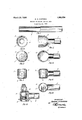
- Figure l is a view of a seamless metal ⁇ tube, partly in section from which the connecting rod is made according to my process;
- Fig. 2 illustrates the tube after the end has been expanded and upset to proper diameter
- Fig.i.3 is an end view thereof
- Fig. 4 illustrates theresult of the next step in the process, which consists in forming or spinning the expanded end shown in Fig. 2 into substantially spherical form;
- Fig. 5 is an end View of Fig. 4;
- Fig. 6 illustrates the result of the succeeding operation, which consists in shaping the substantially spherical end illustrated in Fig. 4 into the form o f a cylinder Whose axis is at right angles to the axis of the tube;
- Fig. 7 is an end view of Fig. 6.
- Fig. 8 is a bottom plan view of Fig. 6.
- Fig. l9 is a View of the connecting rod end as completed according to my process and assembled with a ball joint.
- tube 1 the end of which is enlarged or eX- panded, as illustrated at 2, the extent of the enlargement depending upon the size of the ball-joint housing or similar part which it is desired to-form upon the end of the tube.
- the same metal which forms the wall of the tube must also constitute the wall of the enlargement, from which it follows that, if the end of the tube is subjected to the process process is begun with a light, seamless metal of expansion alone, the resulting wall will be much thinner than the untreated wall of the tubo.
- the expanding operation is preferably so effected as to leave a segmental spherical surface 3 next to the body of the tube l, as indicated m Fig. 2.
- the end ouf the expanded portion is formed by spinning or otherwise, into a substantial sphere 4, as illustrated in Fig. 4.V
- This spherical end 4 is then die-formed, preferably by a lhot-forging method, into a cylinder V5 Whose axis is at right angles to the axis of the tube. the cylinder is completely removed, as in- Thereafter one end- 6 ot dicated at 7 (Fig. 9) and a concentric part of the opposite end is removed, so as to leave a ball-seat retaining and bearing surface 8, thus forming a ball-joint housing.
- housing so made is adapted to receive and retain a ball joint described in a co-pending application and Which is not my sole invention.
- This ball joint is fully illustrated in Fig. 9 and requires -no further description,
- bearing surface 8 is formed of two surfaces at substantially right anglcsto each other, the shape thereof is dependent merely upon the shape of the dies employed in forging the spl-ie'rical end 4 into thc cylinder. By selecting dies of other shapes this bearing surface might be the segment of a sphere or cone.
- the end ofl thetube to be formed for receiving a ball joint may be expanded Without upsetting, or expanded and'also upset, depending upon the'characteristics of the resulting article desired; but'as it is ordinarily desirable to have the greatest strength of such a part with the least Weight, it will be found best'to upset the expanded orenlargedportion of the tube so that the hous ingI will' have a strength equal to that of the body of the tube.
- VV'hat I calim is v 1.
- the process of making .a one-piece, seamless, tubular connecting rod, consisting in expanding the open end' of a seamless In the following claims which specify ⁇ the step of expanding' metal tube, forming it rinto substantially spherical lform, shaping the substantially spherical end intoy cylindrical form, and finally removing the end walls of the cylinder. f
Description
March 20,1928. 1,663,254
I G. HQ HUFFERD PROCESS' 0F MAKING TIE ROD ENDS Filed Feb. 26V. 1926 K' Patented Mar. 2o, 1928.
Leazsi GEORGE H. HUFFERD, OF DETROIT, MICHIGAN; ASSIGNOR TO THOMPSON PRODUCTS INC., OF CLEVELAND, OHIO, A CORPORATION OF OHIO.
PROCESS OF MAKING TIE-ROI) ENDS.
Application led February 26, 1926. Serial No. 90,841.
The invention relates to a process for producing a connecting rod formed out of a light, seamless, metal tube, With an integral ball-joint housing, such as is disclosed and claimed in an application filed by mejointly with Frederick (l. Crawford on February 26, 1926, Serial No. 90,899. While I contemplate the employment of the process especially for the formation of the ends of tie rods and drag links of automobiles, the purpose to which the rod is to bc put isy not material.
It is the object of this invention to produce such an article by novel and effective procedure and of which the cost of production Will be comparatively small.
In the annexed drawings illustrating the steps of the' process:
Figure l is a view of a seamless metal `tube, partly in section from which the connecting rod is made according to my process;
Fig. 2 illustrates the tube after the end has been expanded and upset to proper diameter;
Fig.i.3 is an end view thereof;
Fig. 4 illustrates theresult of the next step in the process, which consists in forming or spinning the expanded end shown in Fig. 2 into substantially spherical form;
Fig. 5is an end View of Fig. 4;
l Fig. 6 illustrates the result of the succeeding operation, which consists in shaping the substantially spherical end illustrated in Fig. 4 into the form o f a cylinder Whose axis is at right angles to the axis of the tube;
Fig. 7 is an end view of Fig. 6.
Fig. 8 is a bottom plan view of Fig. 6.
Fig. l9 is a View of the connecting rod end as completed according to my process and assembled with a ball joint.
Referring to the'drawings in detail in whichthc same reference character is used throughout to indicate the same part, the
The expanding operation is preferably so effected as to leave a segmental spherical surface 3 next to the body of the tube l, as indicated m Fig. 2. After the step of expansion the end ouf the expanded portion is formed by spinning or otherwise, into a substantial sphere 4, as illustrated in Fig. 4.V This spherical end 4 is then die-formed, preferably by a lhot-forging method, into a cylinder V5 Whose axis is at right angles to the axis of the tube. the cylinder is completely removed, as in- Thereafter one end- 6 ot dicated at 7 (Fig. 9) and a concentric part of the opposite end is removed, so as to leave a ball-seat retaining and bearing surface 8, thus forming a ball-joint housing. The
housing so made is adapted to receive and retain a ball joint described in a co-pending application and Which is not my sole invention. This ball joint is fully illustrated in Fig. 9 and requires -no further description,
except the explanation that it comprises a ball seat having a bore eccentric to its axis, adapted to rotate in the housing for purposes of adjustment/of the ball stud withy relation to the rod and to be xed in any adjusted position.
While I have illustrated the bearing surface 8 as being formed of two surfaces at substantially right anglcsto each other, the shape thereof is dependent merely upon the shape of the dies employed in forging the spl-ie'rical end 4 into thc cylinder. By selecting dies of other shapes this bearing surface might be the segment of a sphere or cone.
Inthe description above it is indicated that the end ofl thetube to be formed for receiving a ball joint may be expanded Without upsetting, or expanded and'also upset, depending upon the'characteristics of the resulting article desired; but'as it is ordinarily desirable to have the greatest strength of such a part with the least Weight, it will be found best'to upset the expanded orenlargedportion of the tube so that the hous ingI will' have a strength equal to that of the body of the tube.
the end of a metal tubey the expression is to be understood yas also covering the step of upsetting the metal Whenever such is deemed to be desirable. n
1t is apparent that Aby the method describedy the article disclosed may be effectively constructed and at a low cost. The method is capable of variation Iin detail and ibis therefore to be understood that it is not limited to the details described but includes -all processes comprehended Within the terms of the appended claims.
VV'hat I calim is v 1. The process of making .a one-piece, seamless, tubular connecting rod, consisting in expanding the open end' of a seamless In the following claims which specify `the step of expanding' metal tube, forming it rinto substantially spherical lform, shaping the substantially spherical end intoy cylindrical form, and finally removing the end walls of the cylinder. f
2. The process of making a one-piece, seamless, tubular` connecting rod, consisting in expanding the open end of 'a seamless metal tube, forn'iing it l into substantially spherical forni, shaping the substantially spherical end into cylindrical form, and finally completely removing one end wall of the cylinder and an inner concentric part of the other end wall soas to leave a. ball-*seat retaining shoulder.
' Signed by me this 22nd'd'ay of January, 1926.
eno.v H. HUFFERD.v
Priority Applications (1)
| Application Number | Priority Date | Filing Date | Title |
|---|---|---|---|
| US90841A US1663254A (en) | 1926-02-26 | 1926-02-26 | Process of making tie-rod ends |
Applications Claiming Priority (1)
| Application Number | Priority Date | Filing Date | Title |
|---|---|---|---|
| US90841A US1663254A (en) | 1926-02-26 | 1926-02-26 | Process of making tie-rod ends |
Publications (1)
| Publication Number | Publication Date |
|---|---|
| US1663254A true US1663254A (en) | 1928-03-20 |
Family
ID=22224576
Family Applications (1)
| Application Number | Title | Priority Date | Filing Date |
|---|---|---|---|
| US90841A Expired - Lifetime US1663254A (en) | 1926-02-26 | 1926-02-26 | Process of making tie-rod ends |
Country Status (1)
| Country | Link |
|---|---|
| US (1) | US1663254A (en) |
Cited By (4)
| Publication number | Priority date | Publication date | Assignee | Title |
|---|---|---|---|---|
| US2500592A (en) * | 1947-08-07 | 1950-03-14 | Kenneth E Whiteley | Self-lubricating, self-aligning bearing |
| US3431632A (en) * | 1963-06-17 | 1969-03-11 | Reiner Ind Inc | Method and apparatus for connecting the ends of flexible or resilient strings to tubular elements having closed ends |
| US3731517A (en) * | 1968-12-30 | 1973-05-08 | Patent And Devel Of North Caro | Method of fabricating a fluid dispersion nozzle |
| US6068380A (en) * | 1998-07-28 | 2000-05-30 | Gentex Corporation | Mirror mount having an integral spherical bearing |
-
1926
- 1926-02-26 US US90841A patent/US1663254A/en not_active Expired - Lifetime
Cited By (4)
| Publication number | Priority date | Publication date | Assignee | Title |
|---|---|---|---|---|
| US2500592A (en) * | 1947-08-07 | 1950-03-14 | Kenneth E Whiteley | Self-lubricating, self-aligning bearing |
| US3431632A (en) * | 1963-06-17 | 1969-03-11 | Reiner Ind Inc | Method and apparatus for connecting the ends of flexible or resilient strings to tubular elements having closed ends |
| US3731517A (en) * | 1968-12-30 | 1973-05-08 | Patent And Devel Of North Caro | Method of fabricating a fluid dispersion nozzle |
| US6068380A (en) * | 1998-07-28 | 2000-05-30 | Gentex Corporation | Mirror mount having an integral spherical bearing |
Similar Documents
| Publication | Publication Date | Title |
|---|---|---|
| US2733085A (en) | Latzen | |
| US1663254A (en) | Process of making tie-rod ends | |
| US1873453A (en) | Method of making a front axle | |
| US4368572A (en) | Method of manufacturing a shaft structure having a spherical bulb | |
| US2106496A (en) | Method of making containers | |
| US2209673A (en) | Spherical cable fitting and method of applying same | |
| US2007793A (en) | Tubular front axle and method of making same | |
| US2213004A (en) | Torsion rod mounting | |
| US1835863A (en) | Method of forming pistons | |
| US1862281A (en) | Method of manufacturing brake hangers | |
| US1692497A (en) | Method of making lock nuts | |
| US3348864A (en) | Coupling member and process for making same | |
| US1842747A (en) | Tie rod end | |
| US2141753A (en) | Joint stud and process of making same | |
| US691454A (en) | Manufacture of pipe-fittings. | |
| US1917502A (en) | Process for making tie-rod ends | |
| US2213448A (en) | Method of manufacturing universal joints | |
| US743193A (en) | Process of manufacturing corrugated furnace flues or tubes. | |
| US1566645A (en) | Alfred b | |
| US1884903A (en) | Method of making propeller blades | |
| US1738567A (en) | Method of forging steel-gate valve bodies | |
| US1467264A (en) | of cincinnati | |
| JPH03216227A (en) | Manufacture of automobile suspension parts | |
| US378412A (en) | John bubkhabdt | |
| US1745704A (en) | Ball and socket joint |