US1434232A - Method of mixing - Google Patents
Method of mixing Download PDFInfo
- Publication number
- US1434232A US1434232A US462354A US46235421A US1434232A US 1434232 A US1434232 A US 1434232A US 462354 A US462354 A US 462354A US 46235421 A US46235421 A US 46235421A US 1434232 A US1434232 A US 1434232A
- Authority
- US
- United States
- Prior art keywords
- particles
- mixing
- resilient
- agitating
- impressionable
- Prior art date
- Legal status (The legal status is an assumption and is not a legal conclusion. Google has not performed a legal analysis and makes no representation as to the accuracy of the status listed.)
- Expired - Lifetime
Links
Images


Classifications
-
- B—PERFORMING OPERATIONS; TRANSPORTING
- B03—SEPARATION OF SOLID MATERIALS USING LIQUIDS OR USING PNEUMATIC TABLES OR JIGS; MAGNETIC OR ELECTROSTATIC SEPARATION OF SOLID MATERIALS FROM SOLID MATERIALS OR FLUIDS; SEPARATION BY HIGH-VOLTAGE ELECTRIC FIELDS
- B03D—FLOTATION; DIFFERENTIAL SEDIMENTATION
- B03D1/00—Flotation
- B03D1/14—Flotation machines
- B03D1/1412—Flotation machines with baffles, e.g. at the wall for redirecting settling solids
-
- B—PERFORMING OPERATIONS; TRANSPORTING
- B03—SEPARATION OF SOLID MATERIALS USING LIQUIDS OR USING PNEUMATIC TABLES OR JIGS; MAGNETIC OR ELECTROSTATIC SEPARATION OF SOLID MATERIALS FROM SOLID MATERIALS OR FLUIDS; SEPARATION BY HIGH-VOLTAGE ELECTRIC FIELDS
- B03D—FLOTATION; DIFFERENTIAL SEDIMENTATION
- B03D1/00—Flotation
- B03D1/14—Flotation machines
- B03D1/1493—Flotation machines with means for establishing a specified flow pattern
-
- B—PERFORMING OPERATIONS; TRANSPORTING
- B03—SEPARATION OF SOLID MATERIALS USING LIQUIDS OR USING PNEUMATIC TABLES OR JIGS; MAGNETIC OR ELECTROSTATIC SEPARATION OF SOLID MATERIALS FROM SOLID MATERIALS OR FLUIDS; SEPARATION BY HIGH-VOLTAGE ELECTRIC FIELDS
- B03D—FLOTATION; DIFFERENTIAL SEDIMENTATION
- B03D1/00—Flotation
- B03D1/14—Flotation machines
- B03D1/16—Flotation machines with impellers; Subaeration machines
-
- B—PERFORMING OPERATIONS; TRANSPORTING
- B03—SEPARATION OF SOLID MATERIALS USING LIQUIDS OR USING PNEUMATIC TABLES OR JIGS; MAGNETIC OR ELECTROSTATIC SEPARATION OF SOLID MATERIALS FROM SOLID MATERIALS OR FLUIDS; SEPARATION BY HIGH-VOLTAGE ELECTRIC FIELDS
- B03D—FLOTATION; DIFFERENTIAL SEDIMENTATION
- B03D1/00—Flotation
- B03D1/14—Flotation machines
- B03D1/24—Pneumatic
- B03D1/242—Nozzles for injecting gas into the flotation tank
-
- Y—GENERAL TAGGING OF NEW TECHNOLOGICAL DEVELOPMENTS; GENERAL TAGGING OF CROSS-SECTIONAL TECHNOLOGIES SPANNING OVER SEVERAL SECTIONS OF THE IPC; TECHNICAL SUBJECTS COVERED BY FORMER USPC CROSS-REFERENCE ART COLLECTIONS [XRACs] AND DIGESTS
- Y10—TECHNICAL SUBJECTS COVERED BY FORMER USPC
- Y10S—TECHNICAL SUBJECTS COVERED BY FORMER USPC CROSS-REFERENCE ART COLLECTIONS [XRACs] AND DIGESTS
- Y10S241/00—Solid material comminution or disintegration
- Y10S241/30—Rubber elements in mills
Definitions
- my invention relates to a method of mix- I/lore especially my invention relates to a method of mixing or agitating substances of different inertia or fluidity characteristics which, while having particular utility in connection with the -separation of metals by flotation has a wide range of utrlitynot only for flotation purposes, but for v ar1ous other purposes as well. I do not intend therefore to limit the method of mixing of my invention to aparticular use or purpose.
- a finely d1- vided abrading material such as sand and an object to be polished such as a steel ball
- a finely divided solid such as bronze dust or the like and an object to be coated therewith
- a finely divided solid such as for example a metal one and a liquid such as water or a mixture of liquids such as 011 and water for the agitation of which m present invention is particularly adapte great difficulty has heretofore tered in promoting an intimate mixing or mutual and effective intermingling of the constituents.
- My invention aims primarily to provide a method of mixin by means of which a' more intimate an more eflicacious mixture or mutual intermingling of the substances or constituent particles will be promoted, particularly a more effective spreading or distribution of the constituents of less inertia to the constituents or particles.
- one of the primary desiderata is to secure a very fine subdlvision of the oil and to spread or distribute effectively the same over all the metalllferous particles which may be in the pulp.
- the more thorough such spread or distribution the greaterthe yield from the ore and the fewer the operations necessary to separate all of the metal from the pulp.
- the substances or constituents to be mixed are engaged with a resilient impressionable surface, which surface holds certain of the constituents, especially those of less inertia, or of a higher degree of fluidity, the partlcles of greater inertia or of alower degree of fluidity momentarily imbedding them selves in such surface by reasonof their greater impinging engagement therewith.
- a relatively great area of cooperation and a relatively long period of cooperation with such surface is thereby permittedto the end of greater relative motion between the constituents and better mixing or distribution of the constituents evenly and effectivel throughout the mass especially better spread ing of the constituents of less inertia to the surfaces of the objects of greater inertia.
- Figures 3 and 4 show diagrammatically the mixing of a liquid and a solidin accordance with the method of my invention showing in particular in a diagrammatic manner the utility of the invention in connection with the separation of metals by flotation;
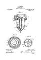
- Figure 5 is a vertical sectional view'of a mechanical agitating machine embodying my invention
- Figure 6 is a transverse sectional view taken substantially on the line 66 of F igure 5';
- Figure 7 is a vertical sectional view of an air operated'agitating machine embodying
- Figure 8 is a plan view of the same; and Figure 9 is a transverse sectional view taken substantially on the line 99 of Figure 7.
- 1 designates the mass, substances or particles to be mixed. Assume, for the purpose of illus- -inertia or greaterfluidity characteristics in connection witlnthe separation of which from their ore my invention has particular utility, present rough surfaces and sharp edges, and are otherwise highly irregular.
- the mass 1 comprising the constituents 2 and 3 is mixed either by moving the surface 4 which surface is of a resilient impression-,-
- the resilient impressionable surface 4 may have a suitable backing as shown at 5 or the entire member maybe formed of the rubber-like substance as desired. It is immaterial in so far as my present invention is concerned whether the resilient impressionable surface or member as the case may be, is moved into engagement with the mass to be mixed or vice versa.
- the particles 3 of less come into contact with the surface 4.
- the motion of the particles 3 is checked at leastmomentarily so that there will fora brief period at least, be a mass of particles 3.in the form of a film upon the surface or parts-of the surface 4 as shown at 6 in Fig. 2.
- Theensuing contact between the heavier particles or objects 2, which particles are ca able of exerting a greater impingement e ect upon the surface 4 due to their greater inertia causes an impressing or indenting of the surface 4 as shown at 7, the particles or objects 2 momentarily imbedding themselves in the. surface 4 at their points .of engagement therewith.
- the mass or film of particles 3 held by the surface 4 are carried in the form of a film or layer into the impressed or imbedded portions 7 effecting a layer or film of particles 3 between the objects 2 and the resilient impressionable surface 4.
- the impressionability of the surface 4 provides a relatively great area of cooperation between the surface 4 and the 189 object 2 upon engagement of the same therewith.
- Flotation processes of ore concentration are based on certain phenomena, namely, the preferential affinity of oil for the metallic or metalliferous parts of the ore and that phenomena which causes an oiled needle to float on water.
- the general practice is to.
- the preferential affinity of the oil for therubber surface as compared with its aflinity-for the gangue and other earthy particles holds the oil to-a greater or less extent against transfer to the gangue particles thereby furthering the natural behavior of the gangue in opposing ad'- hesion of the oil thereto so that the gangue will be thrown off in an unoiled conditlon separating from the metal particles as well understood.
- the agitatin machine 20 is supported upon a concrete pe fdestal or other suitable support 21, in proximity to the separating box or spitzkasten 22 between which and the agitating machine the pulp is circulated.
- the structure of the agitator comprises a lower casing 23, an upper casing 24, these two casings being joined by suitable flanges 25-.-25 and a motor housing 26 super-imposed upon the upper casing 24.
- the lower casing 23 is cylindrical in shape and with the reduced cylindrical portion of the upper casing 24 defines a cylindrical agitating chamber 27.
- the bottom-of the lower casing 23 is formed with a duct 28 having a draina e spout 29 extending therefrom and provi ed with a swinging valve 30 normally closing such spout and providing a drainage outlet for flushing out the agitating chamber when cleaning the machine.
- An annular pulp collecting chamber or trough 31 surrounds the upper part of the agitating chamber 27, this chamber being 1 formed by the radially extending wall 32 projecting from the body of the casing 24, and the vertical wall 33.
- the vertical wall 33 of the chamber 31 is provided with an inwardly turned flange 34 u n which rests the base flange 35 of the upright motor hou'sing 26.
- the agitating chamber 27 extendsup to a point approximately midway of the depth of the chamber 31 and into the trough thus formed between the wall of the agitating chamber and the vertical wall 33 is expelled the froth and pulp after agitation in the chamber 27.
- Disposed about the interior of the chamber 31 are a plurality of radially extending baflles or plates 36 which are adapted to arrest any circulatory motion whence it flows out through the opening 37 and down into the separating box 22.
- a shaft 38 from the motor-'26 extends down into the agitating chamber and has connection through the coupling 39 with the impeller or agitator shaft 40.
- the im-' peller shaft carries an upper agitator 41 and a-lower agitator 42 which preferably take the form of a series of radiating ar'ms rotated at a relatively high speed by the motor 26 to secure a. thorough agitation of the pulp.
- the lower impeller arms 42 are relatively short in order to just clear a series of baffles 43 which-extend inwardly from the wall of the casing 23 as clearly shown in ' Figure 6.
- the upper impeller arms 41 extend outwardly with just sufficient clearance for safety between the ends thereof and the interior surface of thechanrber 27.
- lower impeller arms 42 are preferably dished slightly or curved as shown. in-Figme 6, to impart an upwardpropulsion to the pulp in addition to the circulatory agitation thereof.
- the pulp enters at the lower end of the agitation chamber 27 through the'conduit 45 which leads upfrom a relatively lowpoint in the separating box 22.
- a circulation of pulp is built up between the separating box 22 and theagitator 20, the pulp flowing up through the conduit 45 into the agitating chamber 27 out over the top thereof into the trough 31 and out through the port37 back into the separating box 22. 1
- th'e'pulp is discharged into the separating box 22 after agitation, the me'talliferous' matter is held in suspension by the adhesion of the-oil particles while the gangue or refuse precipitates to the bottom of the separatingbox where it is re-circulated for the further extraction of metals.
- the method of mixing or agitating with which my present invention is concerned, is practiced in the agitator shown-in Figures 5 and 6 by lining the interior. of the agitat ing chamber 27 with a resilient impressionable material 46 which-may be a layer of rubber or other substance having the desired characteristics which rubber provides.
- the surfaces of the agitator arms are. faced or sheathed in a similar material as indicated at 47.
- the projecting baffles 43 mayalso be faced with a similar covering as may the other interior metallic surfaces. have found that with these interior resilient-impressionable surfaces, for the expenditure of a given amount of energy the yield of ore is markedly increased. This is due to the funin I nae
- T have shown my invention as practiced in 'an air agitated flotation machine.
- compressed air injected into the" pulp is used as the agitating agency.
- the casing comprises the main cylindrical shell 50 forming an agitating chamber 51, and an enlarged ,cup shaped portion 52 forming a pulp collecting trough or launder 53.
- the casing 50 carries a conical chamber 54 secured thereto as by means of suitable flanges 55.
- a compressed air nozzle 57 extends up through the conical member 54 and opens into a central agitating'tube 58, which is supported in the agitating chamber 5lby wings 59 extending radially inward from the casing 50 as clearly shownjn Figure 9.-
- a deflecting cap 60' surmounts the, agitating tube 58 and functions to deflect the agitated mass of pulp, as it is impelled upward through the tube 58 out over the top of the tube and back into the main agitating chamber 51.
- the enlarged casing 52 ' isprovided with a small inwardly extending flange 61 adjalcent the floor of the trough 53, and cooperating with this flange is a ring 62 which is supported above the floor of the trough by a downturned flange 63 thereby forming an annular conduit 64: in the bottom of the trough.
- the edge of the ring 62 is spaced from the flange 61 to afiord an annular opening from the conduit into the trough. This opening is covered by a ring of thin fabric 65 which sustains the froth and keeps it out of the conduit 64.
- Air under a slight pressure is admitted to the conduit 64, and this air issuing through the fabric ring 65 throws the froth out of the top of the trough 53 as fast as it settles down along the inclined face of the trough from the lip or edge of the agitating chamber 51.
- a ring 66 is supported in the upper part of the enlarged casing 52 for the purpose of preventing the froth from falling back into the agitating chamber 51.
- the entire inner surface of the agitating chamber 51 is provided with a'resilient impressionable lining 70 substantially as set out in connection with the mechanical tvpe of agitator shown in Figures 5 and 6.
- the deflecting cap 60 surmounting the agitating tube 58' 1s sheathed or faced with a similar by the pulp descending into the bottom of the .conical chamber 54. If deemed desirab-le,the interior of the trough 53 and the deflecting ring 66 may alsobe provided with a resilient impressionable facing.
- The'method of mixin which comprises, settin up a motion of t e particles to be nuixe andchecking the movement of certain of the particles to a greater extent'than other of the particles, to cause imbedding of the other particles in said first particles, and thereby an intimate mixing of the particles.
- the method of mixing which comprises, holding certain of. the particles to be mixed, momentarily at least, and then imbedding other of the particles in the area of the held particles to efi'ectively spread or distribute the constituents throughout "the mass.
- the method of mixing particles of different inertia, or fluidity characteristics which comprises, holding the particles of less inertia or greater fluidity characteristics momentarily at least, and imbedding the particles of greater inertia or lesser fluidity characteristics in the area of the held par-' ticles to eflectively spread or distribute the constituents throughout the mass.
- the method of agitating a liquid and a solid which comprises, engaging the liquid and the solid with a ielding elastic surface.
- the method 0' agitating a fluid mass consisting of particles of material ,ofdifferent freedom of motion which comprises,
- Themethod of agitating a fluid mass consisting of particles of material of different freedom of motion which comprises, engaging the mass with a yielding elastic surface within a space defined by a yielding elastic surface.
- the method of mixing substances of different inertia or fluidity characteristics which comprises, engaging a substance of one characteristic with a resilient .impressionable surface and, imbedding the other substance in the portion of the resilient imimpressionable surface by engaging the a motion of the mass within a pressionable surface engaged by said first substance to 'secure an intimate mixing of the substances.
- the method of applying particles of less inertia and greater fluidity characteristics to the surfaces of particles of greater inertia and less fluidity characteristics which comprises engaging the particles of less inertia. and greater fluidity characteristics with a resilient impressionable surface and imbedding the particles of greater inertia and less fluidity characteristics in said resilient impressionable surface in the area of engagement of said first particles therewith.
- the method of applying globules of oil .to the surface of a metalliferous particle which comprises, engaging the globules of oil with a resilient impressionable surface to effect at least a partial wetting thereof, and imbedding the metalliferous particle in said resilient lmpressionable surface in the area of engagement of the oil therewith to provide a relatively great area of application of the oil to the metalliferous particle.
Description
C. F. SHERWOOD.
METHOD OF MIXING.
APPLICATION HLED APR. 18, 1921.
31. fi lfifigo lPatanted Oct 31, 119220 3 SHEET$SHEET l.
chm
" c F. SHEHWOOI}.
METHOD OF MIXING.
APPLICATION FILED APR. I8, 192l- L3$2SQ Patented Get 31, 1192120 3 SHEETS-SHEET 2.
C. F. SHERWOOD.
METHOD OF MIXING.
APPLICATION FILED APR. 18. 1921.
31. ,kfih o Patented Oct 31, 19220 3 $HEET$SHEET 3- W 60 mg W1 21 I I W' a6 W 65 07 Hi i I 64 5 70 6/ J0 I I. i 65 H v MI 7 Patented (oer, 311, 1922,
barren stares CHARLES 1F. SHERWOOD, OF
SALT LAKE CITY, UTAH, ASSIGNOR TO GEORGE T. HANSON,
or SALT LAKE CITY, UTAH.
mn'rnozo or MIXING.
Application filed April 18,1921, Serial No. 462,3Dt.
To all whom it may concern.
Be it known that I, CHARLES F. Sinai:- wooo, a citizen of the United States, residing at Salt Lake City, in the county of Salt Lake and Statg of Utah, have invented a certain new and useful Improvement in Methods of Mixing, of which vthe following is a full, clear, concise, and exact descript on, reference being had to the accompanying drawings, forming'a part of thls spec1fication.
invention relates to a method of mix- I/lore especially my invention relates to a method of mixing or agitating substances of different inertia or fluidity characteristics which, while having particular utility in connection with the -separation of metals by flotation has a wide range of utrlitynot only for flotation purposes, but for v ar1ous other purposes as well. I do not intend therefore to limit the method of mixing of my invention to aparticular use or purpose.
In mixingisubstances of different inertia characteristics, or different characteristics of fluidity, such as for example, a finely d1- vided abrading material, such as sand and an object to be polished such as a steel ball; a finely divided solid, such as bronze dust or the like and an object to be coated therewith; or a finely divided solid such as for example a metal one and a liquid such as water or a mixture of liquids such as 011 and water for the agitation of which m present invention is particularly adapte great difficulty has heretofore tered in promoting an intimate mixing or mutual and effective intermingling of the constituents.
My invention aims primarily to provide a method of mixin by means of which a' more intimate an more eflicacious mixture or mutual intermingling of the substances or constituent particles will be promoted, particularly a more effective spreading or distribution of the constituents of less inertia to the constituents or particles.
of greater inertia, than has heretofore been attained Taking a articular example, it is well known that the metalliferous particles of ore have a preferential affinity for'oil as distinguished from gangue or earthy materials, and that as explained in Patent No. 1,381,673 granted to me June 14:, 1921, this been encoun-.
phenomenon is employed in recovering the metal from the ore. In mixing or agitating the 011 and pulp together, one of the primary desiderata is to secure a very fine subdlvision of the oil and to spread or distribute effectively the same over all the metalllferous particles which may be in the pulp The more thorough such spread or distribution the greaterthe yield from the ore and the fewer the operations necessary to separate all of the metal from the pulp. The same holds true in the coating or polishing of objects to which I have already made reference, that is, the more effectively the constituents of less inertia are spread or distributed to the objects of greater inertia, the more satisfactory will be the results sought.
According to the theory of my invention,
the substances or constituents to be mixed are engaged with a resilient impressionable surface, which surface holds certain of the constituents, especially those of less inertia, or of a higher degree of fluidity, the partlcles of greater inertia or of alower degree of fluidity momentarily imbedding them selves in such surface by reasonof their greater impinging engagement therewith. A relatively great area of cooperation and a relatively long period of cooperation with such surface is thereby permittedto the end of greater relative motion between the constituents and better mixing or distribution of the constituents evenly and effectivel throughout the mass especially better spread ing of the constituents of less inertia to the surfaces of the objects of greater inertia.
Taking again the case of the separation of metals by. flotation, yield from the pulp as well as the number of operations necessary to separate all of the metalliferous particles therefrom is dependent to a great extent upon the efiectiveness it is well knownthat the with which such particles are oiled during considerable tenacity'against the washing action of the pulp. When the metalliferous particles of the ulp strikethe resilient impressionable sur ace with its film of oil, such particles will .by reason of their greater inertia or impactin impingement imbed themselves momentarily in the oiled surface, the ensuing contact causing a greater or more thorough wetting of the surfaces of the metalliferous particles with the oil than attained heretofore and consistently a better floating or separation of such particles.-
I shall now describe my invention in con- .nection with the accompanying drawings Y impressionable surface and the substances to be'mixed;
Figures 3 and 4 show diagrammatically the mixing of a liquid and a solidin accordance with the method of my invention showing in particular in a diagrammatic manner the utility of the invention in connection with the separation of metals by flotation;
Figure 5 is a vertical sectional view'of a mechanical agitating machine embodying my invention;
Figure 6 is a transverse sectional view taken substantially on the line 66 of F igure 5';
Figure 7 is a vertical sectional view of an air operated'agitating machine embodying,
my invention;
1 Figure 8 is a plan view of the same; and Figure 9 is a transverse sectional view taken substantially on the line 99 of Figure 7.
'I shall now'describe in connection with Figures 1 and 2 of the drawings the fundamental action of mv invention in the mixing of solid particles, substances or constituents of different characteristics of fluidity or different inertia characteristics such as for example a finely divided abrading material, such as sand, or the like, and an object to be polished, such as a steel ball or a finely divided solid such as bronze dust or the like and an object to be coated therewith.
Referring now to Figures 1 and 2, 1 designates the mass, substances or particles to be mixed. Assume, for the purpose of illus- -inertia or greaterfluidity characteristics in connection witlnthe separation of which from their ore my invention has particular utility, present rough surfaces and sharp edges, and are otherwise highly irregular. The mass 1 comprising the constituents 2 and 3 is mixed either by moving the surface 4 which surface is of a resilient impression-,-
able character such as rubberor-other suitable material having'the resiliency and im- 4 pressionability which rubber provides, into engagement with the mass, in the nature of a whipper, beater or agitator or by moving the mass into impacting engagement with the surface 4. The resilient impressionable surface 4 may have a suitable backing as shown at 5 or the entire member maybe formed of the rubber-like substance as desired. It is immaterial in so far as my present invention is concerned whether the resilient impressionable surface or member as the case may be, is moved into engagement with the mass to be mixed or vice versa. v 2
Upon the relative motion thereby set up between the rubber-like surface 4 and the constituents 2 and 3, the particles 3 of less come into contact with the surface 4. Upon contact with the surface 4 the motion of the particles 3 is checked at leastmomentarily so that there will fora brief period at least, be a mass of particles 3.in the form of a film upon the surface or parts-of the surface 4 as shown at 6 in Fig. 2. Theensuing contact between the heavier particles or objects 2, which particles are ca able of exerting a greater impingement e ect upon the surface 4 due to their greater inertia causes an impressing or indenting of the surface 4 as shown at 7, the particles or objects 2 momentarily imbedding themselves in the. surface 4 at their points .of engagement therewith. Upon such imbedding of the particles 2, the mass or film of particles 3 held by the surface 4 are carried in the form of a film or layer into the impressed or imbedded portions 7 effecting a layer or film of particles 3 between the objects 2 and the resilient impressionable surface 4. As shown in Figure 2 the impressionability of the surface 4 provides a relatively great area of cooperation between the surface 4 and the 189 object 2 upon engagement of the same therewith. This relatively great area of cooperation between the surface 4 and the object 2 effects an equally great engagement or contact of the particles 3 moved in the form of a layer or film into the impression ahead of the object 2, with the surface of such object whether it be regular as shown or irregular"=and consistently a better or more thorough distribution of the particles 3 to the surfaces of the objects 2. The result is a better mixing or distribution of the constituentsevenly through the mass or medium than has heretofore been attained. As soon as the impact of the particle or object 2 is taken up, the particle is thrown off because of the resilientcharacter of the rubber-like surface 4. The surface 4 is thus self-cleaning and always ready to repeat the operation. The engagement of the particles or constituents to be mixed with a resilient impressionable surface clearly effects a better distribution of the particles through the mass and a greater relative movement between the particles than possible heretofore.
These provisions are highly advantageous in the coating or polishing of an object for example, in that the result sought is better than heretofore possible and it is had with fewer operations, or in other words, with less mixing of the particles than heretofore necessary.
I will now describe the utility of the fundamental action of my invention in connection with the separation of metals by flotation as illustrating the eflicacious or mutual and effectiveintermingling of a finely divided solid, such as for example, a metal one, and a liquid such as water or a mixture of liquid such as oil and. water, that is bad thereby.
Flotation processes of ore concentration are based on certain phenomena, namely, the preferential affinity of oil for the metallic or metalliferous parts of the ore and that phenomena which causes an oiled needle to float on water. The general practice is to.
create a froth or foam bearing the oil treated metallic or metalliferous particles, which foam or froth may be brushed off, floated off or otherwise removed. My invention is not immediately concerned with such phase of the flotation process nor is it limited to the mixing of the particular metallic and liquid substances treated'by such processes. The substances which, will be hereinafter referred to simply illustrate the fundamental action which takes place upon the mixing of a liquid and a solid in accordance with my invention. The particular mass referred to is one which I find is mixed in a highly advantageous manner with the method of my invention.
Referring now to Figures 3 and 4 where l[ have shown diagrammatically justsufiicient apparatus toillustrate the fundamental action of my invention, the vessel 10 1s filled to about the level of the line 11 with the crushed ore, water and a little oil. Relative moved into impacting engagement with such lining either by shaking the vessel violently or otherwise efiecting such engagement with the lining or such a lining may be used in conjunction with the resilient impressionable surface 12 or the surface 12 may be used alone as illustrated.
In either case, upon or during the relative motion set up between the resilient impressionable surface and the mass 14 within the vessel 10 the particles of oil 15 in the mass, come into contact with the rubber-like surface 12 so that for each contact of a globule of oil with. the rubber, there is a wetting of the surface as shown at 16 in Figure 4 whereby for a brief period of time at least, there is a film of oil upon a part of the resilient impressionable surface. Thereafter, let us assume that a metalliferbus particle designated 17 in Figures 3. and 4 strikes the surface 12 at the point where the film 16 of oil is held. The ensuing contact between the relatively heavy metalliferous particle causes a relatively greater wetting of the surface of such particle with the oil than heretofore attained because the rubber or re silient impressionable surface permits the particle 17 to imbed itself momentarily therein. The momentary imbedding of the lar formation with the result that the particles 17 are quickly and effectively oiled and rise to the top of the mass as froth from where they may be removed in any suitable or desired manner. The yield from the ore is thereby increased and the number of operations necessary to separate all of the metalliferous particles from the pulp is decreased.
In find that the rubber-like surface tends to hold the oil to a considerable degree and that then this oil is transferred to the metalliferous particles by the relatively great contact had. The afiinity between the oil and the rubber prevents its being readily -wiped away by the violent movement of the water and gangue or earthy particles in the erous particle is taken up, the .thoroughly olled particle is thrown off because of the resilient character of the rubber and the .rubber surface is thus self-cleaning and alparticles being then thrown off by the -resilient. character of the rubber as soon as such impact is taken'up. The preferential affinity of the oil for therubber surface as compared with its aflinity-for the gangue and other earthy particles holds the oil to-a greater or less extent against transfer to the gangue particles thereby furthering the natural behavior of the gangue in opposing ad'- hesion of the oil thereto so that the gangue will be thrown off in an unoiled conditlon separating from the metal particles as well understood.
I shall now give a brief description of the structure and operation of a conventional type of agitator embodying the fundamental action of my invention so as to clearly conveythe manner in which the method of mixing of my invention may be embodied in such apparatus.
Referring to Figures 5 and 6 the agitatin machine 20 is supported upon a concrete pe fdestal or other suitable support 21, in proximity to the separating box or spitzkasten 22 between which and the agitating machine the pulp is circulated. The structure of the agitator comprises a lower casing 23, an upper casing 24, these two casings being joined by suitable flanges 25-.-25 and a motor housing 26 super-imposed upon the upper casing 24. The lower casing 23 is cylindrical in shape and with the reduced cylindrical portion of the upper casing 24 defines a cylindrical agitating chamber 27. The bottom-of the lower casing 23 is formed with a duct 28 having a draina e spout 29 extending therefrom and provi ed with a swinging valve 30 normally closing such spout and providing a drainage outlet for flushing out the agitating chamber when cleaning the machine.
An annular pulp collecting chamber or trough 31 surrounds the upper part of the agitating chamber 27, this chamber being 1 formed by the radially extending wall 32 projecting from the body of the casing 24, and the vertical wall 33. The vertical wall 33 of the chamber 31 is provided with an inwardly turned flange 34 u n which rests the base flange 35 of the upright motor hou'sing 26. The agitating chamber 27 extendsup to a point approximately midway of the depth of the chamber 31 and into the trough thus formed between the wall of the agitating chamber and the vertical wall 33 is expelled the froth and pulp after agitation in the chamber 27. Disposed about the interior of the chamber 31 are a plurality of radially extending baflles or plates 36 which are adapted to arrest any circulatory motion whence it flows out through the opening 37 and down into the separating box 22.
A shaft 38 from the motor-'26, extends down into the agitating chamber and has connection through the coupling 39 with the impeller or agitator shaft 40. The im-' peller shaft carries an upper agitator 41 and a-lower agitator 42 which preferably take the form of a series of radiating ar'ms rotated at a relatively high speed by the motor 26 to secure a. thorough agitation of the pulp. The lower impeller arms 42 are relatively short in order to just clear a series of baffles 43 which-extend inwardly from the wall of the casing 23 as clearly shown in 'Figure 6. The upper impeller arms 41 extend outwardly with just sufficient clearance for safety between the ends thereof and the interior surface of thechanrber 27. The
- The pulp enters at the lower end of the agitation chamber 27 through the'conduit 45 which leads upfrom a relatively lowpoint in the separating box 22. By the operation of the agitator, a circulation of pulp is built up between the separating box 22 and theagitator 20, the pulp flowing up through the conduit 45 into the agitating chamber 27 out over the top thereof into the trough 31 and out through the port37 back into the separating box 22. 1 When th'e'pulp" is discharged into the separating box 22 after agitation, the me'talliferous' matter is held in suspension by the adhesion of the-oil particles while the gangue or refuse precipitates to the bottom of the separatingbox where it is re-circulated for the further extraction of metals.
The method of mixing or agitating with which my present invention is concerned, is practiced in the agitator shown-in Figures 5 and 6 by lining the interior. of the agitat ing chamber 27 with a resilient impressionable material 46 which-may be a layer of rubber or other substance having the desired characteristics which rubber provides. The surfaces of the agitator arms are. faced or sheathed in a similar material as indicated at 47. The projecting baffles 43 mayalso be faced with a similar covering as may the other interior metallic surfaces. have found that with these interior resilient-impressionable surfaces, for the expenditure of a given amount of energy the yield of ore is markedly increased. This is due to the funin I nae
damental action of my invention which has already been clearly set out, i. e., the greater relative motion secured between the particles, the more thorough application of the oil to the .metal particles caused by the greater area of contact which is secured when a particle imbeds itself momentarily in either of the interior resilient impressionable surfaces which it might engage and the lower co-eflicient of friction by reason of these wet or oiled rubber-like surfaces, to-
gether with the resulting greater freedom of motion provided. I
In Figures 7, 8 and 9, T have shown my invention as practiced in 'an air agitated flotation machine. In this arrangement compressed air injected into the" pulp, is used as the agitating agency. The casingcomprises the main cylindrical shell 50 forming an agitating chamber 51, and an enlarged ,cup shaped portion 52 forming a pulp collecting trough or launder 53. At its lower end the casing 50 carries a conical chamber 54 secured thereto as by means of suitable flanges 55. A compressed air nozzle 57 extends up through the conical member 54 and opens into a central agitating'tube 58, which is supported in the agitating chamber 5lby wings 59 extending radially inward from the casing 50 as clearly shownjn Figure 9.- A deflecting cap 60' surmounts the, agitating tube 58 and functions to deflect the agitated mass of pulp, as it is impelled upward through the tube 58 out over the top of the tube and back into the main agitating chamber 51. The enlarged casing 52 'isprovided with a small inwardly extending flange 61 adjalcent the floor of the trough 53, and cooperating with this flange is a ring 62 which is supported above the floor of the trough by a downturned flange 63 thereby forming an annular conduit 64: in the bottom of the trough. The edge of the ring 62 is spaced from the flange 61 to afiord an annular opening from the conduit into the trough. This opening is covered by a ring of thin fabric 65 which sustains the froth and keeps it out of the conduit 64. Air under a slight pressure is admitted to the conduit 64, and this air issuing through the fabric ring 65 throws the froth out of the top of the trough 53 as fast as it settles down along the inclined face of the trough from the lip or edge of the agitating chamber 51. A ring 66 is supported in the upper part of the enlarged casing 52 for the purpose of preventing the froth from falling back into the agitating chamber 51.
The entire inner surface of the agitating chamber 51 is provided with a'resilient impressionable lining 70 substantially as set out in connection with the mechanical tvpe of agitator shown in Figures 5 and 6. The deflecting cap 60 surmounting the agitating tube 58' 1s sheathed or faced with a similar by the pulp descending into the bottom of the .conical chamber 54. If deemed desirab-le,the interior of the trough 53 and the deflecting ring 66 may alsobe provided with a resilient impressionable facing.
While I have described my improved method of mixing in connection with the mixing of certain substances or. constituents the utility of the invention is not limited to the mixing of such particular substances, but is adapted for mixing any substances embodying the characteristics which are required to secure the fundamental actionwhich I have disclosed. I refer to the resilient impressionable surfaces as being rubberlike, to ing the desired characteristics which rubber provides.
As I have already stated, itis immaterial whether the resilient impressionable surface moves against the substance or mass to be mixed or vice versa. Both actions have been explained in connection with the drawings.
I claim:
1.- The method of diflerent inertia or fluidity characteristics which comprises, effecting dmpacting enagement of the particles with a resilient impressionable surface.
2. The method of mixing which comeffecting impactin engagement of prises,
with a resilient imthe particles to be mixed pressionable surface. 3. The'method of mixin which comprises, settin up a motion of t e particles to be nuixe andchecking the movement of certain of the particles to a greater extent'than other of the particles, to cause imbedding of the other particles in said first particles, and thereby an intimate mixing of the particles.
mixing substances of designate broadly a substance hav- 4.. The method of mixing which comprises, holding certain of. the particles to be mixed, momentarily at least, and then imbedding other of the particles in the area of the held particles to efi'ectively spread or distribute the constituents throughout "the mass.
5. The method of mixing particles of different inertia, or fluidity characteristics which comprises, holding the particles of less inertia or greater fluidity characteristics momentarily at least, and imbedding the particles of greater inertia or lesser fluidity characteristics in the area of the held par-' ticles to eflectively spread or distribute the constituents throughout the mass.
6. The method of mixing a liquid and a 8. The method of agitating a fluid mass,
consisting of particles of material of different freedom of motion which comprises, effecting impacting contact of a yieldable impacting surface with the mass. y 9. The method of agitating'which comprises, effecting free impacting agitating engagement of the mass to be agitated with an agitating surface of rubber like characteristics.
10. The method of agitating a liquid and a solid which comprises, engaging the liquid and the solid with a ielding elastic surface. 11. The method 0' agitating a fluid mass consisting of particles of material ,ofdifferent freedom of motion which comprises,
- setting u space de ned by a resilient impressionable surface.
12. Themethod of agitating a fluid mass consisting of particles of material of different freedom of motion which comprises, engaging the mass with a yielding elastic surface within a space defined by a yielding elastic surface.
13. The method of mixing substances of different inertia or fluidity characteristics which comprises, engaging a substance of one characteristic with a resilient .impressionable surface and, imbedding the other substance in the portion of the resilient imimpressionable surface by engaging the a motion of the mass within a pressionable surface engaged by said first substance to 'secure an intimate mixing of the substances.
14. The method of mixing a liquid and a solid which comprises Wetting a resilient liquid therewith, and imbedding the solid in the wetted area of said resilient impressionable surface to secure an intimate mixing of the substances.
15. The method of applying particles of less inertia and greater fluidity characteristics to the surfaces of particles of greater inertia and less fluidity characteristics which comprises engaging the particles of less inertia. and greater fluidity characteristics with a resilient impressionable surface and imbedding the particles of greater inertia and less fluidity characteristics in said resilient impressionable surface in the area of engagement of said first particles therewith.
16. The method of applying globules of oil .to the surface of a metalliferous particle which comprises, engaging the globules of oil with a resilient impressionable surface to effect at least a partial wetting thereof, and imbedding the metalliferous particle in said resilient lmpressionable surface in the area of engagement of the oil therewith to provide a relatively great area of application of the oil to the metalliferous particle.
17. The method of applying a'liquid to the surface of a solid which comprises, holding the liquid in the form of a film on a resilient impressionable surface, and imbedding the solid in the liquid film and resilient impressionable surface to secure a relatively great area of application of the liquid to the solid. i
In Witness whereof, I hereunto subscribe my name this 18th da of March, 1921.
CHARLIE F. SHERWOOD.
Priority Applications (1)
| Application Number | Priority Date | Filing Date | Title |
|---|---|---|---|
| US462354A US1434232A (en) | 1921-04-18 | 1921-04-18 | Method of mixing |
Applications Claiming Priority (1)
| Application Number | Priority Date | Filing Date | Title |
|---|---|---|---|
| US462354A US1434232A (en) | 1921-04-18 | 1921-04-18 | Method of mixing |
Publications (1)
| Publication Number | Publication Date |
|---|---|
| US1434232A true US1434232A (en) | 1922-10-31 |
Family
ID=23836128
Family Applications (1)
| Application Number | Title | Priority Date | Filing Date |
|---|---|---|---|
| US462354A Expired - Lifetime US1434232A (en) | 1921-04-18 | 1921-04-18 | Method of mixing |
Country Status (1)
| Country | Link |
|---|---|
| US (1) | US1434232A (en) |
Cited By (8)
| Publication number | Priority date | Publication date | Assignee | Title |
|---|---|---|---|---|
| US2664349A (en) * | 1948-08-07 | 1953-12-29 | Electro Chimie Metal | Method of precipitating solid particles from a suspension of the particles in a liquor |
| US2678873A (en) * | 1948-08-07 | 1954-05-18 | Electro Chimie Metal | Precipitator |
| US2820597A (en) * | 1954-01-04 | 1958-01-21 | Pettibone Mulliken Corp | Hammer mills with resilient seal |
| US2983454A (en) * | 1959-01-07 | 1961-05-09 | Jr William Podmore | Method of vibratory grinding and apparatus therefor |
| US4186087A (en) * | 1977-04-22 | 1980-01-29 | Director-General Of Agency Of Industrial Science And Technology | Method and apparatus for separating substances from liquids by flotation using bubbles |
| WO1993022061A1 (en) * | 1992-04-30 | 1993-11-11 | Norman Wilson | Vortex flotation cell |
| US5314076A (en) * | 1991-02-04 | 1994-05-24 | Gie Anjou-Recherche | Installation for the mixing of two fluid phases by mechanical stirring, notably for the treatment of water by transfer of oxidizing gas, and use of such an installation |
| US5399261A (en) * | 1990-05-31 | 1995-03-21 | Gie Anjou-Recherche | Installation for the treatment of flows of liquids with monophase contactor and recirculating-degassing device |
-
1921
- 1921-04-18 US US462354A patent/US1434232A/en not_active Expired - Lifetime
Cited By (8)
| Publication number | Priority date | Publication date | Assignee | Title |
|---|---|---|---|---|
| US2664349A (en) * | 1948-08-07 | 1953-12-29 | Electro Chimie Metal | Method of precipitating solid particles from a suspension of the particles in a liquor |
| US2678873A (en) * | 1948-08-07 | 1954-05-18 | Electro Chimie Metal | Precipitator |
| US2820597A (en) * | 1954-01-04 | 1958-01-21 | Pettibone Mulliken Corp | Hammer mills with resilient seal |
| US2983454A (en) * | 1959-01-07 | 1961-05-09 | Jr William Podmore | Method of vibratory grinding and apparatus therefor |
| US4186087A (en) * | 1977-04-22 | 1980-01-29 | Director-General Of Agency Of Industrial Science And Technology | Method and apparatus for separating substances from liquids by flotation using bubbles |
| US5399261A (en) * | 1990-05-31 | 1995-03-21 | Gie Anjou-Recherche | Installation for the treatment of flows of liquids with monophase contactor and recirculating-degassing device |
| US5314076A (en) * | 1991-02-04 | 1994-05-24 | Gie Anjou-Recherche | Installation for the mixing of two fluid phases by mechanical stirring, notably for the treatment of water by transfer of oxidizing gas, and use of such an installation |
| WO1993022061A1 (en) * | 1992-04-30 | 1993-11-11 | Norman Wilson | Vortex flotation cell |
Similar Documents
| Publication | Publication Date | Title |
|---|---|---|
| US4177608A (en) | Finishing apparatus embodying improved seal and method | |
| US1434232A (en) | Method of mixing | |
| US2521152A (en) | Mineral separation process | |
| US1124855A (en) | Ore-separatory apparatus. | |
| US2371837A (en) | Apparatus for pulping and screening papermaking materials | |
| US2226170A (en) | Flotation of materials | |
| US1895505A (en) | Process of classifying materials | |
| US2477948A (en) | Sand scrubber | |
| US1285061A (en) | Flotation apparatus. | |
| US1374499A (en) | Flotation apparatus | |
| US1937190A (en) | Apparatus for agitating fluid masses and separating materials | |
| US2132195A (en) | Apparatus for the recovery of precious metals such as gold | |
| US1224138A (en) | Coal-washing and ore concentration. | |
| US631680A (en) | Mineral-extracting machine. | |
| US2243302A (en) | Means of treating liquids | |
| USRE16674E (en) | Method and apparatus for sep abating materials of different | |
| US4039433A (en) | Process and apparatus for recovering metal from soil | |
| US1350605A (en) | Flotation apparatus | |
| US2733809A (en) | Separation | |
| US2422203A (en) | Specific gravity separation of solids in liquid suspension | |
| US2493049A (en) | Ore scrubbing apparatus | |
| US1366767A (en) | John m | |
| US1124853A (en) | Ore-concentrating apparatus. | |
| US1821684A (en) | Rotary pulp screen | |
| US697353A (en) | Apparatus for screening crushed ores or other materials. |