US104389A - Improvement in oil-cabinets - Google Patents
Improvement in oil-cabinets Download PDFInfo
- Publication number
- US104389A US104389A US104389DA US104389A US 104389 A US104389 A US 104389A US 104389D A US104389D A US 104389DA US 104389 A US104389 A US 104389A
- Authority
- US
- United States
- Prior art keywords
- oil
- pump
- tank
- nozzle
- cans
- Prior art date
- Legal status (The legal status is an assumption and is not a legal conclusion. Google has not performed a legal analysis and makes no representation as to the accuracy of the status listed.)
- Expired - Lifetime
Links
- 210000001331 Nose Anatomy 0.000 description 8
- 206010022114 Injury Diseases 0.000 description 4
- 102100017923 ACOT12 Human genes 0.000 description 2
- 101710008266 ACOT12 Proteins 0.000 description 2
- 210000002816 Gills Anatomy 0.000 description 2
- 210000003739 Neck Anatomy 0.000 description 2
- 241000283898 Ovis Species 0.000 description 2
- 150000001768 cations Chemical class 0.000 description 2
- 238000007599 discharging Methods 0.000 description 2
- 230000005484 gravity Effects 0.000 description 2
- 230000001939 inductive effect Effects 0.000 description 2
- 239000007788 liquid Substances 0.000 description 2
- 230000002633 protecting Effects 0.000 description 2
- 239000010902 straw Substances 0.000 description 2
- ATJFFYVFTNAWJD-UHFFFAOYSA-N tin hydride Chemical compound [Sn] ATJFFYVFTNAWJD-UHFFFAOYSA-N 0.000 description 2
- 239000002699 waste material Substances 0.000 description 2
Images

Classifications
-
- B—PERFORMING OPERATIONS; TRANSPORTING
- B67—OPENING, CLOSING OR CLEANING BOTTLES, JARS OR SIMILAR CONTAINERS; LIQUID HANDLING
- B67D—DISPENSING, DELIVERING OR TRANSFERRING LIQUIDS, NOT OTHERWISE PROVIDED FOR
- B67D7/00—Apparatus or devices for transferring liquids from bulk storage containers or reservoirs into vehicles or into portable containers, e.g. for retail sale purposes
- B67D7/06—Details or accessories
- B67D7/32—Arrangements of safety or warning devices; Means for preventing unauthorised delivery of liquid
- B67D7/34—Means for preventing unauthorised delivery of liquid
- B67D7/344—Means for preventing unauthorised delivery of liquid by checking a correct coupling or coded information
- B67D7/348—Means for preventing unauthorised delivery of liquid by checking a correct coupling or coded information by interrogating an information transmitter, e.g. a transponder
-
- B—PERFORMING OPERATIONS; TRANSPORTING
- B67—OPENING, CLOSING OR CLEANING BOTTLES, JARS OR SIMILAR CONTAINERS; LIQUID HANDLING
- B67D—DISPENSING, DELIVERING OR TRANSFERRING LIQUIDS, NOT OTHERWISE PROVIDED FOR
- B67D7/00—Apparatus or devices for transferring liquids from bulk storage containers or reservoirs into vehicles or into portable containers, e.g. for retail sale purposes
- B67D7/06—Details or accessories
- B67D7/58—Arrangements of pumps
- B67D7/68—Arrangements of pumps submerged in storage tank or reservoir
-
- B—PERFORMING OPERATIONS; TRANSPORTING
- B67—OPENING, CLOSING OR CLEANING BOTTLES, JARS OR SIMILAR CONTAINERS; LIQUID HANDLING
- B67D—DISPENSING, DELIVERING OR TRANSFERRING LIQUIDS, NOT OTHERWISE PROVIDED FOR
- B67D7/00—Apparatus or devices for transferring liquids from bulk storage containers or reservoirs into vehicles or into portable containers, e.g. for retail sale purposes
- B67D7/06—Details or accessories
- B67D7/84—Casings, cabinets or frameworks; Trolleys or like movable supports
-
- F—MECHANICAL ENGINEERING; LIGHTING; HEATING; WEAPONS; BLASTING
- F16—ENGINEERING ELEMENTS AND UNITS; GENERAL MEASURES FOR PRODUCING AND MAINTAINING EFFECTIVE FUNCTIONING OF MACHINES OR INSTALLATIONS; THERMAL INSULATION IN GENERAL
- F16N—LUBRICATING
- F16N31/00—Means for collecting, retaining, or draining-off lubricant in or on machines or apparatus
- F16N31/002—Drain pans
Definitions
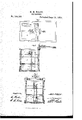
- Figure l is a top view of my said cabinet, with the coverV turned back. f. Y
- Figure 2 is a vertical and central section, taken through the tell-tale and discharge ⁇ pr eduction-pipe of the pump.
- Figure 3 is another vertical section, taken on' the line :i: i: of iig. l.
- A denotes a rectangular' box or case, provided with a cover, B, hinged thereto.
- a chamber or compartinenn'l Disposed above the said tank is a chamber or compartinenn'l), which is provided with two shelves, E F, the former being provided witlra series of holes,4
- the shelf F is corrugated or formed with channels running longitudinally, and terminating at one end in a series of holes, b.
- the object of the latter shelf is the purpose of supporting themwhile being drained,
- I is a tell-tale, which extends down into the rcsvoir C, and has a hollow ball or float, d upon its lower en
- a stop, f, ' is disposed, which prevents the tell-tale froir having a too great rapge of motion.
- tin ftell-tale 7 is not to showwhat amount of liquid then may be in the tank, but to indicatewhen it getV too low and the tank needs replenishing.
- the tube o of the said tell-tale operates as i vent, to allow of the escape of air while the tank i. being filled.
- a force-pump, F' is' disposed, K being the pump-barrel thereof.
- L is a weighted piston, provided with a rod, g, and handle, 7i'.
- Ovis au adjustable stand or can-supporter which is attached by means of an arm, h', to a slider, P, which is arranged concentrically around the vupper upright portion of the pipe M.
- said slider is surmoupted by a coiled spring, la, one end of which is attached to lthe Slider. the ⁇ other end beingfastened to the said pipe.
- Q is an annular guide or ccntralizer, which is supported by two arms, l, affixed to the sides of the pump-nozzle, one of which is seen in fig. 2, the said ccntralizer being arranged conccntrically with respect to the base of the pump-nose, in orderthat, when the mouth of a can is introduced into the centralizer, the oil l or Huid ejected from the nose ofthe pn mp may enter the mouth ofthe can axially,iand thus prevent any overflow or waste of. the oil or uid.
- the object oi' making the can-supporter adjustable is, ⁇ to enableit to receive and hold cans of diderent sizes and maintain them in' their proper positions, with respect to the nose of the pump, while being iilled.
- This applip cation and arrangement of the coiled spring such not only Serves to support the stand while a can is being filled, but enables it (such can) to'be readily removed from or applied .to the stand, as may be dcsii-able.
- 1t is a measuring or check-chain, one end of which is attached to the handle of the piston, and the other to the top of the reservoir, as seen in iig. 1.
- the ob- -ject of this chain is to regulate the amount of oil received into the pump-barrel at each upward move# nient of the piston, in accordance ⁇ with the capacity of the can to be lled; that is tosay, if each oil-can to be lledholds one pint, we must raise the piston a sulicient distance to allow a pint to flow into the pump-barrel.
- Each link of the said chainniay be supposed to in dicatc a measure for a certain ixed quantity, for instance, a gill, or a pint, as may bc desirable. Having adjusted the chain to the desired point to accord with the capacity of the can, we have only to raise the piston until arrested by the chaiuto causethe desired amount of oil to enter the pump-barrel.
- T is a device for clearing the ⁇ nozzles of the cans of any extraneous matter, and consists of a pointed wire attached to the cover B, as shown in tig. 1.
- the said ⁇ cleaner is provided with a shield or l ⁇ guard on, whose object is to prot-ect it from injury, as well as from doing injury.
- U is a shelf, which is arranged ou the cover B, and with respect to the clearer T, as shown iu the drawing.
- This shelf is provided with a series of holes, n, for receiving the nozzles of the cans to he filled.
- the desired quantity is to be poured into the compartment or sink 1),'from whence it will flow into the reservoir or tank through the orifices G and H.
- the reservoir having been supplied with oil the operation of' filling the oil-cans is as follows:
- the cans to be filled are first to have their nozzles removed, and the nozzle-clearer passed through them. They are then to be placed in the orifices in the nozzle-receiving shelf U, and their cans to be placed mouth downward within the holes in the shelf E.
- theoilcaus After being properly drained, theoilcaus are to be filled with oil by placing cach onein succession on the stand O, and so that its mouth shall enter the centralizer Q, and next manipulating the pump, as before described. ⁇ Vhen filled, they are to be removed from the stand, the nozzle oi' each to be again inserted in the mouth of its can, when they are ready for use, and may be placed on the shelf E.
- An oil-cabinet substantially as described, the same consistinl of a reservoir or tank, C, and a compartment. or sink, D, provided with a pump, a stand or can-supporter, 0, and tell-tale, constructedas specified, all combined, arranged, and operating together iu manner and for the purpose hereinbefore specified.
- An oil-cabinet consisting of a reservoir or tank, C, and a compartment or sink, D, provided with a pump, a cau-supporter, O, and waste-receiving orifice G, all constructed, combined, and arranged together in manner aud for the purpose hcreiubeforc set forth.
- the nozzle-clearer aud its shield, when constructed as described, and applied to the cover of the case, as set forth.
Landscapes
- Engineering & Computer Science (AREA)
- Mechanical Engineering (AREA)
- General Engineering & Computer Science (AREA)
- Earth Drilling (AREA)
Description
M. H. WILEY.
' Tapi @@QQQ Tm: muys Firms co.. PNUmLITuo., wAsMINuToN. DJ:
` fattura Straw para erpa- MOSES HLWILEY, OE EAST BOSTON, MASSACHUSETTS, ASSIGNOR To HIMTSELE,
Y THOMAS MILLER', AND JOHN 4n. E'. LANG, OE BOSTON, MASSACHUSETTS.
Lette-rs Patent No. 104,389, (Za-ted June 14, 18.70.
v IMPROVEMENT IN OIL-GABINETE.
The Schedule referred t in. these Letters Patent and naklng part of the same To all to who-mthesc presents may come: Q
`Be it known that I, MOSES' H. WILEY, ofEast Boston, in the county of Suffolk and State of Massachusetts, have invented a new and useful Oil-Cabinet for Factories, 85o. and I do hereby declare the same to be fully describedin theibllowing speciticatiou, and represented in the accompanying drawing, of which;
Figure l is a top view of my said cabinet, with the coverV turned back. f. Y
Figure 2is a vertical and central section, taken through the tell-tale and discharge `pr eduction-pipe of the pump. a
Figure 3 is another vertical section, taken on' the line :i: i: of iig. l.
In the said drawing-L A denotes a rectangular' box or case, provided with a cover, B, hinged thereto.
Within the lower part of the saidcase is an oil-reservoir or tank, C. i
Disposed above the said tank is a chamber or compartinenn'l), which is provided with two shelves, E F, the former being provided witlra series of holes,4
a a, Sto., to receive the inverted necks of cil-cans, for
preparatory to being iillegd,`
The shelf F is corrugated or formed with channels running longitudinally, and terminating at one end in a series of holes, b. The object of the latter shelf is the purpose of supporting themwhile being drained,
i to support the cans after they may have been filled surface of the tank, and will flow down into the interior thereof through the orice H.
I is a tell-tale, which extends down into the rcsvoir C, and has a hollow ball or float, d upon its lower en Upon-the stem e of the floator tell-tale, a stop, f, 'is disposed, which prevents the tell-tale froir having a too great rapge of motion. 'lhe object of tin ftell-tale 7 is not to showwhat amount of liquid then may be in the tank, but to indicatewhen it getV too low and the tank needs replenishing. Further more, the tube o of the said tell-tale operates as i vent, to allow of the escape of air while the tank i. being filled. i
Within the said reservoir C, and aixed to the bottom thereof', a force-pump, F', is' disposed, K being the pump-barrel thereof.
L is a weighted piston, provided with a rod, g, and handle, 7i'.
M `denotes the eduction-pipe, and N the discharging end or nose of the pump, the Said barrel and pipe being respectively provided with induction and eduction-valvcs in the ordinary manner.
' Ovis au adjustable stand or can-supporter, which is attached by means of an arm, h', to a slider, P, which is arranged concentrically around the vupper upright portion of the pipe M. Ilhe said slider is surmoupted by a coiled spring, la, one end of which is attached to lthe Slider. the `other end beingfastened to the said pipe.
Q is an annular guide or ccntralizer, which is supported by two arms, l, affixed to the sides of the pump-nozzle, one of which is seen in fig. 2, the said ccntralizer being arranged conccntrically with respect to the base of the pump-nose, in orderthat, when the mouth of a can is introduced into the centralizer, the oil l or Huid ejected from the nose ofthe pn mp may enter the mouth ofthe can axially,iand thus prevent any overflow or waste of. the oil or uid. The object oi' making the can-supporter adjustable is,` to enableit to receive and hold cans of diderent sizes and maintain them in' their proper positions, with respect to the nose of the pump, while being iilled. By this applip cation and arrangement of the coiled spring, such not only Serves to support the stand while a can is being filled, but enables it (such can) to'be readily removed from or applied .to the stand, as may be dcsii-able.
1t is a measuring or check-chain, one end of which is attached to the handle of the piston, and the other to the top of the reservoir, as seen in iig. 1. The ob- -ject of this chain is to regulate the amount of oil received into the pump-barrel at each upward move# nient of the piston, in accordance `with the capacity of the can to be lled; that is tosay, if each oil-can to be lledholds one pint, we must raise the piston a sulicient distance to allow a pint to flow into the pump-barrel.
Each link of the said chainniay be supposed to in dicatc a measure for a certain ixed quantity, for instance, a gill, or a pint, as may bc desirable. Having adjusted the chain to the desired point to accord with the capacity of the can, we have only to raise the piston until arrested by the chaiuto causethe desired amount of oil to enter the pump-barrel. If,no\v, we release our hold of the piston-handle, the piston, being heavily weighted, will rapidly descend by the action of gravity, and will force the oil out ofthe pump-` barrcl into the cduction-pipe, and thereby force alike quantity from the eduction-pipc through the nose of the pump int-o the oil-can placed under the same.
T is a device for clearing the `nozzles of the cans of any extraneous matter, and consists of a pointed wire attached to the cover B, as shown in tig. 1. The said` cleaner is provided with a shield or l`guard on, whose object is to prot-ect it from injury, as well as from doing injury.
U is a shelf, which is arranged ou the cover B, and with respect to the clearer T, as shown iu the drawing. This shelf is provided with a series of holes, n, for receiving the nozzles of the cans to he filled.
vIn supplying the tank or reservoir with oil, the desired quantity is to be poured into the compartment or sink 1),'from whence it will flow into the reservoir or tank through the orifices G and H.
The reservoir having been supplied with oil, the operation of' filling the oil-cans is as follows:
The cans to be filled are first to have their nozzles removed, and the nozzle-clearer passed through them. They are then to be placed in the orifices in the nozzle-receiving shelf U, and their cans to be placed mouth downward within the holes in the shelf E.
After being properly drained, theoilcaus are to be filled with oil by placing cach onein succession on the stand O, and so that its mouth shall enter the centralizer Q, and next manipulating the pump, as before described. \Vhen filled, they are to be removed from the stand, the nozzle oi' each to be again inserted in the mouth of its can, when they are ready for use, and may be placed on the shelf E.
I would remark that I do not claim brondi y limiting or controlling the stroke of a pistou by means of a chain, or its equivalent, as'I am aware that such is not new. Neither do l claim the invention, 01 any part thereof, as shown in Letters Patent No. 21,814, as my invention differs materially therefrom Having described my invention,
lVhat I claim is as follows:
1. An oil-cabinet, substantially as described, the same consistinl of a reservoir or tank, C, and a compartment. or sink, D, provided with a pump, a stand or can-supporter, 0, and tell-tale, constructedas specified, all combined, arranged, and operating together iu manner and for the purpose hereinbefore specified.
2. An oil-cabinet, consisting of a reservoir or tank, C, and a compartment or sink, D, provided with a pump, a cau-supporter, O, and waste-receiving orifice G, all constructed, combined, and arranged together in manner aud for the purpose hcreiubeforc set forth.
3. The combination of the adjustable stand or cansupporter O with the discharge-pipe or nozzle of the pump, substantially as and for the purpose hereinbefore specified.
y 4. The combination and arrangement of the stand O and the centralizer Q with the discharge or nozzle of the pump, in. manner and for the purpose set forth.
5. Providing the piston of a pump with'meaus or devices as described, (viz, a rod, g, handle h, checkchain R, and weight or gravitating p0wer,) whereby the uid contained within the tank or holder may not only be drawn and accurately measured, but be automatically discharged into a can or receptacle, in manner as specified.
6. The nozzle-clearer aud its shield, when constructed as described, and applied to the cover of the case, as set forth.
7. The combination of the nozzle-supporting shelf r with the nozzle-clearer and its shield, substantially as and for the purpose set forth.
' MOSES H. WILEY.
Witnesses:
F. l?. HALE, J Atrus DUNCAN.
Publications (1)
| Publication Number | Publication Date |
|---|---|
| US104389A true US104389A (en) | 1870-06-14 |
Family
ID=2173874
Family Applications (1)
| Application Number | Title | Priority Date | Filing Date |
|---|---|---|---|
| US104389D Expired - Lifetime US104389A (en) | Improvement in oil-cabinets |
Country Status (1)
| Country | Link |
|---|---|
| US (1) | US104389A (en) |
Cited By (1)
| Publication number | Priority date | Publication date | Assignee | Title |
|---|---|---|---|---|
| US20030111494A1 (en) * | 2001-10-26 | 2003-06-19 | Sequenom, Inc. | Method and apparatus for high-throughput sample handling process line |
-
0
- US US104389D patent/US104389A/en not_active Expired - Lifetime
Cited By (2)
| Publication number | Priority date | Publication date | Assignee | Title |
|---|---|---|---|---|
| US20030111494A1 (en) * | 2001-10-26 | 2003-06-19 | Sequenom, Inc. | Method and apparatus for high-throughput sample handling process line |
| US20030124735A1 (en) * | 2001-10-26 | 2003-07-03 | Sequenom, Inc. | Method and apparatus for parallel dispensing of defined volumes of solid particles |
Similar Documents
| Publication | Publication Date | Title |
|---|---|---|
| US2205875A (en) | Liquid dispenser | |
| US2183370A (en) | Liquid measuring and dispensing device | |
| US104389A (en) | Improvement in oil-cabinets | |
| US3369713A (en) | Device for dispensing measured quantities of liquid | |
| US1522370A (en) | Sirup-dispensing apparatus | |
| US878750A (en) | Liquid-soap dispenser. | |
| US847760A (en) | Syrup-dispensing apparatus. | |
| US1866237A (en) | Liquid soap dispenser | |
| US2258637A (en) | Portable dispenser for lubricating oil | |
| US1327686A (en) | Liquid-measuring device | |
| US2064726A (en) | Atomizer | |
| US1494381A (en) | Dispensing apparatus | |
| US340646A (en) | Joseph d | |
| US2944703A (en) | Carbonated beverage dispenser | |
| US266095A (en) | Bottling-machine | |
| US3177906A (en) | Method of and apparatus for dispensing liquids, such as milk or the like | |
| US126604A (en) | Improvement in apparatus for pumping and measuring liquids | |
| US3182865A (en) | Refilling arrangement for an automatic burette | |
| US1137718A (en) | Beer-drawing apparatus. | |
| US491753A (en) | jones | |
| US298060A (en) | Bottling-machine | |
| US339111A (en) | Bottling-machine | |
| US1325567A (en) | Liquid-soap dispenser | |
| US788893A (en) | Beverage-dispensing apparatus. | |
| US755902A (en) | Measuring device. |