EP3231384A1 - Pulmonary-vein cork device with ablation guiding trench - Google Patents
Pulmonary-vein cork device with ablation guiding trench Download PDFInfo
- Publication number
- EP3231384A1 EP3231384A1 EP17166327.1A EP17166327A EP3231384A1 EP 3231384 A1 EP3231384 A1 EP 3231384A1 EP 17166327 A EP17166327 A EP 17166327A EP 3231384 A1 EP3231384 A1 EP 3231384A1
- Authority
- EP
- European Patent Office
- Prior art keywords
- distal
- end device
- catheter
- blood vessel
- ablation
- Prior art date
- Legal status (The legal status is an assumption and is not a legal conclusion. Google has not performed a legal analysis and makes no representation as to the accuracy of the status listed.)
- Withdrawn
Links
Images


Classifications
-
- A—HUMAN NECESSITIES
- A61—MEDICAL OR VETERINARY SCIENCE; HYGIENE
- A61B—DIAGNOSIS; SURGERY; IDENTIFICATION
- A61B18/00—Surgical instruments, devices or methods for transferring non-mechanical forms of energy to or from the body
- A61B18/04—Surgical instruments, devices or methods for transferring non-mechanical forms of energy to or from the body by heating
- A61B18/12—Surgical instruments, devices or methods for transferring non-mechanical forms of energy to or from the body by heating by passing a current through the tissue to be heated, e.g. high-frequency current
- A61B18/14—Probes or electrodes therefor
- A61B18/1492—Probes or electrodes therefor having a flexible, catheter-like structure, e.g. for heart ablation
-
- A—HUMAN NECESSITIES
- A61—MEDICAL OR VETERINARY SCIENCE; HYGIENE
- A61B—DIAGNOSIS; SURGERY; IDENTIFICATION
- A61B17/00—Surgical instruments, devices or methods, e.g. tourniquets
- A61B17/22—Implements for squeezing-off ulcers or the like on the inside of inner organs of the body; Implements for scraping-out cavities of body organs, e.g. bones; Calculus removers; Calculus smashing apparatus; Apparatus for removing obstructions in blood vessels, not otherwise provided for
- A61B2017/22051—Implements for squeezing-off ulcers or the like on the inside of inner organs of the body; Implements for scraping-out cavities of body organs, e.g. bones; Calculus removers; Calculus smashing apparatus; Apparatus for removing obstructions in blood vessels, not otherwise provided for with an inflatable part, e.g. balloon, for positioning, blocking, or immobilisation
- A61B2017/22062—Implements for squeezing-off ulcers or the like on the inside of inner organs of the body; Implements for scraping-out cavities of body organs, e.g. bones; Calculus removers; Calculus smashing apparatus; Apparatus for removing obstructions in blood vessels, not otherwise provided for with an inflatable part, e.g. balloon, for positioning, blocking, or immobilisation to be filled with liquid
-
- A—HUMAN NECESSITIES
- A61—MEDICAL OR VETERINARY SCIENCE; HYGIENE
- A61B—DIAGNOSIS; SURGERY; IDENTIFICATION
- A61B17/00—Surgical instruments, devices or methods, e.g. tourniquets
- A61B17/22—Implements for squeezing-off ulcers or the like on the inside of inner organs of the body; Implements for scraping-out cavities of body organs, e.g. bones; Calculus removers; Calculus smashing apparatus; Apparatus for removing obstructions in blood vessels, not otherwise provided for
- A61B2017/22051—Implements for squeezing-off ulcers or the like on the inside of inner organs of the body; Implements for scraping-out cavities of body organs, e.g. bones; Calculus removers; Calculus smashing apparatus; Apparatus for removing obstructions in blood vessels, not otherwise provided for with an inflatable part, e.g. balloon, for positioning, blocking, or immobilisation
- A61B2017/22065—Functions of balloons
- A61B2017/22067—Blocking; Occlusion
-
- A—HUMAN NECESSITIES
- A61—MEDICAL OR VETERINARY SCIENCE; HYGIENE
- A61B—DIAGNOSIS; SURGERY; IDENTIFICATION
- A61B17/00—Surgical instruments, devices or methods, e.g. tourniquets
- A61B17/34—Trocars; Puncturing needles
- A61B17/3417—Details of tips or shafts, e.g. grooves, expandable, bendable; Multiple coaxial sliding cannulas, e.g. for dilating
- A61B17/3421—Cannulas
- A61B17/3423—Access ports, e.g. toroid shape introducers for instruments or hands
- A61B2017/3425—Access ports, e.g. toroid shape introducers for instruments or hands for internal organs, e.g. heart ports
-
- A—HUMAN NECESSITIES
- A61—MEDICAL OR VETERINARY SCIENCE; HYGIENE
- A61B—DIAGNOSIS; SURGERY; IDENTIFICATION
- A61B18/00—Surgical instruments, devices or methods for transferring non-mechanical forms of energy to or from the body
- A61B2018/00053—Mechanical features of the instrument of device
- A61B2018/00214—Expandable means emitting energy, e.g. by elements carried thereon
- A61B2018/0022—Balloons
-
- A—HUMAN NECESSITIES
- A61—MEDICAL OR VETERINARY SCIENCE; HYGIENE
- A61B—DIAGNOSIS; SURGERY; IDENTIFICATION
- A61B18/00—Surgical instruments, devices or methods for transferring non-mechanical forms of energy to or from the body
- A61B2018/00053—Mechanical features of the instrument of device
- A61B2018/00273—Anchoring means for temporary attachment of a device to tissue
- A61B2018/00279—Anchoring means for temporary attachment of a device to tissue deployable
- A61B2018/00285—Balloons
-
- A—HUMAN NECESSITIES
- A61—MEDICAL OR VETERINARY SCIENCE; HYGIENE
- A61B—DIAGNOSIS; SURGERY; IDENTIFICATION
- A61B18/00—Surgical instruments, devices or methods for transferring non-mechanical forms of energy to or from the body
- A61B2018/00315—Surgical instruments, devices or methods for transferring non-mechanical forms of energy to or from the body for treatment of particular body parts
- A61B2018/00345—Vascular system
- A61B2018/00351—Heart
- A61B2018/00375—Ostium, e.g. ostium of pulmonary vein or artery
-
- A—HUMAN NECESSITIES
- A61—MEDICAL OR VETERINARY SCIENCE; HYGIENE
- A61B—DIAGNOSIS; SURGERY; IDENTIFICATION
- A61B18/00—Surgical instruments, devices or methods for transferring non-mechanical forms of energy to or from the body
- A61B2018/00315—Surgical instruments, devices or methods for transferring non-mechanical forms of energy to or from the body for treatment of particular body parts
- A61B2018/00541—Lung or bronchi
-
- A—HUMAN NECESSITIES
- A61—MEDICAL OR VETERINARY SCIENCE; HYGIENE
- A61B—DIAGNOSIS; SURGERY; IDENTIFICATION
- A61B18/00—Surgical instruments, devices or methods for transferring non-mechanical forms of energy to or from the body
- A61B2018/00571—Surgical instruments, devices or methods for transferring non-mechanical forms of energy to or from the body for achieving a particular surgical effect
- A61B2018/00577—Ablation
-
- A—HUMAN NECESSITIES
- A61—MEDICAL OR VETERINARY SCIENCE; HYGIENE
- A61B—DIAGNOSIS; SURGERY; IDENTIFICATION
- A61B18/00—Surgical instruments, devices or methods for transferring non-mechanical forms of energy to or from the body
- A61B2018/00636—Sensing and controlling the application of energy
- A61B2018/00773—Sensed parameters
- A61B2018/00839—Bioelectrical parameters, e.g. ECG, EEG
-
- A—HUMAN NECESSITIES
- A61—MEDICAL OR VETERINARY SCIENCE; HYGIENE
- A61B—DIAGNOSIS; SURGERY; IDENTIFICATION
- A61B18/00—Surgical instruments, devices or methods for transferring non-mechanical forms of energy to or from the body
- A61B18/04—Surgical instruments, devices or methods for transferring non-mechanical forms of energy to or from the body by heating
- A61B18/12—Surgical instruments, devices or methods for transferring non-mechanical forms of energy to or from the body by heating by passing a current through the tissue to be heated, e.g. high-frequency current
- A61B18/14—Probes or electrodes therefor
- A61B2018/1467—Probes or electrodes therefor using more than two electrodes on a single probe
-
- A—HUMAN NECESSITIES
- A61—MEDICAL OR VETERINARY SCIENCE; HYGIENE
- A61B—DIAGNOSIS; SURGERY; IDENTIFICATION
- A61B90/00—Instruments, implements or accessories specially adapted for surgery or diagnosis and not covered by any of the groups A61B1/00 - A61B50/00, e.g. for luxation treatment or for protecting wound edges
- A61B90/39—Markers, e.g. radio-opaque or breast lesions markers
- A61B2090/3933—Liquid markers
-
- A—HUMAN NECESSITIES
- A61—MEDICAL OR VETERINARY SCIENCE; HYGIENE
- A61B—DIAGNOSIS; SURGERY; IDENTIFICATION
- A61B2218/00—Details of surgical instruments, devices or methods for transferring non-mechanical forms of energy to or from the body
- A61B2218/001—Details of surgical instruments, devices or methods for transferring non-mechanical forms of energy to or from the body having means for irrigation and/or aspiration of substances to and/or from the surgical site
- A61B2218/002—Irrigation
-
- A—HUMAN NECESSITIES
- A61—MEDICAL OR VETERINARY SCIENCE; HYGIENE
- A61B—DIAGNOSIS; SURGERY; IDENTIFICATION
- A61B90/00—Instruments, implements or accessories specially adapted for surgery or diagnosis and not covered by any of the groups A61B1/00 - A61B50/00, e.g. for luxation treatment or for protecting wound edges
- A61B90/39—Markers, e.g. radio-opaque or breast lesions markers
Definitions
- the present invention relates generally to ablation of tissue, and specifically to circumferential ablation of a blood vessel.
- Ablation techniques are in common use for treating various heart conditions such as cardiac arrhythmia. Examples of prior art techniques are provided below.
- the catheter assembly includes a catheter body and at least one electrode.
- the catheter body includes a proximal portion, an intermediate portion and a distal portion.
- the intermediate portion extends from the proximal portion and defines a longitudinal axis.
- the distal portion extends from the intermediate portion and forms a substantially closed loop transverse to the longitudinal axis.
- the at least one electrode is disposed along the loop. With this configuration, the loop is axially directed into contact with the chamber wall about the vessel ostium. Upon energization, the electrode ablates a continuous lesion pattern about the vessel ostium, thereby electrically isolating the vessel from the chamber.
- the balloon catheter comprises: a catheter shaft consisting of a tubular outer shaft and a tubular inner shaft, an inflatable balloon capable of coming into contact with a predetermined annular portion of the entrance of a pulmonary vein when inflated, a radio-frequency electrode paired with a counter electrode placed on the surface of a patient's body to transmit radio-frequency power, and placed in a wall forming the balloon or in the balloon, a lead wire electrically connected to the radio-frequency electrode, a cooling means for pouring cooling liquid to cool respective interior of the catheter shaft and the balloon, and a temperature sensor for measuring temperature in the balloon.
- An embodiment of the present invention that is described herein provides a method including inserting into a patient body a catheter, which includes an insertion tube and at least an expandable distal-end device coupled to a distal end of the insertion tube.
- the distal-end device is expanded in a blood vessel, thereby forming an annular guiding trench between the distal-end device and a circumference of the blood vessel, the annular trench shaped to receive and guide a distal tip of a medical instrument.
- the distal tip of the medical instrument is guided in the annular guiding trench formed by the expanded distal-end device of the catheter, so as to approach multiple points on the circumference of the blood vessel.
- expanding the distal-end device includes inflating the distal-end device using a saline solution.
- the saline solution includes dye visible to X-ray radiation.
- the distal-end device includes a material that is opaque to X-ray radiation.
- the blood vessel includes a pulmonary vein (PV).
- expanding the distal-end device includes inflating the distal-end device so as to form a shape that fits a circumference of an ostium of the blood vessel.
- the distal-end device includes at least one opening, which is configured to allow blood flow through the distal-end device when the distal-end device is expanded in the blood vessel.
- the distal-end device includes a protrusion, and the annular guiding trench is formed between the protrusion and the circumference of the blood vessel.
- the distal tip of the medical instrument includes an ablation electrode, and guiding the distal tip includes ablating multiple points around the circumference of the blood vessel using the ablation electrode.
- the distal-end device includes multiple foldable arms, and expanding the distal-end device includes unfolding the arms so as to form the annular trench.
- the distal-end device includes an expandable spring, and expanding the distal-end device includes expanding the expandable spring so as to form the annular trench.
- expanding the distal-end device includes expanding an anchoring extension in the blood vessel, thereby fixing the distal-end device to the circumference of the blood vessel.
- a catheter including an insertion tube for insertion into a patient body and at least an expandable distal-end device coupled to a distal end of the insertion tube.
- the expandable device is configured to expand the blood vessel thereby forming an annular guiding trench between the distal-end device and a circumference of the blood vessel, the annular trench shaped to receive and guide a distal tip of a medical instrument.
- Circumferential ablation procedures such as pulmonary vein (PV) isolation, may be used for treating atrial fibrillation (AF).
- PV pulmonary vein
- AF atrial fibrillation
- Such procedures typically ablate multiple points on the circumference of the PV ostium using, for example, a single-electrode ("point-by-point") catheter that ablates one point at a time.
- a cardiologist creates lesions around an ostium of one or more pulmonary veins, so as to electrically isolate the musculature of the PVs.
- the point-by-point catheter may unintentionally enter the PV or slip along the wall of the atrium or a ridge.
- the catheter may accidentally ablate in a wrong position and may cause damage to the heart tissue.
- the cardiologist has to reposition the catheter against the planned ablation point.
- the catheter repositioning encumbers and prolongs the procedure and reduces the efficiency of the operating room (OR).
- OR operating room
- the cardiologist In order to perform the ablation safely, the cardiologist has to navigate carefully along the circumference of the ostium so that the ablation catheter is positioned only in the intended ablation locations.
- an expandable distal-end device is coupled to the distal end of a catheter.
- the expandable distal-end device e.g., an inflatable cork or a balloon
- the annular trench formed between the expanded distal-end device and the blood vessel is sized and shaped to guide a medical instrument, such as a tip of a point-by-point ablation catheter, around the inner circumference of the blood vessel to the desired ablation points.
- the distal-end device is expanded at the ostium of the PV and forms an annular guiding trench around the ostium.
- the physician guides the tip of an ablation catheter in the trench and performs ablation at multiple points around the ostium.
- the expanded distal-end device prevents the ablation catheter from entering too deeply into the PV and from slipping along the wall of the atrium, and also helps to maintain adequate physical contact between the ablation catheter and the tissue.
- the catheter is configured to inflate the distal-end device using a saline solution.
- the saline solution may comprise dye material that is visible in a fluoroscopic imaging system.
- the distal-end device may comprise material opaque to X-ray radiation used in the fluoroscopic imaging system.
- the width of the atrium is typically larger than the diameter of the PV, and therefore the ostium of the PV has a funnel-shape.
- the expanded distal-end device may have a conical shape that is configured to fit in the ostium and to form the annular guiding trench. When the distal-end device is expanded around the ostium, it may undesirably block pulmonary blood flow from the PV into the respective atrium. Typically, there is more than one PV per atrium so that the pulmonary blood may flow through another PV that remains open. Yet, in some embodiments the distal-end device may comprise one or more hollow tubes or other openings, through which the pulmonary blood may flow into the atrium while the distal-end device is fitted in the PV.
- a hexagonal-shaped distal-end device (or any other suitable shape) may be used to form a trench that fits the shape of the ablation tip so as to hedge the tip during the circumferential ablation.
- the disclosed techniques may employ any device that fits into a catheter and can be extended in the ostium of a blood vessel.
- the distal-end device may comprise a foldable device using any suitable mechanical, electrical or magnetic expansion mechanism.
- the disclosed techniques prevent accidental ablation at unintended locations, and may shorten navigation time of the catheter to the next ablation point so as to reduce the overall duration of the PV isolation procedure.
- the disclosed techniques are not limited to PV isolation procedures but are applicable to any circumferential diagnostic or therapeutic procedure.
- the disclosed techniques may be used for isolating a superior vena cava (SVC), an inferior vena cava (IVC) or a left atrium appendage (LAA).
- Fig. 1 is a schematic, pictorial illustration of a catheter-based tracking and ablation system 20, in accordance with an embodiment of the present invention.
- System 20 comprises an insertion tube 60, a cardiac catheter 22, an ablation catheter 58 and a control console 24.
- catheter 58 is used for ablation of tissue in a heart 26 in a PV isolation procedure
- catheter 22 is used for guiding the tip of catheter 58 to the desired ablation points.
- Console 24 comprises a processor 42, typically a general-purpose computer, with suitable front end and interface circuits for receiving signals from catheter 22 and for controlling the other components of system 20 described herein.
- processor 42 typically a general-purpose computer, with suitable front end and interface circuits for receiving signals from catheter 22 and for controlling the other components of system 20 described herein.
- a cardiologist 30 inserts catheter 22, using insertion tube 60, and catheter 58 directly through the vascular system of a patient 28.
- cardiologist 30 inserts catheters 22 and 58 to cavity 63 separately so as to allow high maneuverability of catheter 58 during the ablation procedure.
- cardiologist 30 may insert catheters 22 and 58 to cavity 63 together so as to reduce the amount of punctures in a septal wall of cavity 63 to a single puncture.
- the distal end of catheter 22 is connected to an expandable distal-end device, in the present example an inflatable balloon denoted cork 52.
- a cavity 63 (e.g., left atrium) in heart 26 comprises pulmonary veins (PVs) 61 and 62.
- Cardiologist 30 navigates catheter 22 and catheter 58 to the vicinity of PV 62, as shown in an inset 21, using a manipulator 32 near the proximal end of the catheters.
- the proximal ends of catheter 22 and catheter 58 are connected to interface circuitry (not shown) comprised in processor 42.
- cork 52 is in a collapsed position so as to allow easy insertion and navigation of distal end 40 toward PV 62.
- console 24 comprises a driver circuit 34, which drives magnetic field generators 36 placed at known positions external to patient 28 lying on table 29, e.g., below the patient's torso.
- the distal ends of each of the two catheters further comprises one or more magnetic field or impedance sensors, such as advanced current localization (ACL) sensors.
- ACL advanced current localization
- the position sensors generate position signals in response to the sensed external magnetic fields, thereby enabling processor 42 to map the positions of the distal ends within the heart cavity.
- the magnetic position sensors are connected to the interface circuitry in processor 42.
- Cardiologist 30 can view the positions of the distal ends on an image 44 of heart 26 on a user display 46.
- Processor 42 may be programmed in software to carry out the functions that are used by the system, and the processor stores data for the software in a memory 50.
- the software may be downloaded to console 24 in electronic form, over a network, for example, or it may be provided on non-transitory tangible media, such as optical, magnetic or electronic memory media.
- some or all of the functions of processor 42 may be carried out by dedicated or programmable digital hardware components.
- This method of position sensing is implemented, for example, in the CARTOTM system, produced by Biosense Webster Inc. (Diamond Bar, Calif.) and is described in detail in U.S. Patents 5,391,199 , 6,690,963 , 6,484,118 , 6,239,724 , 6,618,612 , 6,332,089 , 6,690,963 , 7,729,742 and 8,456,182 , in PCT Patent Publication WO 96/05768 , and in U.S. Patent Application Publication 2004/0068178 A1 and in U.S. Patent Application Publication 2015/0141798 A1 , whose disclosures are all incorporated herein by reference.
- Fig. 2 is a schematic side view of a distal end 40 of catheter 22, and a distal tip 59 of catheter 58, at an ostium of pulmonary vein (PV) 62, in accordance with an embodiment of the present invention.
- cork 52 is in a collapsed position.
- cork 52 is inflated to an expanded position, typically using a bio-compatible saline liquid supplied by system 20.
- the figure shows cork 52 in its expanded position, after it has been fitted in the ostium of PV 62 and then inflated.
- the diameter of PV 62 is typically smaller than the width of cavity 63 (e.g., the left atrium) of heart 26, and therefore the ostium of PV 62 comprises a funnel-shape.
- cork 52 assumes a conical shape that fits against the funnel shape of the ostium so that the external surface of cork 52 is brought into contact with a wall 66 in a circumference of PV 62, as shown in Fig. 2 .
- cork 52 may comprise one or more openings, e.g., hollow tubes 64, which allow continuous flow of pulmonary blood from the patient's lungs (not shown) to heart 26, without causing formation of thrombus, while cork 52 is in the expanded position.
- cork 52 may have a donut shape with a hollow center so as to allow blood flow from the lungs to PV 62 while cork 52 is in the expanded position.
- Cavity 63 typically comprises two PVs, e.g., PVs 61 (shown in Fig. 1 ) and 62.
- cork 52 does not comprise tubes 64, and therefore completely blocks the ostium of PV 62. In this case pulmonary blood may flow from the respective lung to cavity 63, solely through PV 61.
- cork 52 comprises a protrusion 54 located at the perimeter of the wider end of cork 52.
- the protrusion is shaped to form an annular guiding trench 56 between cork 52 and wall 66 of PV 62.
- Trench 56 is shaped so that tip 59 of ablation catheter 58 fits into the trench without becoming captured between wall 66 and cork 52 during the PV isolation procedure.
- Cork 52 is further configured to maintain its stability even in an unlikely event of tip 59 being momentarily captured between wall 66 and cork 52.
- Tip 59 typically comprises one or more ablation electrodes for ablating tissue on wall 66.
- Fig. 2 The example configuration shown in Fig. 2 is chosen purely for the sake of conceptual clarity.
- the disclosed techniques may use other shapes of balloons or corks, such as a hexagonal shaped cork or any other suitable shape that enables the formation of trench 56 having a desirable shape.
- the trench between cork 52 and wall 66 is configured to hedge tip 59 from entering PV 62 or slipping along the wall of cavity 63, away from the ostium of PV 62.
- the guiding trench sets the position of ablation tip 59 at the ostium of PV 62, thus reducing the probability of accidental ablation to unintended tissue, for example, due to navigation errors of the ablation catheter.
- cork 52 may block catheter 58 from entering, by mistake, into PV 62 and ablating at a wrong position along PV 62.
- the guiding trench allows cardiologist 30 to perform accurate ablation around the ostium of PV 62 without unintended deviation of catheter 58 into cavity 63.
- cork 52 is fabricated from materials, such as nylon, PET, urethane or their variants, that are durable against high ablation power and do not conduct ablation power from tip 59 to undesired locations. By using such materials, the ablation power is applied only to intended ablation locations (e.g., ablation points 68 shown in Fig. 3 below).
- system 20 is configured to inject into cork 52 a dye saline, such as water-soluble iodine, which is visible to the fluoroscopic imaging system, so as to visualize the shape of the ostium of PV 62 while cork 52 is fitted into PV 62.
- cork 52 may comprise a material that is opaque to fluoroscopic radiation (thus, appears dark in a fluoroscopic image) so as to further assist in the visualization of the ostium while cork 52 is fitted into PV 62.
- the disclosed techniques may employ any device coupled to catheter 22 that is sufficiently small to enable insertion and navigation of the catheter, and can be extended in the ostium of PV 62.
- the device is in a folded position. After the distal end is positioned at the ostium of PV 62, the device is unfolded to an extended position, using any suitable unfolding mechanism (e.g., mechanical, electrical, magnetic) controlled by proximal end 32.
- any suitable unfolding mechanism e.g., mechanical, electrical, magnetic
- the extendable device may comprise a foldable umbrella-shaped mechanism coupled to the distal end.
- the umbrella may be extended so that its edges extend out of PV 62, thus forming the annular guiding trench.
- the apex of the umbrella is positioned in the ostium, pointing into PV 62, thus, the trench is formed below the extension and above wall 66.
- the apex of the umbrella-shaped distal end points towards the left atrium.
- the "handle" of the umbrella is positioned in the ostium so that in unfolded position, the extension can be anchored to wall 66 and the trench is formed at the boundary of the extension.
- FIG. 3 is a schematic, pictorial illustration of distal end 40 in contact with trench 56 in the circumference of PV 62, in accordance with an embodiment of the present invention.
- Cardiac catheter 22 and ablation catheter 58 are navigated by cardiologist 30 into cavity 63 (e.g., right atrium).
- cork 52 is positioned in the ostium of PV 62 (not shown) and inflated using the saline delivered from proximal end 32 through tube 60.
- Hollow tubes 64 allow blood flow through cork 52, thereby improving hemodynamics. Furthermore, tubes 64 reduce a force required to counter the blood flow so as to maintain the position of cork 52, yet, tubes 64 may be redundant in case PV 61 is open.
- Protrusion 54 in the outer perimeter of cork 52 is configured to form annular guiding trench 56 in the circumference of cork 52. Trench 56 is shaped so that tip 59 snugly fits in to contact wall 66, as shown in Fig. 2 .
- Ablation catheter 58 is navigated to a selected ablation point 68A (one of ablation points 68) so as to perform a first lesion (typically 4 to 6 mm diameter). Tip 59 is further guided along trench 56 so as to ablate points 68 sequentially by attaching tip 59 to wall 66, at each intended ablation point (e.g., point 68A), and energizing catheter 58 using RF electrical current.
- the guiding trench is configured to secure accurate positioning of tip 59 relative to wall 66, thus, preventing accidental ablation at wrong locations (e.g., deeply into PV 62).
- trench 56 may assist in shortening the navigation time of tip 59 to an ablation point 68B, which is the next ablation point in the sequence.
- the diameter of each lesion point 68 (dictated by RF power and ablation time) and the gaps between adjacent points 68 are predefined by cardiologist 30 so as to obtain a complete isolation of the respective PV (e.g., PV 62).
- Fig. 4 is a flow chart that schematically illustrates a method for ablating wall 66 in the circumference of the ostium of PV 62, in accordance with an embodiment of the present invention.
- the method begins at an insertion step 100, in which cardiologist 30 uses insertion tube 60 to insert catheter 22 into cavity 63 while ablation catheter 58 is typically inserted separately. Cardiologist 30 navigates cork 52, which is coupled to distal end 40 of catheter 22, into the ostium of PV 62.
- cardiologist 30 inflates cork 52 using saline solution (or any other suitable inflating technique) so as to assume a conical shape of cork 52 that fits against the funnel shape of the ostium of PV 62.
- cardiologist 30 attaches cork 52 to the inner circumference of PV 62 so as to form an annular guiding trench 56 between cork 52 and wall 66 of PV 62. As cork 52 is properly attached to PV62, cardiologist 30 is free to perform the ablation procedure, rather than being occupied with holding catheter 22 against the flow of the pulmonary blood.
- cardiologist positions tip 59 of ablation catheter 58 within trench 56 attached to wall 66 at ablation point 68A.
- the shape of trench 56 is designed to guide tip 59 within the trench so as to prevent the tip from slipping away from point 68A.
- cardiologist 30 energizes ablation catheter 58 using RF electrical current so as to ablate point 68A. After concluding the ablation of point 68A, cardiologist 30 may guide tip 59 along trench 56 to an adjacent ablation point 68B. The cardiologist then repeats the ablation of wall 66 at point 68B, and repeats the described sequence until concluding the ablation of all points 68.
- Fig. 5 is a schematic pictorial illustration and a top view of a distal end 72 of catheter 22, in accordance with another embodiment of the present invention.
- Distal end 72 may, for example, replace cork 52 at distal end 40 of Fig. 2 above.
- Distal end 72 comprises an inflatable balloon 76, which is configured to expand into an expandable position, and arms 74 (also denoted splines), which are configured to form a desired shape of balloon 76 in the expanded position (as shown in the top view).
- arms 74 also denoted splines
- balloon 76 is initially held in a collapsed position. After navigation of the distal end to the ostium of PV 62 (shown in Fig. 2 ), balloon 76 is inflated to the expanded position, using the technique described in Fig. 2 above.
- the schematic illustration in Fig. 5 shows balloon 76 in its expanded position, after being fitted against the ostium of PV 62.
- arms 74 that are coupled to balloon 76 are typically made of bio-compatible materials (e.g., nitinol or pre-shaped materials of cork 52, such as nylon, PET, or urethane).
- the arms are configured to shape balloon 76 in the expanded position as shown in the top view.
- Arms 74 may be coupled to balloon 76 in a longitude arrangement, as shown in Fig. 5 , or in any other suitable arrangement.
- a line 78 represents the largest dimension of distal end 72 in the expanded position. This dimension determines the maximal outer perimeter of distal end 72 as shown by dashed lines 80.
- distal end 72 when expanded, assumes a polygon shape as dictated by arms 74 and shown in the top view. Alternatively, the distal end may assume any other suitable shape that provides the best fit against the ostium of PV 62.
- balloon 76 may comprise one or more openings, such as hollow tubes 64, which allow continuous flow of pulmonary blood from the patient's lungs (not shown) to heart 26 as described in Fig. 2 above.
- balloon 76 may comprise irrigation tubes (similar to tubes 64 shown in Fig. 2 ) for the saline that apply irrigation while balloon 76 still expanded to maintain the required pressure against PV 62.
- Fig. 6 is a schematic pictorial illustration and a top view of a distal end 82 of catheter 22 in accordance with yet another embodiment of the present invention.
- Distal end 82 may provide the same functionality as distal ends 40 and 72, however distal end 82 comprises a pre-formed spring made of a wire 84 rather than an inflatable balloon.
- Wire 84 is typically fabricated from bio-compatible nitinol or any other suitable material, and its top vertex is comprised in catheter 22.
- wire 84 may be forced into a sheath (not shown) in a collapsed position.
- wire 84 may be forced out of the sheath so as to expand to its pre-formed profile as shown in Fig. 6 .
- the external perimeter of the spring may have any desired shape, such as a round shape, as shown in the top view of Fig. 6 .
- Position 86 represents the largest dimension of distal end 82. This dimension determines the outer perimeter of distal end 82 as shown by dashed lines 82.
- Fig. 7 is a schematic pictorial illustration and sectional views B-B and C-C of a distal end 88 of catheter 22, in accordance with another embodiment of the present invention.
- Distal end 88 may, for example, replace cork 52 at distal end 40 of Fig. 2 above.
- Distal end 88 comprises an inflatable balloon 91, which is substantially similar to balloon 76 shown in Fig. 5 and is configured to form trench 56 as depicted in Fig. 2 .
- Balloon 91 is configured to expand into an expandable position, and arms 89 (similar to arms 74 in Fig. 5 ) are configured to form a desired shape of balloon 91 in the expanded position (e.g., as shown in section C-C).
- Distal end 88 further comprises electrodes 90, such as electrophysiological (EP) mapping electrodes, coupled to arms 89 and configured to sense electrical potentials from PV 62 and generate respective potential gradient signals.
- electrodes 90 may be formed on a printed circuit board (PCB) and attached to arms 89.
- arms 89, including electrodes 90 are produced on a flexible PCB.
- electrodes 90 may comprise other types of electrodes such as position sensors, contact sensors (e.g., to monitor whether catheter 58 is in contact with balloon 91), temperature sensors (e.g., to monitor formation of a lesion), ablation electrodes or any other type of electrode or sensor, suitable for performing a respective medical procedure.
- Distal end 88 further comprises an anchor 92, connected to balloon 91 via a neck section 94.
- Anchor 92 is also an inflatable balloon. In an inflatable position, the balloon anchors distal end 88 to a desirable position along PV 62 so as to allow cardiologist 30 to perform the ablation procedure, and frees the cardiologist from holding catheter 22 against the flow of the pulmonary blood.
- balloon 91 and anchor 92 are initially held in a collapsed position. After navigation of the distal end to the ostium of PV 62 (shown in Fig. 2 ), balloon 91 and anchor 92 are inflated to the expanded position, using a technique similar to the technique described in Fig. 2 above.
- the schematic illustration in Fig. 7 shows balloon 91 and anchor 92 in their expanded position, after being fitted against the ostium of PV 62.
- anchor 92 may be a spring, made of a wire (such as wire 84), as described in Fig. 6 above.
- distal end 88 when expanded, assumes a polygon shape as shown in section C-C.
- the distal end may assume any other suitable shape to fit against the ostium of PV 62.
- balloon 91 may comprise a hollow tube 65 (similar to tubes 64 depicted in Fig. 2 ), which allows a continuous flow of pulmonary blood from the patient's lungs (not shown) to heart 26, as described in Fig. 2 above.
- catheter 22 comprises an opening 93, through which the pulmonary blood may flow out of tube 65 on its route to heart 26.
- opening 93 may be formed as an exit of channels (such as tubes 64 shown in Fig. 2 ) comprised in balloon 91. Such opening 93 may be located, for example, above electrodes 90, as a single or multiple openings.
- distal end 88 comprises channels 94 used for inflating (and deflating) balloon 91 and anchor 92.
- the number of channels may be two, as shown in Fig. 7 , or any other suitable number of channels.
- balloon 91 and anchor 92 are inflated independently using two separate channels, in which case catheter 22 comprises at least two channels 94.
- balloon 91 and anchor 92 may each have, an internal valve (not shown) so that a single channel may be sufficient to inflate both the balloon and anchor.
- at least one of channels 94 may be used for wiring electrodes 90 to processor 42.
- At least one of channels 94 may be used for irrigating tube 65 for various purposes, such as for flushing out blood residues from neck 94.
- distal end configurations shown in Figs. 2 , 5 , 6 and 7 are example configurations that are depicted purely for the sake of conceptual clarity. In alternative embodiments, any other suitable distal end configuration can be used.
Abstract
Description
- The present invention relates generally to ablation of tissue, and specifically to circumferential ablation of a blood vessel.
- Ablation techniques are in common use for treating various heart conditions such as cardiac arrhythmia. Examples of prior art techniques are provided below.
-
U.S. Patent 6,572,612 , whose disclosure is incorporated herein by reference, describes a catheter assembly and method for treatment of cardiac arrhythmia. The catheter assembly includes a catheter body and at least one electrode. The catheter body includes a proximal portion, an intermediate portion and a distal portion. The intermediate portion extends from the proximal portion and defines a longitudinal axis. The distal portion extends from the intermediate portion and forms a substantially closed loop transverse to the longitudinal axis. The at least one electrode is disposed along the loop. With this configuration, the loop is axially directed into contact with the chamber wall about the vessel ostium. Upon energization, the electrode ablates a continuous lesion pattern about the vessel ostium, thereby electrically isolating the vessel from the chamber. -
U.S. Patent 6,491,710 , whose disclosure is incorporated herein by reference, describes a balloon catheter capable of forming a transmural necrotic layer around the pulmonary vein ostium without excessively cauterizing the endocardium and of cauterizing portions of the four pulmonary veins around the ostium of the same one by one. The balloon catheter comprises: a catheter shaft consisting of a tubular outer shaft and a tubular inner shaft, an inflatable balloon capable of coming into contact with a predetermined annular portion of the entrance of a pulmonary vein when inflated, a radio-frequency electrode paired with a counter electrode placed on the surface of a patient's body to transmit radio-frequency power, and placed in a wall forming the balloon or in the balloon, a lead wire electrically connected to the radio-frequency electrode, a cooling means for pouring cooling liquid to cool respective interior of the catheter shaft and the balloon, and a temperature sensor for measuring temperature in the balloon. - Documents incorporated by reference in the present patent application are to be considered an integral part of the application except that, to the extent that any terms are defined in these incorporated documents in a manner that conflicts with definitions made explicitly or implicitly in the present specification, only the definitions in the present specification should be considered.
- An embodiment of the present invention that is described herein provides a method including inserting into a patient body a catheter, which includes an insertion tube and at least an expandable distal-end device coupled to a distal end of the insertion tube. The distal-end device is expanded in a blood vessel, thereby forming an annular guiding trench between the distal-end device and a circumference of the blood vessel, the annular trench shaped to receive and guide a distal tip of a medical instrument. The distal tip of the medical instrument is guided in the annular guiding trench formed by the expanded distal-end device of the catheter, so as to approach multiple points on the circumference of the blood vessel.
- In some embodiments, expanding the distal-end device includes inflating the distal-end device using a saline solution. In other embodiments, the saline solution includes dye visible to X-ray radiation. In yet other embodiments, the distal-end device includes a material that is opaque to X-ray radiation.
- In an embodiment, the blood vessel includes a pulmonary vein (PV). In another embodiment, expanding the distal-end device includes inflating the distal-end device so as to form a shape that fits a circumference of an ostium of the blood vessel. In yet another embodiment, the distal-end device includes at least one opening, which is configured to allow blood flow through the distal-end device when the distal-end device is expanded in the blood vessel.
- In some embodiments, the distal-end device includes a protrusion, and the annular guiding trench is formed between the protrusion and the circumference of the blood vessel. In other embodiments, the distal tip of the medical instrument includes an ablation electrode, and guiding the distal tip includes ablating multiple points around the circumference of the blood vessel using the ablation electrode. In yet other embodiments, the distal-end device includes multiple foldable arms, and expanding the distal-end device includes unfolding the arms so as to form the annular trench.
- In an embodiment, the distal-end device includes an expandable spring, and expanding the distal-end device includes expanding the expandable spring so as to form the annular trench. In another embodiment, expanding the distal-end device includes expanding an anchoring extension in the blood vessel, thereby fixing the distal-end device to the circumference of the blood vessel.
- There is additionally provided, in accordance with an embodiment of the present invention, a catheter including an insertion tube for insertion into a patient body and at least an expandable distal-end device coupled to a distal end of the insertion tube. The expandable device is configured to expand the blood vessel thereby forming an annular guiding trench between the distal-end device and a circumference of the blood vessel, the annular trench shaped to receive and guide a distal tip of a medical instrument.
- The present disclosure will be more fully understood from the following detailed description of the embodiments thereof, taken together with the drawings, in which:
-
-
FIG. 1 is a schematic, pictorial illustration of a catheter-based tracking and ablation system, in accordance with an embodiment of the present invention; -
FIG. 2 is a schematic side view of a distal end of a catheter, in accordance with an embodiment of the present invention; -
FIG. 3 is a schematic, pictorial illustration of a distal end of a catheter in contact with a trench in a circumference of a pulmonary vein, in accordance with an embodiment of the present invention; -
FIG. 4 is a flow chart that schematically illustrates a method for ablation around the circumference of a pulmonary vein, in accordance with an embodiment of the present invention; and -
FIGS. 5 - 7 are schematic pictorial illustrations and top views of distal ends of a catheter, in accordance with other embodiments of the present invention. - Circumferential ablation procedures, such as pulmonary vein (PV) isolation, may be used for treating atrial fibrillation (AF). Such procedures typically ablate multiple points on the circumference of the PV ostium using, for example, a single-electrode ("point-by-point") catheter that ablates one point at a time. During PV isolation, a cardiologist creates lesions around an ostium of one or more pulmonary veins, so as to electrically isolate the musculature of the PVs.
- During circumferential ablation, the point-by-point catheter may unintentionally enter the PV or slip along the wall of the atrium or a ridge. As a result, the catheter may accidentally ablate in a wrong position and may cause damage to the heart tissue. Furthermore, the cardiologist has to reposition the catheter against the planned ablation point. The catheter repositioning encumbers and prolongs the procedure and reduces the efficiency of the operating room (OR). In order to perform the ablation safely, the cardiologist has to navigate carefully along the circumference of the ostium so that the ablation catheter is positioned only in the intended ablation locations.
- Embodiments of the present invention that are described herein below provide improved techniques for safe and accurate circumferential ablation. In some embodiments, an expandable distal-end device is coupled to the distal end of a catheter. The expandable distal-end device (e.g., an inflatable cork or a balloon) is configured to expand in a blood vessel and, when expanded, to form an annular guiding trench between the distal-end device and the inner circumference of the blood vessel. The annular trench formed between the expanded distal-end device and the blood vessel is sized and shaped to guide a medical instrument, such as a tip of a point-by-point ablation catheter, around the inner circumference of the blood vessel to the desired ablation points.
- Consider, for example, a PV isolation procedure in accordance with an embodiment of the present invention. In such embodiments, the distal-end device is expanded at the ostium of the PV and forms an annular guiding trench around the ostium. The physician then guides the tip of an ablation catheter in the trench and performs ablation at multiple points around the ostium. The expanded distal-end device prevents the ablation catheter from entering too deeply into the PV and from slipping along the wall of the atrium, and also helps to maintain adequate physical contact between the ablation catheter and the tissue.
- In some embodiments, the catheter is configured to inflate the distal-end device using a saline solution. The saline solution may comprise dye material that is visible in a fluoroscopic imaging system. In other embodiments, the distal-end device may comprise material opaque to X-ray radiation used in the fluoroscopic imaging system. These techniques improve detection of the distal-end device with respect to the PV.
- The width of the atrium is typically larger than the diameter of the PV, and therefore the ostium of the PV has a funnel-shape. In an embodiment, the expanded distal-end device may have a conical shape that is configured to fit in the ostium and to form the annular guiding trench. When the distal-end device is expanded around the ostium, it may undesirably block pulmonary blood flow from the PV into the respective atrium. Typically, there is more than one PV per atrium so that the pulmonary blood may flow through another PV that remains open. Yet, in some embodiments the distal-end device may comprise one or more hollow tubes or other openings, through which the pulmonary blood may flow into the atrium while the distal-end device is fitted in the PV.
- The disclosed techniques can be used with various structures of corks or balloons. For example, a hexagonal-shaped distal-end device (or any other suitable shape) may be used to form a trench that fits the shape of the ablation tip so as to hedge the tip during the circumferential ablation. Furthermore, the disclosed techniques may employ any device that fits into a catheter and can be extended in the ostium of a blood vessel. For example, the distal-end device may comprise a foldable device using any suitable mechanical, electrical or magnetic expansion mechanism.
- The disclosed techniques prevent accidental ablation at unintended locations, and may shorten navigation time of the catheter to the next ablation point so as to reduce the overall duration of the PV isolation procedure. Moreover, the disclosed techniques are not limited to PV isolation procedures but are applicable to any circumferential diagnostic or therapeutic procedure. For example, the disclosed techniques may be used for isolating a superior vena cava (SVC), an inferior vena cava (IVC) or a left atrium appendage (LAA).
-
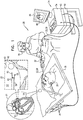
Fig. 1 is a schematic, pictorial illustration of a catheter-based tracking andablation system 20, in accordance with an embodiment of the present invention.System 20 comprises aninsertion tube 60, acardiac catheter 22, anablation catheter 58 and acontrol console 24. In the embodiment described herein,catheter 58 is used for ablation of tissue in aheart 26 in a PV isolation procedure, andcatheter 22 is used for guiding the tip ofcatheter 58 to the desired ablation points. -
Console 24 comprises aprocessor 42, typically a general-purpose computer, with suitable front end and interface circuits for receiving signals fromcatheter 22 and for controlling the other components ofsystem 20 described herein. - A
cardiologist 30inserts catheter 22, usinginsertion tube 60, andcatheter 58 directly through the vascular system of apatient 28. In some embodiments,cardiologist 30inserts catheters cavity 63 separately so as to allow high maneuverability ofcatheter 58 during the ablation procedure. In alternative embodiments,cardiologist 30 may insertcatheters cavity 63 together so as to reduce the amount of punctures in a septal wall ofcavity 63 to a single puncture. The distal end ofcatheter 22 is connected to an expandable distal-end device, in the present example an inflatable balloon denotedcork 52. - A cavity 63 (e.g., left atrium) in
heart 26 comprises pulmonary veins (PVs) 61 and 62.Cardiologist 30 navigatescatheter 22 andcatheter 58 to the vicinity ofPV 62, as shown in aninset 21, using amanipulator 32 near the proximal end of the catheters. The proximal ends ofcatheter 22 andcatheter 58 are connected to interface circuitry (not shown) comprised inprocessor 42. - Referring to an
inset 23, during navigation ofcatheter 22,cork 52 is in a collapsed position so as to allow easy insertion and navigation ofdistal end 40 towardPV 62. - The positions of the distal ends of
catheters cavity 63 are typically measured by applying magnetic position sensing techniques incatheter tracking system 20. In an embodiment,console 24 comprises adriver circuit 34, which drivesmagnetic field generators 36 placed at known positions external topatient 28 lying on table 29, e.g., below the patient's torso. The distal ends of each of the two catheters further comprises one or more magnetic field or impedance sensors, such as advanced current localization (ACL) sensors. The position sensors generate position signals in response to the sensed external magnetic fields, thereby enablingprocessor 42 to map the positions of the distal ends within the heart cavity. The magnetic position sensors are connected to the interface circuitry inprocessor 42.Cardiologist 30 can view the positions of the distal ends on animage 44 ofheart 26 on auser display 46. -
Processor 42 may be programmed in software to carry out the functions that are used by the system, and the processor stores data for the software in amemory 50. The software may be downloaded to console 24 in electronic form, over a network, for example, or it may be provided on non-transitory tangible media, such as optical, magnetic or electronic memory media. Alternatively, some or all of the functions ofprocessor 42 may be carried out by dedicated or programmable digital hardware components. - This method of position sensing is implemented, for example, in the CARTO™ system, produced by Biosense Webster Inc. (Diamond Bar, Calif.) and is described in detail in
U.S. Patents 5,391,199 ,6,690,963 ,6,484,118 ,6,239,724 ,6,618,612 ,6,332,089 ,6,690,963 ,7,729,742 and8,456,182 , inPCT Patent Publication WO 96/05768 U.S. Patent Application Publication 2004/0068178 A1 and inU.S. Patent Application Publication 2015/0141798 A1 , whose disclosures are all incorporated herein by reference. -
Fig. 2 is a schematic side view of adistal end 40 ofcatheter 22, and adistal tip 59 ofcatheter 58, at an ostium of pulmonary vein (PV) 62, in accordance with an embodiment of the present invention. During insertion ofcatheter 22,cork 52 is in a collapsed position. After insertion and navigation to a position of interest (e.g., the ostium of PV 62),cork 52 is inflated to an expanded position, typically using a bio-compatible saline liquid supplied bysystem 20. The figure showscork 52 in its expanded position, after it has been fitted in the ostium ofPV 62 and then inflated. - The diameter of
PV 62 is typically smaller than the width of cavity 63 (e.g., the left atrium) ofheart 26, and therefore the ostium ofPV 62 comprises a funnel-shape. In some embodiments, as inflated,cork 52 assumes a conical shape that fits against the funnel shape of the ostium so that the external surface ofcork 52 is brought into contact with awall 66 in a circumference ofPV 62, as shown inFig. 2 . - In some embodiments,
cork 52 may comprise one or more openings, e.g.,hollow tubes 64, which allow continuous flow of pulmonary blood from the patient's lungs (not shown) toheart 26, without causing formation of thrombus, whilecork 52 is in the expanded position. In yet other embodiments,cork 52 may have a donut shape with a hollow center so as to allow blood flow from the lungs toPV 62 whilecork 52 is in the expanded position.Cavity 63 typically comprises two PVs, e.g., PVs 61 (shown inFig. 1 ) and 62. In alternative embodiments,cork 52 does not comprisetubes 64, and therefore completely blocks the ostium ofPV 62. In this case pulmonary blood may flow from the respective lung tocavity 63, solely throughPV 61. - In an embodiment,
cork 52 comprises aprotrusion 54 located at the perimeter of the wider end ofcork 52. The protrusion is shaped to form anannular guiding trench 56 betweencork 52 andwall 66 ofPV 62.Trench 56 is shaped so thattip 59 ofablation catheter 58 fits into the trench without becoming captured betweenwall 66 andcork 52 during the PV isolation procedure.Cork 52 is further configured to maintain its stability even in an unlikely event oftip 59 being momentarily captured betweenwall 66 andcork 52.Tip 59 typically comprises one or more ablation electrodes for ablating tissue onwall 66. - The example configuration shown in
Fig. 2 is chosen purely for the sake of conceptual clarity. In alternative embodiments, the disclosed techniques may use other shapes of balloons or corks, such as a hexagonal shaped cork or any other suitable shape that enables the formation oftrench 56 having a desirable shape. The trench betweencork 52 andwall 66 is configured to hedgetip 59 from enteringPV 62 or slipping along the wall ofcavity 63, away from the ostium ofPV 62. - In an embodiment, the guiding trench sets the position of
ablation tip 59 at the ostium ofPV 62, thus reducing the probability of accidental ablation to unintended tissue, for example, due to navigation errors of the ablation catheter. For example,cork 52 may blockcatheter 58 from entering, by mistake, intoPV 62 and ablating at a wrong position alongPV 62. In addition, the guiding trench allowscardiologist 30 to perform accurate ablation around the ostium ofPV 62 without unintended deviation ofcatheter 58 intocavity 63. - In other embodiments,
cork 52 is fabricated from materials, such as nylon, PET, urethane or their variants, that are durable against high ablation power and do not conduct ablation power fromtip 59 to undesired locations. By using such materials, the ablation power is applied only to intended ablation locations (e.g., ablation points 68 shown inFig. 3 below). - During a PV isolation procedure, the cardiologist may use imaging techniques, such as fluoroscopy, for accurate navigation of
cork 52 to the ostium ofPV 62. In some embodiments,system 20 is configured to inject into cork 52 a dye saline, such as water-soluble iodine, which is visible to the fluoroscopic imaging system, so as to visualize the shape of the ostium ofPV 62 whilecork 52 is fitted intoPV 62. In other embodiments,cork 52 may comprise a material that is opaque to fluoroscopic radiation (thus, appears dark in a fluoroscopic image) so as to further assist in the visualization of the ostium whilecork 52 is fitted intoPV 62. - The disclosed techniques may employ any device coupled to
catheter 22 that is sufficiently small to enable insertion and navigation of the catheter, and can be extended in the ostium ofPV 62. During insertion of the catheter, the device is in a folded position. After the distal end is positioned at the ostium ofPV 62, the device is unfolded to an extended position, using any suitable unfolding mechanism (e.g., mechanical, electrical, magnetic) controlled byproximal end 32. - For example, the extendable device may comprise a foldable umbrella-shaped mechanism coupled to the distal end. The umbrella may be extended so that its edges extend out of
PV 62, thus forming the annular guiding trench. In some embodiments, the apex of the umbrella is positioned in the ostium, pointing intoPV 62, thus, the trench is formed below the extension and abovewall 66. In alternative embodiments, the apex of the umbrella-shaped distal end points towards the left atrium. The "handle" of the umbrella is positioned in the ostium so that in unfolded position, the extension can be anchored to wall 66 and the trench is formed at the boundary of the extension. -
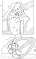
FIG. 3 is a schematic, pictorial illustration ofdistal end 40 in contact withtrench 56 in the circumference ofPV 62, in accordance with an embodiment of the present invention.Cardiac catheter 22 andablation catheter 58 are navigated bycardiologist 30 into cavity 63 (e.g., right atrium). - Referring to an
inset 70,cork 52 is positioned in the ostium of PV 62 (not shown) and inflated using the saline delivered fromproximal end 32 throughtube 60.Hollow tubes 64 allow blood flow throughcork 52, thereby improving hemodynamics. Furthermore,tubes 64 reduce a force required to counter the blood flow so as to maintain the position ofcork 52, yet,tubes 64 may be redundant incase PV 61 is open.Protrusion 54 in the outer perimeter ofcork 52 is configured to formannular guiding trench 56 in the circumference ofcork 52.Trench 56 is shaped so thattip 59 snugly fits in to contactwall 66, as shown inFig. 2 . -
Ablation catheter 58 is navigated to a selectedablation point 68A (one of ablation points 68) so as to perform a first lesion (typically 4 to 6 mm diameter).Tip 59 is further guided alongtrench 56 so as to ablatepoints 68 sequentially by attachingtip 59 to wall 66, at each intended ablation point (e.g., point 68A), and energizingcatheter 58 using RF electrical current. The guiding trench is configured to secure accurate positioning oftip 59 relative to wall 66, thus, preventing accidental ablation at wrong locations (e.g., deeply into PV 62). Furthermore,trench 56 may assist in shortening the navigation time oftip 59 to anablation point 68B, which is the next ablation point in the sequence. The diameter of each lesion point 68 (dictated by RF power and ablation time) and the gaps betweenadjacent points 68 are predefined bycardiologist 30 so as to obtain a complete isolation of the respective PV (e.g., PV 62). -
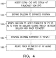
Fig. 4 is a flow chart that schematically illustrates a method for ablatingwall 66 in the circumference of the ostium ofPV 62, in accordance with an embodiment of the present invention. The method begins at aninsertion step 100, in whichcardiologist 30 usesinsertion tube 60 to insertcatheter 22 intocavity 63 whileablation catheter 58 is typically inserted separately.Cardiologist 30 navigatescork 52, which is coupled todistal end 40 ofcatheter 22, into the ostium ofPV 62. At anexpansion step 102,cardiologist 30 inflatescork 52 using saline solution (or any other suitable inflating technique) so as to assume a conical shape ofcork 52 that fits against the funnel shape of the ostium ofPV 62. At atrench formation step 104,cardiologist 30 attachescork 52 to the inner circumference ofPV 62 so as to form anannular guiding trench 56 betweencork 52 andwall 66 ofPV 62. Ascork 52 is properly attached to PV62,cardiologist 30 is free to perform the ablation procedure, rather than being occupied with holdingcatheter 22 against the flow of the pulmonary blood. - At a
positioning step 106, cardiologist positions tip 59 ofablation catheter 58 withintrench 56 attached to wall 66 atablation point 68A. The shape oftrench 56 is designed to guidetip 59 within the trench so as to prevent the tip from slipping away frompoint 68A. At anablation step 108,cardiologist 30 energizesablation catheter 58 using RF electrical current so as to ablatepoint 68A. After concluding the ablation ofpoint 68A,cardiologist 30 may guidetip 59 alongtrench 56 to anadjacent ablation point 68B. The cardiologist then repeats the ablation ofwall 66 atpoint 68B, and repeats the described sequence until concluding the ablation of all points 68. -
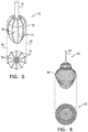
Fig. 5 is a schematic pictorial illustration and a top view of a distal end 72 ofcatheter 22, in accordance with another embodiment of the present invention. Distal end 72 may, for example, replacecork 52 atdistal end 40 ofFig. 2 above. - Distal end 72 comprises an
inflatable balloon 76, which is configured to expand into an expandable position, and arms 74 (also denoted splines), which are configured to form a desired shape ofballoon 76 in the expanded position (as shown in the top view). - During the insertion of
catheter 22,balloon 76 is initially held in a collapsed position. After navigation of the distal end to the ostium of PV 62 (shown inFig. 2 ),balloon 76 is inflated to the expanded position, using the technique described inFig. 2 above. The schematic illustration inFig. 5 showsballoon 76 in its expanded position, after being fitted against the ostium ofPV 62. - In an embodiment,
arms 74 that are coupled toballoon 76, are typically made of bio-compatible materials (e.g., nitinol or pre-shaped materials ofcork 52, such as nylon, PET, or urethane). The arms are configured to shapeballoon 76 in the expanded position as shown in the top view.Arms 74 may be coupled toballoon 76 in a longitude arrangement, as shown inFig. 5 , or in any other suitable arrangement. Aline 78 represents the largest dimension of distal end 72 in the expanded position. This dimension determines the maximal outer perimeter of distal end 72 as shown by dashedlines 80. - In some embodiments, when expanded, distal end 72 assumes a polygon shape as dictated by
arms 74 and shown in the top view. Alternatively, the distal end may assume any other suitable shape that provides the best fit against the ostium ofPV 62. - In other embodiments,
balloon 76 may comprise one or more openings, such ashollow tubes 64, which allow continuous flow of pulmonary blood from the patient's lungs (not shown) toheart 26 as described inFig. 2 above. - In yet other embodiments,
balloon 76 may comprise irrigation tubes (similar totubes 64 shown inFig. 2 ) for the saline that apply irrigation whileballoon 76 still expanded to maintain the required pressure againstPV 62. -
Fig. 6 is a schematic pictorial illustration and a top view of adistal end 82 ofcatheter 22 in accordance with yet another embodiment of the present invention.Distal end 82 may provide the same functionality as distal ends 40 and 72, howeverdistal end 82 comprises a pre-formed spring made of awire 84 rather than an inflatable balloon.Wire 84 is typically fabricated from bio-compatible nitinol or any other suitable material, and its top vertex is comprised incatheter 22. - In some embodiments, during the insertion and navigation phases,
wire 84 may be forced into a sheath (not shown) in a collapsed position. Whendistal end 82 is positioned at the desired location (e.g., in front of ostium of PV 62),wire 84 may be forced out of the sheath so as to expand to its pre-formed profile as shown inFig. 6 . - The external perimeter of the spring may have any desired shape, such as a round shape, as shown in the top view of
Fig. 6 .Position 86 represents the largest dimension ofdistal end 82. This dimension determines the outer perimeter ofdistal end 82 as shown by dashedlines 82. -
Fig. 7 is a schematic pictorial illustration and sectional views B-B and C-C of adistal end 88 ofcatheter 22, in accordance with another embodiment of the present invention.Distal end 88 may, for example, replacecork 52 atdistal end 40 ofFig. 2 above. -
Distal end 88 comprises aninflatable balloon 91, which is substantially similar toballoon 76 shown inFig. 5 and is configured to formtrench 56 as depicted inFig. 2 .Balloon 91 is configured to expand into an expandable position, and arms 89 (similar toarms 74 inFig. 5 ) are configured to form a desired shape ofballoon 91 in the expanded position (e.g., as shown in section C-C).Distal end 88 further compriseselectrodes 90, such as electrophysiological (EP) mapping electrodes, coupled toarms 89 and configured to sense electrical potentials fromPV 62 and generate respective potential gradient signals. In an embodiment,electrodes 90 may be formed on a printed circuit board (PCB) and attached toarms 89. In alternative embodiment,arms 89, includingelectrodes 90, are produced on a flexible PCB. - The gradient signals are transmitted to
processor 42 via wires (not shown) comprised incatheter 22. In other embodiments,electrodes 90 may comprise other types of electrodes such as position sensors, contact sensors (e.g., to monitor whethercatheter 58 is in contact with balloon 91), temperature sensors (e.g., to monitor formation of a lesion), ablation electrodes or any other type of electrode or sensor, suitable for performing a respective medical procedure. -
Distal end 88 further comprises ananchor 92, connected to balloon 91 via aneck section 94.Anchor 92 is also an inflatable balloon. In an inflatable position, the balloon anchorsdistal end 88 to a desirable position alongPV 62 so as to allowcardiologist 30 to perform the ablation procedure, and frees the cardiologist from holdingcatheter 22 against the flow of the pulmonary blood. - During the insertion of
catheter 22,balloon 91 andanchor 92 are initially held in a collapsed position. After navigation of the distal end to the ostium of PV 62 (shown inFig. 2 ),balloon 91 andanchor 92 are inflated to the expanded position, using a technique similar to the technique described inFig. 2 above. The schematic illustration inFig. 7 showsballoon 91 andanchor 92 in their expanded position, after being fitted against the ostium ofPV 62. In alternative embodiments,anchor 92 may be a spring, made of a wire (such as wire 84), as described inFig. 6 above. - In some embodiments, when expanded,
distal end 88 assumes a polygon shape as shown in section C-C. Alternatively, the distal end may assume any other suitable shape to fit against the ostium ofPV 62. - In other embodiments,
balloon 91 may comprise a hollow tube 65 (similar totubes 64 depicted inFig. 2 ), which allows a continuous flow of pulmonary blood from the patient's lungs (not shown) toheart 26, as described inFig. 2 above. In addition,catheter 22 comprises anopening 93, through which the pulmonary blood may flow out oftube 65 on its route toheart 26. In alternative embodiments, opening 93 may be formed as an exit of channels (such astubes 64 shown inFig. 2 ) comprised inballoon 91.Such opening 93 may be located, for example, aboveelectrodes 90, as a single or multiple openings. - In yet other embodiments,
distal end 88 compriseschannels 94 used for inflating (and deflating)balloon 91 andanchor 92. The number of channels may be two, as shown inFig. 7 , or any other suitable number of channels. In an embodiment,balloon 91 andanchor 92 are inflated independently using two separate channels, in whichcase catheter 22 comprises at least twochannels 94. In an alternative embodiment,balloon 91 andanchor 92 may each have, an internal valve (not shown) so that a single channel may be sufficient to inflate both the balloon and anchor. In another embodiment, at least one ofchannels 94 may be used forwiring electrodes 90 toprocessor 42. - In yet another embodiment, at least one of
channels 94 may be used for irrigatingtube 65 for various purposes, such as for flushing out blood residues fromneck 94. - The distal end configurations shown in
Figs. 2 ,5 ,6 and7 are example configurations that are depicted purely for the sake of conceptual clarity. In alternative embodiments, any other suitable distal end configuration can be used. - It will be appreciated that the embodiments described above are cited by way of example, and that the present invention is not limited to what has been particularly shown and described hereinabove. Rather, the scope of the present invention includes both combinations and subcombinations of the various features described hereinabove, as well as variations and modifications thereof which would occur to persons skilled in the art upon reading the foregoing description and which are not disclosed in the prior art.
- Aspects of the invention:
- 1. A method, comprising:
- inserting into a patient body a catheter, which comprises an insertion tube and at least an expandable distal-end device coupled to a distal end of the insertion tube;
- expanding the distal-end device in a blood vessel, thereby forming an annular guiding trench between the distal-end device and a circumference of the blood vessel, the annular trench shaped to receive and guide a distal tip of a medical instrument; and
- guiding the distal tip of the medical instrument in the annular guiding trench formed by the expanded distal-end device of the catheter, so as to approach multiple points on the circumference of the blood vessel.
- 2. The method according to aspect 1, wherein expanding the distal-end device comprises inflating the distal-end device using a saline solution.
- 3. The method according to aspect 2, wherein the saline solution comprises dye visible to X-ray radiation.
- 4. The method according to aspect 1, wherein the distal-end device comprises a material that is opaque to X-ray radiation.
- 5. The method according to aspect 1, wherein the blood vessel comprises a pulmonary vein (PV).
- 6. The method according to aspect 1, wherein expanding the distal-end device comprises inflating the distal-end device so as to form a shape that fits a circumference of an ostium of the blood vessel.
- 7. The method according to aspect 1, wherein the distal-end device comprises at least one opening, which is configured to allow blood flow through the distal-end device when the distal-end device is expanded in the blood vessel.
- 8. The method according to aspect 1, wherein the distal-end device comprises a protrusion, and wherein the annular guiding trench is formed between the protrusion and the circumference of the blood vessel.
- 9. The method according to aspect 1, wherein the distal tip of the medical instrument comprises an ablation electrode, and wherein guiding the distal tip comprises ablating multiple points around the circumference of the blood vessel using the ablation electrode.
- 10. The method according to aspect 1, wherein the distal-end device comprises multiple foldable arms, and wherein expanding the distal-end device comprises unfolding the arms so as to form the annular trench.
- 11. The method according to aspect 1, wherein the distal-end device comprises an expandable spring, and wherein expanding the distal-end device comprises expanding the expandable spring so as to form the annular trench.
- 12. The method according to aspect 1, wherein expanding the distal-end device comprises expanding an anchoring extension in the blood vessel, thereby fixing the distal-end device to the circumference of the blood vessel.
Claims (12)
- A catheter, comprising:an insertion tube for insertion into a patient body; andat least an expandable distal-end device coupled to a distal end of the insertion tube, wherein the expandable device is configured to expand the blood vessel thereby forming an annular guiding trench between the distal-end device and a circumference of the blood vessel, the annular trench shaped to receive and guide a distal tip of a medical instrument.
- The catheter according to claim 1, wherein the distal-end device is configured to inflate using a saline solution.
- The catheter according to claim 2, wherein the saline solution comprises dye visible to X-ray radiation.
- The catheter according to claim 1, wherein the distal-end device comprises a material that is opaque to X-ray radiation.
- The catheter according to claim 1, wherein the blood vessel comprises pulmonary vein (PV).
- The catheter according to claim 1, wherein, at an expanded position, the distal-end device is configured to form a shape that fits a circumference of an ostium of the blood vessel.
- The catheter according to claim 1, wherein the distal-end device comprises at least one opening, which is configured to allow blood flow through the distal-end device when the distal-end device is expanded in the blood vessel.
- The catheter according to claim 1, wherein the distal-end device comprises a protrusion, and wherein the annular guiding trench is formed between the protrusion and the circumference of the blood vessel.
- The catheter according to claim 1, wherein the distal tip of the medical instrument comprises an ablation electrode, which is configured to ablate multiple points around the circumference of the blood vessel using the ablation electrode.
- The catheter according to claim 1, wherein the distal-end device comprises multiple foldable arms, and is configured to unfold the arms so as to form the annular trench.
- The catheter according to claim 1, wherein the distal-end device comprises an expandable spring, which is configured to expand so as to form the annular trench.
- The catheter according to claim 1, wherein the distal-end device comprises an anchoring extension, which is configured to expand in the blood vessel thereby fixing the distal-end device to the circumference of the blood vessel.
Applications Claiming Priority (1)
| Application Number | Priority Date | Filing Date | Title |
|---|---|---|---|
| US15/097,641 US20170296262A1 (en) | 2016-04-13 | 2016-04-13 | Pulmonary-vein cork device with ablation guiding trench |
Publications (1)
| Publication Number | Publication Date |
|---|---|
| EP3231384A1 true EP3231384A1 (en) | 2017-10-18 |
Family
ID=58544865
Family Applications (1)
| Application Number | Title | Priority Date | Filing Date |
|---|---|---|---|
| EP17166327.1A Withdrawn EP3231384A1 (en) | 2016-04-13 | 2017-04-12 | Pulmonary-vein cork device with ablation guiding trench |
Country Status (7)
| Country | Link |
|---|---|
| US (1) | US20170296262A1 (en) |
| EP (1) | EP3231384A1 (en) |
| JP (1) | JP2017189614A (en) |
| CN (1) | CN107280760A (en) |
| AU (1) | AU2017201702A1 (en) |
| CA (1) | CA2962413A1 (en) |
| IL (1) | IL251257A0 (en) |
Families Citing this family (2)
| Publication number | Priority date | Publication date | Assignee | Title |
|---|---|---|---|---|
| US20190175262A1 (en) * | 2017-12-11 | 2019-06-13 | Biosense Webster (Israel) Ltd. | Balloon catheter distal end comprising electrodes and thermocouples |
| CN116942292B (en) * | 2023-09-18 | 2024-01-16 | 迈得诺医疗科技集团有限公司 | Ablation catheter, ablation device and ablation method thereof |
Citations (17)
| Publication number | Priority date | Publication date | Assignee | Title |
|---|---|---|---|---|
| US5391199A (en) | 1993-07-20 | 1995-02-21 | Biosense, Inc. | Apparatus and method for treating cardiac arrhythmias |
| WO1996005768A1 (en) | 1994-08-19 | 1996-02-29 | Biosense, Inc. | Medical diagnosis, treatment and imaging systems |
| US6239724B1 (en) | 1997-12-30 | 2001-05-29 | Remon Medical Technologies, Ltd. | System and method for telemetrically providing intrabody spatial position |
| US6332089B1 (en) | 1996-02-15 | 2001-12-18 | Biosense, Inc. | Medical procedures and apparatus using intrabody probes |
| US6484118B1 (en) | 2000-07-20 | 2002-11-19 | Biosense, Inc. | Electromagnetic position single axis system |
| US6491710B2 (en) | 2000-09-07 | 2002-12-10 | Shutaro Satake | Balloon catheter for pulmonary vein isolation |
| US20030078574A1 (en) * | 2000-04-25 | 2003-04-24 | Hall Jeffrey A. | Ablation catheter, system, and method of use thereof |
| US6572612B2 (en) | 1999-04-05 | 2003-06-03 | Medtronic, Inc. | Ablation catheter and method for isolating a pulmonary vein |
| US6618612B1 (en) | 1996-02-15 | 2003-09-09 | Biosense, Inc. | Independently positionable transducers for location system |
| US6690963B2 (en) | 1995-01-24 | 2004-02-10 | Biosense, Inc. | System for determining the location and orientation of an invasive medical instrument |
| US20040068178A1 (en) | 2002-09-17 | 2004-04-08 | Assaf Govari | High-gradient recursive locating system |
| US7729742B2 (en) | 2001-12-21 | 2010-06-01 | Biosense, Inc. | Wireless position sensor |
| US20100256629A1 (en) * | 2009-04-06 | 2010-10-07 | Voyage Medical, Inc. | Methods and devices for treatment of the ostium |
| US20120271277A1 (en) * | 2011-04-22 | 2012-10-25 | Fischell Innovations Llc | Expandable catheter system for peri-ostial injection and muscle and nerve fiber ablation |
| US8456182B2 (en) | 2008-09-30 | 2013-06-04 | Biosense Webster, Inc. | Current localization tracker |
| WO2014189887A2 (en) * | 2013-05-20 | 2014-11-27 | Mayo Foundation For Medical Education And Research | Devices and methods for ablation of tissue |
| US20150141798A1 (en) | 2013-11-21 | 2015-05-21 | Biosense Webster (Israel) Ltd. | Tracking of catheter from insertion point to heart using impedance measurements |
Family Cites Families (8)
| Publication number | Priority date | Publication date | Assignee | Title |
|---|---|---|---|---|
| US5295958A (en) * | 1991-04-04 | 1994-03-22 | Shturman Cardiology Systems, Inc. | Method and apparatus for in vivo heart valve decalcification |
| EP0850607A1 (en) * | 1996-12-31 | 1998-07-01 | Cordis Corporation | Valve prosthesis for implantation in body channels |
| US5938660A (en) * | 1997-06-27 | 1999-08-17 | Daig Corporation | Process and device for the treatment of atrial arrhythmia |
| US6652515B1 (en) * | 1997-07-08 | 2003-11-25 | Atrionix, Inc. | Tissue ablation device assembly and method for electrically isolating a pulmonary vein ostium from an atrial wall |
| US7008418B2 (en) * | 2002-05-09 | 2006-03-07 | Stereotaxis, Inc. | Magnetically assisted pulmonary vein isolation |
| CN102429721B (en) * | 2010-09-29 | 2015-08-26 | 心诺普医疗技术(北京)有限公司 | A kind of ablation system |
| CN105636538B (en) * | 2013-10-18 | 2019-01-15 | 波士顿科学国际有限公司 | Foley's tube with flexible wire and its correlation technique for using and manufacturing |
| US10568686B2 (en) * | 2013-11-21 | 2020-02-25 | Biosense Webster (Israel) Ltd. | Multi-electrode balloon catheter with circumferential and point electrodes |
-
2016
- 2016-04-13 US US15/097,641 patent/US20170296262A1/en not_active Abandoned
-
2017
- 2017-03-13 AU AU2017201702A patent/AU2017201702A1/en not_active Abandoned
- 2017-03-19 IL IL251257A patent/IL251257A0/en unknown
- 2017-03-28 CA CA2962413A patent/CA2962413A1/en not_active Abandoned
- 2017-04-12 JP JP2017078757A patent/JP2017189614A/en active Pending
- 2017-04-12 EP EP17166327.1A patent/EP3231384A1/en not_active Withdrawn
- 2017-04-13 CN CN201710240179.1A patent/CN107280760A/en active Pending
Patent Citations (17)
| Publication number | Priority date | Publication date | Assignee | Title |
|---|---|---|---|---|
| US5391199A (en) | 1993-07-20 | 1995-02-21 | Biosense, Inc. | Apparatus and method for treating cardiac arrhythmias |
| WO1996005768A1 (en) | 1994-08-19 | 1996-02-29 | Biosense, Inc. | Medical diagnosis, treatment and imaging systems |
| US6690963B2 (en) | 1995-01-24 | 2004-02-10 | Biosense, Inc. | System for determining the location and orientation of an invasive medical instrument |
| US6618612B1 (en) | 1996-02-15 | 2003-09-09 | Biosense, Inc. | Independently positionable transducers for location system |
| US6332089B1 (en) | 1996-02-15 | 2001-12-18 | Biosense, Inc. | Medical procedures and apparatus using intrabody probes |
| US6239724B1 (en) | 1997-12-30 | 2001-05-29 | Remon Medical Technologies, Ltd. | System and method for telemetrically providing intrabody spatial position |
| US6572612B2 (en) | 1999-04-05 | 2003-06-03 | Medtronic, Inc. | Ablation catheter and method for isolating a pulmonary vein |
| US20030078574A1 (en) * | 2000-04-25 | 2003-04-24 | Hall Jeffrey A. | Ablation catheter, system, and method of use thereof |
| US6484118B1 (en) | 2000-07-20 | 2002-11-19 | Biosense, Inc. | Electromagnetic position single axis system |
| US6491710B2 (en) | 2000-09-07 | 2002-12-10 | Shutaro Satake | Balloon catheter for pulmonary vein isolation |
| US7729742B2 (en) | 2001-12-21 | 2010-06-01 | Biosense, Inc. | Wireless position sensor |
| US20040068178A1 (en) | 2002-09-17 | 2004-04-08 | Assaf Govari | High-gradient recursive locating system |
| US8456182B2 (en) | 2008-09-30 | 2013-06-04 | Biosense Webster, Inc. | Current localization tracker |
| US20100256629A1 (en) * | 2009-04-06 | 2010-10-07 | Voyage Medical, Inc. | Methods and devices for treatment of the ostium |
| US20120271277A1 (en) * | 2011-04-22 | 2012-10-25 | Fischell Innovations Llc | Expandable catheter system for peri-ostial injection and muscle and nerve fiber ablation |
| WO2014189887A2 (en) * | 2013-05-20 | 2014-11-27 | Mayo Foundation For Medical Education And Research | Devices and methods for ablation of tissue |
| US20150141798A1 (en) | 2013-11-21 | 2015-05-21 | Biosense Webster (Israel) Ltd. | Tracking of catheter from insertion point to heart using impedance measurements |
Also Published As
| Publication number | Publication date |
|---|---|
| US20170296262A1 (en) | 2017-10-19 |
| AU2017201702A1 (en) | 2017-11-02 |
| CN107280760A (en) | 2017-10-24 |
| JP2017189614A (en) | 2017-10-19 |
| CA2962413A1 (en) | 2017-10-13 |
| IL251257A0 (en) | 2017-06-29 |
Similar Documents
| Publication | Publication Date | Title |
|---|---|---|
| EP3037034B1 (en) | Balloon for ablation around pulmonary veins | |
| JP7046676B2 (en) | Balloon catheter with large area electrodes | |
| AU2018204229B2 (en) | Lasso catheter with tip electrode | |
| EP3574954B1 (en) | Enhanced large-diameter balloon catheter | |
| US20060004352A1 (en) | Apparatus and method for diagnosis and therapy of electrophysiological disease | |
| EP3231384A1 (en) | Pulmonary-vein cork device with ablation guiding trench | |
| JP7297765B2 (en) | Balloon catheter with internal distal tip | |
| JP2020108764A (en) | Balloon catheter with distal end having recessed shape | |
| EP3841998A1 (en) | Lasso catheter with balloon | |
| EP4197473A1 (en) | Basket catheter with cushioning porous sheath cover | |
| KR20220021396A (en) | Balloon probe for irreversible electroporation |
Legal Events
| Date | Code | Title | Description |
|---|---|---|---|
| PUAI | Public reference made under article 153(3) epc to a published international application that has entered the european phase |
Free format text: ORIGINAL CODE: 0009012 |
|
| AK | Designated contracting states |
Kind code of ref document: A1 Designated state(s): AL AT BE BG CH CY CZ DE DK EE ES FI FR GB GR HR HU IE IS IT LI LT LU LV MC MK MT NL NO PL PT RO RS SE SI SK SM TR |
|
| AX | Request for extension of the european patent |
Extension state: BA ME |
|
| 17P | Request for examination filed |
Effective date: 20180418 |
|
| RBV | Designated contracting states (corrected) |
Designated state(s): AL AT BE BG CH CY CZ DE DK EE ES FI FR GB GR HR HU IE IS IT LI LT LU LV MC MK MT NL NO PL PT RO RS SE SI SK SM TR |
|
| STAA | Information on the status of an ep patent application or granted ep patent |
Free format text: STATUS: THE APPLICATION HAS BEEN WITHDRAWN |
|
| 18W | Application withdrawn |
Effective date: 20200601 |