EP3207910A1 - Patient bed control - Google Patents
Patient bed control Download PDFInfo
- Publication number
- EP3207910A1 EP3207910A1 EP17164523.7A EP17164523A EP3207910A1 EP 3207910 A1 EP3207910 A1 EP 3207910A1 EP 17164523 A EP17164523 A EP 17164523A EP 3207910 A1 EP3207910 A1 EP 3207910A1
- Authority
- EP
- European Patent Office
- Prior art keywords
- bed
- patient
- foot
- siderail
- patient bed
- Prior art date
- Legal status (The legal status is an assumption and is not a legal conclusion. Google has not performed a legal analysis and makes no representation as to the accuracy of the status listed.)
- Granted
Links
Images


Classifications
-
- A—HUMAN NECESSITIES
- A61—MEDICAL OR VETERINARY SCIENCE; HYGIENE
- A61G—TRANSPORT, PERSONAL CONVEYANCES, OR ACCOMMODATION SPECIALLY ADAPTED FOR PATIENTS OR DISABLED PERSONS; OPERATING TABLES OR CHAIRS; CHAIRS FOR DENTISTRY; FUNERAL DEVICES
- A61G7/00—Beds specially adapted for nursing; Devices for lifting patients or disabled persons
- A61G7/002—Beds specially adapted for nursing; Devices for lifting patients or disabled persons having adjustable mattress frame
- A61G7/018—Control or drive mechanisms
-
- A—HUMAN NECESSITIES
- A61—MEDICAL OR VETERINARY SCIENCE; HYGIENE
- A61G—TRANSPORT, PERSONAL CONVEYANCES, OR ACCOMMODATION SPECIALLY ADAPTED FOR PATIENTS OR DISABLED PERSONS; OPERATING TABLES OR CHAIRS; CHAIRS FOR DENTISTRY; FUNERAL DEVICES
- A61G12/00—Accommodation for nursing, e.g. in hospitals, not covered by groups A61G1/00 - A61G11/00, e.g. trolleys for transport of medicaments or food; Prescription lists
- A61G12/001—Trolleys for transport of medicaments, food, linen, nursing supplies
-
- A—HUMAN NECESSITIES
- A61—MEDICAL OR VETERINARY SCIENCE; HYGIENE
- A61G—TRANSPORT, PERSONAL CONVEYANCES, OR ACCOMMODATION SPECIALLY ADAPTED FOR PATIENTS OR DISABLED PERSONS; OPERATING TABLES OR CHAIRS; CHAIRS FOR DENTISTRY; FUNERAL DEVICES
- A61G7/00—Beds specially adapted for nursing; Devices for lifting patients or disabled persons
- A61G7/001—Beds specially adapted for nursing; Devices for lifting patients or disabled persons with means for turning-over the patient
-
- A—HUMAN NECESSITIES
- A61—MEDICAL OR VETERINARY SCIENCE; HYGIENE
- A61G—TRANSPORT, PERSONAL CONVEYANCES, OR ACCOMMODATION SPECIALLY ADAPTED FOR PATIENTS OR DISABLED PERSONS; OPERATING TABLES OR CHAIRS; CHAIRS FOR DENTISTRY; FUNERAL DEVICES
- A61G7/00—Beds specially adapted for nursing; Devices for lifting patients or disabled persons
- A61G7/002—Beds specially adapted for nursing; Devices for lifting patients or disabled persons having adjustable mattress frame
- A61G7/005—Beds specially adapted for nursing; Devices for lifting patients or disabled persons having adjustable mattress frame tiltable around transverse horizontal axis, e.g. for Trendelenburg position
-
- A—HUMAN NECESSITIES
- A61—MEDICAL OR VETERINARY SCIENCE; HYGIENE
- A61G—TRANSPORT, PERSONAL CONVEYANCES, OR ACCOMMODATION SPECIALLY ADAPTED FOR PATIENTS OR DISABLED PERSONS; OPERATING TABLES OR CHAIRS; CHAIRS FOR DENTISTRY; FUNERAL DEVICES
- A61G7/00—Beds specially adapted for nursing; Devices for lifting patients or disabled persons
- A61G7/002—Beds specially adapted for nursing; Devices for lifting patients or disabled persons having adjustable mattress frame
- A61G7/012—Beds specially adapted for nursing; Devices for lifting patients or disabled persons having adjustable mattress frame raising or lowering of the whole mattress frame
-
- A—HUMAN NECESSITIES
- A61—MEDICAL OR VETERINARY SCIENCE; HYGIENE
- A61G—TRANSPORT, PERSONAL CONVEYANCES, OR ACCOMMODATION SPECIALLY ADAPTED FOR PATIENTS OR DISABLED PERSONS; OPERATING TABLES OR CHAIRS; CHAIRS FOR DENTISTRY; FUNERAL DEVICES
- A61G7/00—Beds specially adapted for nursing; Devices for lifting patients or disabled persons
- A61G7/002—Beds specially adapted for nursing; Devices for lifting patients or disabled persons having adjustable mattress frame
- A61G7/015—Beds specially adapted for nursing; Devices for lifting patients or disabled persons having adjustable mattress frame divided into different adjustable sections, e.g. for Gatch position
-
- A—HUMAN NECESSITIES
- A61—MEDICAL OR VETERINARY SCIENCE; HYGIENE
- A61G—TRANSPORT, PERSONAL CONVEYANCES, OR ACCOMMODATION SPECIALLY ADAPTED FOR PATIENTS OR DISABLED PERSONS; OPERATING TABLES OR CHAIRS; CHAIRS FOR DENTISTRY; FUNERAL DEVICES
- A61G7/00—Beds specially adapted for nursing; Devices for lifting patients or disabled persons
- A61G7/05—Parts, details or accessories of beds
- A61G7/0503—Holders, support devices for receptacles, e.g. for drainage or urine bags
-
- A—HUMAN NECESSITIES
- A61—MEDICAL OR VETERINARY SCIENCE; HYGIENE
- A61G—TRANSPORT, PERSONAL CONVEYANCES, OR ACCOMMODATION SPECIALLY ADAPTED FOR PATIENTS OR DISABLED PERSONS; OPERATING TABLES OR CHAIRS; CHAIRS FOR DENTISTRY; FUNERAL DEVICES
- A61G7/00—Beds specially adapted for nursing; Devices for lifting patients or disabled persons
- A61G7/05—Parts, details or accessories of beds
- A61G7/0506—Head or foot boards
-
- A—HUMAN NECESSITIES
- A61—MEDICAL OR VETERINARY SCIENCE; HYGIENE
- A61G—TRANSPORT, PERSONAL CONVEYANCES, OR ACCOMMODATION SPECIALLY ADAPTED FOR PATIENTS OR DISABLED PERSONS; OPERATING TABLES OR CHAIRS; CHAIRS FOR DENTISTRY; FUNERAL DEVICES
- A61G7/00—Beds specially adapted for nursing; Devices for lifting patients or disabled persons
- A61G7/05—Parts, details or accessories of beds
- A61G7/0507—Side-rails
- A61G7/0508—Side-rails characterised by a particular connection mechanism
- A61G7/0509—Side-rails characterised by a particular connection mechanism sliding or pivoting downwards
-
- A—HUMAN NECESSITIES
- A61—MEDICAL OR VETERINARY SCIENCE; HYGIENE
- A61G—TRANSPORT, PERSONAL CONVEYANCES, OR ACCOMMODATION SPECIALLY ADAPTED FOR PATIENTS OR DISABLED PERSONS; OPERATING TABLES OR CHAIRS; CHAIRS FOR DENTISTRY; FUNERAL DEVICES
- A61G7/00—Beds specially adapted for nursing; Devices for lifting patients or disabled persons
- A61G7/05—Parts, details or accessories of beds
- A61G7/0507—Side-rails
- A61G7/0508—Side-rails characterised by a particular connection mechanism
- A61G7/051—Side-rails characterised by a particular connection mechanism pivoting sideward
-
- A—HUMAN NECESSITIES
- A61—MEDICAL OR VETERINARY SCIENCE; HYGIENE
- A61G—TRANSPORT, PERSONAL CONVEYANCES, OR ACCOMMODATION SPECIALLY ADAPTED FOR PATIENTS OR DISABLED PERSONS; OPERATING TABLES OR CHAIRS; CHAIRS FOR DENTISTRY; FUNERAL DEVICES
- A61G7/00—Beds specially adapted for nursing; Devices for lifting patients or disabled persons
- A61G7/05—Parts, details or accessories of beds
- A61G7/0507—Side-rails
- A61G7/0512—Side-rails characterised by customised length
- A61G7/0513—Side-rails characterised by customised length covering particular sections of the bed, e.g. one or more partial side-rail sections along the bed
- A61G7/0514—Side-rails characterised by customised length covering particular sections of the bed, e.g. one or more partial side-rail sections along the bed mounted to individual mattress supporting frame sections
-
- A—HUMAN NECESSITIES
- A61—MEDICAL OR VETERINARY SCIENCE; HYGIENE
- A61G—TRANSPORT, PERSONAL CONVEYANCES, OR ACCOMMODATION SPECIALLY ADAPTED FOR PATIENTS OR DISABLED PERSONS; OPERATING TABLES OR CHAIRS; CHAIRS FOR DENTISTRY; FUNERAL DEVICES
- A61G7/00—Beds specially adapted for nursing; Devices for lifting patients or disabled persons
- A61G7/05—Parts, details or accessories of beds
- A61G7/0507—Side-rails
- A61G7/0516—Side-rails with height adjustability
-
- A—HUMAN NECESSITIES
- A61—MEDICAL OR VETERINARY SCIENCE; HYGIENE
- A61G—TRANSPORT, PERSONAL CONVEYANCES, OR ACCOMMODATION SPECIALLY ADAPTED FOR PATIENTS OR DISABLED PERSONS; OPERATING TABLES OR CHAIRS; CHAIRS FOR DENTISTRY; FUNERAL DEVICES
- A61G7/00—Beds specially adapted for nursing; Devices for lifting patients or disabled persons
- A61G7/05—Parts, details or accessories of beds
- A61G7/0507—Side-rails
- A61G7/0524—Side-rails characterised by integrated accessories, e.g. bed control means, nurse call or reading lights
-
- A—HUMAN NECESSITIES
- A61—MEDICAL OR VETERINARY SCIENCE; HYGIENE
- A61G—TRANSPORT, PERSONAL CONVEYANCES, OR ACCOMMODATION SPECIALLY ADAPTED FOR PATIENTS OR DISABLED PERSONS; OPERATING TABLES OR CHAIRS; CHAIRS FOR DENTISTRY; FUNERAL DEVICES
- A61G7/00—Beds specially adapted for nursing; Devices for lifting patients or disabled persons
- A61G7/05—Parts, details or accessories of beds
- A61G7/053—Aids for getting into, or out of, bed, e.g. steps, chairs, cane-like supports
- A61G7/0536—Lifting straps, usually attached to the bed-end and grasped by the patient in order to raise himself into a sitting position
-
- A—HUMAN NECESSITIES
- A61—MEDICAL OR VETERINARY SCIENCE; HYGIENE
- A61G—TRANSPORT, PERSONAL CONVEYANCES, OR ACCOMMODATION SPECIALLY ADAPTED FOR PATIENTS OR DISABLED PERSONS; OPERATING TABLES OR CHAIRS; CHAIRS FOR DENTISTRY; FUNERAL DEVICES
- A61G7/00—Beds specially adapted for nursing; Devices for lifting patients or disabled persons
- A61G7/08—Apparatus for transporting beds
-
- A—HUMAN NECESSITIES
- A61—MEDICAL OR VETERINARY SCIENCE; HYGIENE
- A61G—TRANSPORT, PERSONAL CONVEYANCES, OR ACCOMMODATION SPECIALLY ADAPTED FOR PATIENTS OR DISABLED PERSONS; OPERATING TABLES OR CHAIRS; CHAIRS FOR DENTISTRY; FUNERAL DEVICES
- A61G7/00—Beds specially adapted for nursing; Devices for lifting patients or disabled persons
- A61G7/10—Devices for lifting patients or disabled persons, e.g. special adaptations of hoists thereto
- A61G7/1013—Lifting of patients by
- A61G7/1017—Pivoting arms, e.g. crane type mechanisms
-
- A—HUMAN NECESSITIES
- A61—MEDICAL OR VETERINARY SCIENCE; HYGIENE
- A61G—TRANSPORT, PERSONAL CONVEYANCES, OR ACCOMMODATION SPECIALLY ADAPTED FOR PATIENTS OR DISABLED PERSONS; OPERATING TABLES OR CHAIRS; CHAIRS FOR DENTISTRY; FUNERAL DEVICES
- A61G7/00—Beds specially adapted for nursing; Devices for lifting patients or disabled persons
- A61G7/10—Devices for lifting patients or disabled persons, e.g. special adaptations of hoists thereto
- A61G7/104—Devices carried or supported by
- A61G7/1044—Stationary fixed means, e.g. fixed to a surface or bed
-
- A—HUMAN NECESSITIES
- A61—MEDICAL OR VETERINARY SCIENCE; HYGIENE
- A61G—TRANSPORT, PERSONAL CONVEYANCES, OR ACCOMMODATION SPECIALLY ADAPTED FOR PATIENTS OR DISABLED PERSONS; OPERATING TABLES OR CHAIRS; CHAIRS FOR DENTISTRY; FUNERAL DEVICES
- A61G7/00—Beds specially adapted for nursing; Devices for lifting patients or disabled persons
- A61G7/10—Devices for lifting patients or disabled persons, e.g. special adaptations of hoists thereto
- A61G7/1049—Attachment, suspending or supporting means for patients
- A61G7/1051—Flexible harnesses or slings
-
- G—PHYSICS
- G06—COMPUTING; CALCULATING OR COUNTING
- G06F—ELECTRIC DIGITAL DATA PROCESSING
- G06F3/00—Input arrangements for transferring data to be processed into a form capable of being handled by the computer; Output arrangements for transferring data from processing unit to output unit, e.g. interface arrangements
- G06F3/01—Input arrangements or combined input and output arrangements for interaction between user and computer
- G06F3/048—Interaction techniques based on graphical user interfaces [GUI]
- G06F3/0484—Interaction techniques based on graphical user interfaces [GUI] for the control of specific functions or operations, e.g. selecting or manipulating an object, an image or a displayed text element, setting a parameter value or selecting a range
- G06F3/04842—Selection of displayed objects or displayed text elements
-
- G—PHYSICS
- G08—SIGNALLING
- G08C—TRANSMISSION SYSTEMS FOR MEASURED VALUES, CONTROL OR SIMILAR SIGNALS
- G08C17/00—Arrangements for transmitting signals characterised by the use of a wireless electrical link
- G08C17/02—Arrangements for transmitting signals characterised by the use of a wireless electrical link using a radio link
-
- H—ELECTRICITY
- H02—GENERATION; CONVERSION OR DISTRIBUTION OF ELECTRIC POWER
- H02J—CIRCUIT ARRANGEMENTS OR SYSTEMS FOR SUPPLYING OR DISTRIBUTING ELECTRIC POWER; SYSTEMS FOR STORING ELECTRIC ENERGY
- H02J7/00—Circuit arrangements for charging or depolarising batteries or for supplying loads from batteries
-
- A—HUMAN NECESSITIES
- A61—MEDICAL OR VETERINARY SCIENCE; HYGIENE
- A61G—TRANSPORT, PERSONAL CONVEYANCES, OR ACCOMMODATION SPECIALLY ADAPTED FOR PATIENTS OR DISABLED PERSONS; OPERATING TABLES OR CHAIRS; CHAIRS FOR DENTISTRY; FUNERAL DEVICES
- A61G2203/00—General characteristics of devices
- A61G2203/10—General characteristics of devices characterised by specific control means, e.g. for adjustment or steering
- A61G2203/12—Remote controls
-
- A—HUMAN NECESSITIES
- A61—MEDICAL OR VETERINARY SCIENCE; HYGIENE
- A61G—TRANSPORT, PERSONAL CONVEYANCES, OR ACCOMMODATION SPECIALLY ADAPTED FOR PATIENTS OR DISABLED PERSONS; OPERATING TABLES OR CHAIRS; CHAIRS FOR DENTISTRY; FUNERAL DEVICES
- A61G2203/00—General characteristics of devices
- A61G2203/10—General characteristics of devices characterised by specific control means, e.g. for adjustment or steering
- A61G2203/16—Touchpads
-
- A—HUMAN NECESSITIES
- A61—MEDICAL OR VETERINARY SCIENCE; HYGIENE
- A61G—TRANSPORT, PERSONAL CONVEYANCES, OR ACCOMMODATION SPECIALLY ADAPTED FOR PATIENTS OR DISABLED PERSONS; OPERATING TABLES OR CHAIRS; CHAIRS FOR DENTISTRY; FUNERAL DEVICES
- A61G2203/00—General characteristics of devices
- A61G2203/10—General characteristics of devices characterised by specific control means, e.g. for adjustment or steering
- A61G2203/20—Displays or monitors
-
- A—HUMAN NECESSITIES
- A61—MEDICAL OR VETERINARY SCIENCE; HYGIENE
- A61G—TRANSPORT, PERSONAL CONVEYANCES, OR ACCOMMODATION SPECIALLY ADAPTED FOR PATIENTS OR DISABLED PERSONS; OPERATING TABLES OR CHAIRS; CHAIRS FOR DENTISTRY; FUNERAL DEVICES
- A61G2203/00—General characteristics of devices
- A61G2203/30—General characteristics of devices characterised by sensor means
- A61G2203/44—General characteristics of devices characterised by sensor means for weight
-
- A—HUMAN NECESSITIES
- A61—MEDICAL OR VETERINARY SCIENCE; HYGIENE
- A61G—TRANSPORT, PERSONAL CONVEYANCES, OR ACCOMMODATION SPECIALLY ADAPTED FOR PATIENTS OR DISABLED PERSONS; OPERATING TABLES OR CHAIRS; CHAIRS FOR DENTISTRY; FUNERAL DEVICES
- A61G2203/00—General characteristics of devices
- A61G2203/70—General characteristics of devices with special adaptations, e.g. for safety or comfort
-
- G—PHYSICS
- G06—COMPUTING; CALCULATING OR COUNTING
- G06F—ELECTRIC DIGITAL DATA PROCESSING
- G06F3/00—Input arrangements for transferring data to be processed into a form capable of being handled by the computer; Output arrangements for transferring data from processing unit to output unit, e.g. interface arrangements
- G06F3/01—Input arrangements or combined input and output arrangements for interaction between user and computer
- G06F3/017—Gesture based interaction, e.g. based on a set of recognized hand gestures
-
- G—PHYSICS
- G06—COMPUTING; CALCULATING OR COUNTING
- G06F—ELECTRIC DIGITAL DATA PROCESSING
- G06F3/00—Input arrangements for transferring data to be processed into a form capable of being handled by the computer; Output arrangements for transferring data from processing unit to output unit, e.g. interface arrangements
- G06F3/01—Input arrangements or combined input and output arrangements for interaction between user and computer
- G06F3/048—Interaction techniques based on graphical user interfaces [GUI]
- G06F3/0481—Interaction techniques based on graphical user interfaces [GUI] based on specific properties of the displayed interaction object or a metaphor-based environment, e.g. interaction with desktop elements like windows or icons, or assisted by a cursor's changing behaviour or appearance
- G06F3/0482—Interaction with lists of selectable items, e.g. menus
-
- G—PHYSICS
- G08—SIGNALLING
- G08C—TRANSMISSION SYSTEMS FOR MEASURED VALUES, CONTROL OR SIMILAR SIGNALS
- G08C2201/00—Transmission systems of control signals via wireless link
- G08C2201/20—Binding and programming of remote control devices
-
- G—PHYSICS
- G08—SIGNALLING
- G08C—TRANSMISSION SYSTEMS FOR MEASURED VALUES, CONTROL OR SIMILAR SIGNALS
- G08C2201/00—Transmission systems of control signals via wireless link
- G08C2201/30—User interface
-
- G—PHYSICS
- G08—SIGNALLING
- G08C—TRANSMISSION SYSTEMS FOR MEASURED VALUES, CONTROL OR SIMILAR SIGNALS
- G08C2201/00—Transmission systems of control signals via wireless link
- G08C2201/90—Additional features
- G08C2201/92—Universal remote control
-
- G—PHYSICS
- G08—SIGNALLING
- G08C—TRANSMISSION SYSTEMS FOR MEASURED VALUES, CONTROL OR SIMILAR SIGNALS
- G08C2201/00—Transmission systems of control signals via wireless link
- G08C2201/90—Additional features
- G08C2201/93—Remote control using other portable devices, e.g. mobile phone, PDA, laptop
Definitions
- the present disclosure relates to controllers for patient beds and features of bed frames of patient beds that are typically found in healthcare facilities such as hospitals and nursing homes. More particularly, the present disclosure relates to bed frames having enhanced patient and caregiver interaction such as controlling overall bed functionality, siderail positioning for bed exit, patient repositioning within a bed, transfer of a patient from a bed, and patient therapy.
- An apparatus, system, or method may comprise one or more of the following features alone or in any combination.
- a bed control cart for controlling features of a patient bed may include a wheeled base with foot inputs, a support extending upwardly from the wheeled base, a GUI supported by the support, the GUI displaying hand inputs, and circuitry configured to send wireless signals to control the features of the bed in response to use of each of the foot inputs and hand inputs of the bed control cart.
- the foot inputs may control raising and lowering of an upper frame of the patient bed relative to a base of the patient bed.
- the foot inputs may control tilting of the upper frame of the patient bed between Trendelenburg and reverse Trendelenburg positions.
- the wheeled base may include a set of casters.
- the support of the bed control cart may comprise a pole.
- the GUI may be mounted to an upper end or top of the pole.
- a tray may be mounted to the pole beneath the GUI.
- the hand inputs may control motors that may move mattress support deck sections of the patient bed.
- the hand inputs may control a pneumatic system that may inflate and deflate portions of a mattress of the patient bed.
- the hand inputs may control a mattress therapy function of a mattress of the patient bed.
- the mattress therapy functions may include one or more of the following: a rotation therapy, an alternating pressure therapy, a percussion therapy, a vibration therapy, and a low airloss therapy.
- the hand inputs may control a turn assist function of the patient bed.
- the hand inputs may control a scale system of the bed.
- the circuitry may be configured to receive wireless communications from the patient bed.
- the wireless communications from the patient bed may include information relating to one or more alarms occurring on the patient bed.
- the GUI may, in turn, display information pertaining to the one or more alarms.
- the wireless communications from the patient bed may include information relating to a patient weight as measure by a scale system of the patient bed.
- the wireless communications from the patient bed may include information received by the patient bed from a network of a healthcare facility.
- the hand inputs may be usable to lockout functions of the patient bed from being controlled by user inputs on the patient bed.
- each of the hand controls and foot controls may be able to be locked out from use by user inputs on the patient bed.
- the circuitry may be configured to send wireless signals to control features of at least one other piece of healthcare equipment in response to use of any one or more of the foot inputs and the hand inputs.
- the circuitry of the bed control cart may communicatively pair with bed circuitry of the bed after the bed control cart is brought into a patient room in which the patient bed is located. Furthermore, the circuitry may communicatively pair with bed circuitry of other patient beds in other patient rooms after the bed control cart is brought into respective rooms of the other patient beds.
- At least one user input selection on the hand controls of the GUI may be a prerequisite to the communicative pairing between the circuitry and the bed circuitry.
- at least one user input selection on the foot controls may be a prerequisite to the communicative pairing between the circuitry and the bed circuitry.
- at least one user input selection on at least one user input of the patient bed may be a prerequisite to the communicative pairing between the circuitry and the bed circuitry.
- a patient bed may have foot rails that may be movable by a patient in the bed to an out-of-the-way position to permit the patient to egress from the bed.
- the foot rails may slide relative to a bed frame of the patient bed in a longitudinal direction of the bed.
- a portion of the foot rails may slide relative to a head rail of the patient bed.
- a patient bed may have a head rail with a button that is pressed by a patient in the bed to cause motorized lowering of a foot rail of the patient bed.
- a patient bed may have a foot rail and linkage system that is manually slideable as a unit on a rail of an upper frame of a bed when a patient actuates a release lever of the foot rail.
- a patient bed may have a hub mounted to an upper frame of the patient bed.
- a head rail and a foot rail may each be pivotably coupled to the hub and may be moveable relative to the hub between respective raised and lowered positions.
- a patient bed may have a mattress support deck including a head section having turn assist panels that are cam driven to raised positions.
- a patient bed may have an upper frame and a graphical user interface (GUI) mounted to a top of an arm that has its bottom end coupled to the upper frame.
- GUI graphical user interface
- the arm and GUI may be repositionable as a unit along the upper frame.
- the GUI may comprise a transparent patient control panel mounted to the arm assembly.
- the transparent patient control panel may be operable in a day mode and a night mode. Images on the transparent patient control panel may be controlled via organic light-emitting diode/heads up display (OLED/HUD) technology.
- the arm may have a first arm segment that may extend upwardly from a head deck section and a second arm segment that may extend from an upper end of the first arm over the head deck section.
- a patient bed may have a siderail that moves to a raised position elevated over a central region of a mattress of the patient bed for use as part of a patient lift of the patient bed.
- a patient bed may have physical therapy equipment integrated therein.
- the physical therapy equipment may be integrated into a siderail or footboard of the bed.
- the physical therapy equipment may be attachable to an upper frame of the bed.
- a patient bed may have lift posts at corners of an upper frame and siderails coupled to the lift posts by respective multi-axis joints.
- a mattress for a patient bed may have siderail pads coupled to a main mattress body and the main mattress body may have recesses in an undersurface thereof for storage of the siderail pads.
- a patient bed may have a GUI with a sensor to sense movements of a patient's hand at a distance so that a patient is able to control features of the patient bed without directly touching the GUI.
- a hand avatar may be shown on the GUI when the sensor senses the patient's hand.
- a control module for a patient bed may include a first pendant and a second pendant that may be held in place against the first pendant by a spring loaded clamp.
- the first pendant may have bed controls and the second pendant may have a nurse call button.
- a patient bed may have a port that may be connectable to a handheld electronic device to recharge the handheld electronic device and to download bed control software to the handheld electronic device.
- the handheld electronic device may comprise a phone or a tablet computer, for example.
- the patient bed may include a frame that may have a barrier extending upwardly with respect to a patient support surface and the port may be provided on the barrier.
- the barrier may comprise a siderail.
- user inputs may be coupled to the siderail to control one or more features of the patient bed.
- the siderail may comprise a first siderail and the patient bed may further include a shelf and a second siderail that may be spaced from the first siderail.
- the shelf may be attached to the second siderail, for example.
- the shelf may be pivotable relative to the second siderail to a plurality of positions.
- the patient bed may include a mattress and the shelf may be pivotable relative to the second siderail between a first position overlying the mattress and a second position extending in an opposite direction away from the mattress.
- a control panel housing may be pivotable relative to the siderail between a raised position and a lowered position.
- the control panel housing may move upwardly out of a recess in the siderail when moving from the lowered position to the raised position.
- the patient bed may include a mattress and the control panel housing may carry caregiver controls that may face away from the mattress when the control panel housing is in the raised position and the control -panel housing may have patient controls that may be provided on an edge of the control panel housing.
- a patient bed may have a control module with caregiver controls on one surface and having patient controls on another surface.
- a patient bed may have a control module that may include a generally vertical arm extending upwardly from a base of the patient bed, a GUI mounted to an upper end of the arm, and at least one foot pedal mounted to a lower end of the arm.
- the GUI and at least one foot pedal may be used to send wireless signals to other bed electronics of the patient bed.
- the control module may be repositionable along the base.
- a housing for the GUI may have patient controls on a back wall thereof.
- a siderail may have a trough along its upper edge for receipt of patient care lines.
- a patient bed may have a GUI in a siderail that may deploy automatically out of a cavity in a siderail to a use position in response to a brake pedal of the patient bed being moved to a brake position to brake casters of the patient bed.
- the GUI may be moved automatically back into the cavity in response to the brake pedal being moved to another position other than the brake position.
- a patient bed may have a sensor to sense presence of a user's foot in a designated region and movement of the user's foot into the designated region may cause a preselected feature of the patient bed to operate.
- the patient bed may further have a control panel that may be used to select the preselected feature from among a plurality of bed features to bed operated subsequently by movement of the user's foot into the designated region.
- the patient bed may have a frame that may include a base frame and an upper frame supported above the base frame.
- the control panel may be coupled to the upper frame.
- the designated region may be defined by a light curtain beneath the base frame. Interruption of the light curtain by the user's foot may result in operation of the preselected feature.
- the patient bed may have a mattress and the preselected feature may include a turn assist function of the mattress.
- a patient bed may have a siderail with an integrated line clip.
- a patient bed may have a drainage bag holder including a bar and a sensor to sense when a drainage bag is coupled to the bar.
- the drainage bag holder may be located at a foot end of an upper frame of the bed.
- the drainage bag holder may include a substantially vertically oriented plate and the bar may be pivotably coupled to the substantially vertically oriented plate.
- pivot tabs may extend from the plate and the bar may be pivotably coupled to the pivot tabs.
- the drainage bag holder may further include a pair of cosmetic trim pieces that may be situated on the substantially vertically oriented plate between respective pairs of pivot tabs.
- the senor may include a limit switch that may be received in a hole formed in the substantially vertically oriented plate.
- the limit switch may have a lever that is contacted and moved to a closed position by an arm that may extend from a shelf of the bar when the drainage bag is attached to the bar.
- a patient bed may have a footboard that flips up to serve as an overbed table.
- a patient bed may have a footboard that flips down to serve as a foot deck extension for the patient bed.
- a patient bed may have a footboard with telescopic segments that may move between extended and retracted positions.
- a patient bed may have a footboard with an integrated television unit.
- the television unit may store downwardly in a footboard body and may raise upwardly out of the footboard body for viewing.
- a patient bed may project a lighted bed exit zone image onto a floor at a side of the bed.
- the lighted bed exit zone image may include text that may indicate a status of a position of an upper frame of the bed relative to a lower frame of the bed.
- the text may include the words "BED NOT LOW” if the upper frame of the bed is not in a lowered position relative to the lower frame.
- the words "EXIT ZONE” also may appear in the lighted bed exit zone image in some embodiments.
- the lighted bed exit zone image may be generally semicircular in overall shape but all other shapes are within the scope of this disclosure.
- a patient bed may light up an icon on a footboard to notify a patient not to get out of the bed.
- a patient bed may light up icons on a footboard to indicate a status of monitored features of the patient bed.
- the icons may be illuminated green to indicate a satisfactory status of an associated monitored bed feature.
- the icons may be illuminated a color other than green to indicate an unsatisfactory status of the associated monitored condition.
- the icons may be unlit if the associated feature of the bed is not being monitored.
- the icons may comprise translucent portions of a wall of the footboard.
- the patient bed may further include lights that may be situated behind the translucent portions.
- a patient bed may project icons onto a floor near a foot end of the bed and may project a message onto the floor near a side of the bed.
- each of the icons may indicate a status of a respective monitored feature of the bed.
- the message may advise the patient to call a nurse if the patient desires to get out of the bed.
- the icons may be illuminated green to indicate a satisfactory status of an associated monitored feature.
- the icons may be illuminated a color other than green to indicate an unsatisfactory status of the associated monitored feature.
- each icon is not projected onto the floor if the associated feature of the bed is not being monitored.
- a patient bed may have a footboard with a foot warmer.
- a patient bed may have a camera that automatically takes a picture of a patient on the bed when a weight scale reading is taken.
- the weight reading and the picture may be transmitted from the bed to a remote computer.
- a patient bed may have sensors in surfaces of the bed to sense whether the bed is clean or dirty and may have a display to indicate whether the bed is clean or dirty.
- the surfaces of the bed having at least one of the sensors may include a surface of a siderail of the bed. Alternatively or additionally, the surfaces of the bed having at least one of the sensors may include a surface of an endboard of the bed. In some embodiments, the sensors may detect cleaning agents.
- the patient bed may include a lighted sign that may display a message to indicate whether the bed is clean or dirty. The lighted sign may be coupled to a footboard of the bed, for example. The lighted sign may face away from a mattress of the bed. In response to the sensors indicating that the bed is clean and in response to a weigh scale system indicating a patient is not on the bed, the weigh scale system may be automatically zeroed.
- a patient bed may have nozzles through which a disinfectant mist is sprayed onto surfaces of the bed.
- a patient bed may have integrated UV lights to disinfect surfaces of the bed.
- a patient bed may have an egress seat that may deploy out of an upper frame of the bed for a patient to sit during egress.
- a wheeled chair may dock with the egress seat.
- the wheeled chair may have arms that may be received by channels at the sides of the egress seat when the wheeled chair is docked to the egress seat.
- the egress seat may deploy laterally outwardly from the upper frame in a direction substantially perpendicular to a long dimension of the bed.
- the arms may be configured so that the patient stands between the arms when moving from the egress seat onto a set of the wheeled chair.
- the arms and channels may be substantially at the same elevation and oriented horizontally when an upper frame of the bed is in a lowered position relative to base of the bed.
- a patient bed may have a frame, a siderail that may be coupled to the frame and that may be moveable relative to the frame between a raised position and a lowered position, and an egress handle that may be movable upwardly out of a top opening of the siderail from a storage position to a use position.
- An upper end region of the egress handle may be gripped by a patient during egress from the bed when the siderail is in the lowered position.
- the siderail may comprise a foot rail and the patient bed may further include a head rail that may be coupled to the frame.
- the siderail may include a siderail body that may have a channel and the egress handle may be received in the channel for movement between the storage and use positions.
- the channel may be inclined such that the egress handle may move within the channel along a path that is neither horizontal nor vertical.
- the egress handle may have a recess that may facilitate the patient gripping the upper end region.
- the patient bed may further include a lock to lock the egress handle in the raised position relative to the siderail.
- the patient bed may further have a second egress handle that may be movable relative to the siderail.
- the second egress handle may be extendable horizontally from a head end of a body of the siderail to provide a grip handle for use by a patient during egress from the bed when the siderail is in the raised position.
- a patient bed may include a frame and a siderail that may be coupled to the frame.
- the siderail may have a main body and a shelf may be coupled to the main body.
- the shelf may have a use position extending from the siderail in a cantilevered manner.
- the patient bed may also have an inductive charger that may be coupled to the shelf.
- the inductive charger may be operable to inductively recharge electrical devices placed upon the shelf.
- the shelf may be movable relative to the siderail between the use position and a storage position.
- the inductive charger may be situated beneath an upper surface of the shelf.
- the inductive charger may be situated in an interior region of the shelf.
- the inductive charger may be supported by an upper surface of the shelf.
- the inductive charger may be embedded in a recess in the upper surface of the shelf.
- an upper surface of the inductive charger and the upper surface of a remainder of shelf around the recess may be substantially coplanar.
- the electrical devices that the inductive charger may be operable to inductively recharge include one or more of the following: a smart phone, a tablet computer, and a laptop computer.
- a patient bed may include a frame that may have an upper frame and generally vertical lift legs at corners of the upper frame. At least one caster shroud may have at least one aperture through which a corresponding one of the lift legs may extend.
- the lift legs may extend and retract such that the at least one shroud and the upper frame may move upwardly and downwardly relative to the lift legs.
- the patient bed may have at least one caster beneath the at least one caster shroud and when the lift legs are fully retracted, the upper frame may be in a lowered position having the at least one caster engaging a floor beneath the at least one caster shroud.
- the at least one caster When the lift legs are extended from the fully retracted position, the at least one caster may be moved upwardly out of contact with the floor.
- the at least one caster shroud may be coupled to the upper frame to move upwardly and downwardly therewith as the lift legs extend and retract.
- a patient bed may include a frame, a footboard that may be coupled to the frame, an arm that may extend from the footboard over a patient support surface of the frame, and a control unit that may be mounted to an end of the arm.
- the control unit may include a graphical user interface (GUI) and a sensor to sense movements of a patient's hand at a distance so that a patient may be able to control features of the patient bed without directly touching the GUI.
- GUI graphical user interface
- a hand avatar may be shown on the GUI when the sensor senses the patient's hand.
- the control unit may include at least one grip handle arranged to be grabbed by a patient during egress from the patient bed.
- the at least one grip handle may be located below the GUI.
- the patient bed may further include caregiver controls that may be located on a side of the control unit.
- a patient bed may include a frame that may have a first end and a second end.
- the first end of the frame may include a laterally extending rail.
- a collar may be mounted to the rail and may be repositionable along the rail.
- An oxygen tank holder may be attached to the collar to move with the collar along the rail.
- the oxygen tank holder may include a cylindrical wall.
- the oxygen tank holder may be offset from the collar by an arm.
- the rail may be arched in some embodiments.
- the rail may be generally triangular in cross section and the collar may be shaped complementary to the rail
- the patient bed may further include a patient helper that may have a first arm portion that may extend upwardly from the collar and a second arm portion that may extend in a generally horizontal cantilevered manner from an upper end of the first arm portion over a patient support surface of the frame.
- the patient helper may further include a third arm portion that may telescopically extend and retract relative to the second arm portion.
- the patient helper may include a grab bar that may hang at a lower end of a tether that may extend downwardly from an end of the third arm portion.
- the grab bar may be generally triangular in shape.
- the grab bar may include a tubular portion that may have a pair of hand grip areas.
- the grab bar may include a patient control housing with patient controls that may be used to control one or more functions of the patient bed.
- a patient bed may include a patient position monitoring system that may have a first mode of operation in which an alarm may be generated at the patient bed and an alert message may be sent to a nurse call system in response to a threshold amount of movement of a patient relative to the patient bed.
- the patient position monitoring system may have a second mode of operation in which an alert may be sent to the nurse call system but no alarm may be generated at the patient bed in response to the threshold amount of movement of the patient relative to the patient bed.
- the patient position monitoring system may have a third mode of operation in which an alarm may be generated at the patient bed and an alert message may be sent to a nurse call system in response the patient moving by a lesser amount than the threshold amount relative to the patient bed.
- the lesser amount may correspond, for example, to the patient sitting up in the patient bed or moving to the edge of the patient bed.
- the threshold amount of the first and second modes may correspond to the patient being out of the bed, if desired.
- the patient bed may further include a patient exit assist input that, when selected, may result in at least one siderail of the patient bed moving automatically from a raised position to a lowered position.
- selection of the patient exist assist input may cause a head section of a mattress support deck of the patient bed to raise to a predetermined position if the head section is lower than the predetermined position when the patient exit assist input is selected.
- selection of the patient exit assist input may cause a thigh and foot section of a mattress support deck of the patient bed to lower if they are raised when the patient exist assist input is selected.
- selection of the patient exit assist input may cause at least one bladder of an air mattress to be inflated to a target pressure if the bladder has a lower pressure than the target pressure when the patient exit assist input is selected.
- the at least one bladder may include or be included in a seat section of the air mattress.
- an exit assist alert may be sent from the patient bed to a nurse call system in response to the selection of the patient exit assist input.
- a night light of the patient bed may be illuminated brighter in response to the selection of the patient exit assist input.
- the patient exit assist input may include a button that may be selected by pressing the button.
- a system may include a patient bed that may include a scale system and a radio frequency identification (RFID) tag reader.
- the system may also have one or more RFID tags that may be programmable with equipment weight data.
- the RFID tags may be attachable to respective equipment to be added to the patient bed.
- the RFID tag reader may read the RFID tags of the equipment added to the bed.
- the scale system may recalculate a tare weight to account for a weight of the equipment added to the bed.
- a mattress control box may comprises the equipment added to the bed although the RFID tags may be used in connection with any desired equipment that may be added to a bed.
- each of the RFID tags may include a connector, such as a universal serial bus (USB) connector.
- USB universal serial bus
- Each of the RFID tags may include a cover that may be removable from the remainder of the respective RFID tag to expose the USB connector.
- The may further include a computer and the USB connector of the RFID tag may be coupled to a USB port of the computer to be programmed by the computer with the equipment weight data of respective equipment.
- the USB connector of the RFID tag may be coupled to a USB port of the computer to have a battery of the RFID tag charged.
- a patient bed may include a siderail that may have a urinal dock.
- the urinal dock may include a recess for a handle of a urinal.
- the siderail may include a coupling bar that may extend across the recess to retain the handle of the urinal in the recess when the urinal is docked to the siderail.
- the recess may be open at a top edge of the siderail.
- the siderail may further include a grab handle that may be below the recess.
- the siderail may include a channel that may be configured to receive a portion of a control pendant alongside the recess.
- the channel may be complementary in shape to a shaped edge of the control pendant.
- a top edge of the siderail may include a line manager.
- the line manager may comprise a notch that may be situated alongside an opening to the recess that may be located at the top edge of the siderail.
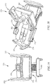
- a patient bed 10 has four siderails including a pair of foot rails 12 that each overlaps a respective head rail 14 of a pair of head rails 14. As a head section 16 of the bed is raised, each head rail 14 pivots about a respective circular hub 18 that does not pivot. Hub 18 includes a patient control panel 20.
- Each foot rail 12 is manually movable by a patient from a first position, shown in Fig. 1 , to a second position, shown for example in Fig. 4 . In the first position, the foot rail 12 blocks the patient from egressing from bed 10 as shown in Fig. 2 . When the foot rail 12 is in the second position, the patient is able to egress from the bed as shown in Fig. 4 .
- a foot end 22 of the foot rail 12 translates along an upper frame 24 of the bed 10 and a head end 26 of the foot rail 12 translates along the associated head rail 14.
- the head rails 14 each have a track or groove 28 that receives an antifriction element (not shown), such as a roller or glide pad, that is mounted to a sidewall of the foot rail 12 near the head end 26.
- an antifriction element such as a roller or glide pad
- Another antifriction element (not shown) provides the interface between the foot end 24 of the foot rail 12 and the upper frame 24 of bed.
- the upper frame also has a track or groove to receive the antifriction element.
- the foot rail 12 of Figs. 1-4 works similar to the manner in which a sliding door of a minivan works. Movement of the foot rails 12 of bed 10 between the first and second positions is easily accomplished by the patient.
- a post extending from each foot rail 12 enters into an interior region of the associated head rail 14 through a slot and attaches to a gas cylinder damper situated in the interior region of the head rail 14.
- the gas cylinder damper holds the foot rail 12 in any position between the first and second positions relative to the head rail 14.
- bed 10 has a caregiver control pod 30 mounted to the foot rail 12.
- the pod 30 is a wireless module communicates wirelessly with bed control circuitry carried by the upper frame of the bed. Thus, there are no electrical wires that need to be routed through the foot rails 12 of bed 10.
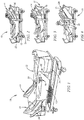
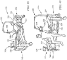
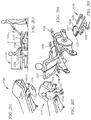
- a patient bed 50 has four siderails including a pair of foot rails 52 and a pair of head rails 54.
- the foot rails 52 partially overlap a respective head rail 54 when the foot rails are in an extended position as shown in Figs. 5 and 6 .
- the foot rails 52 substantially overlap the head rails when the foot rails are in a retracted position as shown in Fig. 7 .
- a foot end 56 of each foot rail has a downwardly extending arm 58 that carries an anti-friction element 60, such as a roller of glide pad, that is received in a slot 62 formed in a frame member 64 of an upper frame 66 of the bed 50 as shown in Fig. 5 .
- a head end 68 of each foot rail 52 includes a slider 70 that couples to an elongated middle tube 72 of the associated head rail 54.
- the slider 70 is near a foot end 74 of the associated head rail 54.
- the slider 72 is near a head end 76 of the respective head rail 54.
- the foot rails 52 and the head rails 54 each having an upper tube 71, a middle tube 72, and a lower tube 73.
- each of the tubes 71, 72, 73 of the foot rails 52 and head rails 54 are oriented substantially horizontally.
- End caps 79 are provided at the foot end 56 of foot rails 52 and both ends of the head rails 54. The end caps 79 interconnect the ends or the respective tubes 71, 72, 73.
- the slider 70 serves as the end cap at the head ends 68 of the foot rails 52.
- each slider 70 is configured to accommodate the pivoting movement of the head rails 54 as the head section 78 is raised and lowered.
- each slider 70 includes an outer piece fixed to the tubes 71, 72, 73 of the associated foot rail 52 and an inner piece coupled to the middle tube 72 of the associated head rail 54.
- the inner piece of each of the sliders 70 is rotatable relative to the outer piece and the inner piece of each slider 70 slides along the middle tube 72 of the associated head rail 54 as the foot rail 52 is extended and retracted relative to the respective head rail.
- a patient bed 80 has a button 82 on a head rail 84 that is pressed by a patient to initiate motorized lowering of an associated foot rail 86.
- Both head rails 84 of bed 80 have buttons 82 even though only one button 80 can be seen in Fig. 8.
- Fig. 9 shows an enlarged view of one of the buttons 82 and there is an indicia or icon 88 on button 82 that depicts the foot rail lowered and a patient swinging one leg out of bed over the lowered foot rail.
- pressing button 82 also causes motorized raising of a head section 90 of bed 80.
- Head section 90 raises while button 82 is pressed and stops raising when button 82 is released. Additionally, in some embodiments, pressing button 82 also causes thigh and foot sections of bed 80 to flatten if they were raised to provide a knee break. The thigh and foot sections are unnumbered in Figs. 8 and 10 but are well-known the art of patient beds. Further additionally, in some embodiments, a signal is sent from bed 80 to a nurse call system when either of buttons 82 is pressed in order to alert one or more nurses that the patient is preparing to exit bed 80. In some embodiments, a night light of bed 80 is turned on or is illuminated more brightly in response to either of buttons 82 being pressed as shown in Fig. 10 .
- a caregiver control panel 92 of bed 80 includes user inputs that caregivers can use to lockout or disable buttons 82 from being usable by a patient to lower the foot rails 86 (and to disable the other bed movements and bed signal to a nurse call system that occur when button 82 is pressed).
- the user inputs also can be used to enable the functionality of button 82 after it has been disabled. If the buttons 82 are disabled and a patient presses either of buttons 82, a nurse call signal is sent from the bed to a nurse call system so that caregivers are made aware of the patient's desire to exit from bed 80 and can go to the patient's room to assist the patient.
- foot rails 86 include normal latch releases for caregivers to manually lower siderails in a manner well known in the art. During motorized lowering of the foot rails 86 in response to presses of buttons 82, the motor speed is slow such that the lowering of the foot rails 86 by the patient occurs slowly. During normal latch release by a caregiver, the foot rails 86 can be lowered much more quickly.
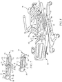
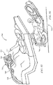
- a patient bed 100 has a pair of foot rails 102 that each includes a lever 104 that is accessible in a hand hole 106 and that is used by a patient to release the associated foot rail 102 for translational movement along a frame 108 of the bed 100.
- a grip handle 110 over the hand hole 106 has a stepped bottom surface to provide grip areas 112 separated by steps 114. The patient holds onto each respective grip area 112 while moving the foot rail 102 in increments toward a head end 116 of the bed 100. After the patient moves one of the foot rails 102 from an egress blocking position, as shown in Fig. 11 , to an out-of-the-way position, as shown in Fig. 12 , the patient is able to egress from bed 100 at its side.
- the bed frame 108 includes a longitudinally extending rail 118 that is supported by a pair of laterally extending tubes 120 at a distance from a longitudinally extending upper frame member 122 of bed 100.
- a slider 124 is mounted on rail 118 and a pair of links 126 interconnects the slider 124 and the associated foot rail 102. When slider 124 is located near a foot end 128 of rail 118, it is locked in place. When the patient pulls lever 104, slider 124 is unlocked from the rail 124 to permit the patient to manually move the associated foot rail 102, links 126, and slider 124 as a unit along rail 118 toward the head end of bed 116.
- slider 118 When slider 118 reaches a head end 130 of rail 118, it once again locks in place on rail 118.
- a second release lever 132 is provided on each foot rail 102 for use by the patient to unlock slider 118 from its locked condition adjacent head end 130 of rail 118 so that the foot rail 102, links 126 and slider 124 can be moved back to their original position blocking patient egress from the bed 100.
- bed 100 Other features of bed 100 include a cup holder 134 that stores flush in one of a pair of head rails 136, as shown in Fig. 11 , and a pendulum cup holder 138 that is coupled to the other of the pair of head rails 136, as shown in Fig. 12 .
- the pendulum cup holder pivots relative to the head rail 136 due to the force of gravity in order to maintain a drink cup in an upright position as the head section of bed 100 is raised and lowered.
- a night light of bed 100 is turned on or made to illuminate more brightly in response to lever 104 being actuated to unlock an associated foot rail 102 for movement toward the head end 116 of bed 100.
- Each foot rail 102 and each head rail 136 includes a release handle 140 that is used by a caregiver to manually unlock the associated foot rail 102 or head rail 136 for manual lowering.
- a patient bed 142 has four side rails including a pair of foot rails 144 and a pair of head rails 146.
- Each foot rail 144 is coupled to a circular hub 148 and is able to be manually rotated by a patient relative to the hub 148 from a horizontal lowered position, shown in Fig. 14 , to a vertical raised position to permit patient egress from the bed 142 as shown in Fig. 13 .
- Each head rail 146 is also coupled to a respective hub 148 and is able to rotate relative to the hub 148 between respective raised and lowered positions. The head rails 146 rotate relative to hub 148 when a head section 150 of bed 142 is raise and lowered.
- the foot rails 144 and the head rails 146 on each side of bed 142 rotate about a common axis 152 of hub 148.
- a stop within hub 148 prevents the foot rails 144 from rotating below their horizontal lowered positions.
- Hubs 148 are each coupled to one end of an L-shaped arm 154 that has its other end coupled to a frame member 156 of an upper frame 158 of bed 142.
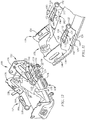
- a mattress support deck 160 has left and right turn assist panels 162, 164 coupled to a head section 166 of the deck 160.
- Panels 162, 164 are each rectangular in the illustrative example.
- Head section 166 has a pair of rectangular holes 168 formed therein, only one of which can be seen in Fig. 15 .
- the panels 162, 164 are pivotably coupled to end walls 170 that define the head end and foot ends of each hole 168.
- the pivotable coupling of the panels 162, 164 to walls 170 is adjacent to the corner regions of holes 168 toward the central region of head section 166.
- a cam 172 is mounted to a shaft 174 that extends longitudinally between walls 170 of hole 168.
- the shaft 174 is situated about midway between the corner regions of hole 168 and is a parallel with the long sides of the rectangular hole 168.
- Cam 172 is mounted on shaft 174 about midway between the end walls 170 of hole 168. Each cam 172 engages a bottom surface of the respective panel 162, 164.
- each shaft 174 by a respective motor (not shown) in a first direction causes the associated cam 172 to wipe against the bottom surface of the respective panel 162, 164 and lift the panel upwardly as shown in Fig. 15 for panel 162.
- Rotation of each shaft 174 by the respective motor in a second direction, opposite to the first direction permits the associated panel 162, 164 to lower back down onto head section 166.
- shafts 174 are rotated less than a full revolution, such as on the order of about 90°, while lifting and lowering panels 162, 164. Movement of panels 162, 164 upwardly provides a bed 176 with turn assist functionality as shown in Fig. 16 .
- a mattress 178 of bed 176 has a portion lifted upwardly by the articulated left turn assist panel 162 in the illustrative example.
- mattress 178 is a foam mattress.
- a portion 180 of another patient bed has head and foot rails 182, 184 on one side of a mattress 186 remaining in horizontal alignment even though a head section 188 of a mattress is raised.
- a head rail 182 on an opposite side of the mattress 186 includes a head rail portion 190 that pivots upwardly to provide additional egress barrier coverage in the region of the raised head section 188 of mattress 186.
- the head rails 182 each have a push button 192 near a head end 194 of the head rail 182.
- Button 192 is pressed to release portion 190 for upward manual movement.
- portion 190 is locked in place in its raised position.
- a patient control panel 196 extends laterally from a foot end 198 of the head rail 182 and a set of caregiver controls 197 are provided on an inclined surface 199 near the foot end 198 of each head rail 182 as also shown in Fig. 18 .
- buttons 192 are omitted and the head rail portion 190 pivots upwardly automatically in response to the head section 188 of the mattress 186 being raised. Accordingly, portion 190 is moved by a motor in the Fig. 19 example.
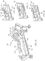
- a patient bed 200 has a siderail, illustratively a foot rail 202, in a lowered position and has an extendable egress handle 204 raised upwardly within an inclined channel 206 formed in a foot rail body 208 to provide a grip handle for use by a patient egressing from the bed 200 when the foot rail 202 is in the lowered position.
- the incline of the channel 206 is such that the egress handle 204 moves within the channel 206 along a path that is neither horizontal nor vertical.
- Channel 206 terminates at an opening 209 located at the top of body 208 and handle 204 moves upwardly out of opening 209 when being raised to a use position. As shown in Fig.
- foot rail 202 has a second egress handle 210 that is extendable horizontally from a head end 212 of the foot rail body 208 to provide a grip handle for use by a patient egressing from the bed when the foot rail 202 is in a raised position.
- Fig. 22 shows that the extendable egress handle 204 has a recess 214 that facilitates the patient gripping the upper end region of handle 204.
- a lock 203 is provided in handle 204 to lock handle 204 in the raised position relative to body 208 of siderail as shown in Fig. 21 .
- Lock 203 includes a linkage 205 and a pair of pins 207 that extend outwardly from sides of handle 204 and that are received in apertures (not shown), such holes or pockets, formed in walls of body 208 that define the sides of channel 206.
- a paddle 215 in recess 214 is moved by the patient to actuate linkage 205 thereby to retract pins 207 from the apertures to permit handle 202 to be moved from the raised, use position back to a lowered, storage position.
- a similar type of lock is provided in handle 210 in some embodiments.
- illustrative lock 203 Other suitable locks that may be used in lieu of illustrative lock 203 include a wrap spring clutch mechanism (e.g., a MECHLOK® device available from Porter Systems, Inc. of Novi, Michigan) having one end attached to handle 204 and the other attached to body 208 of siderail 202, a locking gas spring having one end attached to handle 204 and the other end attached to body 208 of siderail, a ratchet type mechanism, and a jack screw device, just to name a few.
- a wrap spring clutch mechanism e.g., a MECHLOK® device available from Porter Systems, Inc. of Novi, Michigan
- a patient bed 220 has head and foot rails 222, 224 that each comprises a curved flexible panel 226.
- a pair of curved guide posts 228 is each located between respective head and foot rails 222, 224 to provide guide channels for a head end of the respective foot rail 224 and a foot end of the respective head rail 222.
- a control pendant 230 is extendable out of a channel 232 formed in each post 228.
- Pendant 230 has patient controls on one side and caregiver controls on the other side.
- a head board 234 of bed 220 has guide channels for head ends of the head rails 222 and a foot board 236 has guide channels for foot ends of the foot rails 224.
- head rails 222 between raised and lowered positions is guided by the guide channels of the head board 234 and guide posts 228.
- foot rails 224 between raised and lowered positions is guided by the guide channels of the foot board 236 and guide posts 228.
- the guide posts are able to be folded downwardly to a storage position.
- a patient bed 240 has a head rail 242 with a foot end portion 244 pivoted to a head end portion 246 for movement about a generally vertical pivot axis 248.
- the foot end portion 244 of the head rail 242 pivots by about 90° relative to the head end portion 246 so that the foot rail portion 244 extends away from an associated mattress 250 to provide a grip handle for patient egress as shown in Fig. 28 .
- a patient bed 260 has four siderails 262 that each include an upper section 264 that moves relative to a lower section 266 from a raised position to a lowered position such that when the upper section 264 is in the lowered position, the siderail is compact and can be rotated outwardly away from a mattress 268 of bed 260 and then slid underneath the mattress 268 for storage in an orientation substantially parallel with the mattress 268.
- Fig. 30 shows one of the foot rails of the siderails 262 in the storage position.
- Fig. 31 shows the foot rail 262 pulled out from under the mattress and rotated slightly upwardly.
- Fig. 32 shows the foot rail 262 oriented vertically with the upper section 264 raised relative to the lowered section 266.
- a patient bed 270 has expandable width siderails 272 and a repositionable caregiver graphical user interface (GUI) 274.
- GUI 274 is shown at a foot end 276 of the bed adjacent a central region of a footboard 278 in Figs. 33 and 34 .
- the GUI 274 is moved to a corner region of an upper frame 280 of the bed 270 in Fig. 35 .
- a fold out shelf or overbed table 282 in a use position relative to one of the siderails 272 is also shown in Fig. 35 .
- Shelf 282 extends from the siderail in a cantilevered manner when in the use position. Shelf 282 is movable relative to the siderail from the use position to a storage position folded against the siderail 272.
- a patient's feet are located against footboard 278 and, according to this disclosure, the footboard 278 includes a foot massager (not shown).
- an inductive charger is carried by shelf 282.
- the inductive charger is situated beneath the upper surface of shelf 282, such as being situated in an interior region of shelf 282.
- the inductive charger is supported by the upper surface of shelf 282.
- an inductive charger is embedded in a recess in the upper surface of shelf 282 such that an upper surface of the inductive charger and an upper surface of the remainder of shelf 282 are substantially coplanar.
- the inductive charger is a Near Field 3 inductive charger in some embodiments.
- the inductive charger is operable to inductively recharge electrical devices placed upon the shelf.
- the electrical devices include, for example, a patient's smart phone, tablet computer, laptop computer, and the like.
- one of the foot rails 272 is lowered for patient egress.
- the lowered foot rail 272 has a first portion 284 separated from and situated below a second portion 286 of the foot rail 272.
- a grip bar 288 is connected to a chair 290 and to a base frame 292 of the bed 270.
- the patient grips a handle of the second portion 286 of the foot rail 272 and grips a handle of the head rail 272 in preparation for standing up from the bed 270.
- the patient uses the grip bar 288 that interconnects the base frame 292 of the bed and the chair 290. By gripping the grip bar 288, the patient is able to move from the bed 270 to the chair 290 and minimize the chance of falling.
- a mattress support deck 300 supports a mattress 302 and a pair of siderails 304.
- one of the siderails 304 is shown (in phantom) pivoting toward a position parallel with an upper surface 306 of the mattress for eventual storage under the mattress support deck 300.
- Fig. 40 shows a model constructed in accordance with Fig. 39 .
- the siderail 304 in Fig. 40 is in a storage position beneath a section of the mattress support deck 300.
- the siderail 304 is pulled out from under the mattress support deck 300 and is being pivoted partially toward a raised position.
- a pair of arms 308 guides the movement of siderail 304 as it raises and lowers relative to deck 300.
- the siderail 304 is in the raised position.
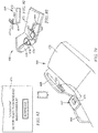
- a siderail assembly has upper and lower siderail body sections and a pair of linkage arms extending from a bottom of the lower siderail body section.
- Each of the linkage arms has X, Y and Z segments as shown in Fig. 43B .
- the Z segment is the vertically oriented segment
- the Y segment is the long horizontally oriented segment
- the X segment is the short horizontally oriented segment.
- Fig. 44 shows a model constructed in accordance with Figs. 43A and 43B .
- a siderail 310 is in a lowered position.
- the siderail 310 has first and second sections 312, 314 with the first section 312 being tucked behind the second section 314 in Fig. 44 .
- a user is grabbing part of the upper siderail body section 312 in preparation for raising the siderail 310.
- the user continues to raise the siderail 310 which is shown in an intermediate position.
- the siderail 310 is in the raised position having the first section 312 situated above the second section 314.
- a patient bed 320 has a patient helper 322 that is repositionable along a first laterally extending rail 324 adjacent a head end 326 of the bed 320.
- Bed 320 also has a GUI 328 that is repositionable along a second laterally extending rail 330 adjacent a foot end 332 of the bed 320.
- Bed 320 further has four siderails 334 that provide barriers along left and right sides of a mattress 336 of the bed 320 to prevent a patient from falling out of the bed.
- a GUI 338 is suspended from an end of the patient helper 322 and a grip handle 340 is built around the GUI 338. As shown in Fig.
- first portions 342 of each siderail 334 adjacent central regions along the left side of the bed are pivoted by about 90° relative to second portions 344 of the siderails to provide an opening between the siderails 334 through which the patient is able to egress from the bed 320.
- a patient bed 350 has a bed frame 352 that lacks traditional siderails, but instead has a pair of grab bars 354 on each side of bed frame 352.
- the grab bars 354 that can be seen on one side of the bed 350 are in storage positions below a mattress 356 of the bed 350.
- Mattress 356 has barrier air bladders 358, shown for example in Fig. 54 , that are situated along the sides of the mattress 356 and that are inflated to provide barriers 360 to inhibit the patient from falling out of the bed as shown, for example, in Fig. 51 .
- barrier air bladders 358 shown for example in Fig. 54 , that are situated along the sides of the mattress 356 and that are inflated to provide barriers 360 to inhibit the patient from falling out of the bed as shown, for example, in Fig. 51 .
- the barrier air bladders 358 at the sides of a foot section 362 of the mattress 356 are in a deflated state while the other barrier air bladders 358 remain inflated to provide respective barriers 360 in the hip and torso region of the patient.
- the barrier air bladders 358 along one of the sides of the mattress 356 are deflated to permit patient egress from the bed 350.
- the grab bars 354 are pivoted upwardly to use positions to be gripped by a patient situated between the grab bars 354.
- Fig. 54 shows how the bladders 358, in an inflated state, create a barrier 360 of about 6.5 inches high with respect to an upper surface 364 of the central region of the mattress.
- the bladders 358 are in a deflated state;
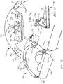
- a patient bed 370 is configured so that one of the siderails, in particular foot rail 372, is used as part of a patient lift system 374 when moved to a raised position over a central region of a mattress 376 of the bed 370.
- the lift system siderail 372 is moved to a position alongside the mattress 376 to serve as a traditional siderail for bed 370.
- Fig. 58 shows an exploded view of the lift system 374 of the bed 370.
- the lift system 374 includes a winch lift housing 378 that contains a winch motor (not shown), a bent steel tube fame 380 with casters 382, a hub 384, a clevis or pivot housing 386, a cast aluminum pivot arm 388 with an adjustment slot 390, an L-shaped aluminum extruded lift arm 392, a sling 394, a sling arm 396 with hooks 398, and a tether 400 having one end coupled to sling arm 396 and the other end coupled to the motor in winch lift housing 378.
- a winch lift housing 378 that contains a winch motor (not shown), a bent steel tube fame 380 with casters 382, a hub 384, a clevis or pivot housing 386, a cast aluminum pivot arm 388 with an adjustment slot 390, an L-shaped aluminum extruded lift arm 392, a sling 394, a
- tether 400 routes through the various components of lift system 374 between sling arm 396 and winch lift housing 378.
- the lower end of arm 388 is pivotably coupled to clevis 386 and the upper end of arm 388 is received inside the short segment of L-shaped arm 392.
- a threaded portion of T-handle 402 threads through an opening 404 of arm 392 and extends through slot 390 to engage the opposite wall of arm 388.
- the height of arm 392 and foot rail 372 above mattress 376 is adjustable by loosening T-handle 402, sliding arm 293 upwardly or downwardly on arm 388 to a desired height, and then tightening T-handle 402.
- arm 388 is coupled to clevis 386 for pivoting movement about a substantially horizontal axis to permit the foot rail 372, arm 392, and arm 388 to pivot as a unit between the lowered position, shown in Fig. 57 , and the raised position, shown in Fig. 56 .
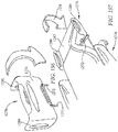
- clevis 386 is coupled to hub 384 for pivoting movement about a substantially vertical axis.
- hub 384 includes first and second hub pieces 384a, 384 b and clevis 386 includes first and second clevis pieces 386a, 386b.
- a bushing 406 provides the pivot joint between clevis 386 and hub 384.
- Arm 388 is mounted to clevis 386 between clevis pieces 386a, 386b by a main pivot pin 408.
- a T-handle 410 threads through an opening 412 in clevis piece 386b and is used to tighten against the lower end of arm 388 to retain arm 388 in its raised or lowered position.
- a T-handle 414 threads through another opening 416 in clevis piece 386b and is used to tighten against an upper surface of hub 384 to retain clevis 386 and the components of lift system 374 supported thereby in place relative to hub 384.
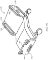
- a patient bed 420 has collapsible siderails 422 with a vertically oriented center post 424 serving as a siderail support in a central region of an upper frame 426 of the bed 420.
- Bed 420 further includes lift legs 428 at the corners of upper frame 426 of bed 420 that extend through respective apertures 430 formed in caster shrouds 432. Legs 428 extend and retract such that shrouds 432 and upper frame 426 move upwardly and downwardly relative to legs 428.
- caster shrouds 432 are coupled to the upper frame 426 to move upwardly and downwardly therewith.
- the upper frame When legs 428 are fully retracted, the upper frame is in a lowered position having casters 434 engaging a floor beneath the caster shrouds 432 as shown in Fig. 62 .
- casters 434 When legs 428 are extended from the fully retracted positions, casters 434 are moved upwardly out of contact with the floor.
- the siderails 422 are moved to collapsed positions and the center posts 424 are pivoted to a horizontally oriented storage position alongside the upper frame 426 as also shown in Fig. 62 .
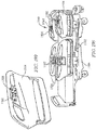
- a patient bed 440 has four siderails 442 each pivoted by a respective multi-axis joint 444 to an upper region of a respective lift post 446 at the corners of the bed 440.
- Multi-axis joints 444 permit movement of each siderail 442 from a use position extending generally horizontally alongside a mattress 448 of the bed 440 and an out-of-the-way position extending generally vertically upwardly from the upper region of a respective lift post 446 with a siderail body 450 oriented generally parallel with an endboard 452 of the bed as shown in Fig. 63 with regard to one of the siderails 442 at the left side of the figure.
- bed 440 is configured so that an upper frame 454 of the bed can be lowered with respect to the lift legs 446 so that casters 456 beneath caster shrouds 458 engage the floor.
- each of the caster shrouds 458 substantially cover from view a respective caster 456 that is braked when the caster shroud 458 is lowered and that is unbraked when the caster shroud 458 is raised.
- a mattress 460 has integrated siderail pads 462.
- pads 462 are included as part of a head section 464 of mattress 460.
- a bottom surface 466 of the mattress 460 has a pad storage recess 468 formed therein.
- pad 462 and recess 468 are rectangular in shape and are similarly sized so that pad 462 fills the entirety of recess 468 when in a storage positions.
- a strip 470 of material tethers pad 462 to the remainder of mattress 460.
- a patient bed 480 includes a repositionable GUI 482 which, in Fig. 68 , happens to be located at a foot end corner region of the bed 480.
- GUI 482 includes a touchscreen display 484 in a housing 486 that is mounted atop an arm 488.
- a lower end of arm 488 includes a movable mount 490 that slidably couples to an upper frame 492 of bed 480.
- the GUI 482 is located at the foot end of the bed 480 near a central region of a footboard 494 of the bed 480.
- the electronics of GUI 482 communicate wirelessly with other bed electronics of bed 480 in some embodiments. In such embodiments, there are no wires that route from the GUI to other portions of bed 480. In alternative embodiments, the electronics of GUI communicate via a wired connection with other bed electronics.
- touch screen display 484 has a set of controls 496 including inputs to raise, lower, extend and retract a foot section of bed 480, inputs to articulate head, thigh and foot sections of a mattress support deck of bed 480, inputs to raise and lower an upper frame and mattress of bed 480, and a nurse call input.
- a hand avatar 498 appears on the display 484.
- a patient is able to select controls on the GUI display 484 without touching the GUI 482 due to hand motions being detected within a sensor field 500, shown diagrammatically in Fig. 72 , of the GUI 482.
- a sensor that defines field 500 is situated within an aperture 502 provided in housing 486 above display 484.
- the avatar 498 is shown on display 484 based on the position of the patient's hand within field 500. After the patient moves the avatar 498 to a desired position having a finger hovering over the particular user input 496 of interest, the patient moves his or her hand or finger in the direction of display 484 to mimic a button press. This movement is detected in sensor field 500 and bed 480 responds by activating the feature or function chosen by the patient.
- bed 480 further includes a wireless patient remote control pendant 504 coupled to an upper rail 506 of a siderail 508 of the bed 480.
- the footboard 494 of the bed 480 has an integrated sequential compression system that communicates pressurized air via tubing to compression sleeves 510 that are attached to legs of the patient.
- pendant 504 includes a box-shaped main housing 512 with user inputs 514 on a front of the housing 512 and a C-shaped clip 516 extending from an arched track 518 that extends from a back of the housing 512.
- Clip 516 is sized and shaped to snap onto and off of rail 506.
- housing 512 When clipped to rail 506, housing 512 can be moved to desired position with track 518 sliding through clip 516 as the housing 512 is moved.
- Pendant 504 has electronics that communicate wirelessly with electronics elsewhere on bed 480. The wireless communication occurs in response to the patient pressing or otherwise selecting one of the user inputs 516 which in the illustrative example are membrane switches or buttons.
- a patient control module 620 has a C-shaped clamp 622 that is sized and configured to snap onto an upper rail 624 of a siderail 626.
- the patient control module 620 has a main body 628 with user input buttons 630, a nurse call pendant 632 that is detachable from the main body 628, and a spring loaded clamp 634 that retains the nurse call pendant 632 in place relative to the main body 628.
- the manufacturer of the nurse call pendant 632 is different than the manufacturer of main body 628 and clamp 634.
- an arm 636 extends from clamp 634 and enters into an interior region of main body 628.
- One or more springs (not shown) in the interior region of the main body 628 act upon arm 636 to bias clamp 634 toward main body 628.
- the clamp 634 is biased against one of the sidewalls of the pendant 632 and the other of the sidewalls of pendant 632 is urged against a sidewall of the main body 628.
- a bottom surface of pendant 632 rests atop an upper surface of arm 636 when pendant 632 is placed in the space between clamp 634 and main body 628.
- a first pendant 640 includes a spring loaded retainer 642 that holds a second pendant 644 in position relative to the first pendant 640.
- the first pendant 640 has bed control inputs 646 and the second pendant 644 having a nurse call button 648.
- Pendants 640, 644 may be made by different manufacturers.
- Retainer 642 includes a clamp arm 650 that is generally parallel with a sidewall of pendant 640.
- Retainer also has a pair of support arms 652 that each enter into an interior region of pendant 640.
- One or more springs (not shown) in the interior region of the pendant 640 act upon arms 652 to bias clamp arm 650 toward pendant 640.
- a patient bed 660 has a shelf 662 pivoted to a use position relative to a barrier, such as illustrative foot rail 664 of the bed 660, and has a port 666 on another barrier, such as a head rail 668 of the bed 660, that is used to charge wireless devices such as phones, tablet computers, and the like when the barriers are in raised positions extending upwardly with respect to a patient support surface (e.g., mattress) so that the port is accessible to a patient supported on the patient support surface.
- a phone 670 is resting on shelf 662 and is being charged via port 666.
- shelf 662 is pivotable relative to the foot rail 664 between a first position (in phantom) overlying a mattress 672 of the bed 660 and a second position (in solid) extending in an opposite direction away from the mattress 672.
- a control panel housing 674 is pivoted upwardly out of a recess 676 in the head rail 668 to a raised position.
- the control panel housing 674 carries caregiver controls 678 that face away from the mattress 672 when the control panel housing 674 is in the raised position.
- patient controls (not shown) on an edge of the control panel housing 674 are accessible to a patient on mattress 672 when housing 674 is in the raised position.
- rail 668 has caregiver controls and/or patient controls at locations spaced from housing 674 in some embodiments.
- a display screen 671 of the phone 670 includes text indicating that bed control software to control features and functions of bed 660 can be downloaded to the phone 670 and indicating that the phone is charging.
- a patient bed 680 includes a wireless pendant 682 that is used by a patient to control bed functions and a television 684 in the room.
- the bed 680 has an IR receiver 686 in a foot board 688 to receive signals from the wireless pendant 682 for control of the bed functions and features.
- the bed 680 further includes a flip over control panel housing 690 that is coupled to each head rail 692 and that has patient controls 694 located on a side of the control panel housing 690 as shown in Figs. 83 and 84 .
- the control panel housings 690 also each include caregiver controls 696 that face away from the associated head rail 692 when the respective housing 690 is moved to a storage position within a recess of the respective head rail 692.
- the caregiver controls 696 are accessible to a caregiver alongside bed 680 and the patient controls 694 are blocked from access by the head rail 692.
- the control panel housing 690 is flipped over out of the recess, the patient controls 694 are exposed for use by a patient.
- a patient bed 700 has a control unit 702 mounted to an end of an arm 704 that extends from a top of a foot board 706 toward a patient.
- the control unit 702 has a graphical display screen or GUI 708 and a motion detector or sensor (similar to that described above in connection with Figs. 70-72 ) to detect movement of a patient's hand at a distance from the screen 708.
- a hand avatar is shown on GUI 708 when the sensor senses the patient's hand.
- caregiver controls 710 are located on a side of the control unit 702 as shown in Fig. 85 .
- the control unit 702 has grip handles 712 located below the graphical display screen 708. In Fig. 86 , a patient is grabbing one of the grip handles 712 to assist with egress from the bed.
- a pair of patient beds 720 each have a caregiver GUI 722 located at an upper end of an arm 724 that couples, at its lower end, to a base 726 of the bed for sliding movement along a longitudinal dimension of the bed 720.
- Foot pedals 728 for bed control extend from the lower end of the arm 724.
- Each bed 720 also has a patient grip handle 730 extending from a hub 732 to which a head rail 734 of the bed 720 couples.
- a GUI housing 736 of GUI 722 has patient controls 738 on a back wall of the housing 736 that face toward a patient.
- one of the siderails 734 of the bed 720 includes an integrated urinal 739.
- a siderail 740 has an upper surface 742 formed with a trough 744 through which patient care lines 746 are routed from one end of the siderail 740 to the other end.
- the patient care lines 746 enter one end of the trough 744 through a notch 748 or an end opening 750 and exit the other end of the trough 744 through an end opening 752.
- a caregiver control panel 754 is flipped upwardly out of a recess 756 to a raised position.
- a patient bed 760 includes a U-shaped grab bar 762 arching between mounts 764 that are situated adjacent head end corner regions of a mattress 766.
- a control unit 768 extends over a patient from a central region of the U-shaped grab bar 762.
- the control unit 768 has caregiver controls 770 on a sidewall 772 thereof.
- the grab bar 762 includes hand grip areas 774 with bumps 776 adjacent each side of the control unit 768.
- an undersurface 778 of the control unit 768 includes a patient control panel 780, an air flow fan 782 on each side of the patient control panel 780, a nurse call button 784 above the patient control panel 780, and a light 786 with adjacent on/off switch 788 above the nurse call button 784.
- a patient is shown reaching upwardly to engage the patient control panel 780.
- An arrow 789 in Fig. 93 indicates that the U-shaped grab bar 762 can be moved in that direction relative to the pivot mounts 764 so as not to obstruct patient egress.
- a patient bed 790 has a patient helper 792 having a first arm portion 794 extending upwardly from a mount collar 796 that attaches to a horizontally oriented arched rail 798 located at a head end 800 of the bed 790, a second arm portion 802 extending in a generally horizontal cantilevered manner from an upper end of the first arm portion 794 over a head section 804 of a mattress 806 and mattress support deck 808 of the bed 790, a third arm portion 810 that telescopically extends and retracts relative to the second arm portion 802 (as indicated by the double headed arrow 812).
- Rail 798 is generally triangular in cross section and collar 796 is shaped complementary to the rail 798.
- Patient helper 792 includes a trapeze grab bar 814 hanging at a lower end of a tether 816 that extends downwardly from an end of the third arm portion 810.
- Patient helper 792 further includes an oxygen tank holder 818 defined by a cylindrical wall situated at an end of an arm 820 that extends from a bottom end of the first arm portion 794 of the patient helper 792.
- a bottom wall or cross member or other suitable stop (not shown) is provided at the bottom of tank holder 818 to prevent an oxygen tank from slipping out of the bottom of holder 818.
- the entire patient helper 792 is repositionable along the arched rail 798.
- the trapeze grab bar 814 is generally triangular in shape with tubular portions 814a, 814b, 814c. Tubular portion 814b has a pair of hand grip areas 822.
- the trapeze grab bar 814 also includes a triangular patient control housing 824 with patient controls 826.
- the arched rail 798 is generally triangular in cross section and the collar 796 is shaped complementary to the rail 798.
- a double headed arrow 828 in Fig. 96 indicates the ability to reposition the patient helper 792 along the arched rail 798.
- a patient bed 900 has a transparent patient control panel 902 mounted to an end of an articulated arm assembly 904 that has a first arm 906 extending upwardly from a head deck section 908 and a second arm 910 extending from an upper end of the first arm 906 over the head deck section 908.
- Patient control panel 902 and arm assembly 904 are repositionable as a unit along the frame, particularly head deck section 908, of bed 900.
- control panel 902 has graphical user inputs displayed in a first format for day time use.
- the transparent patient control panel 902 is in a night mode having the user inputs displayed in a second format.
- the images on the transparent patient control panel 92 are controlled via organic light-emitting diode/heads up display (OLED/HUD) technology.
- OLED/HUD organic light-emitting diode/heads up display
- the day mode and night mode of control panel 902 helps the patient to properly maintain their biological clock because of the visual feedback provided to the patient as to the time of day (e.g., day time or night time).
- a patient bed 920 has a caregiver control unit 922 having a housing 924 that serves as a central region of a footboard 926.
- a pair of arms 928 supports the footboard 926 relative to a foot deck section 930 of bed 920. Arms 928 are manually extendable and retractable relative to foot deck section 930.
- a caregiver inserts pillows into the gap created between the footboard 926 and a mattress (not shown but similar to those disclosed herein) supported on bed 920.
- the pillows increase the length of the patient support area on bed 920.
- a footboard panel or wing set 932 snaps onto the housing 924 of the caregiver control unit 922.
- the footboard panel 932 has a central recess 934 that receives a portion of the housing 924 and wings 936 on opposite sides of the recess 934.
- a back wall 938 of footboard panel 932 interconnects the wings 936.
- a patient bed 940 has a caregiver GUI 942 that is automatically pivoted in the direction of arrow 943 out of a recess 944 in a siderail 946 to an ergonomic use position in response to a caster brake pedal 948 being moved to a brake position to brake casters 949 of the bed 940.
- the caregiver GUI 942 is automatically pivoted in the direction of arrow 945 back into the recess 944 in the siderail 946 to a storage position in response to the caster brake pedal 948 being moved to a neutral or steer position.
- a controller (not shown) of bed 940 receives signals from one or more sensors (not shown), such as limit switches, to indicate the position of pedal 948 and then the controller signals a motor (not shown) to pivot GUI 942 in direction 943 or direction 945 as the case may be.
- a caregiver universal remote cart 950 is used to control a patient bed 951 and other patient care equipment in a patient room.
- the caregiver universal remote cart 950 has a GUI 952 mounted to a top of a pole 954, a tray 956 mounted to the pole 954 beneath the GUI 952, a base 958 with casters 960 coupled to a lower end of the pole 954.
- the base 958 having foot operated controls 962 or foot inputs to control features of the patient bed.
- the foot operated controls control used to raise and lower an upper frame of bed 951 relative to a base and to control tilting of the upper frame between Trendelenburg and reverse Trendelenburg positions.
- wireless signals 964 are transmitted between the caregiver universal remote cart 950 and some of the other equipment in the hospital room.
- bed control cart 950 is used for controlling features of patient bed 951 and includes wheeled base 958 with foot inputs 962, support 954 extending upwardly from wheeled base 958, and GUI 952 supported by support 954.
- GUI 952 is a touchscreen display that displays hand inputs such as icons and buttons that are selected by a caregiver to control features of bed 961 and to control features of other equipment in the patient room. While the present disclosure is intended to cover any and all graphical depictions on GUI 952 for providing hand inputs for controlling bed 951 and other medical equipment, some representative examples of suitable bed control screen shots providing hand inputs can be found in U.S. Patent No. 8,572,778 and in U.S. Patent Application Publication No. 2012/0089419 .
- GUI 952 displays data of an informational nature (e.g., bed data, head of bed angle, patient weight) on various screens in some embodiments. Exemplary details of the use of a GUI to control patient bed and devices other than patient beds can be found in U.S. Patent Application Publication No. 2014/0297327 .
- cart 950 includes circuitry 966 configured to send wireless signals, such as via transmitter 967, to control the features of bed 951 in response to use of each of the foot inputs or controls 962 and hand inputs from GUI 958 of bed control cart 950.
- circuitry 966 is housed in base 958 of cart 958.
- some or all of circuitry 966 is housed in the structure that carries GUI 958 at the upper region of support 954.
- some or all of circuitry 966 is housed in an interior region of tray 956 and/or support 954.
- Cart 950 also includes a battery 968 to provide power to circuitry 966 and to GUI 958 and foot controls 962.
- bed 951 includes circuitry 2102 that receives wireless signals from cart 950 such as via receiver 2104.
- circuitry 966 of cart 950 and circuitry 2102 of bed 951 is configured for bidirectional wireless communication with each other.
- transceivers 967, 2104 are provided, respectively.
- cart 950 and bed 951 it is within the scope of this disclosure for cart 950 and bed 951 to each have separate receivers and transmitters rather than transceivers 967, 2104.
- Circuitry 2102 of bed 951 is also coupled to user inputs 2106, motors 2108, a scale system 2110, a pneumatic system 2112, alarms 2114, an AC power plug 2116 and an input/output (I/O) port or module 2118.
- Port 2118 coupled either via a wired connection or a wireless connection to a network 2120 of a healthcare facility so that data from bed 951 can be communicated to computer devices (e.g., nurse call computers, EMR computers, ADT computers, locating and tracking computers, etc.) of network 2120.
- data from cart 950 is communicated to network 2120 via circuitry 2102 of bed 951.
- data is communicated to network 2120 from cart 950 without involving bed 951 in the communication path, such as by transmissions from transmitter 967 to a wireless access point of network 2120, for example.
- transmissions are sent from devices of network 2120 to cart 950 and/or bed 951.
- FIG. 210 for cart 950 and bed 951 are rudimentary in nature but, nonetheless, are illustrative of the relevant aspects disclosed herein.
- Examples of the circuitry and related components of some suitable hospital beds 950 can be found in " Service Manual, ProgressaTM Bed From Hill-Rom,” ⁇ 2013, Hill-Rom Services, Inc. ; “ Service Manual, TotalCare® Bed System From Hill-Rom,” ⁇ 2008, Hill-Rom Services, Inc. ; and “ Service Manual, VersaCare® Bed From Hill-Rom,” ⁇ 2008, Hill-Rom Services, Inc.
- foot inputs 962 control raising and lowering of an upper frame of the patient bed 951 relative to a base of patient bed 951.
- the foot inputs control tilting of the upper frame of the patient bed 951 between Trendelenburg and reverse Trendelenburg positions.
- foot inputs 962 control movements of mattress support sections (sometimes referred to as "deck sections") such as head, thigh and foot sections, relative to the upper frame.
- the hand inputs of GUI 958 control motors 2108 that may move mattress support deck sections of the patient bed 951.
- the hand inputs of GUI 958 control pneumatic system 2112 that operates to inflate and deflate portions of a mattress of the patient bed 951.
- the hand inputs control a mattress therapy function of a mattress of the patient bed 951.
- the mattress therapy functions include one or more of the following: a rotation therapy, an alternating pressure therapy, a percussion therapy, a vibration therapy, and a low airloss therapy.
- the hand inputs control a turn assist function of the patient bed 951.
- the hand inputs of GUI 958 control scale system 2110 of bed 951.
- circuitry 966 is configured to receive wireless communications from the patient bed 951.
- the wireless communications from patient bed 951 include information relating to one or more alarms 2114 occurring on patient bed 951 in some instances.
- GUI 958 displays information pertaining to the one or more alarms 2114.
- the wireless communications from patient bed 951 include information relating to a patient weight as measured by scale system 2110 of patient bed 951.
- the wireless communications from patient bed 951 include information received by patient bed 951 from network 2120.
- the hand inputs are usable to lockout functions of patient bed 951 from being controlled by user inputs 2106 on patient bed 951.
- each of the hand controls of GUI 958 and foot controls 962 are able to be locked out from use by user inputs 2106 on the patient bed 951.
- circuitry 966 is configured to send wireless signals to control features of at least one other piece of healthcare equipment in response to use of any one or more of the foot inputs 962 and the hand inputs of cart 950.
- circuitry 966 of the bed control cart 950 communicatively pairs with bed circuitry 2102 of bed 951 after the bed control cart 950 is brought into a patient room in which the patient bed 951 is located. Furthermore, circuitry 966 communicatively pairs with bed circuitry 2102 of other patient beds 951 in other patient rooms after the bed control cart 950 is brought into respective rooms of the other patient beds 951. At least one user input selection on the hand controls of the GUI 958 is a prerequisite to the communicative pairing between circuitry 966 and bed circuitry 2102 in some embodiments. Alternatively or additionally, at least one user input selection on the foot controls 962 is a prerequisite to the communicative pairing between circuitry 966 and bed circuitry 2102.
- At least one user input selection on at least one user input 2106 of patient bed 951 is a prerequisite to the communicative pairing between circuitry 966 and bed circuitry 2102.
- a caregiver PIN is required to be entered on GUI 950 to accomplish the pairing of circuitry 966 with circuitry 2102. It should be appreciated that, in some embodiments, until a successful pairing between cart 950 and bed 951 occurs, cart 950 cannot be used to control features of bed 951.
- a patient bed 970 has a control panel 972 that a caregiver uses to select a bed feature that the caregiver intends to operate hands free at a later time in the not too distant future.
- control panel 972 is coupled to an upper frame 974 of bed 970.
- the caregiver is shown repositioning a patient on a mattress 976 of the patient bed in preparation for a turn assist function of bed 970 that the caregiver has selected on control panel 972.
- the caregiver is shown moving his foot to interrupt a light curtain 978 that results in operation of the bed feature (turn assist in the illustrative example) that the caregiver previously selected using the control panel 972.
- Patient bed 970 therefore, has a sensor to sense presence of a user's foot in a designated region and movement of the user's foot into the designated region causes a preselected feature of the patient bed 970 to operate.
- the designated region corresponds to light curtain 978.
- a suitable sensor is an IR receiver that is mounted near one end of bed 970 and that receives light from an IR transmitter located near the opposite end of bed 970.
- a capacitive sensor or other type of proximity sensor is used in lieu of or in addition to the IR transmitter/receiver pair to sense the presence of the user's foot in the designated region.
- Control panel 972 is used to select the preselected feature from among a plurality of bed features to be operated subsequently by movement of the user's foot into the designated region.
- Bed 970 has a frame that includes a base frame and an upper frame supported above the base frame.
- Control panel 972 is coupled to the upper frame and the designated region is defined, such as by light curtain 978, beneath the base frame. Interruption of the light curtain 978 by the user's foot results in operation of the preselected feature.
- more than one preselected feature is able to be selected for operation in response to placement of the user's foot or really, any body part or object, into the designation region.
- hands free operation of any one or more bed features in this manner is only active for a short period of time (e.g., 2 to 5 seconds) after the preselected feature is selected by the user. That is, the user must initiate the preselected action within a timeout period. Once initiated, the action itself will in many instances, take longer than the timeout period.
- a caregiver GUI 980 has a control panel 982 that is used to control features and functions of a hospital bed (not shown, but similar to the various patient beds disclosed herein).
- a phone 984 has bed controls 986 displayed on its display screen for use in controlling features and functions of the hospital bed.
- GUI 980 and phone 984 can both be used by a caregiver to control a bed.
- the various icons on the display screens of GUI 980 and phone 984 are substantially the same. That is, controls 982 and controls 986 are substantially the same. It is contemplated by this disclosure that caregivers purchase the software application for their phones 984 from the manufacture of the beds to be controlled by the phone 984.
- a siderail 990 has a first style of caregiver control panel 992 mounted in a recess 994 (see Fig. 112 ) of a siderail body 996.
- a second style of caregiver control panel 998 is mounted to the siderail body 996 and pivoted out of the recess 994.
- Each of the control panels 992, 998 include a housing 1000 having a brow 1002 projecting from its upper end to inhibit a patient from accessing user inputs of the control panel 992, 998.
- a patient bed 1004 has caregiver control panels 1006 located on bottom portions of grip handles 1008 that extend from upper regions of a footboard 1010 toward a head end of the bed 1004.
- Fig. 114 is a top plan view of the patient bed 1004 showing a caregiver using one of the control panels 1006 of the footboard grip handles 1008.
- a head rail 1012 of the patient bed 1004 has a grip handle 1014 at its foot end that pivots about 90° relative to a siderail body 1016 of the head rail 1012 to assist in patient egress.
- a patient bed 1018 has a telescopic lift system 1020.
- a patient bed 1022 has an upper portion 1024 mounted to a first type of base and lift system 1026.
- the upper portion 1024 includes a mattress, a mattress support deck and associated framework, an upper frame and siderails.
- Fig. 118 shows more detail of the first type of base and lift system 1026 of the bed 1022.
- Base and lift system 1026 includes a base frame covered by a shroud, casters, and a pair of vertically oriented telescopic lifts.
- Fig. 120 is an enlarged perspective view of one of the vertical lift tubes 1028. As shown in Fig. 120 , each lift tube 1028 includes a coupler 1030 that attaches to a mating coupler 1032 (see Fig. 117 ) at the corner regions of upper portion 1024.
- upper portion 1024 is configured to attach to two different types of lift systems.
- a patient bed 1040 has a single lift column 1042 that extends vertically between a base frame 1044 and an upper frame 1046 of the bed 1040.
- a patient bed 1050 similar to the patient bed 220 of Figs. 23-26 has a vertically oriented spiral lift mechanism 1052 extending between a laterally extending base portion 1054 and an upper frame 1056 of the bed 1050 at each end of the bed 1050.
- the upper frame 1056 is moved to a lowered position relative to the base portions 1054 of the bed 1050.
- an upper rail 1058 of a siderail 1060 has a line management clip 1062 in an opened position pivoted upwardly out of a line receiving recess 1064 to allow patient care lines 1066 to be routed through the recess 1064.
- the line management clip 1062 is moved to a closed position to engage and retain the patient care lines 1066 in the recess 1064.
- a pair of line managers 1068 are each attached to a top of a respective siderail 1070 of a patient bed 1072.
- a notch 1069 is formed at a top of each manager 1068 for receipt of patient care lines.
- a double headed arrow 1074 indicates that the line manager 1068 is slideable along the top of the siderail 1070 for repositioning.
- a patient bed 1072 has a base 1074 with a central portion 1076 that raises and lowers relative to caster brackets 1078 (see Fig. 130 ) that are situated on opposite sides of the central portion 1076.
- a caregiver is stepping downwardly on a foot pedal 1080 to move the central portion 1076 of the base 1074 downwardly.
- Fig. 129 a caregiver is stepping downwardly on a foot pedal 1080 to move the central portion 1076 of the base 1074 downwardly.
- a caster 1082 is attached to an associated caster bracket 1078 and a linkage mechanism 1084 interconnects the caster bracket 1078 with the central portion 1076 of the base 1074 and allows for the central portion 1076 of the base to raise and lower relative to the caster bracket 1078 when the linkage mechanism 1084 is actuated by the foot pedal 1080 via rotation of the foot pedal 1080 in one direction or the other.
- a patient bed 1090 has an upper frame 1092 that includes longitudinal frame members 1094 that each have a central section 1096 dropped downwardly relative to head end and foot end portions 1098, 1100 of the longitudinal frame members 1094.
- a pair of sleep deck drives 1102 extend generally in opposite directions from a lateral frame member 1104 of the upper frame 1094 that extends between the central sections 1096 of the longitudinal frame members 1094.
- Upper ends of lift mechanisms 1106 attach to respective lateral frame members 1108 that extend between the respective portions 1098, 110 of the longitudinal frame members 1094.
- a patient bed 1110 has an exercise machine 1112 mounted to an upper frame 1114 of the bed 1110.
- Exercise machine 1112 has first and second upside down U-shaped frame members 1116 and a folding longitudinal arm assembly 1118 that interconnects frame members 1116.
- Arm assembly 1118 has a first arm 1120 and a second arm 1122 that are foldable at a hinge type joint 1124.
- Exercise machine 1112 includes a seat 1126 that has a U-shaped channel member 1128 on it bottom for mounting to arm 1122 of folding arm assembly 1118.
- Machine 1112 further has a foot board unit 1130 with a footboard panel 1132, a connector frame 1134 at one end of the panel 1132, and a pair of wheels 1136 at an opposite end of the panel as shown in Fig. 133 .
- a patient sits on seat 1126 and hooks their feet into loops or straps (not shown) provided on the inner surface of panel 1132 facing the patient. The patient then flexes and extends their legs to translate the seat 1126 back and forth along arm assembly 1118.
- seat 1126 has a pair of grip handles 1138 that are gripped by a caregiver standing alongside the bed to assist the patient during use of machine 1112 if needed.
- rollers or glide pads are provided inside channel member 1128 to facilitate the movement of chair 1128 along arm assembly 1118.
- chair 1126 swivels relative to channel member 1128 about a vertical axis to permit a patient to egress and ingress the chair 1126 with the chair 1126 facing toward a side of the bed 1110.
- a slot 1140 is formed in an end portion 1141 of a foot deck section 1142 of upper frame 1114 and a handle bar 1144 of connector frame 1134 of footboard unit 1130 inserts into slot 1140 to couple the footboard unit 1130 to the bed 1110.
- Panel 1132 is then rotated upwardly from the lowered position, shown in Fig. 135 , and locked into a raised use position, shown in Fig. 133 .
- Figs. 136 and 137 when the exercise machine 1112 is decoupled from the bed 1110 it is configured to be folded up for transport by a caregiver.
- a wheel is included in joint 1124 so that during transport, three wheels roll along the floor, including the two wheels 1136 attached to panel 1132 and the wheel included in joint 1124.
- a patient bed 1150 includes a foot rail 1152 that, in a raised position, has a foot pedal 1154 that a patient engages and moves back and forth with the patient's foot as part of physical therapy. It is contemplated by this disclosure that both foot rails 1152 have the pedal 1154 and associated physical therapy mechanism. As shown in Fig. 139 , a therapy device 1156 is located inside the foot rail 1152 between panels 1158 of the foot rail 1152. The therapy device 1156 includes a slotted plate 1160 having a slider 1162 that attaches to a rod 1163 of a gas cylinder damper 1164 and that slides along the plate 1160 within a slot 1166.
- the foot pedal 1154 has an arm 1168 that extends through a slot 1170 in one of the foot rail panels 1158 and pivotably couples to the slider 1162.
- the panel 1158 of the foot rail 1152 that has the slot 1170 also has a storage recess 1172 that receives the foot pedal 1154 for storage when not in use.
- a patient bed 1180 is shown with a patient lying on a mattress 1182 of the bed 1180 and using a pedal mechanism 1184 that is deployed from a footboard 1186 of bed 1180 for physical therapy.
- the pedal mechanism 1184 has a pair of pedals 1188 on opposite sides of a pedal support arm assembly 1190.
- the pedals 1188 are akin to bicycle pedals and are cycled around by the patient's feet during physical therapy.
- the pedal mechanism 1184 is also used for physical therapy while the patient is in a sitting position on the bed 1180 after the bed 1180 has been moved to a chair position.
- the footboard 1186 has a recess 1192 that receives the pedal mechanism 1184 for storage.
- the pedal mechanism 1184 is deployed out of the recess 1192 for use by a patient.
- a patient bed 1200 has a foot pad 1202 with a heel support 1204 and foot anchor straps 1206 attached to a foot board 1208 of the bed 1200.
- a patient's feet are anchored to the foot pad 1202 using straps 1206 while lying on the bed 1200.
- the patient flexes her knees to draw her body toward the footboard 1208 as part of physical therapy.
- the bed 1200 has a pair of grip handles 1209 that are grabbed by the patient during the physical therapy, if desired.
- the footboard 1208 has a graphical display screen 1207 that extends upwardly from a central region of the footboard 1208. It is contemplated by this disclosure that the display screen 1207 displays information and messages pertaining to the physical therapy.
- Fig. 147 shows the same bed 1018 that is shown in Fig. 116 .
- a pair of disposable drainage canisters 1210 of bed 1018 is shown.
- Canisters 1210 are attached to a mattress retention wall 1212 of the bed 1018 and are used for collection of fluids.
- an upside down U-shaped grab bar 1214 is coupled to a bracket 1215 extending from a base 1218 of the bed 1018 and is coupled to a chair 1216 situated adjacent to the bed 1018.
- a patient bed 1220 has a drainage bag holder 1222 at the foot end 1224 of an upper frame 1226 of the bed 1220.
- the drainage bag holder 1222 has a sensor 1228 that detects the presence of a drainage bag 1230 (see Fig. 150 ) on the holder 1222.
- the drainage bag holder 1222 has a vertically oriented plate 1232, a drainage bag bar 1234 that pivotably couples to pivot tabs 1236 extending from the plate 1234, and a limit switch 1228 (aka the sensor 1228 in the illustrative embodiment) that is received in a hole 1238 formed in the plate 1236.
- the limit switch 1228 has a lever 1240 that is contacted and moved to a closed position by an arm 1242 extending from a shelf 1244 of the drainage bag bar 1234 when a drainage bag 1230 is attached to the bar 1234.
- the drainage bag holder 1222 also has a pair of cosmetic trim pieces 1246 in the illustrative embodiment that are situated on plate 1232 between respective pairs of pivot tabs 1236.
- a patient bed 1250 has a footboard 1252 that is pivoted upwardly in the direction of the arrow 1254 into a position overlying a patient's legs so that the footboard 1252 serves as an overbed table for the bed 1250.
- An arm 1256 supports footboard 1252 for pivoting movement relative to an upper frame 1258 of bed 1250.
- a lower end of arm 1256 is situated between a mattress retaining wall 1260 of upper frame 1258 and a mattress 1262 of bed 1250.
- the footboard 1252 is moved back to its normal position in the direction of arrow 1264 to serve as a traditional footboard 1252.
- Fig. 152 a patient bed 1250 has a footboard 1252 that is pivoted upwardly in the direction of the arrow 1254 into a position overlying a patient's legs so that the footboard 1252 serves as an overbed table for the bed 1250.
- An arm 1256 supports footboard 1252 for pivoting movement relative to an upper frame 1258 of bed 1250.
- the footboard 1252 has a shallow recess 1266 formed therein to help retain items on the footboard 1252 when it is being used as an overbed table.
- a caregiver is using a control panel 1268 that is included as part of the footboard 1252.
- a footboard 1270 has a pair of posts 1272 extending downwardly from a main body 1274 of the footboard 1272.
- the posts 1272 are pivotably coupled to the main body 1274.
- the footboard 1270 is attached to a patient bed 1276 and is pivoted downwardly in the direction of arrow 1278 about the posts 1272 to serve as a foot extender for the bed 1276.
- the main body 1274 of footboard 1270 has pad retaining wings 1280 to help retain a mattress pad on the portion of main body 1274 extending between the wings 1280.
- a patient bed 1290 is in a chair position with a patient's feet resting atop a footboard 1292 that is attached to a foot section 1294 of the bed 1290 in a first orientation having a foot prop bulge 1296 in the footboard facing downwardly toward a floor.
- the patient's feet are resting atop the foot prop bulge 1296 when the footboard 1292 is attached to the foot section 1294 of the bed 1290 in a second orientation.
- Fig. 160 also shows the patient's feet resting atop the foot prop bulge 1296.
- the foot prop bulge 1296 prevents foot drop and enhances comfort for those patients who are shorter than others.
- a patient bed 1300 has a split foot board 1302 situated adjacent a foot end 1304 of the bed 1300 to serve as a traditional footboard.
- a first section 1306 of the split footboard 1302 is being pivoted about a vertical axis, as indicated by the double headed curved arrow 1308, around a corner of a foot section 1310 of the bed.
- the footboard section 1306 is situated alongside the foot section 1310 of the bed 1300 and has a grip handle panel 1312 of the footboard section 1306 pivoted upwardly to a raised position relative to another panel 1314 of the footboard.
- Grip handle pane 1312 is gripped by a patient during egress from bed 1300.
- a patient bed 1320 has a footboard 1322 that includes a plurality of segments 1324 that are telescopically coupled together.
- the footboard 1322 has a raised position in which the telescopic segments 1324 are in an expanded configuration as shown in Figs. 164 and 166 .
- the footboard 1322 also has a collapsed or lowered position having the telescopic segments 1324 retracted into an uppermost segment 1324 as shown in Figs. 165 and 167 .
- the lowermost segment 1324 has a pair of posts 1326 extending downwardly therefrom for receipt in sockets 1328 of a foot end frame member 1329 of bed 1320 as shown in Figs. 166 and 167 .
- a patient bed 1330 includes a footboard 1332 having a television unit 1334 moved upwardly to a raised position for viewing by a patient on the bed 1330.
- the footboard 1332 includes a main body 1336 that supports a pair of speakers 1338 for the sound of television unit 1334.
- the television unit 1334 has a lowered position stored inside the footboard 1332.
- Footboard 1332 includes a first panel 1340 with a decorative covering 1342 and a second panel 1344 with a decorative covering 1346.
- Second panel 1344 is formed to include a TV and speaker receiving recess 1348 that receives the television unit 1334 and speakers 1338 therein.
- First panel 1340 attaches to the second panel 1344 to retain the television unit 1334 and speakers 1338 in footboard 1332.
- a decorative cap 1359 attaches to a top of the television unit 1334 and aligns with a pair of handles 1337 of panel 1344 when the television unit 1334 is in the lowered position.
- a hospital bed 1360 includes an IV pole 1362 having a flexible upper segment 1364 that extends upwardly from a rigid tube 1366 (e.g., a steel tube). Segment 1364 telescopes into and out of tube 1366. Tube 1366 is coupled at its lower end to a mounting socket 1368 that has a notch 1369 which allows the IV pole 1362 to fold downwardly to a storage position. Hooks 1363 are mounted to an upper end of flexible segment 1364. As shown in Fig. 173 , a standard IV pole 1361 carrying a piece of equipment 1365 is being damaged due to contact of the pole 1361 or equipment 1365 with a head section 1367 of the bed 1360. In contrast, in Fig.
- the flexible segment 1364 deflects in response to the head section 1367 of the bed 1360 contacting the pole 1362 or the piece of equipment 1365 carried by the flexible segment 1364 of the IV pole 1362.
- the flexible segment 1364 is made of fiberglass or spring steel in some embodiments.
- a patient bed 1370 has an IV pole 1372 with a contact sensor (discussed below) that provides a signal to a bed controller (not shown) indicating that the IV pole 1372 is contacting an obstacle so that the bed controller can signal actuators (not shown) of the bed 1372 to take corrective action.
- a bed 1370' having an IV pole 1372' without any contact sensor has the pole 1372' being driven into a head wall unit 1373 due to tilting of an upper frame 1374 of the bed 1370'.
- the IV pole 1372 has a telescopic pole 1378 with segments 1378a, 1378b, 1378c, a coupling socket 1380, and a load cell 1382 adjacent to the coupling socket 1380.
- Load cell 1382 is the contact sensor in the illustrative embodiment.
- Load cell 1382 is fastened to a bracket 1384 at the bottom of socket 1380 via a pair of screws 1386 that extends through holes 1388 in bracket 1384 and threads into apertures 1390 of load cell 1382.
- a pivot pin 1392 couples a lower end of segment 1378c of pole 1378 to socket 1380.
- a notch 1394 is provided in socket 1394 to allow pole 1378 to fold down for storage on bed 1370.
- Table 1400 having information pertaining to bed exit and patient egress alert modes of a patient bed.
- Table 1400 has first, second, and third columns 1402, 1404, 1406.
- Each column 1402, 1404, 1406 has three rows with a middle or second row each having indicia associated with an exit/egress mode named in the first row.
- the first row reads "BED EXIT” and the third row reads "2 SENSITIVITIES, PATIENT SITS UP, PATIENT MOVES TO EDGE.”
- the first row reads "WANDERING ALERT” and the third row reads "SEPARATE FROM BED EXIT, ALERTS NURSE WHEN Pt.
- the first row reads "PATIENT EXIST ASSIST” and the third row reads "PATIENT ACTIVATES BUTTON, LOWERS FOOT RAIL * IF EQUIPPED, RAISES HEAD, LOWERS KNEE, INFLATES SEAT * IF EQUIPPED, ALERTS NURSE, BRIGHTENS NIGHT LIGHT.”
- a patient bed that includes a patient position monitoring system that has a first mode of operation in which an alarm is generated at the patient bed and an alert message is sent to a nurse call system in response to a threshold amount of movement of a patient relative to the patient bed.
- the patient position monitoring system also has a second mode of operation in which an alert is sent to the nurse call system but no alarm is generated at the patient bed in response to the threshold amount of movement of the patient relative to the patient bed.
- the second mode therefore, may be described as a "wander" mode and the alert sent to the nurse call system may be considered a "wander" alert.
- the threshold amount of the first and second modes corresponds to the patient being out of the patient bed.
- the patient position monitoring system related to table 1400 has a third mode of operation in which an alarm is generated at the patient bed and an alert message is sent to a nurse call system in response the patient moving by a lesser amount than the threshold amount relative to the patient bed.
- the lesser amount corresponds, for example, to the patient sitting up in the patient bed or moving to the edge of the patient bed. This corresponds to column 1402 of table 1400.
- the patient bed further includes a patient exit assist input that, when selected, results in one or more of the following actions by the patient bed: at least one siderail of the patient bed moves automatically from a raised position to a lowered position; a head section of a mattress support deck of the patient bed raises to a predetermined position if the head section is lower than the predetermined position when the patient exit assist input is selected; a thigh and foot section of the mattress support deck of the patient bed lower, possibly to a flat position, if they are raised when the patient exist assist input is selected; and/or at least one bladder of an air mattress is inflated to a target pressure if the bladder has a lower pressure than the target pressure when the patient exit assist input is selected.
- the at least one bladder includes, or is included in, a seat section of the air mattress.
- an exit assist alert is sent from the patient bed to a nurse call system in response to the selection of the patient exit assist input.
- a night light of the patient bed is illuminated brighter in response to the selection of the patient exit assist input.
- the patient exit assist input includes a button that may be selected by pressing the button.
- a button or icon on a touch screen that is touched would suffice just as well, as would other inputs such as switches, levers, knobs, and the like.
- a patient bed 1410 has the capability to project a lighted image 1412 onto a floor adjacent to the bed 1410 to indicate to a patient a location of a bed exit zone which corresponds to the area of the lighted image 1412.
- the words "BED NOT LOW” appear in the image 1412 to alert the patient and/or caregiver that an upper frame of the bed 1410 should be lowered prior to a patient exiting the bed.
- the words "EXIT ZONE" also appear in the lighted image in the illustrative example.
- the lighted image is generally semicircular in overall shape, but other shapes are within the scope of this disclosure, such as square, round, triangular, rectangular, trapezoidal, hexagonal, etc.
- a patient bed 1414 includes a footboard 1416 having an icon 1418 that illuminates when a bed exit alarm system of bed 1414 is armed.
- the icon 1418 provides a visual indication to the patient not to get out of the bed 1414.
- a patient bed 1420 includes a footboard 1422 having a set of icons 1424 that are illuminated green to indicate a satisfactory status of an associated monitored bed feature and that are illuminated a color other than green (e.g., amber or red) to indicate an unsatisfactory status of the associated monitored condition.
- the icons are unlit if the associated feature of the bed is not being monitored.
- the icons 1424 comprise translucent portions of a wall of the footboard 1422 and lights are situated in the footboard behind the translucent portions.
- the lights may comprise individual LED's of different colors for example (e.g., green and amber LED's behind each translucent portion) or multi-color LED's behind each translucent portion.
- a bed 1426 similar to the beds 720 of Fig. 87 , has the capability to project a set of icons 1428 onto the floor near a foot end 1427 of the bed 1426 and to project a message1429 near a side of the bed 1426.
- the icons 1428 indicate statuses of monitored features of the bed and the message advises the patient to call a nurse if the patient desires to get out of the bed 1426 in the illustrative example.
- the icons 1428 are illuminated green to indicate a satisfactory status of an associated monitored bed feature and are illuminated a color other than green (e.g., amber or red) to indicate an unsatisfactory status of the associated monitored condition.
- the icons are not projected onto the floor if the associated feature of the bed is not being monitored.
- a patient bed 1430 has a footboard 1432 that includes a built-in foot warmer (not shown).
- the foot warmer comprises a heater 2200 as shown in Fig. 211 .
- Bed 1434 is illustrated in Fig. 211 with components that are the same or substantially similar to those shown n Fig. 210 and so like reference numerals are used for like components and the descriptions need not be repeated.
- footboard 1432 is detachable from the frame of bed 1430 and so first and second electrical couplers 2202, 2204 are provided in bed 1434 in the illustrative embodiment to accommodate the coupling and decoupling of footboard 1432.
- Suitable couplers that mate automatically when a footboard is attached to a bed frame and that decouple automatically when a footboard is detached from a bed frame are shown and described in U.S. Patent No. 6,208,250 .
- a patient bed 1434 has a footboard 1436 with a camera module or unit 1438 extending upwardly from a central region of a foot board 1436.
- the camera module 1438 has a camera 1440 that faces toward a patient on the bed 1434 and a GUI display screen 1442.
- the bed has control circuitry (not shown) that commands the camera 1440 to take a picture of the patient at substantially the same time as a patient weight reading is taken using a weigh scale system (not shown) of the bed 1434 and the GUI display screen 1442 displays the picture that was taken.
- the weight reading and picture are transmitted from the circuitry of the bed 1434 for receipt by a remote computer.
- a patient bed 1444 has an RFID tag reader (not shown, but well known in the art) that reads RFID tags 1446 of equipment placed on the bed 1444 so that a weigh scale system (see block 2110 of Figs. 210 and 211 , for example) of the bed 1444 can recalculate a tare weight to account for the added equipment.
- RFID tag reader not shown, but well known in the art
- a weigh scale system see block 2110 of Figs. 210 and 211 , for example
- a mattress control box 1447 is an example of added equipment hanging on a footboard 1448 of the bed 1444 but the teaching of this disclosure regarding Figs. 186-188 is applicable to all equipment that is added to a patient bed.
- a cover 1449 is removed from tag 1446 to expose a universal serial bus (USB) connector 1450 of the tag 1446.
- the RFID tag 1446 is coupled to a USB port of a computer 1452 to be encoded with data to be transmitted wirelessly to bed 1444 and to have its battery (not shown, but well known in the art) charged.
- the data encoded or programmed into the RFID tag includes weight data of the equipment to which the RFID tag is to be coupled. Connectors and ports other than USB connectors and ports, are within the scope of this disclosure.
- Tag 1446 communicates wirelessly with the tag reader of bed 1444 to provide the weight data of the associated equipment to bed 1444. The tare weight of the scale system of bed 1444 is then updated based on the weight data transmitted from tag 1446.
- a siderail 1454 has a built in grab handle 1455, a channel 1458 to receive a shaped edge of a control pendant 1460, a recess and coupling bar 1456 for a urinal 1462, and a built in line manager 1464.
- a mattress 1466 is also shown.
- the present disclosure contemplates siderail 1454 having a urinal dock.
- the urinal dock includes a recess for a handle of the urinal 1462.
- Siderail 1454 includes coupling bar 1456 that extends across the recess to retain the handle of urinal 1462 in the recess when the urinal 1462 is docked to the siderail 1454.
- the recess is open at a top edge of the siderail 1454 so the handle can be moved into and out of the recess along a generally vertical path.
- grab handle 1455 of siderail 1454 is situated below the recess.
- Channel 1458 is complementary in shape to the shaped edge of the control pendant 1460.
- Line manager 1464 is located along a top edge of the siderail 1454 and comprises a notch that is situated alongside the opening to the recess.
- a patient bed 1470 includes a foam mattress 1472 having integral foam side bolsters 1474 extending upwardly along opposite sides of the mattress 1472.
- Bed 1470 also has a white noise generator/noise cancelation unit 1476 supported by an arm assembly 1478 above a head section 1479 of the bed 1470.
- a patient bed 1480 has sensors 1482 in surfaces, such as surfaces of one or more siderails 1484 and/or one or more endboards 1486, of the bed 1480 to sense whether the bed is clean or dirty. In some embodiments, the sensors 1482 detect cleaning agents.
- Bed 1480 also has a lighted sign 1488 on footboard 1486 of the bed 1480 that displays a message to indicate whether the bed 1480 is clean or dirty. Thus, lighted sing 1488 faces away from a mattress of bed 1480.
- sensors 1482 indicate the bed 1480 is clean and if a weigh scale system of bed 1480 indicates a low weight (e.g., low enough that it is assumed a patient is not on the bed), then the weigh scale of the bed 1480 is automatically zeroed.
- a patient bed 1490 includes a disinfectant mister system (not shown). As shown in Fig. 196 , each siderail 1492 of the bed 1490 has a mister spray nozzle 1494 through which a mist of disinfectant is delivered. In Fig. 197 , the mist is shown being delivered from the nozzle 1494 downwardly onto user inputs 1496 of the siderail 1492 to disinfect the user inputs 1496.
- a patient bed 1500 has directional ultraviolet (UV) lights 1502 included on siderails 1504 and a base 1506 of the bed 1500 for infection control.
- UV lights 1502 on siderails 1504 are located above user inputs 1508 so that the UV light rays from lights 1502 disinfect the user inputs 1508.
- the UV light 1502 on base 1506 also doubles as a night light for the bed 1500.
- the siderail 1504' has translucent grip portions 1510 and a steel frame 1512 with UV light emitting diodes (LED's) 1514 mounted thereto. The UV light rays from LED's 1514 pass through translucent grip portions 1510.
- LED's UV light emitting diodes
- a patient bed 1520 has an egress seat 1522 that deploys laterally outwardly from an upper frame 1524 of the bed 1520 in a direction substantially perpendicular to a long dimension of bed 1520.
- a patient is sitting on the deployed egress seat 1522.
- a transport chair 1526 (aka a "wheeled chair") has been wheeled up to the patient by a caregiver.
- the transport chair 1526 has horizontal arms 1528 that slide into channels 1530 situated at the sides of the egress seat 1522 so that the patient is surrounded by portions of the bed 1520 and the chair 1526 during egress from the bed 1520 to the chair 1526.
- the patient is shown sitting on a seat 1532 of the transport chair 1526.
- the horizontal arms 1528 of the transport chair 1526 are spaced from, and aligned with, the channels 1530 of the egress seat 1522.
- Arms 1528 are oriented generally horizontally and are configured so that the patient stands between the arms 1528 when moving from the egress seat 1522 onto seat 1532.
- the arms 1528 and channels 1530 are substantially at the same elevation and oriented horizontally when an upper frame of the bed 1520 is in a lowered position relative to a base of the bed 1520.
- a patient room 1540 has a 3-dimensional (3D) sensor 1542 mounted to a panel 1544 of a headwall unit 1546.
- a caregiver at a nurse's station 1547 is using a computer 1548 to view an image obtained by the 3D sensor 1542 in the room.
- the nurse station 1547 is remote from the room.
- the information displayed on a display screen 1550 of the computer 1548 prior to a remote weight reading of the patient being taken using the computer 1548 is shown.
- Fig. 209 the information displayed on the display screen 1550 after the weight reading is taken is shown.
Abstract
Description
- The present disclosure relates to controllers for patient beds and features of bed frames of patient beds that are typically found in healthcare facilities such as hospitals and nursing homes. More particularly, the present disclosure relates to bed frames having enhanced patient and caregiver interaction such as controlling overall bed functionality, siderail positioning for bed exit, patient repositioning within a bed, transfer of a patient from a bed, and patient therapy.
- An apparatus, system, or method may comprise one or more of the following features alone or in any combination.
- A bed control cart for controlling features of a patient bed may include a wheeled base with foot inputs, a support extending upwardly from the wheeled base, a GUI supported by the support, the GUI displaying hand inputs, and circuitry configured to send wireless signals to control the features of the bed in response to use of each of the foot inputs and hand inputs of the bed control cart.
- In some embodiments, the foot inputs may control raising and lowering of an upper frame of the patient bed relative to a base of the patient bed. Alternatively or additionally, the foot inputs may control tilting of the upper frame of the patient bed between Trendelenburg and reverse Trendelenburg positions.
- The wheeled base may include a set of casters. The support of the bed control cart may comprise a pole. The GUI may be mounted to an upper end or top of the pole. A tray may be mounted to the pole beneath the GUI.
- In some embodiments, the hand inputs may control motors that may move mattress support deck sections of the patient bed. Alternatively or additionally, the hand inputs may control a pneumatic system that may inflate and deflate portions of a mattress of the patient bed. For example, the hand inputs may control a mattress therapy function of a mattress of the patient bed. The mattress therapy functions may include one or more of the following: a rotation therapy, an alternating pressure therapy, a percussion therapy, a vibration therapy, and a low airloss therapy. Further alternatively or additionally, the hand inputs may control a turn assist function of the patient bed.
- In some embodiments, the hand inputs may control a scale system of the bed. The circuitry may be configured to receive wireless communications from the patient bed. The wireless communications from the patient bed may include information relating to one or more alarms occurring on the patient bed. The GUI may, in turn, display information pertaining to the one or more alarms. Alternatively or additionally, the wireless communications from the patient bed may include information relating to a patient weight as measure by a scale system of the patient bed.
- In some embodiments, the wireless communications from the patient bed may include information received by the patient bed from a network of a healthcare facility. The hand inputs may be usable to lockout functions of the patient bed from being controlled by user inputs on the patient bed. Optionally, each of the hand controls and foot controls may be able to be locked out from use by user inputs on the patient bed. Alternatively or additionally, the circuitry may be configured to send wireless signals to control features of at least one other piece of healthcare equipment in response to use of any one or more of the foot inputs and the hand inputs.
- In some embodiments, the circuitry of the bed control cart may communicatively pair with bed circuitry of the bed after the bed control cart is brought into a patient room in which the patient bed is located. Furthermore, the circuitry may communicatively pair with bed circuitry of other patient beds in other patient rooms after the bed control cart is brought into respective rooms of the other patient beds. At least one user input selection on the hand controls of the GUI may be a prerequisite to the communicative pairing between the circuitry and the bed circuitry. Alternatively or additionally, at least one user input selection on the foot controls may be a prerequisite to the communicative pairing between the circuitry and the bed circuitry. Further alternatively or additionally, at least one user input selection on at least one user input of the patient bed may be a prerequisite to the communicative pairing between the circuitry and the bed circuitry.
- A patient bed may have foot rails that may be movable by a patient in the bed to an out-of-the-way position to permit the patient to egress from the bed. The foot rails may slide relative to a bed frame of the patient bed in a longitudinal direction of the bed. A portion of the foot rails may slide relative to a head rail of the patient bed.
- A patient bed may have a head rail with a button that is pressed by a patient in the bed to cause motorized lowering of a foot rail of the patient bed.
- A patient bed may have a foot rail and linkage system that is manually slideable as a unit on a rail of an upper frame of a bed when a patient actuates a release lever of the foot rail.
- A patient bed may have a hub mounted to an upper frame of the patient bed. A head rail and a foot rail may each be pivotably coupled to the hub and may be moveable relative to the hub between respective raised and lowered positions.
- A patient bed may have a mattress support deck including a head section having turn assist panels that are cam driven to raised positions.
- A patient bed may have an upper frame and a graphical user interface (GUI) mounted to a top of an arm that has its bottom end coupled to the upper frame. The arm and GUI may be repositionable as a unit along the upper frame.
- In some embodiments, the GUI may comprise a transparent patient control panel mounted to the arm assembly. The transparent patient control panel may be operable in a day mode and a night mode. Images on the transparent patient control panel may be controlled via organic light-emitting diode/heads up display (OLED/HUD) technology. The arm may have a first arm segment that may extend upwardly from a head deck section and a second arm segment that may extend from an upper end of the first arm over the head deck section.
- A patient bed may have a siderail that moves to a raised position elevated over a central region of a mattress of the patient bed for use as part of a patient lift of the patient bed.
- A patient bed may have physical therapy equipment integrated therein. For example, the physical therapy equipment may be integrated into a siderail or footboard of the bed. The physical therapy equipment may be attachable to an upper frame of the bed.
- A patient bed may have lift posts at corners of an upper frame and siderails coupled to the lift posts by respective multi-axis joints.
- A mattress for a patient bed may have siderail pads coupled to a main mattress body and the main mattress body may have recesses in an undersurface thereof for storage of the siderail pads.
- A patient bed may have a GUI with a sensor to sense movements of a patient's hand at a distance so that a patient is able to control features of the patient bed without directly touching the GUI. In some embodiments, a hand avatar may be shown on the GUI when the sensor senses the patient's hand.
- A control module for a patient bed may include a first pendant and a second pendant that may be held in place against the first pendant by a spring loaded clamp. In some embodiments, the first pendant may have bed controls and the second pendant may have a nurse call button.
- A patient bed may have a port that may be connectable to a handheld electronic device to recharge the handheld electronic device and to download bed control software to the handheld electronic device. The handheld electronic device may comprise a phone or a tablet computer, for example.
- In some embodiments, the patient bed may include a frame that may have a barrier extending upwardly with respect to a patient support surface and the port may be provided on the barrier. For example, the barrier may comprise a siderail. Optionally, user inputs may be coupled to the siderail to control one or more features of the patient bed. The siderail may comprise a first siderail and the patient bed may further include a shelf and a second siderail that may be spaced from the first siderail. The shelf may be attached to the second siderail, for example. The shelf may be pivotable relative to the second siderail to a plurality of positions. The patient bed may include a mattress and the shelf may be pivotable relative to the second siderail between a first position overlying the mattress and a second position extending in an opposite direction away from the mattress.
- In some embodiments, a control panel housing may be pivotable relative to the siderail between a raised position and a lowered position. The control panel housing may move upwardly out of a recess in the siderail when moving from the lowered position to the raised position. The patient bed may include a mattress and the control panel housing may carry caregiver controls that may face away from the mattress when the control panel housing is in the raised position and the control -panel housing may have patient controls that may be provided on an edge of the control panel housing.
- A patient bed may have a control module with caregiver controls on one surface and having patient controls on another surface.
- A patient bed may have a control module that may include a generally vertical arm extending upwardly from a base of the patient bed, a GUI mounted to an upper end of the arm, and at least one foot pedal mounted to a lower end of the arm. The GUI and at least one foot pedal may be used to send wireless signals to other bed electronics of the patient bed. In some embodiments, the control module may be repositionable along the base. Alternatively or additionally, a housing for the GUI may have patient controls on a back wall thereof.
- A siderail may have a trough along its upper edge for receipt of patient care lines.
- A patient bed may have a GUI in a siderail that may deploy automatically out of a cavity in a siderail to a use position in response to a brake pedal of the patient bed being moved to a brake position to brake casters of the patient bed. The GUI may be moved automatically back into the cavity in response to the brake pedal being moved to another position other than the brake position.
- A patient bed may have a sensor to sense presence of a user's foot in a designated region and movement of the user's foot into the designated region may cause a preselected feature of the patient bed to operate.
- The patient bed may further have a control panel that may be used to select the preselected feature from among a plurality of bed features to bed operated subsequently by movement of the user's foot into the designated region. The patient bed may have a frame that may include a base frame and an upper frame supported above the base frame. The control panel may be coupled to the upper frame. The designated region may be defined by a light curtain beneath the base frame. Interruption of the light curtain by the user's foot may result in operation of the preselected feature. For example, the patient bed may have a mattress and the preselected feature may include a turn assist function of the mattress.
- A patient bed may have a siderail with an integrated line clip.
- A patient bed may have a drainage bag holder including a bar and a sensor to sense when a drainage bag is coupled to the bar.
- The drainage bag holder may be located at a foot end of an upper frame of the bed. The drainage bag holder may include a substantially vertically oriented plate and the bar may be pivotably coupled to the substantially vertically oriented plate. In some embodiments, pivot tabs may extend from the plate and the bar may be pivotably coupled to the pivot tabs. The drainage bag holder may further include a pair of cosmetic trim pieces that may be situated on the substantially vertically oriented plate between respective pairs of pivot tabs.
- In some embodiments, the sensor may include a limit switch that may be received in a hole formed in the substantially vertically oriented plate. The limit switch may have a lever that is contacted and moved to a closed position by an arm that may extend from a shelf of the bar when the drainage bag is attached to the bar.
- A patient bed may have a footboard that flips up to serve as an overbed table.
- A patient bed may have a footboard that flips down to serve as a foot deck extension for the patient bed.
- A patient bed may have a footboard with telescopic segments that may move between extended and retracted positions.
- A patient bed may have a footboard with an integrated television unit. The television unit may store downwardly in a footboard body and may raise upwardly out of the footboard body for viewing.
- A patient bed may project a lighted bed exit zone image onto a floor at a side of the bed.
- In some embodiments, the lighted bed exit zone image may include text that may indicate a status of a position of an upper frame of the bed relative to a lower frame of the bed. For example, the text may include the words "BED NOT LOW" if the upper frame of the bed is not in a lowered position relative to the lower frame. The words "EXIT ZONE" also may appear in the lighted bed exit zone image in some embodiments. The lighted bed exit zone image may be generally semicircular in overall shape but all other shapes are within the scope of this disclosure.
- A patient bed may light up an icon on a footboard to notify a patient not to get out of the bed.
- A patient bed may light up icons on a footboard to indicate a status of monitored features of the patient bed.
- The icons may be illuminated green to indicate a satisfactory status of an associated monitored bed feature. The icons may be illuminated a color other than green to indicate an unsatisfactory status of the associated monitored condition. The icons may be unlit if the associated feature of the bed is not being monitored. The icons may comprise translucent portions of a wall of the footboard. The patient bed may further include lights that may be situated behind the translucent portions.
- A patient bed may project icons onto a floor near a foot end of the bed and may project a message onto the floor near a side of the bed.
- In some embodiments, each of the icons may indicate a status of a respective monitored feature of the bed. The message may advise the patient to call a nurse if the patient desires to get out of the bed. The icons may be illuminated green to indicate a satisfactory status of an associated monitored feature. The icons may be illuminated a color other than green to indicate an unsatisfactory status of the associated monitored feature. In some embodiments, each icon is not projected onto the floor if the associated feature of the bed is not being monitored.
- A patient bed may have a footboard with a foot warmer.
- A patient bed may have a camera that automatically takes a picture of a patient on the bed when a weight scale reading is taken. In some embodiments, the weight reading and the picture may be transmitted from the bed to a remote computer.
- A patient bed may have sensors in surfaces of the bed to sense whether the bed is clean or dirty and may have a display to indicate whether the bed is clean or dirty.
- In some embodiments, the surfaces of the bed having at least one of the sensors may include a surface of a siderail of the bed. Alternatively or additionally, the surfaces of the bed having at least one of the sensors may include a surface of an endboard of the bed. In some embodiments, the sensors may detect cleaning agents. The patient bed may include a lighted sign that may display a message to indicate whether the bed is clean or dirty. The lighted sign may be coupled to a footboard of the bed, for example. The lighted sign may face away from a mattress of the bed. In response to the sensors indicating that the bed is clean and in response to a weigh scale system indicating a patient is not on the bed, the weigh scale system may be automatically zeroed.
- A patient bed may have nozzles through which a disinfectant mist is sprayed onto surfaces of the bed.
- A patient bed may have integrated UV lights to disinfect surfaces of the bed.
- A patient bed may have an egress seat that may deploy out of an upper frame of the bed for a patient to sit during egress. A wheeled chair may dock with the egress seat. The wheeled chair may have arms that may be received by channels at the sides of the egress seat when the wheeled chair is docked to the egress seat.
- In some embodiments, the egress seat may deploy laterally outwardly from the upper frame in a direction substantially perpendicular to a long dimension of the bed. The arms may be configured so that the patient stands between the arms when moving from the egress seat onto a set of the wheeled chair. The arms and channels may be substantially at the same elevation and oriented horizontally when an upper frame of the bed is in a lowered position relative to base of the bed.
- A patient bed may have a frame, a siderail that may be coupled to the frame and that may be moveable relative to the frame between a raised position and a lowered position, and an egress handle that may be movable upwardly out of a top opening of the siderail from a storage position to a use position. An upper end region of the egress handle may be gripped by a patient during egress from the bed when the siderail is in the lowered position.
- The siderail may comprise a foot rail and the patient bed may further include a head rail that may be coupled to the frame. The siderail may include a siderail body that may have a channel and the egress handle may be received in the channel for movement between the storage and use positions. The channel may be inclined such that the egress handle may move within the channel along a path that is neither horizontal nor vertical.
- The egress handle may have a recess that may facilitate the patient gripping the upper end region. The patient bed may further include a lock to lock the egress handle in the raised position relative to the siderail.
- In some embodiments, the patient bed may further have a second egress handle that may be movable relative to the siderail. For example, the second egress handle may be extendable horizontally from a head end of a body of the siderail to provide a grip handle for use by a patient during egress from the bed when the siderail is in the raised position.
- A patient bed may include a frame and a siderail that may be coupled to the frame. The siderail may have a main body and a shelf may be coupled to the main body. The shelf may have a use position extending from the siderail in a cantilevered manner. The patient bed may also have an inductive charger that may be coupled to the shelf. The inductive charger may be operable to inductively recharge electrical devices placed upon the shelf.
- The shelf may be movable relative to the siderail between the use position and a storage position. The inductive charger may be situated beneath an upper surface of the shelf. For example, the inductive charger may be situated in an interior region of the shelf. The inductive charger may be supported by an upper surface of the shelf. For example, the inductive charger may be embedded in a recess in the upper surface of the shelf. In such embodiments, an upper surface of the inductive charger and the upper surface of a remainder of shelf around the recess may be substantially coplanar. The electrical devices that the inductive charger may be operable to inductively recharge include one or more of the following: a smart phone, a tablet computer, and a laptop computer.
- A patient bed may include a frame that may have an upper frame and generally vertical lift legs at corners of the upper frame. At least one caster shroud may have at least one aperture through which a corresponding one of the lift legs may extend.
- The lift legs may extend and retract such that the at least one shroud and the upper frame may move upwardly and downwardly relative to the lift legs. The patient bed may have at least one caster beneath the at least one caster shroud and when the lift legs are fully retracted, the upper frame may be in a lowered position having the at least one caster engaging a floor beneath the at least one caster shroud. When the lift legs are extended from the fully retracted position, the at least one caster may be moved upwardly out of contact with the floor. The at least one caster shroud may be coupled to the upper frame to move upwardly and downwardly therewith as the lift legs extend and retract.
- A patient bed may include a frame, a footboard that may be coupled to the frame, an arm that may extend from the footboard over a patient support surface of the frame, and a control unit that may be mounted to an end of the arm. The control unit may include a graphical user interface (GUI) and a sensor to sense movements of a patient's hand at a distance so that a patient may be able to control features of the patient bed without directly touching the GUI.
- In some embodiments, a hand avatar may be shown on the GUI when the sensor senses the patient's hand. The control unit may include at least one grip handle arranged to be grabbed by a patient during egress from the patient bed. The at least one grip handle may be located below the GUI. The patient bed may further include caregiver controls that may be located on a side of the control unit.
- A patient bed may include a frame that may have a first end and a second end. The first end of the frame may include a laterally extending rail. A collar may be mounted to the rail and may be repositionable along the rail. An oxygen tank holder may be attached to the collar to move with the collar along the rail.
- In some embodiments, the oxygen tank holder may include a cylindrical wall. The oxygen tank holder may be offset from the collar by an arm. The rail may be arched in some embodiments. The rail may be generally triangular in cross section and the collar may be shaped complementary to the rail
- The patient bed may further include a patient helper that may have a first arm portion that may extend upwardly from the collar and a second arm portion that may extend in a generally horizontal cantilevered manner from an upper end of the first arm portion over a patient support surface of the frame. The patient helper may further include a third arm portion that may telescopically extend and retract relative to the second arm portion.
- In some embodiments, the patient helper may include a grab bar that may hang at a lower end of a tether that may extend downwardly from an end of the third arm portion. The grab bar may be generally triangular in shape. The grab bar may include a tubular portion that may have a pair of hand grip areas. The grab bar may include a patient control housing with patient controls that may be used to control one or more functions of the patient bed.
- A patient bed may include a patient position monitoring system that may have a first mode of operation in which an alarm may be generated at the patient bed and an alert message may be sent to a nurse call system in response to a threshold amount of movement of a patient relative to the patient bed. The patient position monitoring system may have a second mode of operation in which an alert may be sent to the nurse call system but no alarm may be generated at the patient bed in response to the threshold amount of movement of the patient relative to the patient bed.
- In some embodiments, the patient position monitoring system may have a third mode of operation in which an alarm may be generated at the patient bed and an alert message may be sent to a nurse call system in response the patient moving by a lesser amount than the threshold amount relative to the patient bed. The lesser amount may correspond, for example, to the patient sitting up in the patient bed or moving to the edge of the patient bed. The threshold amount of the first and second modes may correspond to the patient being out of the bed, if desired.
- The patient bed may further include a patient exit assist input that, when selected, may result in at least one siderail of the patient bed moving automatically from a raised position to a lowered position. Alternatively or additionally, selection of the patient exist assist input may cause a head section of a mattress support deck of the patient bed to raise to a predetermined position if the head section is lower than the predetermined position when the patient exit assist input is selected. Alternatively or additionally, selection of the patient exit assist input may cause a thigh and foot section of a mattress support deck of the patient bed to lower if they are raised when the patient exist assist input is selected. Alternatively or additionally, selection of the patient exit assist input may cause at least one bladder of an air mattress to be inflated to a target pressure if the bladder has a lower pressure than the target pressure when the patient exit assist input is selected. In some embodiments, the at least one bladder may include or be included in a seat section of the air mattress.
- In some embodiments, an exit assist alert may be sent from the patient bed to a nurse call system in response to the selection of the patient exit assist input. Alternatively or additionally, a night light of the patient bed may be illuminated brighter in response to the selection of the patient exit assist input. In some embodiments, the patient exit assist input may include a button that may be selected by pressing the button.
- According to this disclosure, a system may include a patient bed that may include a scale system and a radio frequency identification (RFID) tag reader. The system may also have one or more RFID tags that may be programmable with equipment weight data. The RFID tags may be attachable to respective equipment to be added to the patient bed. The RFID tag reader may read the RFID tags of the equipment added to the bed. In response to the RFID tag reader reading the RFID tag of corresponding equipment added to the bed, the scale system may recalculate a tare weight to account for a weight of the equipment added to the bed.
- A mattress control box may comprises the equipment added to the bed although the RFID tags may be used in connection with any desired equipment that may be added to a bed. In some embodiments, each of the RFID tags may include a connector, such as a universal serial bus (USB) connector. Each of the RFID tags may include a cover that may be removable from the remainder of the respective RFID tag to expose the USB connector.
- The may further include a computer and the USB connector of the RFID tag may be coupled to a USB port of the computer to be programmed by the computer with the equipment weight data of respective equipment. Alternatively or additionally, the USB connector of the RFID tag may be coupled to a USB port of the computer to have a battery of the RFID tag charged.
- Also according to this disclosure, a patient bed may include a siderail that may have a urinal dock. The urinal dock may include a recess for a handle of a urinal. The siderail may include a coupling bar that may extend across the recess to retain the handle of the urinal in the recess when the urinal is docked to the siderail. The recess may be open at a top edge of the siderail.
- In some embodiments, the siderail may further include a grab handle that may be below the recess. Alternatively or additionally, the siderail may include a channel that may be configured to receive a portion of a control pendant alongside the recess. For example, the channel may be complementary in shape to a shaped edge of the control pendant. If desired, a top edge of the siderail may include a line manager. The line manager may comprise a notch that may be situated alongside an opening to the recess that may be located at the top edge of the siderail.
- The invention will now be further described by way of example with reference to the accompanying drawings, in which:
-
Fig. 1 is a perspective view of a patient bed having four siderails including a pair of foot rails that each overlap a respective head rail of a pair of head rails, each foot rail being manually movable by a patient; -
Fig. 2 is a perspective view of the bed ofFig. 1 showing a patient being supported by the bed and showing the foot rails in a first position blocking egress of the patient from the bed; -
Fig. 3 is a perspective view of the bed, similar toFig. 2 , showing the patient having manually moved one of the foot rails to a second position, a foot end of the foot rail having been translated along an upper frame of the bed and a head end of the foot rail having been translated along the head rail; -
Fig. 4 is a perspective view of the bed, similar toFig. 3 , showing the patient having further manually moved one of the foot rails to a third position so that the patient is able to egress from the bed, the foot end of the foot rail having been translated further along the upper frame of the bed and the head end of the foot rail having been translated further along the head rail; -
Fig. 5 is a perspective view of another patient bed having four siderails including a pair of foot rails that each overlap a respective head rail of a pair of head rails, a foot end of each foot rail having a downwardly extending arm that carries an anti-friction element, such as a roller, that is received in a slot formed in a frame member of an upper frame of the bed, and a head end of each foot rail including a slider that couples to an elongated middle tube of the associated head rail; -
Fig. 6 is a perspective view showing one of the foot rails in an extended position relative to the associated head rail such that the slider is near a foot end of the head rail; -
Fig. 7 is a perspective view showing the foot rail moved to a retracted position relative to the head rail such that the slider is near a head end of the head rail; -
Fig. 8 is a perspective view of another patient bed having a button on a head rail that is pressed by a patient to initiate motorized lowering of an associated foot rail; -
Fig. 9 is an enlarged side view of the button ofFig. 8 ; -
Fig. 10 is a perspective view showing the foot rail having moved to a lowered position to permit patient egress from the bed; -
Fig. 11 is a perspective view of a portion of another patient bed having a foot rail with a lever that is accessible in a hand hole and that is used by a patient to release the foot rail for translational movement along a frame of the bed, a grip handle over the hand hole having a stepped bottom surface to provide grip areas for the patient to hold onto while moving the foot rail in increments toward a head end of the bed; -
Fig. 12 is a perspective view of the patient bed ofFig. 11 showing the foot rail having been moved out of the way toward the head end of the bed to permit patient egress from the bed and showing a pendulum cup holder on one of the head rails that maintains a drink cup in a vertical orientation even when the head section and head rails are raised; -
Fig. 13 is a perspective view of another patient bed showing a foot rail being rotated by a patient about a hub to a vertical position to permit patient egress from the bed, a head rail also being coupled to the hub; -
Fig. 14 is a side view of the foot rail, the head rail, and the hub showing the foot rail and the head rail each being in a respective lowered position; -
Fig. 15 is a perspective view of a mattress support deck showing left and right turn assist panels coupled to a head section of the deck and showing the left turn assist panel being articulated upwardly by a cam attached to a longitudinally extending shaft; -
Fig. 16 is a perspective view of a patient bed that includes the mattress support deck ofFig. 15 showing a mattress having a portion lifted upwardly by the articulated left turn assist panel; -
Fig. 17 is perspective view of a portion of another patient bed showing head and foot rails on one side of a mattress remaining in horizontal alignment even though a head section of a mattress is raised and showing a head rail on an opposite side of the mattress including a head rail portion that pivots upwardly to provide additional egress barrier coverage in the region of the raised head section; -
Fig. 18 is a perspective view of one of the head rails ofFig. 17 showing a push button near a head end of the head rail, a patient control panel extending laterally from a foot end of the head rail, and a set of caregiver controls on an inclined surface near the foot end of the head rail; -
Fig. 19 is a side view of the portion of the patient bed ofFig. 17 showing the head rail portion pivoting upwardly automatically in response to the head section of the mattress being raised; -
Fig. 20 is a perspective view of another patient bed showing a foot rail in a lowered position and having an extendable egress handle raised upwardly within an inclined channel formed in a foot rail body to provide a grip handle for use by a patient egressing from the bed when the foot rail is in the lowered position; -
Fig. 21 is a side view of the foot rail ofFig. 20 showing the extendable egress handle raised upwardly within the inclined channel and showing a second egress handle that is extendable horizontally from a head end of the foot rail to provide a grip handle for use by a patient egressing from the bed when the foot rail is in a raised position; -
Fig. 22 is an enlarged perspective view of the extendable egress handle and the inclined channel that guides the movement of the extendable egress handle; -
Fig. 23 is a perspective view of a portion of yet another patient bed showing head and foot rails each comprising a curved flexible panel and showing a pair of curved guide posts that are located between respective head and foot rails to provide guide channels for a head end of the respective foot rail and a foot end of the respective head rail, a head board having guide channels for head ends of the head rails, a foot board having guide channels for foot ends of the foot rails, and a pair of curved control panels that are extendable from channels formed at upper end regions of the guideposts; -
Fig. 24 is a side view of the portion of the patient bed ofFig. 23 showing the head and foot rails in respective lowered positions and showing the guide post folded downwardly to a storage position; -
Fig. 25 is a diagrammatic end view of part of the portion of the bed to shown the amount of curvature of one of the siderails; -
Fig. 26 is a perspective view of a patient bed containing the portion ofFig. 23 showing the foot rails in lowered positions and showing the head rails in raised positions; -
Fig. 27 is a perspective view of a portion of another patient bed having a head rail with a foot end portion pivoted to a head end portion for movement about a generally vertical pivot axis; -
Fig. 28 is a perspective view, similar toFig. 27 , showing the foot end portion of the head rail pivoted by about 90° relative to the head end portion of the head rail so that the foot rail portion extends away from an associated mattress to provide a grip handle for patient egress; -
Fig. 29 is a perspective view of another patient bed having four siderails that each include an upper section that moves relative to a lower section from a raised position to a lowered position such that when the upper section is in the lowered position, the siderail is compact and can be rotated outwardly away from the mattress and then slid underneath the mattress for storage in an orientation substantially parallel with the mattress; -
Fig. 30 is a perspective view showing a foot rail of the siderails in the storage position; -
Fig. 31 is a perspective view, similar toFig. 30 , showing the foot rail pulled out from under the mattress and rotated slightly upwardly; -
Fig. 32 is a perspective view, similar toFig. 31 , showing the foot rail oriented vertically with the upper section raised relative to the lowered section; -
Fig. 33 is a perspective view of still another patient bed; -
Fig. 34 is an end elevation view of the bed ofFig. 33 showing that the bed has expandable width siderails and a repositionable caregiver graphical user interface (GUI) at the foot end of the bed adjacent a central region of a footboard; -
Fig. 35 is a perspective view of the bed ofFig. 33 showing the GUI moved to a corner region of an upper frame of the bed, a fold out overbed table in a use position, and showing a patient's feet located against a footboard that includes a foot massager; -
Fig. 36 is a perspective view of the bed ofFig. 33 showing one of the foot rails lowered for patient egress having a first portion of foot rail separated from and situated below a second portion of the foot rail and showing a grip bar connected to a chair and to a base frame of the bed; -
Fig. 37 is a perspective view, similar toFig. 36 , showing the patient gripping a handle of the second portion of the foot rail and gripping a handle of the head rail in preparation for standing up from the bed; -
Fig. 38 is a perspective view, similar toFig. 36 , showing the patient in a standing position and using the grip bar that interconnects the base frame of the bed and the chair; -
Fig. 39 is an end elevation view of a mattress support deck, a mattress and a pair of siderails, showing one of the siderails pivoting toward a position parallel with an upper surface of the mattress for eventual storage under the mattress support deck; -
Fig. 40 is a perspective view of a model constructed in accordance withFig. 39 showing a siderail in a storage position beneath a section of the mattress support deck; -
Fig. 41 is a perspective view, similar toFig. 40 , showing the siderail being pulled out from under the mattress support deck and being pivoted partially toward a raised position; -
Fig. 42 is a perspective view, similar toFig. 41 , showing the siderail in the raised position; -
Fig. 43A is a perspective view of a siderail assembly having upper and lower siderail body sections and a pair of linkage arms extending from a bottom of the lower siderail body section; -
Fig. 43B is a perspective view of one of the linkage arms showing that the linkage arm has X, Y and Z segments; -
Fig. 44 is a perspective view of a model constructed in accordance withFigs. 43A and 43B showing the siderail in a lowered position; -
Fig. 45 is a perspective view, similar toFig. 44 , showing a user grabbing part of the upper siderail body section in preparation for raising the siderail; -
Fig. 46 is a perspective view, similar toFig. 45 , showing the user raising the siderail to an intermediate position; -
Fig. 47 is a perspective view, similar toFig. 46 , showing the siderail in the raised position; -
Fig. 48 is a perspective view of another patient bed showing a patient helper that is repositionable along a first laterally extending rail adjacent a head end of the bed, a GUI that is repositionable along a second laterally extending rail adjacent a foot end of the bed, and four siderails providing barriers along left and right sides of a mattress of the bed to prevent a patient from falling out of the bed; -
Fig. 49 is a perspective view of the patient bed ofFig. 48 showing first portions of each siderail adjacent central regions along the left side of the bed pivoted by about 90° relative to second portions of the siderails to provide an opening between the siderails through which the patient is able to egress from the bed; -
Fig. 50 is a perspective view of another patient bed showing that the bed frame of the bed lacks traditional siderails and showing a pair of grab bars in storage positions below a mattress support deck of the bed; -
Fig. 51 is a perspective view, similar toFig. 50 , showing barrier air bladders situated along the sides of the mattress inflated to provide barriers to inhibit the patient from falling out of the bed; -
Fig. 52 is a perspective view, similar toFig. 51 , showing the barrier air bladders at the sides of a foot section of the mattress being in a deflated state while the other barrier air bladders remain inflated; -
Fig. 53 is a perspective view similar toFig. 51 , showing the barrier air bladder along one of the sides of the mattress deflated to permit patient egress from the bed and showing the grab bars pivoted upwardly to use positions to be gripped by a patient situated between the grab bars; -
Fig. 54 is a lateral cross sectional view of the mattress ofFig. 51 showing that the bladders, in the inflated state, create a barrier of about 6.5 inches high with respect to an upper surface of the central region of the mattress; -
Fig. 55 is a lateral cross sectional view, similar toFig. 54 , showing the bladders in the deflated state; -
Fig. 56 is a perspective of another patient bed showing one of the siderails of the bed being used as part of a patient lift system when moved to a raised position over a central region of a mattress of the bed; -
Fig. 57 is a perspective view, similar toFig. 56 , showing the lift system siderail moved to a position alongside the mattress to serve as a traditional siderail; -
Fig. 58 is an exploded view of the lift system of the bed ofFigs. 56 and 57 showing the various components of the lift system; -
Fig. 59 is an exploded view showing a siderail body of the siderail ofFigs. 56-58 exploded away from an L-shaped lift arm to which the siderail body attaches; -
Fig. 60 is an exploded view of a pivot housing of the lift system ofFigs. 56-58 showing the components of the pivot housing; -
Fig. 61 is a perspective view of still a further patient bed showing the bed having collapsible siderails with a vertically oriented center post serving as a siderail support in a central region of an upper frame of the bed and showing lift legs at the corner of the bed extending through apertures formed in caster shrouds; -
Fig. 62 is a side elevation view of the bed ofFig. 61 showing the lift legs retracted to place the upper frame in a lowered position having casters engaging a floor beneath the caster shrouds, showing the siderails in collapsed positions, and showing the center posts pivoted to a horizontally oriented storage position alongside the upper frame; -
Fig. 63 is a perspective view of another patient bed having four siderails each pivoted by a respective multi-axis joints to upper regions of lift posts at the corners of the bed, the multi-axis joints permitting movement of each siderail from a use position extending generally horizontally alongside a mattress of the bed and an out-of-the-way position extending generally vertically upwardly from the upper region of a respective lift post with a siderail body oriented generally parallel with an endboard of the bed; -
Fig. 64 is a side elevation view of the bed ofFig. 63 showing the upper frame lowered with respect to the lift legs so that casters beneath caster shrouds engage a floor; -
Fig. 65 is a cross sectional view of one of the caster shrouds showing a caster that is braked when the caster shroud is lowered and that is unbraked when the caster shroud is raised; -
Fig. 66 is a perspective view of a mattress having integrated siderail pads; -
Fig. 67 is a perspective view of a portion of the bottom of the mattress showing a mattress pad storage recess formed in an undersurface of the mattress; -
Fig. 68 is a perspective view of yet a further patient bed having a repositionable GUI located at a foot end corner region of the bed; -
Fig. 69 is a perspective view of the bed ofFig. 68 with the GUI located at the foot end of the bed near a central region of a footboard of the bed; -
Fig. 70 is a front elevation view of a touch screen display of the GUI of the bed ofFigs. 68 and 69 showing a patient controls screen that appears on the GUI when the GUI is rotated to fact toward a patient; -
Fig. 71 is a perspective view of the bed ofFigs. 68 and 69 showing a patient being able to select controls on the patient controls screen without touching screen due to hand motions within a sensor field of the GUI; -
Fig. 72 is a perspective view of the GUI showing the sensor field diagrammatically; -
Fig. 73 is a perspective view of the bed ofFigs. 68 and 69 showing the GUI alongside a mattress of the bed, the footboard of the bed having an integrated sequential compression device attached to legs of the patient, and a wireless patient remote control pendant coupled to a siderail of the bed; -
Fig. 74 is a perspective view of the wireless patient remote control pendant; -
Fig. 75 is a perspective view of a patient control module that snaps onto an upper region of a siderail, the patient control module having a main body with user input buttons, a nurse call pendant that is detachable from the main body, and a spring loaded clamp that retains the nurse call pendant in place relative to the main body; -
Fig. 76 is a perspective view showing a snap clamp of the patient control module; -
Fig. 77 is a perspective view of the patient control module with the nurse call pendant detached from the main body; -
Fig. 78 is a perspective view showing a first pendant including a spring loaded retainer that holds a second pendant in position relative to the first pendant, the first pendant having bed control inputs and the second pendant having a nurse call button; -
Fig. 79 is a perspective view of a portion of another patient bed having a shelf pivoted to a use position relative to a foot rail of the bed and having a port on a head rail of the bed that is used to charge wireless devices such as phones, tablet computers, and the like; -
Fig. 80 is a perspective view of the bed ofFig. 79 showing the shelf being pivotable relative to the foot rail between a first position overlying a mattress of the bed and a second position extending in an opposite direction away from the mattress and showing a control panel housing pivoted upwardly out of a recess in the head rail to a raised position, the control panel housing carrying caregiver controls that face away from the mattress when the control panel housing is in the raised position and having patient controls on an edge of the control panel housing; -
Fig. 81 is an end view of a portion of the bed ofFigs. 79 and 80 showing the shelf in an intermediate position inclined upwardly from the foot rail; -
Fig. 82 is a portion of a display screen of the phone indicating that bed control software can be downloaded to the phone and indicating that the phone is charging; -
Fig. 83 is a perspective of another patient bed showing a patient holding a wireless pendant that is used to control bed functions and a television in the room, the bed having an IR receiver in a foot board to receive signals from the wireless pendant, and the bed having a flip over control panel housing that is coupled to a head rail and that has patient controls located on a side of the control panel housing; -
Fig. 84 is a perspective view of the bed ofFig. 83 showing the control panel housing of one of the head rails in a first position with caregiver controls facing away from the head rail and showing the control panel housing of the other head rail flipped over to expose the patient controls for use by a patient; -
Fig. 85 is a perspective view of still another patient bed showing a control unit mounted to an end of an arm that extends from a top of a foot board toward a patient, showing the control unit having a graphical display screen and having a motion detector to detect movement of a patient's hand at a distance from the screen, showing caregiver controls location on a side of the control unit, and showing grip handles of the control unit located below the graphical display screen; -
Fig. 86 is a side view of the bed ofFig. 85 showing a patient grabbing one of the grip handles to assist with egress from the bed; -
Fig. 87 is a perspective view of two patient beds showing that each bed has a caregiver GUI located at an upper end of an arm that couples, at its lower end, to a base of the bed for sliding movement along a longitudinal dimension of the bed, showing foot pedals for bed control extending from a lower end of the arm, and showing a repositionable patient handle extending from a hub to which a head rail of the bed couples; -
Fig. 88 is an enlarged view of the GUI ofFig. 87 showing that a GUI housing has patient controls on a back wall of the housing that face toward a patient; -
Fig. 89 is an enlarged view of a portion of one of the siderails of the bed ofFig. 87 showing that the siderail includes an integrated urinal; -
Fig. 90 is a perspective view of an alternative siderail showing that an upper surface of the siderail is formed with a trough through which patient care lines are routable and showing a caregiver control panel flipped upwardly to a raised position; -
Fig. 91 is a perspective view of a portion of another hospital bed showing a U-shaped grab bar arching between mounts that are situated adjacent head end corner regions of a mattress and showing a control unit extending over a patient from a central region of the U-shaped grab bar, the control unit having caregiver controls on a sidewall thereof and the grab bar including hand grip areas with bumps on each side of the control unit; -
Fig. 92 is a bottom plan view of an undersurface of the control unit and hand grip areas ofFig. 91 showing a patient control panel on the under surface, an air flow fan on each side of the patient control panel, nurse call button above the patient control panel, and a light with adjacent on/off switch above the nurse call button; -
Fig. 93 is a side view of the portion of the hospital bed ofFig. 91 showing a patient reaching upwardly to engage the patient control panel and showing an arrow indicating that the U-shaped grab bar can be moved relative to the pivot mounts so as not to obstruct patient egress; -
Fig. 94 is a perspective view of yet another patient bed showing a patient helper having a first arm portion extending upwardly from a mount collar that attaches to a horizontally oriented arched rail located at a head end of the bed, a second arm portion extending in a generally horizontal cantilevered manner from an upper end of the first arm portion over a head section of a mattress and mattress support deck of the bed, a third arm portion that telescopically extends and retracts relative to the second arm portion (as indicated by the double headed arrow), a trapeze grab bar hanging at a lower end of a tether that extends downwardly from an end of the third arm portion, and a cylindrical oxygen tank holder at an end of an arm that extends from a bottom end of the first arm portion of the patient helper, the entire patient helper being repositionable along the arched rail; -
Fig. 95 is an enlarged perspective view of the trapeze grab bar showing the trapeze grab bar being generally triangular in shape and having a triangular patient control housing with patient controls; -
Fig. 96 is an enlarged perspective view of a portion of the patient helper showing the mount collar on a portion of the arched rail and showing a double headed arrow to indicate the ability to reposition the patient helper along the arched rail; -
Fig. 97 is perspective view of another patient bed showing a transparent patient control panel mounted to an end of an articulated arm assembly that has a first arm extending upwardly from a head deck section and a second arm extending from an upper end of the first arm over the head deck section; -
Fig. 98 is a front elevation view of the transparent patient control panel showing the panel in a night mode, the images on the transparent patient control panel being controlled via organic light-emitting diode/heads up display (OLED/HUD) technology; -
Fig. 99 is a perspective view of a further patient bed showing a caregiver control unit having a housing that serves as a central region of a footboard; -
Fig. 100 is a front elevation view of a footboard panel that snaps onto the housing of the caregiver control unit, the footboard panel having a central recess that receives a portion of the housing; -
Fig. 101 is a perspective view of a portion of another patient bed showing a caregiver GUI being automatically pivoted out of a recess in a siderail to an ergonomic use position in response to a caster brake pedal being moved to a brake position to brake casters of the bed; -
Fig. 102 is a perspective view, similar toFig. 101 , showing the caregiver GUI being automatically pivoted back into the recess in the siderail to a storage position in response to the caster brake pedal being moved to a neutral or steer position; -
Fig. 103 is a perspective view of a hospital room showing a caregiver using a caregiver universal remote cart to control a patient bed and other patient care equipment in the room; -
Fig. 104 is a perspective view of the caregiver universal remote cart showing a GUI mounted to a top of a pole, a tray mounted to the pole beneath the GUI, a base with casters coupled to a lower end of the pole, and the base having foot operated controls to control features of the patient bed; -
Fig. 105 is a perspective view, similar toFig. 103 , showing diagrammatic wireless signals between the caregiver universal remote cart and some of the equipment in the hospital room; -
Fig. 106 is a perspective view of still another patient bed showing a caregiver selecting a bed feature on a control panel that the caregiver intends to operate hands free; -
Fig. 107 is a perspective view, similar toFig. 106 , showing the caregiver repositioning a patient on a mattress of the patient bed; -
Fig. 108 is a perspective view, similar toFigs. 106 and 107 , showing the caregiver moving his foot to interrupt a light curtain that results in operation of the bed feature that the caregiver previously selected using the control panel; -
Fig. 109 is a front elevation view of a caregiver GUI used to control features and functions of a hospital bed; -
Fig. 110 is a front elevation view of a phone having bed controls displayed on its display screen for use in controlling features and functions of a hospital bed; -
Fig. 111 is a perspective view of a siderail having a first style of caregiver control panel mounted in a recess of a siderail body; -
Fig. 112 is a perspective view, similar toFig. 111 , showing a second style of caregiver control panel mounted to the siderail body and pivoted out of the recess, the control panel including a housing having a brow projecting from its upper end to inhibit a patient from accessing user inputs of the control panel; -
Fig. 113 is a perspective view of another patient bed having caregiver control panels located on bottom portions of grip handles that extend from upper regions of a footboard toward a head end of the bed; -
Fig. 114 is a top plan view of the patient bed ofFig. 113 showing a caregiver using one of the control panels of the footboard grip handles; -
Fig. 115 is a perspective view of a head rail of the patient bed ofFigs. 113 and 114 showing the head rail having a grip handle at its foot end that pivots about 90° relative to a siderail body of the head rail to assist in patient egress; -
Fig. 116 is a perspective view of a patient bed having a telescopic lift system; -
Fig. 117 is a perspective view of another patient bed showing an upper portion of the bed mounted to a first type of base and lift system; -
Fig. 118 is a perspective view of the first type of base and lift system of the bed ofFig. 117 ; -
Fig. 119 is a perspective view showing the upper portion of the bed ofFig. 117 mounted to a second type of lift system that includes vertical lift tubes attached to corner regions of the upper portion of the bed; -
Fig. 120 is an enlarged perspective view of one of the vertical lift tubes; -
Fig. 121 is a perspective view of yet another patient bed having a single lift column that extends vertically between a base frame and an upper frame of the bed; -
Fig. 122 is a perspective view of a further patient bed similar to the patient bed ofFigs. 23-26 showing a vertically oriented spiral lift mechanism extending between a laterally extending base portion and an upper frame of the bed; -
Fig. 123 is a side elevation view of the bed ofFig. 122 showing the upper frame moved to a lowered position relative to a base of the bed; -
Fig. 124 is a perspective view of a portion of an upper region of a siderail showing a line management clip in an opened position pivoted upwardly out of a line receiving recess to allow patient care lines to be routed through the recess; -
Fig. 125 is a perspective view, similar toFig. 124 , showing the line management clip moved to a closed position to engage and retain the patient care lines in the recess; -
Fig. 126 is a perspective view showing a pair of line managers attached to a top of a respective siderail of a patient bed; -
Fig. 127 is a side elevation view of one of the siderails and line managers ofFig. 126 showing a double headed arrow that indicates that the line manager is slideable along the top of the siderail for repositioning; -
Fig. 128 is a perspective view of another patient bed having a base with a central portion that raises and lowers relative to caster brackets that are situated on opposite sides of the central portion; -
Fig. 129 is a perspective view of a portion of the bed ofFig. 128 showing a caregiver stepping downwardly on a foot pedal to move the central portion of the base downwardly; -
Fig. 130 is an end elevation view of a portion of the base showing a caster attached to a caster bracket and a linkage mechanism that interconnects the caster bracket with the central portion of the base and that allows for the central portion of the base to raise and lower relative to the caster bracket; -
Fig. 131 is a perspective view of another patient bed; -
Fig. 132 is a perspective view of a portion of the patient bed ofFig. 131 showing an upper frame of the bed including longitudinal frame members each having a central section dropped downwardly relative to head end and foot end portions of the longitudinal frame members; -
Fig. 133 is a perspective view of a patient bed showing an exercise machine mounted to the patient bed; -
Fig. 134 is a perspective view of a seat of the exercise machine; -
Fig. 135 is a perspective view showing a portion of a foot deck section of the bed and a portion of a foot panel of the exercise machine, the foot panel being coupled to a bar that inserts into a slot formed in the foot deck section to couple the foot panel to the bed; -
Fig. 136 is a perspective view of the exercise machine decoupled from the bed and folded up for transport by a caregiver; -
Fig. 137 is a side elevation view of the folded up exercise machine being pulled by a caregiver; -
Fig. 138 is a perspective view of still another patient bed showing one of the foot rails of the bed in a raised position and having a foot pedal that a patient moves back and forth with the patient's foot as part of physical therapy; -
Fig. 139 is an exploded view of one of the foot rails of the bed ofFig. 138 showing components of a therapy device that is located inside the foot rail between panels of the foot rail, the therapy device including a slotted plate having a slider that attaches to a gas cylinder damper and that slides along the plate within the slot, the foot pedal having an arm that extends through a slot in one of the foot rail panels and pivotably couples to the slider, the panel of the foot rail having a storage recess that receives the foot pedal when not in use; -
Fig. 140 is a perspective view of another patient bed showing a patient lying on a mattress of the bed and showing a footboard of the bed having a pedal mechanism being used by the patient for physical therapy; -
Fig. 141 is a perspective view of the bed ofFig. 140 showing the bed in a chair position and showing the patient using the pedal mechanism while in a sitting position on the bed; -
Fig. 142 is a perspective view of the footboard of the bed ofFigs. 140 and 142 showing the pedal mechanism received in a recess of the footboard for storage; -
Fig. 143 is a perspective view, similar toFig. 142 , showing the pedal mechanism deployed out of the recess for use by a patient; -
Fig. 144 is a perspective view of another patient bed showing a foot pad with a heel support and foot anchor straps attached to a foot board of the bed, a patient's feet being anchored to the foot pad while in a lying position on the bed; -
Fig. 145 is a perspective view, similar toFig. 144 , showing the patient flexing her knees to draw her body toward the footboard as part of physical therapy, the bed having a pair of grip handles that are grabbed by the patient during the physical therapy if desired; -
Fig. 146 is an enlarged perspective view of the footboard ofFigs. 144 and 145 , the footboard having a graphical display that extends upwardly from a central region of a main body of the footboard, the display screen displaying information and messages pertaining to the physical therapy; -
Fig. 147 is a perspective view of the same bed shown inFig. 116 ; -
Fig. 148 is a perspective view of a pair of clear, disposable drainage canisters that are attached to a mattress retention wall of the bed ofFig. 147 for collection of fluids; -
Fig. 149 is an end elevation view of the bed ofFig. 147 showing an upside down U-shaped grab bar coupled to a bracket extending from a base of the bed and coupled to a chair situated adjacent to the bed; -
Fig. 150 is a perspective view of a further patient bed showing a drainage bag holder at the foot end of an upper frame of the bed, the drainage bag holder having a sensor that detects the presence of a drainage bag on the holder; -
Fig. 151 is an exploded perspective view of the drainage bag holder ofFig. 150 showing the drainage bag holder having a vertically oriented plate, a drainage bag bar that pivotably couples to pivot tabs extending from the plate, and a limit switch that is received in a hole formed in the plate, the limit switch having a lever that is contacted and moved to a closed position by an arm extending from the drainage bag bar when a drainage bag is attached to the bar; -
Fig. 152 is a perspective view of another patient bed showing a footboard of the bed pivoted upwardly in the direction of the arrow into a position overlying a patient's legs so that the footboard serves as an overbed table for the bed; -
Fig. 153 is a perspective view of a portion of the bed ofFig. 152 showing the footboard moved back to its normal position to serve as a footboard; -
Fig. 154 is a perspective view of the footboard showing a recess formed in the footboard to help retain items on the footboard when it is being used as an overbed table; -
Fig. 155 is a perspective view showing a caregiver using a control panel that is included as part of the footboard; -
Fig. 156 is a perspective view of a footboard showing a pair of posts extending downwardly from a main body of the footboard, the posts being pivotably coupled to the main body; -
Fig. 157 is a perspective view of the footboard ofFig. 156 attached to a patient bed and pivoted downwardly in the direction of the arrow about the posts to serve as a foot extender for the bed; -
Fig. 158 is a perspective view of another patient bed in a chair position showing a patient's feet resting atop a footboard that is attached to a foot section of the bed in a first orientation having a foot prop bulge in the footboard facing downwardly toward a floor; -
Fig. 159 is a perspective view, similar toFig. 158 , showing the patient's feet resting atop the foot prop bulge when the footboard is attached to the foot section of the bed in a second orientation; -
Fig. 160 is a side elevation view of a portion of the bed ofFig. 159 showing the patient's feet resting atop the foot prop bulge; -
Fig. 161 is a perspective view of still another patient bed having a split foot board situated adjacent a foot end of the bed to serve as a footboard; -
Fig. 162 is a perspective view, similar toFig. 161 , showing one of the sections of the split footboard being pivoted about a vertical axis, as indicated by the double headed curved arrow, around a corner of a foot section of the bed; -
Fig. 163 is a perspective view, similar toFig. 162 showing the footboard section alongside the foot section of the bed and having a grip handle panel of the footboard section pivoted upwardly to a raised position relative to another panel of the footboard; -
Fig. 164 is a perspective view of a further patient bed showing the bed having a footboard that includes a plurality of segments that are telescopically coupled together, the footboard being in a raised position having the telescopic segments in an expanded configuration; -
Fig. 165 is a perspective view, similar toFig. 164 , showing the footboard in a collapsed or lowered position having the telescopic segments retracted into an uppermost segment; -
Fig. 166 is an enlarged perspective view of the footboard ofFig. 164 in the raised position; -
Fig. 167 is an enlarged perspective view of the footboard ofFig. 165 in the lowered position; -
Fig. 168 is a perspective view of yet another patient bed showing a footboard of the bed having a television unit moved upwardly to a raised position for viewing by a patient on the bed; -
Fig. 169 is an enlarged perspective view of the footboard ofFig. 168 with the television unit in the raised position; -
Fig. 170 is a perspective view of a part of the bed ofFig. 168 showing the television unit in a lowered position stored inside the footboard; -
Fig. 171 is an exploded view of the footboard of the bed ofFig. 168 ; -
Fig. 172 is a perspective view of a portion of another hospital bed having an IV pole that includes a flexible upper segment; -
Fig. 173 is a diagrammatic view showing a standard IV pole carrying a piece of equipment that is being damaged due to contact with a head section of the bed; -
Fig. 174 is a diagrammatic view, similar toFig. 173 , showing the flexible segment deflecting in response to the head section of the bed contacting the piece of equipment carried by the flexible segment of the IV pole; -
Fig. 175 is a perspective view of a further patient bed having an IV pole with a contact sensor that provides a signal to a bed controller indicating that the IV pole is contacting an obstacle so that the bed controller can signal actuators of the bed to take corrective action; -
Fig. 176 is a perspective view, similar toFig. 175 , showing a bed having an IV pole without any contact sensor, the IV pole being driven into a head wall unit due to tilting of an upper frame of the bed; -
Fig. 177 is an exploded view of the IV pole ofFig. 175 showing a telescopic pole over a coupling socket and a load cell adjacent to the coupling socket; -
Fig. 178 is an enlarged exploded view of the coupling socket and load cell ofFig. 177 ; -
Fig. 179 is a table having information pertaining to bed exit and patient egress alert modes of a patient bed; -
Fig. 180 is a perspective view of another patient bed showing the bed having the capability to project a lighted image onto a floor adjacent to the bed to indicate to a patient a location of a bed exit zone; -
Fig. 181 is a perspective view of a portion of still another patient bed showing a footboard having an icon that illuminates when a bed exit alarm system is armed, the icon providing an indication to the patient not to get out of the bed; -
Fig. 182 is an end elevation view of another patient bed showing a footboard of the bed having a set of icons that are illuminated green to indicate a satisfactory status of an associated monitored bed feature and that are illuminated a color other than green to indicate an unsatisfactory status of the associated monitored condition, the icons being unlit if the associated feature of the bed is not being monitored; -
Fig. 183 is a perspective view of a bed similar to the beds ofFig. 87 showing the bed projecting a set of icons onto the floor near a foot end of the bed and projecting a message near a side of the bed, the icons indicating statuses of monitored features of the bed and the message advising the patient to call a nurse if the patient desires to get out of the bed; -
Fig. 184 is a perspective view of a portion of another patient bed showing a footboard that includes a built-in foot warmer; -
Fig. 185 is a perspective view of a portion of still another patient bed having a footboard with a camera unit extending upwardly from a central region of a foot board, the camera module has a camera that faces toward a patient on the bed and a GUI, the bed having control circuitry that commands the camera to take a picture of the patient at substantially the same time as a patient weight reading is taken using a weigh scale system of the bed, and the GUI displays the picture that was taken; -
Fig. 186 is a perspective view of a further patient bed having an RFID tag reader that reads RFID tags of equipment placed on the bed so that a weigh scale system can recalculate a tare weight to account for the added equipment; -
Fig. 187 is a perspective view similar toFig. 186 but showing, in an enlarged window, a mattress control box hanging on a footboard of the bed; -
Fig. 188 is a perspective view of an RFID tag having a cover removed to expose a universal serial bus (USB) connector of the tag; -
Fig. 189 is a perspective view of the RFID tag and part of a computer showing the RFID tag coupled to a USB port of the computer to be encoded with data to be transmitted wirelessly and to be charged; -
Fig. 190 is a perspective view of a siderail showing the siderail having a built in grab handle, a channel to receive a shaped edge of a control pendant, a recess and coupling bar for a urinal, and a built in line manager; -
Fig. 191 is a rear elevation view of the siderail ofFig. 190 ; -
Fig. 192 is a rear elevation view of the siderail ofFig. 190 and a portion of a mattress; -
Fig. 193 is a perspective view of a portion of another patient bed showing a foam mattress having integral foam side bolsters extending upwardly along opposite sides of the mattress and a white noise generator/noise cancelation unit supported by an arm assembly above a head section of the bed; -
Fig. 194 is a perspective view of yet a further patient bed having sensors on siderails and endboards of the bed to detect cleaning agents and a lighted sign on a footboard of the bed that displays a message to indicate whether the bed is clean or dirty; -
Fig. 195 is a perspective view of another patient bed that includes a disinfectant mister system; -
Fig. 196 is an enlarged perspective view of one of the siderails of the bed ofFig. 195 showing a mister spray nozzle through which a mist of disinfectant is delivered; -
Fig. 197 is an enlarged perspective view, similar toFig. 196 showing mist being delivered from the nozzle downwardly onto user inputs of the siderail to disinfect the user inputs; -
Fig. 198 is a perspective view of still another patient bed having directional ultraviolet (UV) lights included on siderails and a base of the bed for infection control; -
Fig. 199 is an enlarged perspective view of one of the siderails of the bed ofFig. 198 ; -
Fig. 200 is an exploded view of a portion of the siderail ofFig. 199 showing the siderail having translucent grip portions and a steel frame with UV light emitting diodes (LED's) mounted thereto; -
Fig. 201 is a perspective view of a portion of another patient bed showing the bed having an egress seat that deploys laterally outwardly from an upper frame of the bed; -
Fig. 202 is a perspective view, similar toFig. 201 , showing a patient sitting on the deployed egress seat; -
Fig. 203 is a side elevation view showing the patient sitting on the egress seat and a transport chair being wheeled up to the patient by a caregiver, the transport chair having horizontal arms that slide into channels situated at the side of the egress seat so that the patient is surrounded by portions of the bed and the chair during egress from the bed to the chair; -
Fig. 204 is a perspective view showing the patient sitting on a seat of the transport chair; -
Fig. 205 is a perspective view showing the horizontal arms of the transport chair spaced from, and aligned with, the channels of the egress seat; -
Fig. 206 is a perspective view of patient room having a 3-dimensional (3D) sensor mounted to a panel of a headwall unit; -
Fig. 207 is a perspective view showing a caregiver at a nurse's station using a computer to view an image obtained by the 3D sensor; -
Fig. 208 is front elevation view of the computer ofFig. 207 showing the information displayed on a display screen of the computer prior to a remote weight reading of the patient being taken; -
Fig. 209 is a front elevation view of the computer, similar toFig. 208 , showing information displayed on the display screen after the weight reading is taken; -
Fig. 210 is a block diagram of the electrical systems of the universal care cart and bed ofFigs. 103-105 ; and -
Fig. 211 is a block diagram of the electrical system of the bed ofFig. 184 which has a heater in the footboard. - Referring to
Fig. 1 , apatient bed 10 has four siderails including a pair of foot rails 12 that each overlaps arespective head rail 14 of a pair of head rails 14. As a head section 16 of the bed is raised, eachhead rail 14 pivots about a respectivecircular hub 18 that does not pivot.Hub 18 includes apatient control panel 20. Eachfoot rail 12 is manually movable by a patient from a first position, shown inFig. 1 , to a second position, shown for example inFig. 4 . In the first position, thefoot rail 12 blocks the patient from egressing frombed 10 as shown inFig. 2 . When thefoot rail 12 is in the second position, the patient is able to egress from the bed as shown inFig. 4 . - While the patient manually moves one of the foot rails 12 between the first and second positions, a
foot end 22 of thefoot rail 12 translates along anupper frame 24 of thebed 10 and ahead end 26 of thefoot rail 12 translates along the associatedhead rail 14. The head rails 14 each have a track or groove 28 that receives an antifriction element (not shown), such as a roller or glide pad, that is mounted to a sidewall of thefoot rail 12 near thehead end 26. Another antifriction element (not shown) provides the interface between thefoot end 24 of thefoot rail 12 and theupper frame 24 of bed. In some embodiments, the upper frame also has a track or groove to receive the antifriction element. - The
foot rail 12 ofFigs. 1-4 works similar to the manner in which a sliding door of a minivan works. Movement of the foot rails 12 ofbed 10 between the first and second positions is easily accomplished by the patient. In some embodiments, a post extending from eachfoot rail 12 enters into an interior region of the associatedhead rail 14 through a slot and attaches to a gas cylinder damper situated in the interior region of thehead rail 14. The gas cylinder damper holds thefoot rail 12 in any position between the first and second positions relative to thehead rail 14. When thefoot rail 12 is in the second position, as shown inFig. 4 , it overlaps nearly the entirety of thehead rail 14 when viewed from alongside thebed 10. - As shown in
Fig. 1 ,bed 10 has acaregiver control pod 30 mounted to thefoot rail 12. Thepod 30 is a wireless module communicates wirelessly with bed control circuitry carried by the upper frame of the bed. Thus, there are no electrical wires that need to be routed through the foot rails 12 ofbed 10. - Referring now to
Figs. 5-7 , apatient bed 50 has four siderails including a pair of foot rails 52 and a pair of head rails 54. The foot rails 52 partially overlap arespective head rail 54 when the foot rails are in an extended position as shown inFigs. 5 and 6 . The foot rails 52 substantially overlap the head rails when the foot rails are in a retracted position as shown inFig. 7 . Afoot end 56 of each foot rail has a downwardly extendingarm 58 that carries ananti-friction element 60, such as a roller of glide pad, that is received in aslot 62 formed in aframe member 64 of anupper frame 66 of thebed 50 as shown inFig. 5 . Ahead end 68 of eachfoot rail 52 includes aslider 70 that couples to an elongatedmiddle tube 72 of the associatedhead rail 54. When the foot rails 52 are in an extended position relative to the associatedhead rail 54, theslider 70 is near afoot end 74 of the associatedhead rail 54. When the foot rails 52 are moved to the retracted positions relative to the associated head rails 54, theslider 72 is near ahead end 76 of therespective head rail 54. - In the illustrative example, the foot rails 52 and the head rails 54 each having an
upper tube 71, amiddle tube 72, and alower tube 73. When ahead section 78 ofbed 50 is lowered and theupper frame 66 is in a horizontal orientation, each of thetubes foot end 56 of foot rails 52 and both ends of the head rails 54. The end caps 79 interconnect the ends or therespective tubes slider 70 serves as the end cap at the head ends 68 of the foot rails 52. Thesliders 70 are configured to accommodate the pivoting movement of the head rails 54 as thehead section 78 is raised and lowered. Thus, eachslider 70 includes an outer piece fixed to thetubes foot rail 52 and an inner piece coupled to themiddle tube 72 of the associatedhead rail 54. The inner piece of each of thesliders 70 is rotatable relative to the outer piece and the inner piece of eachslider 70 slides along themiddle tube 72 of the associatedhead rail 54 as thefoot rail 52 is extended and retracted relative to the respective head rail. - Referring now to
Fig. 8 , apatient bed 80 has abutton 82 on ahead rail 84 that is pressed by a patient to initiate motorized lowering of an associatedfoot rail 86. Both head rails 84 ofbed 80 havebuttons 82 even though only onebutton 80 can be seen inFig. 8. Fig. 9 shows an enlarged view of one of thebuttons 82 and there is an indicia oricon 88 onbutton 82 that depicts the foot rail lowered and a patient swinging one leg out of bed over the lowered foot rail. Thus, a patient inbed 80 is able to lower the foot rails 86 by pressingbutton 82 on arespective head rail 84. In some embodiments, pressingbutton 82 also causes motorized raising of ahead section 90 ofbed 80.Head section 90 raises whilebutton 82 is pressed and stops raising whenbutton 82 is released. Additionally, in some embodiments, pressingbutton 82 also causes thigh and foot sections ofbed 80 to flatten if they were raised to provide a knee break. The thigh and foot sections are unnumbered inFigs. 8 and 10 but are well-known the art of patient beds. Further additionally, in some embodiments, a signal is sent frombed 80 to a nurse call system when either ofbuttons 82 is pressed in order to alert one or more nurses that the patient is preparing to exitbed 80. In some embodiments, a night light ofbed 80 is turned on or is illuminated more brightly in response to either ofbuttons 82 being pressed as shown inFig. 10 . - In some embodiments, a
caregiver control panel 92 ofbed 80 includes user inputs that caregivers can use to lockout or disablebuttons 82 from being usable by a patient to lower the foot rails 86 (and to disable the other bed movements and bed signal to a nurse call system that occur whenbutton 82 is pressed). Of course, the user inputs also can be used to enable the functionality ofbutton 82 after it has been disabled. If thebuttons 82 are disabled and a patient presses either ofbuttons 82, a nurse call signal is sent from the bed to a nurse call system so that caregivers are made aware of the patient's desire to exit frombed 80 and can go to the patient's room to assist the patient. It is contemplated by this disclosure that foot rails 86 include normal latch releases for caregivers to manually lower siderails in a manner well known in the art. During motorized lowering of the foot rails 86 in response to presses ofbuttons 82, the motor speed is slow such that the lowering of the foot rails 86 by the patient occurs slowly. During normal latch release by a caregiver, the foot rails 86 can be lowered much more quickly. - Referring now to
Fig. 11 , apatient bed 100 has a pair offoot rails 102 that each includes alever 104 that is accessible in ahand hole 106 and that is used by a patient to release the associatedfoot rail 102 for translational movement along aframe 108 of thebed 100. A grip handle 110 over thehand hole 106 has a stepped bottom surface to providegrip areas 112 separated bysteps 114. The patient holds onto eachrespective grip area 112 while moving thefoot rail 102 in increments toward ahead end 116 of thebed 100. After the patient moves one of the foot rails 102 from an egress blocking position, as shown inFig. 11 , to an out-of-the-way position, as shown inFig. 12 , the patient is able to egress frombed 100 at its side. - As shown in
Fig. 12 , thebed frame 108 includes alongitudinally extending rail 118 that is supported by a pair of laterally extendingtubes 120 at a distance from a longitudinally extendingupper frame member 122 ofbed 100. Aslider 124 is mounted onrail 118 and a pair oflinks 126 interconnects theslider 124 and the associatedfoot rail 102. Whenslider 124 is located near afoot end 128 ofrail 118, it is locked in place. When the patient pullslever 104,slider 124 is unlocked from therail 124 to permit the patient to manually move the associatedfoot rail 102,links 126, andslider 124 as a unit alongrail 118 toward the head end ofbed 116. Whenslider 118 reaches ahead end 130 ofrail 118, it once again locks in place onrail 118. Asecond release lever 132 is provided on eachfoot rail 102 for use by the patient to unlockslider 118 from its locked condition adjacenthead end 130 ofrail 118 so that thefoot rail 102,links 126 andslider 124 can be moved back to their original position blocking patient egress from thebed 100. - Other features of
bed 100 include acup holder 134 that stores flush in one of a pair of head rails 136, as shown inFig. 11 , and apendulum cup holder 138 that is coupled to the other of the pair of head rails 136, as shown inFig. 12 . The pendulum cup holder pivots relative to thehead rail 136 due to the force of gravity in order to maintain a drink cup in an upright position as the head section ofbed 100 is raised and lowered. In some embodiments, a night light ofbed 100 is turned on or made to illuminate more brightly in response to lever 104 being actuated to unlock an associatedfoot rail 102 for movement toward thehead end 116 ofbed 100. Eachfoot rail 102 and eachhead rail 136 includes arelease handle 140 that is used by a caregiver to manually unlock the associatedfoot rail 102 orhead rail 136 for manual lowering. - Referring now to
Fig. 13 , apatient bed 142 has four side rails including a pair offoot rails 144 and a pair of head rails 146. Eachfoot rail 144 is coupled to acircular hub 148 and is able to be manually rotated by a patient relative to thehub 148 from a horizontal lowered position, shown inFig. 14 , to a vertical raised position to permit patient egress from thebed 142 as shown inFig. 13 . Eachhead rail 146 is also coupled to arespective hub 148 and is able to rotate relative to thehub 148 between respective raised and lowered positions. The head rails 146 rotate relative tohub 148 when ahead section 150 ofbed 142 is raise and lowered. In the illustrative example, the foot rails 144 and the head rails 146 on each side ofbed 142 rotate about acommon axis 152 ofhub 148. A stop withinhub 148 prevents the foot rails 144 from rotating below their horizontal lowered positions.Hubs 148 are each coupled to one end of an L-shapedarm 154 that has its other end coupled to aframe member 156 of anupper frame 158 ofbed 142. - Referring now to
Fig. 15 , amattress support deck 160 has left and right turn assistpanels head section 166 of thedeck 160.Panels Head section 166 has a pair ofrectangular holes 168 formed therein, only one of which can be seen inFig. 15 . Thepanels walls 170 that define the head end and foot ends of eachhole 168. The pivotable coupling of thepanels walls 170 is adjacent to the corner regions ofholes 168 toward the central region ofhead section 166. Acam 172 is mounted to ashaft 174 that extends longitudinally betweenwalls 170 ofhole 168. Theshaft 174 is situated about midway between the corner regions ofhole 168 and is a parallel with the long sides of therectangular hole 168.Cam 172 is mounted onshaft 174 about midway between theend walls 170 ofhole 168. Eachcam 172 engages a bottom surface of therespective panel - Rotation of each
shaft 174 by a respective motor (not shown) in a first direction causes the associatedcam 172 to wipe against the bottom surface of therespective panel Fig. 15 forpanel 162. Rotation of eachshaft 174 by the respective motor in a second direction, opposite to the first direction, permits the associatedpanel head section 166. It will be appreciated thatshafts 174 are rotated less than a full revolution, such as on the order of about 90°, while lifting and loweringpanels panels bed 176 with turn assist functionality as shown inFig. 16 . Thus, amattress 178 ofbed 176 has a portion lifted upwardly by the articulated left turn assistpanel 162 in the illustrative example. Also in the illustrative example,mattress 178 is a foam mattress. - Referring now to
Fig. 17 , aportion 180 of another patient bed has head andfoot rails mattress 186 remaining in horizontal alignment even though ahead section 188 of a mattress is raised. Ahead rail 182 on an opposite side of themattress 186 includes ahead rail portion 190 that pivots upwardly to provide additional egress barrier coverage in the region of the raisedhead section 188 ofmattress 186. - As shown in
Fig. 18 , the head rails 182 each have apush button 192 near ahead end 194 of thehead rail 182.Button 192 is pressed to releaseportion 190 for upward manual movement. Whenbutton 192 is released,portion 190 is locked in place in its raised position. Apatient control panel 196 extends laterally from afoot end 198 of thehead rail 182 and a set of caregiver controls 197 are provided on aninclined surface 199 near thefoot end 198 of eachhead rail 182 as also shown inFig. 18 . In theFig. 19 example,buttons 192 are omitted and thehead rail portion 190 pivots upwardly automatically in response to thehead section 188 of themattress 186 being raised. Accordingly,portion 190 is moved by a motor in theFig. 19 example. - Referring now to
Fig. 20 , apatient bed 200 has a siderail, illustratively afoot rail 202, in a lowered position and has an extendable egress handle 204 raised upwardly within aninclined channel 206 formed in afoot rail body 208 to provide a grip handle for use by a patient egressing from thebed 200 when thefoot rail 202 is in the lowered position. The incline of thechannel 206 is such that the egress handle 204 moves within thechannel 206 along a path that is neither horizontal nor vertical.Channel 206 terminates at anopening 209 located at the top ofbody 208 and handle 204 moves upwardly out ofopening 209 when being raised to a use position. As shown inFig. 21 ,foot rail 202 has asecond egress handle 210 that is extendable horizontally from ahead end 212 of thefoot rail body 208 to provide a grip handle for use by a patient egressing from the bed when thefoot rail 202 is in a raised position.Fig. 22 shows that the extendable egress handle 204 has arecess 214 that facilitates the patient gripping the upper end region ofhandle 204. - A
lock 203 is provided inhandle 204 to lockhandle 204 in the raised position relative tobody 208 of siderail as shown inFig. 21 .Lock 203 includes alinkage 205 and a pair ofpins 207 that extend outwardly from sides ofhandle 204 and that are received in apertures (not shown), such holes or pockets, formed in walls ofbody 208 that define the sides ofchannel 206. Apaddle 215 inrecess 214 is moved by the patient to actuatelinkage 205 thereby to retractpins 207 from the apertures to permithandle 202 to be moved from the raised, use position back to a lowered, storage position. A similar type of lock is provided inhandle 210 in some embodiments. Other suitable locks that may be used in lieu ofillustrative lock 203 include a wrap spring clutch mechanism (e.g., a MECHLOK® device available from Porter Systems, Inc. of Novi, Michigan) having one end attached to handle 204 and the other attached tobody 208 ofsiderail 202, a locking gas spring having one end attached to handle 204 and the other end attached tobody 208 of siderail, a ratchet type mechanism, and a jack screw device, just to name a few. - Referring now to
Figs. 23-26 , apatient bed 220 has head andfoot rails flexible panel 226. A pair of curved guide posts 228 is each located between respective head andfoot rails respective foot rail 224 and a foot end of therespective head rail 222. Acontrol pendant 230 is extendable out of achannel 232 formed in eachpost 228.Pendant 230 has patient controls on one side and caregiver controls on the other side. Ahead board 234 ofbed 220 has guide channels for head ends of the head rails 222 and afoot board 236 has guide channels for foot ends of the foot rails 224. - The movement of head rails 222 between raised and lowered positions is guided by the guide channels of the
head board 234 and guide posts 228. In a similar fashion, the movement offoot rails 224 between raised and lowered positions is guided by the guide channels of thefoot board 236 and guide posts 228. As shown inFig. 24 , after the head and foot rails are moved to respective lowered positions, the guide posts are able to be folded downwardly to a storage position. - Referring now to
Fig. 27 , apatient bed 240 has ahead rail 242 with afoot end portion 244 pivoted to ahead end portion 246 for movement about a generallyvertical pivot axis 248. Thefoot end portion 244 of thehead rail 242 pivots by about 90° relative to thehead end portion 246 so that thefoot rail portion 244 extends away from an associatedmattress 250 to provide a grip handle for patient egress as shown inFig. 28 . - Referring now to
Fig. 29 , apatient bed 260 has foursiderails 262 that each include anupper section 264 that moves relative to alower section 266 from a raised position to a lowered position such that when theupper section 264 is in the lowered position, the siderail is compact and can be rotated outwardly away from amattress 268 ofbed 260 and then slid underneath themattress 268 for storage in an orientation substantially parallel with themattress 268.Fig. 30 shows one of the foot rails of thesiderails 262 in the storage position.Fig. 31 shows thefoot rail 262 pulled out from under the mattress and rotated slightly upwardly.Fig. 32 shows thefoot rail 262 oriented vertically with theupper section 264 raised relative to the loweredsection 266. - Referring now to
Figs. 33-38 , apatient bed 270 has expandable width siderails 272 and a repositionable caregiver graphical user interface (GUI) 274.GUI 274 is shown at afoot end 276 of the bed adjacent a central region of afootboard 278 inFigs. 33 and34 . TheGUI 274 is moved to a corner region of anupper frame 280 of thebed 270 inFig. 35 . A fold out shelf or overbed table 282 in a use position relative to one of thesiderails 272 is also shown inFig. 35 .Shelf 282 extends from the siderail in a cantilevered manner when in the use position.Shelf 282 is movable relative to the siderail from the use position to a storage position folded against thesiderail 272. A patient's feet are located againstfootboard 278 and, according to this disclosure, thefootboard 278 includes a foot massager (not shown). - According to this disclosure, an inductive charger is carried by
shelf 282. For example, in some embodiments, the inductive charger is situated beneath the upper surface ofshelf 282, such as being situated in an interior region ofshelf 282. In some embodiments, the inductive charger is supported by the upper surface ofshelf 282. It is also contemplated that, in some embodiments, an inductive charger is embedded in a recess in the upper surface ofshelf 282 such that an upper surface of the inductive charger and an upper surface of the remainder ofshelf 282 are substantially coplanar. The inductive charger is a Near Field 3 inductive charger in some embodiments. The inductive charger is operable to inductively recharge electrical devices placed upon the shelf. The electrical devices include, for example, a patient's smart phone, tablet computer, laptop computer, and the like. - In
Fig. 36 , one of the foot rails 272 is lowered for patient egress. The loweredfoot rail 272 has afirst portion 284 separated from and situated below asecond portion 286 of thefoot rail 272. As also shown inFig. 36 , agrip bar 288 is connected to achair 290 and to abase frame 292 of thebed 270. As shown inFig. 37 , the patient grips a handle of thesecond portion 286 of thefoot rail 272 and grips a handle of thehead rail 272 in preparation for standing up from thebed 270. After the patient stands up, the patient uses thegrip bar 288 that interconnects thebase frame 292 of the bed and thechair 290. By gripping thegrip bar 288, the patient is able to move from thebed 270 to thechair 290 and minimize the chance of falling. - Referring now
Fig. 39 , amattress support deck 300 supports amattress 302 and a pair ofsiderails 304. InFig. 39 , one of thesiderails 304 is shown (in phantom) pivoting toward a position parallel with anupper surface 306 of the mattress for eventual storage under themattress support deck 300.Fig. 40 shows a model constructed in accordance withFig. 39 . Thesiderail 304 inFig. 40 is in a storage position beneath a section of themattress support deck 300. InFig. 41 , thesiderail 304 is pulled out from under themattress support deck 300 and is being pivoted partially toward a raised position. A pair ofarms 308 guides the movement ofsiderail 304 as it raises and lowers relative todeck 300. InFig. 42 , thesiderail 304 is in the raised position. - Referring now to
Fig. 43A , a siderail assembly has upper and lower siderail body sections and a pair of linkage arms extending from a bottom of the lower siderail body section. Each of the linkage arms has X, Y and Z segments as shown inFig. 43B . The Z segment is the vertically oriented segment, the Y segment is the long horizontally oriented segment, and the X segment is the short horizontally oriented segment. The black background ofFigs. 43A and 43B prevents the use of reference numbers in these figures. -
Fig. 44 shows a model constructed in accordance withFigs. 43A and 43B . InFig. 44 , asiderail 310 is in a lowered position. Thesiderail 310 has first andsecond sections first section 312 being tucked behind thesecond section 314 inFig. 44 . InFig. 45 , a user is grabbing part of the uppersiderail body section 312 in preparation for raising thesiderail 310. InFig. 46 , the user continues to raise thesiderail 310 which is shown in an intermediate position. InFig. 47 , thesiderail 310 is in the raised position having thefirst section 312 situated above thesecond section 314. - Referring now to
Fig. 48 , apatient bed 320 has apatient helper 322 that is repositionable along a first laterally extendingrail 324 adjacent ahead end 326 of thebed 320.Bed 320 also has aGUI 328 that is repositionable along a second laterally extendingrail 330 adjacent afoot end 332 of thebed 320.Bed 320 further has foursiderails 334 that provide barriers along left and right sides of amattress 336 of thebed 320 to prevent a patient from falling out of the bed. AGUI 338 is suspended from an end of thepatient helper 322 and agrip handle 340 is built around theGUI 338. As shown inFig. 49 ,first portions 342 of each siderail 334 adjacent central regions along the left side of the bed are pivoted by about 90° relative tosecond portions 344 of the siderails to provide an opening between thesiderails 334 through which the patient is able to egress from thebed 320. - Referring now to
Fig. 50 , apatient bed 350 has abed frame 352 that lacks traditional siderails, but instead has a pair of grab bars 354 on each side ofbed frame 352. InFigs. 50-52 , the grab bars 354 that can be seen on one side of thebed 350 are in storage positions below amattress 356 of thebed 350.Mattress 356 hasbarrier air bladders 358, shown for example inFig. 54 , that are situated along the sides of themattress 356 and that are inflated to providebarriers 360 to inhibit the patient from falling out of the bed as shown, for example, inFig. 51 . InFig. 52 , thebarrier air bladders 358 at the sides of afoot section 362 of themattress 356 are in a deflated state while the otherbarrier air bladders 358 remain inflated to providerespective barriers 360 in the hip and torso region of the patient. InFig. 53 , thebarrier air bladders 358 along one of the sides of themattress 356 are deflated to permit patient egress from thebed 350. Also inFig. 53 , the grab bars 354 are pivoted upwardly to use positions to be gripped by a patient situated between the grab bars 354.Fig. 54 shows how thebladders 358, in an inflated state, create abarrier 360 of about 6.5 inches high with respect to anupper surface 364 of the central region of the mattress. InFig. 55 , thebladders 358 are in a deflated state; - Referring now to
Fig. 56 , apatient bed 370 is configured so that one of the siderails, inparticular foot rail 372, is used as part of apatient lift system 374 when moved to a raised position over a central region of amattress 376 of thebed 370. InFig. 57 , thelift system siderail 372 is moved to a position alongside themattress 376 to serve as a traditional siderail forbed 370. -
Fig. 58 shows an exploded view of thelift system 374 of thebed 370. Thelift system 374 includes awinch lift housing 378 that contains a winch motor (not shown), a bentsteel tube fame 380 withcasters 382, ahub 384, a clevis or pivothousing 386, a castaluminum pivot arm 388 with anadjustment slot 390, an L-shaped aluminum extrudedlift arm 392, asling 394, asling arm 396 withhooks 398, and atether 400 having one end coupled tosling arm 396 and the other end coupled to the motor inwinch lift housing 378. Thus, tether 400 routes through the various components oflift system 374 betweensling arm 396 andwinch lift housing 378. The lower end ofarm 388 is pivotably coupled toclevis 386 and the upper end ofarm 388 is received inside the short segment of L-shapedarm 392. A threaded portion of T-handle 402 threads through anopening 404 ofarm 392 and extends throughslot 390 to engage the opposite wall ofarm 388. Thus, the height ofarm 392 andfoot rail 372 abovemattress 376 is adjustable by loosening T-handle 402, sliding arm 293 upwardly or downwardly onarm 388 to a desired height, and then tightening T-handle 402. - It will be appreciated that
arm 388 is coupled toclevis 386 for pivoting movement about a substantially horizontal axis to permit thefoot rail 372,arm 392, andarm 388 to pivot as a unit between the lowered position, shown inFig. 57 , and the raised position, shown inFig. 56 . Furthermore,clevis 386 is coupled tohub 384 for pivoting movement about a substantially vertical axis. As shown inFig. 60 ,hub 384 includes first andsecond hub pieces clevis 386 includes first andsecond clevis pieces bushing 406 provides the pivot joint betweenclevis 386 andhub 384.Arm 388 is mounted to clevis 386 betweenclevis pieces main pivot pin 408. A T-handle 410 threads through anopening 412 in clevispiece 386b and is used to tighten against the lower end ofarm 388 to retainarm 388 in its raised or lowered position. A T-handle 414 threads through anotheropening 416 in clevispiece 386b and is used to tighten against an upper surface ofhub 384 to retainclevis 386 and the components oflift system 374 supported thereby in place relative tohub 384. Thus, when T-handle 414 is loosened, the patient supported bysling 394 beneathfoot rail 372 can be swung out frombed 370 to a position above another piece of patent support equipment such as a stretcher or wheelchair. - Referring now to
Fig. 61 , apatient bed 420 hascollapsible siderails 422 with a vertically orientedcenter post 424 serving as a siderail support in a central region of anupper frame 426 of thebed 420.Bed 420 further includes liftlegs 428 at the corners ofupper frame 426 ofbed 420 that extend throughrespective apertures 430 formed in caster shrouds 432.Legs 428 extend and retract such thatshrouds 432 andupper frame 426 move upwardly and downwardly relative tolegs 428. In the illustrative embodiment, caster shrouds 432 are coupled to theupper frame 426 to move upwardly and downwardly therewith. Whenlegs 428 are fully retracted, the upper frame is in a loweredposition having casters 434 engaging a floor beneath the caster shrouds 432 as shown inFig. 62 . Whenlegs 428 are extended from the fully retracted positions,casters 434 are moved upwardly out of contact with the floor. To facilitate patient egress from amattress 436 of thebed 420 whenupper frame 426 is in the lowered position, thesiderails 422 are moved to collapsed positions and the center posts 424 are pivoted to a horizontally oriented storage position alongside theupper frame 426 as also shown inFig. 62 . - Referring now to
Fig. 63 , apatient bed 440 has foursiderails 442 each pivoted by a respective multi-axis joint 444 to an upper region of arespective lift post 446 at the corners of thebed 440.Multi-axis joints 444 permit movement of each siderail 442 from a use position extending generally horizontally alongside amattress 448 of thebed 440 and an out-of-the-way position extending generally vertically upwardly from the upper region of arespective lift post 446 with asiderail body 450 oriented generally parallel with anendboard 452 of the bed as shown inFig. 63 with regard to one of thesiderails 442 at the left side of the figure. - As shown in
Fig. 64 ,bed 440 is configured so that anupper frame 454 of the bed can be lowered with respect to thelift legs 446 so thatcasters 456 beneathcaster shrouds 458 engage the floor. As shown inFig. 65 , each of the caster shrouds 458 substantially cover from view arespective caster 456 that is braked when thecaster shroud 458 is lowered and that is unbraked when thecaster shroud 458 is raised. - Referring now to
Fig. 66 , amattress 460 has integratedsiderail pads 462. In the illustrative example,pads 462 are included as part of ahead section 464 ofmattress 460. As shown inFig. 67 , abottom surface 466 of themattress 460 has apad storage recess 468 formed therein. In the illustrative example,pad 462 andrecess 468 are rectangular in shape and are similarly sized so thatpad 462 fills the entirety ofrecess 468 when in a storage positions. Astrip 470 of material tethers pad 462 to the remainder ofmattress 460. - Referring now to
Fig. 68 , apatient bed 480 includes arepositionable GUI 482 which, inFig. 68 , happens to be located at a foot end corner region of thebed 480.GUI 482 includes atouchscreen display 484 in ahousing 486 that is mounted atop anarm 488. A lower end ofarm 488 includes amovable mount 490 that slidably couples to anupper frame 492 ofbed 480. InFig. 69 , theGUI 482 is located at the foot end of thebed 480 near a central region of afootboard 494 of thebed 480. The electronics ofGUI 482 communicate wirelessly with other bed electronics ofbed 480 in some embodiments. In such embodiments, there are no wires that route from the GUI to other portions ofbed 480. In alternative embodiments, the electronics of GUI communicate via a wired connection with other bed electronics. - As shown in
Fig. 70 ,touch screen display 484 has a set ofcontrols 496 including inputs to raise, lower, extend and retract a foot section ofbed 480, inputs to articulate head, thigh and foot sections of a mattress support deck ofbed 480, inputs to raise and lower an upper frame and mattress ofbed 480, and a nurse call input. InFig. 70 , ahand avatar 498 appears on thedisplay 484. As shown inFig. 71 , a patient is able to select controls on theGUI display 484 without touching theGUI 482 due to hand motions being detected within asensor field 500, shown diagrammatically inFig. 72 , of theGUI 482. A sensor that definesfield 500 is situated within anaperture 502 provided inhousing 486 abovedisplay 484. Theavatar 498 is shown ondisplay 484 based on the position of the patient's hand withinfield 500. After the patient moves theavatar 498 to a desired position having a finger hovering over theparticular user input 496 of interest, the patient moves his or her hand or finger in the direction ofdisplay 484 to mimic a button press. This movement is detected insensor field 500 andbed 480 responds by activating the feature or function chosen by the patient. - Referring now to
Figs. 73 and 74 ,bed 480 further includes a wireless patientremote control pendant 504 coupled to anupper rail 506 of asiderail 508 of thebed 480. As also shown inFig. 73 , thefootboard 494 of thebed 480 has an integrated sequential compression system that communicates pressurized air via tubing tocompression sleeves 510 that are attached to legs of the patient. As shown inFig. 74 ,pendant 504 includes a box-shapedmain housing 512 withuser inputs 514 on a front of thehousing 512 and a C-shapedclip 516 extending from anarched track 518 that extends from a back of thehousing 512.Clip 516 is sized and shaped to snap onto and off ofrail 506. When clipped torail 506,housing 512 can be moved to desired position withtrack 518 sliding throughclip 516 as thehousing 512 is moved.Pendant 504 has electronics that communicate wirelessly with electronics elsewhere onbed 480. The wireless communication occurs in response to the patient pressing or otherwise selecting one of theuser inputs 516 which in the illustrative example are membrane switches or buttons. - Referring now to
Fig. 75 , apatient control module 620 has a C-shapedclamp 622 that is sized and configured to snap onto anupper rail 624 of asiderail 626. Thepatient control module 620 has amain body 628 withuser input buttons 630, anurse call pendant 632 that is detachable from themain body 628, and a spring loadedclamp 634 that retains thenurse call pendant 632 in place relative to themain body 628. In some embodiments, the manufacturer of thenurse call pendant 632 is different than the manufacturer ofmain body 628 andclamp 634. - As shown in
Figs. 76 and 77 , anarm 636 extends fromclamp 634 and enters into an interior region ofmain body 628. One or more springs (not shown) in the interior region of themain body 628 act uponarm 636 tobias clamp 634 towardmain body 628. Thus, whenpendant 632 is placed in the space betweenclamp 634 andmain body 628, theclamp 634 is biased against one of the sidewalls of thependant 632 and the other of the sidewalls ofpendant 632 is urged against a sidewall of themain body 628. Also, a bottom surface ofpendant 632 rests atop an upper surface ofarm 636 whenpendant 632 is placed in the space betweenclamp 634 andmain body 628. - Referring now to
Fig. 78 , afirst pendant 640 includes a spring loadedretainer 642 that holds asecond pendant 644 in position relative to thefirst pendant 640. In the illustrative example, thefirst pendant 640 hasbed control inputs 646 and thesecond pendant 644 having anurse call button 648.Pendants Retainer 642 includes aclamp arm 650 that is generally parallel with a sidewall ofpendant 640. Retainer also has a pair ofsupport arms 652 that each enter into an interior region ofpendant 640. One or more springs (not shown) in the interior region of thependant 640 act uponarms 652 to biasclamp arm 650 towardpendant 640. Thus, whenpendant 644 is placed in the space betweenclamp arm 650 andpendant 640, theclamp arm 650 is biased against one of the sidewalls of thependant 644 and the other of the sidewalls ofpendant 644 is urged against a sidewall ofpendant 640. Also, a bottom surface ofpendant 644 rests atop upper surfaces ofarms 652 whenpendant 644 is placed in the space betweenclamp arm 650 andpendant 640. - Referring now to
Fig. 79 , apatient bed 660 has ashelf 662 pivoted to a use position relative to a barrier, such asillustrative foot rail 664 of thebed 660, and has aport 666 on another barrier, such as ahead rail 668 of thebed 660, that is used to charge wireless devices such as phones, tablet computers, and the like when the barriers are in raised positions extending upwardly with respect to a patient support surface (e.g., mattress) so that the port is accessible to a patient supported on the patient support surface. In the illustrative example, aphone 670 is resting onshelf 662 and is being charged viaport 666. - As shown in
Fig. 80 ,shelf 662 is pivotable relative to thefoot rail 664 between a first position (in phantom) overlying amattress 672 of thebed 660 and a second position (in solid) extending in an opposite direction away from themattress 672. As also shown inFig. 80 , a control panel housing 674 is pivoted upwardly out of arecess 676 in thehead rail 668 to a raised position. The control panel housing 674 carries caregiver controls 678 that face away from themattress 672 when the control panel housing 674 is in the raised position. In some embodiments, patient controls (not shown) on an edge of the control panel housing 674 are accessible to a patient onmattress 672 when housing 674 is in the raised position. Optionally,rail 668 has caregiver controls and/or patient controls at locations spaced from housing 674 in some embodiments. - As shown in
Fig. 81 , theshelf 662 is movable to an intermediate position inclined upwardly from thefoot rail 664. As shown inFig. 82 , adisplay screen 671 of thephone 670 includes text indicating that bed control software to control features and functions ofbed 660 can be downloaded to thephone 670 and indicating that the phone is charging. - Referring now to
Fig. 83 , apatient bed 680 includes awireless pendant 682 that is used by a patient to control bed functions and atelevision 684 in the room. Thebed 680 has anIR receiver 686 in afoot board 688 to receive signals from thewireless pendant 682 for control of the bed functions and features. Thebed 680 further includes a flip overcontrol panel housing 690 that is coupled to eachhead rail 692 and that haspatient controls 694 located on a side of thecontrol panel housing 690 as shown inFigs. 83 and 84 . Thecontrol panel housings 690 also each include caregiver controls 696 that face away from the associatedhead rail 692 when therespective housing 690 is moved to a storage position within a recess of therespective head rail 692. Thus, whenhousing 690 is in the recess, the caregiver controls 696 are accessible to a caregiver alongsidebed 680 and the patient controls 694 are blocked from access by thehead rail 692. When thecontrol panel housing 690 is flipped over out of the recess, the patient controls 694 are exposed for use by a patient. - Referring now to
Fig. 85 , apatient bed 700 has acontrol unit 702 mounted to an end of anarm 704 that extends from a top of afoot board 706 toward a patient. Thecontrol unit 702 has a graphical display screen orGUI 708 and a motion detector or sensor (similar to that described above in connection withFigs. 70-72 ) to detect movement of a patient's hand at a distance from thescreen 708. A hand avatar is shown onGUI 708 when the sensor senses the patient's hand. In the illustrative example, caregiver controls 710 are located on a side of thecontrol unit 702 as shown inFig. 85 . Thecontrol unit 702 has grip handles 712 located below thegraphical display screen 708. InFig. 86 , a patient is grabbing one of the grip handles 712 to assist with egress from the bed. - Referring now to
Fig. 87 , a pair ofpatient beds 720 each have acaregiver GUI 722 located at an upper end of anarm 724 that couples, at its lower end, to abase 726 of the bed for sliding movement along a longitudinal dimension of thebed 720.Foot pedals 728 for bed control extend from the lower end of thearm 724. Eachbed 720 also has a patient grip handle 730 extending from ahub 732 to which ahead rail 734 of thebed 720 couples. As shown inFig. 88 , aGUI housing 736 ofGUI 722 has patient controls 738 on a back wall of thehousing 736 that face toward a patient. As shown inFig. 89 , one of thesiderails 734 of thebed 720 includes anintegrated urinal 739. - Referring now to
Fig. 90 , asiderail 740 has anupper surface 742 formed with atrough 744 through whichpatient care lines 746 are routed from one end of thesiderail 740 to the other end. Thepatient care lines 746 enter one end of thetrough 744 through anotch 748 or anend opening 750 and exit the other end of thetrough 744 through anend opening 752. In the illustrative embodiment, acaregiver control panel 754 is flipped upwardly out of arecess 756 to a raised position. - Referring now to
Fig. 91 , apatient bed 760 includes aU-shaped grab bar 762 arching betweenmounts 764 that are situated adjacent head end corner regions of amattress 766. Acontrol unit 768 extends over a patient from a central region of theU-shaped grab bar 762. Thecontrol unit 768 has caregiver controls 770 on asidewall 772 thereof. Thegrab bar 762 includeshand grip areas 774 withbumps 776 adjacent each side of thecontrol unit 768. - As shown in
Fig. 92 , anundersurface 778 of thecontrol unit 768 includes apatient control panel 780, anair flow fan 782 on each side of thepatient control panel 780, anurse call button 784 above thepatient control panel 780, and a light 786 with adjacent on/offswitch 788 above thenurse call button 784. InFig. 93 , a patient is shown reaching upwardly to engage thepatient control panel 780. Anarrow 789 inFig. 93 indicates that theU-shaped grab bar 762 can be moved in that direction relative to the pivot mounts 764 so as not to obstruct patient egress. - Referring now
Fig. 94 , apatient bed 790 has apatient helper 792 having afirst arm portion 794 extending upwardly from amount collar 796 that attaches to a horizontally orientedarched rail 798 located at ahead end 800 of thebed 790, asecond arm portion 802 extending in a generally horizontal cantilevered manner from an upper end of thefirst arm portion 794 over ahead section 804 of amattress 806 andmattress support deck 808 of thebed 790, athird arm portion 810 that telescopically extends and retracts relative to the second arm portion 802 (as indicated by the double headed arrow 812).Rail 798 is generally triangular in cross section andcollar 796 is shaped complementary to therail 798. -
Patient helper 792 includes atrapeze grab bar 814 hanging at a lower end of atether 816 that extends downwardly from an end of thethird arm portion 810.Patient helper 792 further includes anoxygen tank holder 818 defined by a cylindrical wall situated at an end of anarm 820 that extends from a bottom end of thefirst arm portion 794 of thepatient helper 792. A bottom wall or cross member or other suitable stop (not shown) is provided at the bottom oftank holder 818 to prevent an oxygen tank from slipping out of the bottom ofholder 818. The entirepatient helper 792 is repositionable along thearched rail 798. - As shown in
Fig. 95 , thetrapeze grab bar 814 is generally triangular in shape withtubular portions Tubular portion 814b has a pair ofhand grip areas 822. Thetrapeze grab bar 814 also includes a triangularpatient control housing 824 with patient controls 826. InFig. 96 , it can be seen that thearched rail 798 is generally triangular in cross section and thecollar 796 is shaped complementary to therail 798. A double headedarrow 828 inFig. 96 indicates the ability to reposition thepatient helper 792 along thearched rail 798. - Referring now to
Fig. 97 , apatient bed 900 has a transparentpatient control panel 902 mounted to an end of an articulatedarm assembly 904 that has afirst arm 906 extending upwardly from ahead deck section 908 and asecond arm 910 extending from an upper end of thefirst arm 906 over thehead deck section 908.Patient control panel 902 andarm assembly 904 are repositionable as a unit along the frame, particularlyhead deck section 908, ofbed 900. InFig. 97 ,control panel 902 has graphical user inputs displayed in a first format for day time use. InFig. 98 , the transparentpatient control panel 902 is in a night mode having the user inputs displayed in a second format. In the illustrative embodiment, the images on the transparentpatient control panel 92 are controlled via organic light-emitting diode/heads up display (OLED/HUD) technology. The day mode and night mode ofcontrol panel 902 helps the patient to properly maintain their biological clock because of the visual feedback provided to the patient as to the time of day (e.g., day time or night time). - Referring now to
Fig. 99 , apatient bed 920 has acaregiver control unit 922 having ahousing 924 that serves as a central region of afootboard 926. A pair ofarms 928 supports thefootboard 926 relative to afoot deck section 930 ofbed 920.Arms 928 are manually extendable and retractable relative to footdeck section 930. When extended, a caregiver inserts pillows into the gap created between thefootboard 926 and a mattress (not shown but similar to those disclosed herein) supported onbed 920. Thus, the pillows increase the length of the patient support area onbed 920. As shown inFig. 100 , a footboard panel or wing set 932 snaps onto thehousing 924 of thecaregiver control unit 922. Thefootboard panel 932 has acentral recess 934 that receives a portion of thehousing 924 andwings 936 on opposite sides of therecess 934. Aback wall 938 offootboard panel 932 interconnects thewings 936. - Referring now to
Fig. 101 , apatient bed 940 has acaregiver GUI 942 that is automatically pivoted in the direction ofarrow 943 out of arecess 944 in asiderail 946 to an ergonomic use position in response to acaster brake pedal 948 being moved to a brake position to brakecasters 949 of thebed 940. InFig. 102 , thecaregiver GUI 942 is automatically pivoted in the direction ofarrow 945 back into therecess 944 in thesiderail 946 to a storage position in response to thecaster brake pedal 948 being moved to a neutral or steer position. A controller (not shown) ofbed 940 receives signals from one or more sensors (not shown), such as limit switches, to indicate the position ofpedal 948 and then the controller signals a motor (not shown) to pivotGUI 942 indirection 943 ordirection 945 as the case may be. - Referring now to
Figs. 103-105 , a caregiver universalremote cart 950 is used to control apatient bed 951 and other patient care equipment in a patient room. As shown inFig. 104 , the caregiver universalremote cart 950 has aGUI 952 mounted to a top of apole 954, atray 956 mounted to thepole 954 beneath theGUI 952, a base 958 withcasters 960 coupled to a lower end of thepole 954. The base 958 having foot operatedcontrols 962 or foot inputs to control features of the patient bed. In the illustrative example, the foot operated controls control used to raise and lower an upper frame ofbed 951 relative to a base and to control tilting of the upper frame between Trendelenburg and reverse Trendelenburg positions. As shown diagrammatically inFig. 105 , wireless signals 964 are transmitted between the caregiver universalremote cart 950 and some of the other equipment in the hospital room. - Thus,
bed control cart 950 is used for controlling features ofpatient bed 951 and includeswheeled base 958 withfoot inputs 962,support 954 extending upwardly fromwheeled base 958, andGUI 952 supported bysupport 954. In some embodiments,GUI 952 is a touchscreen display that displays hand inputs such as icons and buttons that are selected by a caregiver to control features of bed 961 and to control features of other equipment in the patient room. While the present disclosure is intended to cover any and all graphical depictions onGUI 952 for providing hand inputs for controllingbed 951 and other medical equipment, some representative examples of suitable bed control screen shots providing hand inputs can be found inU.S. Patent No. 8,572,778 and inU.S. Patent Application Publication No. 2012/0089419 . Additionally,GUI 952 displays data of an informational nature (e.g., bed data, head of bed angle, patient weight) on various screens in some embodiments. Exemplary details of the use of a GUI to control patient bed and devices other than patient beds can be found inU.S. Patent Application Publication No. 2014/0297327 . - As shown in
Fig. 210 ,cart 950 includescircuitry 966 configured to send wireless signals, such as viatransmitter 967, to control the features ofbed 951 in response to use of each of the foot inputs or controls 962 and hand inputs fromGUI 958 ofbed control cart 950. In some embodiments, some or all ofcircuitry 966 is housed inbase 958 ofcart 958. Alternatively or additionally, some or all ofcircuitry 966 is housed in the structure that carriesGUI 958 at the upper region ofsupport 954. Further alternatively or additionally, some or all ofcircuitry 966 is housed in an interior region oftray 956 and/orsupport 954.Cart 950 also includes abattery 968 to provide power tocircuitry 966 and toGUI 958 and foot controls 962. - Still referring to
Fig. 210 ,bed 951 includescircuitry 2102 that receives wireless signals fromcart 950 such as viareceiver 2104. In some embodiments,circuitry 966 ofcart 950 andcircuitry 2102 ofbed 951 is configured for bidirectional wireless communication with each other. In such embodiments,transceivers cart 950 andbed 951 to each have separate receivers and transmitters rather thantransceivers Circuitry 2102 ofbed 951 is also coupled touser inputs 2106,motors 2108, ascale system 2110, apneumatic system 2112,alarms 2114, anAC power plug 2116 and an input/output (I/O) port ormodule 2118.Port 2118 coupled either via a wired connection or a wireless connection to anetwork 2120 of a healthcare facility so that data frombed 951 can be communicated to computer devices (e.g., nurse call computers, EMR computers, ADT computers, locating and tracking computers, etc.) ofnetwork 2120. In some embodiments, data fromcart 950 is communicated tonetwork 2120 viacircuitry 2102 ofbed 951. Alternatively or additionally, data is communicated to network 2120 fromcart 950 without involvingbed 951 in the communication path, such as by transmissions fromtransmitter 967 to a wireless access point ofnetwork 2120, for example. In some embodiments, transmissions are sent from devices ofnetwork 2120 to cart 950 and/orbed 951. - It should be appreciated that the block diagrams of
Fig. 210 forcart 950 andbed 951 are rudimentary in nature but, nonetheless, are illustrative of the relevant aspects disclosed herein. Examples of the circuitry and related components of somesuitable hospital beds 950 can be found in " Service Manual, Progressa™ Bed From Hill-Rom," © 2013, Hill-Rom Services, Inc.; " Service Manual, TotalCare® Bed System From Hill-Rom," © 2008, Hill-Rom Services, Inc.; and " Service Manual, VersaCare® Bed From Hill-Rom," © 2008, Hill-Rom Services, Inc. - In some embodiments,
foot inputs 962 control raising and lowering of an upper frame of thepatient bed 951 relative to a base ofpatient bed 951. Alternatively or additionally, the foot inputs control tilting of the upper frame of thepatient bed 951 between Trendelenburg and reverse Trendelenburg positions. Further alternatively of additionally,foot inputs 962 control movements of mattress support sections (sometimes referred to as "deck sections") such as head, thigh and foot sections, relative to the upper frame. - In some embodiments, the hand inputs of
GUI 958control motors 2108 that may move mattress support deck sections of thepatient bed 951. Alternatively or additionally, the hand inputs ofGUI 958control pneumatic system 2112 that operates to inflate and deflate portions of a mattress of thepatient bed 951. For example, the hand inputs control a mattress therapy function of a mattress of thepatient bed 951. The mattress therapy functions include one or more of the following: a rotation therapy, an alternating pressure therapy, a percussion therapy, a vibration therapy, and a low airloss therapy. Further alternatively or additionally, the hand inputs control a turn assist function of thepatient bed 951. - In some embodiments, the hand inputs of
GUI 958control scale system 2110 ofbed 951. As mentioned above,circuitry 966 is configured to receive wireless communications from thepatient bed 951. The wireless communications frompatient bed 951 include information relating to one ormore alarms 2114 occurring onpatient bed 951 in some instances.GUI 958, in turn, displays information pertaining to the one ormore alarms 2114. Alternatively or additionally, the wireless communications frompatient bed 951 include information relating to a patient weight as measured byscale system 2110 ofpatient bed 951. - In some embodiments, the wireless communications from
patient bed 951 include information received bypatient bed 951 fromnetwork 2120. The hand inputs are usable to lockout functions ofpatient bed 951 from being controlled byuser inputs 2106 onpatient bed 951. Optionally, each of the hand controls ofGUI 958 and foot controls 962 are able to be locked out from use byuser inputs 2106 on thepatient bed 951. As mentioned above, in some embodiments,circuitry 966 is configured to send wireless signals to control features of at least one other piece of healthcare equipment in response to use of any one or more of thefoot inputs 962 and the hand inputs ofcart 950. - In some embodiments,
circuitry 966 of thebed control cart 950 communicatively pairs withbed circuitry 2102 ofbed 951 after thebed control cart 950 is brought into a patient room in which thepatient bed 951 is located. Furthermore,circuitry 966 communicatively pairs withbed circuitry 2102 of otherpatient beds 951 in other patient rooms after thebed control cart 950 is brought into respective rooms of the otherpatient beds 951. At least one user input selection on the hand controls of theGUI 958 is a prerequisite to the communicative pairing betweencircuitry 966 andbed circuitry 2102 in some embodiments. Alternatively or additionally, at least one user input selection on the foot controls 962 is a prerequisite to the communicative pairing betweencircuitry 966 andbed circuitry 2102. Further alternatively or additionally, at least one user input selection on at least oneuser input 2106 ofpatient bed 951 is a prerequisite to the communicative pairing betweencircuitry 966 andbed circuitry 2102. Optionally, a caregiver PIN is required to be entered onGUI 950 to accomplish the pairing ofcircuitry 966 withcircuitry 2102. It should be appreciated that, in some embodiments, until a successful pairing betweencart 950 andbed 951 occurs,cart 950 cannot be used to control features ofbed 951. - Referring now to
Fig. 106 , apatient bed 970 has acontrol panel 972 that a caregiver uses to select a bed feature that the caregiver intends to operate hands free at a later time in the not too distant future. In the illustrative example,control panel 972 is coupled to anupper frame 974 ofbed 970. InFig. 107 , the caregiver is shown repositioning a patient on amattress 976 of the patient bed in preparation for a turn assist function ofbed 970 that the caregiver has selected oncontrol panel 972. InFig. 108 , the caregiver is shown moving his foot to interrupt alight curtain 978 that results in operation of the bed feature (turn assist in the illustrative example) that the caregiver previously selected using thecontrol panel 972. -
Patient bed 970, therefore, has a sensor to sense presence of a user's foot in a designated region and movement of the user's foot into the designated region causes a preselected feature of thepatient bed 970 to operate. In the illustrative example, the designated region corresponds tolight curtain 978. Thus, a suitable sensor is an IR receiver that is mounted near one end ofbed 970 and that receives light from an IR transmitter located near the opposite end ofbed 970. In other embodiments, a capacitive sensor or other type of proximity sensor is used in lieu of or in addition to the IR transmitter/receiver pair to sense the presence of the user's foot in the designated region. -
Control panel 972 is used to select the preselected feature from among a plurality of bed features to be operated subsequently by movement of the user's foot into the designated region.Bed 970 has a frame that includes a base frame and an upper frame supported above the base frame.Control panel 972 is coupled to the upper frame and the designated region is defined, such as bylight curtain 978, beneath the base frame. Interruption of thelight curtain 978 by the user's foot results in operation of the preselected feature. In some embodiments, more than one preselected feature is able to be selected for operation in response to placement of the user's foot or really, any body part or object, into the designation region. It is contemplated by this disclosure that hands free operation of any one or more bed features in this manner is only active for a short period of time (e.g., 2 to 5 seconds) after the preselected feature is selected by the user. That is, the user must initiate the preselected action within a timeout period. Once initiated, the action itself will in many instances, take longer than the timeout period. - Referring now to
Fig. 109 , acaregiver GUI 980 has acontrol panel 982 that is used to control features and functions of a hospital bed (not shown, but similar to the various patient beds disclosed herein). As shown inFig. 110 , aphone 984 has bed controls 986 displayed on its display screen for use in controlling features and functions of the hospital bed. Thus,GUI 980 andphone 984 can both be used by a caregiver to control a bed. The various icons on the display screens ofGUI 980 andphone 984 are substantially the same. That is, controls 982 and controls 986 are substantially the same. It is contemplated by this disclosure that caregivers purchase the software application for theirphones 984 from the manufacture of the beds to be controlled by thephone 984. - Referring now to
Fig. 111 , asiderail 990 has a first style ofcaregiver control panel 992 mounted in a recess 994 (seeFig. 112 ) of asiderail body 996. InFig. 112 , a second style ofcaregiver control panel 998 is mounted to thesiderail body 996 and pivoted out of therecess 994. Each of thecontrol panels housing 1000 having abrow 1002 projecting from its upper end to inhibit a patient from accessing user inputs of thecontrol panel - Referring now to
Fig. 113 , apatient bed 1004 hascaregiver control panels 1006 located on bottom portions of grip handles 1008 that extend from upper regions of afootboard 1010 toward a head end of thebed 1004.Fig. 114 is a top plan view of thepatient bed 1004 showing a caregiver using one of thecontrol panels 1006 of the footboard grip handles 1008. As shown inFig. 115 , ahead rail 1012 of thepatient bed 1004 has agrip handle 1014 at its foot end that pivots about 90° relative to asiderail body 1016 of thehead rail 1012 to assist in patient egress. - Referring now to
Fig. 116 , apatient bed 1018 has atelescopic lift system 1020. - Referring now to
Fig. 117 , apatient bed 1022 has anupper portion 1024 mounted to a first type of base andlift system 1026. Theupper portion 1024 includes a mattress, a mattress support deck and associated framework, an upper frame and siderails.Fig. 118 shows more detail of the first type of base andlift system 1026 of thebed 1022. Base andlift system 1026 includes a base frame covered by a shroud, casters, and a pair of vertically oriented telescopic lifts. - Referring now to
Fig. 119 , theupper portion 1024 ofbed 1022 is mounted to a second type of lift system that includesvertical lift tubes 1028 attached to corner regions of theupper portion 1024 thereby to form an alternative bed 1022'.Fig. 120 is an enlarged perspective view of one of thevertical lift tubes 1028. As shown inFig. 120 , eachlift tube 1028 includes acoupler 1030 that attaches to a mating coupler 1032 (seeFig. 117 ) at the corner regions ofupper portion 1024. Thus,upper portion 1024 is configured to attach to two different types of lift systems. - Referring now to
Fig. 121 , apatient bed 1040 has asingle lift column 1042 that extends vertically between abase frame 1044 and anupper frame 1046 of thebed 1040. - Referring now to
Fig. 122 , apatient bed 1050 similar to thepatient bed 220 ofFigs. 23-26 has a vertically orientedspiral lift mechanism 1052 extending between a laterally extendingbase portion 1054 and anupper frame 1056 of thebed 1050 at each end of thebed 1050. InFig. 123 , theupper frame 1056 is moved to a lowered position relative to thebase portions 1054 of thebed 1050. - Referring now to
Fig. 124 , anupper rail 1058 of asiderail 1060 has aline management clip 1062 in an opened position pivoted upwardly out of aline receiving recess 1064 to allowpatient care lines 1066 to be routed through therecess 1064. InFig. 125 , theline management clip 1062 is moved to a closed position to engage and retain thepatient care lines 1066 in therecess 1064. - Referring now to
Fig. 126 , a pair ofline managers 1068 are each attached to a top of arespective siderail 1070 of apatient bed 1072. Anotch 1069 is formed at a top of eachmanager 1068 for receipt of patient care lines. InFig. 127 a double headedarrow 1074 indicates that theline manager 1068 is slideable along the top of thesiderail 1070 for repositioning. - Referring now to
Fig. 128 , apatient bed 1072 has a base 1074 with acentral portion 1076 that raises and lowers relative to caster brackets 1078 (seeFig. 130 ) that are situated on opposite sides of thecentral portion 1076. InFig. 129 , a caregiver is stepping downwardly on afoot pedal 1080 to move thecentral portion 1076 of thebase 1074 downwardly. As shown inFig. 130 , acaster 1082 is attached to an associatedcaster bracket 1078 and alinkage mechanism 1084 interconnects thecaster bracket 1078 with thecentral portion 1076 of thebase 1074 and allows for thecentral portion 1076 of the base to raise and lower relative to thecaster bracket 1078 when thelinkage mechanism 1084 is actuated by thefoot pedal 1080 via rotation of thefoot pedal 1080 in one direction or the other. - Referring now to
Figs. 131 and 132 , apatient bed 1090 has anupper frame 1092 that includeslongitudinal frame members 1094 that each have acentral section 1096 dropped downwardly relative to head end andfoot end portions longitudinal frame members 1094. A pair of sleep deck drives 1102 extend generally in opposite directions from alateral frame member 1104 of theupper frame 1094 that extends between thecentral sections 1096 of thelongitudinal frame members 1094. Upper ends oflift mechanisms 1106 attach to respectivelateral frame members 1108 that extend between therespective portions longitudinal frame members 1094. - Referring now to
Fig. 133 , apatient bed 1110 has anexercise machine 1112 mounted to anupper frame 1114 of thebed 1110.Exercise machine 1112 has first and second upside downU-shaped frame members 1116 and a foldinglongitudinal arm assembly 1118 that interconnectsframe members 1116.Arm assembly 1118 has afirst arm 1120 and asecond arm 1122 that are foldable at a hinge type joint 1124.Exercise machine 1112 includes aseat 1126 that has aU-shaped channel member 1128 on it bottom for mounting to arm 1122 of foldingarm assembly 1118.Machine 1112 further has afoot board unit 1130 with afootboard panel 1132, aconnector frame 1134 at one end of thepanel 1132, and a pair ofwheels 1136 at an opposite end of the panel as shown inFig. 133 . In use, a patient sits onseat 1126 and hooks their feet into loops or straps (not shown) provided on the inner surface ofpanel 1132 facing the patient. The patient then flexes and extends their legs to translate theseat 1126 back and forth alongarm assembly 1118. - As shown beds in
Fig. 134 ,seat 1126 has a pair of grip handles 1138 that are gripped by a caregiver standing alongside the bed to assist the patient during use ofmachine 1112 if needed. In some embodiments, rollers or glide pads are provided insidechannel member 1128 to facilitate the movement ofchair 1128 alongarm assembly 1118. Furthermore, in some embodiments,chair 1126 swivels relative tochannel member 1128 about a vertical axis to permit a patient to egress and ingress thechair 1126 with thechair 1126 facing toward a side of thebed 1110. - As shown in
Fig. 135 , aslot 1140 is formed in anend portion 1141 of afoot deck section 1142 ofupper frame 1114 and ahandle bar 1144 ofconnector frame 1134 offootboard unit 1130 inserts intoslot 1140 to couple thefootboard unit 1130 to thebed 1110.Panel 1132 is then rotated upwardly from the lowered position, shown inFig. 135 , and locked into a raised use position, shown inFig. 133 . As shown inFigs. 136 and 137 , when theexercise machine 1112 is decoupled from thebed 1110 it is configured to be folded up for transport by a caregiver. A wheel is included in joint 1124 so that during transport, three wheels roll along the floor, including the twowheels 1136 attached topanel 1132 and the wheel included in joint 1124. - Referring now to
Fig. 138 , apatient bed 1150 includes afoot rail 1152 that, in a raised position, has afoot pedal 1154 that a patient engages and moves back and forth with the patient's foot as part of physical therapy. It is contemplated by this disclosure that bothfoot rails 1152 have thepedal 1154 and associated physical therapy mechanism. As shown inFig. 139 , atherapy device 1156 is located inside thefoot rail 1152 betweenpanels 1158 of thefoot rail 1152. Thetherapy device 1156 includes a slottedplate 1160 having aslider 1162 that attaches to arod 1163 of agas cylinder damper 1164 and that slides along theplate 1160 within aslot 1166. Thefoot pedal 1154 has anarm 1168 that extends through aslot 1170 in one of thefoot rail panels 1158 and pivotably couples to theslider 1162. Thepanel 1158 of thefoot rail 1152 that has theslot 1170 also has a storage recess 1172 that receives thefoot pedal 1154 for storage when not in use. When thepedal 1154 is in the use position, the patient pushes on thepedal 1154 with the patient's foot to compress thegas cylinder 1164 by pushing therod 1163 further into the cylinder. Thegas cylinder 1164 then assists thefoot pedal 1154 in returning back to the starting position as the patient flexes the patient's knee. The patient repeats this cycle to perform physical therapy. - Referring now to
Fig. 140 , apatient bed 1180 is shown with a patient lying on amattress 1182 of thebed 1180 and using apedal mechanism 1184 that is deployed from afootboard 1186 ofbed 1180 for physical therapy. Thepedal mechanism 1184 has a pair ofpedals 1188 on opposite sides of a pedalsupport arm assembly 1190. Thepedals 1188 are akin to bicycle pedals and are cycled around by the patient's feet during physical therapy. As shown inFig. 141 , thepedal mechanism 1184 is also used for physical therapy while the patient is in a sitting position on thebed 1180 after thebed 1180 has been moved to a chair position. As shown inFig. 142 , thefootboard 1186 has arecess 1192 that receives thepedal mechanism 1184 for storage. InFig. 143 , thepedal mechanism 1184 is deployed out of therecess 1192 for use by a patient. - Referring now to
Fig. 144 , apatient bed 1200 has afoot pad 1202 with aheel support 1204 andfoot anchor straps 1206 attached to afoot board 1208 of thebed 1200. A patient's feet are anchored to thefoot pad 1202 usingstraps 1206 while lying on thebed 1200. As shown inFig. 145 , the patient flexes her knees to draw her body toward thefootboard 1208 as part of physical therapy. Thebed 1200 has a pair of grip handles 1209 that are grabbed by the patient during the physical therapy, if desired. As shown inFig. 146 , thefootboard 1208 has agraphical display screen 1207 that extends upwardly from a central region of thefootboard 1208. It is contemplated by this disclosure that thedisplay screen 1207 displays information and messages pertaining to the physical therapy. -
Fig. 147 shows thesame bed 1018 that is shown inFig. 116 . InFig. 148 , a pair ofdisposable drainage canisters 1210 ofbed 1018 is shown.Canisters 1210 are attached to amattress retention wall 1212 of thebed 1018 and are used for collection of fluids. As shown inFig. 149 , an upside downU-shaped grab bar 1214 is coupled to abracket 1215 extending from abase 1218 of thebed 1018 and is coupled to achair 1216 situated adjacent to thebed 1018. - Referring now to
Fig. 150 , apatient bed 1220 has adrainage bag holder 1222 at thefoot end 1224 of anupper frame 1226 of thebed 1220. As shown inFig. 151 , thedrainage bag holder 1222 has asensor 1228 that detects the presence of a drainage bag 1230 (seeFig. 150 ) on theholder 1222. As shown inFig. 151 , thedrainage bag holder 1222 has a vertically orientedplate 1232, adrainage bag bar 1234 that pivotably couples to pivottabs 1236 extending from theplate 1234, and a limit switch 1228 (aka thesensor 1228 in the illustrative embodiment) that is received in ahole 1238 formed in theplate 1236. Thelimit switch 1228 has a lever 1240 that is contacted and moved to a closed position by anarm 1242 extending from ashelf 1244 of thedrainage bag bar 1234 when adrainage bag 1230 is attached to thebar 1234. Thedrainage bag holder 1222 also has a pair ofcosmetic trim pieces 1246 in the illustrative embodiment that are situated onplate 1232 between respective pairs ofpivot tabs 1236. - Referring now to
Fig. 152 , apatient bed 1250 has afootboard 1252 that is pivoted upwardly in the direction of thearrow 1254 into a position overlying a patient's legs so that thefootboard 1252 serves as an overbed table for thebed 1250. Anarm 1256 supportsfootboard 1252 for pivoting movement relative to anupper frame 1258 ofbed 1250. In the illustrative embodiment, a lower end ofarm 1256 is situated between amattress retaining wall 1260 ofupper frame 1258 and amattress 1262 ofbed 1250. As shown inFig. 153 , thefootboard 1252 is moved back to its normal position in the direction ofarrow 1264 to serve as atraditional footboard 1252. As shown inFig. 154 , thefootboard 1252 has ashallow recess 1266 formed therein to help retain items on thefootboard 1252 when it is being used as an overbed table. As shown inFig. 155 , a caregiver is using acontrol panel 1268 that is included as part of thefootboard 1252. - Referring now to
Fig. 156 , afootboard 1270 has a pair ofposts 1272 extending downwardly from amain body 1274 of thefootboard 1272. Theposts 1272 are pivotably coupled to themain body 1274. As shown inFig. 157 , thefootboard 1270 is attached to apatient bed 1276 and is pivoted downwardly in the direction ofarrow 1278 about theposts 1272 to serve as a foot extender for thebed 1276. Themain body 1274 offootboard 1270 haspad retaining wings 1280 to help retain a mattress pad on the portion ofmain body 1274 extending between thewings 1280. - Referring now to
Fig. 158 , apatient bed 1290 is in a chair position with a patient's feet resting atop afootboard 1292 that is attached to afoot section 1294 of thebed 1290 in a first orientation having afoot prop bulge 1296 in the footboard facing downwardly toward a floor. InFig. 159 , the patient's feet are resting atop thefoot prop bulge 1296 when thefootboard 1292 is attached to thefoot section 1294 of thebed 1290 in a second orientation.Fig. 160 also shows the patient's feet resting atop thefoot prop bulge 1296. Thefoot prop bulge 1296 prevents foot drop and enhances comfort for those patients who are shorter than others. - Referring now to
Fig. 161 , apatient bed 1300 has a splitfoot board 1302 situated adjacent afoot end 1304 of thebed 1300 to serve as a traditional footboard. InFig. 162 , afirst section 1306 of thesplit footboard 1302 is being pivoted about a vertical axis, as indicated by the double headedcurved arrow 1308, around a corner of afoot section 1310 of the bed. As shown inFig. 163 , thefootboard section 1306 is situated alongside thefoot section 1310 of thebed 1300 and has agrip handle panel 1312 of thefootboard section 1306 pivoted upwardly to a raised position relative to anotherpanel 1314 of the footboard.Grip handle pane 1312 is gripped by a patient during egress frombed 1300. - Referring now to
Figs. 164 -167 , apatient bed 1320 has afootboard 1322 that includes a plurality ofsegments 1324 that are telescopically coupled together. Thefootboard 1322 has a raised position in which thetelescopic segments 1324 are in an expanded configuration as shown inFigs. 164 and 166 . Thefootboard 1322 also has a collapsed or lowered position having thetelescopic segments 1324 retracted into anuppermost segment 1324 as shown inFigs. 165 and 167 . Thelowermost segment 1324 has a pair ofposts 1326 extending downwardly therefrom for receipt insockets 1328 of a footend frame member 1329 ofbed 1320 as shown inFigs. 166 and 167 . - Referring now to
Fig. 168 , apatient bed 1330 includes afootboard 1332 having atelevision unit 1334 moved upwardly to a raised position for viewing by a patient on thebed 1330. As shown inFig. 169 , thefootboard 1332 includes amain body 1336 that supports a pair ofspeakers 1338 for the sound oftelevision unit 1334. As shown inFig. 170 , thetelevision unit 1334 has a lowered position stored inside thefootboard 1332. As shown inFig. 171 .Footboard 1332 includes afirst panel 1340 with adecorative covering 1342 and asecond panel 1344 with adecorative covering 1346.Second panel 1344 is formed to include a TV andspeaker receiving recess 1348 that receives thetelevision unit 1334 andspeakers 1338 therein.First panel 1340 attaches to thesecond panel 1344 to retain thetelevision unit 1334 andspeakers 1338 infootboard 1332. A decorative cap 1359 attaches to a top of thetelevision unit 1334 and aligns with a pair ofhandles 1337 ofpanel 1344 when thetelevision unit 1334 is in the lowered position. - Referring now to
Fig. 172 , ahospital bed 1360 includes anIV pole 1362 having a flexibleupper segment 1364 that extends upwardly from a rigid tube 1366 (e.g., a steel tube).Segment 1364 telescopes into and out oftube 1366.Tube 1366 is coupled at its lower end to a mountingsocket 1368 that has anotch 1369 which allows theIV pole 1362 to fold downwardly to a storage position.Hooks 1363 are mounted to an upper end offlexible segment 1364. As shown inFig. 173 , astandard IV pole 1361 carrying a piece ofequipment 1365 is being damaged due to contact of thepole 1361 orequipment 1365 with ahead section 1367 of thebed 1360. In contrast, inFig. 174 , theflexible segment 1364 deflects in response to thehead section 1367 of thebed 1360 contacting thepole 1362 or the piece ofequipment 1365 carried by theflexible segment 1364 of theIV pole 1362. Theflexible segment 1364 is made of fiberglass or spring steel in some embodiments. - Referring now to
Fig. 175 , apatient bed 1370 has anIV pole 1372 with a contact sensor (discussed below) that provides a signal to a bed controller (not shown) indicating that theIV pole 1372 is contacting an obstacle so that the bed controller can signal actuators (not shown) of thebed 1372 to take corrective action. InFig. 176 , a bed 1370' having an IV pole 1372' without any contact sensor has the pole 1372' being driven into ahead wall unit 1373 due to tilting of anupper frame 1374 of the bed 1370'. In thebed 1370 havingIV pole 1372 with a contact sensor, whenIV pole 1372 contactshead wall unit 1372 during tilting ofupper frame 1372, the contact sensor signals the bed controller to tiltupper frame 1374 in an opposite direction, indicated byarrow 1376 inFig. 175 , so thatIV pole 1372 moves out of contact withhead wall unit 1372. Similar bed control occurs ifIV pole 1372 encounters other obstacles. - As shown in
Figs. 177 and 178 , theIV pole 1372 has atelescopic pole 1378 withsegments coupling socket 1380, and aload cell 1382 adjacent to thecoupling socket 1380.Load cell 1382 is the contact sensor in the illustrative embodiment.Load cell 1382 is fastened to abracket 1384 at the bottom ofsocket 1380 via a pair ofscrews 1386 that extends throughholes 1388 inbracket 1384 and threads intoapertures 1390 ofload cell 1382. Apivot pin 1392 couples a lower end ofsegment 1378c ofpole 1378 tosocket 1380. Anotch 1394 is provided insocket 1394 to allowpole 1378 to fold down for storage onbed 1370. - Referring now to
Fig. 179 , is a table 1400 having information pertaining to bed exit and patient egress alert modes of a patient bed. Table 1400 has first, second, andthird columns column column 1402, the first row reads "BED EXIT" and the third row reads "2 SENSITIVITIES, PATIENT SITS UP, PATIENT MOVES TO EDGE." Incolumn 1404, the first row reads "WANDERING ALERT" and the third row reads "SEPARATE FROM BED EXIT, ALERTS NURSE WHEN Pt. IS OUT OF BED, DOES NOT SOUND ALARM." Incolumn 1406, the first row reads "PATIENT EXIST ASSIST" and the third row reads "PATIENT ACTIVATES BUTTON, LOWERS FOOT RAIL * IF EQUIPPED, RAISES HEAD, LOWERS KNEE, INFLATES SEAT * IF EQUIPPED, ALERTS NURSE, BRIGHTENS NIGHT LIGHT." - Based on the information in table 1400, it should be understood that the present disclosure contemplates a patient bed that includes a patient position monitoring system that has a first mode of operation in which an alarm is generated at the patient bed and an alert message is sent to a nurse call system in response to a threshold amount of movement of a patient relative to the patient bed. The patient position monitoring system also has a second mode of operation in which an alert is sent to the nurse call system but no alarm is generated at the patient bed in response to the threshold amount of movement of the patient relative to the patient bed. The second mode, therefore, may be described as a "wander" mode and the alert sent to the nurse call system may be considered a "wander" alert. This corresponds to
column 1404 of table 1400. In the illustrative example, therefore, the threshold amount of the first and second modes corresponds to the patient being out of the patient bed. - In some embodiments, the patient position monitoring system related to table 1400 has a third mode of operation in which an alarm is generated at the patient bed and an alert message is sent to a nurse call system in response the patient moving by a lesser amount than the threshold amount relative to the patient bed. The lesser amount corresponds, for example, to the patient sitting up in the patient bed or moving to the edge of the patient bed. This corresponds to
column 1402 of table 1400. - As suggested in table 1400, the patient bed further includes a patient exit assist input that, when selected, results in one or more of the following actions by the patient bed: at least one siderail of the patient bed moves automatically from a raised position to a lowered position; a head section of a mattress support deck of the patient bed raises to a predetermined position if the head section is lower than the predetermined position when the patient exit assist input is selected; a thigh and foot section of the mattress support deck of the patient bed lower, possibly to a flat position, if they are raised when the patient exist assist input is selected; and/or at least one bladder of an air mattress is inflated to a target pressure if the bladder has a lower pressure than the target pressure when the patient exit assist input is selected. In some embodiments, the at least one bladder includes, or is included in, a seat section of the air mattress.
- In some embodiments, an exit assist alert is sent from the patient bed to a nurse call system in response to the selection of the patient exit assist input. Alternatively or additionally, a night light of the patient bed is illuminated brighter in response to the selection of the patient exit assist input. In some embodiments, the patient exit assist input includes a button that may be selected by pressing the button. However, a button or icon on a touch screen that is touched would suffice just as well, as would other inputs such as switches, levers, knobs, and the like.
- Referring now to
Fig. 180 , apatient bed 1410 has the capability to project a lightedimage 1412 onto a floor adjacent to thebed 1410 to indicate to a patient a location of a bed exit zone which corresponds to the area of the lightedimage 1412. In the illustrative example, the words "BED NOT LOW" appear in theimage 1412 to alert the patient and/or caregiver that an upper frame of thebed 1410 should be lowered prior to a patient exiting the bed. The words "EXIT ZONE" also appear in the lighted image in the illustrative example. Thus, words regarding the status of a bed feature (e.g., position of upper frame relative to lower frame, casters braked/unbraked status, and siderail position status) are included inimage 1412 according to this disclosure. In the illustrative example, the lighted image is generally semicircular in overall shape, but other shapes are within the scope of this disclosure, such as square, round, triangular, rectangular, trapezoidal, hexagonal, etc. - Referring now to
Fig. 181 , apatient bed 1414 includes afootboard 1416 having anicon 1418 that illuminates when a bed exit alarm system ofbed 1414 is armed. Theicon 1418 provides a visual indication to the patient not to get out of thebed 1414. - Referring now to
Fig. 182 , apatient bed 1420 includes afootboard 1422 having a set oficons 1424 that are illuminated green to indicate a satisfactory status of an associated monitored bed feature and that are illuminated a color other than green (e.g., amber or red) to indicate an unsatisfactory status of the associated monitored condition. The icons are unlit if the associated feature of the bed is not being monitored. In the illustrative example, theicons 1424 comprise translucent portions of a wall of thefootboard 1422 and lights are situated in the footboard behind the translucent portions. The lights may comprise individual LED's of different colors for example (e.g., green and amber LED's behind each translucent portion) or multi-color LED's behind each translucent portion. - Referring now to
Fig. 183 , abed 1426, similar to thebeds 720 ofFig. 87 , has the capability to project a set oficons 1428 onto the floor near afoot end 1427 of thebed 1426 and to project a message1429 near a side of thebed 1426. Theicons 1428 indicate statuses of monitored features of the bed and the message advises the patient to call a nurse if the patient desires to get out of thebed 1426 in the illustrative example. In some embodiments, theicons 1428 are illuminated green to indicate a satisfactory status of an associated monitored bed feature and are illuminated a color other than green (e.g., amber or red) to indicate an unsatisfactory status of the associated monitored condition. The icons are not projected onto the floor if the associated feature of the bed is not being monitored. - Referring now to
Fig. 184 , apatient bed 1430 has afootboard 1432 that includes a built-in foot warmer (not shown). In some embodiments, the foot warmer comprises aheater 2200 as shown inFig. 211 .Bed 1434 is illustrated inFig. 211 with components that are the same or substantially similar to those shown nFig. 210 and so like reference numerals are used for like components and the descriptions need not be repeated. In some embodiments,footboard 1432 is detachable from the frame ofbed 1430 and so first and secondelectrical couplers bed 1434 in the illustrative embodiment to accommodate the coupling and decoupling offootboard 1432. Suitable couplers that mate automatically when a footboard is attached to a bed frame and that decouple automatically when a footboard is detached from a bed frame are shown and described inU.S. Patent No. 6,208,250 . - Referring now to
Fig. 185 , apatient bed 1434 has afootboard 1436 with a camera module orunit 1438 extending upwardly from a central region of afoot board 1436. Thecamera module 1438 has acamera 1440 that faces toward a patient on thebed 1434 and aGUI display screen 1442. The bed has control circuitry (not shown) that commands thecamera 1440 to take a picture of the patient at substantially the same time as a patient weight reading is taken using a weigh scale system (not shown) of thebed 1434 and theGUI display screen 1442 displays the picture that was taken. In some embodiments, the weight reading and picture are transmitted from the circuitry of thebed 1434 for receipt by a remote computer. - Referring now to
Figs. 186-189 , apatient bed 1444 has an RFID tag reader (not shown, but well known in the art) that readsRFID tags 1446 of equipment placed on thebed 1444 so that a weigh scale system (seeblock 2110 ofFigs. 210 and211 , for example) of thebed 1444 can recalculate a tare weight to account for the added equipment. Patient beds having RFID readers are shown and described inU.S. Patent No. 7,679,520 and inU.S. Patent Application Publication No. 2014/0236629 . - As shown in
Fig. 187 in an enlarged window, amattress control box 1447 is an example of added equipment hanging on afootboard 1448 of thebed 1444 but the teaching of this disclosure regardingFigs. 186-188 is applicable to all equipment that is added to a patient bed. InFig. 188 , acover 1449 is removed fromtag 1446 to expose a universal serial bus (USB)connector 1450 of thetag 1446. InFig. 189 , theRFID tag 1446 is coupled to a USB port of acomputer 1452 to be encoded with data to be transmitted wirelessly tobed 1444 and to have its battery (not shown, but well known in the art) charged. The data encoded or programmed into the RFID tag includes weight data of the equipment to which the RFID tag is to be coupled. Connectors and ports other than USB connectors and ports, are within the scope of this disclosure.Tag 1446 communicates wirelessly with the tag reader ofbed 1444 to provide the weight data of the associated equipment tobed 1444. The tare weight of the scale system ofbed 1444 is then updated based on the weight data transmitted fromtag 1446. - Referring now to
Figs. 190-192 , asiderail 1454 has a built ingrab handle 1455, achannel 1458 to receive a shaped edge of acontrol pendant 1460, a recess andcoupling bar 1456 for aurinal 1462, and a built inline manager 1464. InFig. 192 , amattress 1466 is also shown. Thus, the present disclosure contemplatessiderail 1454 having a urinal dock. In the illustrative embodiment, the urinal dock includes a recess for a handle of theurinal 1462.Siderail 1454 includescoupling bar 1456 that extends across the recess to retain the handle ofurinal 1462 in the recess when theurinal 1462 is docked to thesiderail 1454. The recess is open at a top edge of thesiderail 1454 so the handle can be moved into and out of the recess along a generally vertical path. - In the illustrative embodiment,
grab handle 1455 ofsiderail 1454 is situated below the recess.Channel 1458 is complementary in shape to the shaped edge of thecontrol pendant 1460.Line manager 1464 is located along a top edge of thesiderail 1454 and comprises a notch that is situated alongside the opening to the recess. - Referring now to
Fig. 193 , apatient bed 1470 includes afoam mattress 1472 having integral foam side bolsters 1474 extending upwardly along opposite sides of themattress 1472.Bed 1470 also has a white noise generator/noise cancelation unit 1476 supported by anarm assembly 1478 above ahead section 1479 of thebed 1470. - Referring now to
Fig. 194 , apatient bed 1480 hassensors 1482 in surfaces, such as surfaces of one or more siderails 1484 and/or one or more endboards 1486, of thebed 1480 to sense whether the bed is clean or dirty. In some embodiments, thesensors 1482 detect cleaning agents.Bed 1480 also has a lightedsign 1488 onfootboard 1486 of thebed 1480 that displays a message to indicate whether thebed 1480 is clean or dirty. Thus, lightedsing 1488 faces away from a mattress ofbed 1480. It is contemplated by this disclosure that, ifsensors 1482 indicate thebed 1480 is clean and if a weigh scale system ofbed 1480 indicates a low weight (e.g., low enough that it is assumed a patient is not on the bed), then the weigh scale of thebed 1480 is automatically zeroed. - Referring now to
Fig. 195 , apatient bed 1490 includes a disinfectant mister system (not shown). As shown inFig. 196 , each siderail 1492 of thebed 1490 has amister spray nozzle 1494 through which a mist of disinfectant is delivered. InFig. 197 , the mist is shown being delivered from thenozzle 1494 downwardly ontouser inputs 1496 of thesiderail 1492 to disinfect theuser inputs 1496. - Referring now to
Figs. 198-200 , apatient bed 1500 has directional ultraviolet (UV) lights 1502 included onsiderails 1504 and abase 1506 of thebed 1500 for infection control. As shown inFig. 199 , theUV lights 1502 on siderails 1504 are located aboveuser inputs 1508 so that the UV light rays fromlights 1502 disinfect theuser inputs 1508. TheUV light 1502 onbase 1506 also doubles as a night light for thebed 1500. In an alternative embodiment of siderails 1504' shown inFig. 200 , the siderail 1504' hastranslucent grip portions 1510 and asteel frame 1512 with UV light emitting diodes (LED's) 1514 mounted thereto. The UV light rays from LED's 1514 pass throughtranslucent grip portions 1510. - Referring now to
Fig. 201 , apatient bed 1520 has anegress seat 1522 that deploys laterally outwardly from anupper frame 1524 of thebed 1520 in a direction substantially perpendicular to a long dimension ofbed 1520. As shown inFig. 202 , a patient is sitting on the deployedegress seat 1522. InFig. 203 , a transport chair 1526 (aka a "wheeled chair") has been wheeled up to the patient by a caregiver. Thetransport chair 1526 hashorizontal arms 1528 that slide intochannels 1530 situated at the sides of theegress seat 1522 so that the patient is surrounded by portions of thebed 1520 and thechair 1526 during egress from thebed 1520 to thechair 1526. InFig. 204 , is the patient is shown sitting on aseat 1532 of thetransport chair 1526. InFig. 205 , thehorizontal arms 1528 of thetransport chair 1526 are spaced from, and aligned with, thechannels 1530 of theegress seat 1522.Arms 1528 are oriented generally horizontally and are configured so that the patient stands between thearms 1528 when moving from theegress seat 1522 ontoseat 1532. Thus, thearms 1528 andchannels 1530 are substantially at the same elevation and oriented horizontally when an upper frame of thebed 1520 is in a lowered position relative to a base of thebed 1520. - Referring now to
Fig. 206 , apatient room 1540 has a 3-dimensional (3D)sensor 1542 mounted to apanel 1544 of aheadwall unit 1546. InFig. 207 , a caregiver at a nurse'sstation 1547 is using acomputer 1548 to view an image obtained by the3D sensor 1542 in the room. Thenurse station 1547 is remote from the room. InFig. 208 , the information displayed on adisplay screen 1550 of thecomputer 1548 prior to a remote weight reading of the patient being taken using thecomputer 1548 is shown. InFig. 209 , the information displayed on thedisplay screen 1550 after the weight reading is taken is shown. - It is within the scope of this disclosure for features in each of the embodiments disclosed in
Figs. 1-211 of the present application to be combinable into a single patient bed or system. For example, the present disclosure contemplates thatcart 950 ofFigs. 103-105 and 210 can be configured for use with any of the patient beds disclosure herein. As another example, the turn assistpanels Figs. 15 and 16 can be used with any of the patient beds disclosed herein. Furthermore, any of the patient beds disclosed herein can include the inductive recharging system ofbed 270 ofFigs. 33-38 . Accordingly, all permutations and combinations of features disclosed herein is intended to be within the scope of this disclosure, including beds having siderails of one of the disclosed types on one side of the patient bed and siderails of another of the disclosed types on an opposite of the patient bed.
Claims (20)
- A patient bed comprising a frame and a port coupled to the frame, the port being connectable to a handheld electronic device to recharge the handheld electronic device and to download bed control software to the handheld electronic device so that the portable handheld electronic device is usable to control features of the patient bed.
- The patient bed system of claim 1, further comprising the handheld device and wherein the handheld electronic device comprises a phone or a tablet computer.
- The patient bed system of either claim 1 or claim 2, wherein the frame includes a barrier extending upwardly with respect to a patient support surface carried by frame and the port is provided on the barrier.
- The patient bed system of claim 3, wherein the barrier comprises a siderail.
- The patient bed system of claim 4, further comprising user inputs coupled to the siderail to control one or more features of the patient bed.
- The patient bed system of either claim 4 or claim 5, wherein the siderail comprises a first siderail and wherein the frame further comprises a shelf and a second siderail spaced from the first siderail, the shelf being attached to the second siderail.
- The patient bed system of claim 6, wherein the shelf is pivotable relative to the second siderail to a plurality of positions.
- The patient bed system of claim 7, wherein the patient support surface comprises a mattress and wherein the shelf is pivotable relative to the second siderail between a first position overlying the mattress and a second position extending in an opposite direction away from the mattress.
- The patient bed system of any one of claims 4 to 8, further comprising a control panel housing that is pivotable relative to the siderail between a raised position and a lowered position.
- The patient bed system of claim 9, wherein the control panel housing moves upwardly out of a recess in the siderail when moving from the lowered position to the raised position.
- The patient bed system of either claim 9 or claim 10, wherein the patient support surface comprises a mattress and wherein the control panel housing carries caregiver controls that face away from the mattress when the control panel housing is in the raised position and patient controls are provided on an edge of the control panel housing.
- The patient bed system of any preceding claim, wherein after the electronic handheld device begins to charge, the patient is queried as to whether the bed control software should be downloaded to the electronic handheld device.
- The patient bed system of claim 12, wherein the patient is queried on a display screen of the electronic handheld device.
- The patient bed system of claim 13, wherein a download field is displayed on the display screen for selection by the patient.
- The patient bed system of any preceding claim, further comprising an inductive charger coupled to the frame and operable to inductively recharge the handheld electronic device.
- The patient bed system of claim 15, wherein the frame includes a shelf and the inductive charger is carried by the shelf.
- The patient bed system of claim 16, wherein the inductive charger is situated beneath an upper surface of the shelf.
- The patient bed system of claim 16, wherein the inductive charger is supported by an upper surface of the shelf.
- The patient bed system of claim 18, wherein the upper surface of the shelf includes a recess and the inductive charger is embedded in the recess.
- The patient bed system of either claim 18 or claim 19, wherein the upper surface of the shelf and an upper surface of the inductive charger are substantially coplanar.
Priority Applications (1)
| Application Number | Priority Date | Filing Date | Title |
|---|---|---|---|
| EP19167989.3A EP3527187B1 (en) | 2014-03-11 | 2015-03-10 | Side rail |
Applications Claiming Priority (2)
| Application Number | Priority Date | Filing Date | Title |
|---|---|---|---|
| US201461951236P | 2014-03-11 | 2014-03-11 | |
| EP15158473.7A EP2918255B1 (en) | 2014-03-11 | 2015-03-10 | Caregiver universal remote cart for patient bed control |
Related Parent Applications (1)
| Application Number | Title | Priority Date | Filing Date |
|---|---|---|---|
| EP15158473.7A Division EP2918255B1 (en) | 2014-03-11 | 2015-03-10 | Caregiver universal remote cart for patient bed control |
Related Child Applications (1)
| Application Number | Title | Priority Date | Filing Date |
|---|---|---|---|
| EP19167989.3A Division EP3527187B1 (en) | 2014-03-11 | 2015-03-10 | Side rail |
Publications (2)
| Publication Number | Publication Date |
|---|---|
| EP3207910A1 true EP3207910A1 (en) | 2017-08-23 |
| EP3207910B1 EP3207910B1 (en) | 2019-05-01 |
Family
ID=52705993
Family Applications (3)
| Application Number | Title | Priority Date | Filing Date |
|---|---|---|---|
| EP17164523.7A Active EP3207910B1 (en) | 2014-03-11 | 2015-03-10 | Patient bed control |
| EP19167989.3A Active EP3527187B1 (en) | 2014-03-11 | 2015-03-10 | Side rail |
| EP15158473.7A Active EP2918255B1 (en) | 2014-03-11 | 2015-03-10 | Caregiver universal remote cart for patient bed control |
Family Applications After (2)
| Application Number | Title | Priority Date | Filing Date |
|---|---|---|---|
| EP19167989.3A Active EP3527187B1 (en) | 2014-03-11 | 2015-03-10 | Side rail |
| EP15158473.7A Active EP2918255B1 (en) | 2014-03-11 | 2015-03-10 | Caregiver universal remote cart for patient bed control |
Country Status (3)
| Country | Link |
|---|---|
| US (7) | US9463126B2 (en) |
| EP (3) | EP3207910B1 (en) |
| JP (5) | JP2015171533A (en) |
Cited By (1)
| Publication number | Priority date | Publication date | Assignee | Title |
|---|---|---|---|---|
| US10842695B2 (en) * | 2006-02-08 | 2020-11-24 | Hill-Rom Services, Inc. | User module for a patient support apparatus |
Families Citing this family (95)
| Publication number | Priority date | Publication date | Assignee | Title |
|---|---|---|---|---|
| US10182956B2 (en) | 2010-05-05 | 2019-01-22 | Stryker Corporation | Transport apparatus |
| WO2012040554A2 (en) | 2010-09-23 | 2012-03-29 | Stryker Corporation | Video monitoring system |
| US9463126B2 (en) | 2014-03-11 | 2016-10-11 | Hill-Rom Services, Inc. | Caregiver universal remote cart for patient bed control |
| EP3250113A4 (en) * | 2015-01-30 | 2018-10-03 | Huntleigh Technology Limited | Status or alarm indicator device |
| US10905609B2 (en) | 2015-11-20 | 2021-02-02 | Stryker Corporation | Patient support systems and methods for assisting caregivers with patient care |
| SG10202005525QA (en) * | 2015-12-04 | 2020-07-29 | Arjo Ip Holding Ab | Indicator device |
| US10048111B2 (en) * | 2015-12-21 | 2018-08-14 | Ebm Technologies Incorporated | Smart weight scale, smart weight management system based on internet of things and method of measuring weight thereof |
| US11020295B2 (en) | 2015-12-22 | 2021-06-01 | Stryker Corporation | Patient support systems and methods for assisting caregivers with patient care |
| US11020297B2 (en) * | 2015-12-22 | 2021-06-01 | Stryker Corporation | Powered side rail for a patient support apparatus |
| US10013868B2 (en) | 2016-01-29 | 2018-07-03 | Rauldand-Borg Corporation | Nurse call system with mobile device interface |
| EP3207911B1 (en) * | 2016-02-18 | 2019-04-03 | Hill-Rom Services, Inc. | Patient support apparatus having an integrated limb compression device |
| CN106176095A (en) * | 2016-03-04 | 2016-12-07 | 吴土泉 | A kind of hospital bed automatic toilet device |
| US10489661B1 (en) | 2016-03-08 | 2019-11-26 | Ocuvera LLC | Medical environment monitoring system |
| JP6719937B2 (en) * | 2016-03-24 | 2020-07-08 | パラマウントベッド株式会社 | Sleeper device |
| DE202016102281U1 (en) * | 2016-04-28 | 2017-07-31 | Wissner-Bosserhoff Gmbh | Control system for a bed, in particular a medical bed, for example hospital or nursing bed |
| US10813806B2 (en) | 2016-05-24 | 2020-10-27 | Stryker Corporation | Medical support apparatus with stand assistance |
| US10143608B2 (en) * | 2016-09-23 | 2018-12-04 | Stryker Corporation | Systems and methods for determining the usability of person support apparatuses |
| US10231649B2 (en) | 2016-10-21 | 2019-03-19 | Stryker Corporation | Service scheduling and notification systems for patient support apparatuses |
| US10028875B2 (en) | 2016-12-06 | 2018-07-24 | Hatchmed Corporation | Electronic device mount for releasably attaching to equipment in a hospital room |
| DE102016015121A1 (en) * | 2016-12-20 | 2018-06-21 | Drägerwerk AG & Co. KGaA | Apparatus, methods and computer program for capturing optical image data and for determining a position of a side boundary of a patient support device |
| US10600204B1 (en) | 2016-12-28 | 2020-03-24 | Ocuvera | Medical environment bedsore detection and prevention system |
| US10363184B2 (en) | 2017-01-03 | 2019-07-30 | Hill-Rom Services, Inc. | Patient support apparatus having urinary drainage bag lockout feature |
| KR101941360B1 (en) * | 2017-02-07 | 2019-01-22 | 인제대학교 산학협력단 | smartphone application operating method with controlling an electric transfer lift supporting patient upper body for a caregiver |
| JP6599913B2 (en) * | 2017-02-28 | 2019-10-30 | 株式会社メディカロイド | Robot operating table operating device |
| US10757228B1 (en) * | 2017-02-28 | 2020-08-25 | Stryker Corporation | Patient care devices with on-board network communication |
| US10856668B2 (en) * | 2017-04-10 | 2020-12-08 | Hill-Rom Services, Inc. | Mattress overlay control system with rotary valves and graphical user interface for percussion and vibration, turn assist and microclimate management |
| US10945905B2 (en) | 2017-05-31 | 2021-03-16 | Mizuho Osi | System, apparatus and method for supporting and/or positioning a patient before, during, or after a medical procedure |
| US11410771B2 (en) | 2017-06-01 | 2022-08-09 | Stryker Corporation | Patient care devices with open communication |
| US11202729B2 (en) | 2017-06-27 | 2021-12-21 | Stryker Corporation | Patient support apparatus user interfaces |
| US11096850B2 (en) | 2017-06-27 | 2021-08-24 | Stryker Corporation | Patient support apparatus control systems |
| US11382812B2 (en) | 2017-06-27 | 2022-07-12 | Stryker Corporation | Patient support systems and methods for assisting caregivers with patient care |
| US11337872B2 (en) * | 2017-06-27 | 2022-05-24 | Stryker Corporation | Patient support systems and methods for assisting caregivers with patient care |
| US10811136B2 (en) | 2017-06-27 | 2020-10-20 | Stryker Corporation | Access systems for use with patient support apparatuses |
| US11304865B2 (en) | 2017-06-27 | 2022-04-19 | Stryker Corporation | Patient support apparatus with adaptive user interface |
| US11810667B2 (en) | 2017-06-27 | 2023-11-07 | Stryker Corporation | Patient support systems and methods for assisting caregivers with patient care |
| US11484451B1 (en) | 2017-06-27 | 2022-11-01 | Stryker Corporation | Patient support apparatus user interfaces |
| US10463556B2 (en) * | 2017-07-13 | 2019-11-05 | Stryker Corporation | Patient mobility system with integrated ambulation device |
| US11007102B2 (en) | 2017-08-22 | 2021-05-18 | Stryker Corporation | Patient transport system |
| JP7049786B2 (en) * | 2017-08-30 | 2022-04-07 | パラマウントベッド株式会社 | Bed system |
| US11052005B2 (en) | 2017-09-19 | 2021-07-06 | Stryker Corporation | Patient support apparatus with handles for patient ambulation |
| US11116680B2 (en) | 2017-09-19 | 2021-09-14 | Stryker Corporation | Patient support apparatus for controlling patient ingress and egress |
| US10601971B2 (en) | 2017-10-03 | 2020-03-24 | Hatchmed Corporation | Portable electronic device holder with assistance request button and method powering portable electronic device |
| US11627212B2 (en) | 2017-10-03 | 2023-04-11 | Hatchmed Corporation | Clamp to attach electronic device holder to bed rail |
| US11895256B2 (en) | 2017-10-03 | 2024-02-06 | Hatchmed Corporation | Hall monitor for a health care facility |
| US11160705B2 (en) | 2017-10-20 | 2021-11-02 | Stryker Corporation | Adjustable patient support apparatus for assisted egress and ingress |
| US11394252B2 (en) | 2017-10-24 | 2022-07-19 | Stryker Corporation | Power transfer system with patient support apparatus and power transfer device to transfer power to the patient support apparatus |
| US11389357B2 (en) | 2017-10-24 | 2022-07-19 | Stryker Corporation | Energy storage device management for a patient support apparatus |
| US10797524B2 (en) | 2017-10-24 | 2020-10-06 | Stryker Corporation | Techniques for power transfer through wheels of a patient support apparatus |
| US10910888B2 (en) | 2017-10-24 | 2021-02-02 | Stryker Corporation | Power transfer system with patient transport apparatus and power transfer device to transfer power to the patient transport apparatus |
| US11139666B2 (en) | 2017-10-24 | 2021-10-05 | Stryker Corporation | Energy harvesting and propulsion assistance techniques for a patient support apparatus |
| US11389354B2 (en) | 2017-11-30 | 2022-07-19 | Stryker Corporation | Multi-function headboard for patient support apparatus |
| US10940068B2 (en) * | 2017-12-21 | 2021-03-09 | Stryker Corporation | Patient support apparatus with portable charging device |
| US20190198168A1 (en) * | 2017-12-22 | 2019-06-27 | Stryker Corporation | Techniques For Performing Remote Diagnosis Of A Medical Device |
| US11123246B2 (en) | 2017-12-22 | 2021-09-21 | Stryker Corporation | Techniques for managing patient therapy protocols |
| US10905611B2 (en) | 2017-12-22 | 2021-02-02 | Stryker Corporation | Techniques for notifying persons within a vicinity of a patient support apparatus of a remote control function |
| US10679748B2 (en) | 2017-12-22 | 2020-06-09 | Stryker Corporation | Techniques for remotely controlling a medical device based on image data |
| CN108354731A (en) * | 2018-04-11 | 2018-08-03 | 李学美 | Sick bed |
| TWI697869B (en) * | 2018-04-27 | 2020-07-01 | 緯創資通股份有限公司 | Posture determination method, electronic system and non-transitory computer-readable recording medium |
| US11937690B2 (en) * | 2018-04-30 | 2024-03-26 | QualGear LLC | Automatically adjustable desk with usage tracking and methods thereof |
| EP3563821A1 (en) * | 2018-05-04 | 2019-11-06 | TRUMPF Medizin Systeme GmbH + Co. KG | Operating table |
| US10904762B2 (en) * | 2018-09-05 | 2021-01-26 | Curtis Instruments Inc. | Powered wheelchair remote diagnostics |
| US11355236B2 (en) | 2018-09-12 | 2022-06-07 | Stryker Corporation | Patient support apparatus communication systems |
| US11488708B2 (en) | 2018-12-19 | 2022-11-01 | Stryker Corporation | System for managing patient support apparatuses and clinical rounds |
| CN109966072B (en) * | 2019-02-01 | 2024-02-02 | 江苏永发医用设备科技股份有限公司 | Bed with a bed body |
| CN109820674B (en) * | 2019-03-27 | 2023-12-15 | 江苏省人民医院(南京医科大学第一附属医院) | Portable APD nursing car at home |
| US11406287B2 (en) | 2019-03-29 | 2022-08-09 | Stryker Corporation | System for managing patient support apparatuses and bed sore risks |
| US11062585B2 (en) | 2019-03-29 | 2021-07-13 | Stryker Corporation | Patient care system |
| US11304866B2 (en) | 2019-04-17 | 2022-04-19 | Hill-Rom Services, Inc. | Head of bed access |
| CN110092143A (en) * | 2019-05-21 | 2019-08-06 | 中国矿业大学(北京) | A kind of height-adjustable belt conveyer for coal mine |
| US11523956B2 (en) | 2019-05-29 | 2022-12-13 | Hill-Rom Services, Inc. | Patient support apparatus transport handle |
| US11592161B2 (en) | 2019-06-26 | 2023-02-28 | Hill-Rom Services, Inc. | Positionable projections for a patient support apparatus |
| US11272793B2 (en) * | 2019-07-08 | 2022-03-15 | Pluie, Inc. | Diaper changing tables and methods of using thereof |
| US10952542B2 (en) * | 2019-07-08 | 2021-03-23 | Pluie, Inc. | Diaper changing tables and methods of using thereof |
| US11648162B2 (en) | 2019-07-31 | 2023-05-16 | Hill-Rom Services, Inc. | Head extension and transport handle system |
| CN112754186B (en) * | 2019-07-31 | 2022-03-29 | 沈哲明 | Intelligent household system and operation method |
| US20210114499A1 (en) * | 2019-10-18 | 2021-04-22 | Gulfstream Aerospace Corporation | Adjustable bed for a vehicle |
| USD915119S1 (en) * | 2019-12-30 | 2021-04-06 | Stryker Corporation | Side rail |
| JP7270796B2 (en) * | 2020-05-19 | 2023-05-10 | パラマウントベッド株式会社 | sleeping device |
| USD1004781S1 (en) | 2020-05-19 | 2023-11-14 | Stryker Corporation | Pendant |
| USD939453S1 (en) | 2020-05-19 | 2021-12-28 | Stryker Corporation | Pendant |
| JP7045413B2 (en) * | 2020-05-19 | 2022-03-31 | パラマウントベッド株式会社 | Sleeper |
| CA3180896A1 (en) | 2020-06-01 | 2021-12-09 | Kaitlin Konopacz | Bed exercise systems and methods |
| CN111956415B (en) * | 2020-08-11 | 2021-06-04 | 常州工学院 | Help old bed that satisfies comfort level requirement |
| CN111938942B (en) * | 2020-08-11 | 2021-09-14 | 常州工学院 | Multifunctional old-person assisting bed |
| US11727768B2 (en) | 2020-08-13 | 2023-08-15 | Hatchmed Corporation | Hall monitor for a health care facility |
| US20220054337A1 (en) * | 2020-08-21 | 2022-02-24 | Hill-Rom Services, Inc. | Cable-free bed with wireless pillow speaker |
| CN112022549B (en) * | 2020-08-28 | 2021-08-24 | 鹤壁市人民医院 | Foldable multifunctional nursing bed |
| US11938235B2 (en) | 2020-09-02 | 2024-03-26 | Dupont Electronics, Inc. | Self-sanitizing structure for automatically neutralizing infectious agents on the structure's commonly touched surfaces |
| JP7457625B2 (en) * | 2020-10-07 | 2024-03-28 | パラマウントベッド株式会社 | bed system |
| CN112245171B (en) * | 2020-10-23 | 2021-09-17 | 联众智慧科技股份有限公司 | Bedside interactive auxiliary equipment system for hospital ward |
| WO2022146693A1 (en) * | 2020-12-29 | 2022-07-07 | Stryker Corporation | Tool for configuring headwall units used for patient support apparatus communication |
| CN112674964A (en) * | 2021-02-04 | 2021-04-20 | 河南省中医院(河南中医药大学第二附属医院) | Anesthesia recovery period nursing device |
| CN113081551A (en) * | 2021-03-30 | 2021-07-09 | 苏州市惠尔康医疗器械有限公司 | Safe care hand controller operation method |
| US11273087B1 (en) | 2021-08-06 | 2022-03-15 | Tarek Hassan Amin Mokhtar | Autonomus and user-input reconfigurable proning bed and method for reconfiguring proning bed in the treatment of acute respiratory distress syndrome (ARDS) |
| WO2023035026A1 (en) * | 2021-09-08 | 2023-03-16 | Burling Aged Care Solutions Pty Ltd | A bed for turning patients |
Citations (14)
| Publication number | Priority date | Publication date | Assignee | Title |
|---|---|---|---|---|
| US6208250B1 (en) | 1999-03-05 | 2001-03-27 | Hill-Rom, Inc. | Patient position detection apparatus for a bed |
| US20070120689A1 (en) * | 2001-08-03 | 2007-05-31 | Zerhusen Robert M | Patient point-of-care computer system |
| EP2353566A2 (en) * | 2010-02-05 | 2011-08-10 | Hill-Rom Services, Inc. | Combined siderail and over-bed table |
| EP2363106A2 (en) * | 2010-03-02 | 2011-09-07 | Hill-Rom Services, Inc. | Multifunctional Display For Hospital Bed |
| EP2374442A2 (en) * | 2010-04-09 | 2011-10-12 | Hill-Rom Services, Inc. | Siderail accessory charging system |
| KR20120008632A (en) * | 2010-07-19 | 2012-02-01 | 주식회사 엘지화학 | Apparatus for wireless charging battery with package chip and system thereof |
| US20120089419A1 (en) | 2010-10-08 | 2012-04-12 | Huster Keith A | Hospital bed with graphical user interface having advanced functionality |
| US20120194436A1 (en) * | 2011-01-28 | 2012-08-02 | Mahesh Kumar Thodupunuri | Handheld bed controller pendant with liquid crystal display |
| WO2013127952A1 (en) * | 2012-02-28 | 2013-09-06 | Dewertokin Gmbh | Emergency power supply device for an electromotive furniture drive for a piece of furniture, electromotive furniture drive, and a corresponding piece of furniture |
| US20130289770A1 (en) * | 2006-09-14 | 2013-10-31 | Martin B. Rawls-Meehan | System and method of a bed with a safety stop |
| US8572778B2 (en) | 2007-03-30 | 2013-11-05 | Hill-Rom Services, Inc. | User interface for hospital bed |
| US20140167688A1 (en) * | 2012-12-17 | 2014-06-19 | Brian S. Doyle | Wireless charging system |
| US20140236629A1 (en) | 2013-02-19 | 2014-08-21 | Hill-Rom Services, Inc. | Direct patient association |
| US20140297327A1 (en) | 2013-03-29 | 2014-10-02 | Hill-Rom Services, Inc. | Universal Caregiver Interface |
Family Cites Families (386)
| Publication number | Priority date | Publication date | Assignee | Title |
|---|---|---|---|---|
| US238799A (en) | 1881-03-15 | Invalid-bed | ||
| US2710976A (en) | 1955-06-21 | martensen | ||
| US421656A (en) | 1890-02-18 | Removable siding for beds | ||
| US993119A (en) | 1910-04-22 | 1911-05-23 | Percival D Stannard | Footboard-quilt. |
| US1018757A (en) | 1911-06-05 | 1912-02-27 | Scanlan Morris Co | Surgeon's operating-table. |
| US1735569A (en) | 1924-07-29 | 1929-11-12 | Gregory Alva Emery | Adjustment table |
| US1561979A (en) | 1925-05-02 | 1925-11-17 | Gore Robert Hayes | Exercise bed |
| GB358890A (en) | 1930-07-09 | 1931-10-09 | Beatrice Elsa Grumler | Apparatus for physical exercise, more especially for hospital patients |
| US2136088A (en) | 1937-08-17 | 1938-11-08 | Frank A Hall & Sons | Bed attachment |
| US2340666A (en) | 1941-10-07 | 1944-02-01 | Johanna M Johanson | Invalid's footrest and exerciser |
| US2644173A (en) | 1948-03-13 | 1953-07-07 | Wallace O James | Impervious sheet with inflatable sides |
| US2587291A (en) | 1948-10-25 | 1952-02-26 | Rochers Jean B Des | Folding bed guard |
| US2598204A (en) | 1950-01-21 | 1952-05-27 | Raymond E Allen | Hydraulically operated exercising table |
| US2722017A (en) | 1951-11-16 | 1955-11-01 | Hill Rom Co Inc | Side guards for hospital beds |
| US2817854A (en) | 1954-10-04 | 1957-12-31 | Edmond O Pratt | Guard attachment for beds |
| US2768622A (en) | 1954-10-18 | 1956-10-30 | Helen E Sanders | Leg support and traction means |
| US2817855A (en) | 1955-04-08 | 1957-12-31 | Edmond O Pratt | Adjustable fence attachment for beds |
| US2845063A (en) | 1957-01-03 | 1958-07-29 | Charles S Allen | Exercising device |
| US2951252A (en) | 1958-07-25 | 1960-09-06 | Harvard Mfg Company | Bedframe side rail end cap |
| US3021534A (en) | 1958-12-24 | 1962-02-20 | Simmons Co | Adjustable bed rails |
| US3018492A (en) | 1959-04-22 | 1962-01-30 | Rosen Norman | Protective bumper device |
| US3055020A (en) | 1961-02-10 | 1962-09-25 | Hard Mfg Co | Restraining structure for beds |
| US3148387A (en) | 1961-09-14 | 1964-09-15 | Jr Michael C Sarnie | Support attachment for sleeping surfaces |
| US3220022A (en) | 1963-12-23 | 1965-11-30 | Nelson Ted | Hospital bed sliding foot section |
| US3249387A (en) | 1965-02-16 | 1966-05-03 | Mobilaid Inc | Swinging arm rest |
| CA795223A (en) | 1966-04-11 | 1968-09-24 | M. Tabler John | Baby mattress with attached side pads |
| US3455295A (en) | 1966-06-13 | 1969-07-15 | Kellogg S Health Products Inc | Exercising apparatus |
| US3351962A (en) | 1966-07-01 | 1967-11-14 | Bedline Inc | Adjustable guard frame for beds |
| US3344445A (en) | 1966-08-12 | 1967-10-03 | Institutional Ind Inc | Side panel construction for stretcher-beds |
| FR1534753A (en) | 1967-05-08 | 1968-08-02 | Medical device for the transport, treatment and hospitalization of polytrauma victims | |
| US3486176A (en) | 1967-11-16 | 1969-12-30 | Lumex | Safety and patient assist device |
| US3589358A (en) | 1968-05-24 | 1971-06-29 | Joseph J Megal | Method and apparatus for treating back and neck syndromes in humans |
| US3524643A (en) | 1968-08-26 | 1970-08-18 | Willard D Hazelitt Sr | Apparatus for foot and ankle exercise |
| US3593350A (en) | 1969-03-13 | 1971-07-20 | Dominion Metalware Ind Ltd The | Retractable bed |
| US3624847A (en) | 1969-04-30 | 1971-12-07 | Lumex | Adjustable bed rail unit |
| US3585659A (en) | 1969-10-15 | 1971-06-22 | Hill Rom Co Inc | Safety side guard for hospital beds |
| US3619824A (en) | 1970-02-10 | 1971-11-16 | Bunny Bear Inc | Crib bumper |
| US3905591A (en) | 1970-09-24 | 1975-09-16 | Siemens Ag | Patient{3 s couch |
| US3760801A (en) | 1971-03-22 | 1973-09-25 | A Borgeas | Therapeutic exercising apparatus for torso and body extremities |
| US3742530A (en) | 1971-06-16 | 1973-07-03 | M Clark | Bedside rail cover |
| US3878570A (en) | 1971-10-07 | 1975-04-22 | Charles J Donnelly | Environmental control attachment and crib |
| US3741200A (en) | 1971-10-20 | 1973-06-26 | H Morin | Orthopedic treatment table |
| US3826490A (en) | 1972-03-16 | 1974-07-30 | V Mossman | Therapeutic exercise apparatus |
| US3823428A (en) | 1972-04-13 | 1974-07-16 | Standard Int Corp | Adjustable bed rails |
| US3851345A (en) | 1972-05-17 | 1974-12-03 | Interroyal Corp | Safety side mechanism |
| US3868734A (en) | 1972-06-19 | 1975-03-04 | Interroyal Corp | Hospital exercise bar |
| NL7309388A (en) | 1972-07-10 | 1974-10-29 | ||
| US3759252A (en) | 1972-10-10 | 1973-09-18 | S Berman | Apparatus for hip dislocation treatment |
| US3821953A (en) | 1973-02-05 | 1974-07-02 | V Mikan | Traction bed construction |
| US3865434A (en) | 1973-07-20 | 1975-02-11 | Everest & Jennings | Rotating wheelchair arm |
| US3887180A (en) | 1973-12-07 | 1975-06-03 | Bernard H Berman | Exercise apparatus for bedridden patients |
| US3877090A (en) | 1974-04-12 | 1975-04-15 | Fine Art Pillow And Spec Corp | Crib bumper and mattress |
| US3932903A (en) | 1974-10-04 | 1976-01-20 | Hill-Rom Company, Inc. | Guard including electrical controls and slidable underneath the bed |
| US3892404A (en) | 1974-10-30 | 1975-07-01 | Theodore Martucci | Exercise device |
| US3971083A (en) | 1974-11-27 | 1976-07-27 | Joerns Furniture Company | Side guard for beds |
| US4113250A (en) | 1976-06-18 | 1978-09-12 | Davis Edward B | Motorized inverting exerciser with body guard permitting selection of desired stress |
| US4198626A (en) | 1977-09-02 | 1980-04-15 | Rauscher Frank J | Intravenous alarm device |
| US4169591A (en) | 1977-12-05 | 1979-10-02 | Douglas Ormond S | Exercise device for invalids |
| US4183015A (en) | 1978-06-26 | 1980-01-08 | Hill-Rom Company, Inc. | Side guard for bed including means for controlling remote electrical devices |
| US4186456A (en) | 1978-07-14 | 1980-02-05 | American Hospital Supply Corporation | Rail system for bed or stretcher |
| US4215446A (en) | 1978-08-28 | 1980-08-05 | Patsie Mahoney | Padded hospital bed siderail cover |
| US4232415A (en) | 1979-03-19 | 1980-11-11 | Webber Gloria C | Mattress sling |
| US4214326A (en) | 1979-05-31 | 1980-07-29 | Spann Donald C | Body positioner and protection apparatus |
| US4378854A (en) | 1979-10-02 | 1983-04-05 | Engineering & Research Associates, Inc. | Blood collection bag weighing device |
| US4332042A (en) | 1980-03-31 | 1982-06-01 | Burlington Industries, Inc. | Geriatric environmental systeming |
| US4370765A (en) | 1980-09-05 | 1983-02-01 | Webber Gloria C | Envelope for a bed having side rails |
| US4378791A (en) | 1980-09-05 | 1983-04-05 | Chattanooga Corporation | Therapeutic traction apparatus |
| US4439880A (en) | 1980-09-18 | 1984-04-03 | Burlington Industries, Inc. | Geriatric bed construction with sideguards |
| US4409695A (en) | 1981-02-03 | 1983-10-18 | Burke, Inc. | Adjustable bed for morbidly obese patients |
| US4383684A (en) | 1981-02-17 | 1983-05-17 | Schliep Edward J | Weight moving device |
| USD276112S (en) | 1982-06-10 | 1984-10-30 | Ferrell Linda S | Hospital bed protective device |
| US4444178A (en) | 1982-09-17 | 1984-04-24 | Kuo Ming C | Inclined traction frame |
| DE3323310A1 (en) | 1983-06-28 | 1985-01-10 | Jens 8000 München Therkorn | ADJUSTABLE TABLE FOR EXTENSION |
| US4509509A (en) | 1983-07-11 | 1985-04-09 | Jean Bouvet | Apparatus for treating the joints of the human body |
| US4603687A (en) | 1983-08-08 | 1986-08-05 | Greenwood Eugene C | Continuous passive motion orthopedic device |
| US4592104A (en) | 1983-12-06 | 1986-06-03 | Hill-Rom Company, Inc. | Hospital bed |
| US4612679A (en) | 1984-03-01 | 1986-09-23 | Amedco Health Care Inc. | Bed side guard assembly |
| US4676687A (en) | 1984-03-09 | 1987-06-30 | Henry Koffler | Universal bedside rail clamp |
| US4621620A (en) | 1984-04-16 | 1986-11-11 | Gene Anderson | Human limb manipulation device |
| US4620704A (en) | 1984-04-27 | 1986-11-04 | Tessema Shifferaw | Universal exercising machine |
| IT1178171B (en) | 1984-10-25 | 1987-09-09 | Ernesto Schurch | TILTING TABLE BY ELECTROMECHANICAL OPERATION |
| US4615335A (en) | 1984-11-16 | 1986-10-07 | Searcy Charles C | Motorized exercise apparatus for mounting on hospital bedrail |
| US4607402A (en) | 1985-04-15 | 1986-08-26 | Pollard Dianne J | Retainer sheet |
| US4873734A (en) | 1985-04-15 | 1989-10-17 | Pollard Dianne J | Bumper sheet |
| US4776047A (en) | 1985-05-07 | 1988-10-11 | Med Bed Technologies, Inc. | Multiple function invalid bed arrangement |
| US4650464A (en) | 1985-06-21 | 1987-03-17 | Minneapolis Medical Research Foundation, Inc. | Method for monitoring infusion of intravenous fluid into a patient |
| AU597012B2 (en) | 1985-08-13 | 1990-05-24 | Richard James Patterson | Improved patient transfer and conveying vehicle |
| SE455468B (en) | 1985-12-05 | 1988-07-18 | Svenska Rehabiliteringsprokukt | BACKGROUND TREATMENT DEVICE INCLUDING A Pivotable Flatbed |
| US4745647A (en) | 1985-12-30 | 1988-05-24 | Ssi Medical Services, Inc. | Patient support structure |
| US4768249A (en) | 1985-12-30 | 1988-09-06 | Ssi Medical Services, Inc. | Patient support structure |
| US4672698A (en) | 1986-02-07 | 1987-06-16 | Sands Donald F | Bed rail cushion system |
| US4670923A (en) | 1986-03-17 | 1987-06-09 | Gabriel Janice Y | Transparent crib bumper pads |
| US4653129A (en) | 1986-04-25 | 1987-03-31 | Midmark Corporation | Side rail assembly for a wheeled stretcher |
| US4704750A (en) | 1986-07-07 | 1987-11-10 | Wheelock Barry E | Assembleable, free-standing, bed suspension apparatus |
| US4747171A (en) | 1986-08-12 | 1988-05-31 | Simmons Healthcare, Inc. | Hospital bed rail assembly |
| US4800600A (en) | 1986-08-20 | 1989-01-31 | Baum Marilyn J | Decorative crib bumper |
| US4702176A (en) * | 1986-08-25 | 1987-10-27 | Goshow Henry M | Shelf for hospital bed |
| US4825852A (en) | 1986-10-31 | 1989-05-02 | Sutter Biomedical, Inc. | Continuous passive motion device |
| YU46743B (en) | 1986-12-02 | 1994-04-05 | Milenko Pupović | BED WITH ADJUSTABLE POSITIONS |
| US4710049A (en) | 1987-01-30 | 1987-12-01 | Virco Mfg. Corporation | Safety hinge |
| US4798197A (en) | 1987-03-10 | 1989-01-17 | Empi, Inc. | Safety features for continuous motion therapy system |
| GB8709024D0 (en) | 1987-04-15 | 1987-05-20 | Hayes L | Relieving neck/back pain |
| US4710992A (en) | 1987-05-01 | 1987-12-08 | Falwell Bobby R | Waterbed rail cap |
| US4913424A (en) | 1987-07-06 | 1990-04-03 | Pepin Rene A | Slant board with automatic foot release |
| US4783864A (en) | 1987-08-03 | 1988-11-15 | Turner Ronald L | Producing subconscious integumental reflex action to keep children away from guard rail while sleeping on bunk bed |
| US4890604A (en) | 1987-09-14 | 1990-01-02 | Nelson Dorand N | Traction assembly |
| US4767419A (en) | 1987-09-28 | 1988-08-30 | Fattore Mary E | Protective pad for crib rail |
| DE3736847A1 (en) | 1987-10-30 | 1989-05-18 | Istvan Szekely | Chair |
| US4995378A (en) | 1987-12-17 | 1991-02-26 | Allan Dyer | Therapeutic table |
| US4827545A (en) | 1988-03-09 | 1989-05-09 | Arp Norman T | Removable protective covering assembly for a bed restraining side rail |
| US4872228A (en) | 1988-06-27 | 1989-10-10 | Bishop Carolyn B | Bed guard |
| US4994026A (en) | 1988-08-31 | 1991-02-19 | W. R. Grace & Co.-Conn. | Gravity flow fluid balance system |
| US5216768A (en) | 1988-11-17 | 1993-06-08 | Oliver H. Bodine, Jr. | Bed system |
| US4928957A (en) | 1988-12-02 | 1990-05-29 | University Of Tennessee Research Corporation | Exercise apparatus for actively exercising the upper body while passively exercising the lower body |
| JPH0299033U (en) * | 1989-01-25 | 1990-08-07 | ||
| US4925184A (en) | 1989-02-15 | 1990-05-15 | Mcjunkin Jr Howard P | Bed-mountable leg exercise device |
| US5010611A (en) | 1989-06-07 | 1991-04-30 | Sarah Mallett | Fitted safety crib sheet with integral bumper liner |
| CA2175608C (en) | 1989-06-26 | 2000-03-21 | Tadashi Iura | Bed capable of raising the upper part of a person's body |
| US5083332A (en) | 1989-07-28 | 1992-01-28 | Hill-Rom Company, Inc. | Hospital bed with collapsible side edges and laterally-movable side guards |
| US5077843A (en) | 1990-07-28 | 1992-01-07 | Hill-Rom Company, Inc. | Hospital bed and assemblies of hospital care apparatus |
| US4985946A (en) | 1989-07-28 | 1991-01-22 | Hill-Rom Company, Inc. | Hospital bed adapted for use with a C-arm |
| US5005829A (en) | 1989-11-14 | 1991-04-09 | Caruso Anthony A | Exercise machine for patients confined to bed |
| JPH03165744A (en) | 1989-11-22 | 1991-07-17 | Konbi Kk | Instantaneous force measuring device by leg extending force |
| US4993089A (en) | 1990-03-21 | 1991-02-19 | Amfab, Incorporated, Division Of Bissell, Inc. | Bed rail mechanism |
| US5577279A (en) | 1990-05-16 | 1996-11-26 | Hill-Rom Company, Inc. | Hospital bed |
| US5680661A (en) | 1990-05-16 | 1997-10-28 | Hill-Rom, Inc. | Hospital bed with user care apparatus |
| US5479666A (en) | 1994-01-25 | 1996-01-02 | Hill-Rom Company, Inc. | Foot egress chair bed |
| US5454126A (en) | 1994-01-25 | 1995-10-03 | Hill-Rom Company, Inc. | Foot egress chair bed |
| US5117521A (en) | 1990-05-16 | 1992-06-02 | Hill-Rom Company, Inc. | Care cart and transport system |
| US5098089A (en) | 1990-05-16 | 1992-03-24 | Sit-Up Master, Inc. | Exercise sit-up machine and method |
| US5335651A (en) | 1990-05-16 | 1994-08-09 | Hill-Rom Company, Inc. | Ventilator and care cart each capable of nesting within and docking with a hospital bed base |
| US5370111A (en) | 1990-05-16 | 1994-12-06 | Hill-Rom Company, Inc. | Mobile ventilator capable of nesting within and docking with a hospital bed base |
| US5337845A (en) | 1990-05-16 | 1994-08-16 | Hill-Rom Company, Inc. | Ventilator, care cart and motorized transport each capable of nesting within and docking with a hospital bed base |
| US5513406A (en) | 1994-04-21 | 1996-05-07 | Hill-Rom Company, Inc. | Modular hospital bed and method of patient handling |
| US5179774A (en) | 1990-05-24 | 1993-01-19 | Ford Motor Company | Apparatus and method for mechanically applying a sealing strip |
| US5107822A (en) | 1990-06-27 | 1992-04-28 | Skylite Industry Co., Ltd. | Apparatus for giving motions to the abdomen |
| US5035014A (en) | 1990-08-10 | 1991-07-30 | Ssi Medical Services, Inc. | Comfort guard for low air loss patient support systems |
| US5083334A (en) | 1990-10-12 | 1992-01-28 | Ssi Medical Services, Inc. | Side guard for patient support |
| US5129117A (en) | 1990-11-28 | 1992-07-14 | Hill-Rom Company, Inc. | Birth assist protection guard |
| USD336577S (en) | 1990-12-17 | 1993-06-22 | Hill-Rom Company, Inc. | Sideguard for a birthing bed |
| US5312315A (en) | 1990-12-21 | 1994-05-17 | Core Outpatient Services | Pneumatic variable resistance rehabilitation/therapy apparatus |
| US5125884A (en) | 1991-01-28 | 1992-06-30 | Weber Raymond P | Adjustable bench exercise apparatus |
| US5044025A (en) | 1991-02-08 | 1991-09-03 | Hunsinger Charles J | Safety device for beds with side rails |
| US5084925A (en) | 1991-02-19 | 1992-02-04 | Product Strategies, Inc. | Hospital bed guard extender |
| JP2719986B2 (en) | 1991-03-15 | 1998-02-25 | 健造 ▲葛▼西 | Bed apparatus and method of using the same |
| US5277674A (en) | 1991-03-30 | 1994-01-11 | Combi Corporation | Leg extension apparatus with pivotal foot section for measuring instantaneous power generated by a leg extending force |
| US5175897A (en) | 1991-06-17 | 1993-01-05 | Marra Jr John J | Cover for hospital bed rails |
| US5097550A (en) | 1991-06-17 | 1992-03-24 | Marra Jr John J | Cover for hospital bed rails |
| US5169363A (en) | 1991-10-15 | 1992-12-08 | Campanaro Thomas J | Lower extremity rehabilitation system |
| US5207628A (en) | 1991-11-18 | 1993-05-04 | Graham Otha O | Suspending fold-away bed exercising device |
| US5314390A (en) | 1992-01-31 | 1994-05-24 | Loredan Biomedical, Inc. | Linear tracking programmable exerciser |
| US5153959A (en) | 1992-03-17 | 1992-10-13 | Fitzsimmons John H | Method and apparatus for patient assisted movement in convalescing bed |
| US5279530A (en) | 1992-05-01 | 1994-01-18 | Hess Daniel F | Portable leg exercising apparatus |
| US5423781A (en) | 1992-05-11 | 1995-06-13 | The Uab Research Foundation | Method and apparatus for measuring the volume of a fluid |
| US5191663A (en) | 1992-07-02 | 1993-03-09 | Hill-Rom Company, Inc. | Hospital bed sideguard pads |
| US5263913A (en) | 1992-07-31 | 1993-11-23 | Boren John P | Exercise machine |
| US5384927A (en) | 1993-01-27 | 1995-01-31 | Canadian Aging & Rehabilitation Product Development Corp. | Security rail attachment for a bed |
| US5381571A (en) | 1993-04-13 | 1995-01-17 | Gabhart; Thomas S. | Pivotable and lockable hospital bed guard |
| WO1994027544A2 (en) | 1993-05-17 | 1994-12-08 | Stryker Corporation | Hospital bed having serial communication network, digital volume control, and easily personalized headwall interface |
| US6897780B2 (en) | 1993-07-12 | 2005-05-24 | Hill-Rom Services, Inc. | Bed status information system for hospital beds |
| US5413543A (en) | 1993-07-23 | 1995-05-09 | Drago; Marcello S. | Ankle, foot and toes exercising apparatus |
| US5527007A (en) | 1993-08-24 | 1996-06-18 | Sherwood Medical Company | Movable hanger mount for chest drainage unit |
| US5402544A (en) | 1993-09-17 | 1995-04-04 | Easy Lift Care Products, Inc. | Combination chair and gurney |
| US5410765A (en) | 1993-11-24 | 1995-05-02 | Youngblood; Kevin | Crib bumper pad |
| US5715548A (en) | 1994-01-25 | 1998-02-10 | Hill-Rom, Inc. | Chair bed |
| US5537701A (en) | 1994-03-15 | 1996-07-23 | Maxwell Products, Inc. | Adjustable articulated bed |
| US5481772A (en) | 1994-03-24 | 1996-01-09 | Glynn; William D. | Bed rail apparatus |
| US5421046A (en) | 1994-05-04 | 1995-06-06 | Vande Streek; Janet L. | Bed bumper pad |
| US5611096A (en) | 1994-05-09 | 1997-03-18 | Kinetic Concepts, Inc. | Positional feedback system for medical mattress systems |
| US5524306A (en) | 1994-05-20 | 1996-06-11 | Morales, George Hector | Bed restraint |
| US5455973A (en) | 1994-05-23 | 1995-10-10 | Brumfield; Barbara A. | Cushion cover with adjustable peripheral sideguard |
| US5450641A (en) | 1994-06-21 | 1995-09-19 | Connecticut Artcraft Corp | Inflatable bed rail guard |
| JP2717359B2 (en) | 1994-07-21 | 1998-02-18 | 有限会社河靖 | Bed for patients with severe hemiplegia |
| JP2863706B2 (en) * | 1994-08-17 | 1999-03-03 | フランスベッド株式会社 | Bed remote control |
| US6212714B1 (en) | 1995-01-03 | 2001-04-10 | Hill-Rom, Inc. | Hospital bed and mattress having a retracting foot section |
| USRE43155E1 (en) | 1995-01-03 | 2012-02-07 | Hill-Rom Services, Inc. | Hospital bed and mattress having a retractable foot section |
| US5551937A (en) | 1995-01-04 | 1996-09-03 | Kwo; Chung-Jen | Body inversion suspension exercise device |
| US6978501B2 (en) | 1995-01-31 | 2005-12-27 | Kci Licensing, Inc. | Bariatric bed apparatus and methods |
| US5577277A (en) | 1995-03-30 | 1996-11-26 | Safety 1St, Inc. | Collapsable bed side rail |
| US5662591A (en) | 1995-05-26 | 1997-09-02 | The Johns Hopkins University | Apparatus for exercising and measuring strength of a patient's limb and an adjustable pivot clamp |
| US5678267A (en) | 1995-07-11 | 1997-10-21 | Kinder; Florence E. | Medical examination table handle system |
| US5557817A (en) | 1995-07-14 | 1996-09-24 | Haddock; Henry J. | Protective cover for hospital bed rails |
| JPH0928739A (en) | 1995-07-25 | 1997-02-04 | Bergarsen Eubind | Kit for patient control device, and modifying method for hospital bed into patient control device |
| US5851166A (en) | 1995-07-31 | 1998-12-22 | Bernardson; Peter S. | Lower extremity rehabilitation and toning exercise apparatus and method |
| US5630238A (en) | 1995-08-04 | 1997-05-20 | Hill-Rom, Inc. | Bed with a plurality of air therapy devices, having control modules and an electrical communication network |
| US7017208B2 (en) | 1995-08-04 | 2006-03-28 | Hill-Rom Services, Inc. | Hospital bed |
| US6584628B1 (en) | 1995-08-04 | 2003-07-01 | Hill-Rom Services, Inc. | Hospital bed having a rotational therapy device |
| US5732423A (en) | 1995-08-04 | 1998-03-31 | Hill-Rom, Inc. | Bed side rails |
| US5926873A (en) | 1995-08-21 | 1999-07-27 | Fountain; Irene | Crib railing guard |
| US5860941A (en) | 1995-11-14 | 1999-01-19 | Orthologic Corp. | Active/passive device for rehabilitation of upper and lower extremities |
| US5601519A (en) | 1995-11-21 | 1997-02-11 | Comereski; John S. | Abdominal exercising machine |
| ES2114267T3 (en) | 1995-12-18 | 1998-05-16 | Le Couviour Sa | SIDE RAIL FOR BED. |
| US5740571A (en) | 1996-03-21 | 1998-04-21 | Fern Tyra | Foot support apparatus |
| US5810698A (en) | 1996-04-19 | 1998-09-22 | Nordic Track Inc | Exercise method and apparatus |
| US5642545A (en) | 1996-05-13 | 1997-07-01 | Howard; Bridget | Fitted crib pads adapted to cover horizontal and vertical rails |
| US5781945A (en) | 1996-05-20 | 1998-07-21 | Brk Brands, Inc. | Portable foldable bed rail |
| US5827154A (en) | 1996-07-08 | 1998-10-27 | Gill; Jonathan C. | Concentric/eccentric exercise apparatus |
| CA2181021C (en) | 1996-07-11 | 2007-10-02 | Eric Laganiere | Split side guards |
| US5820519A (en) | 1996-08-09 | 1998-10-13 | Slenker; Stephen | Bed exercise machine |
| CA2264604A1 (en) | 1996-08-22 | 1998-02-26 | Perea/Carpenter Limited Liability Company | Fall prevention, ambulation, exercise, and lifting assist device |
| US5910139A (en) | 1996-08-29 | 1999-06-08 | Storz Instrument Co. | Numeric keypad simulated on touchscreen |
| US5749112A (en) | 1996-09-30 | 1998-05-12 | Metzler; Donald L. | Invalid bed guard sheet |
| US5771506A (en) | 1996-10-22 | 1998-06-30 | Joiner; Glenda P. | Protection apparatus |
| ATE256986T1 (en) | 1996-10-23 | 2004-01-15 | Hill Rom Services Inc | INTEGRATED SIDE RAIL AND ACCESSORIES CARRYING DEVICE FOR A BED |
| US5802636A (en) | 1996-11-12 | 1998-09-08 | Hill-Rom, Inc. | Integrated siderail and accessory rail for a bed |
| US5761756A (en) | 1996-10-25 | 1998-06-09 | The First Years Inc. | Portable bed rail |
| US5671490A (en) | 1996-11-13 | 1997-09-30 | Wu; Sung-Tsun | Collapsible bed rail structure |
| US5878452A (en) | 1996-12-03 | 1999-03-09 | Hill-Rom, Inc. | Long term care bed controls |
| US6725483B2 (en) | 1997-01-31 | 2004-04-27 | Hill-Rom Services, Inc. | Apparatus and method for upgrading a hospital room |
| US5966760A (en) | 1997-01-31 | 1999-10-19 | Hill-Rom, Inc. | Apparatus and method for upgrading a hospital room |
| CN2303612Y (en) * | 1997-04-29 | 1999-01-13 | 史敏捷 | Moveable bed capable of making patient turning over and sitting up |
| US5967955A (en) | 1997-05-02 | 1999-10-19 | Total Gym Fitness, Ltd. | Collapsible exercise device |
| US6058531A (en) | 1997-05-23 | 2000-05-09 | Carroll Intelli Corp. | Dual-position assist and guard rail for beds |
| US5885197A (en) | 1997-06-04 | 1999-03-23 | Barton; Jimmy | Exercise equipment |
| US5938571A (en) | 1997-07-09 | 1999-08-17 | Stevens; Clive Graham | Folding exercise machine |
| WO1999004735A1 (en) | 1997-07-22 | 1999-02-04 | Kozo Sumiya | Bed for suspending/holding inverted subject for automatic mechanotherapy |
| USD405132S (en) | 1997-08-27 | 1999-02-02 | Total Gym Fitness, Ltd. | Exercise apparatus |
| DE29716188U1 (en) | 1997-09-09 | 1997-11-20 | Universal Weight Enterprise Co | Infusion alarm system |
| CA2308032C (en) | 1997-11-07 | 2005-09-20 | Hill-Rom, Inc. | Surgical table apparatus |
| JP2001523054A (en) | 1997-11-07 | 2001-11-20 | ヒル−ロム,インコーポレイティド | Communication and data input devices |
| US5940911A (en) | 1997-11-10 | 1999-08-24 | Wang; Yi-Lung | Multi-functional bed structure |
| US5967956A (en) | 1997-12-31 | 1999-10-19 | Teeter; Roger C. | Tilting inversion exercise table mount |
| US5864900A (en) | 1998-01-12 | 1999-02-02 | Landau; James | Patient-protective side panel for beds |
| AU3493499A (en) | 1998-04-14 | 1999-11-01 | Scott M. Corbin | Communication and bed function control apparatus |
| US6282738B1 (en) | 1998-08-07 | 2001-09-04 | Hill-Rom, Inc. | Ob/Gyn stretcher |
| DE19900602C1 (en) | 1999-01-11 | 2000-07-13 | Wissner Bosserhoff Gmbh | Sickbed side guard with top and bottom positions swings down via axis or gearwheel guided to the belt round half circle swivel shaft using co-ordinated stop to arrest raised guard position. |
| US6152855A (en) | 1999-02-03 | 2000-11-28 | Synergy Innovations, Inc. | In-bed exercise machine and method of use |
| US6791460B2 (en) | 1999-03-05 | 2004-09-14 | Hill-Rom Services, Inc. | Patient position detection apparatus for a bed |
| US6481739B1 (en) | 1999-05-12 | 2002-11-19 | Hill-Rom Services, Inc. | Docking assembly |
| US6264586B1 (en) | 1999-08-03 | 2001-07-24 | Randall T. Webber | Foldable exercise bench |
| CA2292692A1 (en) | 1999-12-17 | 2001-06-17 | Elaine Sumner | Inversion chair |
| EP2327385B1 (en) | 1999-12-29 | 2016-03-16 | Hill-Rom Services, Inc. | Patient support with barrier |
| US6371894B1 (en) | 2000-02-18 | 2002-04-16 | Jack Hill | Medical device for physical therapy treatment |
| US6363552B1 (en) | 2000-03-17 | 2002-04-02 | Hill-Rom Services, Inc. | Bed siderail |
| ATE279047T1 (en) | 2000-04-18 | 2004-10-15 | Schleifring Und Appbau Gmbh | ARRANGEMENT FOR THE CONTACTLESS TRANSMISSION OF ELECTRICAL SIGNALS OR ENERGY |
| CA2408342A1 (en) | 2000-05-05 | 2001-11-15 | Hill-Rom Services, Inc. | Remote control for a hospital bed |
| EP1278456A2 (en) | 2000-05-05 | 2003-01-29 | Hill-Rom Services, Inc. | Patient point of care computer system |
| US6360386B1 (en) | 2000-05-31 | 2002-03-26 | Paul Chuang | Sickbed |
| JP3692286B2 (en) | 2000-08-31 | 2005-09-07 | 務 広川 | Exercise equipment for bed |
| US6779209B2 (en) * | 2000-12-29 | 2004-08-24 | Hill-Rom Services, Inc. | Bed siderail apparatus |
| JP3553895B2 (en) * | 2001-03-01 | 2004-08-11 | パラマウントベッド株式会社 | Raised bottom linked side fence device |
| JP3565507B2 (en) * | 2001-03-07 | 2004-09-15 | パラマウントベッド株式会社 | Side fence device for beds, etc. |
| SE0100758D0 (en) | 2001-03-07 | 2001-03-07 | Siemens Elema Ab | Trolley and trolley |
| US6671905B2 (en) | 2001-03-29 | 2004-01-06 | Kci Licensing, Inc. | Prone positioning therapeutic bed |
| CA2586138C (en) | 2001-03-29 | 2010-05-04 | Kci Licensing, Inc. | Prone positioning therapeutic bed |
| US6590167B2 (en) | 2001-03-30 | 2003-07-08 | Ethicon, Inc. | Digital filter for fluid scale |
| US7242306B2 (en) | 2001-05-08 | 2007-07-10 | Hill-Rom Services, Inc. | Article locating and tracking apparatus and method |
| AU2002309987A1 (en) | 2001-05-25 | 2002-12-09 | Hill-Rom Services, Inc. | Modular patient room |
| US7100222B2 (en) | 2001-08-22 | 2006-09-05 | Hill-Rom Services, Inc. | Apparatus and method for mounting hospital bed accessories |
| US20030093503A1 (en) | 2001-09-05 | 2003-05-15 | Olympus Optical Co., Ltd. | System for controling medical instruments |
| US6690280B2 (en) | 2001-09-07 | 2004-02-10 | Richard A. Citrenbaum | Apparatus and process for infusion monitoring |
| US6862762B1 (en) | 2002-01-11 | 2005-03-08 | Wlf, L.L.C. | Patient support apparatus |
| GB0216982D0 (en) | 2002-07-22 | 2002-08-28 | Univ Aberdeen | Apparatus and method for muscular stimulation |
| US20040043876A1 (en) | 2002-08-27 | 2004-03-04 | Marin Craciunescu | Therapeutic exercise device |
| AU2003274957B2 (en) * | 2002-09-06 | 2009-07-16 | Hill-Rom Services, Inc. | Hospital bed |
| US7073220B2 (en) | 2002-09-06 | 2006-07-11 | Hill-Rom Services, Inc. | Bed siderail having a latch |
| KR100519387B1 (en) | 2002-10-28 | 2005-10-10 | 이승재 | A bed capable of changing the slope according to the brain waves and controling method thereof |
| CA2503960C (en) | 2002-10-29 | 2009-07-21 | Encore Medical Asset Corporation | Therapeutic exercise device |
| US7073765B2 (en) | 2002-11-13 | 2006-07-11 | Hill-Rom Services, Inc. | Apparatus for carrying medical equipment |
| US7209776B2 (en) * | 2002-12-03 | 2007-04-24 | Aesculap Ag & Co. Kg | Method of determining the position of the articular point of a joint |
| CA2431805A1 (en) | 2003-06-11 | 2004-12-11 | Pierre Rene | Mattress leg rest section for an articulatable bed convertible to a chair position |
| KR100543391B1 (en) | 2003-06-13 | 2006-01-23 | 삼원에프에이 (주) | An observation system of giving an injection of Ringer's solution |
| US7883458B2 (en) | 2003-06-27 | 2011-02-08 | Stryker Corporation | System for remotely controlling two or more medical devices |
| US9035741B2 (en) * | 2003-06-27 | 2015-05-19 | Stryker Corporation | Foot-operated control console for wirelessly controlling medical devices |
| DE602004026076D1 (en) | 2003-08-18 | 2010-04-29 | Corcost Ltd | EXTENDABLE SEAT |
| WO2005037163A2 (en) | 2003-10-13 | 2005-04-28 | Hill-Rom Services, Inc. | Transferable patient care equipment support |
| US7200882B2 (en) | 2004-01-22 | 2007-04-10 | Hill-Rom Services, Inc. | Movable control panel for a patient support |
| US6951036B2 (en) | 2004-01-29 | 2005-10-04 | Stryker Corporation | Collapsible siderail assembly |
| DE502004003940D1 (en) | 2004-03-12 | 2007-07-12 | Trumpf Kreuzer Med Sys Gmbh | System comprising a medical implement carrier, a trolley, a stationary receiving unit and a coupling mechanism therefor |
| US7543583B2 (en) | 2004-07-28 | 2009-06-09 | Hill-Rom Services, Inc. | Forced air vent in siderail |
| US7319386B2 (en) | 2004-08-02 | 2008-01-15 | Hill-Rom Services, Inc. | Configurable system for alerting caregivers |
| US7852208B2 (en) | 2004-08-02 | 2010-12-14 | Hill-Rom Services, Inc. | Wireless bed connectivity |
| KR100659910B1 (en) | 2004-08-25 | 2006-12-26 | 남궁민우 | Medical bed with exercise means |
| US7736354B2 (en) | 2004-09-09 | 2010-06-15 | Plc Medical Systems, Inc. | Patient hydration system with hydration state detection |
| US20080027409A1 (en) | 2004-09-09 | 2008-01-31 | Rudko Robert I | Patient hydration/fluid administration system and method |
| US20060056616A1 (en) | 2004-09-10 | 2006-03-16 | Heimbrock Richard H | Hospital telephone and device controller |
| US8125318B2 (en) | 2004-09-10 | 2012-02-28 | Hill-Rom Services, Inc. | Wireless control system for a patient-support apparatus |
| CN2730342Y (en) | 2004-10-12 | 2005-10-05 | 岳春生 | Combination type active traction device |
| US9038217B2 (en) | 2005-12-19 | 2015-05-26 | Stryker Corporation | Patient support with improved control |
| US7805784B2 (en) | 2005-12-19 | 2010-10-05 | Stryker Corporation | Hospital bed |
| US8413271B2 (en) | 2004-10-29 | 2013-04-09 | Stryker Corporation | Patient support apparatus |
| WO2006050410A1 (en) | 2004-11-01 | 2006-05-11 | Stryker Corporation | Secure transmission of wireless control to central unit |
| JP4626963B2 (en) | 2004-11-15 | 2011-02-09 | パラマウントベッド株式会社 | Bed with side rail |
| US7443057B2 (en) | 2004-11-29 | 2008-10-28 | Patrick Nunally | Remote power charging of electronic devices |
| US7712166B2 (en) | 2004-12-03 | 2010-05-11 | Stryker Corporation | Bed siderail and support structure |
| US7884735B2 (en) | 2005-02-11 | 2011-02-08 | Hill-Rom Services, Inc. | Transferable patient care equipment support |
| US20090137369A1 (en) | 2005-02-24 | 2009-05-28 | Branch Thomas P | Method and apparatus for enabling and monitoring the movement of human limbs |
| US7311647B2 (en) | 2005-05-09 | 2007-12-25 | Illinois Tool Works Inc. | Methods for sensing features on moving fastener tape during automated production |
| US8104123B2 (en) | 2005-05-17 | 2012-01-31 | Ohad Paz | Multi-position support apparatus with a movable frame |
| US8117695B2 (en) | 2005-05-17 | 2012-02-21 | Ohad Paz | Multi-position support apparatus featuring a movable foot support |
| EP1895883B1 (en) | 2005-05-17 | 2011-08-10 | Ohad Paz | Bathing system |
| US8249714B1 (en) | 2005-07-08 | 2012-08-21 | Customkynetics, Inc. | Lower extremity exercise device with stimulation and related methods |
| US20090162596A1 (en) * | 2005-08-02 | 2009-06-25 | World Properties, Inc. | Silicone compositions, methods of manufacture, and articles formed therefrom |
| US7784125B2 (en) | 2005-08-16 | 2010-08-31 | Stryker Canadian Management, Inc. | Movable siderail apparatus for use with a patient support apparatus |
| KR100630260B1 (en) | 2005-08-22 | 2006-10-02 | 경북대학교 산학협력단 | Rehabilitation Equipment for Lower Limb and Rehabilitation Method of the same |
| JP2007082877A (en) | 2005-09-26 | 2007-04-05 | Tokyo Taiiku Kiki Kk | Bed with training device |
| US20080021731A1 (en) | 2005-12-09 | 2008-01-24 | Valence Broadband, Inc. | Methods and systems for monitoring patient support exiting and initiating response |
| US7637464B2 (en) | 2006-01-19 | 2009-12-29 | Hill-Rom Services, Inc. | Patient support with mobile IV stand transport handle |
| WO2007092886A2 (en) | 2006-02-08 | 2007-08-16 | Hill-Rom Services, Inc. | User module for a patient support |
| KR100621350B1 (en) | 2006-05-12 | 2006-09-07 | 주식회사 해피베드 | Patient bed having operration system for exercise of legs joints |
| JP4231876B2 (en) | 2006-05-18 | 2009-03-04 | 株式会社コナミスポーツ&ライフ | Training system, operation terminal, and computer-readable recording medium recording training support program |
| US7887113B2 (en) | 2007-07-11 | 2011-02-15 | Stryker Corporation | Powered patient support and fastening system with inductive based power system |
| US8864205B2 (en) | 2006-06-28 | 2014-10-21 | Stryker Corporation | Patient support with wireless data and/or energy transfer |
| US8075513B2 (en) | 2006-10-13 | 2011-12-13 | Plc Medical Systems, Inc. | Patient connection system for a balance hydration unit |
| US8262543B1 (en) | 2006-11-10 | 2012-09-11 | Roger Batca | Leg exercise machine with multi exercise capability |
| US20080111522A1 (en) | 2006-11-15 | 2008-05-15 | Motorola, Inc. | Method and system for charging electronic devices |
| FR2909550B1 (en) | 2006-12-12 | 2009-03-06 | Pascal Charles Antoine Poyet | MEDICALIZED BED WITH LATERAL TRANSLATION |
| US20080204261A1 (en) | 2007-02-28 | 2008-08-28 | Wiggins Michael N | Balanced salt solution alarm |
| US8104729B2 (en) | 2007-03-09 | 2012-01-31 | Hill-Rom Services, Inc. | Transferable patient care equipment support |
| CN201044780Y (en) | 2007-04-23 | 2008-04-09 | 姜庥每 | Retractor for forging podosoma function |
| US7712171B2 (en) | 2007-04-25 | 2010-05-11 | Hill-Rom Services, Inc. | Patient support including turn assist, low air loss, or integrated lateral transfer |
| US7481751B1 (en) | 2007-05-08 | 2009-01-27 | Floyd Arnold | Ankle/leg therapy device |
| US20090049610A1 (en) | 2007-08-20 | 2009-02-26 | Hill-Rom Services, Inc. | Proximity activation of voice operation of hospital bed |
| EP2027845B1 (en) | 2007-08-20 | 2013-05-29 | Hill-Rom Services, Inc. | Laterally rotating patient support apparatus |
| US7748672B2 (en) | 2007-09-07 | 2010-07-06 | Hill-Rom Services, Inc. | Transferable patient care equipment support |
| CN101971457A (en) * | 2007-10-09 | 2011-02-09 | 鲍尔马特有限公司 | Inductive receivers for electrical devices |
| US7886379B2 (en) | 2007-10-14 | 2011-02-15 | Bedlab, Llc | Support surface that modulates to cradle a patient's midsection |
| US8082160B2 (en) | 2007-10-26 | 2011-12-20 | Hill-Rom Services, Inc. | System and method for collection and communication of data from multiple patient care devices |
| US20100318511A1 (en) * | 2007-11-13 | 2010-12-16 | VirtualAgility | Techniques for connectors in a system for collaborative work |
| US8149108B2 (en) | 2007-11-14 | 2012-04-03 | Stryker Corporation | System and method for automatically powering on and synchronizing a wireless remote console to a central control unit so as to allow remote control of a medical device |
| US8104118B2 (en) | 2008-01-21 | 2012-01-31 | Stryker Corporation | Hospital bed |
| US8617033B2 (en) | 2008-01-31 | 2013-12-31 | Jeffrey David Stewart | Exercise apparatuses and methods of using the same |
| US8598995B2 (en) | 2008-02-22 | 2013-12-03 | Hill-Rom Services, Inc. | Distributed healthcare communication system |
| US20090212926A1 (en) | 2008-02-23 | 2009-08-27 | Ruoping Du | Baby Monitor |
| KR100973650B1 (en) | 2008-03-03 | 2010-08-02 | 을지대학교 산학협력단 | Rehabilitation sporting goods that improve visual effect |
| KR100950162B1 (en) | 2008-03-05 | 2010-03-30 | 유영선 | Body stretching bed |
| CA2718416C (en) | 2008-03-13 | 2018-01-02 | Mallinckrodt Inc. | Multi-function, foot-activated controller for imaging system |
| US8104117B2 (en) | 2008-03-13 | 2012-01-31 | Hill-Rom Services, Inc. | Siderail and control unit therefor |
| JP5565762B2 (en) | 2008-03-19 | 2014-08-06 | 株式会社日立製作所 | Training apparatus and training apparatus control method |
| JP5361021B2 (en) | 2008-03-19 | 2013-12-04 | 株式会社日立製作所 | Training support system, training support method |
| KR100922839B1 (en) | 2008-04-21 | 2009-10-20 | 정세용 | Device for alarming a situation of the intravenous fluid injection and controlling method for the same |
| EP2793153B1 (en) | 2008-05-27 | 2021-12-29 | Stryker Corporation | Wireless medical room control arrangement for control of a plurality of medical devices |
| JP2011524206A (en) | 2008-06-13 | 2011-09-01 | ヒル−ロム サービシーズ,インコーポレイティド | Bedside article support apparatus and system |
| KR100864733B1 (en) | 2008-06-19 | 2008-10-23 | 남궁민우 | Medical bed with exercise means |
| US8375489B2 (en) | 2008-07-09 | 2013-02-19 | Piedmont 361, Llc | Hospital chair beds with drop foot section |
| IT1398506B1 (en) | 2008-11-18 | 2013-03-01 | S P A S S R L | BED FOR REHABILITATION |
| US9070282B2 (en) * | 2009-01-30 | 2015-06-30 | Altorr Corp. | Smartphone control of electrical devices |
| EP2228100A1 (en) | 2009-03-10 | 2010-09-15 | Mats Thulin | Foot plate device for a training machine |
| DE212010000097U1 (en) * | 2009-03-13 | 2012-07-06 | Linak A/S | drive system |
| US7874971B2 (en) | 2009-03-25 | 2011-01-25 | Graa Innovations, Llc | Calf extension training device |
| US7951097B2 (en) | 2009-06-15 | 2011-05-31 | Schaeffer Dwight L | Automated therapy table for treating lower extremities and method therefor |
| GB0910823D0 (en) | 2009-06-23 | 2009-08-05 | Garuda Entpr Ltd | Exercise apparatus |
| US8752220B2 (en) | 2009-07-10 | 2014-06-17 | Hill-Rom Services, Inc. | Systems for patient support, monitoring and treatment |
| KR100942968B1 (en) | 2009-07-31 | 2010-02-26 | 주식회사 카이스트종합메디칼 | A movement machine for rehabilitation medical cure |
| TWM383428U (en) | 2009-08-24 | 2010-07-01 | Twinsonic Entpr Co Ltd | Passive-type pulling/extending recovery exercise machine driven by motor |
| FR2953141B1 (en) | 2009-11-30 | 2012-11-16 | Hill Rom Sas | DEVICE FOR MONITORING THE STATUS OF A LIQUID RESERVOIR IN A HOSPITAL ENVIRONMENT, |
| EP3254658B1 (en) | 2009-12-14 | 2020-02-05 | Hill-Rom Services, Inc. | Patient support apparatuses with exercise functionalities |
| US8012073B2 (en) | 2009-12-22 | 2011-09-06 | Michael Charles Barnett | Fitness machine with automated variable resistance |
| US9265677B2 (en) | 2009-12-23 | 2016-02-23 | Piedmont 361, Llc | Hospital chair beds with stowable stand-assist supports |
| CH702599A2 (en) | 2010-01-29 | 2011-07-29 | Sperian Welding Prot Ag | Welding mask. |
| US8793824B2 (en) | 2010-03-17 | 2014-08-05 | Kreg Medical, Inc. | Tilt bed |
| KR101168207B1 (en) | 2010-04-07 | 2012-07-25 | 경북대학교 산학협력단 | Leg remedical exercise system having game function |
| US9375374B2 (en) | 2010-04-09 | 2016-06-28 | Hill-Rom Services, Inc. | Siderail power communication interface |
| US20110247137A1 (en) | 2010-04-09 | 2011-10-13 | Fred Herman | Siderail Accessory Module |
| EP2374439A3 (en) | 2010-04-09 | 2015-11-25 | Hill-Rom Services, Inc. | Patient support, communication, and computing apparatus |
| US10588565B2 (en) * | 2010-04-22 | 2020-03-17 | Leaf Healthcare, Inc. | Calibrated systems, devices and methods for preventing, detecting, and treating pressure-induced ischemia, pressure ulcers, and other conditions |
| EP2600819B1 (en) | 2010-08-06 | 2014-12-31 | Ohad Paz | Multi-position supporting apparatus |
| US8387179B2 (en) | 2010-08-30 | 2013-03-05 | Hill-Rom Services, Inc. | Siderail mechanism |
| US8745785B2 (en) * | 2010-08-30 | 2014-06-10 | Hill-Rom Services, Inc. | Siderail mechanism |
| EP2611330A4 (en) | 2010-09-01 | 2016-04-20 | Daniel R Tekulve | Bed with pivotable bed surface |
| US9149403B2 (en) | 2010-09-24 | 2015-10-06 | Hill-Rom Services, Inc. | Bed frame, mattress and bed with enhanced chair egress capability |
| US8474072B2 (en) * | 2010-09-28 | 2013-07-02 | Hill-Rom Services, Inc. | Hospital bed with chair lockout |
| US8453283B2 (en) | 2010-11-03 | 2013-06-04 | Hill-Rom Services, Inc. | Patient support apparatus with movable siderail assembly |
| US8640285B2 (en) | 2010-11-22 | 2014-02-04 | Hill-Rom Services, Inc. | Hospital bed seat section articulation for chair egress |
| JP2012152521A (en) * | 2011-01-28 | 2012-08-16 | Japan Science & Technology Agency | Operation device of massage machine |
| US9707142B2 (en) | 2011-03-03 | 2017-07-18 | Hill-Rom Services, Inc. | Occupant support and method for positioning an occupant on the occupant support |
| US9108080B2 (en) | 2011-03-11 | 2015-08-18 | For You, Inc. | Orthosis machine |
| US8499384B2 (en) | 2011-03-17 | 2013-08-06 | Hill-Rom Services, Inc. | Pendant assembly with removable tether |
| US20130127620A1 (en) | 2011-06-20 | 2013-05-23 | Cerner Innovation, Inc. | Management of patient fall risk |
| WO2013031504A1 (en) | 2011-08-29 | 2013-03-07 | Ooba Kazuo | Inclination device for bedding provide with fluid bag |
| TWM424853U (en) | 2011-10-28 | 2012-03-21 | Ruoey Lung Entpr Corp | Electric bed with USB socket |
| KR101317245B1 (en) * | 2011-12-29 | 2013-10-15 | 주식회사 하이로닉 | Medical bed for preventing fall |
| US9381125B2 (en) * | 2012-03-02 | 2016-07-05 | Stryker Corporation | Patient support |
| US9700247B2 (en) | 2012-03-21 | 2017-07-11 | Hill-Rom Services, Inc. | Patient support apparatus with redundant identity verification |
| US8844951B2 (en) | 2012-04-18 | 2014-09-30 | Volcano Corporation | Integrated support structures for mobile medical systems |
| WO2014149392A1 (en) | 2013-03-15 | 2014-09-25 | Hill-Rom Services, Inc. | Adverse event mitigation systems, methods and devices |
| WO2014078667A1 (en) | 2012-11-16 | 2014-05-22 | Hill-Rom Services, Inc. | Person support apparatuses having exercise therapy features |
| US20160049820A1 (en) | 2013-03-14 | 2016-02-18 | Ramon Anthony Caamaño | Electrical Energy Storage Systems, Electric Drive Systems, Controllers, and Electrical Power Management Systems |
| US10322045B1 (en) * | 2013-05-29 | 2019-06-18 | Paul Cuneo | Footboard for hospital bed with therapeutic mechanisms housed within |
| US10188569B2 (en) * | 2013-09-06 | 2019-01-29 | Stryker Corporation | Patient support usable with bariatric patients |
| GB2533508B (en) * | 2013-09-06 | 2020-09-16 | Stryker Corp | Patient support usable with bariatric patients |
| DE102013114798B4 (en) * | 2013-12-23 | 2017-02-09 | Joh. Stiegelmeyer Gmbh & Co. Kg | Hospital and / or nursing bed and a side rail for it |
| CN203710423U (en) * | 2014-01-04 | 2014-07-16 | 孙艳艳 | Brain puncture drainage support |
| US9132051B2 (en) | 2014-01-15 | 2015-09-15 | Hill-Rom Services, Inc. | Person support apparatuses with exercise functionalities |
| US9463126B2 (en) | 2014-03-11 | 2016-10-11 | Hill-Rom Services, Inc. | Caregiver universal remote cart for patient bed control |
| US11730875B2 (en) * | 2019-04-01 | 2023-08-22 | Sterigear, Llc | Dual drainage bag, assemblies, and related methods |
-
2015
- 2015-03-06 US US14/640,182 patent/US9463126B2/en active Active
- 2015-03-10 EP EP17164523.7A patent/EP3207910B1/en active Active
- 2015-03-10 JP JP2015046956A patent/JP2015171533A/en active Pending
- 2015-03-10 EP EP19167989.3A patent/EP3527187B1/en active Active
- 2015-03-10 EP EP15158473.7A patent/EP2918255B1/en active Active
-
2016
- 2016-09-06 US US15/257,058 patent/US10004654B2/en active Active
-
2017
- 2017-01-25 JP JP2017011583A patent/JP6549624B2/en active Active
-
2018
- 2018-05-25 US US15/990,285 patent/US10470955B2/en active Active
-
2019
- 2019-06-26 JP JP2019118649A patent/JP6839232B2/en active Active
- 2019-10-11 US US16/599,682 patent/US10874567B2/en active Active
-
2020
- 2020-11-23 US US17/101,174 patent/US11426314B2/en active Active
-
2021
- 2021-02-12 JP JP2021020449A patent/JP2021074620A/en active Pending
-
2022
- 2022-04-26 US US17/729,426 patent/US11793698B2/en active Active
-
2023
- 2023-02-01 JP JP2023014032A patent/JP2023052824A/en active Pending
- 2023-09-22 US US18/371,495 patent/US20240009046A1/en active Pending
Patent Citations (15)
| Publication number | Priority date | Publication date | Assignee | Title |
|---|---|---|---|---|
| US6208250B1 (en) | 1999-03-05 | 2001-03-27 | Hill-Rom, Inc. | Patient position detection apparatus for a bed |
| US20070120689A1 (en) * | 2001-08-03 | 2007-05-31 | Zerhusen Robert M | Patient point-of-care computer system |
| US7679520B2 (en) | 2001-08-03 | 2010-03-16 | Hill-Rom Services, Inc. | Patient point-of-care computer system |
| US20130289770A1 (en) * | 2006-09-14 | 2013-10-31 | Martin B. Rawls-Meehan | System and method of a bed with a safety stop |
| US8572778B2 (en) | 2007-03-30 | 2013-11-05 | Hill-Rom Services, Inc. | User interface for hospital bed |
| EP2353566A2 (en) * | 2010-02-05 | 2011-08-10 | Hill-Rom Services, Inc. | Combined siderail and over-bed table |
| EP2363106A2 (en) * | 2010-03-02 | 2011-09-07 | Hill-Rom Services, Inc. | Multifunctional Display For Hospital Bed |
| EP2374442A2 (en) * | 2010-04-09 | 2011-10-12 | Hill-Rom Services, Inc. | Siderail accessory charging system |
| KR20120008632A (en) * | 2010-07-19 | 2012-02-01 | 주식회사 엘지화학 | Apparatus for wireless charging battery with package chip and system thereof |
| US20120089419A1 (en) | 2010-10-08 | 2012-04-12 | Huster Keith A | Hospital bed with graphical user interface having advanced functionality |
| US20120194436A1 (en) * | 2011-01-28 | 2012-08-02 | Mahesh Kumar Thodupunuri | Handheld bed controller pendant with liquid crystal display |
| WO2013127952A1 (en) * | 2012-02-28 | 2013-09-06 | Dewertokin Gmbh | Emergency power supply device for an electromotive furniture drive for a piece of furniture, electromotive furniture drive, and a corresponding piece of furniture |
| US20140167688A1 (en) * | 2012-12-17 | 2014-06-19 | Brian S. Doyle | Wireless charging system |
| US20140236629A1 (en) | 2013-02-19 | 2014-08-21 | Hill-Rom Services, Inc. | Direct patient association |
| US20140297327A1 (en) | 2013-03-29 | 2014-10-02 | Hill-Rom Services, Inc. | Universal Caregiver Interface |
Non-Patent Citations (3)
| Title |
|---|
| "Service Manual, Progressa Bed From Hill-Rom", 2013, HILL-ROM SERVICES, INC. |
| "Service Manual, TotalCareO Bed System From Hill-Rom", 2008, HILL-ROM SERVICES, INC. |
| "Service Manual, VersaCare® Bed From Hill-Rom", 2008, HILL-ROM SERVICES, INC. |
Cited By (4)
| Publication number | Priority date | Publication date | Assignee | Title |
|---|---|---|---|---|
| US10842695B2 (en) * | 2006-02-08 | 2020-11-24 | Hill-Rom Services, Inc. | User module for a patient support apparatus |
| US11273088B2 (en) | 2006-02-08 | 2022-03-15 | Hill-Rom Services, Inc. | User module for a patient support apparatus |
| US11617698B2 (en) | 2006-02-08 | 2023-04-04 | Hill-Rom Services, Inc. | User module for a patient support apparatus |
| US11786428B2 (en) | 2006-02-08 | 2023-10-17 | Hill-Rom Services, Inc. | User module for a patient support apparatus |
Also Published As
| Publication number | Publication date |
|---|---|
| EP2918255B1 (en) | 2017-04-19 |
| EP3527187A1 (en) | 2019-08-21 |
| US10004654B2 (en) | 2018-06-26 |
| US20180271729A1 (en) | 2018-09-27 |
| US20210113399A1 (en) | 2021-04-22 |
| US10874567B2 (en) | 2020-12-29 |
| EP3207910B1 (en) | 2019-05-01 |
| JP2015171533A (en) | 2015-10-01 |
| JP2021074620A (en) | 2021-05-20 |
| JP2019177210A (en) | 2019-10-17 |
| US10470955B2 (en) | 2019-11-12 |
| US20200038271A1 (en) | 2020-02-06 |
| JP2017094171A (en) | 2017-06-01 |
| JP6839232B2 (en) | 2021-03-03 |
| EP2918255A1 (en) | 2015-09-16 |
| US20220257442A1 (en) | 2022-08-18 |
| US11426314B2 (en) | 2022-08-30 |
| US20160367420A1 (en) | 2016-12-22 |
| US20150257952A1 (en) | 2015-09-17 |
| US20240009046A1 (en) | 2024-01-11 |
| JP2023052824A (en) | 2023-04-12 |
| EP3527187B1 (en) | 2022-01-19 |
| US11793698B2 (en) | 2023-10-24 |
| US9463126B2 (en) | 2016-10-11 |
| JP6549624B2 (en) | 2019-07-24 |
Similar Documents
| Publication | Publication Date | Title |
|---|---|---|
| US11426314B2 (en) | Hospital bed having turn assist panels | |
| AU2019204948B9 (en) | Patient support having an adjustable endboard | |
| US11285061B2 (en) | Patient support usable with bariatric patients | |
| JP6730327B2 (en) | Patient support device | |
| US8393026B2 (en) | Hospital bed | |
| EP3351229B1 (en) | Patient support apparatus having urinary drainage bag lockout feature | |
| CN111613316A (en) | Bed interface for manual positioning |
Legal Events
| Date | Code | Title | Description |
|---|---|---|---|
| PUAI | Public reference made under article 153(3) epc to a published international application that has entered the european phase |
Free format text: ORIGINAL CODE: 0009012 |
|
| STAA | Information on the status of an ep patent application or granted ep patent |
Free format text: STATUS: THE APPLICATION HAS BEEN PUBLISHED |
|
| AC | Divisional application: reference to earlier application |
Ref document number: 2918255 Country of ref document: EP Kind code of ref document: P |
|
| AK | Designated contracting states |
Kind code of ref document: A1 Designated state(s): AL AT BE BG CH CY CZ DE DK EE ES FI FR GB GR HR HU IE IS IT LI LT LU LV MC MK MT NL NO PL PT RO RS SE SI SK SM TR |
|
| STAA | Information on the status of an ep patent application or granted ep patent |
Free format text: STATUS: REQUEST FOR EXAMINATION WAS MADE |
|
| 17P | Request for examination filed |
Effective date: 20180223 |
|
| RBV | Designated contracting states (corrected) |
Designated state(s): AL AT BE BG CH CY CZ DE DK EE ES FI FR GB GR HR HU IE IS IT LI LT LU LV MC MK MT NL NO PL PT RO RS SE SI SK SM TR |
|
| RIC1 | Information provided on ipc code assigned before grant |
Ipc: A61G 12/00 20060101ALI20180717BHEP Ipc: A61G 7/018 20060101AFI20180717BHEP Ipc: A61G 7/08 20060101ALI20180717BHEP Ipc: A61G 7/053 20060101ALI20180717BHEP Ipc: A61G 7/05 20060101ALI20180717BHEP |
|
| GRAP | Despatch of communication of intention to grant a patent |
Free format text: ORIGINAL CODE: EPIDOSNIGR1 |
|
| STAA | Information on the status of an ep patent application or granted ep patent |
Free format text: STATUS: GRANT OF PATENT IS INTENDED |
|
| INTG | Intention to grant announced |
Effective date: 20180831 |
|
| GRAJ | Information related to disapproval of communication of intention to grant by the applicant or resumption of examination proceedings by the epo deleted |
Free format text: ORIGINAL CODE: EPIDOSDIGR1 |
|
| STAA | Information on the status of an ep patent application or granted ep patent |
Free format text: STATUS: REQUEST FOR EXAMINATION WAS MADE |
|
| INTC | Intention to grant announced (deleted) | ||
| GRAP | Despatch of communication of intention to grant a patent |
Free format text: ORIGINAL CODE: EPIDOSNIGR1 |
|
| STAA | Information on the status of an ep patent application or granted ep patent |
Free format text: STATUS: GRANT OF PATENT IS INTENDED |
|
| INTG | Intention to grant announced |
Effective date: 20190125 |
|
| INTG | Intention to grant announced |
Effective date: 20190125 |
|
| GRAS | Grant fee paid |
Free format text: ORIGINAL CODE: EPIDOSNIGR3 |
|
| GRAA | (expected) grant |
Free format text: ORIGINAL CODE: 0009210 |
|
| STAA | Information on the status of an ep patent application or granted ep patent |
Free format text: STATUS: THE PATENT HAS BEEN GRANTED |
|
| AC | Divisional application: reference to earlier application |
Ref document number: 2918255 Country of ref document: EP Kind code of ref document: P |
|
| AK | Designated contracting states |
Kind code of ref document: B1 Designated state(s): AL AT BE BG CH CY CZ DE DK EE ES FI FR GB GR HR HU IE IS IT LI LT LU LV MC MK MT NL NO PL PT RO RS SE SI SK SM TR |
|
| REG | Reference to a national code |
Ref country code: GB Ref legal event code: FG4D |
|
| REG | Reference to a national code |
Ref country code: CH Ref legal event code: EP Ref country code: AT Ref legal event code: REF Ref document number: 1125940 Country of ref document: AT Kind code of ref document: T Effective date: 20190515 |
|
| REG | Reference to a national code |
Ref country code: DE Ref legal event code: R096 Ref document number: 602015029597 Country of ref document: DE |
|
| REG | Reference to a national code |
Ref country code: IE Ref legal event code: FG4D |
|
| REG | Reference to a national code |
Ref country code: NL Ref legal event code: MP Effective date: 20190501 |
|
| REG | Reference to a national code |
Ref country code: LT Ref legal event code: MG4D |
|
| PG25 | Lapsed in a contracting state [announced via postgrant information from national office to epo] |
Ref country code: AL Free format text: LAPSE BECAUSE OF FAILURE TO SUBMIT A TRANSLATION OF THE DESCRIPTION OR TO PAY THE FEE WITHIN THE PRESCRIBED TIME-LIMIT Effective date: 20190501 Ref country code: LT Free format text: LAPSE BECAUSE OF FAILURE TO SUBMIT A TRANSLATION OF THE DESCRIPTION OR TO PAY THE FEE WITHIN THE PRESCRIBED TIME-LIMIT Effective date: 20190501 Ref country code: NL Free format text: LAPSE BECAUSE OF FAILURE TO SUBMIT A TRANSLATION OF THE DESCRIPTION OR TO PAY THE FEE WITHIN THE PRESCRIBED TIME-LIMIT Effective date: 20190501 Ref country code: FI Free format text: LAPSE BECAUSE OF FAILURE TO SUBMIT A TRANSLATION OF THE DESCRIPTION OR TO PAY THE FEE WITHIN THE PRESCRIBED TIME-LIMIT Effective date: 20190501 Ref country code: PT Free format text: LAPSE BECAUSE OF FAILURE TO SUBMIT A TRANSLATION OF THE DESCRIPTION OR TO PAY THE FEE WITHIN THE PRESCRIBED TIME-LIMIT Effective date: 20190901 Ref country code: NO Free format text: LAPSE BECAUSE OF FAILURE TO SUBMIT A TRANSLATION OF THE DESCRIPTION OR TO PAY THE FEE WITHIN THE PRESCRIBED TIME-LIMIT Effective date: 20190801 Ref country code: SE Free format text: LAPSE BECAUSE OF FAILURE TO SUBMIT A TRANSLATION OF THE DESCRIPTION OR TO PAY THE FEE WITHIN THE PRESCRIBED TIME-LIMIT Effective date: 20190501 Ref country code: HR Free format text: LAPSE BECAUSE OF FAILURE TO SUBMIT A TRANSLATION OF THE DESCRIPTION OR TO PAY THE FEE WITHIN THE PRESCRIBED TIME-LIMIT Effective date: 20190501 |
|
| PG25 | Lapsed in a contracting state [announced via postgrant information from national office to epo] |
Ref country code: LV Free format text: LAPSE BECAUSE OF FAILURE TO SUBMIT A TRANSLATION OF THE DESCRIPTION OR TO PAY THE FEE WITHIN THE PRESCRIBED TIME-LIMIT Effective date: 20190501 Ref country code: BG Free format text: LAPSE BECAUSE OF FAILURE TO SUBMIT A TRANSLATION OF THE DESCRIPTION OR TO PAY THE FEE WITHIN THE PRESCRIBED TIME-LIMIT Effective date: 20190801 Ref country code: GR Free format text: LAPSE BECAUSE OF FAILURE TO SUBMIT A TRANSLATION OF THE DESCRIPTION OR TO PAY THE FEE WITHIN THE PRESCRIBED TIME-LIMIT Effective date: 20190802 Ref country code: RS Free format text: LAPSE BECAUSE OF FAILURE TO SUBMIT A TRANSLATION OF THE DESCRIPTION OR TO PAY THE FEE WITHIN THE PRESCRIBED TIME-LIMIT Effective date: 20190501 |
|
| REG | Reference to a national code |
Ref country code: AT Ref legal event code: MK05 Ref document number: 1125940 Country of ref document: AT Kind code of ref document: T Effective date: 20190501 |
|
| PG25 | Lapsed in a contracting state [announced via postgrant information from national office to epo] |
Ref country code: IS Free format text: LAPSE BECAUSE OF FAILURE TO SUBMIT A TRANSLATION OF THE DESCRIPTION OR TO PAY THE FEE WITHIN THE PRESCRIBED TIME-LIMIT Effective date: 20190901 |
|
| PG25 | Lapsed in a contracting state [announced via postgrant information from national office to epo] |
Ref country code: RO Free format text: LAPSE BECAUSE OF FAILURE TO SUBMIT A TRANSLATION OF THE DESCRIPTION OR TO PAY THE FEE WITHIN THE PRESCRIBED TIME-LIMIT Effective date: 20190501 Ref country code: CZ Free format text: LAPSE BECAUSE OF FAILURE TO SUBMIT A TRANSLATION OF THE DESCRIPTION OR TO PAY THE FEE WITHIN THE PRESCRIBED TIME-LIMIT Effective date: 20190501 Ref country code: AT Free format text: LAPSE BECAUSE OF FAILURE TO SUBMIT A TRANSLATION OF THE DESCRIPTION OR TO PAY THE FEE WITHIN THE PRESCRIBED TIME-LIMIT Effective date: 20190501 Ref country code: EE Free format text: LAPSE BECAUSE OF FAILURE TO SUBMIT A TRANSLATION OF THE DESCRIPTION OR TO PAY THE FEE WITHIN THE PRESCRIBED TIME-LIMIT Effective date: 20190501 Ref country code: SK Free format text: LAPSE BECAUSE OF FAILURE TO SUBMIT A TRANSLATION OF THE DESCRIPTION OR TO PAY THE FEE WITHIN THE PRESCRIBED TIME-LIMIT Effective date: 20190501 Ref country code: DK Free format text: LAPSE BECAUSE OF FAILURE TO SUBMIT A TRANSLATION OF THE DESCRIPTION OR TO PAY THE FEE WITHIN THE PRESCRIBED TIME-LIMIT Effective date: 20190501 |
|
| REG | Reference to a national code |
Ref country code: DE Ref legal event code: R097 Ref document number: 602015029597 Country of ref document: DE |
|
| PG25 | Lapsed in a contracting state [announced via postgrant information from national office to epo] |
Ref country code: IT Free format text: LAPSE BECAUSE OF FAILURE TO SUBMIT A TRANSLATION OF THE DESCRIPTION OR TO PAY THE FEE WITHIN THE PRESCRIBED TIME-LIMIT Effective date: 20190501 Ref country code: SM Free format text: LAPSE BECAUSE OF FAILURE TO SUBMIT A TRANSLATION OF THE DESCRIPTION OR TO PAY THE FEE WITHIN THE PRESCRIBED TIME-LIMIT Effective date: 20190501 |
|
| PLBE | No opposition filed within time limit |
Free format text: ORIGINAL CODE: 0009261 |
|
| STAA | Information on the status of an ep patent application or granted ep patent |
Free format text: STATUS: NO OPPOSITION FILED WITHIN TIME LIMIT |
|
| PG25 | Lapsed in a contracting state [announced via postgrant information from national office to epo] |
Ref country code: TR Free format text: LAPSE BECAUSE OF FAILURE TO SUBMIT A TRANSLATION OF THE DESCRIPTION OR TO PAY THE FEE WITHIN THE PRESCRIBED TIME-LIMIT Effective date: 20190501 |
|
| 26N | No opposition filed |
Effective date: 20200204 |
|
| PG25 | Lapsed in a contracting state [announced via postgrant information from national office to epo] |
Ref country code: PL Free format text: LAPSE BECAUSE OF FAILURE TO SUBMIT A TRANSLATION OF THE DESCRIPTION OR TO PAY THE FEE WITHIN THE PRESCRIBED TIME-LIMIT Effective date: 20190501 |
|
| PG25 | Lapsed in a contracting state [announced via postgrant information from national office to epo] |
Ref country code: SI Free format text: LAPSE BECAUSE OF FAILURE TO SUBMIT A TRANSLATION OF THE DESCRIPTION OR TO PAY THE FEE WITHIN THE PRESCRIBED TIME-LIMIT Effective date: 20190501 |
|
| PG25 | Lapsed in a contracting state [announced via postgrant information from national office to epo] |
Ref country code: ES Free format text: LAPSE BECAUSE OF FAILURE TO SUBMIT A TRANSLATION OF THE DESCRIPTION OR TO PAY THE FEE WITHIN THE PRESCRIBED TIME-LIMIT Effective date: 20190501 Ref country code: MC Free format text: LAPSE BECAUSE OF FAILURE TO SUBMIT A TRANSLATION OF THE DESCRIPTION OR TO PAY THE FEE WITHIN THE PRESCRIBED TIME-LIMIT Effective date: 20190501 |
|
| REG | Reference to a national code |
Ref country code: CH Ref legal event code: PL |
|
| REG | Reference to a national code |
Ref country code: BE Ref legal event code: MM Effective date: 20200331 |
|
| PG25 | Lapsed in a contracting state [announced via postgrant information from national office to epo] |
Ref country code: LU Free format text: LAPSE BECAUSE OF NON-PAYMENT OF DUE FEES Effective date: 20200310 |
|
| PG25 | Lapsed in a contracting state [announced via postgrant information from national office to epo] |
Ref country code: CH Free format text: LAPSE BECAUSE OF NON-PAYMENT OF DUE FEES Effective date: 20200331 Ref country code: LI Free format text: LAPSE BECAUSE OF NON-PAYMENT OF DUE FEES Effective date: 20200331 Ref country code: IE Free format text: LAPSE BECAUSE OF NON-PAYMENT OF DUE FEES Effective date: 20200310 |
|
| PG25 | Lapsed in a contracting state [announced via postgrant information from national office to epo] |
Ref country code: BE Free format text: LAPSE BECAUSE OF NON-PAYMENT OF DUE FEES Effective date: 20200331 |
|
| PG25 | Lapsed in a contracting state [announced via postgrant information from national office to epo] |
Ref country code: MT Free format text: LAPSE BECAUSE OF FAILURE TO SUBMIT A TRANSLATION OF THE DESCRIPTION OR TO PAY THE FEE WITHIN THE PRESCRIBED TIME-LIMIT Effective date: 20190501 Ref country code: CY Free format text: LAPSE BECAUSE OF FAILURE TO SUBMIT A TRANSLATION OF THE DESCRIPTION OR TO PAY THE FEE WITHIN THE PRESCRIBED TIME-LIMIT Effective date: 20190501 |
|
| PG25 | Lapsed in a contracting state [announced via postgrant information from national office to epo] |
Ref country code: MK Free format text: LAPSE BECAUSE OF FAILURE TO SUBMIT A TRANSLATION OF THE DESCRIPTION OR TO PAY THE FEE WITHIN THE PRESCRIBED TIME-LIMIT Effective date: 20190501 |
|
| PGFP | Annual fee paid to national office [announced via postgrant information from national office to epo] |
Ref country code: FR Payment date: 20230222 Year of fee payment: 9 |
|
| PGFP | Annual fee paid to national office [announced via postgrant information from national office to epo] |
Ref country code: GB Payment date: 20230221 Year of fee payment: 9 Ref country code: DE Payment date: 20230221 Year of fee payment: 9 |