EP3207894A1 - Deployment mechanisms for surgical instruments - Google Patents
Deployment mechanisms for surgical instruments Download PDFInfo
- Publication number
- EP3207894A1 EP3207894A1 EP17157081.5A EP17157081A EP3207894A1 EP 3207894 A1 EP3207894 A1 EP 3207894A1 EP 17157081 A EP17157081 A EP 17157081A EP 3207894 A1 EP3207894 A1 EP 3207894A1
- Authority
- EP
- European Patent Office
- Prior art keywords
- assembly
- actuation
- actuation assembly
- biasing member
- surgical instrument
- Prior art date
- Legal status (The legal status is an assumption and is not a legal conclusion. Google has not performed a legal analysis and makes no representation as to the accuracy of the status listed.)
- Granted
Links
- 230000007246 mechanism Effects 0.000 title description 2
- 230000000712 assembly Effects 0.000 claims description 8
- 238000000429 assembly Methods 0.000 claims description 8
- 239000012636 effector Substances 0.000 description 27
- 230000000694 effects Effects 0.000 description 17
- 230000004913 activation Effects 0.000 description 10
- 238000000034 method Methods 0.000 description 7
- 230000008878 coupling Effects 0.000 description 3
- 238000010168 coupling process Methods 0.000 description 3
- 238000005859 coupling reaction Methods 0.000 description 3
- 230000000994 depressogenic effect Effects 0.000 description 2
- 238000012986 modification Methods 0.000 description 2
- 230000004048 modification Effects 0.000 description 2
- 230000002146 bilateral effect Effects 0.000 description 1
- 238000006073 displacement reaction Methods 0.000 description 1
- 238000002224 dissection Methods 0.000 description 1
- 230000002401 inhibitory effect Effects 0.000 description 1
- 238000007789 sealing Methods 0.000 description 1
Images


Classifications
-
- A—HUMAN NECESSITIES
- A61—MEDICAL OR VETERINARY SCIENCE; HYGIENE
- A61B—DIAGNOSIS; SURGERY; IDENTIFICATION
- A61B18/00—Surgical instruments, devices or methods for transferring non-mechanical forms of energy to or from the body
- A61B18/04—Surgical instruments, devices or methods for transferring non-mechanical forms of energy to or from the body by heating
- A61B18/12—Surgical instruments, devices or methods for transferring non-mechanical forms of energy to or from the body by heating by passing a current through the tissue to be heated, e.g. high-frequency current
- A61B18/14—Probes or electrodes therefor
- A61B18/1442—Probes having pivoting end effectors, e.g. forceps
- A61B18/1445—Probes having pivoting end effectors, e.g. forceps at the distal end of a shaft, e.g. forceps or scissors at the end of a rigid rod
-
- A—HUMAN NECESSITIES
- A61—MEDICAL OR VETERINARY SCIENCE; HYGIENE
- A61B—DIAGNOSIS; SURGERY; IDENTIFICATION
- A61B17/00—Surgical instruments, devices or methods, e.g. tourniquets
- A61B17/28—Surgical forceps
-
- A—HUMAN NECESSITIES
- A61—MEDICAL OR VETERINARY SCIENCE; HYGIENE
- A61B—DIAGNOSIS; SURGERY; IDENTIFICATION
- A61B17/00—Surgical instruments, devices or methods, e.g. tourniquets
- A61B17/28—Surgical forceps
- A61B17/29—Forceps for use in minimally invasive surgery
-
- A—HUMAN NECESSITIES
- A61—MEDICAL OR VETERINARY SCIENCE; HYGIENE
- A61B—DIAGNOSIS; SURGERY; IDENTIFICATION
- A61B18/00—Surgical instruments, devices or methods for transferring non-mechanical forms of energy to or from the body
- A61B18/04—Surgical instruments, devices or methods for transferring non-mechanical forms of energy to or from the body by heating
- A61B18/12—Surgical instruments, devices or methods for transferring non-mechanical forms of energy to or from the body by heating by passing a current through the tissue to be heated, e.g. high-frequency current
- A61B18/14—Probes or electrodes therefor
- A61B18/1442—Probes having pivoting end effectors, e.g. forceps
-
- A—HUMAN NECESSITIES
- A61—MEDICAL OR VETERINARY SCIENCE; HYGIENE
- A61B—DIAGNOSIS; SURGERY; IDENTIFICATION
- A61B17/00—Surgical instruments, devices or methods, e.g. tourniquets
- A61B17/28—Surgical forceps
- A61B17/2812—Surgical forceps with a single pivotal connection
- A61B17/2841—Handles
- A61B2017/2845—Handles with a spring pushing the handle back
-
- A—HUMAN NECESSITIES
- A61—MEDICAL OR VETERINARY SCIENCE; HYGIENE
- A61B—DIAGNOSIS; SURGERY; IDENTIFICATION
- A61B17/00—Surgical instruments, devices or methods, e.g. tourniquets
- A61B17/28—Surgical forceps
- A61B17/29—Forceps for use in minimally invasive surgery
- A61B17/2909—Handles
- A61B2017/2912—Handles transmission of forces to actuating rod or piston
- A61B2017/2919—Handles transmission of forces to actuating rod or piston details of linkages or pivot points
-
- A—HUMAN NECESSITIES
- A61—MEDICAL OR VETERINARY SCIENCE; HYGIENE
- A61B—DIAGNOSIS; SURGERY; IDENTIFICATION
- A61B17/00—Surgical instruments, devices or methods, e.g. tourniquets
- A61B17/28—Surgical forceps
- A61B17/29—Forceps for use in minimally invasive surgery
- A61B17/2909—Handles
- A61B2017/2912—Handles transmission of forces to actuating rod or piston
- A61B2017/2923—Toothed members, e.g. rack and pinion
-
- A—HUMAN NECESSITIES
- A61—MEDICAL OR VETERINARY SCIENCE; HYGIENE
- A61B—DIAGNOSIS; SURGERY; IDENTIFICATION
- A61B17/00—Surgical instruments, devices or methods, e.g. tourniquets
- A61B17/28—Surgical forceps
- A61B17/29—Forceps for use in minimally invasive surgery
- A61B2017/2926—Details of heads or jaws
- A61B2017/2932—Transmission of forces to jaw members
-
- A—HUMAN NECESSITIES
- A61—MEDICAL OR VETERINARY SCIENCE; HYGIENE
- A61B—DIAGNOSIS; SURGERY; IDENTIFICATION
- A61B18/00—Surgical instruments, devices or methods for transferring non-mechanical forms of energy to or from the body
- A61B2018/00053—Mechanical features of the instrument of device
- A61B2018/00059—Material properties
- A61B2018/00071—Electrical conductivity
- A61B2018/00083—Electrical conductivity low, i.e. electrically insulating
-
- A—HUMAN NECESSITIES
- A61—MEDICAL OR VETERINARY SCIENCE; HYGIENE
- A61B—DIAGNOSIS; SURGERY; IDENTIFICATION
- A61B18/00—Surgical instruments, devices or methods for transferring non-mechanical forms of energy to or from the body
- A61B2018/00571—Surgical instruments, devices or methods for transferring non-mechanical forms of energy to or from the body for achieving a particular surgical effect
- A61B2018/00601—Cutting
-
- A—HUMAN NECESSITIES
- A61—MEDICAL OR VETERINARY SCIENCE; HYGIENE
- A61B—DIAGNOSIS; SURGERY; IDENTIFICATION
- A61B18/00—Surgical instruments, devices or methods for transferring non-mechanical forms of energy to or from the body
- A61B2018/00571—Surgical instruments, devices or methods for transferring non-mechanical forms of energy to or from the body for achieving a particular surgical effect
- A61B2018/0063—Sealing
-
- A—HUMAN NECESSITIES
- A61—MEDICAL OR VETERINARY SCIENCE; HYGIENE
- A61B—DIAGNOSIS; SURGERY; IDENTIFICATION
- A61B18/00—Surgical instruments, devices or methods for transferring non-mechanical forms of energy to or from the body
- A61B18/04—Surgical instruments, devices or methods for transferring non-mechanical forms of energy to or from the body by heating
- A61B18/12—Surgical instruments, devices or methods for transferring non-mechanical forms of energy to or from the body by heating by passing a current through the tissue to be heated, e.g. high-frequency current
- A61B18/14—Probes or electrodes therefor
- A61B18/1442—Probes having pivoting end effectors, e.g. forceps
- A61B2018/1452—Probes having pivoting end effectors, e.g. forceps including means for cutting
- A61B2018/1455—Probes having pivoting end effectors, e.g. forceps including means for cutting having a moving blade for cutting tissue grasped by the jaws
Definitions
- the present disclosure relates to surgical instruments and, more particularly, to deployment mechanisms for deploying, e.g., actuating, one or more components of a surgical instrument.
- a surgical forceps may include a movable handle that is selectively compressible relative to a stationary handle for moving first and second jaw members of the forceps between spaced-apart and approximated positions for grasping tissue therebetween.
- a forceps may further include a trigger for selectively deploying a knife between the jaw members to cut tissue grasped therebetween.
- additional deployment structures or deployment structures capable of actuating more than one component are required.
- multiple deployment structures and/or combined deployment structures may be limited by spatial constraints within the housing of the surgical instrument and/or functional constraints of the components, e.g., where a combined deployment structure imparts additional force requirements for deploying one or more of the components coupled thereto.
- distal refers to the portion that is being described that is further from a user
- proximal refers to the portion that is being described that is closer to a user
- a surgical instrument including an end effector assembly, a knife, a trigger assembly, a biasing member, a monopolar assembly, a lever assembly, and a linkage.
- the end effector assembly includes first and second jaw members. One or both of the jaw members is movable relative to the other between a spaced-apart position and an approximated position for grasping tissue therebetween.
- the knife is selectively movable relative to the jaw members between a retracted position and an extended position, wherein the knife extends between the jaw members to cut tissue grasped therebetween.
- the trigger assembly is coupled to the knife and is selectively movable from an un-actuated position to an actuated position to move the knife from the retracted position to the extended position.
- the biasing member is coupled to the trigger assembly and is configured to apply a biasing force to the trigger assembly to bias the trigger assembly towards the un-actuated position.
- the monopolar assembly includes an energizable member and is selectively movable relative to the jaw members between a stored position and a use position, wherein the energizable member extends distally from the jaw members.
- the lever assembly is coupled to the monopolar assembly and is selectively movable from a first position to a second position to move the monopolar assembly from the stored position to the use position.
- the lever assembly is also coupled to the trigger assembly such that movement of the lever assembly from the first position to the second position effects movement of the trigger assembly from the un-actuated position towards the actuated position.
- the linkage assembly is coupled to the lever assembly and the biasing member and is configured to reduce the biasing force applied to the trigger assembly when the lever assembly effects movement of the trigger assembly from the un-actuated position towards the actuated position.
- the monopolar assembly further includes an insulative sleeve. Upon movement of the monopolar assembly from the stored position to the use position, the insulative sleeve is moved from a proximal position to a distal position, wherein the insulative sleeve is disposed about the jaw members.
- the lever assembly is configured to contact the trigger assembly upon actuation of the lever assembly to urge the trigger assembly from the un-actuated position towards the actuated position.
- the trigger assembly and lever assembly are partially (or entirely) disposed within a housing configured to guide movement of the trigger assembly and/or lever assembly.
- a surgical instrument provided in accordance with the present disclosure includes a first actuation assembly, a biasing member, a second actuation assembly, and a linkage assembly.
- the first actuation assembly is coupled to a first component and is selectively movable from a first position to a second position to actuate the first component.
- the biasing member is coupled to the first actuation assembly and is configured to apply a biasing force to the first actuation assembly to bias the first actuation assembly towards the first position.
- the second actuation assembly is coupled to a second component and is selectively actuatable to actuate the second component.
- the second actuation assembly is also coupled to the first actuation assembly such that actuation of the second actuation assembly effects movement of the first actuating assembly from the first position towards the second position.
- the linkage assembly is coupled to the second actuation assembly and the biasing member. The linkage assembly is configured to reduce the biasing force applied to the first actuation assembly when the second actuation assembly effects movement of the first actuation assembly from the first position towards the second position.
- a portion of the second actuation assembly is configured to contact a portion of the first actuation assembly upon actuation of the second actuation assembly to urge the first actuation assembly from the first position towards the second position.
- the first actuation assembly includes a trigger pivotable from an un-actuated position to an actuated position for moving the first actuation assembly from the first position to the second position.
- the second actuation assembly includes a lever pivotable from a proximal position to a distal position for actuating the second actuation assembly.
- first and second actuation assemblies are at least partially disposed within a housing.
- the housing defines at least one track configured to guide movement of at least one of the first actuation assembly between the first and second positions and actuation of the second actuation assembly.
- the biasing member is coupled to the first actuation assembly at a first end thereof and to the linkage assembly at a second end thereof.
- the first actuation assembly is configured to move the first end of the biasing member distally upon movement of the first actuation assembly from the first position towards the second position.
- the linkage is configured to maintain the second end of the biasing member in substantially fixed position when the second actuation assembly is un-actuated.
- the linkage is configured to move the second end of the biasing member distally upon actuation of the second actuation assembly.
- the linkage is configured to move the second end of the biasing member distally a distance that is substantially equal to a distance the first actuation assembly is configured to move the first end of the biasing member distally upon movement of the first actuation assembly from the first position towards the second position.
- a method of actuating components of a surgical instrument includes moving a first actuation assembly against a biasing force from a first position to a second position to actuate a first component, returning the first actuation assembly from the second position back to the first position, and moving a second actuation assembly to actuate a second component.
- Moving the second actuation assembly effects movement of the first actuation assembly from the first position to the second position under a reduced biasing force.
- a trigger is moved from an un-actuated position to an actuated position to move the first actuation assembly from the first position to the second position.
- a lever is moved from a proximal position to a distal position to move the second actuation assembly.
- a biasing member applies the biasing force to bias the first actuation assembly towards the first position.
- the first actuation assembly is returned from the second position to the first position under the biasing force.
- Forceps 10 is configured to operate in both a bipolar mode, e.g., for grasping, treating, and/or dissecting tissue, and a monopolar mode, e.g., for treating and/or dissecting tissue.
- a bipolar mode e.g., for grasping, treating, and/or dissecting tissue
- a monopolar mode e.g., for treating and/or dissecting tissue.
- the present disclosure is shown and described with respect to forceps 10, the aspects and features of the present disclosure are equally applicable for use with any suitable surgical instrument or portion(s) thereof for actuating, moving, and/or deploying the assemblies and/or components of the surgical instrument.
- different connections and considerations apply to each particular instrument and the assemblies and/or components thereof; however, the aspects and features of the present disclosure remain generally consistent regardless of the particular instrument, assemblies, and/or components provided.
- forceps 10 defines a longitudinal axis "X-X" and includes a housing 20, a handle assembly 30, a trigger assembly 60, a rotating assembly 70, a lever assembly 80, an end effector assembly 100, and a monopolar assembly 200.
- Forceps 10 further includes a shaft 12 having a distal end 14 configured to mechanically engage end effector assembly 100 and a proximal end 16 that mechanically engages housing 20.
- Forceps 10 also includes electrosurgical cable 2 that connects forceps 10 to a generator (not shown) or other suitable power source, although forceps 10 may alternatively be configured as a battery powered instrument.
- Cable 2 includes wires 2a extending therethrough that have sufficient length to extend through shaft 12 in order to provide electrical energy to at least one of the electrically-conductive plates 112, 122 of jaw members 110, 120, respectively, of end effector assembly 100, e.g., upon activation of activation switch 4 in a bipolar mode.
- Wires 2b of cable 2 extend through housing 20 in order to provide electrical energy to monopolar assembly 200, e.g., upon activation of activation switch 4 in a monopolar mode.
- Rotating assembly 70 is rotatable in either direction about longitudinal axis "X-X” to rotate end effector 100 and monopolar assembly 200 about longitudinal axis "X-X.”
- Housing 20 houses the internal working components of forceps 10, which will be described in detail, in turn, below.
- end effector assembly 100 is shown attached at a distal end 14 of shaft 12 and includes a pair of opposing jaw members 110, 120 pivotably coupled to one another about a pivot 102.
- Each of the jaw members 110 and 120 includes an electrically-insulative outer jaw housing 111, 121 an electrically-conductive plate 112, 122 disposed atop respective jaw housings 111, 121, and a proximally-extending flange 114, 124, respectively.
- Pivot 102 extends through flanges 114, 124 to pivotably couple jaw members 110, 120 to one another.
- plates 112, 122 are adapted to connect to a source of energy (not explicitly shown), e.g., via wires 2a ( Fig. 4 ), for conducting energy therebetween and through tissue grasped between jaw members 110, 120 to treat, e.g., seal, tissue.
- a source of energy not explicitly shown
- end effector assembly 100 defines a bipolar configuration wherein plate 112 is charged to a first electrical potential and plate 122 is charged to a second, different electrical potential such that an electrical potential gradient is created for conducting energy between plates 112, 122 and through tissue grasped therebetween for treating e.g., sealing, tissue.
- Activation switch 4 ( Fig. 1 ) is coupled to wires 2a ( Fig. 4 ), thus allowing the user to selectively apply energy to plates 112, 122 of end effector assembly 100 during a bipolar mode of operation.
- End effector assembly 100 is designed as a unilateral assembly, i.e., where jaw member 120 is fixed relative to shaft 12 and jaw member 110 is movable relative to shaft 12 and fixed jaw member 120.
- end effector assembly 100 may alternatively be configured as a bilateral assembly, i.e., where both jaw member 110 and jaw member 120 are movable relative to one another and to shaft 12.
- a knife channel 115, 125 may be defined within one or both of jaw members 110, 120 to permit reciprocation of knife 184 therethrough, e.g., upon actuation of trigger 62 of trigger assembly 60.
- handle assembly 30 includes a movable handle 40 and a fixed handle 50.
- Fixed handle 50 is integrally associated with housing 20 and movable handle 40 is movable relative to fixed handle 50.
- Movable handle 40 is pivotably coupled to housing 20 via pivot 41 and is pivotable about pivot 41 and relative to fixed handle 50 between an initial position, wherein movable handle 40 is spaced from fixed handle 50, and a compressed position, wherein movable handle 40 is compressed towards fixed handle 50.
- a biasing member (not shown) may be provided to bias movable handle 40 towards the initial position.
- Movable handle 40 is ultimately connected to a drive assembly 150 that, together, mechanically cooperate to impart movement of jaw members 110,120 between a spaced-apart position ( Fig. 8A ) and an approximated position ( Fig. 8B ) to grasp tissue between electrically-conductive plates 112, 122 of jaw members 110, 120, respectively.
- Drive assembly 150 will be described in greater detail below.
- drive assembly 150 interconnects movable handle 40 and end effector assembly 100.
- Movable handle 40 includes a handle portion 43 defining a finger hole 44 and a bifurcated arm 45 extending upwardly from handle portion 43 and into housing 20.
- Arm 45 is bifurcated to define first and second spaced-apart flanges 46 that are pivotably coupled to housing 20 at the free ends thereof via pivot 41.
- Flanges 46 extend on either side of drive assembly 150 and are coupled thereto to facilitate movement of jaw members 110, 120 between the spaced-apart position and approximated positions.
- flanges 46 extend upwardly on either side of mandrel 152 and are disposed within lateral slots 154 defined within mandrel 152 such that pivoting of movable handle 40 about pivot 41 between the initial and compressed positions effects corresponding longitudinal translation of mandrel 152.
- Mandrel 152 is fixedly engaged about the proximal end of an elongated drive member 156.
- Elongated drive member 156 extends distally from housing 20 and through shaft 12, ultimately coupling to end effector assembly 100. More specifically, elongated drive member 156 includes a transverse drive pin 158 disposed towards a distal end thereof that is pivotably disposed within aperture 116 defined within proximal flange 114 of movable jaw member 110, such that proximal translation of elongated drive member 156 pulls jaw member 110 to pivot relative to jaw member 120 towards the approximated position, while distal translation of elongated drive member 156 pushes jaw member 110 to pivot relative to jaw member 120 towards the spaced-apart position.
- pivoting of movable handle 40 between the initial and compressed positions effects movement of drive member 156 (between a first, un-actuated position and a second, actuated position), to pivot jaw members 110, 120 between the spaced-apart and approximated positions.
- Trigger assembly 60 is coupled to knife assembly 180 such that trigger 62 is selectively actuatable from a first, un-actuated, distal position to a second, actuated, proximal position to advance knife 184 from a retracted position ( Fig. 8B ), wherein knife 184 is disposed proximally of jaw members 110, 120, to an extended position, wherein knife 184 extends between jaw members 110, 120 and through knife channels 115, 125, respectively ( Fig. 8C ), to cut tissue grasped between jaw members 110, 120.
- Trigger assembly 60 will be described in greater detail below.
- Knife assembly 180 includes a knife drive rod 182 defining proximal and distal ends 183a, 183b, respectively.
- Proximal end 183a of knife drive rod 182 is coupled to connector 68 of trigger assembly 60 by a base member 188 that defines a pair of opposed, lateral protrusions 189.
- Knife drive rod 182 extends distally through elongated drive member 156, which extends through mandrel 152 and shaft 12, ultimately engaging the Proximal end of knife 184, Knife 184 defines a distal cutting edge 186 configured to facilitate the cutting of tissue upon translation of knife 184 therethrough.
- Trigger assembly 60 includes a trigger 62 having a toggle member 63 and a bifurcated arm 66 extending upwardly from toggle member 63 and into housing 20.
- Trigger 62 is pivotably coupled to housing 20 via pivot 65, which extends through an intermediate portion 64 of trigger 62.
- Arm 66 is bifurcated to define first and second spaced-apart flanges 67 to permit passage of arm 66 about drive assembly 150.
- a pin 69 pivotably couples flanges 67 of trigger 62 to connector 68.
- Connector 68 extends proximally through housing 20, ultimately coupling to the proximal end of knife drive rod 182 of knife assembly 180.
- flanges 67 are rotated to pull connector 68 distally such that knife drive rod 182 is pushed distally (from a first, un-actuated position to a second, actuated position) to translate knife 184 from the retracted position towards the extended position.
- flanges 67 are rotated to push connector 68 proximally such that knife drive rod 182 is pulled proximally (from the second, actuated position back to the first, un-actuated position) to translate knife 184 back towards the retracted position.
- a biasing member 140 e.g., a coil spring, is coupled to pin 69 at a distal end 142 thereof and to a linkage assembly 300, which will be described in greater detail below, at a proximal end 144 thereof for biasing trigger 62 towards the un-actuated position, thereby biasing knife 184 towards the retracted position.
- housing 20 may define a pair of longitudinal tracks 21 on opposing sides thereof (only one is shown) that are configured to receive opposed, lateral protrusions 189 of base member 188 of knife drive rod 182 to guide translation of knife drive rod 182 and, thus, knife 184 between the retracted and extended positions.
- lever assembly 80 is shown. Although lever assembly 80 is shown disposed on only one side of housing 20, lever assembly 80 may be configured to define a symmetrical configuration having substantially similar components disposed on either side of housing 20, thus allowing actuation of lever assembly 80 from either side of housing 20. However, for purposes of simplicity, only one side of lever assembly 80 will be described herein.
- Lever assembly 80 is disposed within a recess 24 defined on an exterior side surface of housing 20 (although lever assembly 80 may also be positioned at any other suitable location) and includes a lever 82 that is rotatable about a pivot 84 between a proximal position, wherein free end 86 of lever 82 is disposed at a proximal end 25 of recess 24, and a distal position, wherein free end 86 of lever 82 is disposed at a distal end 26 of recess 24.
- lever assembly 80 defines a symmetrical configuration
- a pair of levers 82 are provided on either side of housing 20, each of which is coupled to one end of pivot 84.
- Pivot 84 is rotatably coupled to housing 20 and extends through housing 20.
- a pair of arms 90 disposed within housing 20 on opposed sides thereof are coupled to pivot 84 and extend therefrom. More specifically, each arm 90 is engaged about pivot 84 of lever assembly 80 at the first end 92 thereof such that rotation of pivot 84 relative to housing 20, e.g., via rotation of lever 82, effects rotation of second ends 94 of arms 90 about first ends 92 thereof. Each arm 90 further includes a slot 96 defined therethrough towards second end 94 thereof.
- Slots 96 are configured to slidably receive transverse pin 204 of hub 203 of drive shaft 202 of monopolar assembly 200 therein such that, upon rotation of arms 90 about pivot 84, e.g., upon actuation of lever 82, the angular displacement of arms 90 is converted into longitudinal translation of hub 203 and, thus, longitudinal translation of drive shaft 202 of monopolar assembly 200 (from a first, un-actuated position, to a second, actuated position) to move insulative sleeve 210 and energizable rod member 220 of monopolar assembly 200 from the retracted position ( Figs. 2 and 8C ) to the deployed position ( Figs. 3 and 8D ), as will be described in greater detail below.
- monopolar assembly 200 includes a drive shaft 202, a ferrule 208, an insulative sleeve 210, and an energizable rod member 220.
- Drive shaft 202 includes a hub 203 disposed at the proximal end thereof.
- Hub 203 includes a having a transverse pin 204 extending outwardly therefrom.
- Transverse pin 204 is configured for slidable receipt within slots 96 of arms 90 of lever assembly 80 such that pivotal movement of lever 82 effects longitudinal translation of transverse pin 204 and, thus, drive shaft 202.
- Opposed ends of transverse pin 204 are configured for slidable receipt within longitudinal tracks 21 of housing 20 (see Fig. 7 ) to guide longitudinal translation of drive shaft 202 and, thus, monopolar assembly 200 between the retracted position ( Figs. 2 and 8C ) and the deployed position ( Figs. 3 and 8D ).
- Drive shaft 202 is slidably disposed within knife drive rod 182 and elongated drive member 156 and is coupled to ferrule 208 towards the distal end thereof. More specifically, knife drive rod 182 and elongated drive member 156 each define a longitudinal slot 187, 159, respectively, therethrough, that allows engagement of ferrule 208, which is disposed about shaft 12, to drive shaft 202 of monopolar assembly 200 via one or more pins 209, although other suitable engagements may also be provided.
- Ferrule 208 engages insulative sleeve 210 and energizable rod member 220 to drive shaft 202 such that longitudinal translation of drive shaft 202 effects corresponding longitudinal translation of insulative sleeve 210 and energizable rod member 220. Accordingly, actuation of lever 82 may be effected to translate drive shaft 202 distally, thereby moving insulative sleeve 210 and energizable rod member 220 from the retracted position ( Figs. 2 and 8C ) to the deployed position ( Figs. 3 and 8D ).
- Insulative sleeve 210 is slidably disposed about shaft 12 and is configured for translation about and relative to shaft 12 between a retracted position ( Figs. 2 and 8C ), where insulative sleeve 210 is disposed proximally of end effector assembly 100, and a deployed position ( Figs. 3 and 8D ), wherein insulative sleeve 210 is substantially disposed about end effector 100 so as to electrically insulate plates 112, 122 of jaw members 110, 120, respectively, from the surroundings of insulative sleeve 210.
- Energizable rod member 220 extends through sleeve 210 and distally therefrom, ultimately defining an electrically-conductive distal tip 224.
- Distal tip 226 may be hook-shaped (as shown), or may define any other suitable configuration, e.g., linear, circular, angled, etc.
- Energizable rod member 220 and, more specifically, distal tip 224 thereof, function as the active electrode of monopolar assembly 200.
- Sleeve 210 and rod member 220 may be fixedly engaged to one another and/or ferrule 208 such that sleeve 210 and rod member 220 move in concert with one another between their retracted position ( Figs. 2 and 8C ) and the deployed position ( Fig. 8D ), e.g., upon actuation of lever 82 ( Fig. 1 ), although other configurations may also be provided.
- Wires 2b which extend from electrosurgical cable 2 through housing 20, are coupled to energizable rod member 220 to provide energy to energizable rod member 220, e.g., upon actuation of activation switch 4 ( Fig. 1 ) in a monopolar mode, for treating tissue in a monopolar mode of operation.
- distal tip 224 of monopolar assembly 200 is disposed within an insulating member 126, e.g., an insulated recess defined within proximal flange 124 of jaw member 120, although other configurations are also contemplated.
- Insulating member 126 is electrically-insulated such that distal tip 224 of rod member 220 is isolated from electrically-conductive plates 112, 122 of jaw members 110, 120, respectively, and from surrounding tissue when disposed in the retracted position.
- distal tip 224 of rod member 220 may only be insulated from plate 112. In such configurations, distal tip 224 of rod member 220 is capable of being energized to the same polarity as plate 122.
- distal tip 224 of rod member 220 extends distally from end effector assembly 100 and insulative sleeve 210, which substantially surrounds end effector assembly 100.
- energy may be applied to distal tip 224 of rod member 220 to treat tissue, e.g., via activation of activation switch 4 ( Fig. 1 ) in the monopolar mode.
- a portion of distal surfaces 99 of arms 90 abut the proximal end of connector 68 of trigger assembly 60 when trigger 62 is disposed in the un-actuated position, e.g., when knife 184 is disposed in the retracted position.
- distal surfaces 99 of arms 90 urge connector 68 distally. Distal urging of connector 68, as mentioned above, translates knife 184 from the retracted position towards the extended position.
- a linkage assembly 300 is operably coupled between biasing member 140 of trigger assembly 60 and arms 90 of lever assembly 80.
- the presently disclosed linkage assembly 300 is not limited to this particular use, as linkage assembly 300 may alternatively be used with any suitable components and/or assemblies of a surgical instrument.
- Linkage assembly 300 includes a pair of spaced-apart linkage members 310, each of which defines a first end 312 and a second end 314.
- a first pin 316 extends between and outwardly from linkage members 310 at the first ends 312 thereof.
- Proximal end 144 of biasing member 140 is coupled to the portion of first pin 316 that extends between linkage members 310, while the outwardly-extending portions of first pin 316 are configured for slidable receipt within linkage tracks 27 defined within housing 20, as will be described in greater detail below.
- a second pin 318 extends between linkage members 310 at the second ends 314 thereof for pivotably coupling linkage members 310 to arms 90 of lever assembly 80.
- housing 20 includes a pair of longitudinal tracks 21 (only one is shown) defined on either side thereof, and a pair of linkage tracks 27 (only one is shown) defined on either side thereof.
- Each longitudinal track 21, as mentioned above, is configured to guide translation of lateral protrusions 189 of base member 188 of connector 68 and transverse pin 204 of hub 203 of drive shaft 202 therealong so as to guide translation of knife assembly 180 and monopolar assembly 200, respectively, along substantially longitudinal paths.
- the proximal and distal ends of longitudinal tracks 21 may also be configured to define the retracted and extended positions of knife 184 and/or the retracted and deployed positions of monopolar assembly 200, since translation of lateral protrusions 189 and transverse pin 204 through longitudinal tracks 21 is limited at least by the length of longitudinal tracks 21, e.g., the proximal and distal ends thereof.
- Each linkage track 27 defined within housing 20 is configured to guide translation of first pin 316 of linkage members 310 through housing 20 and to provide a safety lockout feature that inhibits accidental actuation of monopolar assembly 200. More specifically, linkage tracks 27 each include a first, generally longitudinal portion 28 and a second portion 29 that angles downwardly and distally from the proximal end of first portion 28. Thus, as will be described in greater detail below, with first pin 316 disposed at the bases of second portions 29 of linkage tracks 27 and biased distally via biasing member 140, linkage members 310 are maintained in position and, thus, monopolar assembly 200 is locked in the retracted position.
- proximal end 144 of biasing member 140 is substantially fixed in position such that biasing member 140 may function to bias trigger assembly 60 towards the un-actuated position, thereby biasing knife 184 towards the retracted position.
- first pin 316 is permitted to translate along first portions 28 of linkage tracks 27 such that the tension on biasing member 140 remains substantially unchanged during actuation of monopolar assembly 200, thereby substantially removing the biasing force of biasing member 140 from application during actuation of lever assembly 80.
- Figs. 8A-8D in conjunction with Figs. 1-7 , the use and operation of forceps 10 in both the bipolar mode, e.g., for grasping, treating and/or cutting tissue, and the monopolar mode, e.g., for electrical/electromechanical tissue treatment, is described.
- the bipolar mode as shown in Fig. 8A , jaw members 110, 120 are disposed in the spaced-apart position.
- monopolar assembly 200 remains disposed in the retracted position, as shown in Figs.
- insulative sleeve 210 is positioned proximally of jaw members 110, 120 and energizable rod member 220 is disposed in the retracted position within insulative member 126 of jaw member 120.
- trigger assembly 60 is disposed in the un-actuated position such that knife 184 is disposed in the retracted position
- lever 82 of lever assembly 80 is disposed at the proximal end 25 of recess 24 such that monopolar assembly 200 is disposed in the retracted position
- first pin 316 is disposed within second portions 29 of linkage tracks 27.
- end effector assembly 100 may be maneuvered into position such that tissue to be grasped, treated, e.g., sealed, and/or cut, is disposed between jaw members 110, 120,
- movable handle 40 is depressed, or pulled proximally relative to fixed handle 50 such that jaw member 110 is pivoted relative to jaw member 120 from the spaced-apart position to the approximated position to grasp tissue therebetween, as shown in Fig. 8B .
- energy may be supplied, e.g., via activation of switch 4, to plate 112 of jaw member 110 and/or plate 122 of jaw member 120 and conducted through tissue to treat tissue, e.g., to effect a tissue seal or otherwise treat tissue in the bipolar mode of operation.
- knife 184 of knife assembly 180 may be deployed from within shaft 12 to between jaw members 110, 120, e.g., via actuation of trigger 62 of trigger assembly 60, to cut tissue grasped therebetween. More specifically, upon actuation of trigger 62, knife 184 is advanced distally from shaft 12 to extend at least partially through knife channels 115, 125 of jaw members 110, 120, respectively, to cut tissue grasped between jaw members 110, 120 ( Fig. 8C ). Upon actuation of trigger 62, protrusions 189 of knife drive bar 182 are translated along longitudinal tracks 21 of housing 20 to guide translation of knife 184 to the extended position.
- first pin 316 remains disposed within second portions 29 of linkage tracks 27.
- proximal end 144 of biasing member 140 remains fixed in position while distal end 142 of biasing member 142 is advanced distally upon actuation of trigger 62.
- first pin 316 is biased further towards the base of second portions 29 of linkage tracks 27 via biasing member 142, thus locking monopolar assembly 200 in position and inhibiting accidental deployment of monopolar assembly.
- trigger 62 may be released to allow connector 68 and knife drive rod 182 to return proximally under the bias of biasing member 142 such that knife 184 is returned to the retracted position within shaft 12.
- jaw members 110, 120 may be moved back to the spaced-apart position ( Fig. 8A ) to release the treated and/or divided tissue.
- movable handle 40 For operation of forceps 10 in the monopolar mode, movable handle 40 is first depressed relative to fixed handle 50 to pivot jaw member 110 relative to jaw member 120 from the spaced-apart position to the approximated position. With jaw members 110, 120 disposed in the approximated position, monopolar assembly 200 may be translated from the retracted position ( Fig. 8C ) to the deployed position ( Fig. 8D ) via actuation of lever assembly 80. More specifically, in order to translate insulative sleeve 210 and energizable rod member 220 of monopolar assembly 200 from the retracted position ( Fig. 8C ) to the deployed position ( Fig.
- lever 82 is rotated through recess 24 of housing 20 from the proximal end 25 thereof to the distal end 26 thereof.
- Rotation of lever 82 in this manner rotates arms 90 similarly to urge pin 204 of hub 203 of drive shaft 202 distally such that insulative sleeve 210 is translated distally to the deployed position, wherein insulative sleeve 210 surrounds jaw members 110, 120 ( Fig. 8D ) and energizable rod member 220 is likewise translated distally to the deployed position, wherein energizable rod member 220 extends distally from end effector assembly 100 ( Fig. 8D ).
- arms 90 urge connector 68 distally such that pin 69 is advanced distally and such that knife 184 is translated from the extended position towards the retracted position.
- rotation of arms 90 also effects distal advancement of linkage members 310, as first pin 316 is moved along linkage slots 27 from the second portion 29 thereof to the first portion 28 thereof.
- linkage members 310 are permitted to move distally to urge proximal end 144 of biasing member 140 distally a substantially equal distance as the distal translation of distal end 142 of biasing member 140, which is engaged to pin 69.
- a reduced biasing force or no biasing force
- activation switch 4 may be actuated to supply energy to energizable rod member 220 to treat, e.g., dissect, tissue.
- forceps 10 may be moved relative to tissue, e.g., longitudinally along longitudinal axis "X-X" and/or radially therefrom, to facilitate electromechanical treatment of tissue.
- monopolar assembly 200 may be returned to the retracted position ( Fig. 8C ) via rotating lever 82 from the distal end 26 of recess 24 back to the proximal end 25 thereof. Rotation of lever 82 from the second position back to the first position rotates arms 90 back to their initial position such that linkage members 310, trigger assembly 60, and knife assembly 180 are likewise returned to their respective initial positions.
Abstract
Description
- The present disclosure relates to surgical instruments and, more particularly, to deployment mechanisms for deploying, e.g., actuating, one or more components of a surgical instrument.
- Many surgical instruments include one or more movable handles, levers, actuators, triggers, etc. for actuating and/or manipulating one or more functional components of the surgical instrument. For example, a surgical forceps may include a movable handle that is selectively compressible relative to a stationary handle for moving first and second jaw members of the forceps between spaced-apart and approximated positions for grasping tissue therebetween. Such a forceps may further include a trigger for selectively deploying a knife between the jaw members to cut tissue grasped therebetween.
- As can be appreciated, as additional functional components are added to the surgical instrument, additional deployment structures or deployment structures capable of actuating more than one component are required. However, multiple deployment structures and/or combined deployment structures may be limited by spatial constraints within the housing of the surgical instrument and/or functional constraints of the components, e.g., where a combined deployment structure imparts additional force requirements for deploying one or more of the components coupled thereto.
- As used herein, the term "distal" refers to the portion that is being described that is further from a user, while the term "proximal" refers to the portion that is being described that is closer to a user. Further, to the extent consistent, any of the aspects described herein may be used in conjunction with any of the other aspects described herein.
- In accordance with the present disclosure, a surgical instrument is provided including an end effector assembly, a knife, a trigger assembly, a biasing member, a monopolar assembly, a lever assembly, and a linkage. The end effector assembly includes first and second jaw members. One or both of the jaw members is movable relative to the other between a spaced-apart position and an approximated position for grasping tissue therebetween. The knife is selectively movable relative to the jaw members between a retracted position and an extended position, wherein the knife extends between the jaw members to cut tissue grasped therebetween. The trigger assembly is coupled to the knife and is selectively movable from an un-actuated position to an actuated position to move the knife from the retracted position to the extended position. The biasing member is coupled to the trigger assembly and is configured to apply a biasing force to the trigger assembly to bias the trigger assembly towards the un-actuated position. The monopolar assembly includes an energizable member and is selectively movable relative to the jaw members between a stored position and a use position, wherein the energizable member extends distally from the jaw members. The lever assembly is coupled to the monopolar assembly and is selectively movable from a first position to a second position to move the monopolar assembly from the stored position to the use position. The lever assembly is also coupled to the trigger assembly such that movement of the lever assembly from the first position to the second position effects movement of the trigger assembly from the un-actuated position towards the actuated position. The linkage assembly is coupled to the lever assembly and the biasing member and is configured to reduce the biasing force applied to the trigger assembly when the lever assembly effects movement of the trigger assembly from the un-actuated position towards the actuated position.
- In one aspect, the monopolar assembly further includes an insulative sleeve. Upon movement of the monopolar assembly from the stored position to the use position, the insulative sleeve is moved from a proximal position to a distal position, wherein the insulative sleeve is disposed about the jaw members.
- In another aspect, the lever assembly is configured to contact the trigger assembly upon actuation of the lever assembly to urge the trigger assembly from the un-actuated position towards the actuated position.
- In yet another aspect, the trigger assembly and lever assembly are partially (or entirely) disposed within a housing configured to guide movement of the trigger assembly and/or lever assembly.
- A surgical instrument provided in accordance with the present disclosure includes a first actuation assembly, a biasing member, a second actuation assembly, and a linkage assembly. The first actuation assembly is coupled to a first component and is selectively movable from a first position to a second position to actuate the first component. The biasing member is coupled to the first actuation assembly and is configured to apply a biasing force to the first actuation assembly to bias the first actuation assembly towards the first position. The second actuation assembly is coupled to a second component and is selectively actuatable to actuate the second component. The second actuation assembly is also coupled to the first actuation assembly such that actuation of the second actuation assembly effects movement of the first actuating assembly from the first position towards the second position. The linkage assembly is coupled to the second actuation assembly and the biasing member. The linkage assembly is configured to reduce the biasing force applied to the first actuation assembly when the second actuation assembly effects movement of the first actuation assembly from the first position towards the second position.
- In one aspect, a portion of the second actuation assembly is configured to contact a portion of the first actuation assembly upon actuation of the second actuation assembly to urge the first actuation assembly from the first position towards the second position.
- In another aspect, the first actuation assembly includes a trigger pivotable from an un-actuated position to an actuated position for moving the first actuation assembly from the first position to the second position.
- In another aspect, the second actuation assembly includes a lever pivotable from a proximal position to a distal position for actuating the second actuation assembly.
- In yet another aspect, the first and second actuation assemblies are at least partially disposed within a housing.
- In still yet another aspect, the housing defines at least one track configured to guide movement of at least one of the first actuation assembly between the first and second positions and actuation of the second actuation assembly.
- In another aspect, the biasing member is coupled to the first actuation assembly at a first end thereof and to the linkage assembly at a second end thereof.
- In yet another aspect, the first actuation assembly is configured to move the first end of the biasing member distally upon movement of the first actuation assembly from the first position towards the second position.
- In still another aspect, the linkage is configured to maintain the second end of the biasing member in substantially fixed position when the second actuation assembly is un-actuated.
- In still yet another aspect, the linkage is configured to move the second end of the biasing member distally upon actuation of the second actuation assembly.
- In another aspect, the linkage is configured to move the second end of the biasing member distally a distance that is substantially equal to a distance the first actuation assembly is configured to move the first end of the biasing member distally upon movement of the first actuation assembly from the first position towards the second position.
- A method of actuating components of a surgical instrument is also provided in accordance with the present disclosure. The method includes moving a first actuation assembly against a biasing force from a first position to a second position to actuate a first component, returning the first actuation assembly from the second position back to the first position, and moving a second actuation assembly to actuate a second component. Moving the second actuation assembly effects movement of the first actuation assembly from the first position to the second position under a reduced biasing force.
- In one aspect, a trigger is moved from an un-actuated position to an actuated position to move the first actuation assembly from the first position to the second position.
- In another aspect, a lever is moved from a proximal position to a distal position to move the second actuation assembly.
- In another aspect, a biasing member applies the biasing force to bias the first actuation assembly towards the first position.
- In still another aspect, the first actuation assembly is returned from the second position to the first position under the biasing force.
- Various aspects of the present disclosure are described herein with reference to the drawings wherein like reference numerals identify similar or identical elements:
-
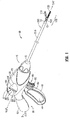
Fig. 1 is a front, perspective view of an endoscopic surgical forceps configured for use in accordance with the present disclosure; -
Fig. 2 is an enlarged, front, perspective view of an end effector assembly of the forceps ofFig. 1 , wherein jaw members of the end effector assembly are disposed in a spaced-apart position and wherein a monopolar assembly is disposed in a retracted position; -
Fig. 3 is an enlarged, rear, perspective view of the end effector assembly ofFig. 2 , wherein the jaw members are disposed in an approximated position and wherein the monopolar assembly is disposed in a deployed position; -
Fig. 4 is a side, perspective, cut-away view of the housing of the forceps ofFig. 1 showing the internal components disposed within the housing; -
Fig. 5 is an exploded, side view of a the internal working components of the forceps ofFig. 1 ; -
Fig. 6 is an exploded, side view of the lever assembly and trigger assembly of the forceps ofFig. 1 ; -
Fig. 7 is a side, interior view of a portion of the housing of the forceps ofFig. 1 ; -
Fig. 8A is a longitudinal, cross-sectional view of the end effector assembly ofFig. 2 with the jaw members disposed in a spaced-apart position; -
Fig. 8B is a longitudinal, cross-sectional view of the end effector assembly ofFig. 2 with the jaw members disposed in an approximated position; -
Fig. 8C is a longitudinal, cross-sectional view of the end effector assembly ofFig. 2 with the jaw members disposed in the approximated position and a knife disposed in an extended position; and -
Fig. 8D is a longitudinal, cross-sectional view of the end effector assembly ofFig. 2 with the knife disposed in the extended position and the monopolar assembly disposed in a deployed position. - Referring now to
Figs. 1-7 , a forceps provided in accordance with the present disclosure is shown generally identified byreference numeral 10.Forceps 10, as will be described below, is configured to operate in both a bipolar mode, e.g., for grasping, treating, and/or dissecting tissue, and a monopolar mode, e.g., for treating and/or dissecting tissue. Although the present disclosure is shown and described with respect toforceps 10, the aspects and features of the present disclosure are equally applicable for use with any suitable surgical instrument or portion(s) thereof for actuating, moving, and/or deploying the assemblies and/or components of the surgical instrument. Obviously, different connections and considerations apply to each particular instrument and the assemblies and/or components thereof; however, the aspects and features of the present disclosure remain generally consistent regardless of the particular instrument, assemblies, and/or components provided. - Continuing with reference to
Figs. 1-7 ,forceps 10 defines a longitudinal axis "X-X" and includes ahousing 20, ahandle assembly 30, atrigger assembly 60, a rotatingassembly 70, alever assembly 80, anend effector assembly 100, and amonopolar assembly 200.Forceps 10 further includes ashaft 12 having adistal end 14 configured to mechanically engageend effector assembly 100 and aproximal end 16 that mechanically engageshousing 20.Forceps 10 also includeselectrosurgical cable 2 that connectsforceps 10 to a generator (not shown) or other suitable power source, althoughforceps 10 may alternatively be configured as a battery powered instrument.Cable 2 includeswires 2a extending therethrough that have sufficient length to extend throughshaft 12 in order to provide electrical energy to at least one of the electrically-conductive plates jaw members end effector assembly 100, e.g., upon activation ofactivation switch 4 in a bipolar mode.Wires 2b ofcable 2, on the other hand, extend throughhousing 20 in order to provide electrical energy tomonopolar assembly 200, e.g., upon activation ofactivation switch 4 in a monopolar mode. Rotatingassembly 70 is rotatable in either direction about longitudinal axis "X-X" to rotateend effector 100 andmonopolar assembly 200 about longitudinal axis "X-X."Housing 20 houses the internal working components offorceps 10, which will be described in detail, in turn, below. - Referring to
Figs. 1-3 ,end effector assembly 100 is shown attached at adistal end 14 ofshaft 12 and includes a pair of opposingjaw members pivot 102. Each of thejaw members outer jaw housing conductive plate respective jaw housings flange Pivot 102 extends throughflanges couple jaw members plates wires 2a (Fig. 4 ), for conducting energy therebetween and through tissue grasped betweenjaw members end effector assembly 100 defines a bipolar configuration whereinplate 112 is charged to a first electrical potential andplate 122 is charged to a second, different electrical potential such that an electrical potential gradient is created for conducting energy betweenplates Fig. 1 ) is coupled towires 2a (Fig. 4 ), thus allowing the user to selectively apply energy toplates end effector assembly 100 during a bipolar mode of operation. -
End effector assembly 100 is designed as a unilateral assembly, i.e., wherejaw member 120 is fixed relative toshaft 12 andjaw member 110 is movable relative toshaft 12 and fixedjaw member 120. However,end effector assembly 100 may alternatively be configured as a bilateral assembly, i.e., where bothjaw member 110 andjaw member 120 are movable relative to one another and toshaft 12. In one some embodiments, aknife channel 115, 125 (Figs. 8A-8D ) may be defined within one or both ofjaw members knife 184 therethrough, e.g., upon actuation oftrigger 62 oftrigger assembly 60. - With reference to
Figs. 1 ,4 , and5 , handleassembly 30 includes amovable handle 40 and a fixedhandle 50. Fixedhandle 50 is integrally associated withhousing 20 andmovable handle 40 is movable relative to fixedhandle 50.Movable handle 40 is pivotably coupled tohousing 20 viapivot 41 and is pivotable aboutpivot 41 and relative to fixedhandle 50 between an initial position, whereinmovable handle 40 is spaced from fixedhandle 50, and a compressed position, whereinmovable handle 40 is compressed towards fixedhandle 50. A biasing member (not shown) may be provided to biasmovable handle 40 towards the initial position.Movable handle 40 is ultimately connected to adrive assembly 150 that, together, mechanically cooperate to impart movement of jaw members 110,120 between a spaced-apart position (Fig. 8A ) and an approximated position (Fig. 8B ) to grasp tissue between electrically-conductive plates jaw members Drive assembly 150 will be described in greater detail below. - Continuing with reference to
Figs. 1 ,4 , and5 , as mentioned above, drive assembly 150 interconnectsmovable handle 40 andend effector assembly 100.Movable handle 40 includes ahandle portion 43 defining afinger hole 44 and abifurcated arm 45 extending upwardly fromhandle portion 43 and intohousing 20.Arm 45 is bifurcated to define first and second spaced-apart flanges 46 that are pivotably coupled tohousing 20 at the free ends thereof viapivot 41. Flanges 46 extend on either side ofdrive assembly 150 and are coupled thereto to facilitate movement ofjaw members mandrel 152 and are disposed withinlateral slots 154 defined withinmandrel 152 such that pivoting ofmovable handle 40 aboutpivot 41 between the initial and compressed positions effects corresponding longitudinal translation ofmandrel 152. -
Mandrel 152 is fixedly engaged about the proximal end of anelongated drive member 156.Elongated drive member 156 extends distally fromhousing 20 and throughshaft 12, ultimately coupling to endeffector assembly 100. More specifically,elongated drive member 156 includes atransverse drive pin 158 disposed towards a distal end thereof that is pivotably disposed withinaperture 116 defined withinproximal flange 114 ofmovable jaw member 110, such that proximal translation ofelongated drive member 156 pullsjaw member 110 to pivot relative tojaw member 120 towards the approximated position, while distal translation ofelongated drive member 156 pushesjaw member 110 to pivot relative tojaw member 120 towards the spaced-apart position. As such, pivoting ofmovable handle 40 between the initial and compressed positions effects movement of drive member 156 (between a first, un-actuated position and a second, actuated position), to pivotjaw members -
Trigger assembly 60, as shown inFigs. 1 and4-6 , is coupled toknife assembly 180 such that trigger 62 is selectively actuatable from a first, un-actuated, distal position to a second, actuated, proximal position to advanceknife 184 from a retracted position (Fig. 8B ), whereinknife 184 is disposed proximally ofjaw members knife 184 extends betweenjaw members knife channels Fig. 8C ), to cut tissue grasped betweenjaw members Trigger assembly 60 will be described in greater detail below.Knife assembly 180 includes aknife drive rod 182 defining proximal anddistal ends Proximal end 183a ofknife drive rod 182 is coupled toconnector 68 oftrigger assembly 60 by abase member 188 that defines a pair of opposed,lateral protrusions 189.Knife drive rod 182 extends distally throughelongated drive member 156, which extends throughmandrel 152 andshaft 12, ultimately engaging the Proximal end ofknife 184,Knife 184 defines adistal cutting edge 186 configured to facilitate the cutting of tissue upon translation ofknife 184 therethrough. -
Trigger assembly 60 includes atrigger 62 having atoggle member 63 and abifurcated arm 66 extending upwardly fromtoggle member 63 and intohousing 20.Trigger 62 is pivotably coupled tohousing 20 viapivot 65, which extends through anintermediate portion 64 oftrigger 62.Arm 66 is bifurcated to define first and second spaced-apartflanges 67 to permit passage ofarm 66 aboutdrive assembly 150. Apin 69 pivotably couples flanges 67 oftrigger 62 toconnector 68.Connector 68 extends proximally throughhousing 20, ultimately coupling to the proximal end ofknife drive rod 182 ofknife assembly 180. Accordingly, upon pivoting oftrigger 62 aboutpivot pin 65 and relative tohousing 20 from the un-actuated position towards the actuated position, flanges 67 are rotated to pullconnector 68 distally such thatknife drive rod 182 is pushed distally (from a first, un-actuated position to a second, actuated position) to translateknife 184 from the retracted position towards the extended position. On the other hand, upon return oftrigger 62 towards the un-actuated position, flanges 67 are rotated to pushconnector 68 proximally such thatknife drive rod 182 is pulled proximally (from the second, actuated position back to the first, un-actuated position) to translateknife 184 back towards the retracted position. A biasingmember 140, e.g., a coil spring, is coupled to pin 69 at adistal end 142 thereof and to alinkage assembly 300, which will be described in greater detail below, at aproximal end 144 thereof for biasingtrigger 62 towards the un-actuated position, thereby biasingknife 184 towards the retracted position. Further, with additional reference toFig. 7 ,housing 20 may define a pair oflongitudinal tracks 21 on opposing sides thereof (only one is shown) that are configured to receive opposed,lateral protrusions 189 ofbase member 188 ofknife drive rod 182 to guide translation ofknife drive rod 182 and, thus,knife 184 between the retracted and extended positions. - Referring to
Figs. 1 and4-6 ,lever assembly 80 is shown. Althoughlever assembly 80 is shown disposed on only one side ofhousing 20,lever assembly 80 may be configured to define a symmetrical configuration having substantially similar components disposed on either side ofhousing 20, thus allowing actuation oflever assembly 80 from either side ofhousing 20. However, for purposes of simplicity, only one side oflever assembly 80 will be described herein. -
Lever assembly 80 is disposed within arecess 24 defined on an exterior side surface of housing 20 (althoughlever assembly 80 may also be positioned at any other suitable location) and includes alever 82 that is rotatable about apivot 84 between a proximal position, whereinfree end 86 oflever 82 is disposed at aproximal end 25 ofrecess 24, and a distal position, whereinfree end 86 oflever 82 is disposed at adistal end 26 ofrecess 24. In configurations wherelever assembly 80 defines a symmetrical configuration, a pair oflevers 82 are provided on either side ofhousing 20, each of which is coupled to one end ofpivot 84.Pivot 84 is rotatably coupled tohousing 20 and extends throughhousing 20. A pair ofarms 90 disposed withinhousing 20 on opposed sides thereof are coupled to pivot 84 and extend therefrom. More specifically, eacharm 90 is engaged aboutpivot 84 oflever assembly 80 at thefirst end 92 thereof such that rotation ofpivot 84 relative tohousing 20, e.g., via rotation oflever 82, effects rotation of second ends 94 ofarms 90 about first ends 92 thereof. Eacharm 90 further includes aslot 96 defined therethrough towardssecond end 94 thereof.Slots 96 are configured to slidably receivetransverse pin 204 ofhub 203 ofdrive shaft 202 ofmonopolar assembly 200 therein such that, upon rotation ofarms 90 aboutpivot 84, e.g., upon actuation oflever 82, the angular displacement ofarms 90 is converted into longitudinal translation ofhub 203 and, thus, longitudinal translation ofdrive shaft 202 of monopolar assembly 200 (from a first, un-actuated position, to a second, actuated position) to move insulativesleeve 210 andenergizable rod member 220 ofmonopolar assembly 200 from the retracted position (Figs. 2 and8C ) to the deployed position (Figs. 3 and8D ), as will be described in greater detail below. - With reference to
Figs. 1-7 ,monopolar assembly 200 includes adrive shaft 202, aferrule 208, aninsulative sleeve 210, and anenergizable rod member 220. Driveshaft 202 includes ahub 203 disposed at the proximal end thereof.Hub 203 includes a having atransverse pin 204 extending outwardly therefrom.Transverse pin 204, as mentioned above, is configured for slidable receipt withinslots 96 ofarms 90 oflever assembly 80 such that pivotal movement oflever 82 effects longitudinal translation oftransverse pin 204 and, thus, driveshaft 202. Opposed ends oftransverse pin 204 are configured for slidable receipt withinlongitudinal tracks 21 of housing 20 (seeFig. 7 ) to guide longitudinal translation ofdrive shaft 202 and, thus,monopolar assembly 200 between the retracted position (Figs. 2 and8C ) and the deployed position (Figs. 3 and8D ). - Drive
shaft 202 is slidably disposed withinknife drive rod 182 andelongated drive member 156 and is coupled toferrule 208 towards the distal end thereof. More specifically,knife drive rod 182 andelongated drive member 156 each define alongitudinal slot ferrule 208, which is disposed aboutshaft 12, to driveshaft 202 ofmonopolar assembly 200 via one ormore pins 209, although other suitable engagements may also be provided.Ferrule 208 engagesinsulative sleeve 210 andenergizable rod member 220 to driveshaft 202 such that longitudinal translation ofdrive shaft 202 effects corresponding longitudinal translation ofinsulative sleeve 210 andenergizable rod member 220. Accordingly, actuation oflever 82 may be effected to translatedrive shaft 202 distally, thereby movinginsulative sleeve 210 andenergizable rod member 220 from the retracted position (Figs. 2 and8C ) to the deployed position (Figs. 3 and8D ). -
Insulative sleeve 210 is slidably disposed aboutshaft 12 and is configured for translation about and relative toshaft 12 between a retracted position (Figs. 2 and8C ), whereinsulative sleeve 210 is disposed proximally ofend effector assembly 100, and a deployed position (Figs. 3 and8D ), whereininsulative sleeve 210 is substantially disposed aboutend effector 100 so as to electrically insulateplates jaw members insulative sleeve 210.Energizable rod member 220 extends throughsleeve 210 and distally therefrom, ultimately defining an electrically-conductivedistal tip 224. Distal tip 226 may be hook-shaped (as shown), or may define any other suitable configuration, e.g., linear, circular, angled, etc.Energizable rod member 220 and, more specifically,distal tip 224 thereof, function as the active electrode ofmonopolar assembly 200.Sleeve 210 androd member 220 may be fixedly engaged to one another and/orferrule 208 such thatsleeve 210 androd member 220 move in concert with one another between their retracted position (Figs. 2 and8C ) and the deployed position (Fig. 8D ), e.g., upon actuation of lever 82 (Fig. 1 ), although other configurations may also be provided.Wires 2b, which extend fromelectrosurgical cable 2 throughhousing 20, are coupled toenergizable rod member 220 to provide energy toenergizable rod member 220, e.g., upon actuation of activation switch 4 (Fig. 1 ) in a monopolar mode, for treating tissue in a monopolar mode of operation. - In the retracted position, as shown in
Figs. 2 and8C ,distal tip 224 ofmonopolar assembly 200 is disposed within an insulatingmember 126, e.g., an insulated recess defined withinproximal flange 124 ofjaw member 120, although other configurations are also contemplated. Insulatingmember 126 is electrically-insulated such thatdistal tip 224 ofrod member 220 is isolated from electrically-conductive plates jaw members distal tip 224 ofrod member 220 may only be insulated fromplate 112. In such configurations,distal tip 224 ofrod member 220 is capable of being energized to the same polarity asplate 122. In the extended position, as shown inFigs. 3 and8D ,distal tip 224 ofrod member 220 extends distally fromend effector assembly 100 andinsulative sleeve 210, which substantially surroundsend effector assembly 100. In this position, energy may be applied todistal tip 224 ofrod member 220 to treat tissue, e.g., via activation of activation switch 4 (Fig. 1 ) in the monopolar mode. - With reference to
Figs. 4 and6 , in conjunction withFigs. 1-3 ,5 , and7 , a portion ofdistal surfaces 99 ofarms 90 abut the proximal end ofconnector 68 oftrigger assembly 60 whentrigger 62 is disposed in the un-actuated position, e.g., whenknife 184 is disposed in the retracted position. As such, upon actuation oflever 82 to rotatearms 90 aboutpivot 84 in the distal direction to thereby translatemonopolar assembly 200 to the deployed position,distal surfaces 99 ofarms 90urge connector 68 distally. Distal urging ofconnector 68, as mentioned above, translatesknife 184 from the retracted position towards the extended position. This configuration, whereinarms 90abut connector 68 such thatknife 184 is translated to the extended position upon movement ofmonopolar assembly 200 to the deployed position is advantageous in that it allows these components to assume a more compact configuration, freeing up space withinhousing 20 for other components and/or allowing for a morecompact housing 20 to be used. However, urgingconnector 68 distally to translateknife 184 from the retracted position towards the extended position upon deployment ofmonopolar assembly 200 requires thatlever 82 be actuated with sufficient force so as to overcome the biasing force of biasingmember 140, which, as described above, biases triggerassembly 60 and, thus,connector 68 proximally. - In order to reduce the force required to actuate
lever 82 while still providing the space-conserving benefits described above, alinkage assembly 300 is operably coupled between biasingmember 140 oftrigger assembly 60 andarms 90 oflever assembly 80. However, the presently disclosedlinkage assembly 300 is not limited to this particular use, aslinkage assembly 300 may alternatively be used with any suitable components and/or assemblies of a surgical instrument. -
Linkage assembly 300 includes a pair of spaced-apartlinkage members 310, each of which defines afirst end 312 and asecond end 314. Afirst pin 316 extends between and outwardly fromlinkage members 310 at the first ends 312 thereof.Proximal end 144 of biasingmember 140 is coupled to the portion offirst pin 316 that extends betweenlinkage members 310, while the outwardly-extending portions offirst pin 316 are configured for slidable receipt within linkage tracks 27 defined withinhousing 20, as will be described in greater detail below. Asecond pin 318 extends betweenlinkage members 310 at the second ends 314 thereof for pivotablycoupling linkage members 310 toarms 90 oflever assembly 80. As such, and as will be described in greater detail below, although the distal advancement ofconnector 68, which is effected by actuation oflever 82 to translatemonopolar assembly 200 to the deployed position, pullsdistal end 142 of biasingmember 140 distally, actuation oflever 82 also moveslinkage members 310 and, thus,proximal end 144 of biasingmember 140 distally, such that the tension on biasingmember 140 is reduced (or removed) and a reduced biasing force (or no biasing force) from biasingmember 140 is imparted to lever 82, despite the fact thatknife assembly 180 is being advanced towards the extended position. - With reference to
Fig. 7 , in conjunction withFigs. 4-6 , as mentioned above,housing 20 includes a pair of longitudinal tracks 21 (only one is shown) defined on either side thereof, and a pair of linkage tracks 27 (only one is shown) defined on either side thereof. Eachlongitudinal track 21, as mentioned above, is configured to guide translation oflateral protrusions 189 ofbase member 188 ofconnector 68 andtransverse pin 204 ofhub 203 ofdrive shaft 202 therealong so as to guide translation ofknife assembly 180 andmonopolar assembly 200, respectively, along substantially longitudinal paths. The proximal and distal ends oflongitudinal tracks 21 may also be configured to define the retracted and extended positions ofknife 184 and/or the retracted and deployed positions ofmonopolar assembly 200, since translation oflateral protrusions 189 andtransverse pin 204 throughlongitudinal tracks 21 is limited at least by the length oflongitudinal tracks 21, e.g., the proximal and distal ends thereof. - Each
linkage track 27 defined withinhousing 20 is configured to guide translation offirst pin 316 oflinkage members 310 throughhousing 20 and to provide a safety lockout feature that inhibits accidental actuation ofmonopolar assembly 200. More specifically, linkage tracks 27 each include a first, generallylongitudinal portion 28 and asecond portion 29 that angles downwardly and distally from the proximal end offirst portion 28. Thus, as will be described in greater detail below, withfirst pin 316 disposed at the bases ofsecond portions 29 of linkage tracks 27 and biased distally via biasingmember 140,linkage members 310 are maintained in position and, thus,monopolar assembly 200 is locked in the retracted position. In this position,proximal end 144 of biasingmember 140 is substantially fixed in position such that biasingmember 140 may function to biastrigger assembly 60 towards the un-actuated position, thereby biasingknife 184 towards the retracted position. Once removed fromsecond portions 29 of linkage tracks 27,first pin 316 is permitted to translate alongfirst portions 28 of linkage tracks 27 such that the tension on biasingmember 140 remains substantially unchanged during actuation ofmonopolar assembly 200, thereby substantially removing the biasing force of biasingmember 140 from application during actuation oflever assembly 80. - Turning now to
Figs. 8A-8D , in conjunction withFigs. 1-7 , the use and operation offorceps 10 in both the bipolar mode, e.g., for grasping, treating and/or cutting tissue, and the monopolar mode, e.g., for electrical/electromechanical tissue treatment, is described. Initially, with respect to the bipolar mode, as shown inFig. 8A ,jaw members monopolar assembly 200 remains disposed in the retracted position, as shown inFigs. 8A-8C , whereininsulative sleeve 210 is positioned proximally ofjaw members energizable rod member 220 is disposed in the retracted position withininsulative member 126 ofjaw member 120. At this point,trigger assembly 60 is disposed in the un-actuated position such thatknife 184 is disposed in the retracted position, lever 82 oflever assembly 80 is disposed at theproximal end 25 ofrecess 24 such thatmonopolar assembly 200 is disposed in the retracted position, andfirst pin 316 is disposed withinsecond portions 29 of linkage tracks 27. - With
jaw members end effector assembly 100 may be maneuvered into position such that tissue to be grasped, treated, e.g., sealed, and/or cut, is disposed betweenjaw members movable handle 40 is depressed, or pulled proximally relative to fixedhandle 50 such thatjaw member 110 is pivoted relative tojaw member 120 from the spaced-apart position to the approximated position to grasp tissue therebetween, as shown inFig. 8B . In this approximated position, energy may be supplied, e.g., via activation ofswitch 4, to plate 112 ofjaw member 110 and/orplate 122 ofjaw member 120 and conducted through tissue to treat tissue, e.g., to effect a tissue seal or otherwise treat tissue in the bipolar mode of operation. - Once tissue treatment is complete (or to cut untreated tissue),
knife 184 ofknife assembly 180 may be deployed from withinshaft 12 to betweenjaw members trigger 62 oftrigger assembly 60, to cut tissue grasped therebetween. More specifically, upon actuation oftrigger 62,knife 184 is advanced distally fromshaft 12 to extend at least partially throughknife channels jaw members jaw members 110, 120 (Fig. 8C ). Upon actuation oftrigger 62,protrusions 189 ofknife drive bar 182 are translated alonglongitudinal tracks 21 ofhousing 20 to guide translation ofknife 184 to the extended position. Further, at this point,first pin 316 remains disposed withinsecond portions 29 of linkage tracks 27. As such,proximal end 144 of biasingmember 140 remains fixed in position whiledistal end 142 of biasingmember 142 is advanced distally upon actuation oftrigger 62. During actuation oftrigger 62,first pin 316 is biased further towards the base ofsecond portions 29 of linkage tracks 27 via biasingmember 142, thus lockingmonopolar assembly 200 in position and inhibiting accidental deployment of monopolar assembly. - When tissue cutting is complete, trigger 62 may be released to allow
connector 68 andknife drive rod 182 to return proximally under the bias of biasingmember 142 such thatknife 184 is returned to the retracted position withinshaft 12. Next,jaw members Fig. 8A ) to release the treated and/or divided tissue. - For operation of
forceps 10 in the monopolar mode,movable handle 40 is first depressed relative to fixedhandle 50 to pivotjaw member 110 relative tojaw member 120 from the spaced-apart position to the approximated position. Withjaw members monopolar assembly 200 may be translated from the retracted position (Fig. 8C ) to the deployed position (Fig. 8D ) via actuation oflever assembly 80. More specifically, in order to translateinsulative sleeve 210 andenergizable rod member 220 ofmonopolar assembly 200 from the retracted position (Fig. 8C ) to the deployed position (Fig. 8D ),lever 82 is rotated throughrecess 24 ofhousing 20 from theproximal end 25 thereof to thedistal end 26 thereof. Rotation oflever 82 in this manner rotatesarms 90 similarly to urgepin 204 ofhub 203 ofdrive shaft 202 distally such thatinsulative sleeve 210 is translated distally to the deployed position, whereininsulative sleeve 210 surroundsjaw members 110, 120 (Fig. 8D ) andenergizable rod member 220 is likewise translated distally to the deployed position, whereinenergizable rod member 220 extends distally from end effector assembly 100 (Fig. 8D ). - At the same time as
monopolar assembly 200 is advanced distally,arms 90urge connector 68 distally such thatpin 69 is advanced distally and such thatknife 184 is translated from the extended position towards the retracted position. However, rotation ofarms 90 also effects distal advancement oflinkage members 310, asfirst pin 316 is moved alonglinkage slots 27 from thesecond portion 29 thereof to thefirst portion 28 thereof. Oncefirst pin 316 reachesfirst portion 28 oflinkage slots 27 and is thus permitted to translate distally therealong,linkage members 310 are permitted to move distally to urgeproximal end 144 of biasingmember 140 distally a substantially equal distance as the distal translation ofdistal end 142 of biasingmember 140, which is engaged to pin 69. As such, with a reduced (or removed) tension on biasingmember 140, a reduced biasing force (or no biasing force) from biasingmember 140 is felt upon actuation oflever 82. - Once
monopolar assembly 200 is disposed in the deployed position,activation switch 4 may be actuated to supply energy toenergizable rod member 220 to treat, e.g., dissect, tissue. During application of energy to tissue viaenergizable rod member 220,forceps 10 may be moved relative to tissue, e.g., longitudinally along longitudinal axis "X-X" and/or radially therefrom, to facilitate electromechanical treatment of tissue. At the completion of tissue treatment, e.g., dissection,monopolar assembly 200 may be returned to the retracted position (Fig. 8C ) via rotatinglever 82 from thedistal end 26 ofrecess 24 back to theproximal end 25 thereof. Rotation oflever 82 from the second position back to the first position rotatesarms 90 back to their initial position such thatlinkage members 310,trigger assembly 60, andknife assembly 180 are likewise returned to their respective initial positions. - From the foregoing and with reference to the various figure drawings, those skilled in the art will appreciate that certain modifications can also be made to the present disclosure without departing from the scope of the same. While several embodiments of the disclosure have been shown in the drawings, it is not intended that the disclosure be limited thereto, as it is intended that the disclosure be as broad in scope as the art will allow and that the specification be read likewise. Therefore, the above description should not be construed as limiting, but merely as exemplifications of particular embodiments. Those skilled in the art will envision other modifications within the scope and spirit of the claims appended hereto.
- The invention may be described by reference to the following numbered paragraphs:-
- 1. A surgical instrument, comprising:
- an end effector assembly including first and second jaw members, at least one of the jaw members movable relative to the other between a spaced- apart position and an approximated position for grasping tissue therebetween;
- a knife selectively movable relative to the jaw members between a retracted position and an extended position, wherein the knife extends at least partially between the jaw members to cut tissue grasped therebetween;
- a trigger assembly coupled to the knife and selectively movable from an un-actuated position to an actuated position to move the knife from the retracted position to the extended position;
- a biasing member coupled to the trigger assembly and configured to apply a biasing force to the trigger assembly to bias the trigger assembly towards the un-actuated position;
- a monopolar assembly including an energizable member, the monopolar assembly selectively movable relative to the jaw members between a stored position and a use position, wherein the energizable member extends distally from the jaw members;
- a lever assembly coupled to the monopolar assembly and selectively movable from a first position to a second position to move the monopolar assembly from the stored position to the use position, the lever assembly coupled to the trigger assembly such that movement of the lever assembly from the first position to the second position effects movement of the trigger assembly from the un-actuated position towards the actuated position; and
- a linkage assembly coupled to the lever assembly and the biasing member, the linkage assembly configured to reduce the biasing force applied to the trigger assembly when the lever assembly effects movement of the trigger assembly from the un-actuated position towards the actuated position.
- 2. The surgical instrument according to paragraph 1, wherein the monopolar assembly further includes an insulative sleeve, and wherein, upon movement of the monopolar assembly from the stored position to the use position, the insulative sleeve is moved from a proximal position to a distal position, wherein the insulative sleeve is disposed about the jaw members.
- 3. The surgical instrument according to paragraph 1, wherein at least a portion of the lever assembly is configured to contact at least a portion of the trigger assembly upon actuation of the lever assembly to urge the trigger assembly from the un-actuated position towards the actuated position.
- 4. The surgical instrument according to paragraph 1, wherein the trigger assembly and lever assembly are at least partially disposed within a housing configured to guide movement of at least one of the trigger assembly and lever assembly.
- 5. A surgical instrument, comprising:
- a first actuation assembly coupled to a first component and selectively movable from a first position to a second position to actuate the first component;
- a biasing member coupled to the first actuation assembly and configured to apply a biasing force to the first actuation assembly to bias the first actuation assembly towards the first position;
- a second actuation assembly coupled to a second component and selectively actuatable to actuate the second component, the second actuation assembly coupled to the first actuation assembly such that actuation of the second actuation assembly effects movement of the first actuating assembly from the first position towards the second position; and
- a linkage assembly coupled to the second actuation assembly and the biasing member, the linkage assembly configured to reduce the biasing force applied to the first actuation assembly when the second actuation assembly effects movement of the first actuation assembly from the first position towards the second position.
- 6. The surgical instrument according to paragraph 5, wherein at least a portion of the second actuation assembly is configured to contact at least a portion of the first actuation assembly upon actuation of the second actuation assembly to urge the first actuation assembly from the first position towards the second position.
- 7. The surgical instrument according to paragraph 5, wherein the first actuation assembly includes a trigger pivotably coupled thereto and selectively movable from an un actuated position to an actuated position for moving the first actuation assembly from the first position to the second position.
- 8. The surgical instrument according to paragraph 5, wherein the second actuation assembly includes a lever pivotable from a proximal position to a distal position for actuating the second actuation assembly.
- 9. The surgical instrument according to paragraph 5, wherein the first and second actuation assemblies are at least partially disposed within a housing.
- 10. The surgical instrument according to paragraph 9, wherein the housing defines at least one track configured to guide movement of at least one of the first actuation assembly between the first and second positions and actuation of the second actuation assembly.
- 11. The surgical instrument according to paragraph 5, wherein the biasing member is coupled to the first actuation assembly at a first end thereof and to the linkage assembly at a second end thereof.
- 12. The surgical instrument according to paragraph 11, wherein the first actuation assembly is configured to move the first end of the biasing member distally upon movement of the first actuation assembly from the first position towards the second position.
- 13. The surgical instrument according to
paragraph 12, wherein the linkage is configured to maintain the second end of the biasing member in substantially fixed position when the second actuation assembly is un-actuated. - 14. The surgical instrument according to
paragraph 12, wherein the linkage is configured to move the second end of the biasing member distally upon actuation of the second actuation assembly. - 15. The surgical instrument according to
paragraph 14, wherein the linkage is configured to move the second end of the biasing member distally a distance that is substantially equal to a distance the first actuation assembly is configured to move the first end of the biasing member distally upon movement of the first actuation assembly from the first position towards the second position. - 16. A method of actuating components of a surgical instrument, comprising the steps of:
- moving a first actuation assembly against a biasing force from a first position to a second position to actuate a first component;
- returning the first actuation assembly from the second position back to the first position; and
- moving a second actuation assembly to actuate a second component, wherein moving the second actuation assembly effects movement of the first actuation assembly from the first position to the second position under a reduced biasing force.
- 17. The method according to
paragraph 16, wherein a trigger is moved from an un-actuated position to an actuated position to move the first actuation assembly from the first position to the second position. - 18. The method according to
paragraph 16, wherein a lever is moved from a proximal position to a distal position to move the second actuation assembly. - 19. The method according to
paragraph 16, wherein a biasing member applies the biasing force to bias the first actuation assembly towards the first position. - 20. The method according to
paragraph 16, wherein the first actuation assembly is returned from the second position to the first position under the biasing force.
Claims (11)
- A surgical instrument, comprising:a housing defining a track including a longitudinal portion and an angled portion extending from the longitudinal portion;a first actuation assembly selectively actuatable to deploy a first component;a biasing member coupled at a first end thereof to the first actuation assembly;a pin coupled to a second end of the biasing member and slidably disposed within the track; anda second actuation assembly selectively actuatable to deploy a second component, the second actuation assembly coupled to the first actuation assembly such that actuation of the second actuation assembly also actuates the first actuation assembly,wherein the pin is maintained within the angled portion of the track when the first actuation assembly is actuated such that the biasing member applies a biasing force against actuation of the first actuation assembly, andwherein the pin is moved to the longitudinal portion of the track and slid therealong when the second actuation assembly is actuated such that the biasing member applies a reduced biasing force against actuation of the second actuation assembly.
- The surgical instrument according to claim 1, wherein at least a portion of the second actuation assembly is configured to contact at least a portion of the first actuation assembly upon actuation of the second actuation assembly to thereby actuate the first actuation assembly.
- The surgical instrument according to claim 1 or claim 2, wherein the first actuation assembly includes a first actuator pivotable from an un-actuated position to an actuated position to actuate the first actuation assembly.
- The surgical instrument according to claims 1, 2 or 3, wherein the second actuation assembly includes a second actuator pivotable from an un-actuated position to an actuated position to actuate the first and second actuation assemblies.
- The surgical instrument according to any preceding claim, wherein the first and second actuation assemblies are at least partially disposed within the housing.
- The surgical instrument according to any preceding claim , wherein the track is defined on opposing inner surfaces of the housing.
- The surgical instrument according to any preceding claim, further comprising a linkage assembly coupled to the second actuation assembly and the pin, the linkage assembly configured to urge the pin from the angled portion of the track to the longitudinal portion of the track upon actuation of the second actuation assembly.
- The surgical instrument according to any preceding claim, wherein, upon actuation of the first actuation assembly, the first end of the biasing member is moved away from the second end of the biasing member.
- The surgical instrument according to claim 8, wherein, upon actuation of the first actuation assembly with the second actuation assembly remaining un-actuated, the second end of the biasing member is maintained in substantially fixed position within the angled portion of the track.
- The surgical instrument according to claim 8, wherein, upon actuation of the second actuation assembly, the pin is moved to and along the longitudinal portion of the track towards the first end of the biasing member, thereby moving the second end of the biasing member towards the first end of the biasing member.
- The surgical instrument according to claim 10, wherein, upon actuation of the second actuation assembly, the second end of the biasing member is moved along the longitudinal portion of the track a distance that is substantially equal to a distance the first end of the biasing member is moved away from the second end of the biasing member.
Applications Claiming Priority (4)
| Application Number | Priority Date | Filing Date | Title |
|---|---|---|---|
| US201261726980P | 2012-11-15 | 2012-11-15 | |
| US14/052,871 US10772674B2 (en) | 2012-11-15 | 2013-10-14 | Deployment mechanisms for surgical instruments |
| EP13855800.2A EP2919693B1 (en) | 2012-11-15 | 2013-10-18 | Deployment mechanisms for surgical instruments |
| PCT/US2013/065659 WO2014078012A1 (en) | 2012-11-15 | 2013-10-18 | Deployment mechanisms for surgical instruments |
Related Parent Applications (2)
| Application Number | Title | Priority Date | Filing Date |
|---|---|---|---|
| EP13855800.2A Division EP2919693B1 (en) | 2012-11-15 | 2013-10-18 | Deployment mechanisms for surgical instruments |
| EP13855800.2A Division-Into EP2919693B1 (en) | 2012-11-15 | 2013-10-18 | Deployment mechanisms for surgical instruments |
Publications (2)
| Publication Number | Publication Date |
|---|---|
| EP3207894A1 true EP3207894A1 (en) | 2017-08-23 |
| EP3207894B1 EP3207894B1 (en) | 2018-12-12 |
Family
ID=50682405
Family Applications (2)
| Application Number | Title | Priority Date | Filing Date |
|---|---|---|---|
| EP17157081.5A Active EP3207894B1 (en) | 2012-11-15 | 2013-10-18 | Deployment mechanisms for surgical instruments |
| EP13855800.2A Active EP2919693B1 (en) | 2012-11-15 | 2013-10-18 | Deployment mechanisms for surgical instruments |
Family Applications After (1)
| Application Number | Title | Priority Date | Filing Date |
|---|---|---|---|
| EP13855800.2A Active EP2919693B1 (en) | 2012-11-15 | 2013-10-18 | Deployment mechanisms for surgical instruments |
Country Status (3)
| Country | Link |
|---|---|
| US (2) | US10772674B2 (en) |
| EP (2) | EP3207894B1 (en) |
| WO (1) | WO2014078012A1 (en) |
Cited By (1)
| Publication number | Priority date | Publication date | Assignee | Title |
|---|---|---|---|---|
| WO2020201904A1 (en) * | 2019-04-04 | 2020-10-08 | Ethicon Llc | Monopolar and bipolar functionality |
Families Citing this family (22)
| Publication number | Priority date | Publication date | Assignee | Title |
|---|---|---|---|---|
| US7628791B2 (en) | 2005-08-19 | 2009-12-08 | Covidien Ag | Single action tissue sealer |
| US10070916B2 (en) | 2013-03-11 | 2018-09-11 | Covidien Lp | Surgical instrument with system and method for springing open jaw members |
| US9456863B2 (en) | 2013-03-11 | 2016-10-04 | Covidien Lp | Surgical instrument with switch activation control |
| US9655673B2 (en) | 2013-03-11 | 2017-05-23 | Covidien Lp | Surgical instrument |
| US10231776B2 (en) | 2014-01-29 | 2019-03-19 | Covidien Lp | Tissue sealing instrument with tissue-dissecting electrode |
| US10660694B2 (en) | 2014-08-27 | 2020-05-26 | Covidien Lp | Vessel sealing instrument and switch assemblies thereof |
| US10039593B2 (en) | 2014-09-17 | 2018-08-07 | Covidien Lp | Surgical instrument having a bipolar end effector assembly and a deployable monopolar assembly |
| US9918785B2 (en) | 2014-09-17 | 2018-03-20 | Covidien Lp | Deployment mechanisms for surgical instruments |
| US9987076B2 (en) * | 2014-09-17 | 2018-06-05 | Covidien Lp | Multi-function surgical instruments |
| US10039592B2 (en) | 2014-09-17 | 2018-08-07 | Covidien Lp | Deployment mechanisms for surgical instruments |
| US9687294B2 (en) * | 2014-11-17 | 2017-06-27 | Covidien Lp | Deployment mechanism for surgical instruments |
| US9724153B2 (en) | 2014-11-17 | 2017-08-08 | Covidien Lp | Deployment mechanisms for surgical instruments |
| US10478245B2 (en) * | 2014-12-10 | 2019-11-19 | Covidien Lp | Energizable attachment for surgical devices |
| USD844139S1 (en) | 2015-07-17 | 2019-03-26 | Covidien Lp | Monopolar assembly of a multi-function surgical instrument |
| USD844138S1 (en) | 2015-07-17 | 2019-03-26 | Covidien Lp | Handle assembly of a multi-function surgical instrument |
| AU2018230445B2 (en) * | 2017-03-10 | 2023-10-12 | Boston Scientific Scimed, Inc. | Actuator devices and systems |
| US11179190B2 (en) * | 2017-12-12 | 2021-11-23 | Gyrus Acmi, Inc. | Laparoscopic forceps assembly with an operable mechanism |
| US10828756B2 (en) | 2018-04-24 | 2020-11-10 | Covidien Lp | Disassembly methods facilitating reprocessing of multi-function surgical instruments |
| US10993721B2 (en) * | 2018-04-25 | 2021-05-04 | Covidien Lp | Surgical clip applier |
| US20200405380A1 (en) * | 2019-06-27 | 2020-12-31 | Covidien Lp | Multi-function surgical instruments |
| US11806068B2 (en) | 2020-12-15 | 2023-11-07 | Covidien Lp | Energy-based surgical instrument for grasping, treating, and/or dividing tissue |
| US20220183745A1 (en) * | 2020-12-15 | 2022-06-16 | Covidien Lp | Energy-based surgical instrument for grasping, treating, and/or dividing tissue |
Citations (3)
| Publication number | Priority date | Publication date | Assignee | Title |
|---|---|---|---|---|
| US20050113827A1 (en) * | 2003-11-17 | 2005-05-26 | Dumbauld Patrick L. | Bipolar forceps having monopolar extension |
| EP1769765A1 (en) * | 2005-09-30 | 2007-04-04 | Sherwood Services AG | Insulating boot for electrosurgical forceps |
| US20070106297A1 (en) * | 2005-09-30 | 2007-05-10 | Dumbauld Patrick L | In-line vessel sealer and divider |
Family Cites Families (229)
| Publication number | Priority date | Publication date | Assignee | Title |
|---|---|---|---|---|
| SU401367A1 (en) | 1971-10-05 | 1973-10-12 | Тернопольский государственный медицинский институт | BIAKTIVNYE ELECTRO SURGICAL INSTRUMENT |
| DE2415263A1 (en) | 1974-03-29 | 1975-10-02 | Aesculap Werke Ag | Surgical H.F. coagulation probe has electrode tongs - with exposed ends of insulated conductors forming tong-jaws |
| DE2514501A1 (en) | 1975-04-03 | 1976-10-21 | Karl Storz | Bipolar coagulation instrument for endoscopes - has two high frequency electrodes looped over central insulating piece |
| US4005714A (en) | 1975-05-03 | 1977-02-01 | Richard Wolf Gmbh | Bipolar coagulation forceps |
| FR2315286A2 (en) | 1975-06-26 | 1977-01-21 | Lamidey Marcel | H.F. blood coagulating dissecting forceps - with adjustable stops to vary clamping space and circuit making contacts |
| USD249549S (en) | 1976-10-22 | 1978-09-19 | Aspen Laboratories, Inc. | Electrosurgical handle |
| USD263020S (en) | 1980-01-22 | 1982-02-16 | Rau Iii David M | Retractable knife |
| JPS6030945A (en) | 1983-08-01 | 1985-02-16 | Mitsubishi Electric Corp | Hot-water storage type hot-water supply device |
| DE3490633T (en) | 1984-01-30 | 1985-12-12 | Char'kovskaja oblastnaja kliničeskaja bol'nica, Char'kov | Bipolar electrosurgical device |
| DE3423356C2 (en) | 1984-06-25 | 1986-06-26 | Berchtold Medizin-Elektronik GmbH & Co, 7200 Tuttlingen | Electrosurgical high frequency cutting instrument |
| US4657016A (en) | 1984-08-20 | 1987-04-14 | Garito Jon C | Electrosurgical handpiece for blades, needles and forceps |
| USD299413S (en) | 1985-07-17 | 1989-01-17 | The Stanley Works | Folding pocket saw handle |
| USD295893S (en) | 1985-09-25 | 1988-05-24 | Acme United Corporation | Disposable surgical clamp |
| USD295894S (en) | 1985-09-26 | 1988-05-24 | Acme United Corporation | Disposable surgical scissors |
| USD298353S (en) | 1986-05-06 | 1988-11-01 | Vitalmetrics, Inc. | Handle for surgical instrument |
| JPH0540112Y2 (en) | 1987-03-03 | 1993-10-12 | ||
| JPS6424051A (en) | 1987-07-16 | 1989-01-26 | Meisho Koki Kk | Sheet glass having transparency pattern and its production |
| DE8712328U1 (en) | 1987-09-11 | 1988-02-18 | Jakoubek, Franz, 7201 Emmingen-Liptingen, De | |
| JPH01147150A (en) | 1987-12-04 | 1989-06-08 | Hitachi Ltd | Variable venturi carburetor |
| US5026379A (en) | 1989-12-05 | 1991-06-25 | Inbae Yoon | Multi-functional instruments and stretchable ligating and occluding devices |
| JP2806511B2 (en) | 1990-07-31 | 1998-09-30 | 松下電工株式会社 | Manufacturing method of sintered alloy |
| US5389102A (en) | 1990-09-13 | 1995-02-14 | United States Surgical Corporation | Apparatus and method for subcuticular stapling of body tissue |
| US5190541A (en) | 1990-10-17 | 1993-03-02 | Boston Scientific Corporation | Surgical instrument and method |
| JP2951418B2 (en) | 1991-02-08 | 1999-09-20 | トキコ株式会社 | Sample liquid component analyzer |
| US5330471A (en) | 1991-06-07 | 1994-07-19 | Hemostatic Surgery Corporation | Bi-polar electrosurgical endoscopic instruments and methods of use |
| USD348930S (en) | 1991-10-11 | 1994-07-19 | Ethicon, Inc. | Endoscopic stapler |
| JPH0630945B2 (en) | 1991-12-20 | 1994-04-27 | 株式会社サトー | Winding mechanism to prevent meandering of carbon ribbon |
| US5620459A (en) | 1992-04-15 | 1997-04-15 | Microsurge, Inc. | Surgical instrument |
| JPH0630945A (en) | 1992-05-19 | 1994-02-08 | Olympus Optical Co Ltd | Suturing apparatus |
| USD349341S (en) | 1992-10-28 | 1994-08-02 | Microsurge, Inc. | Endoscopic grasper |
| DE4242143C2 (en) | 1992-12-14 | 2001-04-12 | Delma Elektro Med App | High frequency surgical hand instrument |
| US5342359A (en) | 1993-02-05 | 1994-08-30 | Everest Medical Corporation | Bipolar coagulation device |
| DE4303882C2 (en) | 1993-02-10 | 1995-02-09 | Kernforschungsz Karlsruhe | Combination instrument for separation and coagulation for minimally invasive surgery |
| JP3390041B2 (en) | 1993-04-05 | 2003-03-24 | オリンパス光学工業株式会社 | Forceps |
| GB9309142D0 (en) | 1993-05-04 | 1993-06-16 | Gyrus Medical Ltd | Laparoscopic instrument |
| USD343453S (en) | 1993-05-05 | 1994-01-18 | Laparomed Corporation | Handle for laparoscopic surgical instrument |
| USD354564S (en) | 1993-06-25 | 1995-01-17 | Richard-Allan Medical Industries, Inc. | Surgical clip applier |
| US5693051A (en) | 1993-07-22 | 1997-12-02 | Ethicon Endo-Surgery, Inc. | Electrosurgical hemostatic device with adaptive electrodes |
| US5688270A (en) | 1993-07-22 | 1997-11-18 | Ethicon Endo-Surgery,Inc. | Electrosurgical hemostatic device with recessed and/or offset electrodes |
| GB9322464D0 (en) | 1993-11-01 | 1993-12-22 | Gyrus Medical Ltd | Electrosurgical apparatus |
| USD358887S (en) | 1993-12-02 | 1995-05-30 | Cobot Medical Corporation | Combined cutting and coagulating forceps |
| DE4403252A1 (en) | 1994-02-03 | 1995-08-10 | Michael Hauser | Instrument shaft for min. invasive surgery |
| GB9413070D0 (en) | 1994-06-29 | 1994-08-17 | Gyrus Medical Ltd | Electrosurgical apparatus |
| USD384413S (en) | 1994-10-07 | 1997-09-30 | United States Surgical Corporation | Endoscopic suturing instrument |
| GB9425781D0 (en) | 1994-12-21 | 1995-02-22 | Gyrus Medical Ltd | Electrosurgical instrument |
| DE19506363A1 (en) | 1995-02-24 | 1996-08-29 | Frost Lore Geb Haupt | Non-invasive thermometry in organs under hyperthermia and coagulation conditions |
| JPH08289895A (en) | 1995-04-21 | 1996-11-05 | Olympus Optical Co Ltd | Suture device |
| DE19515914C1 (en) | 1995-05-02 | 1996-07-25 | Aesculap Ag | Tong or scissor-shaped surgical instrument |
| JPH09538A (en) | 1995-06-21 | 1997-01-07 | Fuji Photo Optical Co Ltd | High-frequency medical treatment instrument |
| US6293942B1 (en) | 1995-06-23 | 2001-09-25 | Gyrus Medical Limited | Electrosurgical generator method |
| JPH1024051A (en) | 1995-09-20 | 1998-01-27 | Olympus Optical Co Ltd | Coagulation forceps with separating function |
| USH1745H (en) | 1995-09-29 | 1998-08-04 | Paraschac; Joseph F. | Electrosurgical clamping device with insulation limited bipolar electrode |
| AU703455B2 (en) | 1995-10-20 | 1999-03-25 | Ethicon Endo-Surgery, Inc. | Self protecting knife for curved jaw surgical instruments |
| US5673842A (en) | 1996-03-05 | 1997-10-07 | Ethicon Endo-Surgery | Surgical stapler with locking mechanism |
| DE19608716C1 (en) | 1996-03-06 | 1997-04-17 | Aesculap Ag | Bipolar surgical holding instrument |
| USD408018S (en) | 1996-03-12 | 1999-04-13 | Mcnaughton Patrick J | Switch guard |
| USD416089S (en) | 1996-04-08 | 1999-11-02 | Richard-Allan Medical Industries, Inc. | Endoscopic linear stapling and dividing surgical instrument |
| DE29616210U1 (en) | 1996-09-18 | 1996-11-14 | Winter & Ibe Olympus | Handle for surgical instruments |
| US5923475A (en) | 1996-11-27 | 1999-07-13 | Eastman Kodak Company | Laser printer using a fly's eye integrator |
| JP3836551B2 (en) | 1996-12-04 | 2006-10-25 | ペンタックス株式会社 | Endoscopic hot biopsy forceps |
| US5891142A (en) | 1996-12-06 | 1999-04-06 | Eggers & Associates, Inc. | Electrosurgical forceps |
| USH1904H (en) | 1997-05-14 | 2000-10-03 | Ethicon Endo-Surgery, Inc. | Electrosurgical hemostatic method and device |
| USH2037H1 (en) | 1997-05-14 | 2002-07-02 | David C. Yates | Electrosurgical hemostatic device including an anvil |
| JP3986126B2 (en) | 1997-08-04 | 2007-10-03 | オリンパス株式会社 | Endoscopic surgical instrument |
| JP3986127B2 (en) | 1997-08-06 | 2007-10-03 | オリンパス株式会社 | Endoscopic surgical instrument |
| DE19738457B4 (en) | 1997-09-03 | 2009-01-02 | Celon Ag Medical Instruments | Method and device for in vivo deep coagulation of biological tissue volumes while sparing the tissue surface with high frequency alternating current |
| US5980510A (en) | 1997-10-10 | 1999-11-09 | Ethicon Endo-Surgery, Inc. | Ultrasonic clamp coagulator apparatus having improved clamp arm pivot mount |
| USD402028S (en) | 1997-10-10 | 1998-12-01 | Invasatec, Inc. | Hand controller for medical system |
| DE19751108A1 (en) | 1997-11-18 | 1999-05-20 | Beger Frank Michael Dipl Desig | Electrosurgical operation tool, especially for diathermy |
| JPH11169381A (en) | 1997-12-15 | 1999-06-29 | Olympus Optical Co Ltd | High frequency treating device |
| EP0923907A1 (en) | 1997-12-19 | 1999-06-23 | Gyrus Medical Limited | An electrosurgical instrument |
| JP4225624B2 (en) | 1998-08-27 | 2009-02-18 | オリンパス株式会社 | High frequency treatment device |
| EP1123058B1 (en) | 1998-10-23 | 2005-12-28 | Sherwood Services AG | Open vessel sealing forceps with stop member |
| USD425201S (en) | 1998-10-23 | 2000-05-16 | Sherwood Services Ag | Disposable electrode assembly |
| USD449886S1 (en) | 1998-10-23 | 2001-10-30 | Sherwood Services Ag | Forceps with disposable electrode |
| USD424694S (en) | 1998-10-23 | 2000-05-09 | Sherwood Services Ag | Forceps |
| DE19858512C1 (en) | 1998-12-18 | 2000-05-25 | Storz Karl Gmbh & Co Kg | Bipolar medical instrument for minimally invasive surgery for endoscopic operations; has mutually insulated leads passing through tubular shaft to conductor elements on linked jaw parts |
| DE19915061A1 (en) | 1999-04-01 | 2000-10-26 | Erbe Elektromedizin | Surgical instrument |
| GB9911956D0 (en) | 1999-05-21 | 1999-07-21 | Gyrus Medical Ltd | Electrosurgery system and method |
| GB9911954D0 (en) | 1999-05-21 | 1999-07-21 | Gyrus Medical Ltd | Electrosurgery system and instrument |
| GB9912627D0 (en) | 1999-05-28 | 1999-07-28 | Gyrus Medical Ltd | An electrosurgical instrument |
| GB9912625D0 (en) | 1999-05-28 | 1999-07-28 | Gyrus Medical Ltd | An electrosurgical generator and system |
| GB9913652D0 (en) | 1999-06-11 | 1999-08-11 | Gyrus Medical Ltd | An electrosurgical generator |
| JP2001003400A (en) | 1999-06-21 | 2001-01-09 | Sumitomo Constr Mach Co Ltd | Monitor device for hydraulic shovel |
| JP2001029355A (en) | 1999-07-21 | 2001-02-06 | Olympus Optical Co Ltd | Electric cautery device |
| DE19940689A1 (en) | 1999-08-27 | 2001-04-05 | Storz Karl Gmbh & Co Kg | Bipolar medical instrument |
| USD465281S1 (en) | 1999-09-21 | 2002-11-05 | Karl Storz Gmbh & Co. Kg | Endoscopic medical instrument |
| DE19946527C1 (en) | 1999-09-28 | 2001-07-12 | Storz Karl Gmbh & Co Kg | Bipolar, e.g. laparoscopic surgery instrument, cuts electrically, cauterizes and grips using simple design with high frequency current-concentrating projections |
| JP4315557B2 (en) | 2000-01-12 | 2009-08-19 | オリンパス株式会社 | Medical treatment tool |
| DE10003020C2 (en) | 2000-01-25 | 2001-12-06 | Aesculap Ag & Co Kg | Bipolar barrel instrument |
| US6558385B1 (en) | 2000-09-22 | 2003-05-06 | Tissuelink Medical, Inc. | Fluid-assisted medical device |
| US6506208B2 (en) * | 2000-03-06 | 2003-01-14 | Robert B. Hunt | Surgical instrument |
| DE10031773B4 (en) | 2000-05-04 | 2007-11-29 | Erbe Elektromedizin Gmbh | Surgical gripping instrument, in particular tweezers or forceps |
| DE10027727C1 (en) | 2000-06-03 | 2001-12-06 | Aesculap Ag & Co Kg | Scissors-shaped or forceps-shaped surgical instrument |
| DE10045375C2 (en) | 2000-09-14 | 2002-10-24 | Aesculap Ag & Co Kg | Medical instrument |
| AU2002246923A1 (en) | 2000-10-20 | 2002-07-30 | Onux Medical, Inc. | Surgical suturing instrument and method of use |
| JP3523839B2 (en) | 2000-10-30 | 2004-04-26 | オリンパス株式会社 | Surgical instruments |
| USD453923S1 (en) | 2000-11-16 | 2002-02-26 | Carling Technologies, Inc. | Electrical rocker switch guard |
| DE10061278B4 (en) | 2000-12-08 | 2004-09-16 | GFD-Gesellschaft für Diamantprodukte mbH | Instrument for surgical purposes |
| US20020111624A1 (en) | 2001-01-26 | 2002-08-15 | Witt David A. | Coagulating electrosurgical instrument with tissue dam |
| DE20121161U1 (en) | 2001-01-31 | 2002-04-04 | Winter & Ibe Olympus | Endoscopic instrument |
| USD454951S1 (en) | 2001-02-27 | 2002-03-26 | Visionary Biomedical, Inc. | Steerable catheter |
| USD466209S1 (en) | 2001-02-27 | 2002-11-26 | Visionary Biomedical, Inc. | Steerable catheter |
| USD457958S1 (en) | 2001-04-06 | 2002-05-28 | Sherwood Services Ag | Vessel sealer and divider |
| USD457959S1 (en) | 2001-04-06 | 2002-05-28 | Sherwood Services Ag | Vessel sealer |
| FR2828248B1 (en) | 2001-08-02 | 2003-11-14 | Peugeot Citroen Automobiles Sa | PIVOT LINK BETWEEN TWO PARTS |
| WO2003013374A1 (en) * | 2001-08-06 | 2003-02-20 | Penn State Research Foundation | Multifunctional tool and method for minimally invasive surgery |
| JP2003116871A (en) | 2001-10-16 | 2003-04-22 | Olympus Optical Co Ltd | Surgical tool |
| US6676660B2 (en) | 2002-01-23 | 2004-01-13 | Ethicon Endo-Surgery, Inc. | Feedback light apparatus and method for use with an electrosurgical instrument |
| DE60312348T2 (en) | 2002-10-04 | 2008-01-24 | Covidien Ag | ELECTRODE ARRANGEMENT FOR SEALING AND CUTTING TISSUE |
| JP2003175052A (en) | 2002-11-01 | 2003-06-24 | Olympus Optical Co Ltd | Coagulation treatment tool |
| USD493888S1 (en) | 2003-02-04 | 2004-08-03 | Sherwood Services Ag | Electrosurgical pencil with pistol grip |
| USD499181S1 (en) | 2003-05-15 | 2004-11-30 | Sherwood Services Ag | Handle for a vessel sealer and divider |
| USD496997S1 (en) | 2003-05-15 | 2004-10-05 | Sherwood Services Ag | Vessel sealer and divider |
| USD502994S1 (en) | 2003-05-21 | 2005-03-15 | Blake, Iii Joseph W | Repeating multi-clip applier |
| US7150749B2 (en) * | 2003-06-13 | 2006-12-19 | Sherwood Services Ag | Vessel sealer and divider having elongated knife stroke and safety cutting mechanism |
| USD545432S1 (en) | 2003-08-08 | 2007-06-26 | Olympus Corporation | Distal portion of hemostatic forceps for endoscope |
| USD509297S1 (en) | 2003-10-17 | 2005-09-06 | Tyco Healthcare Group, Lp | Surgical instrument |
| US7367976B2 (en) | 2003-11-17 | 2008-05-06 | Sherwood Services Ag | Bipolar forceps having monopolar extension |
| US7442193B2 (en) | 2003-11-20 | 2008-10-28 | Covidien Ag | Electrically conductive/insulative over-shoe for tissue fusion |
| JP4436698B2 (en) * | 2004-02-25 | 2010-03-24 | オリンパス株式会社 | High frequency treatment tool |
| JP4624697B2 (en) | 2004-03-12 | 2011-02-02 | オリンパス株式会社 | Surgical instrument |
| USD541938S1 (en) | 2004-04-09 | 2007-05-01 | Sherwood Services Ag | Open vessel sealer with mechanical cutter |
| DE102004026179B4 (en) | 2004-05-14 | 2009-01-22 | Erbe Elektromedizin Gmbh | Electrosurgical instrument |
| USD533942S1 (en) | 2004-06-30 | 2006-12-19 | Sherwood Services Ag | Open vessel sealer with mechanical cutter |
| JP2006015078A (en) | 2004-07-05 | 2006-01-19 | Olympus Corp | Medical apparatus |
| US7487899B2 (en) * | 2004-07-28 | 2009-02-10 | Ethicon Endo-Surgery, Inc. | Surgical instrument incorporating EAP complete firing system lockout mechanism |
| DE102004040959B4 (en) | 2004-08-24 | 2008-12-24 | Erbe Elektromedizin Gmbh | Surgical instrument |
| USD525361S1 (en) | 2004-10-06 | 2006-07-18 | Sherwood Services Ag | Hemostat style elongated dissecting and dividing instrument |
| USD535027S1 (en) | 2004-10-06 | 2007-01-09 | Sherwood Services Ag | Low profile vessel sealing and cutting mechanism |
| USD531311S1 (en) | 2004-10-06 | 2006-10-31 | Sherwood Services Ag | Pistol grip style elongated dissecting and dividing instrument |
| USD541418S1 (en) | 2004-10-06 | 2007-04-24 | Sherwood Services Ag | Lung sealing device |
| USD567943S1 (en) | 2004-10-08 | 2008-04-29 | Sherwood Services Ag | Over-ratchet safety for a vessel sealing instrument |
| USD533274S1 (en) | 2004-10-12 | 2006-12-05 | Allegiance Corporation | Handle for surgical suction-irrigation device |
| USD564662S1 (en) | 2004-10-13 | 2008-03-18 | Sherwood Services Ag | Hourglass-shaped knife for electrosurgical forceps |
| USD582038S1 (en) | 2004-10-13 | 2008-12-02 | Medtronic, Inc. | Transurethral needle ablation device |
| AU2011253698B2 (en) | 2004-10-21 | 2014-03-06 | Covidien Ag | Bipolar forceps having monopolar extension |
| NO322694B1 (en) * | 2004-12-29 | 2006-11-27 | Surgitech Norway As | Apparatus, especially for use in laparoscopic surgery |
| USD538932S1 (en) | 2005-06-30 | 2007-03-20 | Medical Action Industries Inc. | Surgical needle holder |
| US7628791B2 (en) * | 2005-08-19 | 2009-12-08 | Covidien Ag | Single action tissue sealer |
| CA2561034C (en) | 2005-09-30 | 2014-12-09 | Sherwood Services Ag | Flexible endoscopic catheter with an end effector for coagulating and transfecting tissue |
| US7789878B2 (en) | 2005-09-30 | 2010-09-07 | Covidien Ag | In-line vessel sealer and divider |
| US8298232B2 (en) * | 2006-01-24 | 2012-10-30 | Tyco Healthcare Group Lp | Endoscopic vessel sealer and divider for large tissue structures |
| USD541611S1 (en) | 2006-01-26 | 2007-05-01 | Robert Bosch Gmbh | Cordless screwdriver |
| US9308014B2 (en) | 2006-04-11 | 2016-04-12 | Erbe Elektromedizin Gmbh | Multifunction device for endoscopic surgery |
| USD547154S1 (en) | 2006-09-08 | 2007-07-24 | Winsource Industries Limited | Rotary driving tool |
| WO2008040483A1 (en) | 2006-10-05 | 2008-04-10 | Erbe Elektromedizin Gmbh | Tubular shaft instrument |
| USD575395S1 (en) | 2007-02-15 | 2008-08-19 | Tyco Healthcare Group Lp | Hemostat style elongated dissecting and dividing instrument |
| USD649249S1 (en) | 2007-02-15 | 2011-11-22 | Tyco Healthcare Group Lp | End effectors of an elongated dissecting and dividing instrument |
| US8893946B2 (en) | 2007-03-28 | 2014-11-25 | Ethicon Endo-Surgery, Inc. | Laparoscopic tissue thickness and clamp load measuring devices |
| USD575401S1 (en) | 2007-06-12 | 2008-08-19 | Tyco Healthcare Group Lp | Vessel sealer |
| DE202007009317U1 (en) | 2007-06-26 | 2007-08-30 | Aesculap Ag & Co. Kg | Surgical instrument e.g. shear, for minimal invasive surgery, has tool unit connected with force transmission unit over flexible drive unit in sections for transmitting actuating force from force transmission unit to tool unit |
| DE202007009318U1 (en) | 2007-06-26 | 2007-08-30 | Aesculap Ag & Co. Kg | Surgical instrument |
| DE202007009165U1 (en) | 2007-06-29 | 2007-08-30 | Kls Martin Gmbh + Co. Kg | Surgical instrument e.g. tube shaft, for use in e.g. high frequency coagulation instrument, has separator inserted through opening such that largest extension of opening transverse to moving direction corresponds to dimension of separator |
| ES2534292T5 (en) * | 2007-09-21 | 2018-07-04 | Covidien Lp | Surgical device |
| DE202007016233U1 (en) | 2007-11-20 | 2008-01-31 | Aesculap Ag & Co. Kg | Surgical forceps |
| EP2319447B1 (en) * | 2008-03-31 | 2012-08-22 | Applied Medical Resources Corporation | Electrosurgical tool with jaws actuatable by a force regulation mechanism |
| DE102008018406B3 (en) | 2008-04-10 | 2009-07-23 | Bowa-Electronic Gmbh & Co. Kg | Electrosurgical device |
| US8469956B2 (en) | 2008-07-21 | 2013-06-25 | Covidien Lp | Variable resistor jaw |
| CN201299462Y (en) | 2008-10-28 | 2009-09-02 | 宋洪海 | Multi-layer metal composite pot |
| US8647342B2 (en) * | 2009-03-02 | 2014-02-11 | Bovie Medical Corporation | Surgical apparatus for tissue sealing and cutting |
| USD621503S1 (en) | 2009-04-28 | 2010-08-10 | Tyco Healthcare Group Ip | Pistol grip laparoscopic sealing and dissection device |
| US8187273B2 (en) | 2009-05-07 | 2012-05-29 | Tyco Healthcare Group Lp | Apparatus, system, and method for performing an electrosurgical procedure |
| USD617903S1 (en) | 2009-05-13 | 2010-06-15 | Tyco Healthcare Group Lp | End effector pointed tip |
| USD649643S1 (en) | 2009-05-13 | 2011-11-29 | Tyco Healthcare Group Lp | End effector with a rounded tip |
| USD617902S1 (en) | 2009-05-13 | 2010-06-15 | Tyco Healthcare Group Lp | End effector tip with undercut top jaw |
| USD618798S1 (en) | 2009-05-13 | 2010-06-29 | Tyco Healthcare Group Lp | Vessel sealing jaw seal plate |
| USD617900S1 (en) | 2009-05-13 | 2010-06-15 | Tyco Healthcare Group Lp | End effector tip with undercut bottom jaw |
| USD617901S1 (en) | 2009-05-13 | 2010-06-15 | Tyco Healthcare Group Lp | End effector chamfered tip |
| US8246618B2 (en) | 2009-07-08 | 2012-08-21 | Tyco Healthcare Group Lp | Electrosurgical jaws with offset knife |
| USD630324S1 (en) | 2009-08-05 | 2011-01-04 | Tyco Healthcare Group Lp | Dissecting surgical jaw |
| DE102009037614A1 (en) | 2009-08-14 | 2011-02-24 | Erbe Elektromedizin Gmbh | Electrosurgical instrument |
| USD627462S1 (en) | 2009-09-09 | 2010-11-16 | Tyco Healthcare Group Lp | Knife channel of a jaw device |
| US8512371B2 (en) | 2009-10-06 | 2013-08-20 | Covidien Lp | Jaw, blade and gap manufacturing for surgical instruments with small jaws |
| US8490713B2 (en) * | 2009-10-06 | 2013-07-23 | Covidien Lp | Handle assembly for endoscopic suturing device |
| US8939974B2 (en) * | 2009-10-09 | 2015-01-27 | Ethicon Endo-Surgery, Inc. | Surgical instrument comprising first and second drive systems actuatable by a common trigger mechanism |
| USD628290S1 (en) | 2009-11-30 | 2010-11-30 | Tyco Healthcare Group Lp | Surgical instrument handle |
| USD628289S1 (en) | 2009-11-30 | 2010-11-30 | Tyco Healthcare Group Lp | Surgical instrument handle |
| JP5579427B2 (en) | 2009-12-14 | 2014-08-27 | 中国電力株式会社 | Indirect hot wire work tool support device |
| US8480671B2 (en) | 2010-01-22 | 2013-07-09 | Covidien Lp | Compact jaw including split pivot pin |
| US8439913B2 (en) | 2010-04-29 | 2013-05-14 | Covidien Lp | Pressure sensing sealing plate |
| US8672939B2 (en) * | 2010-06-01 | 2014-03-18 | Covidien Lp | Surgical device for performing an electrosurgical procedure |
| US8469991B2 (en) | 2010-06-02 | 2013-06-25 | Covidien Lp | Apparatus for performing an electrosurgical procedure |
| US8491624B2 (en) | 2010-06-02 | 2013-07-23 | Covidien Lp | Apparatus for performing an electrosurgical procedure |
| US8647343B2 (en) * | 2010-06-23 | 2014-02-11 | Covidien Lp | Surgical forceps for sealing and dividing tissue |
| US9138289B2 (en) | 2010-06-28 | 2015-09-22 | Medtronic Advanced Energy Llc | Electrode sheath for electrosurgical device |
| US9017372B2 (en) * | 2010-10-01 | 2015-04-28 | Covidien Lp | Blade deployment mechanisms for surgical forceps |
| US10045811B2 (en) | 2011-02-16 | 2018-08-14 | Covidien Lp | Surgical instrument with dispensable components |
| USD661394S1 (en) | 2011-02-24 | 2012-06-05 | Tyco Healthcare Group Lp | Device jaw |
| US9161807B2 (en) * | 2011-05-23 | 2015-10-20 | Covidien Lp | Apparatus for performing an electrosurgical procedure |
| US8702749B2 (en) * | 2011-06-09 | 2014-04-22 | Covidien Lp | Lever latch assemblies for vessel sealer and divider |
| US8747434B2 (en) | 2012-02-20 | 2014-06-10 | Covidien Lp | Knife deployment mechanisms for surgical forceps |
| US8968298B2 (en) | 2012-03-15 | 2015-03-03 | Covidien Lp | Electrosurgical instrument |
| US9375282B2 (en) | 2012-03-26 | 2016-06-28 | Covidien Lp | Light energy sealing, cutting and sensing surgical device |
| US9265569B2 (en) | 2012-03-29 | 2016-02-23 | Covidien Lp | Method of manufacturing an electrosurgical forceps |
| US10966780B2 (en) | 2012-04-17 | 2021-04-06 | Covidien Lp | Electrosurgical instrument having a coated electrode |
| US9713493B2 (en) | 2012-04-30 | 2017-07-25 | Covidien Lp | Method of switching energy modality on a cordless RF device |
| US8968311B2 (en) | 2012-05-01 | 2015-03-03 | Covidien Lp | Surgical instrument with stamped double-flag jaws and actuation mechanism |
| US9034009B2 (en) | 2012-05-01 | 2015-05-19 | Covidien Lp | Surgical forceps |
| US9820765B2 (en) | 2012-05-01 | 2017-11-21 | Covidien Lp | Surgical instrument with stamped double-flange jaws |
| US9375258B2 (en) | 2012-05-08 | 2016-06-28 | Covidien Lp | Surgical forceps |
| US20130304066A1 (en) | 2012-05-09 | 2013-11-14 | Tyco Healthcare Group Lp | Apparatus for Activating an Electrosurgical Vessel Sealing Instrument Having an Electrical Cutting Mechanism |
| US9113901B2 (en) | 2012-05-14 | 2015-08-25 | Covidien Lp | Modular surgical instrument with contained electrical or mechanical systems |
| US9192432B2 (en) | 2012-05-29 | 2015-11-24 | Covidien Lp | Lever latch assemblies for surgical improvements |
| US8679140B2 (en) | 2012-05-30 | 2014-03-25 | Covidien Lp | Surgical clamping device with ratcheting grip lock |
| US8968313B2 (en) | 2012-06-12 | 2015-03-03 | Covidien Lp | Electrosurgical instrument with a knife blade stop |
| US9770255B2 (en) | 2012-06-26 | 2017-09-26 | Covidien Lp | One-piece handle assembly |
| US9011436B2 (en) | 2012-06-26 | 2015-04-21 | Covidien Lp | Double-length jaw system for electrosurgical instrument |
| US9510891B2 (en) | 2012-06-26 | 2016-12-06 | Covidien Lp | Surgical instruments with structures to provide access for cleaning |
| US9072524B2 (en) | 2012-06-29 | 2015-07-07 | Covidien Lp | Surgical forceps |
| US9039691B2 (en) | 2012-06-29 | 2015-05-26 | Covidien Lp | Surgical forceps |
| US10368945B2 (en) * | 2012-07-17 | 2019-08-06 | Covidien Lp | Surgical instrument for energy-based tissue treatment |
| US8939975B2 (en) | 2012-07-17 | 2015-01-27 | Covidien Lp | Gap control via overmold teeth and hard stops |
| US9833285B2 (en) | 2012-07-17 | 2017-12-05 | Covidien Lp | Optical sealing device with cutting ability |
| US9023039B2 (en) | 2012-07-19 | 2015-05-05 | Covidien Lp | Electrosurgical device including an optical sensor |
| US9265573B2 (en) | 2012-07-19 | 2016-02-23 | Covidien Lp | Ablation needle including fiber Bragg grating |
| US9113904B2 (en) | 2012-07-19 | 2015-08-25 | Covidien Lp | Surgical instrument with fiber bragg grating |
| US9161812B2 (en) | 2012-07-19 | 2015-10-20 | Covidien Lp | Finger-mountable ablation device |
| US9301798B2 (en) | 2012-07-19 | 2016-04-05 | Covidien Lp | Surgical forceps including reposable end effector assemblies |
| US9192421B2 (en) | 2012-07-24 | 2015-11-24 | Covidien Lp | Blade lockout mechanism for surgical forceps |
| US9161769B2 (en) | 2012-07-30 | 2015-10-20 | Covidien Lp | Endoscopic instrument |
| US9636168B2 (en) | 2012-08-09 | 2017-05-02 | Covidien Lp | Electrosurgical instrument including nested knife assembly |
| US10226297B2 (en) | 2012-09-06 | 2019-03-12 | Covidien Lp | Medical devices and methods incorporating frustrated total internal reflection for energy-efficient sealing and cutting of tissue using light energy |
| US10231782B2 (en) | 2012-09-06 | 2019-03-19 | Covidien Lp | Medical devices and methods incorporating frustrated total internal reflection for energy-efficient sealing and cutting of tissue using light energy |
| US9433461B2 (en) | 2012-09-07 | 2016-09-06 | Covidien Lp | Instruments, systems, and methods for sealing tissue structures |
| US9681908B2 (en) | 2012-10-08 | 2017-06-20 | Covidien Lp | Jaw assemblies for electrosurgical instruments and methods of manufacturing jaw assemblies |
| US20140100564A1 (en) | 2012-10-08 | 2014-04-10 | Covidien Lp | Jaw assemblies for electrosurgical instruments and methods of manufacturing jaw assemblies |
| US20140234389A1 (en) | 2013-02-15 | 2014-08-21 | Allergan, Inc. | Sustained drug delivery implant |
| FR3011095B1 (en) | 2013-09-26 | 2016-12-23 | Valeo Vision | ADAPTIVE OPTICAL FILTER FOR GLASSES OF GLASSES |
-
2013
- 2013-10-14 US US14/052,871 patent/US10772674B2/en active Active
- 2013-10-18 EP EP17157081.5A patent/EP3207894B1/en active Active
- 2013-10-18 WO PCT/US2013/065659 patent/WO2014078012A1/en active Application Filing
- 2013-10-18 EP EP13855800.2A patent/EP2919693B1/en active Active
-
2020
- 2020-09-15 US US17/021,153 patent/US11864822B2/en active Active
Patent Citations (3)
| Publication number | Priority date | Publication date | Assignee | Title |
|---|---|---|---|---|
| US20050113827A1 (en) * | 2003-11-17 | 2005-05-26 | Dumbauld Patrick L. | Bipolar forceps having monopolar extension |
| EP1769765A1 (en) * | 2005-09-30 | 2007-04-04 | Sherwood Services AG | Insulating boot for electrosurgical forceps |
| US20070106297A1 (en) * | 2005-09-30 | 2007-05-10 | Dumbauld Patrick L | In-line vessel sealer and divider |
Cited By (1)
| Publication number | Priority date | Publication date | Assignee | Title |
|---|---|---|---|---|
| WO2020201904A1 (en) * | 2019-04-04 | 2020-10-08 | Ethicon Llc | Monopolar and bipolar functionality |
Also Published As
| Publication number | Publication date |
|---|---|
| EP3207894B1 (en) | 2018-12-12 |
| WO2014078012A1 (en) | 2014-05-22 |
| EP2919693A1 (en) | 2015-09-23 |
| US20200405377A1 (en) | 2020-12-31 |
| US11864822B2 (en) | 2024-01-09 |
| US20140135763A1 (en) | 2014-05-15 |
| US10772674B2 (en) | 2020-09-15 |
| EP2919693B1 (en) | 2018-04-25 |
| EP2919693A4 (en) | 2016-08-10 |
Similar Documents
| Publication | Publication Date | Title |
|---|---|---|
| US11864822B2 (en) | Deployment mechanisms for surgical instruments | |
| US20210161585A1 (en) | Multi-function surgical instruments | |
| US20200383721A1 (en) | Deployment mechanism for surgical instruments | |
| US20170238992A1 (en) | Surgical forceps | |
| EP3020341B1 (en) | Deployment mechanisms for multi-function surgical instruments | |
| US10507055B2 (en) | Deployment mechanism for surgical instruments | |
| US10631920B2 (en) | Deployment mechanism for surgical instruments | |
| US20230076952A1 (en) | Multi-function surgical instruments and selection assemblies for multi-function surgical instruments | |
| EP3020353B1 (en) | Deployment mechanisms for multi-function surgical instruments |
Legal Events
| Date | Code | Title | Description |
|---|---|---|---|
| PUAI | Public reference made under article 153(3) epc to a published international application that has entered the european phase |
Free format text: ORIGINAL CODE: 0009012 |
|
| STAA | Information on the status of an ep patent application or granted ep patent |
Free format text: STATUS: THE APPLICATION HAS BEEN PUBLISHED |
|
| AC | Divisional application: reference to earlier application |
Ref document number: 2919693 Country of ref document: EP Kind code of ref document: P |
|
| AK | Designated contracting states |
Kind code of ref document: A1 Designated state(s): AL AT BE BG CH CY CZ DE DK EE ES FI FR GB GR HR HU IE IS IT LI LT LU LV MC MK MT NL NO PL PT RO RS SE SI SK SM TR |
|
| STAA | Information on the status of an ep patent application or granted ep patent |
Free format text: STATUS: REQUEST FOR EXAMINATION WAS MADE |
|
| 17P | Request for examination filed |
Effective date: 20180213 |
|
| RBV | Designated contracting states (corrected) |
Designated state(s): AL AT BE BG CH CY CZ DE DK EE ES FI FR GB GR HR HU IE IS IT LI LT LU LV MC MK MT NL NO PL PT RO RS SE SI SK SM TR |
|
| RIC1 | Information provided on ipc code assigned before grant |
Ipc: A61B 17/295 20060101ALN20180327BHEP Ipc: A61B 18/12 20060101AFI20180327BHEP Ipc: A61B 17/29 20060101ALN20180327BHEP |
|
| RIC1 | Information provided on ipc code assigned before grant |
Ipc: A61B 17/295 20060101ALN20180405BHEP Ipc: A61B 17/29 20060101ALN20180405BHEP Ipc: A61B 18/12 20060101AFI20180405BHEP |
|
| RIC1 | Information provided on ipc code assigned before grant |
Ipc: A61B 17/29 20060101ALN20180410BHEP Ipc: A61B 17/295 20060101ALN20180410BHEP Ipc: A61B 18/12 20060101AFI20180410BHEP |
|
| GRAP | Despatch of communication of intention to grant a patent |
Free format text: ORIGINAL CODE: EPIDOSNIGR1 |
|
| STAA | Information on the status of an ep patent application or granted ep patent |
Free format text: STATUS: GRANT OF PATENT IS INTENDED |
|
| INTG | Intention to grant announced |
Effective date: 20180522 |
|
| RIN1 | Information on inventor provided before grant (corrected) |
Inventor name: KAPPUS, JOHN J Inventor name: HEARD, DAVID N |
|
| GRAS | Grant fee paid |
Free format text: ORIGINAL CODE: EPIDOSNIGR3 |
|
| GRAA | (expected) grant |
Free format text: ORIGINAL CODE: 0009210 |
|
| STAA | Information on the status of an ep patent application or granted ep patent |
Free format text: STATUS: THE PATENT HAS BEEN GRANTED |
|
| AC | Divisional application: reference to earlier application |
Ref document number: 2919693 Country of ref document: EP Kind code of ref document: P |
|
| AK | Designated contracting states |
Kind code of ref document: B1 Designated state(s): AL AT BE BG CH CY CZ DE DK EE ES FI FR GB GR HR HU IE IS IT LI LT LU LV MC MK MT NL NO PL PT RO RS SE SI SK SM TR |
|
| REG | Reference to a national code |
Ref country code: GB Ref legal event code: FG4D |
|
| REG | Reference to a national code |
Ref country code: CH Ref legal event code: EP |
|
| REG | Reference to a national code |
Ref country code: AT Ref legal event code: REF Ref document number: 1074980 Country of ref document: AT Kind code of ref document: T Effective date: 20181215 |
|
| REG | Reference to a national code |
Ref country code: DE Ref legal event code: R096 Ref document number: 602013048299 Country of ref document: DE |
|
| REG | Reference to a national code |
Ref country code: IE Ref legal event code: FG4D |
|
| REG | Reference to a national code |
Ref country code: NL Ref legal event code: MP Effective date: 20181212 |
|
| REG | Reference to a national code |
Ref country code: LT Ref legal event code: MG4D |
|
| PG25 | Lapsed in a contracting state [announced via postgrant information from national office to epo] |
Ref country code: LV Free format text: LAPSE BECAUSE OF FAILURE TO SUBMIT A TRANSLATION OF THE DESCRIPTION OR TO PAY THE FEE WITHIN THE PRESCRIBED TIME-LIMIT Effective date: 20181212 Ref country code: HR Free format text: LAPSE BECAUSE OF FAILURE TO SUBMIT A TRANSLATION OF THE DESCRIPTION OR TO PAY THE FEE WITHIN THE PRESCRIBED TIME-LIMIT Effective date: 20181212 Ref country code: FI Free format text: LAPSE BECAUSE OF FAILURE TO SUBMIT A TRANSLATION OF THE DESCRIPTION OR TO PAY THE FEE WITHIN THE PRESCRIBED TIME-LIMIT Effective date: 20181212 Ref country code: NO Free format text: LAPSE BECAUSE OF FAILURE TO SUBMIT A TRANSLATION OF THE DESCRIPTION OR TO PAY THE FEE WITHIN THE PRESCRIBED TIME-LIMIT Effective date: 20190312 Ref country code: LT Free format text: LAPSE BECAUSE OF FAILURE TO SUBMIT A TRANSLATION OF THE DESCRIPTION OR TO PAY THE FEE WITHIN THE PRESCRIBED TIME-LIMIT Effective date: 20181212 Ref country code: BG Free format text: LAPSE BECAUSE OF FAILURE TO SUBMIT A TRANSLATION OF THE DESCRIPTION OR TO PAY THE FEE WITHIN THE PRESCRIBED TIME-LIMIT Effective date: 20190312 |
|
| REG | Reference to a national code |
Ref country code: AT Ref legal event code: MK05 Ref document number: 1074980 Country of ref document: AT Kind code of ref document: T Effective date: 20181212 |
|
| PG25 | Lapsed in a contracting state [announced via postgrant information from national office to epo] |
Ref country code: GR Free format text: LAPSE BECAUSE OF FAILURE TO SUBMIT A TRANSLATION OF THE DESCRIPTION OR TO PAY THE FEE WITHIN THE PRESCRIBED TIME-LIMIT Effective date: 20190313 Ref country code: RS Free format text: LAPSE BECAUSE OF FAILURE TO SUBMIT A TRANSLATION OF THE DESCRIPTION OR TO PAY THE FEE WITHIN THE PRESCRIBED TIME-LIMIT Effective date: 20181212 Ref country code: SE Free format text: LAPSE BECAUSE OF FAILURE TO SUBMIT A TRANSLATION OF THE DESCRIPTION OR TO PAY THE FEE WITHIN THE PRESCRIBED TIME-LIMIT Effective date: 20181212 Ref country code: AL Free format text: LAPSE BECAUSE OF FAILURE TO SUBMIT A TRANSLATION OF THE DESCRIPTION OR TO PAY THE FEE WITHIN THE PRESCRIBED TIME-LIMIT Effective date: 20181212 |
|
| PG25 | Lapsed in a contracting state [announced via postgrant information from national office to epo] |
Ref country code: NL Free format text: LAPSE BECAUSE OF FAILURE TO SUBMIT A TRANSLATION OF THE DESCRIPTION OR TO PAY THE FEE WITHIN THE PRESCRIBED TIME-LIMIT Effective date: 20181212 |
|
| PG25 | Lapsed in a contracting state [announced via postgrant information from national office to epo] |
Ref country code: PL Free format text: LAPSE BECAUSE OF FAILURE TO SUBMIT A TRANSLATION OF THE DESCRIPTION OR TO PAY THE FEE WITHIN THE PRESCRIBED TIME-LIMIT Effective date: 20181212 Ref country code: PT Free format text: LAPSE BECAUSE OF FAILURE TO SUBMIT A TRANSLATION OF THE DESCRIPTION OR TO PAY THE FEE WITHIN THE PRESCRIBED TIME-LIMIT Effective date: 20190412 Ref country code: ES Free format text: LAPSE BECAUSE OF FAILURE TO SUBMIT A TRANSLATION OF THE DESCRIPTION OR TO PAY THE FEE WITHIN THE PRESCRIBED TIME-LIMIT Effective date: 20181212 Ref country code: CZ Free format text: LAPSE BECAUSE OF FAILURE TO SUBMIT A TRANSLATION OF THE DESCRIPTION OR TO PAY THE FEE WITHIN THE PRESCRIBED TIME-LIMIT Effective date: 20181212 Ref country code: IT Free format text: LAPSE BECAUSE OF FAILURE TO SUBMIT A TRANSLATION OF THE DESCRIPTION OR TO PAY THE FEE WITHIN THE PRESCRIBED TIME-LIMIT Effective date: 20181212 |
|
| PG25 | Lapsed in a contracting state [announced via postgrant information from national office to epo] |
Ref country code: RO Free format text: LAPSE BECAUSE OF FAILURE TO SUBMIT A TRANSLATION OF THE DESCRIPTION OR TO PAY THE FEE WITHIN THE PRESCRIBED TIME-LIMIT Effective date: 20181212 Ref country code: SK Free format text: LAPSE BECAUSE OF FAILURE TO SUBMIT A TRANSLATION OF THE DESCRIPTION OR TO PAY THE FEE WITHIN THE PRESCRIBED TIME-LIMIT Effective date: 20181212 Ref country code: EE Free format text: LAPSE BECAUSE OF FAILURE TO SUBMIT A TRANSLATION OF THE DESCRIPTION OR TO PAY THE FEE WITHIN THE PRESCRIBED TIME-LIMIT Effective date: 20181212 Ref country code: SM Free format text: LAPSE BECAUSE OF FAILURE TO SUBMIT A TRANSLATION OF THE DESCRIPTION OR TO PAY THE FEE WITHIN THE PRESCRIBED TIME-LIMIT Effective date: 20181212 Ref country code: IS Free format text: LAPSE BECAUSE OF FAILURE TO SUBMIT A TRANSLATION OF THE DESCRIPTION OR TO PAY THE FEE WITHIN THE PRESCRIBED TIME-LIMIT Effective date: 20190412 |
|
| REG | Reference to a national code |
Ref country code: DE Ref legal event code: R097 Ref document number: 602013048299 Country of ref document: DE |
|
| PLBE | No opposition filed within time limit |
Free format text: ORIGINAL CODE: 0009261 |
|
| STAA | Information on the status of an ep patent application or granted ep patent |
Free format text: STATUS: NO OPPOSITION FILED WITHIN TIME LIMIT |
|
| PG25 | Lapsed in a contracting state [announced via postgrant information from national office to epo] |
Ref country code: SI Free format text: LAPSE BECAUSE OF FAILURE TO SUBMIT A TRANSLATION OF THE DESCRIPTION OR TO PAY THE FEE WITHIN THE PRESCRIBED TIME-LIMIT Effective date: 20181212 Ref country code: DK Free format text: LAPSE BECAUSE OF FAILURE TO SUBMIT A TRANSLATION OF THE DESCRIPTION OR TO PAY THE FEE WITHIN THE PRESCRIBED TIME-LIMIT Effective date: 20181212 Ref country code: AT Free format text: LAPSE BECAUSE OF FAILURE TO SUBMIT A TRANSLATION OF THE DESCRIPTION OR TO PAY THE FEE WITHIN THE PRESCRIBED TIME-LIMIT Effective date: 20181212 |
|
| 26N | No opposition filed |
Effective date: 20190913 |
|
| PG25 | Lapsed in a contracting state [announced via postgrant information from national office to epo] |
Ref country code: TR Free format text: LAPSE BECAUSE OF FAILURE TO SUBMIT A TRANSLATION OF THE DESCRIPTION OR TO PAY THE FEE WITHIN THE PRESCRIBED TIME-LIMIT Effective date: 20181212 |
|
| PG25 | Lapsed in a contracting state [announced via postgrant information from national office to epo] |
Ref country code: MC Free format text: LAPSE BECAUSE OF FAILURE TO SUBMIT A TRANSLATION OF THE DESCRIPTION OR TO PAY THE FEE WITHIN THE PRESCRIBED TIME-LIMIT Effective date: 20181212 |
|
| REG | Reference to a national code |
Ref country code: CH Ref legal event code: PL |
|
| PG25 | Lapsed in a contracting state [announced via postgrant information from national office to epo] |
Ref country code: CH Free format text: LAPSE BECAUSE OF NON-PAYMENT OF DUE FEES Effective date: 20191031 Ref country code: LU Free format text: LAPSE BECAUSE OF NON-PAYMENT OF DUE FEES Effective date: 20191018 Ref country code: LI Free format text: LAPSE BECAUSE OF NON-PAYMENT OF DUE FEES Effective date: 20191031 |
|
| REG | Reference to a national code |
Ref country code: BE Ref legal event code: MM Effective date: 20191031 |
|
| PG25 | Lapsed in a contracting state [announced via postgrant information from national office to epo] |
Ref country code: BE Free format text: LAPSE BECAUSE OF NON-PAYMENT OF DUE FEES Effective date: 20191031 |
|
| PG25 | Lapsed in a contracting state [announced via postgrant information from national office to epo] |
Ref country code: IE Free format text: LAPSE BECAUSE OF NON-PAYMENT OF DUE FEES Effective date: 20191018 |
|
| PG25 | Lapsed in a contracting state [announced via postgrant information from national office to epo] |
Ref country code: CY Free format text: LAPSE BECAUSE OF FAILURE TO SUBMIT A TRANSLATION OF THE DESCRIPTION OR TO PAY THE FEE WITHIN THE PRESCRIBED TIME-LIMIT Effective date: 20181212 |
|
| PG25 | Lapsed in a contracting state [announced via postgrant information from national office to epo] |
Ref country code: MT Free format text: LAPSE BECAUSE OF FAILURE TO SUBMIT A TRANSLATION OF THE DESCRIPTION OR TO PAY THE FEE WITHIN THE PRESCRIBED TIME-LIMIT Effective date: 20181212 Ref country code: HU Free format text: LAPSE BECAUSE OF FAILURE TO SUBMIT A TRANSLATION OF THE DESCRIPTION OR TO PAY THE FEE WITHIN THE PRESCRIBED TIME-LIMIT; INVALID AB INITIO Effective date: 20131018 |
|
| PGFP | Annual fee paid to national office [announced via postgrant information from national office to epo] |
Ref country code: GB Payment date: 20210922 Year of fee payment: 9 |
|
| PG25 | Lapsed in a contracting state [announced via postgrant information from national office to epo] |
Ref country code: MK Free format text: LAPSE BECAUSE OF FAILURE TO SUBMIT A TRANSLATION OF THE DESCRIPTION OR TO PAY THE FEE WITHIN THE PRESCRIBED TIME-LIMIT Effective date: 20181212 |
|
| GBPC | Gb: european patent ceased through non-payment of renewal fee |
Effective date: 20221018 |
|
| PG25 | Lapsed in a contracting state [announced via postgrant information from national office to epo] |
Ref country code: GB Free format text: LAPSE BECAUSE OF NON-PAYMENT OF DUE FEES Effective date: 20221018 |
|
| PGFP | Annual fee paid to national office [announced via postgrant information from national office to epo] |
Ref country code: FR Payment date: 20230920 Year of fee payment: 11 |
|
| PGFP | Annual fee paid to national office [announced via postgrant information from national office to epo] |
Ref country code: DE Payment date: 20230920 Year of fee payment: 11 |