EP3203307A1 - Polarizing beam splitters providing high resolution images and systems utilizing such beam splitters - Google Patents
Polarizing beam splitters providing high resolution images and systems utilizing such beam splitters Download PDFInfo
- Publication number
- EP3203307A1 EP3203307A1 EP17162174.1A EP17162174A EP3203307A1 EP 3203307 A1 EP3203307 A1 EP 3203307A1 EP 17162174 A EP17162174 A EP 17162174A EP 3203307 A1 EP3203307 A1 EP 3203307A1
- Authority
- EP
- European Patent Office
- Prior art keywords
- light
- polarizing beam
- imager
- less
- reflective polarizer
- Prior art date
- Legal status (The legal status is an assumption and is not a legal conclusion. Google has not performed a legal analysis and makes no representation as to the accuracy of the status listed.)
- Withdrawn
Links
Images


Classifications
-
- G—PHYSICS
- G02—OPTICS
- G02B—OPTICAL ELEMENTS, SYSTEMS OR APPARATUS
- G02B27/00—Optical systems or apparatus not provided for by any of the groups G02B1/00 - G02B26/00, G02B30/00
- G02B27/28—Optical systems or apparatus not provided for by any of the groups G02B1/00 - G02B26/00, G02B30/00 for polarising
- G02B27/283—Optical systems or apparatus not provided for by any of the groups G02B1/00 - G02B26/00, G02B30/00 for polarising used for beam splitting or combining
-
- G—PHYSICS
- G02—OPTICS
- G02B—OPTICAL ELEMENTS, SYSTEMS OR APPARATUS
- G02B27/00—Optical systems or apparatus not provided for by any of the groups G02B1/00 - G02B26/00, G02B30/00
- G02B27/28—Optical systems or apparatus not provided for by any of the groups G02B1/00 - G02B26/00, G02B30/00 for polarising
- G02B27/286—Optical systems or apparatus not provided for by any of the groups G02B1/00 - G02B26/00, G02B30/00 for polarising for controlling or changing the state of polarisation, e.g. transforming one polarisation state into another
-
- G—PHYSICS
- G02—OPTICS
- G02B—OPTICAL ELEMENTS, SYSTEMS OR APPARATUS
- G02B30/00—Optical systems or apparatus for producing three-dimensional [3D] effects, e.g. stereoscopic images
- G02B30/20—Optical systems or apparatus for producing three-dimensional [3D] effects, e.g. stereoscopic images by providing first and second parallax images to an observer's left and right eyes
- G02B30/22—Optical systems or apparatus for producing three-dimensional [3D] effects, e.g. stereoscopic images by providing first and second parallax images to an observer's left and right eyes of the stereoscopic type
- G02B30/25—Optical systems or apparatus for producing three-dimensional [3D] effects, e.g. stereoscopic images by providing first and second parallax images to an observer's left and right eyes of the stereoscopic type using polarisation techniques
-
- G—PHYSICS
- G02—OPTICS
- G02B—OPTICAL ELEMENTS, SYSTEMS OR APPARATUS
- G02B5/00—Optical elements other than lenses
- G02B5/30—Polarising elements
- G02B5/3025—Polarisers, i.e. arrangements capable of producing a definite output polarisation state from an unpolarised input state
- G02B5/3033—Polarisers, i.e. arrangements capable of producing a definite output polarisation state from an unpolarised input state in the form of a thin sheet or foil, e.g. Polaroid
- G02B5/3041—Polarisers, i.e. arrangements capable of producing a definite output polarisation state from an unpolarised input state in the form of a thin sheet or foil, e.g. Polaroid comprising multiple thin layers, e.g. multilayer stacks
-
- G—PHYSICS
- G03—PHOTOGRAPHY; CINEMATOGRAPHY; ANALOGOUS TECHNIQUES USING WAVES OTHER THAN OPTICAL WAVES; ELECTROGRAPHY; HOLOGRAPHY
- G03B—APPARATUS OR ARRANGEMENTS FOR TAKING PHOTOGRAPHS OR FOR PROJECTING OR VIEWING THEM; APPARATUS OR ARRANGEMENTS EMPLOYING ANALOGOUS TECHNIQUES USING WAVES OTHER THAN OPTICAL WAVES; ACCESSORIES THEREFOR
- G03B21/00—Projectors or projection-type viewers; Accessories therefor
- G03B21/14—Details
Definitions
- the present description relates to polarizing beam splitters and systems incorporating such beam splitters. More specifically, the present description relates to polarizing beam splitters and systems with such beam splitters that incorporate multilayer optical films and reflect imaged light towards a viewer or viewing screen with high effective resolution.
- Illumination systems incorporating polarizing beam splitters are used to form images on viewing screens, such as projection displays.
- a typical display image incorporates an illumination source that is arranged so that light rays from the illumination source reflect off of an image-forming device (i.e., an imager) that contains the desired image to be projected.
- the system folds the light rays such that the light rays from the illumination source and the light rays of the projected image share the same physical space between a PBS and the imager.
- the PBS separates the incoming illumination light from the polarization-rotated light from the imager. Due to new demands on PBSs, in part due to their new uses in applications such as, e.g., three-dimensional projection and imaging, a number of new issues have arisen. The present application provides articles that address such issues.
- the present description relates to a polarization subsystem.
- the polarization subsystem includes a first imager and a polarizing beam splitter.
- the imager may be an LCOS imager.
- the polarizing beam splitter is made up in part of a reflective polarizer and receives imaged light from the imager.
- the reflective polarizer may be a multilayer optical film.
- the reflective polarizer will have a surface roughness Ra of less than 45 nm or a surface roughness Rq of less than 80 nm..
- the polarizing beam splitter reflects imaged light towards a viewer or screen with an effective pixel resolution of less than 12 microns.
- the polarizing beam splitter may reflect imaged light towards a viewer or screen with an effective pixel resolution of less than 9 microns, or less than 6 microns.
- the polarization subsystem may include a second imager, where the polarizing beam splitter receives imaged light from the second imager at a different face from that where it receives light from the first imager.
- the polarization subsystem may also include a projection lens that projects light from the polarizing beam splitter towards a viewer or screen. In some cases, the polarization subsystem may be part of a three-dimensional image projector.
- the present description relates to a polarizing beam splitter.
- the polarizing beam splitter includes a reflective polarizer that is positioned between a first cover and a second cover.
- the reflective polarizer may be a multilayer optical film.
- the polarizing beam splitter is capable of reflecting imaged light towards a viewer or screen with an effective pixel resolution of less than 12 microns, and potentially less than 9 microns or less than 6 microns.
- the first and/or second covers of the polarizing beam splitter may be made, at least in part, of glass or suitable optical plastic.
- the first and/or second covers may be attached to the reflective polarizer by a suitable optical adhesive with additional processing, such as exposure to vacuum, to achieve the desired flatness of the multilayer optical film.
- the reflective polarizer may have a surface roughness Ra of less than 45 nm or a surface roughness Rq of less than 80 nm.
- the present description relates to a projection subsystem.
- the projection subsystem includes a light source, a polarizing beam splitter, at least a first imager, and potentially a second imager.
- the polarizing beam splitter receives light from the light source and includes a reflective polarizer made up of a multilayer optical film.
- the first imager is positioned adjacent to the polarizing beam splitter.
- the second imager is positioned adjacent to the polarizing beam splitter on a different side of the polarizing beam splitter than the first imager.
- Light from the light source is incident upon the polarizing beam splitter and a first polarization of incident light is transmitted through the reflective polarizer while a second polarization of incident light orthogonal to the first polarization state is reflected by the reflective polarizer.
- Light of the second polarization travels from the polarizing beam splitter to the second imager and is imaged and reflected back towards the polarizing beam splitter.
- Light reflected from the second imager is transmitted through the polarizing beam splitter to an image plane.
- Light of the first polarization is transmitted through the polarizing beam splitter to the first imager and is imaged and reflected back towards the polarizing beam splitter.
- Light reflected from the first imager is reflected at the polarizing beam splitter towards an image plane with an effective pixel resolution of less than 12 microns. In at least some embodiments, light reflected from the first imager is reflected at the polarizing beam splitter towards an image plane with an effective resolution of less than 9 microns or less than 6 microns.
- the reflective polarizer may have a surface roughness Ra of less than 45 nm or a surface roughness Rq of less than 80 nm.
- the light source of the projection subsystem may be any suitable light source such as an arc lamp or an LED or LEDs.
- the present description relates to a polarization subsystem.
- the polarization subsystem includes a first imager and a polarizing beam splitter.
- the polarizing beam splitter is made up in part of a reflective polarizer and receives imaged light from the imager.
- the reflective polarizer may be a multilayer optical film.
- the polarizing beam splitter reflects imaged light towards a viewer or screen.
- the reflective polarizer has a surface roughness Ra of less than 45 nm or a surface roughness Rq of less than 80nm.
- the reflective polarizer has a surface roughness Ra of less than 40 nm or a surface roughness Rq of less than 70nm.
- the reflective polarizer has a surface roughness Ra of less than 35 nm or a surface roughness Rq of less than 55nm
- a high performance PBS is essential for creating a viable optical engine for a projector that uses Liquid Crystal on Silicon (LCOS) imagers.
- a PBS may be required even for nominally unpolarized imagers such as DLP imagers when such imagers are required to handle polarized light.
- a PBS will transmit nominally p-polarized light and reflect nominally s-polarized light.
- a number of different types of PBSs have been used, including MacNeille type PBSs and wire grid polarizers.
- PBSs based on multilayer optical film have proven to be one of the most effective polarizing beam splitters for issues associated with light handling in projection systems, including the ability to effectively polarize over a range of wavelengths and angles of incidence and with high efficiencies both in reflection and transmission.
- Such multilayer optical films are made by 3M Company, as described in U.S. Patent No. 5,882,774 to Jonza et al. , and U.S. Patent No. 6,609,795 to Weber et al.
- polarizers based on multilayer optical film may be difficult to formulate with the requisite flatness to reflect imaged light at high resolution. Rather, where such multilayer film reflective polarizers are used to reflect imaged light, the reflected image may be distorted.
- Polarization subsystem includes a first imager 102.
- the imager will be an appropriate reflective imager.
- imagers used in projection systems are typically polarization-rotating, image-forming devices, such as liquid crystal display imagers, which operate by rotating the polarization of the light to produce an image corresponding to digital video signals.
- imagers when used in projection systems, typically rely on polarizers to separate light into a pair of orthogonal polarization states (e.g., s -polarization and p -polarization).
- the polarization subsystem also includes a polarizing beam splitter (PBS) 104.
- PBS polarizing beam splitter
- Light 112 from a light source 110 travels towards PBS 104.
- a reflective polarizer 106 Within PBS 104 is a reflective polarizer 106.
- the reflective polarizer may be a multilayer optical film such as those available from 3M Company (St.
- Unimaged light of a given polarization state 120 is incident upon imager 102.
- the light is then imaged and reflected back towards PBS 104 and incorporated reflective polarizer 106.
- the imager 102 is an LCOS imager, and for those pixels in an "on" state, light 114 is also converted to an orthogonal polarization state.
- the p-polarized incident light not yet imaged, is reflected as imaged light of s-polarization.
- the s-polarized light is incident upon the polarizing beam splitter 104, and particularly multilayer optical film reflective polarizer 106, the light is reflected as s-polarized beam 116 towards a viewer or viewing screen 130.
- the imager may be positioned, e.g., in the direction towards which beam 118 travels.
- imaged light would be transmitted through the polarizing beam splitter 104 rather than reflected in polarizing beam splitter 104.
- Transmitting imaged light through the polarizing beam splitter allows for less distortion of the image, and thus, higher effective resolution.
- multilayer optical film as a reflective polarizer, it has conventionally been difficult to achieve high effective resolution for imaged light reflected off such films.
- the Effective Resolution of the image or light produced by elements is a useful quantitative measurement because it helps predict what size pixel can be reliably resolved.
- Most current imagers LCOS and DLP
- LCOS and DLP have a pixel size range from about 12.5 ⁇ m down to around 5 ⁇ m. So in order to be useful in a reflective imaging situation, the reflector must be able to resolve down to at least about 12.5 ⁇ m, and ideally better. Therefore the Effective Resolution of a PBS must be no more than about 12.5 ⁇ m, and preferably lower. This would be considered a high effective resolution.
- imaged light 116 may be reflected from the polarizing beam splitter 104 towards a viewer or viewing screen 130 with an effective pixel resolution of less than 12 microns.
- the imaged light 116 may be reflected from the polarizing beam splitter 104 towards a viewer or viewing screen 130 with an effective pixel resolution of less than 11 microns, less than 10 microns, less than 9 microns, less than 8 microns, less than 7 microns, or potentially even less than 6 microns.
- the polarization subsystem 100 may include a second imager 108.
- Second imager 108 may generally be of the same type of imager as first imager 106, e.g., LCOS or DLP.
- Light of one polarization state, such as s-polarized light, may be reflected from PBS 104, and specifically from reflective polarizer 106 of the PBS towards the second imager. It may then be imaged and reflected back towards PBS 104.
- light reflected off of second imager 108 is polarization converted, such that where s-polarized unimaged light 118 is incident upon imager 108, p-polarized imaged light 122 is redirected from the imager 108 back towards PBS 104.
- light 114 reflected from imager 102 is of a first polarization state (e.g., s-pol) and therefore reflects off of PBS 104 towards viewer or viewing screen 130
- light reflected off of imager 108 e.g. light 122
- a second polarization e.g., p-pol.
- the two imagers are located at different sides of the PBS 104, such that the PBS receives imaged light 114 from first imager 102 at a first face 126 and receives imaged light 122 from the second imager 108 at a second face 124 different from the first face.
- imaged light 116 and potentially light 122 exits PBS 104 it is directed towards a viewer or viewing screen 130.
- light may be passed through a projection lens 128 or some sort of projection lens system. While only illustrated with a single element projection lens 128, polarization conversion system 100 may include additional imaging optics as needed.
- the projection lens 128 may in fact be a plurality of lenses, such as lens group 250 of commonly owned and assigned U.S. Patent No. 7,901,083 .
- the input light 112 may be pre-polarized to have the same polarization state as light beam 120.
- PCS polarization converting system
- a reflective or absorptive linear polarizer or other such device for enhancing the polarization purity of the input light stream 112.
- Such a technique may improve the overall efficiency of the system.
- PBS 104 may include other elements besides reflective polarizer 106.
- Figure 1 illustrates a PBS 104 that also includes a first cover 132 and a second cover 134.
- Reflective polarizer 106 is positioned between first cover 132 and second cover 134, such that it is both protected and properly positioned by the covers.
- the first cover 132 and second cover 134 may be made of any appropriate material known in the art, such as glass, plastic or potentially other appropriate materials. It should be understood that additional materials and constructions may be applied to, e.g. the faces of the PBS or adjacent to and substantially coextensive with the reflective polarizer. Such other materials or constructions may include additional polarizers, dichroic filters/reflectors, retarder plates, anti-reflection coatings, lenses molded and/or bonded to the surface of the covers and the like.
- Projection or polarization subsystems that emit light from different imagers, wherein the imaged light is of different polarizations may be especially useful as part of a three-dimensional image projector as described for example in US Pat. No. 7,690,796 (Bin et al. ).
- the distinct advantage of using a PBS based two imager system is that no time sequencing or polarization sequencing is required. This means that both imagers are operating at all times, effectively doubling the light output of the projector.
- the reflective polarizer preferably has a surface roughness Ra of less than 45 nm or a surface roughness Rq of less than 80 nm, and more preferably has a surface roughness Ra of less than 40 nm or a surface roughness Rq of less than 70 nm, and even more preferably has a surface roughness Ra of less than 35 nm or a surface roughness Rq of less than 55 nm.
- Ra the average of the absolute value of the vertical deviation of the surface from the mean
- Rq the root mean squared average of the vertical deviation of the surface from the mean
- Rz the average distance between the highest peak and lowest valley in each sampling length.
- the reflective polarizer preferably has a surface roughness Ra of less than 45 nm or a surface roughness Rq of less than 80 nm, and more preferably has a surface roughness Ra of less than 40 nm or a surface roughness Rq of less than 70 nm, and even more preferably has a surface roughness Ra of less than 35
- Polarizing beam splitter 200 includes a reflective polarizer 206 that is positioned between a first cover 232 and a second cover 234.
- the reflective polarizer 206 of Fig. 2 is a multilayer optical film such as those described above.
- the polarizing beam splitter 200 is capable of reflecting imaged light 216 towards a viewer or surface 230.
- the effective pixel resolution of the imaged light 216 that is directed towards the viewer or surface is less than 12 microns, and possibly less than 11 microns, less than 10 microns, less than 9 microns, less than 8 microns, less than 7 microns, or potentially even less than 6 microns.
- first cover 232 and second cover 234 of PBS 200 may be made of any number of appropriate materials used in the field, such as glass or optical plastics, among others.
- first cover 232, and second cover 234 may each be attached to reflective polarizer 206 by a number of different means.
- the first cover 232 may be attached to the reflective polarizer 206 using a pressure sensitive adhesive layer 240.
- a suitable pressure sensitive adhesive is 3MTM Optically Clear Adhesive 8141 (available from 3M Company, St. Paul, MN).
- the second cover 234 may be attached to the reflective polarizer using a pressure sensitive adhesive layer 242.
- the first and second cover may be attached to reflective polarizer 206 using different adhesive types for layer 240 and 242.
- layers 240 and 242 may be made up of a curable optical adhesive.
- Suitable optical adhesives may include optical adhesives from Norland Products Inc. (Cranbury, NJ), such as NOA73, NOA75, NOA76 or NOA78, the optical adhesives described in commonly owned and assigned U.S. Patent Publication No. 2006/0221447 (to DiZio et al. ) and commonly owned and assigned U.S. Patent Publication No. 2008/0079903 (to DiZio et al. ), each of which is hereby incorporated by reference. UV curable adhesives may also be used.
- the reflective polarizer 206 of Fig. 2 must be very flat to most effectively reflect imaged light 216 without distorting it.
- the reflective polarizer may have a surface roughness Ra of less than 45 nm or a surface roughness Rq of less than 80 nm..
- Projection subsystem 300 includes a light source 310.
- Light source 310 may be any number of appropriate light sources commonly used in projection systems.
- the light source 310 may be a solid-state emitter such as a laser or light emitting diode (LED) emitting light of a specific color such as red, green, or blue light.
- the light source 310 may also include a phosphor or other light converting material that absorbs light from the emissive source and re-emits light at other (generally longer) wavelengths.
- Suitable phosphors include well known inorganic phosphors such as Ce-doped YAG, strontium thiogallate, and doped silicate and SiAlON-type materials.
- Other light converting materials include III-V and II-VI semiconductors, quantum dots, and organic fluorescent dyes.
- the light source may be made up of a plurality of light sources, such as a red, a green and a blue LED, where such LEDs may be activated together or sequentially.
- Light source 310 may also be a laser light source, or potentially a traditional UHP lamp. It is to be understood that ancillary components such as color wheels, dichroic filters or reflectors and the like may additionally comprise light source 310.
- the projection subsystem 300 further includes a polarizing beam splitter 304.
- Polarizing beam splitter 304 is positioned such that it receives light 312 from the light source. This incident light 312 may generally be made up in part of two orthogonal polarization states, e.g., part s-polarized light, and part p-polarized light.
- a reflective polarizer 306 again in this case a multilayer optical film such as those described with respect to reflective polarizer 106.
- Light 312 is incident upon reflective polarizer 306 and light of one first polarization, e.g., p-polarized light is transmitted through as light 320 while light of a second orthogonal polarization, e.g. s-polarized light, is reflected as light 318.
- Light of the first polarization 320 that is transmitted through the reflective polarizer 306 travels towards a first imager 302 that is positioned adjacent to the PBS 304. Light is imaged and reflected at the first imager 302 back towards PBS 304 with the polarization of the light converted. The converted imaged light 314 is then reflected at the PBS 304 as light 316 towards an image plane 350. The light 316 is reflected off of the reflective polarizer 306 of the PBS and reaches image plane 350 with an effective resolution of less than 12 microns, and possibly less than 11 microns, less than 10 microns, less than 9 microns, less than 8 microns, less than 7 microns, or potentially even less than 6 microns.
- the reflective polarizer 306 typically has a surface roughness Ra of less than 45 nm or a surface roughness Rq of less than 80 nm.
- Second imager 308 is also positioned adjacent the PBS 304, as with first imager 302, but second imager is positioned on a different side of the PBS.
- the incident light 318 is imaged and reflected back towards PBS 304.
- the polarization of this light is rotated as well by 90 degrees (e.g. from s-polarized light to p-polarized light).
- the imaged light 322 is transmitted through the PBS 304 to the image plane 350.
- the first imager 302 and second imager 308 may be any appropriate type of reflective imager, such as those described above with respect to elements 102 and 108 of Fig. 1 .
- the reflective polarizer of the PBS must be exceptionally optically flat.
- the present description now provides methods of producing an optically flat reflective polarizer that is a multilayer optical film and/or methods of producing an optically flat polarizing beam splitter.
- the method begins with providing a multilayer optical film 410, and providing a flat substrate 420.
- the multilayer optical film 410 may be similar to the multilayer optical films described with respect to the articles above.
- the flat substrate may be any number of appropriate materials, such as acrylic, glass or other appropriate plastics.
- the substrate 420 must possess at least the same degree of optical flatness as is required in the polarizing beam splitter and must allow a wetting solution to spread over its surface. Therefore, other plastics, inorganic glasses, ceramics, semiconductors, metals or polymers may be appropriate materials. Additionally it is useful for the substrate to be slightly flexible.
- the surface 425 of the flat substrate is releasably attached to a first surface of the multilayer optical film.
- a wetting agent in order to create a releasable attachment, either the surface 425 of the flat substrate, or a first surface of the multilayer optical film, or both is wetted with a wetting agent, resulting in a thin layer of solution 430.
- a suitable wetting agent should have a surface energy that is sufficiently low that it will wet out the substrate or the film and a vapor pressure that is sufficiently high that it can evaporate at room temperature.
- isopropyl alcohol is used as the wetting agent.
- the wetting agent will be an aqueous solution that contains at least a small amount of surfactant (e.g. less than 1% by volume).
- the surfactant may be common commercially available industrial wetting agents, or even household materials such as dishwashing detergent. Other embodiments may be aqueous mixtures of compounds that leave no residue upon evaporation such as ammonia, vinegar, or alcohol.
- the wetting agent may be applied by a number of appropriate methods including spraying, e.g., from a spray bottle.
- the multilayer optical film is applied to the surface of the substrate 425 such that the solution 430 is sandwiched between the film and substrate.
- the wetting agent is applied to the contacting surface of the multilayer optical film also.
- a pressure applying instrument 435 such as a squeegee is then drawn across the top of multilayer optical film 410 closely flattening optical film 410 to the surface 425 of substrate 420, and leaving only a thin, fairly uniform layer of solution 430 separating the two.
- a protective layer may first be applied to the multilayer optical film on the side opposite the surface 440 that is applied to the substrate 420. At this point, the construction is left to allow the solution 430 to evaporate. The squeegeeing process pushes residual water past the edges of the multilayer optical film such that only a small amount remains. Next, the multilayer optical film, flat substrate, and wetting agent are allowed to dry.
- Figure 5 illustrates further steps that may be taken in providing a final construction of a polarizing beam splitter.
- an adhesive 550 may be applied on the flattened surface 450 of film 410.
- the adhesive may be any appropriate adhesive that does not adversely affect the optical or mechanical performance of the PBS.
- the adhesive may be a curable optical adhesive, such as NOA73, NOA75, NOA76 or NOA78 from Norland Products Inc. (Cranbury, NJ).
- optical epoxies may be used.
- the adhesive may be a pressure sensitive adhesive.
- one may provide a permanent second substrate.
- the permanent second substrate may be a prism.
- Prism 560 is applied against the adhesive 550 and the construction is cured if appropriate.
- the film 410 may now be removed from the substrate 420.
- the film 410 is peeled away from substrate 420, typically by flexing substrate 420 slightly to allow the film 410 to release from substrate 420.
- adhesives such as UV adhesives or epoxies
- the newly exposed bottom surface of the film 440 retains the flatness of the substrate 420.
- the bottom surface of the film 440 may retain the flatness of the substrate 420 or may require additional processing to maintain the flatness.
- a second layer of adhesive 570 may be applied to the bottom surface of the film 440 and a second prism or other permanent substrate 580 may be applied to the adhesive. Again the construction may be cured as needed, resulting in a complete polarizing beam splitter.
- Another method of making an optically flat polarizing beam splitter includes the use, specifically, of pressure sensitive adhesives.
- the multilayer optical film may be made to conform closely to the flat surface of the prism.
- the following steps may be included.
- a multilayer optical film is provided.
- the multilayer optical film will act as a reflective polarizer. This may be similar to reflective polarizer optical film 410 of Fig. 5 with the exception that the surface 440 may not be substantially flattened already through the steps shown in Fig. 4 .
- a layer of pressure sensitive adhesive (here corresponding to adhesive layer 550) may be applied to the first surface 440 of the multilayer optical film.
- a prism 560 may be applied against the pressure sensitive adhesive layer adhesive layer on the side opposite the multilayer optical film 410.
- the method may also include applying a second layer of adhesive (e.g. layer 570) on a second surface 575 of the film opposite first surface 440.
- a second prism 580 may then be applied to the opposite side of layer 570 from film 410.
- the present method provides an improvement over this method that further enhances the flatness of the reflective polarizer/prism interface, such that imaged reflection off of the PBS has enhanced resolution.
- pressure sensitive adhesive 550 is applied between the prism 560 and multilayer optical film 410, the construction is subjected to vacuum. This may occur, for example, by placing the construction in a vacuum chamber equipped with a conventional vacuum pump.
- the vacuum chamber may be lowered to a given pressure, and the sample may be held at that pressure for a given amount of time, e.g., 5 -20 minutes.
- the air pressure pushes the prism 560 and multilayer optical film 410 together.
- the subjection to vacuum in the chamber may optionally be repeated for the second interface (e.g. at layer 570).
- Applying vacuum to a prism/MOF assembly results in a PBS that provides heightened effective resolution when imaged light is reflected off of the PBS.
- a thermal/pressure treatment may also be used. It may be advantageous to conduct the processing more than one time.
- Multilayer Optical Films were generally prepared according to methods described in, for example, U.S. 6,179,948 (Merrill et al ); 6,827,886 (Neavin et al ); 2006/0084780 (Hebrink et al ); 2006/0226561 (Merrill et al. ); and 2007/0047080 (Stover et al. ).
- Topographic maps were measured with a Wyko ® 9800 optical interferometer (available from Veeco Metrology, Inc., Arlington, AZ), with a 10x objective and 0.5x field lens and with the following settings: VSI detection; 4 mm x 4 mm scan area stitched using 6 rows and 5 columns of individual maps, 2196x2196 pixels with a sampling of 1.82 ⁇ m; tilt and sphere correction used; 30-60 microns back scan length with 60-100 forward scan length; with the modulation detection threshold 2% . Autoscan detection was enabled at 95% with 10 ⁇ m post scan length (this short post scan length avoided subsurface reflections in the data collection).
- a 4 mm x4 mm area in the central region of the hypotenuse-face of each prism was measured. Specifically, the topography of each region was measured, plotted, and the roughness parameters Ra, Rq and Rz were calculated. One measurement area was obtained per prism. Three prism samples were measured in each case and the mean and standard deviation of the roughness parameters were determined.
- a reflective polarizing multilayer optical film was releasably disposed onto an optically flat substrate in the following manner. First a wetting solution comprising approximately 0.5% mild dishwashing detergent in water was placed into a spray bottle. A sheet of approximately 6 mm high-gloss acrylic was obtained and the protective layer removed from one side in a clean hood. The exposed acrylic surface was sprayed with the wetting solution so that the entire surface was wet. Separately a piece of MOF was obtained and one of its skin layers was removed in a clean hood. The exposed surface of the MOF was sprayed with the wetting solution, and the wet surface of the MOF was contacted with the wet surface of the acrylic sheet.
- a wetting solution comprising approximately 0.5% mild dishwashing detergent in water was placed into a spray bottle.
- a sheet of approximately 6 mm high-gloss acrylic was obtained and the protective layer removed from one side in a clean hood. The exposed acrylic surface was sprayed with the wetting solution so that the entire surface was wet. Separat
- a heavy release liner was applied to the surface of the MOF to prevent damage to the MOF, and a 3MTM PA-1 applicator (available from 3M Company, St. Paul, MN) was used to squeegee the MOF down to the surface of the acrylic. This resulted in most of the wetting solution being expelled from between the two wetted surfaces. After this was done the second skin layer from the MOF was removed. Inspection of the applied MOF showed that the MOF surface was much more irregular than the surface of the acrylic. Upon inspection again after 24 hours, the MOF surface was observed to be comparable in flatness to the acrylic sheet. This observed flattening over time is consistent with residual wetting solution evaporating from between the two surfaces allowing the MOF to conform closely to the surface of the acrylic. Even though the MOF conformed closely and stably to the surface of the acrylic, it could be easily removed by peeling the MOF from the surface of the acrylic.
- An imaging PBS was prepared by placing a small amount of Norland Optical Adhesive 73 (available from Norland Products, Cranbury, NJ) onto the surface of the MOF. The hypotenuse of a 10 mm 45° BK7 polished glass prism was slowly placed into contact with the adhesive so that no bubbles were entrained in the adhesive. The amount of adhesive was chosen so that when the prism was placed on to the adhesive, there was sufficient adhesive to flow out to the edges of the prism, but not so much adhesive to cause substantial overflow of the adhesive beyond the perimeter of the prism. The result was that the prism was substantially parallel to the surface of the MOF and separated by a layer of adhesive of approximately uniform thickness.
- a UV curing lamp was used to cure the adhesive layer through the prism. After curing, a section of the MOF that was larger than the prism and that contained the prism was peeled away from the acrylic substrate. Removal was facilitated by bending the acrylic plate, thereby allowing the rigid prism and MOF composite to separate more easily from the acrylic plate. Inspection of the prism/MOF composite showed that the MOF retained its flatness despite being removed from the acrylic plate.
- a small amount of the Norland optical adhesive was applied to the MOF surface on the prism/MOF composite.
- a second 10 mm 45° prism was procured and its hypotenuse placed in contact with the adhesive.
- the second prism was aligned such that its principal and secondary axes were substantially parallel to those of the first prism, and the two hypotenuse surfaces were substantially coextensive.
- a UV curing lamp was used to cure the adhesive layer so that the second 45° prism was bonded to the prism/MOF composite.
- the resulting configuration was a polarizing beam splitter.
- An adhesive construction was formed by taking a sample of 3MTM Optically Clear Adhesive 8141 (available from 3M Company, St. Paul, MN) and laminating it to a reflective polarizing MOF using a roll lamination process. A piece of this adhesive construction was adhered to the hypotenuse of a glass prism similar to that used in Example 1.
- the resulting MOF/prism composite was placed into an autoclave oven and processed at 60° C and 550 kPa (80 psi) for two hours.
- the sample was removed and a small quantity of thermally curable optical epoxy was applied to the MOF surface of the MOF/prism composite.
- the prisms were aligned as in Example 1. The sample was then returned to the oven and again processed at 60° C and 550 kPa (80 psi), this time for 24 hours.
- the resulting configuration was a polarizing beam splitter.
- Example 2A Roughness Resulting from PSA Method Using Heat and Pressure
- the Zygo Interferometer reported a peak to valley roughness, where a tilt correction was used and no sphere correction was applied.
- the peak to valley roughness measured over the 17 mm x 17 mm area was determined to be 1.475 lambda or about 933 nm.
- Example 2 A piece of the adhesive construction of Example 2 was adhered to a glass prism in a manner similar to that in Example 2.
- the resulting prism/MOF composite was placed into a vacuum chamber equipped with a conventional vacuum pump.
- the chamber was evacuated to around 71 cm (28 inches) of Hg, and of the sample held under vacuum for about 15 minutes.
- a second prism was attached to the prism/MOF composite using the technique and the UV optical adhesive of Example 1.
- the resulting configuration was a polarizing beam splitter.
- a polarizing beam splitter configuration was created according to U.S. 7, 234,816 (Bruzzone et al. ).
- a piece of the adhesive construction of Example 2 was adhered to a glass prism using a hand roller thereby forming an MOF/prism composite.
- a second prism was attached to the prism/MOF composite using the technique and the UV optical adhesive of Example 1.
- the resulting configuration was a polarizing beam splitter.
- Example 1, 2, 3 and Comparative Example C-1 were assessed for their ability to reflect an image using a resolution test projector.
- a reference reflector consisting of one of the 45° prisms used in the other examples and operating as a total internal reflection (TIR) reflector was used to establish the best possible performance for the test projector.
- TIR total internal reflection
- a test target with 24X reduction was back illuminated with an arc lamp light source. Attached to the front surface of the test target was a 45° prism, identical to those used in earlier examples (and herein called the illumination prism). Light from the test target, traveling horizontally from the source through the test target, entered one face of the illumination prism, reflected off of the hypotenuse (via TIR) and exited the second face of the prism. The second face of the prism was oriented such that the exiting light was directed vertically. The various PBSs from the examples, as well as the reference prism were placed on top of the second face of the illumination prism.
- the reflecting surface (MOF) in the PBSs as well as the hypotenuse from the reference prism were oriented such that the light reflecting from the MOF or the hypotenuse of the reference prism were directed forward and horizontal.
- An F/2 .4 projection lens obtained from a 3MTM SCP 712 digital projector (available from 3M Company, St. Paul, MN) was placed at the exit surface of the PBS or the reference prism and focused back onto the test target, forming a kind of "periscope" layout.
- This optical system was then used to assess the ability of each different PBS to resolve a test target while operating in a reflection mode.
- an approximately 5 mm x 5 mm portion of the test target was projected to about 150 cm (60 inches) diagonal. Within this area of the test target were multiple repeats of the resolution images. Five different identical repeats of the test target were assessed in different locations of the projected image: Top Left, Bottom Left, Center, Top Right and Bottom Right. Each test target was assessed to determine the highest resolution that was clearly resolved. According to the protocol, the maximum resolution was required to be resolved as well as all resolutions below that level. There were instances where localized distortions caused lower resolutions to not be resolved even though higher resolutions (in a slightly different location) were resolved. The reason for this choice is that the full field and not just small areas must be resolved in order for the PBS to function effectively in a reflective mode.
- Table 1 shows the results of the measurements of the different Examples within this disclosure and Table 2 shows the resulting Effective Resolution.
- the reference sample can resolve a 5 ⁇ m pixel.
- the PBS from Example 1 can also resolve a very nearly 5 ⁇ m pixel.
- Example 2 is able to resolve down to at least 12 ⁇ m and the PBS from Example 3 can resolve down to 7 ⁇ m. All of these constructions should be adequate for at least some reflective imaging applications.
- the PBS from Comparative Example C-1 is limited to resolving around 18 micron pixels, and would likely not be a robust choice for a reflective imaging construction.
- Table 1 Line Pairs/mm at Five Locations for Samples Example Sample Top Right (lp/mm) Bottom Right (lp/mm) Center (lp/mm) Bottom Left (lp/mm) Top Left (lp/mm) Reference A 170.4 170.4 108.0 192.0 170.4 1 B 151.2 170.4 120.0 151.2 120.0 1 C 151.2 151.2 108.0 120.0 151.2 1 D 151.2 151.2 108.0 134.4 120.0 2 E 151.2 134.4 60.0 108.0 86.4 2 F 134.4 134.4 67.2 96.0 96.0 2 G 134.4 134.4 96.0 60.0 76.8 3 H 134.4 134.4 96.0 86.4 120.0 3 I 134.4 151.2 108.0 96.0 96.0 C-1 J 151.2 134.4 48.0 60.0 76.8 C-1 K 120.0 134.4 60.0 96.0 60.0 C-1 L 120.0 120.0 60.0 86.4 86.4 C-1 M 134.4 120.0 60.0 60.0 86.4 Table 2: Effective Resolution of Exemplary Film Example Average (lp/mm) Std.
Abstract
Description
- Co-owned and copending
U.S. Patent Application No. 61/564172 - The present description relates to polarizing beam splitters and systems incorporating such beam splitters. More specifically, the present description relates to polarizing beam splitters and systems with such beam splitters that incorporate multilayer optical films and reflect imaged light towards a viewer or viewing screen with high effective resolution.
- Illumination systems incorporating polarizing beam splitters (PBSs) are used to form images on viewing screens, such as projection displays. A typical display image incorporates an illumination source that is arranged so that light rays from the illumination source reflect off of an image-forming device (i.e., an imager) that contains the desired image to be projected. The system folds the light rays such that the light rays from the illumination source and the light rays of the projected image share the same physical space between a PBS and the imager. The PBS separates the incoming illumination light from the polarization-rotated light from the imager. Due to new demands on PBSs, in part due to their new uses in applications such as, e.g., three-dimensional projection and imaging, a number of new issues have arisen. The present application provides articles that address such issues.
- In one aspect, the present description relates to a polarization subsystem. The polarization subsystem includes a first imager and a polarizing beam splitter. In some embodiments, the imager may be an LCOS imager. The polarizing beam splitter is made up in part of a reflective polarizer and receives imaged light from the imager. The reflective polarizer may be a multilayer optical film. In some embodiments, the reflective polarizer will have a surface roughness
Ra of less than 45 nm or a surface roughness Rq of less than 80 nm.. The polarizing beam splitter reflects imaged light towards a viewer or screen with an effective pixel resolution of less than 12 microns. In some embodiments, the polarizing beam splitter may reflect imaged light towards a viewer or screen with an effective pixel resolution of less than 9 microns, or less than 6 microns. The polarization subsystem may include a second imager, where the polarizing beam splitter receives imaged light from the second imager at a different face from that where it receives light from the first imager. The polarization subsystem may also include a projection lens that projects light from the polarizing beam splitter towards a viewer or screen. In some cases, the polarization subsystem may be part of a three-dimensional image projector. - In another aspect, the present description relates to a polarizing beam splitter. The polarizing beam splitter includes a reflective polarizer that is positioned between a first cover and a second cover. The reflective polarizer may be a multilayer optical film. The polarizing beam splitter is capable of reflecting imaged light towards a viewer or screen with an effective pixel resolution of less than 12 microns, and potentially less than 9 microns or less than 6 microns. The first and/or second covers of the polarizing beam splitter may be made, at least in part, of glass or suitable optical plastic. The first and/or second covers may be attached to the reflective polarizer by a suitable optical adhesive with additional processing, such as exposure to vacuum, to achieve the desired flatness of the multilayer optical film. The reflective polarizer may have a surface roughness Ra of less than 45 nm or a surface roughness Rq of less than 80 nm.
- In yet another aspect, the present description relates to a projection subsystem. The projection subsystem includes a light source, a polarizing beam splitter, at least a first imager, and potentially a second imager. The polarizing beam splitter receives light from the light source and includes a reflective polarizer made up of a multilayer optical film. The first imager is positioned adjacent to the polarizing beam splitter. The second imager is positioned adjacent to the polarizing beam splitter on a different side of the polarizing beam splitter than the first imager. Light from the light source is incident upon the polarizing beam splitter and a first polarization of incident light is transmitted through the reflective polarizer while a second polarization of incident light orthogonal to the first polarization state is reflected by the reflective polarizer. Light of the second polarization travels from the polarizing beam splitter to the second imager and is imaged and reflected back towards the polarizing beam splitter. Light reflected from the second imager is transmitted through the polarizing beam splitter to an image plane. Light of the first polarization is transmitted through the polarizing beam splitter to the first imager and is imaged and reflected back towards the polarizing beam splitter. Light reflected from the first imager is reflected at the polarizing beam splitter towards an image plane with an effective pixel resolution of less than 12 microns. In at least some embodiments, light reflected from the first imager is reflected at the polarizing beam splitter towards an image plane with an effective resolution of less than 9 microns or less than 6 microns. The reflective polarizer may have a surface roughness Ra of less than 45 nm or a surface roughness Rq of less than 80 nm. The light source of the projection subsystem may be any suitable light source such as an arc lamp or an LED or LEDs.
- In another aspect, the present description relates to a polarization subsystem. The polarization subsystem includes a first imager and a polarizing beam splitter. The polarizing beam splitter is made up in part of a reflective polarizer and receives imaged light from the imager. The reflective polarizer may be a multilayer optical film. The polarizing beam splitter reflects imaged light towards a viewer or screen. In some embodiments, the reflective polarizer has a surface roughness Ra of less than 45 nm or a surface roughness Rq of less than 80nm. In some embodiments, the reflective polarizer has a surface roughness Ra of less than 40 nm or a surface roughness Rq of less than 70nm. In some embodiments, the reflective polarizer has a surface roughness Ra of less than 35 nm or a surface roughness Rq of less than 55nm
-
-
Figure 1 is a polarization conversion system according to the present description. -
Figure 2 is a polarizing beam splitter according to the present description. -
Figure 3 is a projection subsystem according to the present description. -
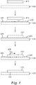
Figure 4 is a flowchart illustrating a method of making a flat multilayer optical film for use in a PBS. -
Figure 5 illustrates a method for creating a polarizing beam splitter using a multilayer optical film. - A high performance PBS is essential for creating a viable optical engine for a projector that uses Liquid Crystal on Silicon (LCOS) imagers. In addition, a PBS may be required even for nominally unpolarized imagers such as DLP imagers when such imagers are required to handle polarized light. Typically, a PBS will transmit nominally p-polarized light and reflect nominally s-polarized light. A number of different types of PBSs have been used, including MacNeille type PBSs and wire grid polarizers. However, PBSs based on multilayer optical film have proven to be one of the most effective polarizing beam splitters for issues associated with light handling in projection systems, including the ability to effectively polarize over a range of wavelengths and angles of incidence and with high efficiencies both in reflection and transmission. Such multilayer optical films are made by 3M Company, as described in
U.S. Patent No. 5,882,774 to Jonza et al. , andU.S. Patent No. 6,609,795 to Weber et al. - With the advent of a number of new imaging and projection applications, including, e.g., three-dimensional projection and imaging, new challenges have arisen. Specifically, in at least some three-dimensional imaging applications, it may be required that a PBS provide imaged light that has a high effective resolution (as defined below) not only when transmitted through a reflective polarizing film, but also when reflected by a reflective polarizing film. Unfortunately, polarizers based on multilayer optical film, despite their other major advantages, may be difficult to formulate with the requisite flatness to reflect imaged light at high resolution. Rather, where such multilayer film reflective polarizers are used to reflect imaged light, the reflected image may be distorted. However, the concerns of effectively polarizing a wide array of angles of incident light and wavelengths of incident light must still be addressed. It would therefore be highly desirable to provide a polarizing beam splitter that has the benefits of a PBS that contains multilayer optical film, while also achieving heightened effective resolution for imaged light reflected off of the PBS towards a viewer or screen. The present description provides such a solution.
-
Figure 1 provides an illustration of one polarization subsystem according to the present description. Polarization subsystem includes afirst imager 102. In a number of embodiments, such as that illustrated inFig. 1 , the imager will be an appropriate reflective imager. Often, imagers used in projection systems are typically polarization-rotating, image-forming devices, such as liquid crystal display imagers, which operate by rotating the polarization of the light to produce an image corresponding to digital video signals. Such imagers, when used in projection systems, typically rely on polarizers to separate light into a pair of orthogonal polarization states (e.g., s-polarization and p-polarization). Two common imagers that may be used in the embodiment shown inFigure 1 include a liquid crystal on silicon (LCOS) imager, or digital light processing (DLP) imager. Those skilled in the art will recognize that the DLP system will require some modification to the illumination geometry as well as an external means of rotating the polarization (such as a retarder plate) in order to make use of the PBS configuration shown inFigure 1 . The polarization subsystem also includes a polarizing beam splitter (PBS) 104.Light 112 from alight source 110 travels towardsPBS 104. WithinPBS 104 is areflective polarizer 106. The reflective polarizer may be a multilayer optical film such as those available from 3M Company (St. Paul, MN) and described in, e.g.,U.S. Patent No. 5,882,774 to Jonza et al. , andU.S. Patent No. 6,609,795 to Weber et al. , each of which is hereby incorporated by reference in its entirety. When light 112 is incident uponfilm 106, one orthogonal polarization state of the incident light, such as the p-polarized state, will be transmitted through the film and exit the PBS as light 120 that is then incident onimager 102. The orthogonal polarization state of the incident light (in this case, s-polarized light), will be reflected byreflective polarizer 106 as aseparate beam 118 in a different direction, here at right angles tobeam 120. - Unimaged light of a given
polarization state 120 is incident uponimager 102. The light is then imaged and reflected back towardsPBS 104 and incorporatedreflective polarizer 106. Where theimager 102 is an LCOS imager, and for those pixels in an "on" state, light 114 is also converted to an orthogonal polarization state. In this case, the p-polarized incident light, not yet imaged, is reflected as imaged light of s-polarization. When the s-polarized light is incident upon thepolarizing beam splitter 104, and particularly multilayer optical filmreflective polarizer 106, the light is reflected as s-polarizedbeam 116 towards a viewer orviewing screen 130. - In a number of embodiments of the prior art, the imager may be positioned, e.g., in the direction towards which
beam 118 travels. In such an embodiment imaged light would be transmitted through thepolarizing beam splitter 104 rather than reflected inpolarizing beam splitter 104. Transmitting imaged light through the polarizing beam splitter allows for less distortion of the image, and thus, higher effective resolution. However, as will be further explained, it may be desirable in a number of embodiments to include animager 102 as positioned inFigure 1 . This may, for example, allow for overlapping images of different polarizations. Despite the many benefits of multilayer optical film as a reflective polarizer, it has conventionally been difficult to achieve high effective resolution for imaged light reflected off such films. - The Effective Resolution of the image or light produced by elements is a useful quantitative measurement because it helps predict what size pixel can be reliably resolved. Most current imagers (LCOS and DLP) have a pixel size range from about 12.5 µm down to around 5 µm. So in order to be useful in a reflective imaging situation, the reflector must be able to resolve down to at least about 12.5 µm, and ideally better. Therefore the Effective Resolution of a PBS must be no more than about 12.5 µm, and preferably lower. This would be considered a high effective resolution.
- Using techniques described in the specification, one may in fact provide a multilayer optical film for use in a
PBS 104 that can reflect imaged light at very high resolution. In fact, looking toFig. 1 , imaged light 116 may be reflected from thepolarizing beam splitter 104 towards a viewer orviewing screen 130 with an effective pixel resolution of less than 12 microns. In fact, in some embodiments, the imaged light 116 may be reflected from thepolarizing beam splitter 104 towards a viewer orviewing screen 130 with an effective pixel resolution of less than 11 microns, less than 10 microns, less than 9 microns, less than 8 microns, less than 7 microns, or potentially even less than 6 microns. - As discussed, in at least some embodiments, the
polarization subsystem 100 may include asecond imager 108.Second imager 108 may generally be of the same type of imager asfirst imager 106, e.g., LCOS or DLP. Light of one polarization state, such as s-polarized light, may be reflected fromPBS 104, and specifically fromreflective polarizer 106 of the PBS towards the second imager. It may then be imaged and reflected back towardsPBS 104. Again, as with thefirst imager 104, light reflected off ofsecond imager 108 is polarization converted, such that where s-polarized unimaged light 118 is incident uponimager 108, p-polarized imaged light 122 is redirected from theimager 108 back towardsPBS 104. Whereas light 114 reflected fromimager 102 is of a first polarization state (e.g., s-pol) and therefore reflects off ofPBS 104 towards viewer orviewing screen 130, light reflected off of imager 108 (e.g. light 122) is of a second polarization (e.g., p-pol.) and therefore is transmitted throughPBS 104 towards viewer orviewing screen 130. As can be seen fromFig. 1 , the two imagers are located at different sides of thePBS 104, such that the PBS receives imaged light 114 fromfirst imager 102 at afirst face 126 and receives imaged light 122 from thesecond imager 108 at asecond face 124 different from the first face. - Once imaged
light 116 and potentially light 122 exitsPBS 104 it is directed towards a viewer orviewing screen 130. In order to best direct light to the viewer and properly scale the image, light may be passed through aprojection lens 128 or some sort of projection lens system. While only illustrated with a singleelement projection lens 128,polarization conversion system 100 may include additional imaging optics as needed. For example, theprojection lens 128 may in fact be a plurality of lenses, such as lens group 250 of commonly owned and assignedU.S. Patent No. 7,901,083 . Note that in the case thatoptional imager 108 is not used, theinput light 112 may be pre-polarized to have the same polarization state aslight beam 120. This can be accomplished for example, by the use of a polarization converting system (PCS), the addition or a reflective or absorptive linear polarizer or other such device for enhancing the polarization purity of theinput light stream 112. Such a technique may improve the overall efficiency of the system. -
PBS 104 may include other elements besidesreflective polarizer 106. For example,Figure 1 illustrates aPBS 104 that also includes afirst cover 132 and asecond cover 134.Reflective polarizer 106 is positioned betweenfirst cover 132 andsecond cover 134, such that it is both protected and properly positioned by the covers. Thefirst cover 132 andsecond cover 134 may be made of any appropriate material known in the art, such as glass, plastic or potentially other appropriate materials. It should be understood that additional materials and constructions may be applied to, e.g. the faces of the PBS or adjacent to and substantially coextensive with the reflective polarizer. Such other materials or constructions may include additional polarizers, dichroic filters/reflectors, retarder plates, anti-reflection coatings, lenses molded and/or bonded to the surface of the covers and the like. - Projection or polarization subsystems that emit light from different imagers, wherein the imaged light is of different polarizations may be especially useful as part of a three-dimensional image projector as described for example in
US Pat. No. 7,690,796 (Bin et al. ). The distinct advantage of using a PBS based two imager system is that no time sequencing or polarization sequencing is required. This means that both imagers are operating at all times, effectively doubling the light output of the projector. As discussed, it is highly important that thereflective polarizer 106 be flat, such that the imaged light 116 reflected off of the polarizer is not distorted and has high effective resolution. Flatness can be quantified by the standard roughness parameters Ra (the average of the absolute value of the vertical deviation of the surface from the mean), Rq (the root mean squared average of the vertical deviation of the surface from the mean), and Rz (the average distance between the highest peak and lowest valley in each sampling length). Specifically, the reflective polarizer preferably has a surface roughness Ra of less than 45 nm or a surface roughness Rq of less than 80 nm, and more preferably has a surface roughness Ra of less than 40 nm or a surface roughness Rq of less than 70 nm, and even more preferably has a surface roughness Ra of less than 35 nm or a surface roughness Rq of less than 55 nm. One exemplary method of measuring the surface roughness or flatness of the film is provided in the Examples section below. - In another aspect, the present description relates to a polarizing beam splitter. One such polarizing beam splitter 200 is illustrated in
Fig. 2 . Polarizing beam splitter 200 includes areflective polarizer 206 that is positioned between afirst cover 232 and asecond cover 234. As withreflective polarizer 106 ofFig. 1 , thereflective polarizer 206 ofFig. 2 is a multilayer optical film such as those described above. The polarizing beam splitter 200 is capable of reflecting imaged light 216 towards a viewer orsurface 230. The effective pixel resolution of the imaged light 216 that is directed towards the viewer or surface is less than 12 microns, and possibly less than 11 microns, less than 10 microns, less than 9 microns, less than 8 microns, less than 7 microns, or potentially even less than 6 microns. - As with the covers of
Figure 1 ,first cover 232 andsecond cover 234 of PBS 200 may be made of any number of appropriate materials used in the field, such as glass or optical plastics, among others. In addition, thefirst cover 232, andsecond cover 234 may each be attached toreflective polarizer 206 by a number of different means. For instance, in one embodiment, thefirst cover 232 may be attached to thereflective polarizer 206 using a pressure sensitiveadhesive layer 240. A suitable pressure sensitive adhesive is 3M™ Optically Clear Adhesive 8141 (available from 3M Company, St. Paul, MN). Similarly, thesecond cover 234 may be attached to the reflective polarizer using a pressure sensitiveadhesive layer 242. In other embodiments, the first and second cover may be attached toreflective polarizer 206 using different adhesive types forlayer U.S. Patent Publication No. 2006/0221447 (to DiZio et al. ) and commonly owned and assignedU.S. Patent Publication No. 2008/0079903 (to DiZio et al. ), each of which is hereby incorporated by reference. UV curable adhesives may also be used. It should be understood that additional materials and constructions may be applied to, e.g. the faces of the PBS or adjacent to and substantially coextensive with the reflective polarizer. Such other materials or constructions may include additional polarizers, dichroic filters/reflectors, retarder plates, anti-reflection coatings, and the like. As with the PBS described inFig. 1 , thereflective polarizer 206 ofFig. 2 must be very flat to most effectively reflect imaged light 216 without distorting it. The reflective polarizer may have a surface roughness Ra of less than 45 nm or a surface roughness Rq of less than 80 nm.. With typical application procedures of pressure sensitive adhesives such as described inUS 7,234,816 B2 (Bruzzone et al. ) the required surface flatness of the reflective polarizer is not achieved. It has been discovered that certain types of postprocessing, allow the required surface flatness to be achieved. - In yet another aspect, the present description relates to a projection subsystem. One such projection subsystem is illustrated in
Figure 3 .Projection subsystem 300 includes alight source 310.Light source 310 may be any number of appropriate light sources commonly used in projection systems. For example, thelight source 310 may be a solid-state emitter such as a laser or light emitting diode (LED) emitting light of a specific color such as red, green, or blue light. Thelight source 310 may also include a phosphor or other light converting material that absorbs light from the emissive source and re-emits light at other (generally longer) wavelengths. Suitable phosphors include well known inorganic phosphors such as Ce-doped YAG, strontium thiogallate, and doped silicate and SiAlON-type materials. Other light converting materials include III-V and II-VI semiconductors, quantum dots, and organic fluorescent dyes. Alternatively, the light source may be made up of a plurality of light sources, such as a red, a green and a blue LED, where such LEDs may be activated together or sequentially.Light source 310 may also be a laser light source, or potentially a traditional UHP lamp. It is to be understood that ancillary components such as color wheels, dichroic filters or reflectors and the like may additionally compriselight source 310. - The
projection subsystem 300 further includes apolarizing beam splitter 304.Polarizing beam splitter 304 is positioned such that it receives light 312 from the light source. This incident light 312 may generally be made up in part of two orthogonal polarization states, e.g., part s-polarized light, and part p-polarized light. Within the polarizing beam splitter is a reflective polarizer 306, again in this case a multilayer optical film such as those described with respect toreflective polarizer 106.Light 312 is incident upon reflective polarizer 306 and light of one first polarization, e.g., p-polarized light is transmitted through as light 320 while light of a second orthogonal polarization, e.g. s-polarized light, is reflected as light 318. - Light of the
first polarization 320 that is transmitted through the reflective polarizer 306 travels towards afirst imager 302 that is positioned adjacent to thePBS 304. Light is imaged and reflected at thefirst imager 302 back towardsPBS 304 with the polarization of the light converted. The converted imaged light 314 is then reflected at thePBS 304 as light 316 towards animage plane 350. The light 316 is reflected off of the reflective polarizer 306 of the PBS and reachesimage plane 350 with an effective resolution of less than 12 microns, and possibly less than 11 microns, less than 10 microns, less than 9 microns, less than 8 microns, less than 7 microns, or potentially even less than 6 microns. The reflective polarizer 306 typically has a surface roughness Ra of less than 45 nm or a surface roughness Rq of less than 80 nm. - Light of the second polarization (e.g. s-polarized) light that is reflected initially by the reflective polarizer of
PBS 304 travels as light 318 towards asecond imager 308.Second imager 308 is also positioned adjacent thePBS 304, as withfirst imager 302, but second imager is positioned on a different side of the PBS. The incident light 318 is imaged and reflected back towardsPBS 304. Upon reflection from the imager, the polarization of this light is rotated as well by 90 degrees (e.g. from s-polarized light to p-polarized light). The imagedlight 322 is transmitted through thePBS 304 to theimage plane 350. Thefirst imager 302 andsecond imager 308 may be any appropriate type of reflective imager, such as those described above with respect toelements Fig. 1 . - As discussed, in order to achieve high effective resolution for imaged light reflected off of the PBS herein, the reflective polarizer of the PBS must be exceptionally optically flat. The present description now provides methods of producing an optically flat reflective polarizer that is a multilayer optical film and/or methods of producing an optically flat polarizing beam splitter.
- One such method is illustrated in the flowchart of
Figure 4 . The method begins with providing a multilayeroptical film 410, and providing aflat substrate 420. The multilayeroptical film 410 may be similar to the multilayer optical films described with respect to the articles above. The flat substrate may be any number of appropriate materials, such as acrylic, glass or other appropriate plastics. Most importantly, thesubstrate 420 must possess at least the same degree of optical flatness as is required in the polarizing beam splitter and must allow a wetting solution to spread over its surface. Therefore, other plastics, inorganic glasses, ceramics, semiconductors, metals or polymers may be appropriate materials. Additionally it is useful for the substrate to be slightly flexible. - In the next step, the
surface 425 of the flat substrate is releasably attached to a first surface of the multilayer optical film. In at least one embodiment, in order to create a releasable attachment, either thesurface 425 of the flat substrate, or a first surface of the multilayer optical film, or both is wetted with a wetting agent, resulting in a thin layer ofsolution 430. A suitable wetting agent should have a surface energy that is sufficiently low that it will wet out the substrate or the film and a vapor pressure that is sufficiently high that it can evaporate at room temperature. In some embodiments, isopropyl alcohol is used as the wetting agent. In at least some embodiments the wetting agent will be an aqueous solution that contains at least a small amount of surfactant (e.g. less than 1% by volume). The surfactant may be common commercially available industrial wetting agents, or even household materials such as dishwashing detergent. Other embodiments may be aqueous mixtures of compounds that leave no residue upon evaporation such as ammonia, vinegar, or alcohol. The wetting agent may be applied by a number of appropriate methods including spraying, e.g., from a spray bottle. In the next step, the multilayer optical film is applied to the surface of thesubstrate 425 such that thesolution 430 is sandwiched between the film and substrate. Typically the wetting agent is applied to the contacting surface of the multilayer optical film also. Apressure applying instrument 435, such as a squeegee is then drawn across the top of multilayeroptical film 410 closely flatteningoptical film 410 to thesurface 425 ofsubstrate 420, and leaving only a thin, fairly uniform layer ofsolution 430 separating the two. In at least some embodiments, a protective layer may first be applied to the multilayer optical film on the side opposite thesurface 440 that is applied to thesubstrate 420. At this point, the construction is left to allow thesolution 430 to evaporate. The squeegeeing process pushes residual water past the edges of the multilayer optical film such that only a small amount remains. Next, the multilayer optical film, flat substrate, and wetting agent are allowed to dry. With time, all of the volatile components of the wetting solution evaporate either throughlayers layers layer 410 where evaporation can occur. As this process occurs, the multilayeroptical film 410 is drawn closer and closer tosubstrate 420 untillayer 410 closely conforms to thesurface 425. The result is shown in the next step ofFigure 4 , as the drying closely draws thefilm 410 tosubstrate 420 and effectively flattens thebottom surface 440 of the multilayer optical film. Once this flatness has been achieved, the multilayeroptical film 410 remains stably flat but releasably attached to the substrate. At this point a permanent substrate may be adhered to the exposed surface of thefilm 410. -
Figure 5 illustrates further steps that may be taken in providing a final construction of a polarizing beam splitter. For example, an adhesive 550 may be applied on the flattened surface 450 offilm 410. The adhesive may be any appropriate adhesive that does not adversely affect the optical or mechanical performance of the PBS. In some embodiments, the adhesive may be a curable optical adhesive, such as NOA73, NOA75, NOA76 or NOA78 from Norland Products Inc. (Cranbury, NJ). In other embodiments, optical epoxies may be used. In some embodiments, the adhesive may be a pressure sensitive adhesive. Next, one may provide a permanent second substrate. In one embodiment, the permanent second substrate may be a prism. As shown inFigure 5 ,Prism 560 is applied against the adhesive 550 and the construction is cured if appropriate. Thefilm 410 may now be removed from thesubstrate 420. In at least one embodiment, thefilm 410 is peeled away fromsubstrate 420, typically by flexingsubstrate 420 slightly to allow thefilm 410 to release fromsubstrate 420. For cured adhesives such as UV adhesives or epoxies the newly exposed bottom surface of thefilm 440 retains the flatness of thesubstrate 420. For pressure sensitive adhesives, the bottom surface of thefilm 440 may retain the flatness of thesubstrate 420 or may require additional processing to maintain the flatness. Once theflat film surface 440 has been achieved a second layer of adhesive 570 may be applied to the bottom surface of thefilm 440 and a second prism or otherpermanent substrate 580 may be applied to the adhesive. Again the construction may be cured as needed, resulting in a complete polarizing beam splitter. - Another method of making an optically flat polarizing beam splitter includes the use, specifically, of pressure sensitive adhesives. With appropriate techniques, the multilayer optical film may be made to conform closely to the flat surface of the prism. The following steps may be included. First, a multilayer optical film is provided. The multilayer optical film will act as a reflective polarizer. This may be similar to reflective polarizer
optical film 410 ofFig. 5 with the exception that thesurface 440 may not be substantially flattened already through the steps shown inFig. 4 . A layer of pressure sensitive adhesive (here corresponding to adhesive layer 550) may be applied to thefirst surface 440 of the multilayer optical film. Next aprism 560 may be applied against the pressure sensitive adhesive layer adhesive layer on the side opposite the multilayeroptical film 410. The method may also include applying a second layer of adhesive (e.g. layer 570) on asecond surface 575 of the film oppositefirst surface 440. Asecond prism 580 may then be applied to the opposite side oflayer 570 fromfilm 410. The present method provides an improvement over this method that further enhances the flatness of the reflective polarizer/prism interface, such that imaged reflection off of the PBS has enhanced resolution. After pressuresensitive adhesive 550 is applied between theprism 560 and multilayeroptical film 410, the construction is subjected to vacuum. This may occur, for example, by placing the construction in a vacuum chamber equipped with a conventional vacuum pump. The vacuum chamber may be lowered to a given pressure, and the sample may be held at that pressure for a given amount of time, e.g., 5 -20 minutes. When air is re-introduced to the vacuum chamber, the air pressure pushes theprism 560 and multilayeroptical film 410 together. Where a second adhesive layer and second prism are also applied, the subjection to vacuum in the chamber may optionally be repeated for the second interface (e.g. at layer 570). Applying vacuum to a prism/MOF assembly results in a PBS that provides heightened effective resolution when imaged light is reflected off of the PBS. In place of or in conjunction with the vacuum treatment, a thermal/pressure treatment may also be used. It may be advantageous to conduct the processing more than one time. - The following list of materials and their source is referred to throughout the Examples. If not otherwise specified, materials are available from Aldrich Chemical (Milwaukee, WI). Multilayer Optical Films (MOFs) were generally prepared according to methods described in, for example,
U.S. 6,179,948 (Merrill et al );6,827,886 (Neavin et al );2006/0084780 (Hebrink et al );2006/0226561 (Merrill et al. ); and2007/0047080 (Stover et al. ). - Prisms were placed on modeling clay and leveled using a plunger leveler. Topographic maps were measured with a Wyko® 9800 optical interferometer (available from Veeco Metrology, Inc., Tucson, AZ), with a 10x objective and 0.5x field lens and with the following settings: VSI detection; 4 mm x 4 mm scan area stitched using 6 rows and 5 columns of individual maps, 2196x2196 pixels with a sampling of 1.82 µm; tilt and sphere correction used; 30-60 microns back scan length with 60-100 forward scan length; with the modulation detection threshold 2% . Autoscan detection was enabled at 95% with 10 µm post scan length (this short post scan length avoided subsurface reflections in the data collection).
- A 4 mm x4 mm area in the central region of the hypotenuse-face of each prism was measured. Specifically, the topography of each region was measured, plotted, and the roughness parameters Ra, Rq and Rz were calculated. One measurement area was obtained per prism. Three prism samples were measured in each case and the mean and standard deviation of the roughness parameters were determined.
- A reflective polarizing multilayer optical film (MOF) was releasably disposed onto an optically flat substrate in the following manner. First a wetting solution comprising approximately 0.5% mild dishwashing detergent in water was placed into a spray bottle. A sheet of approximately 6 mm high-gloss acrylic was obtained and the protective layer removed from one side in a clean hood. The exposed acrylic surface was sprayed with the wetting solution so that the entire surface was wet. Separately a piece of MOF was obtained and one of its skin layers was removed in a clean hood. The exposed surface of the MOF was sprayed with the wetting solution, and the wet surface of the MOF was contacted with the wet surface of the acrylic sheet. A heavy release liner was applied to the surface of the MOF to prevent damage to the MOF, and a 3M™ PA-1 applicator (available from 3M Company, St. Paul, MN) was used to squeegee the MOF down to the surface of the acrylic. This resulted in most of the wetting solution being expelled from between the two wetted surfaces. After this was done the second skin layer from the MOF was removed. Inspection of the applied MOF showed that the MOF surface was much more irregular than the surface of the acrylic. Upon inspection again after 24 hours, the MOF surface was observed to be comparable in flatness to the acrylic sheet. This observed flattening over time is consistent with residual wetting solution evaporating from between the two surfaces allowing the MOF to conform closely to the surface of the acrylic. Even though the MOF conformed closely and stably to the surface of the acrylic, it could be easily removed by peeling the MOF from the surface of the acrylic.
- An imaging PBS was prepared by placing a small amount of Norland Optical Adhesive 73 (available from Norland Products, Cranbury, NJ) onto the surface of the MOF. The hypotenuse of a 10 mm 45° BK7 polished glass prism was slowly placed into contact with the adhesive so that no bubbles were entrained in the adhesive. The amount of adhesive was chosen so that when the prism was placed on to the adhesive, there was sufficient adhesive to flow out to the edges of the prism, but not so much adhesive to cause substantial overflow of the adhesive beyond the perimeter of the prism. The result was that the prism was substantially parallel to the surface of the MOF and separated by a layer of adhesive of approximately uniform thickness.
- A UV curing lamp was used to cure the adhesive layer through the prism. After curing, a section of the MOF that was larger than the prism and that contained the prism was peeled away from the acrylic substrate. Removal was facilitated by bending the acrylic plate, thereby allowing the rigid prism and MOF composite to separate more easily from the acrylic plate. Inspection of the prism/MOF composite showed that the MOF retained its flatness despite being removed from the acrylic plate.
- The roughness parameters of the MOF were then measured as described under "Roughness Measurement Method" and are reported in the following table.
average stdev Ra (nm) 34 12 Rq (nm) 51 30 Rz (µm) 6.7 8.5 - A small amount of the Norland optical adhesive was applied to the MOF surface on the prism/MOF composite. A second 10 mm 45° prism was procured and its hypotenuse placed in contact with the adhesive. The second prism was aligned such that its principal and secondary axes were substantially parallel to those of the first prism, and the two hypotenuse surfaces were substantially coextensive. A UV curing lamp was used to cure the adhesive layer so that the second 45° prism was bonded to the prism/MOF composite. The resulting configuration was a polarizing beam splitter.
- An adhesive construction was formed by taking a sample of 3M™ Optically Clear Adhesive 8141 (available from 3M Company, St. Paul, MN) and laminating it to a reflective polarizing MOF using a roll lamination process. A piece of this adhesive construction was adhered to the hypotenuse of a glass prism similar to that used in Example 1. The resulting MOF/prism composite was placed into an autoclave oven and processed at 60° C and 550 kPa (80 psi) for two hours. The sample was removed and a small quantity of thermally curable optical epoxy was applied to the MOF surface of the MOF/prism composite. The prisms were aligned as in Example 1. The sample was then returned to the oven and again processed at 60° C and 550 kPa (80 psi), this time for 24 hours. The resulting configuration was a polarizing beam splitter.
- The roughness of MOF produced using the method of Example 2 was determined as follows. A piece of MOF measuring 17 mm x 17 mm was laminated using a hand roller to a glass cube having a width of 17 mm. The glass cube had a flatness of about 0.25 lambda, where lambda equaled 632.80 nm (a reference wavelength of light). The roll-laminated MOF was annealed in an autoclave oven at 60 °C and 550 kPa (80 psi) for two hours. A Zygo Interferometer (available from Zygo Corporation, Middlefield CT) was used to measure the flatness of the roll-laminated MOF using light having a wavelength of lambda = 632.80 nm. The Zygo Interferometer reported a peak to valley roughness, where a tilt correction was used and no sphere correction was applied. The peak to valley roughness measured over the 17 mm x 17 mm area was determined to be 1.475 lambda or about 933 nm.
- A piece of the adhesive construction of Example 2 was adhered to a glass prism in a manner similar to that in Example 2. The resulting prism/MOF composite was placed into a vacuum chamber equipped with a conventional vacuum pump. The chamber was evacuated to around 71 cm (28 inches) of Hg, and of the sample held under vacuum for about 15 minutes.
- The sample was removed from the vacuum chamber and the roughness parameters of the MOF were measured as described under "Roughness Measurement Method." and the measured values are reported in the following table.
average stdev Ra (nm) 32 3 Rq (nm) 40 5 Rz (µm) 1.2 0.7 - A second prism was attached to the prism/MOF composite using the technique and the UV optical adhesive of Example 1. The resulting configuration was a polarizing beam splitter.
- A polarizing beam splitter configuration was created according to
U.S. 7, 234,816 (Bruzzone et al. ). A piece of the adhesive construction of Example 2 was adhered to a glass prism using a hand roller thereby forming an MOF/prism composite. - The roughness parameters of the MOF were then measured as described under "Roughness Measurement Method" and are reported in the following table.
average stdev Ra (nm) 65 20 Rq (nm) 100 18 Rz (µm) 8.6 5.1 - A second prism was attached to the prism/MOF composite using the technique and the UV optical adhesive of Example 1. The resulting configuration was a polarizing beam splitter.
- The polarizing beam splitters of Example 1, 2, 3 and Comparative Example C-1 were assessed for their ability to reflect an image using a resolution test projector. A reference reflector consisting of one of the 45° prisms used in the other examples and operating as a total internal reflection (TIR) reflector was used to establish the best possible performance for the test projector.
- A test target with 24X reduction was back illuminated with an arc lamp light source. Attached to the front surface of the test target was a 45° prism, identical to those used in earlier examples (and herein called the illumination prism). Light from the test target, traveling horizontally from the source through the test target, entered one face of the illumination prism, reflected off of the hypotenuse (via TIR) and exited the second face of the prism. The second face of the prism was oriented such that the exiting light was directed vertically. The various PBSs from the examples, as well as the reference prism were placed on top of the second face of the illumination prism. The reflecting surface (MOF) in the PBSs as well as the hypotenuse from the reference prism were oriented such that the light reflecting from the MOF or the hypotenuse of the reference prism were directed forward and horizontal. An F/2 .4 projection lens obtained from a 3M™ SCP 712 digital projector (available from 3M Company, St. Paul, MN) was placed at the exit surface of the PBS or the reference prism and focused back onto the test target, forming a kind of "periscope" layout.
- This optical system was then used to assess the ability of each different PBS to resolve a test target while operating in a reflection mode. In the system, an approximately 5 mm x 5 mm portion of the test target was projected to about 150 cm (60 inches) diagonal. Within this area of the test target were multiple repeats of the resolution images. Five different identical repeats of the test target were assessed in different locations of the projected image: Top Left, Bottom Left, Center, Top Right and Bottom Right. Each test target was assessed to determine the highest resolution that was clearly resolved. According to the protocol, the maximum resolution was required to be resolved as well as all resolutions below that level. There were instances where localized distortions caused lower resolutions to not be resolved even though higher resolutions (in a slightly different location) were resolved. The reason for this choice is that the full field and not just small areas must be resolved in order for the PBS to function effectively in a reflective mode.
- Multiple samples of each Example were tested. Once the maximum resolutions were established for each location on each PBS, an average and a standard deviation were computed for each type of prism (that is, for Examples 1 - 3, Comparative Example C-1 and the Reference prism.) An "Effective Resolution" was defined as the average minus two standard deviations. This metric was determined from the data in "line pairs/mm" (lp/mm) and then expressed in terms of the size of the smallest resolvable pixel which was determined as ½ of the inverse of the Effective Resolution expressed in lp/mm. This definition accounts for the fact that the resolution is only as good as the minimum resolution across the field. The Effective Resolution represents the maximum resolution that the particular PBS set can be expected to reliably (across 95% of the image) resolve.
- Table 1 shows the results of the measurements of the different Examples within this disclosure and Table 2 shows the resulting Effective Resolution. As can be seen, the reference sample can resolve a 5 µm pixel. The PBS from Example 1 can also resolve a very nearly 5 µm pixel. Example 2 is able to resolve down to at least 12 µm and the PBS from Example 3 can resolve down to 7 µm. All of these constructions should be adequate for at least some reflective imaging applications. On the other hand, the PBS from Comparative Example C-1 is limited to resolving around 18 micron pixels, and would likely not be a robust choice for a reflective imaging construction.
Table 1: Line Pairs/mm at Five Locations for Samples Example Sample Top Right (lp/mm) Bottom Right (lp/mm) Center (lp/mm) Bottom Left (lp/mm) Top Left (lp/mm) Reference A 170.4 170.4 108.0 192.0 170.4 1 B 151.2 170.4 120.0 151.2 120.0 1 C 151.2 151.2 108.0 120.0 151.2 1 D 151.2 151.2 108.0 134.4 120.0 2 E 151.2 134.4 60.0 108.0 86.4 2 F 134.4 134.4 67.2 96.0 96.0 2 G 134.4 134.4 96.0 60.0 76.8 3 H 134.4 134.4 96.0 86.4 120.0 3 I 134.4 151.2 108.0 96.0 96.0 C-1 J 151.2 134.4 48.0 60.0 76.8 C-1 K 120.0 134.4 60.0 96.0 60.0 C-1 L 120.0 120.0 60.0 86.4 86.4 C-1 M 134.4 120.0 60.0 60.0 86.4 Table 2: Effective Resolution of Exemplary Film Example Average (lp/mm) Std. Dev. (lp/mm) Effective Resolution (lp/mm) Effective Resolution (µm) Reference 162.2 31.7 98.8 5.06 1 137.3 19.6 98.1 5.10 2 104.6 30.9 42.9 11.65 3 115.7 22.1 71.4 7.00 C-1 93.7 32.8 28.2 17.74 - The present invention should not be considered limited to the particular examples and embodiments described above, as such embodiments are described in detail to facilitate explanation of various aspects of the invention. Rather the present invention should be understood to cover all aspects of the invention, including various modifications, equivalent processes, and alternative devices falling within the spirit and scope of the invention as defined by the appended claims.
Claims (4)
- A polarization subsystem comprising:a first imager; anda polarizing beam splitter receiving imaged light from the imager, the polarizing beam splitter comprising a reflective polarizer;wherein the reflective polarizer comprises a multilayer optical film, and whereinthe polarizing beam splitter reflects imaged light towards a viewer or screen, and whereinthe reflective polarizer has a surface roughness Ra of less than 45 nm or a surface roughness Rq of less than 80 nm.
- The projection subsystem of claim 1, wherein the reflective polarizer has a surface roughness Ra of less than 40 nm or a surface roughness Rq of less than 70 nm.
- The projection subsystem of claim 1, wherein the reflective polarizer has a surface roughness Ra of less than 35 nm or a surface roughness Rq of less than 55 nm.
- A three-dimensional image projector comprising the polarization subsystem of claim 1.
Applications Claiming Priority (2)
| Application Number | Priority Date | Filing Date | Title |
|---|---|---|---|
| US201161564161P | 2011-11-28 | 2011-11-28 | |
| EP12798948.1A EP2786197A1 (en) | 2011-11-28 | 2012-11-14 | Polarizing beam splitters providing high resolution images and systems utilizing such beam splitters |
Related Parent Applications (1)
| Application Number | Title | Priority Date | Filing Date |
|---|---|---|---|
| EP12798948.1A Division EP2786197A1 (en) | 2011-11-28 | 2012-11-14 | Polarizing beam splitters providing high resolution images and systems utilizing such beam splitters |
Publications (1)
| Publication Number | Publication Date |
|---|---|
| EP3203307A1 true EP3203307A1 (en) | 2017-08-09 |
Family
ID=47326345
Family Applications (2)
| Application Number | Title | Priority Date | Filing Date |
|---|---|---|---|
| EP17162174.1A Withdrawn EP3203307A1 (en) | 2011-11-28 | 2012-11-14 | Polarizing beam splitters providing high resolution images and systems utilizing such beam splitters |
| EP12798948.1A Withdrawn EP2786197A1 (en) | 2011-11-28 | 2012-11-14 | Polarizing beam splitters providing high resolution images and systems utilizing such beam splitters |
Family Applications After (1)
| Application Number | Title | Priority Date | Filing Date |
|---|---|---|---|
| EP12798948.1A Withdrawn EP2786197A1 (en) | 2011-11-28 | 2012-11-14 | Polarizing beam splitters providing high resolution images and systems utilizing such beam splitters |
Country Status (7)
| Country | Link |
|---|---|
| US (4) | US9535256B2 (en) |
| EP (2) | EP3203307A1 (en) |
| JP (1) | JP6161622B2 (en) |
| KR (1) | KR20140098203A (en) |
| CN (2) | CN104185809A (en) |
| TW (1) | TWI588542B (en) |
| WO (1) | WO2013081822A1 (en) |
Families Citing this family (21)
| Publication number | Priority date | Publication date | Assignee | Title |
|---|---|---|---|---|
| EP3203307A1 (en) * | 2011-11-28 | 2017-08-09 | 3M Innovative Properties Company | Polarizing beam splitters providing high resolution images and systems utilizing such beam splitters |
| US10477194B2 (en) | 2012-04-25 | 2019-11-12 | 3M Innovative Properties Company | Two imager projection device |
| US9851576B2 (en) | 2012-08-15 | 2017-12-26 | 3M Innovative Properties Company | Polarizing beam splitter plates providing high resolution images and systems utilizing such polarizing beam splitter plates |
| CN104781723B (en) | 2012-08-21 | 2017-09-15 | 3M创新有限公司 | Viewing apparatus |
| JP6453217B2 (en) | 2012-08-22 | 2019-01-16 | スリーエム イノベイティブ プロパティズ カンパニー | Polarizing beam splitter and manufacturing method thereof |
| US9958699B2 (en) | 2012-12-21 | 2018-05-01 | 3M Innovative Properties Company | Hybrid polarizing beam splitter |
| CA2955942A1 (en) * | 2014-07-22 | 2016-01-28 | Barco, Inc. | Display systems and methods employing polarizing reflective screens |
| US9726891B2 (en) * | 2015-09-03 | 2017-08-08 | Microsoft Technology Licensing, Llc | Left and right eye optical paths with shared optical element for head-mounted display device |
| CN114137729A (en) * | 2016-02-24 | 2022-03-04 | 奇跃公司 | Polarizing beam splitter with low light leakage |
| US10185153B2 (en) | 2016-08-12 | 2019-01-22 | Avegant Corp. | Orthogonal optical path length extender |
| US10809546B2 (en) | 2016-08-12 | 2020-10-20 | Avegant Corp. | Digital light path length modulation |
| US10057488B2 (en) | 2016-08-12 | 2018-08-21 | Avegant Corp. | Image capture with digital light path length modulation |
| US10401639B2 (en) | 2016-08-12 | 2019-09-03 | Avegant Corp. | Method and apparatus for an optical path length extender |
| US10516879B2 (en) | 2016-08-12 | 2019-12-24 | Avegant Corp. | Binocular display with digital light path length modulation |
| US10187634B2 (en) | 2016-08-12 | 2019-01-22 | Avegant Corp. | Near-eye display system including a modulation stack |
| US10379388B2 (en) | 2016-08-12 | 2019-08-13 | Avegant Corp. | Digital light path length modulation systems |
| CN107505806B (en) * | 2017-09-08 | 2020-06-30 | 海信视像科技股份有限公司 | DMD modulation imaging system and laser projection equipment |
| CN107422484B (en) | 2017-09-19 | 2023-07-28 | 歌尔光学科技有限公司 | Prismatic AR display device |
| US11726246B2 (en) | 2017-10-20 | 2023-08-15 | 3M Innovative Properties Company | Optical film and polarizing beam splitter |
| JP7326287B2 (en) | 2017-12-20 | 2023-08-15 | スリーエム イノベイティブ プロパティズ カンパニー | Optical Stacks and Polarizing Beamsplitters |
| US20220004015A1 (en) | 2018-12-07 | 2022-01-06 | 3M Innovative Properties Company | Optical film and polarizing beam splitter |
Citations (17)
| Publication number | Priority date | Publication date | Assignee | Title |
|---|---|---|---|---|
| US5882774A (en) | 1993-12-21 | 1999-03-16 | Minnesota Mining And Manufacturing Company | Optical film |
| US6179948B1 (en) | 1998-01-13 | 2001-01-30 | 3M Innovative Properties Company | Optical film and process for manufacture thereof |
| US6328447B1 (en) * | 1997-12-03 | 2001-12-11 | Seiko Epson Corporation | Projection device |
| WO2002095487A1 (en) * | 2001-05-18 | 2002-11-28 | 3M Innovative Properties Company | Polarization arrangement |
| US20030071938A1 (en) * | 2001-10-16 | 2003-04-17 | Eiji Hamamoto | Method of producing polarizing plate, and liquid crystal display comprising the polarizing plate |
| US6609795B2 (en) | 2001-06-11 | 2003-08-26 | 3M Innovative Properties Company | Polarizing beam splitter |
| US6827886B2 (en) | 1998-01-13 | 2004-12-07 | 3M Innovative Properties Company | Method for making multilayer optical films |
| US20050185139A1 (en) * | 2004-02-25 | 2005-08-25 | Olympus Corporation | Light modulating unit and image projection apparatus |
| US20060084780A1 (en) | 2004-10-18 | 2006-04-20 | Hebrink Timothy J | Modified copolyesters and optical films including modified copolyesters |
| US20060221447A1 (en) | 2005-03-31 | 2006-10-05 | 3M Innovative Properties Company | Stabilized polarizing beam splitter assembly |
| US20060226561A1 (en) | 2005-04-08 | 2006-10-12 | 3M Innovative Properties Company | Heat setting optical films |
| US20070047080A1 (en) | 2005-08-31 | 2007-03-01 | 3M Innovative Properties Company | Methods of producing multilayer reflective polarizer |
| US7234816B2 (en) | 2004-02-03 | 2007-06-26 | 3M Innovative Properties Company | Polarizing beam splitter assembly adhesive |
| US20080079903A1 (en) | 2006-09-29 | 2008-04-03 | 3M Innovative Properties Company | Adhesives inhibiting formation of artifacts in polymer based optical elements |
| US20090046253A1 (en) * | 2007-08-17 | 2009-02-19 | Toshihiro Sunaga | Polarizing beam splitter, projection optical sysem, projection display |
| US7690796B2 (en) | 2003-07-18 | 2010-04-06 | Kinoptics Technologies Inc. | Color projection display system |
| US7901083B2 (en) | 2006-07-31 | 2011-03-08 | 3M Innovative Properties Company | Optical projection subsystem |
Family Cites Families (39)
| Publication number | Priority date | Publication date | Assignee | Title |
|---|---|---|---|---|
| US5725626A (en) * | 1986-06-18 | 1998-03-10 | Canon Kabushiki Kaisha | Method for manufacturing an optical element by bonding a plurality of elements |
| JPH05168046A (en) | 1991-12-13 | 1993-07-02 | Sony Corp | Stereoscopic video display device |
| JP2725606B2 (en) | 1994-08-25 | 1998-03-11 | 日本電気株式会社 | LCD projector device |
| US6486997B1 (en) | 1997-10-28 | 2002-11-26 | 3M Innovative Properties Company | Reflective LCD projection system using wide-angle Cartesian polarizing beam splitter |
| US6636276B1 (en) | 1999-09-09 | 2003-10-21 | International Business Machines Corporation | Projection display system with at least two reflective light valves |
| JP2001272513A (en) | 2000-03-24 | 2001-10-05 | Seiko Epson Corp | Optical parts and projector using the same |
| US6563551B1 (en) * | 2000-06-28 | 2003-05-13 | Koninklijke Philips Electronics N.V. | High contrast polarizing optics for a color electro-optic display device |
| AU2002234137A1 (en) | 2000-11-02 | 2002-05-15 | Corning Precision Lens Incorporated | Optical systems for reflective lcds |
| US6698896B2 (en) | 2001-01-19 | 2004-03-02 | Victor Company Of Japan, Ltd. | Color-separating and -recombining optical system and projection display using the same |
| CN1302298C (en) * | 2001-10-16 | 2007-02-28 | 日东电工株式会社 | Method for mfg. polaroid and liquid crystal display device |
| US7002752B2 (en) | 2001-11-30 | 2006-02-21 | Colorlink, Inc. | Three-panel color management systems and methods |
| BR0316832A (en) | 2002-12-04 | 2005-10-18 | Thomson Licensing Sa | High contrast stereoscopic projection system |
| US7237899B2 (en) | 2003-05-16 | 2007-07-03 | 3M Innovative Properties Company | Highly efficient single panel and two panel projection engines |
| JP4337691B2 (en) | 2003-10-31 | 2009-09-30 | 日本ビクター株式会社 | Image display device |
| JP4033137B2 (en) * | 2004-01-30 | 2008-01-16 | ソニー株式会社 | Projection-type image display device and optical system |
| US7360900B2 (en) | 2004-03-10 | 2008-04-22 | Seiko Epson Corporation | Illuminating apparatus, image display apparatus, and projector |
| KR20050109217A (en) | 2004-05-14 | 2005-11-17 | 삼성전자주식회사 | Two panel type projection system and projection method thereof |
| EP1610565A1 (en) | 2004-06-25 | 2005-12-28 | Sony Deutschland GmbH | Projector arrangement |
| US8545030B2 (en) * | 2004-07-12 | 2013-10-01 | Gentex Corporation | Rearview mirror assemblies with anisotropic polymer laminates |
| JP4913996B2 (en) | 2004-09-16 | 2012-04-11 | キヤノン株式会社 | Projection type image display device |
| WO2006060236A2 (en) | 2004-11-23 | 2006-06-08 | Fergason Patent Properties, Llc | Monitor for showing high-resolution and three-dimensional images |
| US7429111B2 (en) | 2004-12-06 | 2008-09-30 | Jds Uniphase Corporation | Two-panel color management system |
| US7357511B2 (en) * | 2005-03-23 | 2008-04-15 | 3M Innovative Properties Company | Stress birefringence compensation in polarizing beamsplitters and systems using same |
| EP2046066A1 (en) | 2005-03-31 | 2009-04-08 | Sony Deutschland Gmbh | Image generation unit with four primary colors |
| DE102005020539A1 (en) | 2005-05-03 | 2006-11-09 | Carl Zeiss Jena Gmbh | Arrangement for producing a multicolored image on a projection surface |
| US7529029B2 (en) | 2005-07-29 | 2009-05-05 | 3M Innovative Properties Company | Polarizing beam splitter |
| US7445341B2 (en) | 2005-09-21 | 2008-11-04 | 3M Innovative Properties Company | Four panel liquid crystal display system |
| US20070297052A1 (en) | 2006-06-26 | 2007-12-27 | Bin Wang | Cube wire-grid polarizing beam splitter |
| WO2008002541A2 (en) | 2006-06-26 | 2008-01-03 | Moxtek, Inc. | Cube wire-grid polarizing beam splitter and projection display with same |
| US7690794B2 (en) | 2006-07-02 | 2010-04-06 | Simon Andrew Boothroyd | Image-combining device and projection display apparatus having image-combining devices incorporated therein |
| TW200819899A (en) | 2006-07-31 | 2008-05-01 | 3M Innovative Properties Co | Combination camera/projector system |
| US8388138B1 (en) * | 2007-03-11 | 2013-03-05 | Simon Boothroyd | Projection display systems |
| US9254789B2 (en) * | 2008-07-10 | 2016-02-09 | Gentex Corporation | Rearview mirror assemblies with anisotropic polymer laminates |
| TW201126252A (en) | 2010-01-19 | 2011-08-01 | Shinyoptics Corp | Micro display device with dual liquid crystal on silicon (LCOS) panels |
| JP5947479B2 (en) * | 2010-07-26 | 2016-07-06 | キヤノン株式会社 | Projection display |
| CN102262259A (en) * | 2011-08-16 | 2011-11-30 | 深圳市盛波光电科技有限公司 | Thin integrated three-dimensional (3D) display polarizer and manufacturing method thereof |
| EP3203307A1 (en) * | 2011-11-28 | 2017-08-09 | 3M Innovative Properties Company | Polarizing beam splitters providing high resolution images and systems utilizing such beam splitters |
| CN104781723B (en) * | 2012-08-21 | 2017-09-15 | 3M创新有限公司 | Viewing apparatus |
| US9958699B2 (en) | 2012-12-21 | 2018-05-01 | 3M Innovative Properties Company | Hybrid polarizing beam splitter |
-
2012
- 2012-11-14 EP EP17162174.1A patent/EP3203307A1/en not_active Withdrawn
- 2012-11-14 EP EP12798948.1A patent/EP2786197A1/en not_active Withdrawn
- 2012-11-14 JP JP2014543496A patent/JP6161622B2/en active Active
- 2012-11-14 KR KR1020147017492A patent/KR20140098203A/en not_active Application Discontinuation
- 2012-11-14 CN CN201280058288.7A patent/CN104185809A/en active Pending
- 2012-11-14 CN CN201910974151.XA patent/CN110703455B/en active Active
- 2012-11-14 US US14/359,972 patent/US9535256B2/en active Active
- 2012-11-14 WO PCT/US2012/064936 patent/WO2013081822A1/en active Application Filing
- 2012-11-27 TW TW101144369A patent/TWI588542B/en not_active IP Right Cessation
-
2016
- 2016-11-23 US US15/359,653 patent/US10345610B2/en active Active
-
2019
- 2019-05-22 US US16/419,103 patent/US10591742B2/en active Active
-
2020
- 2020-01-30 US US16/776,632 patent/US10712578B2/en active Active
Patent Citations (17)
| Publication number | Priority date | Publication date | Assignee | Title |
|---|---|---|---|---|
| US5882774A (en) | 1993-12-21 | 1999-03-16 | Minnesota Mining And Manufacturing Company | Optical film |
| US6328447B1 (en) * | 1997-12-03 | 2001-12-11 | Seiko Epson Corporation | Projection device |
| US6179948B1 (en) | 1998-01-13 | 2001-01-30 | 3M Innovative Properties Company | Optical film and process for manufacture thereof |
| US6827886B2 (en) | 1998-01-13 | 2004-12-07 | 3M Innovative Properties Company | Method for making multilayer optical films |
| WO2002095487A1 (en) * | 2001-05-18 | 2002-11-28 | 3M Innovative Properties Company | Polarization arrangement |
| US6609795B2 (en) | 2001-06-11 | 2003-08-26 | 3M Innovative Properties Company | Polarizing beam splitter |
| US20030071938A1 (en) * | 2001-10-16 | 2003-04-17 | Eiji Hamamoto | Method of producing polarizing plate, and liquid crystal display comprising the polarizing plate |
| US7690796B2 (en) | 2003-07-18 | 2010-04-06 | Kinoptics Technologies Inc. | Color projection display system |
| US7234816B2 (en) | 2004-02-03 | 2007-06-26 | 3M Innovative Properties Company | Polarizing beam splitter assembly adhesive |
| US20050185139A1 (en) * | 2004-02-25 | 2005-08-25 | Olympus Corporation | Light modulating unit and image projection apparatus |
| US20060084780A1 (en) | 2004-10-18 | 2006-04-20 | Hebrink Timothy J | Modified copolyesters and optical films including modified copolyesters |
| US20060221447A1 (en) | 2005-03-31 | 2006-10-05 | 3M Innovative Properties Company | Stabilized polarizing beam splitter assembly |
| US20060226561A1 (en) | 2005-04-08 | 2006-10-12 | 3M Innovative Properties Company | Heat setting optical films |
| US20070047080A1 (en) | 2005-08-31 | 2007-03-01 | 3M Innovative Properties Company | Methods of producing multilayer reflective polarizer |
| US7901083B2 (en) | 2006-07-31 | 2011-03-08 | 3M Innovative Properties Company | Optical projection subsystem |
| US20080079903A1 (en) | 2006-09-29 | 2008-04-03 | 3M Innovative Properties Company | Adhesives inhibiting formation of artifacts in polymer based optical elements |
| US20090046253A1 (en) * | 2007-08-17 | 2009-02-19 | Toshihiro Sunaga | Polarizing beam splitter, projection optical sysem, projection display |
Non-Patent Citations (1)
| Title |
|---|
| CHARLES L BRUZZONE ET AL: "10.4: High-Performance LCoS Optical Engine Using Cartesian Polarizer Technology", 2003 SID INTERNATIONAL SYMPOSIUM - MAY 20, 2003, BALTIMORE, MARYLAND, vol. XXXIV, 20 May 2003 (2003-05-20), pages 126, XP007008213 * |
Also Published As
| Publication number | Publication date |
|---|---|
| US10712578B2 (en) | 2020-07-14 |
| CN110703455B (en) | 2022-04-26 |
| TW201337338A (en) | 2013-09-16 |
| KR20140098203A (en) | 2014-08-07 |
| WO2013081822A1 (en) | 2013-06-06 |
| EP2786197A1 (en) | 2014-10-08 |
| CN110703455A (en) | 2020-01-17 |
| US10591742B2 (en) | 2020-03-17 |
| JP2015505977A (en) | 2015-02-26 |
| US9535256B2 (en) | 2017-01-03 |
| JP6161622B2 (en) | 2017-07-12 |
| US20170075126A1 (en) | 2017-03-16 |
| US20140320822A1 (en) | 2014-10-30 |
| CN104185809A (en) | 2014-12-03 |
| US20190271852A1 (en) | 2019-09-05 |
| TWI588542B (en) | 2017-06-21 |
| US10345610B2 (en) | 2019-07-09 |
| US20200166765A1 (en) | 2020-05-28 |
Similar Documents
| Publication | Publication Date | Title |
|---|---|---|
| US10712578B2 (en) | Polarizing beam splitters providing high resolution images and systems utilizing such beam splitters | |
| US11333890B2 (en) | Viewing device | |
| US10606094B2 (en) | Polarizing beam splitter plates providing high resolution images and systems utilizing such polarizing beam splitter plates | |
| US20170003514A1 (en) | Polarizing beam splitter and methods of making same | |
| US20140326398A1 (en) | Method of making polarizing beam splitters providing high resolution images and systems utilizing such beam splitters |
Legal Events
| Date | Code | Title | Description |
|---|---|---|---|
| PUAI | Public reference made under article 153(3) epc to a published international application that has entered the european phase |
Free format text: ORIGINAL CODE: 0009012 |
|
| STAA | Information on the status of an ep patent application or granted ep patent |
Free format text: STATUS: THE APPLICATION HAS BEEN PUBLISHED |
|
| AC | Divisional application: reference to earlier application |
Ref document number: 2786197 Country of ref document: EP Kind code of ref document: P |
|
| AK | Designated contracting states |
Kind code of ref document: A1 Designated state(s): AL AT BE BG CH CY CZ DE DK EE ES FI FR GB GR HR HU IE IS IT LI LT LU LV MC MK MT NL NO PL PT RO RS SE SI SK SM TR |
|
| RIN1 | Information on inventor provided before grant (corrected) |
Inventor name: LEE, SEONG TAEK Inventor name: TEO, YEOW LENG Inventor name: CHENG, XIAOHUI Inventor name: CARLS, JOSEPH C. Inventor name: CHAN, KIN SHENG |
|
| STAA | Information on the status of an ep patent application or granted ep patent |
Free format text: STATUS: REQUEST FOR EXAMINATION WAS MADE |
|
| 17P | Request for examination filed |
Effective date: 20180209 |
|
| RBV | Designated contracting states (corrected) |
Designated state(s): AL AT BE BG CH CY CZ DE DK EE ES FI FR GB GR HR HU IE IS IT LI LT LU LV MC MK MT NL NO PL PT RO RS SE SI SK SM TR |
|
| STAA | Information on the status of an ep patent application or granted ep patent |
Free format text: STATUS: THE APPLICATION HAS BEEN WITHDRAWN |
|
| 18W | Application withdrawn |
Effective date: 20180320 |