EP3187118A1 - Device to close openings in body tissue - Google Patents
Device to close openings in body tissue Download PDFInfo
- Publication number
- EP3187118A1 EP3187118A1 EP17152686.6A EP17152686A EP3187118A1 EP 3187118 A1 EP3187118 A1 EP 3187118A1 EP 17152686 A EP17152686 A EP 17152686A EP 3187118 A1 EP3187118 A1 EP 3187118A1
- Authority
- EP
- European Patent Office
- Prior art keywords
- configuration
- midsection
- catheter
- end section
- anchoring members
- Prior art date
- Legal status (The legal status is an assumption and is not a legal conclusion. Google has not performed a legal analysis and makes no representation as to the accuracy of the status listed.)
- Withdrawn
Links
- 238000004873 anchoring Methods 0.000 claims abstract description 93
- 239000012530 fluid Substances 0.000 claims abstract description 17
- 239000000463 material Substances 0.000 claims description 36
- 239000004744 fabric Substances 0.000 claims description 9
- 229910001285 shape-memory alloy Inorganic materials 0.000 claims description 7
- 239000013013 elastic material Substances 0.000 claims description 3
- 238000000034 method Methods 0.000 description 47
- -1 iron-zinc-copper-aluminum Chemical compound 0.000 description 39
- 229920001577 copolymer Polymers 0.000 description 27
- 210000000056 organ Anatomy 0.000 description 27
- 210000001519 tissue Anatomy 0.000 description 18
- 239000012636 effector Substances 0.000 description 16
- 229920000642 polymer Polymers 0.000 description 15
- 230000001131 transforming effect Effects 0.000 description 13
- 210000002784 stomach Anatomy 0.000 description 9
- 230000008878 coupling Effects 0.000 description 8
- 238000010168 coupling process Methods 0.000 description 8
- 238000005859 coupling reaction Methods 0.000 description 8
- 230000007246 mechanism Effects 0.000 description 8
- 238000012976 endoscopic surgical procedure Methods 0.000 description 6
- 238000003754 machining Methods 0.000 description 6
- 229920000728 polyester Polymers 0.000 description 6
- COMSBNSFYYEQOJ-INIZCTEOSA-N (2s)-3-(4-hydroxyphenyl)-2-[3-(4-hydroxyphenyl)propanoylamino]propanoic acid Chemical compound C([C@@H](C(=O)O)NC(=O)CCC=1C=CC(O)=CC=1)C1=CC=C(O)C=C1 COMSBNSFYYEQOJ-INIZCTEOSA-N 0.000 description 5
- BVKZGUZCCUSVTD-UHFFFAOYSA-L Carbonate Chemical compound [O-]C([O-])=O BVKZGUZCCUSVTD-UHFFFAOYSA-L 0.000 description 5
- 238000002674 endoscopic surgery Methods 0.000 description 5
- 150000002148 esters Chemical class 0.000 description 5
- 230000002262 irrigation Effects 0.000 description 5
- 238000003973 irrigation Methods 0.000 description 5
- 238000004519 manufacturing process Methods 0.000 description 5
- 239000004793 Polystyrene Substances 0.000 description 4
- 125000004051 hexyl group Chemical group [H]C([H])([H])C([H])([H])C([H])([H])C([H])([H])C([H])([H])C([H])([H])* 0.000 description 4
- 229920002223 polystyrene Polymers 0.000 description 4
- 238000001356 surgical procedure Methods 0.000 description 4
- JOYRKODLDBILNP-UHFFFAOYSA-N Ethyl urethane Chemical compound CCOC(N)=O JOYRKODLDBILNP-UHFFFAOYSA-N 0.000 description 3
- AEMRFAOFKBGASW-UHFFFAOYSA-N Glycolic acid Chemical compound OCC(O)=O AEMRFAOFKBGASW-UHFFFAOYSA-N 0.000 description 3
- OUYCCCASQSFEME-QMMMGPOBSA-N L-tyrosine Chemical compound OC(=O)[C@@H](N)CC1=CC=C(O)C=C1 OUYCCCASQSFEME-QMMMGPOBSA-N 0.000 description 3
- 239000004698 Polyethylene Substances 0.000 description 3
- 229920000147 Styrene maleic anhydride Polymers 0.000 description 3
- 239000000560 biocompatible material Substances 0.000 description 3
- 238000011161 development Methods 0.000 description 3
- 230000018109 developmental process Effects 0.000 description 3
- 238000010438 heat treatment Methods 0.000 description 3
- 229920001519 homopolymer Polymers 0.000 description 3
- 238000005286 illumination Methods 0.000 description 3
- 238000003780 insertion Methods 0.000 description 3
- 230000037431 insertion Effects 0.000 description 3
- 229920001200 poly(ethylene-vinyl acetate) Polymers 0.000 description 3
- 229920000573 polyethylene Polymers 0.000 description 3
- 238000003825 pressing Methods 0.000 description 3
- 229920005989 resin Polymers 0.000 description 3
- 239000011347 resin Substances 0.000 description 3
- 230000009466 transformation Effects 0.000 description 3
- 238000011282 treatment Methods 0.000 description 3
- OUYCCCASQSFEME-UHFFFAOYSA-N tyrosine Natural products OC(=O)C(N)CC1=CC=C(O)C=C1 OUYCCCASQSFEME-UHFFFAOYSA-N 0.000 description 3
- 229920002554 vinyl polymer Polymers 0.000 description 3
- XKZQKPRCPNGNFR-UHFFFAOYSA-N 2-(3-hydroxyphenyl)phenol Chemical compound OC1=CC=CC(C=2C(=CC=CC=2)O)=C1 XKZQKPRCPNGNFR-UHFFFAOYSA-N 0.000 description 2
- SOGAXMICEFXMKE-UHFFFAOYSA-N Butylmethacrylate Chemical compound CCCCOC(=O)C(C)=C SOGAXMICEFXMKE-UHFFFAOYSA-N 0.000 description 2
- 102000008186 Collagen Human genes 0.000 description 2
- 108010035532 Collagen Proteins 0.000 description 2
- 229920004934 Dacron® Polymers 0.000 description 2
- 229920002943 EPDM rubber Polymers 0.000 description 2
- 229920003171 Poly (ethylene oxide) Polymers 0.000 description 2
- 229920001710 Polyorthoester Polymers 0.000 description 2
- 229920000297 Rayon Polymers 0.000 description 2
- TYFQFVWCELRYAO-UHFFFAOYSA-N Suberic acid Natural products OC(=O)CCCCCCC(O)=O TYFQFVWCELRYAO-UHFFFAOYSA-N 0.000 description 2
- 210000000683 abdominal cavity Anatomy 0.000 description 2
- WNLRTRBMVRJNCN-UHFFFAOYSA-L adipate(2-) Chemical compound [O-]C(=O)CCCCC([O-])=O WNLRTRBMVRJNCN-UHFFFAOYSA-L 0.000 description 2
- 238000013459 approach Methods 0.000 description 2
- 238000005452 bending Methods 0.000 description 2
- 125000000484 butyl group Chemical group [H]C([*])([H])C([H])([H])C([H])([H])C([H])([H])[H] 0.000 description 2
- 229920001436 collagen Polymers 0.000 description 2
- BRNNQLLASRVTMB-SFHVURJKSA-N ethyl (2s)-3-(4-hydroxyphenyl)-2-[3-(4-hydroxyphenyl)propanoylamino]propanoate Chemical compound C([C@@H](C(=O)OCC)NC(=O)CCC=1C=CC(O)=CC=1)C1=CC=C(O)C=C1 BRNNQLLASRVTMB-SFHVURJKSA-N 0.000 description 2
- 125000001495 ethyl group Chemical group [H]C([H])([H])C([H])([H])* 0.000 description 2
- 229920000840 ethylene tetrafluoroethylene copolymer Polymers 0.000 description 2
- 239000000835 fiber Substances 0.000 description 2
- 239000006260 foam Substances 0.000 description 2
- 229940050410 gluconate Drugs 0.000 description 2
- WNLRTRBMVRJNCN-UHFFFAOYSA-N hexanedioic acid Natural products OC(=O)CCCCC(O)=O WNLRTRBMVRJNCN-UHFFFAOYSA-N 0.000 description 2
- 208000014674 injury Diseases 0.000 description 2
- JVTAAEKCZFNVCJ-UHFFFAOYSA-N lactic acid Chemical compound CC(O)C(O)=O JVTAAEKCZFNVCJ-UHFFFAOYSA-N 0.000 description 2
- 229910001000 nickel titanium Inorganic materials 0.000 description 2
- 125000002347 octyl group Chemical group [H]C([*])([H])C([H])([H])C([H])([H])C([H])([H])C([H])([H])C([H])([H])C([H])([H])C([H])([H])[H] 0.000 description 2
- 108010043564 poly(desaminotyrosyltyrosine octyl ester carbonate) Proteins 0.000 description 2
- 229920000747 poly(lactic acid) Polymers 0.000 description 2
- 229920001281 polyalkylene Polymers 0.000 description 2
- 239000004417 polycarbonate Substances 0.000 description 2
- 229920000515 polycarbonate Polymers 0.000 description 2
- 229920000647 polyepoxide Polymers 0.000 description 2
- 229920000570 polyether Polymers 0.000 description 2
- 239000004626 polylactic acid Substances 0.000 description 2
- 229920006324 polyoxymethylene Polymers 0.000 description 2
- 229920001343 polytetrafluoroethylene Polymers 0.000 description 2
- 229920002981 polyvinylidene fluoride Polymers 0.000 description 2
- 239000002964 rayon Substances 0.000 description 2
- CXMXRPHRNRROMY-UHFFFAOYSA-N sebacic acid Chemical compound OC(=O)CCCCCCCCC(O)=O CXMXRPHRNRROMY-UHFFFAOYSA-N 0.000 description 2
- 239000012781 shape memory material Substances 0.000 description 2
- 239000007787 solid Substances 0.000 description 2
- 229920003048 styrene butadiene rubber Polymers 0.000 description 2
- KDYFGRWQOYBRFD-UHFFFAOYSA-L succinate(2-) Chemical compound [O-]C(=O)CCC([O-])=O KDYFGRWQOYBRFD-UHFFFAOYSA-L 0.000 description 2
- 230000001225 therapeutic effect Effects 0.000 description 2
- 230000008467 tissue growth Effects 0.000 description 2
- 230000008733 trauma Effects 0.000 description 2
- PAPBSGBWRJIAAV-UHFFFAOYSA-N ε-Caprolactone Chemical compound O=C1CCCCCO1 PAPBSGBWRJIAAV-UHFFFAOYSA-N 0.000 description 2
- HFVMEOPYDLEHBR-UHFFFAOYSA-N (2-fluorophenyl)-phenylmethanol Chemical compound C=1C=CC=C(F)C=1C(O)C1=CC=CC=C1 HFVMEOPYDLEHBR-UHFFFAOYSA-N 0.000 description 1
- KIUKXJAPPMFGSW-DNGZLQJQSA-N (2S,3S,4S,5R,6R)-6-[(2S,3R,4R,5S,6R)-3-Acetamido-2-[(2S,3S,4R,5R,6R)-6-[(2R,3R,4R,5S,6R)-3-acetamido-2,5-dihydroxy-6-(hydroxymethyl)oxan-4-yl]oxy-2-carboxy-4,5-dihydroxyoxan-3-yl]oxy-5-hydroxy-6-(hydroxymethyl)oxan-4-yl]oxy-3,4,5-trihydroxyoxane-2-carboxylic acid Chemical compound CC(=O)N[C@H]1[C@H](O)O[C@H](CO)[C@@H](O)[C@@H]1O[C@H]1[C@H](O)[C@@H](O)[C@H](O[C@H]2[C@@H]([C@@H](O[C@H]3[C@@H]([C@@H](O)[C@H](O)[C@H](O3)C(O)=O)O)[C@H](O)[C@@H](CO)O2)NC(C)=O)[C@@H](C(O)=O)O1 KIUKXJAPPMFGSW-DNGZLQJQSA-N 0.000 description 1
- JJTUDXZGHPGLLC-ZXZARUISSA-N (3r,6s)-3,6-dimethyl-1,4-dioxane-2,5-dione Chemical compound C[C@H]1OC(=O)[C@H](C)OC1=O JJTUDXZGHPGLLC-ZXZARUISSA-N 0.000 description 1
- VPVXHAANQNHFSF-UHFFFAOYSA-N 1,4-dioxan-2-one Chemical compound O=C1COCCO1 VPVXHAANQNHFSF-UHFFFAOYSA-N 0.000 description 1
- RKDVKSZUMVYZHH-UHFFFAOYSA-N 1,4-dioxane-2,5-dione Chemical compound O=C1COC(=O)CO1 RKDVKSZUMVYZHH-UHFFFAOYSA-N 0.000 description 1
- SJDLIJNQXLJBBE-UHFFFAOYSA-N 1,4-dioxepan-2-one Chemical compound O=C1COCCCO1 SJDLIJNQXLJBBE-UHFFFAOYSA-N 0.000 description 1
- AOLNDUQWRUPYGE-UHFFFAOYSA-N 1,4-dioxepan-5-one Chemical compound O=C1CCOCCO1 AOLNDUQWRUPYGE-UHFFFAOYSA-N 0.000 description 1
- RTBFRGCFXZNCOE-UHFFFAOYSA-N 1-methylsulfonylpiperidin-4-one Chemical compound CS(=O)(=O)N1CCC(=O)CC1 RTBFRGCFXZNCOE-UHFFFAOYSA-N 0.000 description 1
- 125000003903 2-propenyl group Chemical group [H]C([*])([H])C([H])=C([H])[H] 0.000 description 1
- PYSRRFNXTXNWCD-UHFFFAOYSA-N 3-(2-phenylethenyl)furan-2,5-dione Chemical compound O=C1OC(=O)C(C=CC=2C=CC=CC=2)=C1 PYSRRFNXTXNWCD-UHFFFAOYSA-N 0.000 description 1
- SJZRECIVHVDYJC-UHFFFAOYSA-M 4-hydroxybutyrate Chemical compound OCCCC([O-])=O SJZRECIVHVDYJC-UHFFFAOYSA-M 0.000 description 1
- JJTUDXZGHPGLLC-IMJSIDKUSA-N 4511-42-6 Chemical compound C[C@@H]1OC(=O)[C@H](C)OC1=O JJTUDXZGHPGLLC-IMJSIDKUSA-N 0.000 description 1
- FXXZYZRHXUPAIE-UHFFFAOYSA-N 6,6-dimethyl-1,4-dioxan-2-one Chemical compound CC1(C)COCC(=O)O1 FXXZYZRHXUPAIE-UHFFFAOYSA-N 0.000 description 1
- NIXOWILDQLNWCW-UHFFFAOYSA-M Acrylate Chemical compound [O-]C(=O)C=C NIXOWILDQLNWCW-UHFFFAOYSA-M 0.000 description 1
- 229920002134 Carboxymethyl cellulose Polymers 0.000 description 1
- 229920000298 Cellophane Polymers 0.000 description 1
- 229920001661 Chitosan Polymers 0.000 description 1
- 229920000089 Cyclic olefin copolymer Polymers 0.000 description 1
- 102000016942 Elastin Human genes 0.000 description 1
- 108010014258 Elastin Proteins 0.000 description 1
- 102000009123 Fibrin Human genes 0.000 description 1
- 108010073385 Fibrin Proteins 0.000 description 1
- BWGVNKXGVNDBDI-UHFFFAOYSA-N Fibrin monomer Chemical compound CNC(=O)CNC(=O)CN BWGVNKXGVNDBDI-UHFFFAOYSA-N 0.000 description 1
- 108010049003 Fibrinogen Proteins 0.000 description 1
- 102000008946 Fibrinogen Human genes 0.000 description 1
- 102000016359 Fibronectins Human genes 0.000 description 1
- 108010067306 Fibronectins Proteins 0.000 description 1
- 108010010803 Gelatin Proteins 0.000 description 1
- 229920002683 Glycosaminoglycan Polymers 0.000 description 1
- 229920002633 Kraton (polymer) Polymers 0.000 description 1
- ROHFNLRQFUQHCH-YFKPBYRVSA-N L-leucine Chemical compound CC(C)C[C@H](N)C(O)=O ROHFNLRQFUQHCH-YFKPBYRVSA-N 0.000 description 1
- JHWNWJKBPDFINM-UHFFFAOYSA-N Laurolactam Chemical compound O=C1CCCCCCCCCCCN1 JHWNWJKBPDFINM-UHFFFAOYSA-N 0.000 description 1
- ROHFNLRQFUQHCH-UHFFFAOYSA-N Leucine Natural products CC(C)CC(N)C(O)=O ROHFNLRQFUQHCH-UHFFFAOYSA-N 0.000 description 1
- KDXKERNSBIXSRK-UHFFFAOYSA-N Lysine Natural products NCCCCC(N)C(O)=O KDXKERNSBIXSRK-UHFFFAOYSA-N 0.000 description 1
- 239000004472 Lysine Substances 0.000 description 1
- 229920000877 Melamine resin Polymers 0.000 description 1
- CERQOIWHTDAKMF-UHFFFAOYSA-M Methacrylate Chemical compound CC(=C)C([O-])=O CERQOIWHTDAKMF-UHFFFAOYSA-M 0.000 description 1
- 229920000299 Nylon 12 Polymers 0.000 description 1
- 229920002292 Nylon 6 Polymers 0.000 description 1
- 229920002302 Nylon 6,6 Polymers 0.000 description 1
- YGYAWVDWMABLBF-UHFFFAOYSA-N Phosgene Chemical compound ClC(Cl)=O YGYAWVDWMABLBF-UHFFFAOYSA-N 0.000 description 1
- 239000004696 Poly ether ether ketone Substances 0.000 description 1
- 239000004952 Polyamide Substances 0.000 description 1
- 229920002732 Polyanhydride Polymers 0.000 description 1
- 229920002614 Polyether block amide Polymers 0.000 description 1
- 229920000954 Polyglycolide Polymers 0.000 description 1
- 239000004642 Polyimide Substances 0.000 description 1
- 229920002367 Polyisobutene Polymers 0.000 description 1
- 229920012196 Polyoxymethylene Copolymer Polymers 0.000 description 1
- 239000004721 Polyphenylene oxide Substances 0.000 description 1
- 239000004734 Polyphenylene sulfide Substances 0.000 description 1
- 239000004743 Polypropylene Substances 0.000 description 1
- 229920001328 Polyvinylidene chloride Polymers 0.000 description 1
- 229920002125 Sokalan® Polymers 0.000 description 1
- 229920002472 Starch Polymers 0.000 description 1
- KDYFGRWQOYBRFD-UHFFFAOYSA-N Succinic acid Natural products OC(=O)CCC(O)=O KDYFGRWQOYBRFD-UHFFFAOYSA-N 0.000 description 1
- 229920001807 Urea-formaldehyde Polymers 0.000 description 1
- 208000027418 Wounds and injury Diseases 0.000 description 1
- IWTGVMOPIDDPGF-UHFFFAOYSA-N [Mn][Si][Fe] Chemical compound [Mn][Si][Fe] IWTGVMOPIDDPGF-UHFFFAOYSA-N 0.000 description 1
- HZEWFHLRYVTOIW-UHFFFAOYSA-N [Ti].[Ni] Chemical compound [Ti].[Ni] HZEWFHLRYVTOIW-UHFFFAOYSA-N 0.000 description 1
- WCERXPKXJMFQNQ-UHFFFAOYSA-N [Ti].[Ni].[Cu] Chemical compound [Ti].[Ni].[Cu] WCERXPKXJMFQNQ-UHFFFAOYSA-N 0.000 description 1
- 230000003187 abdominal effect Effects 0.000 description 1
- 210000003815 abdominal wall Anatomy 0.000 description 1
- 239000002253 acid Substances 0.000 description 1
- XECAHXYUAAWDEL-UHFFFAOYSA-N acrylonitrile butadiene styrene Chemical compound C=CC=C.C=CC#N.C=CC1=CC=CC=C1 XECAHXYUAAWDEL-UHFFFAOYSA-N 0.000 description 1
- 229920000122 acrylonitrile butadiene styrene Polymers 0.000 description 1
- 239000004676 acrylonitrile butadiene styrene Substances 0.000 description 1
- 229920001893 acrylonitrile styrene Polymers 0.000 description 1
- 239000000853 adhesive Substances 0.000 description 1
- 230000001070 adhesive effect Effects 0.000 description 1
- 229920003232 aliphatic polyester Polymers 0.000 description 1
- 229920000180 alkyd Polymers 0.000 description 1
- 125000000217 alkyl group Chemical class 0.000 description 1
- 229910045601 alloy Inorganic materials 0.000 description 1
- 239000000956 alloy Substances 0.000 description 1
- 125000003368 amide group Chemical group 0.000 description 1
- 150000001412 amines Chemical class 0.000 description 1
- 150000001413 amino acids Chemical class 0.000 description 1
- JFCQEDHGNNZCLN-UHFFFAOYSA-N anhydrous glutaric acid Natural products OC(=O)CCCC(O)=O JFCQEDHGNNZCLN-UHFFFAOYSA-N 0.000 description 1
- 210000000436 anus Anatomy 0.000 description 1
- 230000006399 behavior Effects 0.000 description 1
- 230000008901 benefit Effects 0.000 description 1
- 229920002988 biodegradable polymer Polymers 0.000 description 1
- 239000004621 biodegradable polymer Substances 0.000 description 1
- 239000012620 biological material Substances 0.000 description 1
- 229920001222 biopolymer Polymers 0.000 description 1
- 238000001574 biopsy Methods 0.000 description 1
- 229920001400 block copolymer Polymers 0.000 description 1
- WJCRZORJJRCRAW-UHFFFAOYSA-N cadmium gold Chemical compound [Cd].[Au] WJCRZORJJRCRAW-UHFFFAOYSA-N 0.000 description 1
- 235000010948 carboxy methyl cellulose Nutrition 0.000 description 1
- 229920002301 cellulose acetate Polymers 0.000 description 1
- 229920006217 cellulose acetate butyrate Polymers 0.000 description 1
- 229920003086 cellulose ether Polymers 0.000 description 1
- 229920006218 cellulose propionate Polymers 0.000 description 1
- 229920006018 co-polyamide Polymers 0.000 description 1
- 229960005188 collagen Drugs 0.000 description 1
- 238000007334 copolymerization reaction Methods 0.000 description 1
- 230000003247 decreasing effect Effects 0.000 description 1
- 230000007547 defect Effects 0.000 description 1
- 235000014113 dietary fatty acids Nutrition 0.000 description 1
- 150000002009 diols Chemical class 0.000 description 1
- 229920002549 elastin Polymers 0.000 description 1
- 239000003822 epoxy resin Substances 0.000 description 1
- 210000003238 esophagus Anatomy 0.000 description 1
- 239000005038 ethylene vinyl acetate Substances 0.000 description 1
- 229920005680 ethylene-methyl methacrylate copolymer Polymers 0.000 description 1
- 239000000194 fatty acid Substances 0.000 description 1
- 229930195729 fatty acid Natural products 0.000 description 1
- 150000004665 fatty acids Chemical class 0.000 description 1
- 229950003499 fibrin Drugs 0.000 description 1
- 229940012952 fibrinogen Drugs 0.000 description 1
- 229920002313 fluoropolymer Polymers 0.000 description 1
- 239000001530 fumaric acid Substances 0.000 description 1
- 230000006870 function Effects 0.000 description 1
- 229920000159 gelatin Polymers 0.000 description 1
- 239000008273 gelatin Substances 0.000 description 1
- 235000019322 gelatine Nutrition 0.000 description 1
- 235000011852 gelatine desserts Nutrition 0.000 description 1
- 238000002682 general surgery Methods 0.000 description 1
- 150000004676 glycans Chemical class 0.000 description 1
- LNEPOXFFQSENCJ-UHFFFAOYSA-N haloperidol Chemical compound C1CC(O)(C=2C=CC(Cl)=CC=2)CCN1CCCC(=O)C1=CC=C(F)C=C1 LNEPOXFFQSENCJ-UHFFFAOYSA-N 0.000 description 1
- 229920002674 hyaluronan Polymers 0.000 description 1
- 229960003160 hyaluronic acid Drugs 0.000 description 1
- 229920013821 hydroxy alkyl cellulose Polymers 0.000 description 1
- 150000003949 imides Chemical class 0.000 description 1
- 238000002513 implantation Methods 0.000 description 1
- 230000003993 interaction Effects 0.000 description 1
- 210000000936 intestine Anatomy 0.000 description 1
- 229920000554 ionomer Polymers 0.000 description 1
- 239000004310 lactic acid Substances 0.000 description 1
- 235000014655 lactic acid Nutrition 0.000 description 1
- JJTUDXZGHPGLLC-UHFFFAOYSA-N lactide Chemical compound CC1OC(=O)C(C)OC1=O JJTUDXZGHPGLLC-UHFFFAOYSA-N 0.000 description 1
- 239000001630 malic acid Substances 0.000 description 1
- 230000013011 mating Effects 0.000 description 1
- 239000000203 mixture Substances 0.000 description 1
- 230000004048 modification Effects 0.000 description 1
- 238000012986 modification Methods 0.000 description 1
- 239000000178 monomer Substances 0.000 description 1
- 210000000214 mouth Anatomy 0.000 description 1
- 229910052759 nickel Inorganic materials 0.000 description 1
- PXHVJJICTQNCMI-UHFFFAOYSA-N nickel Substances [Ni] PXHVJJICTQNCMI-UHFFFAOYSA-N 0.000 description 1
- HLXZNVUGXRDIFK-UHFFFAOYSA-N nickel titanium Chemical compound [Ti].[Ti].[Ti].[Ti].[Ti].[Ti].[Ti].[Ti].[Ti].[Ti].[Ti].[Ni].[Ni].[Ni].[Ni].[Ni].[Ni].[Ni].[Ni].[Ni].[Ni].[Ni].[Ni].[Ni].[Ni] HLXZNVUGXRDIFK-UHFFFAOYSA-N 0.000 description 1
- RJSRQTFBFAJJIL-UHFFFAOYSA-N niobium titanium Chemical compound [Ti].[Nb] RJSRQTFBFAJJIL-UHFFFAOYSA-N 0.000 description 1
- 229920001220 nitrocellulos Polymers 0.000 description 1
- 150000003891 oxalate salts Chemical class 0.000 description 1
- NRNFFDZCBYOZJY-UHFFFAOYSA-N p-quinodimethane Chemical group C=C1C=CC(=C)C=C1 NRNFFDZCBYOZJY-UHFFFAOYSA-N 0.000 description 1
- UQGPCEVQKLOLLM-UHFFFAOYSA-N pentaneperoxoic acid Chemical compound CCCCC(=O)OO UQGPCEVQKLOLLM-UHFFFAOYSA-N 0.000 description 1
- 210000003200 peritoneal cavity Anatomy 0.000 description 1
- 229920001568 phenolic resin Polymers 0.000 description 1
- 239000005011 phenolic resin Substances 0.000 description 1
- 229920003023 plastic Polymers 0.000 description 1
- 239000004033 plastic Substances 0.000 description 1
- 229920001432 poly(L-lactide) Polymers 0.000 description 1
- 229920003227 poly(N-vinyl carbazole) Polymers 0.000 description 1
- 229920000090 poly(aryl ether) Polymers 0.000 description 1
- 229920003055 poly(ester-imide) Polymers 0.000 description 1
- 229920001643 poly(ether ketone) Polymers 0.000 description 1
- 229920001606 poly(lactic acid-co-glycolic acid) Polymers 0.000 description 1
- 229920000141 poly(maleic anhydride) Polymers 0.000 description 1
- 229920002463 poly(p-dioxanone) polymer Polymers 0.000 description 1
- 229920002627 poly(phosphazenes) Polymers 0.000 description 1
- 229920002492 poly(sulfone) Polymers 0.000 description 1
- 229920002432 poly(vinyl methyl ether) polymer Polymers 0.000 description 1
- 229920001042 poly(δ-valerolactone) Polymers 0.000 description 1
- 229920002401 polyacrylamide Polymers 0.000 description 1
- 229920002239 polyacrylonitrile Polymers 0.000 description 1
- 229920002647 polyamide Polymers 0.000 description 1
- 229920002312 polyamide-imide Polymers 0.000 description 1
- 229920001230 polyarylate Polymers 0.000 description 1
- 229920002480 polybenzimidazole Polymers 0.000 description 1
- 229920001748 polybutylene Polymers 0.000 description 1
- 229920001707 polybutylene terephthalate Polymers 0.000 description 1
- 229920001610 polycaprolactone Polymers 0.000 description 1
- 239000004632 polycaprolactone Substances 0.000 description 1
- 238000012643 polycondensation polymerization Methods 0.000 description 1
- 229920006149 polyester-amide block copolymer Polymers 0.000 description 1
- 229920006393 polyether sulfone Polymers 0.000 description 1
- 229920002530 polyetherether ketone Polymers 0.000 description 1
- 229920001601 polyetherimide Polymers 0.000 description 1
- 229920000139 polyethylene terephthalate Polymers 0.000 description 1
- 229920001721 polyimide Polymers 0.000 description 1
- 229920001228 polyisocyanate Polymers 0.000 description 1
- 239000005056 polyisocyanate Substances 0.000 description 1
- 229920000098 polyolefin Polymers 0.000 description 1
- 229920006124 polyolefin elastomer Polymers 0.000 description 1
- 229920001184 polypeptide Polymers 0.000 description 1
- 229920001955 polyphenylene ether Polymers 0.000 description 1
- 229920000069 polyphenylene sulfide Polymers 0.000 description 1
- 229920001155 polypropylene Polymers 0.000 description 1
- 229920001282 polysaccharide Polymers 0.000 description 1
- 239000005017 polysaccharide Substances 0.000 description 1
- 229920000166 polytrimethylene carbonate Polymers 0.000 description 1
- 229920002635 polyurethane Polymers 0.000 description 1
- 239000004814 polyurethane Substances 0.000 description 1
- 229920002689 polyvinyl acetate Polymers 0.000 description 1
- 229920002451 polyvinyl alcohol Polymers 0.000 description 1
- 235000019422 polyvinyl alcohol Nutrition 0.000 description 1
- 229920000915 polyvinyl chloride Polymers 0.000 description 1
- 229920001290 polyvinyl ester Polymers 0.000 description 1
- 229920001289 polyvinyl ether Polymers 0.000 description 1
- 229920001291 polyvinyl halide Polymers 0.000 description 1
- 229920006215 polyvinyl ketone Polymers 0.000 description 1
- 229920000036 polyvinylpyrrolidone Polymers 0.000 description 1
- 235000013855 polyvinylpyrrolidone Nutrition 0.000 description 1
- 230000008569 process Effects 0.000 description 1
- 102000004196 processed proteins & peptides Human genes 0.000 description 1
- 108090000765 processed proteins & peptides Proteins 0.000 description 1
- 230000001737 promoting effect Effects 0.000 description 1
- SCUZVMOVTVSBLE-UHFFFAOYSA-N prop-2-enenitrile;styrene Chemical compound C=CC#N.C=CC1=CC=CC=C1 SCUZVMOVTVSBLE-UHFFFAOYSA-N 0.000 description 1
- 102000004169 proteins and genes Human genes 0.000 description 1
- 108090000623 proteins and genes Proteins 0.000 description 1
- 230000009467 reduction Effects 0.000 description 1
- 230000004044 response Effects 0.000 description 1
- 230000000717 retained effect Effects 0.000 description 1
- 229920003031 santoprene Polymers 0.000 description 1
- 238000007789 sealing Methods 0.000 description 1
- 229920005573 silicon-containing polymer Polymers 0.000 description 1
- 210000000813 small intestine Anatomy 0.000 description 1
- 239000008107 starch Substances 0.000 description 1
- 235000019698 starch Nutrition 0.000 description 1
- YFHICDDUDORKJB-UHFFFAOYSA-N trimethylene carbonate Chemical compound O=C1OCCCO1 YFHICDDUDORKJB-UHFFFAOYSA-N 0.000 description 1
- 210000001215 vagina Anatomy 0.000 description 1
- 125000000391 vinyl group Chemical group [H]C([*])=C([H])[H] 0.000 description 1
- 210000001835 viscera Anatomy 0.000 description 1
- 239000004711 α-olefin Substances 0.000 description 1
Images


Classifications
-
- A—HUMAN NECESSITIES
- A61—MEDICAL OR VETERINARY SCIENCE; HYGIENE
- A61B—DIAGNOSIS; SURGERY; IDENTIFICATION
- A61B17/00—Surgical instruments, devices or methods, e.g. tourniquets
- A61B17/0057—Implements for plugging an opening in the wall of a hollow or tubular organ, e.g. for sealing a vessel puncture or closing a cardiac septal defect
-
- A—HUMAN NECESSITIES
- A61—MEDICAL OR VETERINARY SCIENCE; HYGIENE
- A61B—DIAGNOSIS; SURGERY; IDENTIFICATION
- A61B1/00—Instruments for performing medical examinations of the interior of cavities or tubes of the body by visual or photographical inspection, e.g. endoscopes; Illuminating arrangements therefor
- A61B1/012—Instruments for performing medical examinations of the interior of cavities or tubes of the body by visual or photographical inspection, e.g. endoscopes; Illuminating arrangements therefor characterised by internal passages or accessories therefor
- A61B1/018—Instruments for performing medical examinations of the interior of cavities or tubes of the body by visual or photographical inspection, e.g. endoscopes; Illuminating arrangements therefor characterised by internal passages or accessories therefor for receiving instruments
-
- A—HUMAN NECESSITIES
- A61—MEDICAL OR VETERINARY SCIENCE; HYGIENE
- A61B—DIAGNOSIS; SURGERY; IDENTIFICATION
- A61B1/00—Instruments for performing medical examinations of the interior of cavities or tubes of the body by visual or photographical inspection, e.g. endoscopes; Illuminating arrangements therefor
- A61B1/313—Instruments for performing medical examinations of the interior of cavities or tubes of the body by visual or photographical inspection, e.g. endoscopes; Illuminating arrangements therefor for introducing through surgical openings, e.g. laparoscopes
- A61B1/3132—Instruments for performing medical examinations of the interior of cavities or tubes of the body by visual or photographical inspection, e.g. endoscopes; Illuminating arrangements therefor for introducing through surgical openings, e.g. laparoscopes for laparoscopy
-
- A—HUMAN NECESSITIES
- A61—MEDICAL OR VETERINARY SCIENCE; HYGIENE
- A61B—DIAGNOSIS; SURGERY; IDENTIFICATION
- A61B17/00—Surgical instruments, devices or methods, e.g. tourniquets
- A61B17/00234—Surgical instruments, devices or methods, e.g. tourniquets for minimally invasive surgery
- A61B2017/00292—Surgical instruments, devices or methods, e.g. tourniquets for minimally invasive surgery mounted on or guided by flexible, e.g. catheter-like, means
-
- A—HUMAN NECESSITIES
- A61—MEDICAL OR VETERINARY SCIENCE; HYGIENE
- A61B—DIAGNOSIS; SURGERY; IDENTIFICATION
- A61B17/00—Surgical instruments, devices or methods, e.g. tourniquets
- A61B17/0057—Implements for plugging an opening in the wall of a hollow or tubular organ, e.g. for sealing a vessel puncture or closing a cardiac septal defect
- A61B2017/00575—Implements for plugging an opening in the wall of a hollow or tubular organ, e.g. for sealing a vessel puncture or closing a cardiac septal defect for closure at remote site, e.g. closing atrial septum defects
- A61B2017/00597—Implements comprising a membrane
-
- A—HUMAN NECESSITIES
- A61—MEDICAL OR VETERINARY SCIENCE; HYGIENE
- A61B—DIAGNOSIS; SURGERY; IDENTIFICATION
- A61B17/00—Surgical instruments, devices or methods, e.g. tourniquets
- A61B17/0057—Implements for plugging an opening in the wall of a hollow or tubular organ, e.g. for sealing a vessel puncture or closing a cardiac septal defect
- A61B2017/00575—Implements for plugging an opening in the wall of a hollow or tubular organ, e.g. for sealing a vessel puncture or closing a cardiac septal defect for closure at remote site, e.g. closing atrial septum defects
- A61B2017/00606—Implements H-shaped in cross-section, i.e. with occluders on both sides of the opening
-
- A—HUMAN NECESSITIES
- A61—MEDICAL OR VETERINARY SCIENCE; HYGIENE
- A61B—DIAGNOSIS; SURGERY; IDENTIFICATION
- A61B17/00—Surgical instruments, devices or methods, e.g. tourniquets
- A61B17/0057—Implements for plugging an opening in the wall of a hollow or tubular organ, e.g. for sealing a vessel puncture or closing a cardiac septal defect
- A61B2017/00575—Implements for plugging an opening in the wall of a hollow or tubular organ, e.g. for sealing a vessel puncture or closing a cardiac septal defect for closure at remote site, e.g. closing atrial septum defects
- A61B2017/00623—Introducing or retrieving devices therefor
-
- A—HUMAN NECESSITIES
- A61—MEDICAL OR VETERINARY SCIENCE; HYGIENE
- A61B—DIAGNOSIS; SURGERY; IDENTIFICATION
- A61B17/00—Surgical instruments, devices or methods, e.g. tourniquets
- A61B17/0057—Implements for plugging an opening in the wall of a hollow or tubular organ, e.g. for sealing a vessel puncture or closing a cardiac septal defect
- A61B2017/00646—Type of implements
- A61B2017/00668—Type of implements the implement being a tack or a staple
-
- A—HUMAN NECESSITIES
- A61—MEDICAL OR VETERINARY SCIENCE; HYGIENE
- A61B—DIAGNOSIS; SURGERY; IDENTIFICATION
- A61B17/00—Surgical instruments, devices or methods, e.g. tourniquets
- A61B2017/00743—Type of operation; Specification of treatment sites
- A61B2017/00818—Treatment of the gastro-intestinal system
-
- A—HUMAN NECESSITIES
- A61—MEDICAL OR VETERINARY SCIENCE; HYGIENE
- A61B—DIAGNOSIS; SURGERY; IDENTIFICATION
- A61B17/00—Surgical instruments, devices or methods, e.g. tourniquets
- A61B2017/00831—Material properties
- A61B2017/00867—Material properties shape memory effect
-
- A—HUMAN NECESSITIES
- A61—MEDICAL OR VETERINARY SCIENCE; HYGIENE
- A61B—DIAGNOSIS; SURGERY; IDENTIFICATION
- A61B90/00—Instruments, implements or accessories specially adapted for surgery or diagnosis and not covered by any of the groups A61B1/00 - A61B50/00, e.g. for luxation treatment or for protecting wound edges
- A61B90/30—Devices for illuminating a surgical field, the devices having an interrelation with other surgical devices or with a surgical procedure
- A61B2090/309—Devices for illuminating a surgical field, the devices having an interrelation with other surgical devices or with a surgical procedure using white LEDs
-
- Y—GENERAL TAGGING OF NEW TECHNOLOGICAL DEVELOPMENTS; GENERAL TAGGING OF CROSS-SECTIONAL TECHNOLOGIES SPANNING OVER SEVERAL SECTIONS OF THE IPC; TECHNICAL SUBJECTS COVERED BY FORMER USPC CROSS-REFERENCE ART COLLECTIONS [XRACs] AND DIGESTS
- Y10—TECHNICAL SUBJECTS COVERED BY FORMER USPC
- Y10T—TECHNICAL SUBJECTS COVERED BY FORMER US CLASSIFICATION
- Y10T29/00—Metal working
- Y10T29/49—Method of mechanical manufacture
- Y10T29/49826—Assembling or joining
- Y10T29/49908—Joining by deforming
Definitions
- Embodiments of the present invention relate to devices to close openings in body tissue.
- embodiments of the present invention relate to devices that may be used to close openings in tissue within a body, related methods of closing such openings, and methods of manufacturing such devices.
- transluminal endoscopic surgical procedures In transluminal endoscopic surgery, an endoscope is used to deliberately breach (puncture) the wall of the stomach or other organ to work within the peritoneal cavity.
- a flexible endoscope (along with the required surgical tools) is inserted into the stomach through a natural anatomic opening. Once the endoscope reaches the stomach, the wall of the stomach is punctured and the endoscope advanced into the abdominal cavity where the remotely controlled surgical tools can be used to perform delicate surgical procedures.
- the endoscope and the tools are withdrawn through the hole in the stomach and the puncture is dosed.
- An embodiment of the invention may include a device for closing an opening in body tissue.
- the device may include a first end section and a second end section both including one or more anchoring members. Both end sections may be configured to transform in shape from a constrained configuration to an unconstrained configuration.
- the device may also include a midsection coupled between the end sections. The midsection may have at least one configuration that substantially prevents the flow of fluid therethrough.
- the constrained configuration may correspond to a collapsed shape of the end sections; the unconstrained configuration may correspond to an expanded shape of the end sections; the end sections may be configured to transform from the constrained configuration to the unconstrained configuration when released from a catheter; the one or more anchoring members may be connected together by a base; the base of both end sections may abut the midsection; at least one of the end sections may include a covering material; the covering material may be a fabric; the midsection may be configured to transform from a first configuration to the at least one configuration, wherein the first configuration may correspond to a shape of the midsection when the device is constrained and the at least one configuration may correspond to a shape of the midsection when unconstrained; the midsection may be configured to transform from the first configuration to the at least one configuration by twisting; the midsection may be configured to transform from the first configuration to the at least one configuration when the device is released from a catheter; the end sections may be made of one of an elastic material and
- Another embodiment of the invention may include a method for making a device for closing an opening in body tissue.
- the method includes creating one or more anchoring members coupled to a base, and deforming the one or more anchoring members to form a first end section in a constrained configuration.
- the constrained configuration may be a shape in which the one or more anchoring members extend along a longitudinal axis of the device.
- the method may further include forming a midsection between the first end section and a second end section. The midsection may be configured to transform to a configuration that substantially prevents the flow of fluid therethrough.
- creating the one or more anchoring members may include forming the one or more anchoring members from a disk; creating the one or more anchoring members may further include forming a central hole in the base; deforming the one or more anchoring members may include bending the one or more anchoring members in a direction towards the longitudinal axis to form the constrained configuration; forming a midsection may include coupling the midsection to a base of the first end section and a base of the second end section; forming a midsection may include coupling the first end section and the second end section to the midsection such that a plane normal to the longitudinal axis and passing through a center of the midsection forms a plane of reflectional symmetry of the device; the midsection may substantially resemble a hollow tube; forming the midsection may include coupling an end face of the midsection to the first end section and an opposite end face of the midsection to the second end section.
- Another embodiment of the invention may include a method of closing an opening in a body tissue.
- the method may include inserting a catheter containing a closure device at a distal end into a body.
- the device may include a first end section and a second end section coupled by a midsection.
- the first end section and the second end section may be constrained configuration within the catheter.
- the method may also include locating the distal end of the catheter proximate to the opening, and ejecting the first end section out of the catheter such that the first end section transforms from the constrained configuration to an unconstrained configuration on one side of the opening.
- the method may further include ejecting the second end section out of the catheter to transform the second end section to an unconstrained configuration on an opposite side of the opening, and transforming the midsection to a configuration that substantially closes the opening.
- the constrained configuration may include constraining anchoring members of the first end section and anchoring members of the second end section; ejecting the first end section may include pushing the first end section out of the catheter; transforming the midsection may include transforming the midsection from an open position to a closed position to close the opening; transforming the midsection may include closing a cavity that passes longitudinally through the midsection; transforming the midsection may include twisting the midsection to transform the midsection from the open position to the closed position; ejecting the second end section may include retracting the catheter out of the body to force the second end section out of the catheter; a distal end of the first end section may be configured to form a substantially sharp tip; the method may including creating the opening; creating the opening may include pressing the sharp tip against the body tissue; ejecting the second end section may include rotating the catheter about a longitudinal axis of the catheter.
- the device may include a tube having opposing end faces, and a plurality of strips separated by slots extending lengthwise between the opposing end faces.
- the device may also include grooves on the strips positioned transverse to a longitudinal axis of the device. Sections of the strips may be configured to fold along the grooves towards each other when the device is unconstrained.
- the device may further include a covering material disposed on the tube; the covering material may be a fabric; the covering material may be one of a hydrophilic material, a urethane, and a polyester material; the device may be made of shape memory material; the device may have a substantially tubular configuration when constrained within a catheter; the grooves may be located at substantially the same longitudinal location on each strip; the grooves on a first strip may be longitudinally offset from the groove on a second strip.
- Another embodiment of the invention may include a method of closing an opening in body tissue.
- the method may include inserting a catheter containing a closure device at a distal end into a body.
- the device may be in a constrained configuration within the catheter.
- the method may also include locating the distal end of the catheter proximate to the opening, and deploying the device proximate the opening such that the device transforms from the constrained configuration to an unconstrained configuration to close the puncture.
- the transformation may include the device contracting along the longitudinal axis and expanding transverse to the longitudinal axis.
- closure devices of the invention will be described as being used to close a puncture in body tissue created during endoscopic surgery.
- this illustration is exemplary only, and embodiments of closure devices of the current invention may be used to close any openings in body tissue formed in any manner, even naturally occurring defects and openings.
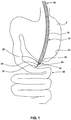
- FIG. 1 depicts an exemplary endoscope 10 performing an exemplary transluminal endoscopic surgery.
- the endoscope 10 may be inserted into the stomach 5 through the esophagus.
- the endoscope 10 may make a puncture 80 through organ wall 70, pass through the puncture 80, and operate at a work site 55.
- the work site 55 could include, for instance, part of the small intestine 50.
- element 10 is described as an endoscope, element 10 could include any device (such as, a catheter, a guide tube, etc.) inserted into the body for diagnostic or therapeutic purposes.
- the endoscope 10 may include an elongate member 15 extending between a proximal end 60 and a distal end 90.
- the proximal end 60 may include the end of the endoscope 10 external to the body and the distal end 90 may include the end of the endoscope 10 internal to the body.
- a plurality of lumens 20 may run longitudinally through the endoscope 10. Lumens 20 may extend between the proximal end 60 external to the body and the distal end 90 internal to the body. In some embodiments, the longitudinal axes of the lumens may run along the longitudinal axes of the endoscope 10.
- Lumens 20 may include one or more of, among others, an aspiration lumen, irrigation lumen, illumination lumen, viewing lumen, and one or more working lumens.
- the illumination lumen may include devices at the distal end configured to illuminate work site 55. These devices may include, among others, bulbs, LEDs, fiber optic cables and light guides.
- the viewing lumen may include devices (such as a CMOS video chip, CCD camera, etc.) at the distal end 90, configured to deliver an image of the work site 55 external to the body.
- the illumination and the viewing lumens may also include cables that may run from the distal end 90 to the proximal end 60.
- the irrigation lumen may be configured to facilitate fluid flow from the proximal end 60 to the distal end 90.
- the proximal end 60 of the irrigation lumen may be attached to a source of fluid, and the distal end 90 may be attached to a nozzle to alter fluid flow.
- the aspiration lumen may be configured to facilitate suction and/or fluid flow through it.
- fluid may flow from the proximal end 60 to the work site 55 through the irrigation lumen. The fluid may then be removed from the work site 55 through the aspiration lumen.
- the aspiration lumen may also be configured to remove biological material along with fluid from the work site 55. For instance, a tissue sample along with fluid (delivered to the work site 55 via the irrigation lumen) may be extracted out of the body through the aspiration lumen or any other lumen configured for this purpose.
- the working lumen may include a hollow cavity configured to deliver an endoscopic instrument 30 to the work site 55.
- the endoscopic instrument 30 may include a therapeutic or diagnostic tool configured to operate at work site 55, while being remotely controlled from outside the body.
- the tool may be configured as an end effector 32 that may be attached at the distal end of the endoscopic instrument 30.
- the working lumen may have any suitable shape, size, and configuration.
- the working lumen may have a substantially circular cross-section, while in other embodiments, the working lumen may be keyed or shaped to accept certain devices.
- a cross-sectional shape of the working lumen may be configured to pass end effector 32 of endoscopic instrument 30 through it.
- Some embodiments of the endoscope may include a plurality of working lumens to deliver multiple tools to the work site 55.
- an endoscopic instrument 30 may also include a mechanism to operate the end effector 32 from outside the body.
- This mechanism may include linkage that connects the end effector 32 to an actuation device (not shown) at the proximal end.
- this linkage may operate the end effector in response to actuation of the actuation device.
- the end effector 32 may include forceps with a pair of jaws rotatably coupled to each other.
- the linkage in this embodiment, may include a pair of cables, each coupled to a jaw of the forceps at the distal end and to the actuation device at the proximal end. Actuation of the actuation device may move one of the cables relative to the other, causing the jaws of the forceps to open and close.
- the end effector 32 may include any medical instrument that may be used in conjunction with a guide tube, catheter, or endoscope 10.
- the end effector 32 may be a purely mechanical instrument (for example, biopsy forceps, baskets, graspers, snares, surgical knifes, needles, suturing instruments, etc.), while in others, the end effector 32 may include electrically driven instruments (for instance, heating elements for cauterizing instruments, etc.), or diagnostic elements (such as sensors, lights, etc.).
- endoscope 10 may be inserted into the body through a natural anatomic opening (such as, mouth, anus, and vagina, etc.).
- a natural anatomic opening such as, mouth, anus, and vagina, etc.
- an endoscopic instrument 30 with, for example, an end effector suitable for puncturing organ wall 70, may be delivered to the distal end 90 of the endoscope 10 via the working lumen.
- the end effector may be used to puncture the organ wall 70.
- the endoscopic tool 30 with the end effector may be withdrawn from the working lumen, and the endoscope 10 inserted in to the organ through the puncture 80.
- an endoscopic instrument 30 with an end effector 32 configured to perform a desired task may be delivered to the work site 55 through the working lumen.
- the desired operations may be performed at the work site 55 using end effector 32. If more than one tool is required to complete the desired task, other desired end effectors 32 may also be delivered to the work site 55.
- endoscope 10 may be retracted from the organ through puncture 80.
- a closure device 40 of the present invention may now be delivered to the puncture 80 via the working lumen. Device 40 may be configured to close puncture 80. As pointed out earlier, although closure device 40 is described as being used to close intentionally created puncture 80, in general, closure device 40 may be used to close any type of opening in body tissue.
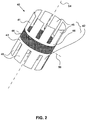
- FIG. 2 illustrates a schematic of an embodiment of device 40 that may be delivered to puncture 80.
- the device 40 may be a multi-component system which includes two end sections 42 coupled together by a midsection 44.
- the two end sections 42 may include a first end section 41 and a second end section 43 (together referred to as the end sections 42).
- the two end sections 42 are substantially similar and symmetric. That is, in the device 40 depicted in FIG. 2 , the first end section 41 is substantially a mirror image of the second end section 43 about a mirror plane 56 normal to a longitudinal axis 54 of device 40.
- the two end sections 42 may not be symmetric, or may be dissimilar.
- the end sections 42 may include anchoring members 46 connected together by a base section 48.
- FIG. 2 illustrates eight anchoring members 46 extending from base section 48, with each anchoring member 46 being shaped substantially like a petal, it is contemplated that anchoring members 46 may have any shape and configuration.
- anchoring members 46 may include any number of extensions, and may have any shape (see for instance, FIG. 9B ).
- the anchoring members in place of discrete anchoring members 46 that extend from base section 48, the anchoring members may be configured differently (such as, for example, baskets depicted in FIG. 9A or mesh-like structures).
- end sections 42 may also include a covering material. The covering material may be draped over a surface of the anchoring members 46, to form an umbrella-like geometry. This covering material may be made of a fabric or other suitable biocompatible materials that may collapse when the end section is in the constrained configuration.
- End sections 42 may be made of any suitable biocompatible material. And, the material of end sections 42 may have any constitutive behavior (such as, for example, elastic, super-elastic, hyper-elastic, plastic, etc.). In some other embodiments, a shape memory alloy (SMA) may be used for end sections 42. These SMAs may include metallic or polymeric materials.
- Non-limiting examples of these SMAs may include alloys of titanium-palladium-nickel, nickel-titanium-copper, gold-cadmium, iron-zinc-copper-aluminum, titanium-niobium-aluminum, iron-manganese-silicon, nickel-titanium, nickel-iron-zinc-aluminum, copper-aluminum-iron, titanium-niobium, etc.
- the end sections 42 may be made of nitinol.
- Each end section 42 may be formed by machining anchoring members 46 from a disk and deforming the anchoring members 46 to a constrained configuration. In some embodiments, this constrained configuration may substantially resemble a tube having a longitudinal axis 54.
- the multiple anchoring members 46 may be constrained in the deformed shape by any external means. For example, device 40 may be inserted into a catheter or a tube that keeps end section 42 constrained in the deformed shape.
- the end sections 42 may be-configured to return to their unconstrained shape when the external force is removed (such as, for instance, when removed from the catheter or the tube). In some embodiments, two end sections 42 may be coupled together with a midsection 44.
- Midsection 44 may have any shape configured to couple the two end sections 42 together.
- the midsection 44 may include a tubular sleeve. This tubular sleeve may be slotted or grooved to make it more flexible and deformable.
- Other configurations of midsection 44 (such as a solid slug, etc.) are also contemplated.
- midsection 44 may have a web-like configuration, or possess sealant-like properties.
- Midsection 44 may be made of a material having a low modulus and/or stiffness to enable midsection 44 to deform easily under compressive force and retain its deformed shape after implantation. In embodiments of midsection 44 with sealant-like properties, these properties may enable the midsection to seal puncture 80.
- the midsection 44 may be constructed of a suitable biocompatible material, that may or may not be biodegradable. In some embodiments, midsection 44 may be made of a fabric. Materials that may be used to construct midsection 44 may include, naturally occurring or synthetic, biostable or biodegradable, and may be selected, for example, from the following, among others: polycarboxylic acid polymers and copolymers including polyacrylic acids; acetal polymers and copolymers; acrylate and methacrylate polymers and copolymers (e.g., n-butyl methacrylate); cellulosic polymers and copolymers, including cellulose acetates, cellulose nitrates, cellulose propionates, cellulose acetate butyrates, cellophanes, rayons, rayon triacetates, and cellulose ethers such as carboxymethyl celluloses and hydroxyalkyl celluloses; polyoxymethylene polymers and copolymers; polyimide polymers and copolymers such as
- polystyrene resins polycaprolactams and polyacrylamides
- resins including alkyd resins, phenolic resins, urea resins, melamine resins, epoxy resins, allyl resins and epoxide resins
- polycarbonates polyacrylonitriles
- polyvinylpyrrolidones cross-linked and otherwise
- styrene-isoprene copolymers e.g., polystyrene-polyisoprene-polystyrene
- acrylonitrile-styrene copolymers acrylonitrile-butadiene-styrene copolymers
- styrene-butadiene copolymers styrene-butadiene copolymers
- styrene-isobutylene copolymers e.g., polyisobutylene-polystyrene block copolymers such as SIBS
- polyvinyl ketones polyvinylcarbazoles
- polyvinyl esters such as polyvinyl acetates
- polybenzimidazoles ionomers
- polyesters including polyethylene terephthalates, polybutylene terephthalates and ali
- biodegradable polymers may be selected from suitable members of the following, among many others: (a) polyester homopolymers and copolymers such as polyglycolide, poly-L-lactide, poly-D-lactide, poly-D,L-lactide, poly(beta-hydroxybutyrate), poiy-D-gluconate, poly-L-gluconate, poly-D,L-gluconate, poiy(epsilon-caprolactone), poly(delta-valerolactone), poly(p-dioxanone), poly(trimethylene carbonate), poly(lactide-co-glycolide), poly(lactide-co-delta-valerolactone), poly(lactide-co-epsilon-caprolactone), poly(L-lactide-co-beta-malic acid), poly(lactide-co-trimethylene carbonate), poly(glycolide-co-trim
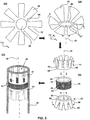
- FIG. 3 illustrates an exemplary method of making device 40.
- End sections 42 may be created from a disk by machining multiple grooves 52 and a central hole 56, in a machining operation 100.
- the machining operation 100 can include any operation known in the art.
- the disk will already include a central hole 56.
- the machining operation 100 may only create the grooves 52. Machining grooves 52 from the disk may create anchoring members 46 joined together by a base section 48.
- the anchoring members 46 may be folded inwards from an initial configuration to a final configuration in a folding operation 200.
- the initial configuration of anchoring members 46 may be an unconstrained configuration in which the anchoring members 46 may be transverse to a longitudinal axis 54 extending through central hole 56.
- the final configuration of the anchoring members 46 may be a constrained configuration in which anchoring members 46 may be substantially parallel to longitudinal axis 54.
- the folding operation 200 may include deforming the multiple anchoring members 46 inwards such that end section 42, post deformation, substantially resembles a tube.
- the folding operation 200 may include any operation configured to deform the anchoring members 46 to the constrained configuration. A mechanical force may be applied to deform the anchoring members 46.
- the end sections 42 may retain their deformed shape (constrained configuration) after the folding operation 200.
- application of energy for example, heat energy
- the anchoring members 46 may return to the unconstrained configuration.
- the anchoring members 46 may spring back to the unconstrained configuration when the deforming force is released.
- a constraining force may be applied to end sections 42 to constrain the anchoring members 46 in the constrained configuration.
- Two end sections 42 may be coupled with midsection 44 in a coupling operation 300, to form the device 40.
- the two end sections 42 may be coupled to the midsection 44 such that the base sections 48 of both end sections 42 abut the midsection 44. In some embodiments, the two end sections 42 are pressed towards each other with the midsection 44 in the middle in the coupling operation 300.
- the end sections 42 may be coupled to the midsection 44 using an adhesive.
- end sections 42 and the midsection 44 may be interference fitted. In these embodiments, the diametrical dimensions of the end sections 42 and the midsection 44 may be such that the end section outer circumference 58 may mate with the midsection inner circumference 62. In some embodiments, the end section inner circumference 66 may mate with the midsection outer circumference 64. It is also contemplated that the two end sections 42 may be coupled with a midsection 44 by other means to form device 40.
- the device 40 may be inserted into a catheter 35 in the insertion operation 400.
- the insertion operation may include placing device 40 in the catheter 35 such that the first end section 41 is proximate an end of catheter 35.
- the longitudinal axes of device 40 and catheter 35 may be substantially collinear, and the end section outer circumference 58 may mate with an internal surface of the catheter 35.
- the internal surface of the catheter 35 may provide the constraining force.
- one or both of the mating surfaces (of end sections and catheter) may be lubricated prior to inserting device 40 in catheter 35.
- the insertion operation 400 may include any manual or automated operation.
- FIG. 4A shows a schematic of the catheter 35 with the inserted device 40 delivered via the working lumen of the endoscope 10.
- the endoscope 10 and the catheter 35 are positioned such that the distal end of the catheter is proximate puncture 80.
- FIG. 4B shows a cross-sectional view of the endoscope 10 and catheter 35. In the description that follows, reference is made to both FIG. 4A and FIG. 4B .
- the catheter 35 may be oriented in the working lumen such that the end of the catheter 35 with the device 40 protrudes from the distal end 90 of the endoscope 10, and the first end section 41 of the device 40 is proximate the puncture 80.
- a push rod 38 may be disposed inside the catheter 35 such that the distal end of the push rod 38 abuts the second end section 43 of the device 40.
- the push rod 38 may be configured to eject the device 40 out the distal end of the catheter 35. In some embodiments, the push rod 38 may eject only part (for example, first end section 41) of the device 40 out of the catheter 35.
- catheter 35 with device 40 is delivered to puncture 80 through a working lumen of endoscope 10, it is contemplated that other means may be used to deliver device 40 to the puncture 80.
- the catheter 35 with the device 40 may be inserted into the body directly through a body cavity.
- push rod 38 illustrated in FIG. 4B as a hollow tube coaxial with catheter 35
- push rod 38 can be a solid tube, a rod, a linkage or any other mechanism that may be configured to eject part (or all) of device 40 out the distal end of the catheter 35.
- push rod 38 may be configured to conduct temperature or current to the device.
- other means may be utilized to deploy device 40 including, but not limited to, pneumatics, hydraulics, pull wires, and screw mechanisms.
- Endoscope 10 may be positioned such that the distal end of the catheter 35 protrudes through puncture 80. While the catheter 35 is thus positioned, the first end section 41 of the device 40 may be ejected out of the catheter 35 by push rod 38 (or any other suitable deployment mechanism). As another example, catheter 35 may be withdrawn relative to device 40 to deploy section 41. In such an embodiment, device 40 may be held stationary by push rod 38 or any other mechanism. Part or all of the midsection 44 may also be ejected along with the first end section 41.
- FIG. 5A shows a schematic of the distal end 90 of the endoscope 10 after the first end section 41 is ejected out of the catheter 35.
- FIG. 5B show a cross-sectional view of the endoscope 10 and catheter 35.
- the anchoring members 46 of the first end section 41 may be configured to unfold when the end section 42 is ejected from of the distal end of the catheter 35.
- the unfolded anchoring members 46 may press against the outer side 70a of organ wall 70.
- anchoring members 46 are being described as opening and pressing against outer wall 70a, it should be noted that, in general, the side of organ wall 70 that the unfolded anchoring members 46 presses against depends upon the direction of approach of endoscope 10. In the unfolded configuration, the anchoring members 46 may substantially return to the initial unconstrained configuration and form a plane intersecting longitudinal axis 54. In some embodiments, the anchoring members 46 may not completely unfold to the initial unconstrained configuration, but may unfold to a configuration between the initial and final configurations.
- FIG. 6 shows the kinked midsection 44 of the device 40 after catheter 35 is rotated (depicted by arrow 85) around longitudinal axis 54.
- the catheter 35 may be rotated multiple times around the longitudinal axis 54 to completely kink midsection 44.
- rotating the catheter 35 may kink and close the cavity through the midsection 44.
- the step of rotating the catheter 35 may be eliminated.
- the catheter 35 may be withdrawn after ejecting the first end section 41.
- midsection 44 may be formed of a material or configuration so that it assumes a twisted, kinked, or like configuration after being ejected from catheter 35.
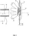
- FIG. 7 shows a schematic illustrating withdrawing of catheter 35.
- Withdrawing the catheter 35 (depicted by arrow 95) may drag the midsection 44 (any part still retained within the catheter 35) along with the second end section 43 out of catheter 35.
- the second end section 43 may also unfold on the inner side 70b of the organ wall 70.
- the second end section 43 may also unfold to the unconstrained configuration.
- midsection 44 may be made of a compliant material that compresses in a longitudinal direction and expands in a transverse direction, when the two end sections 42 press against opposing sides of the organ wall. The expanded midsection 44 may thus help close puncture 80.
- the catheter 35 may be withdrawn from endoscope 10, and the endoscope 10 removed from the body.
- the unfolded end sections 42 of the device 40 along with the midsection 44 may close the puncture 80.
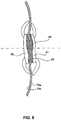
- FIG. 8 shows an illustration of the device 40 closing the puncture 80.
- the unfolded end sections 42 may press against the outer and inner side 70a and 70b of the organ wall 70 with the compressed midsection 44 sealing the puncture 80.
- the covering material may help in closing puncture 80 by promoting tissue growth around the end sections 42.
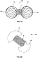
- FIGS. 9A and 9B illustrate two exemplary embodiments of device 40.
- FIG. 9A shows a device 40a in the unconstrained configuration.
- end sections 42a are configured as baskets. In the constrained configuration, these basket shaped end sections 42a may collapse to fit within a catheter.
- Each basket 42a may include a number of wires, threads, or other like members.
- the members may be arranged in any suitable configuration. For example, each member may be helical, straight, or have another shape. These members of may be joined at a corresponding end 42a'.
- FIG. 9B shows another embodiment of device 40b in an unconstrained configuration.
- end sections 42b are shaped as semicircular extensions.
- end sections 42b are illustrated as being semicircular, in other embodiments, end sections 42b may be of any shape or configuration.
- end sections 42b may be circular or may have any other useful geometry.
- these end sections 42b may be folder over (as described with reference to FIG. 3 ) and constrained within a catheter.
- FIG. 10 illustrates an embodiment of the device 40c configured to assist in creating puncture 80 in addition to closing puncture 80.
- the first end section 41 c in this embodiment may be configured as a sharp tip that functions as a trocar or other puncture creating device.
- the second end section 43 may also be configured with the sharp tip (similar to the first end section 41), or it may be configured without the sharp tip (as in the embodiments depicted in FIGS. 2-8 ).
- the catheter 35 with the inserted device 40c may be delivered to the distal end 90 of the endoscope 10 via the working lumen.
- the sharp tip of the first end section 41 c may be pressed against the organ wall 70 to create puncture 80.
- puncture 80 may be closed by deploying device 40c from catheter 35 as described previously.
- the unfolded end sections along with midsection 44 may seal and close the puncture.
- FIG. 11 illustrates another embodiment of device 40d.
- the end section outer circumference 58 may be threaded. It is contemplated that the inner surface of the catheter 35 may also be threaded to mate with the threads on the end section outer circumference 58.
- ejecting the second end section 43d may involve rotating the catheter 35 around the longitudinal axis 54. Rotation of the catheter 35 around the longitudinal axis 54 may advance second end section 43d out of the catheter 35. The ejected device 40d may then close puncture 80 as described previously. Rotating the catheter 35 around the longitudinal axis 54 may also simultaneously kink and close midsection 44 and eject the second end section 43d. The threads on second end section 43d may also enhance gripping of the organ wall.
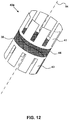
- FIG. 12 illustrates another embodiment of the device 40e.
- the first end section 41 and the second end section 43 may be connected together with an elastic element (such as, a wound spring element 39).
- the spring element 39 may be configured to unwind and rotate end sections 42 with respect to each other (for instance, the first end section 41 with respect to the second end section 43) when released from the catheter 35.
- This relative rotation of the end sections 42 may kink and collapse the tubular midsection 44 upon itself.
- the rotation of the catheter 35 post ejection of the first end section 41 may be eliminated.
- the spring 39 may be eliminated and the second end section 43 may itself be biased to rotate the end section when ejected from the catheter 35. This rotation of the second end section 43 may kink and close the midsection 44.
- biasing the second end section 43 may be accomplished by constructing the second end section 43 with a shape memory alloy or other materials that may be configured to rotate and unfold to an unconstrained configuration upon ejection from the catheter 35.
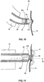
- FIGS. 13A-13C illustrate an embodiment of a puncture closing device 140 that closes a puncture 80 by transforming from a constrained configuration to an unconstrained configuration.
- FIG. 13A illustrates the constrained configuration of the device
- FIG. 13C illustrates the unconstrained configuration.
- the device 140 may possess a tubular configuration having a longitudinal axis 54. From the constrained configuration, the device 140 may contract in the longitudinal direction (indicated by arrows 154) and expand in the transverse direction (indicated by arrows 156) to transform to the unconstrained configuration ( FIG. 13C ) through an interim configuration ( FIG. 13B ).
- the device 140 may possess a substantially planar shape, and may close puncture 80.
- multiple slots 144 may be formed on a tube made of a shape memory alloy.
- the slots 144 may separate strands 142 of the tube connected by opposite base sections 148.
- a cylindrical surface of the device 140 may be covered with a covering material 146.
- this covering material 146 may include a hydrophilic material.
- the covering material 146 may include materials, such as a urethane or a polyester material (for example, Dacron®), that may be configured to have a low stiffness.
- covering 146 may be expandable, such as a foam. This foam may bunch up and form a seal at the opening.
- the device 140 may be subjected to various treatments such that the shape of the device 140 may transform from the constrained configuration to the unconstrained configuration when the device 140 is deployed at the site of the puncture 80.
- Treatments on device 140 may include introducing folds 150 on the strands 142 of the device 140.
- the folds 150 may be created by any mechanical operation. These folds 150 may be configured to act as hinges that may fold different longitudinal sections of the strands 142 on each other. These folds 150 may include a live hinge that separates different sections of the strands 142. In some embodiments, the folds 150 may be created such that the longitudinal location of the folds 150 on each of the strands 142 are substantially the same.
- the device 140 may also be subjected to other treatment, such as heat treatment, that may assist device 140 in remembering a configuration or a shape. These heat treatments may assist device 140 to transform from the constrained configuration to the unconstrained configuration when ejected from a catheter 35. To transform from the constrained configuration to the unconstrained configuration, the strands 142 may fold at the folds 150 (as can be seen in FIGS. 13B and 13C ).
- slots 144 and the strands 142 in the embodiment illustrated in FIGS. 13A-13C are depicted as substantially straight, any configuration of slots 144 and strands 142 may be used with device 140.
- the strands 142 may be curved, tapered, curvilinear, or helically shaped.
- the folds 150 on different strands 142 may be located such that, after transforming to the unconstrained configuration, the folded strands form an interweaving pattern closing the puncture 80.
- the interweaving pattern of the folded strands may make the covering material 146 redundant, and therefore, be eliminated.
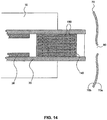
- the device 140 of these embodiments may be inserted into a catheter 35 in the constrained configuration and delivered to the site of a puncture 80 through the working lumen of an endoscope, as illustrated in FIG. 14 .
- the device 140 may be ejected at the site of puncture 80 using push rod 38.
- device 140 may transform to the unconstrained configuration to close puncture 80.
- the covering material 146 may assist in the closing of puncture 80, by hastening tissue growth over the puncture 80.
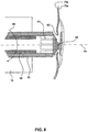
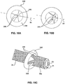
- FIG. 15 illustrates another embodiment of a puncture closing device 240 that may be configured to close puncture 80.
- the puncture closing device 240 of this embodiment may be delivered to the work site 55 external to the catheter.
- the catheter 35a in this embodiment, may include a plurality of vacuum lumens 21 along a periphery and a central lumen 23 running longitudinally through the center of the catheter 35a.
- the device 240 may be loaded on an external surface 34 of the catheter 35a.
- the device 240 of this embodiment may include a plurality of anchoring members 246 deformed from an unconstrained configuration to a constrained configuration.
- the anchoring members 246 When ejected from the catheter 35a, the anchoring members 246 may be configured to transform back to the unconstrained configuration. While transforming back to the unconstrained configuration, the tips 245 of the anchoring members 246 may converge on longitudinal axis 54. While converging, sections of organ wall 70 around puncture 80 may be trapped between anchoring members 246, thereby closing the puncture 80. The puncture 80 may be closed by pinching the organ walls 70 around the puncture 80 between the multiple anchoring members 246.
- FIGS. 16A-16B illustrate an exemplary method of fabricating device 240.
- a disk may be machined to form multiple anchoring members 246 that are joined together by a base section 248.
- FIG. 16A illustrates the unconstrained configuration of the device 240.
- the multiple anchoring members 246 may form flaps with tips 245 that meet at the longitudinal axis 54 that passes through the center of the disk.
- the multiple anchoring members 246 may then be deformed to a constrained configuration.
- Deforming the anchoring members 246 may include applying a deforming force on the anchoring members 246 to bend the tips 245 of the anchoring members 246 outwards from the longitudinal axis 54.
- the anchoring members 246 in the constrained configuration, substantially resemble a frustum of a cone. In some embodiments, the multiple anchoring members 246 may retain the constrained configuration when the deforming force is released. In other embodiments, a constraining force may be applied to the device 240 to keep the anchoring members 246 in the constrained configuration.
- FIG. 16C illustrates the constrained configuration of device 240.
- the device 240 may be loaded on an external surface 34 of the catheter 35a such that the tips 245 of the anchoring members 246 may rest on the external surface 34 of the catheter 35a.
- interaction of the tips 245 with the external surface 34 may provide the constraining force required to keep the anchoring members 246 in the constrained configuration.
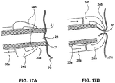
- FIGS. 17A and 17B illustrate a method of using device 240 to create and close puncture 80.
- the catheter 35a may be positioned abutting the region of the organ wall 70 to be punctured.
- FIG. 17A illustrates a schematic of the catheter 35a positioned abutting the organ wall 70.
- a vacuum may be applied through the vacuum lumens 21 of the catheter 35a causing part of the organ wall 70 abutting the catheter 35a to attach to the wall of the catheter 35a.
- a trocar, or other wall puncture device may be advanced through the central lumen 23 to create puncture 80.
- the device 240 may be advanced over the catheter 35a to cause the organ wall 70 around the catheter 35a to stretch, prior to puncturing the organ wall 70. The desired medical procedures may now be performed through the puncture 80.
- FIG. 17B illustrates the closing of puncture 80 post completion of the desired medical procedure.
- the device 240 may be advanced over the catheter 35a using a push rod 38a.
- the push rod 38a of this embodiment may include a hollow tube coaxial with the catheter 35a, located on the external surface 34 of catheter 35a.
- push rod 38a may include other mechanisms, such as a link or a bar, which may advance the device 240 of this embodiment, over the catheter 35a.
- Advancement of the device 240 may allow the anchoring members 246 to return to the unconstrained configuration.
- the vacuum through the vacuum lumens 21 may also be deactivated (or decreased) to release the organ wall 70 adhered to the wall of the catheter 35a.
- the motion of the anchoring members 246 back to the unconstrained configuration may force a part of the organ wall 70 surrounding the puncture 80 to collapse around the puncture 80.
- the device 240 may be advanced over the catheter 35a until the device 240 slips off the catheter 35a.
- the part of the organ wall 70 between the anchoring members 246 may now pinch the puncture 80 shut.
- the device may be part of the push rod.
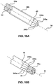
- FIGS. 18A and 18B illustrate an embodiment in which the device 240a is part of the push rod 38b.
- the anchoring members 246a may be constructed from a closed end at the distal end of the push rod 38b.
- positioning the push rod 38b on the external surface 34 of the catheter 35a may force the tips 245 of the anchoring members 246a outwards from the longitudinal axis 54 to form the constrained configuration.
- the external surface 34 of the catheter 35a may further constrain the anchoring members 246a in the constrained configuration.
- a portion of the push rod distal end that demarcates the device section from the rest of the push rod 38b may also include a region of reduced strength.
- This reduced strength region may be configured to separate the device 240a from the rest of the push rod 38b.
- the reduced strength region may include perforations 49, slots, or grooves on the push rod 38b. It is contemplated that the reduced strength region may include other features that are configured to separate on the application of a force. These features may include detachment mechanisms such as hooks, snapping parts, filaments, etc., that may separate the device from the push rod.
- Advancing the push rod 38b over the catheter 35a may cause the anchoring members 246a to slip off the distal end of the catheter 35a.
- the slipping of the anchoring members 246a off the catheter 45a may release the constraining force on the anchoring members 246a causing them to return to their unconstrained configuration.
- the release of the constraining force combined with the motion of the anchoring members 246a to the unconstrained configuration may provide the force needed to separate the device 240a from the push rod 38b.
- the motion of the anchoring members 246a back to the unconstrained configuration may also pinch the organ wall 70 around the puncture 80 shut, as in the previous embodiment.
Landscapes
- Health & Medical Sciences (AREA)
- Life Sciences & Earth Sciences (AREA)
- Surgery (AREA)
- Animal Behavior & Ethology (AREA)
- Public Health (AREA)
- Engineering & Computer Science (AREA)
- Biomedical Technology (AREA)
- Heart & Thoracic Surgery (AREA)
- Medical Informatics (AREA)
- Molecular Biology (AREA)
- Veterinary Medicine (AREA)
- General Health & Medical Sciences (AREA)
- Nuclear Medicine, Radiotherapy & Molecular Imaging (AREA)
- Physics & Mathematics (AREA)
- Biophysics (AREA)
- Optics & Photonics (AREA)
- Pathology (AREA)
- Radiology & Medical Imaging (AREA)
- Cardiology (AREA)
- Surgical Instruments (AREA)
- Devices For Medical Bathing And Washing (AREA)
Abstract
Description
- This application claims the benefit of priority of
U.S. Provisional Application No. 61/129,812 filed on July 21, 2008 U.S. Application No. 12/453,693 filed on May 19, 2009 - Embodiments of the present invention relate to devices to close openings in body tissue. In particular, embodiments of the present invention relate to devices that may be used to close openings in tissue within a body, related methods of closing such openings, and methods of manufacturing such devices.
- During recent years, a major drive in surgery has been the development and application of minimally invasive approaches to traditional operations. In general surgery, an emphasis has been on laparoscopic techniques, which can now be applied to the majority of intra-abdominal procedures. The resulting reduction in trauma to the abdominal wall has a positive impact on patients undergoing abdominal operations.
- More recently, there has been interest in transluminal endoscopic surgical procedures. In transluminal endoscopic surgery, an endoscope is used to deliberately breach (puncture) the wall of the stomach or other organ to work within the peritoneal cavity. In a transluminal endoscopic surgical procedure, a flexible endoscope (along with the required surgical tools) is inserted into the stomach through a natural anatomic opening. Once the endoscope reaches the stomach, the wall of the stomach is punctured and the endoscope advanced into the abdominal cavity where the remotely controlled surgical tools can be used to perform delicate surgical procedures. When the surgical procedure is completed, the endoscope and the tools are withdrawn through the hole in the stomach and the puncture is dosed.
- Although transluminal endoscopic surgery has tremendous potential in reducing trauma associated with surgical procedures, several important developments should be pursued before these procedures can be widely employed. One development is a safe and effective method of closing the puncture in the stomach wall after the endoscope is retracted from the abdominal cavity. Limitations in the mobility of the endoscope and the surgical tools, introduced via a working channel within the endoscope, makes suturing the stomach wall challenging. Therefore, a method of reliability closing a punctured internal body part (such as, a stomach wall) that can be employed using the limited maneuverability offered by an endoscope is required.
- An embodiment of the invention may include a device for closing an opening in body tissue. The device may include a first end section and a second end section both including one or more anchoring members. Both end sections may be configured to transform in shape from a constrained configuration to an unconstrained configuration. The device may also include a midsection coupled between the end sections. The midsection may have at least one configuration that substantially prevents the flow of fluid therethrough.
- Various embodiments of the invention may include one or more of the following aspects: the constrained configuration may correspond to a collapsed shape of the end sections; the unconstrained configuration may correspond to an expanded shape of the end sections; the end sections may be configured to transform from the constrained configuration to the unconstrained configuration when released from a catheter; the one or more anchoring members may be connected together by a base; the base of both end sections may abut the midsection; at least one of the end sections may include a covering material; the covering material may be a fabric; the midsection may be configured to transform from a first configuration to the at least one configuration, wherein the first configuration may correspond to a shape of the midsection when the device is constrained and the at least one configuration may correspond to a shape of the midsection when unconstrained; the midsection may be configured to transform from the first configuration to the at least one configuration by twisting; the midsection may be configured to transform from the first configuration to the at least one configuration when the device is released from a catheter; the end sections may be made of one of an elastic material and a shape memory alloy; at least one of the end sections may substantially resemble a basket; at least one of the end sections may include a plurality of wires and at least some of these wires may be coupled together at opposite ends; the midsection may be made of a fabric; the one or more anchoring members in the constrained configuration may extend along a longitudinal axis; the one or more anchoring members of a distal end section in the constrained configuration may taper towards the longitudinal axis to form a substantially sharp tip; the device may include threads; the device may include an elastic element connecting the first end section and the second end section; the elastic element may be a spring; the elastic element may be configured to twist the midsection to the at least one configuration.
- Another embodiment of the invention may include a method for making a device for closing an opening in body tissue. The method includes creating one or more anchoring members coupled to a base, and deforming the one or more anchoring members to form a first end section in a constrained configuration. The constrained configuration may be a shape in which the one or more anchoring members extend along a longitudinal axis of the device. The method may further include forming a midsection between the first end section and a second end section. The midsection may be configured to transform to a configuration that substantially prevents the flow of fluid therethrough.
- Various embodiments of the invention may include one or more of the following aspects: creating the one or more anchoring members may include forming the one or more anchoring members from a disk; creating the one or more anchoring members may further include forming a central hole in the base; deforming the one or more anchoring members may include bending the one or more anchoring members in a direction towards the longitudinal axis to form the constrained configuration; forming a midsection may include coupling the midsection to a base of the first end section and a base of the second end section; forming a midsection may include coupling the first end section and the second end section to the midsection such that a plane normal to the longitudinal axis and passing through a center of the midsection forms a plane of reflectional symmetry of the device; the midsection may substantially resemble a hollow tube; forming the midsection may include coupling an end face of the midsection to the first end section and an opposite end face of the midsection to the second end section.
- Another embodiment of the invention may include a method of closing an opening in a body tissue. The method may include inserting a catheter containing a closure device at a distal end into a body. The device may include a first end section and a second end section coupled by a midsection. The first end section and the second end section may be constrained configuration within the catheter. The method may also include locating the distal end of the catheter proximate to the opening, and ejecting the first end section out of the catheter such that the first end section transforms from the constrained configuration to an unconstrained configuration on one side of the opening. The method may further include ejecting the second end section out of the catheter to transform the second end section to an unconstrained configuration on an opposite side of the opening, and transforming the midsection to a configuration that substantially closes the opening.
- Various embodiments of the invention may include one or more of the following aspects: the constrained configuration may include constraining anchoring members of the first end section and anchoring members of the second end section; ejecting the first end section may include pushing the first end section out of the catheter; transforming the midsection may include transforming the midsection from an open position to a closed position to close the opening; transforming the midsection may include closing a cavity that passes longitudinally through the midsection; transforming the midsection may include twisting the midsection to transform the midsection from the open position to the closed position; ejecting the second end section may include retracting the catheter out of the body to force the second end section out of the catheter; a distal end of the first end section may be configured to form a substantially sharp tip; the method may including creating the opening; creating the opening may include pressing the sharp tip against the body tissue; ejecting the second end section may include rotating the catheter about a longitudinal axis of the catheter.
- Another embodiment of the invention may include a device for closing an opening in body tissue. The device may include a tube having opposing end faces, and a plurality of strips separated by slots extending lengthwise between the opposing end faces. The device may also include grooves on the strips positioned transverse to a longitudinal axis of the device. Sections of the strips may be configured to fold along the grooves towards each other when the device is unconstrained.
- Various embodiments of the invention may include one or more of the following aspects: the device may further include a covering material disposed on the tube; the covering material may be a fabric; the covering material may be one of a hydrophilic material, a urethane, and a polyester material; the device may be made of shape memory material; the device may have a substantially tubular configuration when constrained within a catheter; the grooves may be located at substantially the same longitudinal location on each strip; the grooves on a first strip may be longitudinally offset from the groove on a second strip.
- Another embodiment of the invention may include a method of closing an opening in body tissue. The method may include inserting a catheter containing a closure device at a distal end into a body. The device may be in a constrained configuration within the catheter. The method may also include locating the distal end of the catheter proximate to the opening, and deploying the device proximate the opening such that the device transforms from the constrained configuration to an unconstrained configuration to close the puncture. The transformation may include the device contracting along the longitudinal axis and expanding transverse to the longitudinal axis.
- Various embodiments of the invention may include one or more of the following aspects: the unconstrained configuration may be a shape in which the device is substantially planar transverse to the longitudinal axis; deploying the device may include forcing the device out of catheter.
- The accompanying drawings, which are incorporated in and constitute a part of this specification, illustrate embodiments of the invention and together with the description, serve to explain the principles of the invention.
-
FIG. 1 is a schematic view of an endoscope performing an exemplary transluminal endoscopic surgical procedure. -
FIG. 2 is a schematic view of an exemplary device of the current invention for closing a puncture created during the endoscopic surgical procedure ofFIG. 1 . -
FIG. 3 is an illustration of an exemplary method of making the closure device ofFIG. 2 . -
FIG. 4A is a schematic view of the device ofFIG. 2 delivered to a work site internal to the body using a catheter. -
FIG. 4B is a cross-sectional view of the catheter ofFIG. 4A . -
FIG. 5A is a schematic illustration of part of the device being deployed from the catheter ofFIG. 4A at the work site. -
FIG. 5B is a cross-sectional view of the catheter ofFIG. 5A . -
FIG. 6 is a schematic view of the kinked midsection of the device ofFIG. 2 after being deployed at a work site. -
FIG. 7 is a schematic illustration of the catheter ofFIG. 4A being withdrawn after the device is deployed at the work site. -
FIG. 8 is a schematic illustration of the device ofFIG. 2 closing the puncture. -
FIGS. 9A-9B are schematic illustrations of other embodiments of a closure device. -
FIG. 10 is a schematic illustration of another embodiment of a closure device. -
FIG. 11 is a schematic illustration of yet another embodiment of a closure device. -
FIG. 12 is a schematic illustration of a further embodiment of a closure device. -
FIG. 13A is schematic view of another exemplary closure device of the current invention for closing a puncture created during the endoscopic surgical procedure ofFIG. 1 . -
FIG. 13B is a schematic illustration of the transformation of the device ofFIG. 13A to a shape to close the puncture. -
FIG. 13C is a schematic illustration of the transformed shape of the device ofFIG. 13A closing the puncture. -
FIG. 14 is a schematic illustration of the device ofFIG. 13A being delivered to a work site internal to the body. -
FIG. 15 is schematic view of another exemplary device of the current invention for closing a puncture created during the endoscopic surgical procedure ofFIG. 1 . -
FIGS. 16A-16B are schematic illustrations of an exemplary method of making the device ofFIG. 15 . -
FIG. 16C is a schematic illustration of the device ofFIG. 15 loaded on a catheter. -
FIGS. 17A-17B are schematic illustrations of an exemplary method of using the device ofFIG. 15 to create and close a puncture. -
FIGS. 18A-18B are schematic illustrations of an exemplary method of loading the device ofFIG. 15 on a catheter. - Reference will now be made in detail to exemplary embodiments of the invention, examples of which are illustrated in the accompanying drawings. Wherever possible, the same reference numbers will be used throughout the drawings to refer to the same or like parts. In the description that follows, the closure devices of the invention will be described as being used to close a puncture in body tissue created during endoscopic surgery. However, this illustration is exemplary only, and embodiments of closure devices of the current invention may be used to close any openings in body tissue formed in any manner, even naturally occurring defects and openings.
-
FIG. 1 depicts anexemplary endoscope 10 performing an exemplary transluminal endoscopic surgery. Theendoscope 10 may be inserted into thestomach 5 through the esophagus. Theendoscope 10 may make apuncture 80 throughorgan wall 70, pass through thepuncture 80, and operate at awork site 55. Thework site 55 could include, for instance, part of thesmall intestine 50. It should be emphasized that althoughelement 10 is described as an endoscope,element 10 could include any device (such as, a catheter, a guide tube, etc.) inserted into the body for diagnostic or therapeutic purposes. - The
endoscope 10 may include anelongate member 15 extending between aproximal end 60 and adistal end 90. In the configuration depicted inFIG. 1 , theproximal end 60 may include the end of theendoscope 10 external to the body and thedistal end 90 may include the end of theendoscope 10 internal to the body. A plurality oflumens 20 may run longitudinally through theendoscope 10.Lumens 20 may extend between theproximal end 60 external to the body and thedistal end 90 internal to the body. In some embodiments, the longitudinal axes of the lumens may run along the longitudinal axes of theendoscope 10. -
Lumens 20 may include one or more of, among others, an aspiration lumen, irrigation lumen, illumination lumen, viewing lumen, and one or more working lumens. The illumination lumen may include devices at the distal end configured to illuminatework site 55. These devices may include, among others, bulbs, LEDs, fiber optic cables and light guides. The viewing lumen may include devices (such as a CMOS video chip, CCD camera, etc.) at thedistal end 90, configured to deliver an image of thework site 55 external to the body. The illumination and the viewing lumens may also include cables that may run from thedistal end 90 to theproximal end 60. - The irrigation lumen may be configured to facilitate fluid flow from the
proximal end 60 to thedistal end 90. In some embodiments, theproximal end 60 of the irrigation lumen may be attached to a source of fluid, and thedistal end 90 may be attached to a nozzle to alter fluid flow. The aspiration lumen may be configured to facilitate suction and/or fluid flow through it. In some embodiments, fluid may flow from theproximal end 60 to thework site 55 through the irrigation lumen. The fluid may then be removed from thework site 55 through the aspiration lumen. In some embodiments, the aspiration lumen may also be configured to remove biological material along with fluid from thework site 55. For instance, a tissue sample along with fluid (delivered to thework site 55 via the irrigation lumen) may be extracted out of the body through the aspiration lumen or any other lumen configured for this purpose. - The working lumen may include a hollow cavity configured to deliver an
endoscopic instrument 30 to thework site 55. Theendoscopic instrument 30 may include a therapeutic or diagnostic tool configured to operate atwork site 55, while being remotely controlled from outside the body. The tool may be configured as anend effector 32 that may be attached at the distal end of theendoscopic instrument 30. In general, the working lumen may have any suitable shape, size, and configuration. In some embodiments, the working lumen may have a substantially circular cross-section, while in other embodiments, the working lumen may be keyed or shaped to accept certain devices. For instance, a cross-sectional shape of the working lumen may be configured to passend effector 32 ofendoscopic instrument 30 through it. Some embodiments of the endoscope may include a plurality of working lumens to deliver multiple tools to thework site 55. - In addition to the
end effector 32, anendoscopic instrument 30 may also include a mechanism to operate theend effector 32 from outside the body. This mechanism may include linkage that connects theend effector 32 to an actuation device (not shown) at the proximal end. In some embodiments, this linkage may operate the end effector in response to actuation of the actuation device. For example, in some embodiments, theend effector 32 may include forceps with a pair of jaws rotatably coupled to each other. The linkage, in this embodiment, may include a pair of cables, each coupled to a jaw of the forceps at the distal end and to the actuation device at the proximal end. Actuation of the actuation device may move one of the cables relative to the other, causing the jaws of the forceps to open and close. - The
end effector 32 may include any medical instrument that may be used in conjunction with a guide tube, catheter, orendoscope 10. In some embodiments, theend effector 32 may be a purely mechanical instrument (for example, biopsy forceps, baskets, graspers, snares, surgical knifes, needles, suturing instruments, etc.), while in others, theend effector 32 may include electrically driven instruments (for instance, heating elements for cauterizing instruments, etc.), or diagnostic elements (such as sensors, lights, etc.). - In the exemplary transluminal endoscopic surgery illustrated in
FIG. 1 ,endoscope 10 may be inserted into the body through a natural anatomic opening (such as, mouth, anus, and vagina, etc.). When thedistal end 90 of theendoscope 10 is proximate to an internal surface (such as, an internal organ wall 70), anendoscopic instrument 30 with, for example, an end effector suitable for puncturingorgan wall 70, may be delivered to thedistal end 90 of theendoscope 10 via the working lumen. The end effector may be used to puncture theorgan wall 70. Onceorgan wall 70 is punctured, theendoscopic tool 30 with the end effector may be withdrawn from the working lumen, and theendoscope 10 inserted in to the organ through thepuncture 80. When thedistal end 90 of theendoscope 10 is positioned at the desiredwork site 55 within the organ (such as, for example intestine 50), anendoscopic instrument 30 with anend effector 32 configured to perform a desired task may be delivered to thework site 55 through the working lumen. - The desired operations may be performed at the
work site 55 usingend effector 32. If more than one tool is required to complete the desired task, other desiredend effectors 32 may also be delivered to thework site 55. After completion of the desired operations,endoscope 10 may be retracted from the organ throughpuncture 80. Aclosure device 40 of the present invention may now be delivered to thepuncture 80 via the working lumen.Device 40 may be configured to closepuncture 80. As pointed out earlier, althoughclosure device 40 is described as being used to close intentionally createdpuncture 80, in general,closure device 40 may be used to close any type of opening in body tissue. -
FIG. 2 illustrates a schematic of an embodiment ofdevice 40 that may be delivered to puncture 80. Thedevice 40 may be a multi-component system which includes twoend sections 42 coupled together by amidsection 44. The twoend sections 42 may include afirst end section 41 and a second end section 43 (together referred to as the end sections 42). In the embodiment of thedevice 40 depicted inFIG. 2 , the twoend sections 42 are substantially similar and symmetric. That is, in thedevice 40 depicted inFIG. 2 , thefirst end section 41 is substantially a mirror image of thesecond end section 43 about amirror plane 56 normal to alongitudinal axis 54 ofdevice 40. However, it is contemplated that, in some embodiments, the twoend sections 42 may not be symmetric, or may be dissimilar. Theend sections 42 may include anchoringmembers 46 connected together by abase section 48. AlthoughFIG. 2 illustrates eight anchoringmembers 46 extending frombase section 48, with each anchoringmember 46 being shaped substantially like a petal, it is contemplated that anchoringmembers 46 may have any shape and configuration. In general, anchoringmembers 46 may include any number of extensions, and may have any shape (see for instance,FIG. 9B ). In some embodiments, in place ofdiscrete anchoring members 46 that extend frombase section 48, the anchoring members may be configured differently (such as, for example, baskets depicted inFIG. 9A or mesh-like structures). In some embodiments,end sections 42 may also include a covering material. The covering material may be draped over a surface of the anchoringmembers 46, to form an umbrella-like geometry. This covering material may be made of a fabric or other suitable biocompatible materials that may collapse when the end section is in the constrained configuration. -
End sections 42 may be made of any suitable biocompatible material. And, the material ofend sections 42 may have any constitutive behavior (such as, for example, elastic, super-elastic, hyper-elastic, plastic, etc.). In some other embodiments, a shape memory alloy (SMA) may be used forend sections 42. These SMAs may include metallic or polymeric materials. Non-limiting examples of these SMAs may include alloys of titanium-palladium-nickel, nickel-titanium-copper, gold-cadmium, iron-zinc-copper-aluminum, titanium-niobium-aluminum, iron-manganese-silicon, nickel-titanium, nickel-iron-zinc-aluminum, copper-aluminum-iron, titanium-niobium, etc. In some embodiments, theend sections 42 may be made of nitinol. - Each
end section 42 may be formed by machining anchoringmembers 46 from a disk and deforming the anchoringmembers 46 to a constrained configuration. In some embodiments, this constrained configuration may substantially resemble a tube having alongitudinal axis 54. In some embodiments, themultiple anchoring members 46 may be constrained in the deformed shape by any external means. For example,device 40 may be inserted into a catheter or a tube that keepsend section 42 constrained in the deformed shape. Theend sections 42 may be-configured to return to their unconstrained shape when the external force is removed (such as, for instance, when removed from the catheter or the tube). In some embodiments, twoend sections 42 may be coupled together with amidsection 44. -
Midsection 44 may have any shape configured to couple the twoend sections 42 together. In some embodiments, themidsection 44 may include a tubular sleeve. This tubular sleeve may be slotted or grooved to make it more flexible and deformable. Other configurations of midsection 44 (such as a solid slug, etc.) are also contemplated. For instance, in some embodiments,midsection 44 may have a web-like configuration, or possess sealant-like properties.Midsection 44 may be made of a material having a low modulus and/or stiffness to enablemidsection 44 to deform easily under compressive force and retain its deformed shape after implantation. In embodiments ofmidsection 44 with sealant-like properties, these properties may enable the midsection to sealpuncture 80. - The
midsection 44 may be constructed of a suitable biocompatible material, that may or may not be biodegradable. In some embodiments,midsection 44 may be made of a fabric. Materials that may be used to constructmidsection 44 may include, naturally occurring or synthetic, biostable or biodegradable, and may be selected, for example, from the following, among others: polycarboxylic acid polymers and copolymers including polyacrylic acids; acetal polymers and copolymers; acrylate and methacrylate polymers and copolymers (e.g., n-butyl methacrylate); cellulosic polymers and copolymers, including cellulose acetates, cellulose nitrates, cellulose propionates, cellulose acetate butyrates, cellophanes, rayons, rayon triacetates, and cellulose ethers such as carboxymethyl celluloses and hydroxyalkyl celluloses; polyoxymethylene polymers and copolymers; polyimide polymers and copolymers such as polyether block imides, polyamidimides, polyesterimides, and polyetherimides; polysulfone polymers and copolymers including polyarylsulfones and polyethersulfones; polyamide polymers and copolymers including nylon 6,6, nylon 12, polyether-block co-polyamide polymers (e.g., Pebax.RTM. resins), polycaprolactams and polyacrylamides; resins including alkyd resins, phenolic resins, urea resins, melamine resins, epoxy resins, allyl resins and epoxide resins; polycarbonates; polyacrylonitriles; polyvinylpyrrolidones (cross-linked and otherwise); polymers and copolymers of vinyl monomers including polyvinyl alcohols, polyvinyl halides such as polyvinyl chlorides, ethylene-vinylacetate copolymers (EVA), polyvinylidene chlorides, polyvinyl ethers such as polyvinyl methyl ethers, vinyl aromatic polymers and copolymers such as polystyrenes, styrene-maleic anhydride copolymers, vinyl aromatic-hydrocarbon copolymers including styrene-butadiene copolymers, styrene-ethylene-butylene copolymers (e.g., a polystyrene-polyethylene/butylene-polystyrene (SEBS) copolymer, available as Kraton.RTM. G series polymers), styrene-isoprene copolymers (e.g., polystyrene-polyisoprene-polystyrene), acrylonitrile-styrene copolymers, acrylonitrile-butadiene-styrene copolymers, styrene-butadiene copolymers and styrene-isobutylene copolymers (e.g., polyisobutylene-polystyrene block copolymers such as SIBS), polyvinyl ketones, polyvinylcarbazoles, and polyvinyl esters such as polyvinyl acetates; polybenzimidazoles; ionomers; polyalkyl oxide polymers and copolymers including polyethylene oxides (PEO); polyesters including polyethylene terephthalates, polybutylene terephthalates and aliphatic polyesters such as polymers and copolymers of lactide (which includes lactic acid as well as d-,I- and meso lactide), epsilon-caprolactone, glycolide (including glycolic acid), hydroxybutyrate, hydroxyvalerate, para-dioxanone, trimethylene carbonate (and its alkyl derivatives), 1,4-dioxepan-2-one, 1,5-dioxepan-2-one, and 6,6-dimethyl-1,4-dioxan-2-one (a copolymer of polylactic acid and polycaprolactone is one specific example); polyether polymers and copolymers including polyarylethers such as polyphenylene ethers, polyether ketones, polyether ether ketones; polyphenylene sulfides; polyisocyanates; polyolefin polymers and copolymers, including polyalkylenes such as polypropylenes, polyethylenes (low and high density, low and high molecular weight), polybutylenes (such as polybut-1-ene and polyisobutylene), polyolefin elastomers (e.g., santoprene), ethylene propylene diene monomer (EPDM) rubbers, poly-4-methyl-pen-1-enes, ethylene-alpha-olefin copolymers, ethylene-methyl methacrylate copolymers and ethylene-vinyl acetate copolymers; fluorinated polymers and copolymers, including polytetrafluoroethylenes (PTFE), poly(tetrafluoroethylene-co-hexafluoropropene) (FEP), modified ethylene-tetrafluoroethylene copolymers (ETFE), and polyvinylidene fluorides (PVDF); silicone polymers and copolymers; polyurethanes; p-xylylene polymers; polyiminocarbonates; copoly (ether-esters) such as polyethylene oxide-polylactic acid copolymers; polyphosphazines; polyalkylene oxalates; polyoxaamides and polyoxaesters (including those containing amines and/or amido groups); polyorthoesters; biopolymers, such as polypeptides, proteins, polysaccharides and fatty acids (and esters thereof), including fibrin, fibrinogen, collagen (e.g., collagen IV or V), fibronectin, elastin, chitosan, gelatin, starch, glycosaminoglycans such as hyaluronic acid; as well as blends and further copolymers of the above. - Examples of biodegradable polymers, not necessarily exclusive of those set forth above, may be selected from suitable members of the following, among many others: (a) polyester homopolymers and copolymers such as polyglycolide, poly-L-lactide, poly-D-lactide, poly-D,L-lactide, poly(beta-hydroxybutyrate), poiy-D-gluconate, poly-L-gluconate, poly-D,L-gluconate, poiy(epsilon-caprolactone), poly(delta-valerolactone), poly(p-dioxanone), poly(trimethylene carbonate), poly(lactide-co-glycolide), poly(lactide-co-delta-valerolactone), poly(lactide-co-epsilon-caprolactone), poly(L-lactide-co-beta-malic acid), poly(lactide-co-trimethylene carbonate), poly(glycolide-co-trimethylene carbonate), poly(beta-hydroxybutyrate-co-beta-hydroxyvalerate), poly[1,3-bis(p-carboxyphenoxy)propane-co-sebacic acid], and poly(sebacic acid-co-fumaric acid), among others (b) polyanhydride homopolymers and copolymers such as poly(adipic anhydride), poly(suberic anhydride), poly(sebacic anhydride), poly(dodecanedioic anhydride), poly(maleic anhydride), poly[1,3-bis(p-carboxyphenoxy)methane anhydride], and poly[alpha,omega-bis(p-carboxyphenoxy)alkane anhydrides] such as poly[1,3-bis(p-carboxyphenoxy)propane anhydride] and poly[1,3-bis(p-carboxyphenoxy)hexane anhydride], among others; (c) poly(ortho esters) such as those synthesized by copolymerization of various diketene acetals and diols, and (d) amino acid based homopolymers and copolymers including tyrosine-based polyarylates (e.g., copolymers of a diphenol and a diacid linked by ester bonds, with diphenols selected, for instance, from ethyl, butyl, hexyl, octyl and bezyl esters of desaminotyrosyl-tyrosine and diacids selected, for instance, from succinic, glutaric, adipic, suberic and sebacic acid), tyrosine-based polycarbonates (e.g., copolymers formed by the condensation polymerization of phosgene and a diphenol selected, for instance, from ethyl, butyl, hexyl, octyl and bezyl esters of desaminotyrosyl-tyrosine, among others), and leucine and lysine-based polyester-amides; specific examples of tyrosine based polymers include poly(desaminotyrosyl-tyrosine-ethyl ester adipate) or poly(DTE adipate), poly(desaminotyrosyl-tyrosine hexyl ester succinate) or poly(DTH succinate), poly(desaminotyrosyl-tyrosine ethyl ester carbonate) or poly(DTE carbonate), poly(desaminotyrosyl-tyrosine butyl ester carbonate) or poly(DTB carbonate), poly(desaminotyrosyl-tyrosine hexyl ester carbonate) or poly(DTH carbonate), and poly(desaminotyrosyl-tyrosine octyl ester carbonate) or poly(DTO carbonate), among others. In some embodiments,
midsection 44 may be constructed of a polyester fiber such as Dacron®. -
FIG. 3 illustrates an exemplary method of makingdevice 40.End sections 42 may be created from a disk by machiningmultiple grooves 52 and acentral hole 56, in amachining operation 100. Themachining operation 100 can include any operation known in the art. In some embodiments, the disk will already include acentral hole 56. In these embodiments, themachining operation 100 may only create thegrooves 52. Machininggrooves 52 from the disk may create anchoringmembers 46 joined together by abase section 48. - The anchoring
members 46 may be folded inwards from an initial configuration to a final configuration in afolding operation 200. The initial configuration of anchoringmembers 46 may be an unconstrained configuration in which theanchoring members 46 may be transverse to alongitudinal axis 54 extending throughcentral hole 56. The final configuration of the anchoringmembers 46 may be a constrained configuration in which anchoringmembers 46 may be substantially parallel tolongitudinal axis 54. Thefolding operation 200 may include deforming themultiple anchoring members 46 inwards such thatend section 42, post deformation, substantially resembles a tube. Thefolding operation 200 may include any operation configured to deform the anchoringmembers 46 to the constrained configuration. A mechanical force may be applied to deform the anchoringmembers 46. In some embodiments, theend sections 42 may retain their deformed shape (constrained configuration) after thefolding operation 200. In these embodiments, application of energy (for example, heat energy) may cause the anchoringmembers 46 to return to the unconstrained configuration. In some embodiments, the anchoringmembers 46 may spring back to the unconstrained configuration when the deforming force is released. In these embodiments, a constraining force may be applied to endsections 42 to constrain the anchoringmembers 46 in the constrained configuration. - Two
end sections 42 may be coupled withmidsection 44 in acoupling operation 300, to form thedevice 40. The twoend sections 42 may be coupled to themidsection 44 such that thebase sections 48 of bothend sections 42 abut themidsection 44. In some embodiments, the twoend sections 42 are pressed towards each other with themidsection 44 in the middle in thecoupling operation 300. In some embodiments, theend sections 42 may be coupled to themidsection 44 using an adhesive. In some embodiments,end sections 42 and themidsection 44 may be interference fitted. In these embodiments, the diametrical dimensions of theend sections 42 and themidsection 44 may be such that the end sectionouter circumference 58 may mate with the midsectioninner circumference 62. In some embodiments, the end sectioninner circumference 66 may mate with the midsectionouter circumference 64. It is also contemplated that the twoend sections 42 may be coupled with amidsection 44 by other means to formdevice 40. - The
device 40 may be inserted into acatheter 35 in theinsertion operation 400. The insertion operation may include placingdevice 40 in thecatheter 35 such that thefirst end section 41 is proximate an end ofcatheter 35. In the inserted configuration, the longitudinal axes ofdevice 40 andcatheter 35 may be substantially collinear, and the end sectionouter circumference 58 may mate with an internal surface of thecatheter 35. In embodiments where a constraining force retains the anchoringmembers 46 in the constrained configuration, the internal surface of thecatheter 35 may provide the constraining force. In some embodiments, one or both of the mating surfaces (of end sections and catheter) may be lubricated prior to insertingdevice 40 incatheter 35. Theinsertion operation 400 may include any manual or automated operation. -
Catheter 35 with the inserteddevice 40 may be delivered to puncture 80 via a working lumen ofendoscope 10.FIG. 4A shows a schematic of thecatheter 35 with the inserteddevice 40 delivered via the working lumen of theendoscope 10. In the schematic depicted inFIG. 4A , theendoscope 10 and thecatheter 35 are positioned such that the distal end of the catheter isproximate puncture 80.FIG. 4B shows a cross-sectional view of theendoscope 10 andcatheter 35. In the description that follows, reference is made to bothFIG. 4A and FIG. 4B . Thecatheter 35 may be oriented in the working lumen such that the end of thecatheter 35 with thedevice 40 protrudes from thedistal end 90 of theendoscope 10, and thefirst end section 41 of thedevice 40 is proximate thepuncture 80. Apush rod 38 may be disposed inside thecatheter 35 such that the distal end of thepush rod 38 abuts thesecond end section 43 of thedevice 40. Thepush rod 38 may be configured to eject thedevice 40 out the distal end of thecatheter 35. In some embodiments, thepush rod 38 may eject only part (for example, first end section 41) of thedevice 40 out of thecatheter 35. - Although in the description above,
catheter 35 withdevice 40 is delivered to puncture 80 through a working lumen ofendoscope 10, it is contemplated that other means may be used to deliverdevice 40 to thepuncture 80. For instance, thecatheter 35 with thedevice 40 may be inserted into the body directly through a body cavity. Additionally, push rod 38 (illustrated inFIG. 4B as a hollow tube coaxial with catheter 35) may have other configurations. For instance, pushrod 38 can be a solid tube, a rod, a linkage or any other mechanism that may be configured to eject part (or all) ofdevice 40 out the distal end of thecatheter 35. In some embodiments, pushrod 38 may be configured to conduct temperature or current to the device. It is also contemplated that other means may be utilized to deploydevice 40 including, but not limited to, pneumatics, hydraulics, pull wires, and screw mechanisms. -
Endoscope 10 may be positioned such that the distal end of thecatheter 35 protrudes throughpuncture 80. While thecatheter 35 is thus positioned, thefirst end section 41 of thedevice 40 may be ejected out of thecatheter 35 by push rod 38 (or any other suitable deployment mechanism). As another example,catheter 35 may be withdrawn relative todevice 40 to deploysection 41. In such an embodiment,device 40 may be held stationary bypush rod 38 or any other mechanism. Part or all of themidsection 44 may also be ejected along with thefirst end section 41. -
FIG. 5A shows a schematic of thedistal end 90 of theendoscope 10 after thefirst end section 41 is ejected out of thecatheter 35.FIG. 5B show a cross-sectional view of theendoscope 10 andcatheter 35. In the description that follows, reference is made to bothFIG. 5A and FIG. 5B . The anchoringmembers 46 of thefirst end section 41 may be configured to unfold when theend section 42 is ejected from of the distal end of thecatheter 35. The unfolded anchoringmembers 46 may press against theouter side 70a oforgan wall 70. Although anchoringmembers 46 are being described as opening and pressing againstouter wall 70a, it should be noted that, in general, the side oforgan wall 70 that the unfolded anchoringmembers 46 presses against depends upon the direction of approach ofendoscope 10. In the unfolded configuration, the anchoringmembers 46 may substantially return to the initial unconstrained configuration and form a plane intersectinglongitudinal axis 54. In some embodiments, the anchoringmembers 46 may not completely unfold to the initial unconstrained configuration, but may unfold to a configuration between the initial and final configurations. - The
catheter 35 may now be rotated around thelongitudinal axis 54 to twist and kinkmidsection 44, and thecatheter 35 slowly withdrawn frompuncture 80. Twisting and kinkingmidsection 44 may fold parts of themidsection 44 over itself.FIG. 6 shows thekinked midsection 44 of thedevice 40 aftercatheter 35 is rotated (depicted by arrow 85) aroundlongitudinal axis 54. In some embodiments, thecatheter 35 may be rotated multiple times around thelongitudinal axis 54 to completely kinkmidsection 44. In embodiments where themidsection 44 includes a tubular sleeve, rotating thecatheter 35 may kink and close the cavity through themidsection 44. In some embodiments, the step of rotating thecatheter 35 may be eliminated. In these embodiments, thecatheter 35 may be withdrawn after ejecting thefirst end section 41. In some embodiments,midsection 44 may be formed of a material or configuration so that it assumes a twisted, kinked, or like configuration after being ejected fromcatheter 35. - Withdrawing the
catheter 35 frompuncture 80 may include gently pulling thecatheter 35 out of the body through the working lumen of theendoscope 10.FIG. 7 shows a schematic illustrating withdrawing ofcatheter 35. Withdrawing the catheter 35 (depicted by arrow 95) may drag the midsection 44 (any part still retained within the catheter 35) along with thesecond end section 43 out ofcatheter 35. Once out of thecatheter 35, thesecond end section 43 may also unfold on theinner side 70b of theorgan wall 70. As with thefirst end section 41, thesecond end section 43 may also unfold to the unconstrained configuration. In such an embodiment,midsection 44 may be made of a compliant material that compresses in a longitudinal direction and expands in a transverse direction, when the twoend sections 42 press against opposing sides of the organ wall. The expandedmidsection 44 may thus helpclose puncture 80. - Once
device 40 is delivered to puncture 80, thecatheter 35 may be withdrawn fromendoscope 10, and theendoscope 10 removed from the body. The unfoldedend sections 42 of thedevice 40 along with themidsection 44 may close thepuncture 80.FIG. 8 shows an illustration of thedevice 40 closing thepuncture 80. The unfoldedend sections 42 may press against the outer andinner side organ wall 70 with thecompressed midsection 44 sealing thepuncture 80. In embodiments ofdevice 40 with a covering material onend sections 42, the covering material may help in closingpuncture 80 by promoting tissue growth around theend sections 42. - Other embodiments of the device may include
end sections 42 andmidsection 44 configured differently than those described inFIGS. 2-8 .FIGS. 9A and 9B illustrate two exemplary embodiments ofdevice 40.FIG. 9A shows adevice 40a in the unconstrained configuration. Indevice 40a ofFIG. 9A ,end sections 42a are configured as baskets. In the constrained configuration, these basket shapedend sections 42a may collapse to fit within a catheter. Eachbasket 42a may include a number of wires, threads, or other like members. The members may be arranged in any suitable configuration. For example, each member may be helical, straight, or have another shape. These members of may be joined at acorresponding end 42a'. -
FIG. 9B shows another embodiment ofdevice 40b in an unconstrained configuration. In the embodiment ofFIG. 9B ,end sections 42b are shaped as semicircular extensions. Althoughend sections 42b are illustrated as being semicircular, in other embodiments,end sections 42b may be of any shape or configuration. For instance, in some embodiments,end sections 42b may be circular or may have any other useful geometry. In the constrained configuration, theseend sections 42b may be folder over (as described with reference toFIG. 3 ) and constrained within a catheter. -
FIG. 10 illustrates an embodiment of thedevice 40c configured to assist in creatingpuncture 80 in addition to closingpuncture 80. Thefirst end section 41 c in this embodiment may be configured as a sharp tip that functions as a trocar or other puncture creating device. Thesecond end section 43 may also be configured with the sharp tip (similar to the first end section 41), or it may be configured without the sharp tip (as in the embodiments depicted inFIGS. 2-8 ). In this embodiment, once thedistal end 90 of theendoscope 10 is proximate theorgan wall 70, thecatheter 35 with the inserteddevice 40c may be delivered to thedistal end 90 of theendoscope 10 via the working lumen. The sharp tip of thefirst end section 41 c may be pressed against theorgan wall 70 to createpuncture 80. After performing the desired operations within the body, puncture 80 may be closed by deployingdevice 40c fromcatheter 35 as described previously. As in previous embodiments, the unfolded end sections along withmidsection 44 may seal and close the puncture. -
FIG. 11 illustrates another embodiment ofdevice 40d. In this embodiment, the end sectionouter circumference 58 may be threaded. It is contemplated that the inner surface of thecatheter 35 may also be threaded to mate with the threads on the end sectionouter circumference 58. In this embodiment, ejecting thesecond end section 43d may involve rotating thecatheter 35 around thelongitudinal axis 54. Rotation of thecatheter 35 around thelongitudinal axis 54 may advancesecond end section 43d out of thecatheter 35. The ejecteddevice 40d may then closepuncture 80 as described previously. Rotating thecatheter 35 around thelongitudinal axis 54 may also simultaneously kink andclose midsection 44 and eject thesecond end section 43d. The threads onsecond end section 43d may also enhance gripping of the organ wall. -
FIG. 12 illustrates another embodiment of thedevice 40e. In the embodiment depicted inFIG. 12 , thefirst end section 41 and thesecond end section 43 may be connected together with an elastic element (such as, a wound spring element 39). Thespring element 39 may be configured to unwind and rotateend sections 42 with respect to each other (for instance, thefirst end section 41 with respect to the second end section 43) when released from thecatheter 35. This relative rotation of theend sections 42 may kink and collapse thetubular midsection 44 upon itself. In this embodiment, the rotation of thecatheter 35 post ejection of thefirst end section 41 may be eliminated. - In some embodiments of
device 40e, thespring 39 may be eliminated and thesecond end section 43 may itself be biased to rotate the end section when ejected from thecatheter 35. This rotation of thesecond end section 43 may kink and close themidsection 44. In these embodiments, biasing thesecond end section 43 may be accomplished by constructing thesecond end section 43 with a shape memory alloy or other materials that may be configured to rotate and unfold to an unconstrained configuration upon ejection from thecatheter 35. -
FIGS. 13A-13C illustrate an embodiment of apuncture closing device 140 that closes apuncture 80 by transforming from a constrained configuration to an unconstrained configuration.FIG. 13A illustrates the constrained configuration of the device, andFIG. 13C illustrates the unconstrained configuration. In the constrained configuration, depicted inFIG. 13A , thedevice 140 may possess a tubular configuration having alongitudinal axis 54. From the constrained configuration, thedevice 140 may contract in the longitudinal direction (indicated by arrows 154) and expand in the transverse direction (indicated by arrows 156) to transform to the unconstrained configuration (FIG. 13C ) through an interim configuration (FIG. 13B ). In the unconstrained configuration, thedevice 140 may possess a substantially planar shape, and may closepuncture 80. - In the
device 140 of this embodiment,multiple slots 144 may be formed on a tube made of a shape memory alloy. Theslots 144 may separatestrands 142 of the tube connected byopposite base sections 148. A cylindrical surface of thedevice 140 may be covered with a coveringmaterial 146. In some embodiments, this coveringmaterial 146 may include a hydrophilic material. In other embodiments, the coveringmaterial 146 may include materials, such as a urethane or a polyester material (for example, Dacron®), that may be configured to have a low stiffness. In some embodiments, covering 146 may be expandable, such as a foam. This foam may bunch up and form a seal at the opening. Thedevice 140 may be subjected to various treatments such that the shape of thedevice 140 may transform from the constrained configuration to the unconstrained configuration when thedevice 140 is deployed at the site of thepuncture 80. - Treatments on
device 140 may include introducingfolds 150 on thestrands 142 of thedevice 140. Thefolds 150 may be created by any mechanical operation. Thesefolds 150 may be configured to act as hinges that may fold different longitudinal sections of thestrands 142 on each other. Thesefolds 150 may include a live hinge that separates different sections of thestrands 142. In some embodiments, thefolds 150 may be created such that the longitudinal location of thefolds 150 on each of thestrands 142 are substantially the same. - The
device 140 may also be subjected to other treatment, such as heat treatment, that may assistdevice 140 in remembering a configuration or a shape. These heat treatments may assistdevice 140 to transform from the constrained configuration to the unconstrained configuration when ejected from acatheter 35. To transform from the constrained configuration to the unconstrained configuration, thestrands 142 may fold at the folds 150 (as can be seen inFIGS. 13B and 13C ). - Although the
slots 144 and thestrands 142 in the embodiment illustrated inFIGS. 13A-13C , are depicted as substantially straight, any configuration ofslots 144 andstrands 142 may be used withdevice 140. For example, in some embodiments, thestrands 142 may be curved, tapered, curvilinear, or helically shaped. In some embodiments ofdevice 140, thefolds 150 ondifferent strands 142 may be located such that, after transforming to the unconstrained configuration, the folded strands form an interweaving pattern closing thepuncture 80. In some such embodiments, the interweaving pattern of the folded strands may make the coveringmaterial 146 redundant, and therefore, be eliminated. - The
device 140 of these embodiments may be inserted into acatheter 35 in the constrained configuration and delivered to the site of apuncture 80 through the working lumen of an endoscope, as illustrated inFIG. 14 . As described previously, thedevice 140 may be ejected at the site ofpuncture 80 usingpush rod 38. Upon deployment,device 140 may transform to the unconstrained configuration to closepuncture 80. In the unconstrained configuration, the coveringmaterial 146 may assist in the closing ofpuncture 80, by hastening tissue growth over thepuncture 80. -
FIG. 15 illustrates another embodiment of apuncture closing device 240 that may be configured to closepuncture 80. Unlike the puncture closing devices of previous embodiments that may be delivered to awork site 55 inside a catheter, thepuncture closing device 240 of this embodiment may be delivered to thework site 55 external to the catheter. Thecatheter 35a, in this embodiment, may include a plurality ofvacuum lumens 21 along a periphery and acentral lumen 23 running longitudinally through the center of thecatheter 35a. Thedevice 240 may be loaded on anexternal surface 34 of thecatheter 35a. Thedevice 240 of this embodiment may include a plurality of anchoringmembers 246 deformed from an unconstrained configuration to a constrained configuration. When ejected from thecatheter 35a, the anchoringmembers 246 may be configured to transform back to the unconstrained configuration. While transforming back to the unconstrained configuration, thetips 245 of the anchoringmembers 246 may converge onlongitudinal axis 54. While converging, sections oforgan wall 70 aroundpuncture 80 may be trapped between anchoringmembers 246, thereby closing thepuncture 80. Thepuncture 80 may be closed by pinching theorgan walls 70 around thepuncture 80 between the multiple anchoringmembers 246. -
FIGS. 16A-16B illustrate an exemplary method of fabricatingdevice 240. To fabricatedevice 240, a disk may be machined to form multiple anchoringmembers 246 that are joined together by abase section 248.FIG. 16A illustrates the unconstrained configuration of thedevice 240. In the unconstrained configuration, the multiple anchoringmembers 246 may form flaps withtips 245 that meet at thelongitudinal axis 54 that passes through the center of the disk. As illustrated inFIG. 16B , the multiple anchoringmembers 246 may then be deformed to a constrained configuration. Deforming the anchoringmembers 246 may include applying a deforming force on the anchoringmembers 246 to bend thetips 245 of the anchoringmembers 246 outwards from thelongitudinal axis 54. In some embodiments, in the constrained configuration, the anchoringmembers 246 substantially resemble a frustum of a cone. In some embodiments, the multiple anchoringmembers 246 may retain the constrained configuration when the deforming force is released. In other embodiments, a constraining force may be applied to thedevice 240 to keep the anchoringmembers 246 in the constrained configuration. -
FIG. 16C illustrates the constrained configuration ofdevice 240. In the constrained configuration, thedevice 240 may be loaded on anexternal surface 34 of thecatheter 35a such that thetips 245 of the anchoringmembers 246 may rest on theexternal surface 34 of thecatheter 35a. In this configuration, interaction of thetips 245 with theexternal surface 34 may provide the constraining force required to keep the anchoringmembers 246 in the constrained configuration. -
FIGS. 17A and 17B illustrate a method of usingdevice 240 to create andclose puncture 80. Thecatheter 35a may be positioned abutting the region of theorgan wall 70 to be punctured.FIG. 17A illustrates a schematic of thecatheter 35a positioned abutting theorgan wall 70. A vacuum may be applied through thevacuum lumens 21 of thecatheter 35a causing part of theorgan wall 70 abutting thecatheter 35a to attach to the wall of thecatheter 35a. A trocar, or other wall puncture device, may be advanced through thecentral lumen 23 to createpuncture 80. In some embodiments, thedevice 240 may be advanced over thecatheter 35a to cause theorgan wall 70 around thecatheter 35a to stretch, prior to puncturing theorgan wall 70. The desired medical procedures may now be performed through thepuncture 80. -
FIG. 17B illustrates the closing ofpuncture 80 post completion of the desired medical procedure. Thedevice 240 may be advanced over thecatheter 35a using apush rod 38a. Thepush rod 38a of this embodiment may include a hollow tube coaxial with thecatheter 35a, located on theexternal surface 34 ofcatheter 35a. However, it is also contemplated thatpush rod 38a may include other mechanisms, such as a link or a bar, which may advance thedevice 240 of this embodiment, over thecatheter 35a. Advancement of thedevice 240 may allow the anchoringmembers 246 to return to the unconstrained configuration. The vacuum through thevacuum lumens 21 may also be deactivated (or decreased) to release theorgan wall 70 adhered to the wall of thecatheter 35a. The motion of the anchoringmembers 246 back to the unconstrained configuration may force a part of theorgan wall 70 surrounding thepuncture 80 to collapse around thepuncture 80. Thedevice 240 may be advanced over thecatheter 35a until thedevice 240 slips off thecatheter 35a. The part of theorgan wall 70 between the anchoringmembers 246 may now pinch thepuncture 80 shut. - In some embodiments, the device may be part of the push rod.
FIGS. 18A and 18B illustrate an embodiment in which thedevice 240a is part of thepush rod 38b. As illustrated inFIG. 18A , the anchoringmembers 246a may be constructed from a closed end at the distal end of thepush rod 38b. As illustrated inFIG. 18B , positioning thepush rod 38b on theexternal surface 34 of thecatheter 35a may force thetips 245 of theanchoring members 246a outwards from thelongitudinal axis 54 to form the constrained configuration. Theexternal surface 34 of thecatheter 35a may further constrain theanchoring members 246a in the constrained configuration. A portion of the push rod distal end that demarcates the device section from the rest of thepush rod 38b may also include a region of reduced strength. This reduced strength region may be configured to separate thedevice 240a from the rest of thepush rod 38b. The reduced strength region may includeperforations 49, slots, or grooves on thepush rod 38b. It is contemplated that the reduced strength region may include other features that are configured to separate on the application of a force. These features may include detachment mechanisms such as hooks, snapping parts, filaments, etc., that may separate the device from the push rod. - Advancing the
push rod 38b over thecatheter 35a may cause theanchoring members 246a to slip off the distal end of thecatheter 35a. The slipping of theanchoring members 246a off the catheter 45a may release the constraining force on theanchoring members 246a causing them to return to their unconstrained configuration. The release of the constraining force combined with the motion of theanchoring members 246a to the unconstrained configuration may provide the force needed to separate thedevice 240a from thepush rod 38b. The motion of theanchoring members 246a back to the unconstrained configuration may also pinch theorgan wall 70 around thepuncture 80 shut, as in the previous embodiment. - It will be apparent to those skilled in the art that various modifications and variations can be made in the disclosed systems and processes without departing from the scope of the invention. Other embodiments of the invention will be apparent to those skilled in the art from consideration of the specification and practice of the invention disclosed herein. It is intended that the specification and examples be considered as exemplary only, with a true scope of the invention being indicated by the following claims.
-
- 1. A device for closing an opening in body tissue, comprising:
- a first end section and a second end section both including one or more anchoring members, both end sections being configured to transform in shape from a constrained configuration to an unconstrained configuration; and
- a midsection coupled between the end sections, the midsection having at least one configuration that substantially prevents the flow of fluid therethrough.
- 2. The device of paragraph 1, wherein the constrained configuration corresponds to a collapsed shape of the end sections.
- 3. The device of paragraph 2, wherein the unconstrained configuration corresponds to an expanded shape of the end sections.
- 4. The device of paragraph 3, wherein the end sections are configured to transform from the constrained configuration to the unconstrained configuration when released from a catheter.
- 5. The device of paragraph 1, wherein the one or more anchoring members are connected together by a base.
- 6. The device of
paragraph 5, wherein the base of both end sections abut the midsection. - 7. The device of paragraph 1, wherein at least one of the end sections includes a covering material.
- 8. The device of paragraph 7, wherein the covering material is a fabric.
- 9. The device of paragraph 1, wherein the midsection is configured to transform from a first configuration to the at least one configuration, wherein the first configuration corresponds to a shape of the midsection when the device is constrained and the at least one configuration corresponds to a shape of the midsection when unconstrained.
- 10. The device of paragraph 9, wherein the midsection is configured to transform from the first configuration to the at least one configuration by twisting.
- 11. The device of
paragraph 10, wherein the midsection is configured to transform from the first configuration to the at least one configuration when the device is released from a catheter. - 12. The device of paragraph 1, wherein the end sections are made of one of an elastic material and a shape memory alloy.
- 13. The device of paragraph 1, wherein at least one of the end sections substantially resembles a basket.
- 14. The device of paragraph 1, wherein at least one of the end sections includes a plurality of wires, at least some of the wires being coupled together at opposite ends.
- 15. The device of paragraph 1, wherein the midsection is made of a fabric.
- 16. The device of paragraph 1, wherein the one or more anchoring members in the constrained configuration extend along a longitudinal axis.
- 17. The device of paragraph 1, wherein the one or more anchoring members of a distal end section in the constrained configuration taper towards the longitudinal axis to form a substantially sharp tip.
- 18. The device of paragraph 1, wherein the device includes threads.
- 19. The device of paragraph 1, wherein the device further includes an elastic element connecting the first end section and the second end section.
- 20. The device of paragraph 19, wherein the elastic element is a spring.
- 21. The device of paragraph 19, wherein the elastic element is configured to twist the midsection to the at least one configuration.
- 22. A method for making a device for closing an opening in body tissue comprising:
- creating one or more anchoring members coupled to a base;
- deforming the one or more anchoring members to form a first end section in a constrained configuration, the constrained configuration being a shape in which the one or more anchoring members extend along a longitudinal axis of the device; and
- forming a midsection between the first end section and a second end section, the midsection being configured to transform to a configuration that substantially prevents the flow of fluid therethrough.
- 23. The method of paragraph 22, wherein creating the one or more anchoring members includes forming the one or more anchoring members from a disk.
- 24. The method of paragraph 22, wherein creating the one or more anchoring members further includes forming a central hole in the base.
- 25. The method of paragraph 22, wherein deforming the one or more anchoring members includes bending the one or more anchoring members in a direction towards the longitudinal axis to form the constrained configuration.
- 26. The method of paragraph 22, wherein forming a midsection includes coupling the midsection to a base of the first end section and a base of the second end section.
- 27. The method of paragraph 22, wherein forming a midsection includes coupling the first end section and the second end section to the midsection such that a plane normal to the longitudinal axis and passing through a center of the midsection forms a plane of reflectional symmetry of the device.
- 28. The method of paragraph 22, wherein the midsection substantially resembles a hollow tube.
- 29. The method of paragraph 28, wherein forming a midsection includes coupling an end face of the midsection to the first end section and an opposite end face of the midsection to the second end section.
- 30. A method of closing an opening in a body tissue comprising:
- inserting a catheter containing a closure device at a distal end into a body, the device including a first end section and a second end section coupled by a midsection, the first end section and the second end section being in a constrained configuration within the catheter;
- locating the distal end of the catheter proximate to the opening;
- ejecting the first end section out of the catheter such that the first end section transforms from the constrained configuration to an unconstrained configuration on one side of the opening;
- ejecting the second end section out of the catheter to transform the second end section to an unconstrained configuration on an opposite side of the opening; and
- transforming the midsection to a configuration that substantially closes the opening.
- 31. The method of
paragraph 30, wherein the constrained configuration includes constraining anchoring members of the first end section and anchoring members of the second end section. - 32. The method of
paragraph 30, wherein ejecting the first end section includes pushing the first end section out of the catheter. - 33. The method of
paragraph 30, wherein transforming the midsection includes transforming the midsection from an open position to a closed position to close the opening. - 34. The method of paragraph 33, wherein transforming the midsection includes closing a cavity that passes longitudinally through the midsection.
- 35. The method of paragraph 33, wherein transforming the midsection includes twisting the midsection to transform the midsection from the open position to the closed position.
- 36. The method of
paragraph 30, wherein ejecting the second end section includes retracting the catheter out of the body to force the second end section out of the catheter. - 37. The method of
paragraph 30, wherein a distal end of the first end section is configured to form a substantially sharp tip. - 38. The method of paragraph 37, further including creating the opening.
- 39. The method of
paragraph 38, wherein creating the opening includes pressing the sharp tip against the body tissue. - 40. The method of
paragraph 30, wherein ejecting the second end section includes rotating the catheter about a longitudinal axis of the catheter. - 41. A device for closing an opening in body tissue comprising:
- a tube having opposing end faces;
- a plurality of strips separated by slots extending lengthwise between the opposing end faces; and
- grooves on the strips positioned transverse to a longitudinal axis of the device, wherein sections of the strips are configured to fold along the grooves towards each other when the device is unconstrained.
- 42. The device of
paragraph 41, further including a covering material disposed on the tube. - 43. The device of
paragraph 42, wherein the covering material is a fabric. - 44. The device of
paragraph 42, wherein the covering material is one of a hydrophilic material, a urethane, and a polyester material. - 45. The device of
paragraph 41, wherein the device is made of shape memory material. - 46. The device of
paragraph 41, wherein the device has a substantially tubular configuration when constrained within a catheter. - 47. The device of
paragraph 41, wherein the grooves are located at substantially the same longitudinal location on each strip. - 48. The device of
paragraph 41, wherein the grooves on a first strip are longitudinally offset from the groove on a second strip. - 49. A method of closing an opening in body tissue comprising:
- inserting a catheter containing a closure device at a distal end into a body, the device being in a constrained configuration within the catheter;
- locating the distal end of the catheter proximate to the opening; and
- deploying the device proximate the opening such that the device transforms from the constrained configuration to an unconstrained configuration to close the puncture, wherein the transformation includes the device contracting along the longitudinal axis and expanding transverse to the longitudinal axis.
- 50. The method of
paragraph 49, wherein the unconstrained configuration is a shape in which the device is substantially planar transverse to the longitudinal axis. - 51. The method of
paragraph 49, wherein deploying the device includes forcing the device out of catheter.
Claims (9)
- A device (40) for closing an opening in body tissue, comprising:a first end section (41) and a second end section (43) both including one or more anchoring members (46), and a longitudinal axis (54), both end sections (41, 43) being configured to transform in shape from a constrained configuration to an unconstrained configuration, wherein in the constrained configuration the one or more anchoring members (46) are substantially parallel to the longitudinal axis (54), and in the unconstrained configuration the one or more anchoring members (56) are substantially transverse to the longitudinal axis (54); anda midsection (44) coupled between the end sections (41, 43), the midsection (44) being self-biased to twist into at least one configuration that substantially prevents the flow of fluid therethrough.
- The device of claim 1, wherein the constrained configuration corresponds to a collapsed shape of the end sections (41, 43), and the unconstrained configuration corresponds to an expanded shape of the end sections (41, 43), and wherein the end sections (41, 43) are configured to transform from the constrained configuration to the unconstrained configuration when released from a catheter.
- The device of claim 1, wherein the one or more anchoring members (46) are connected together by a base (48), and the base (48) of both end sections (41, 43) abut the midsection (44).
- The device of claim 1, wherein at least one of the end sections (41, 43) includes a covering material.
- The device of claim 4, wherein the covering material is a fabric.
- The device of claim 1, wherein the midsection (44) is configured to automatically transform from a first configuration to the at least one configuration that substantially prevents the flow of fluid therethrough by automatically twisting when the device is released from a catheter, wherein the first configuration corresponds to a shape of the midsection when the device is constrained and the at least one configuration that substantially prevents the flow of fluid therethrough corresponds to a shape of the midsection (44) when unconstrained.
- The device of claim 1, wherein the end sections (41, 43) are made of one of an elastic material and a shape memory alloy.
- The device of claim 1, wherein the one or more anchoring members (46) of a distal end section in the constrained configuration taper towards the longitudinal axis (54) to form a substantially sharp tip.
- The device of claim 1, wherein the device further includes a spring element (39) connecting the first end section (41) and the second end section (43), and wherein the spring element (39) is inherently biased to cause the midsection (44) to twist into the at least one configuration that substantially prevents the flow of fluid therethrough.
Applications Claiming Priority (4)
| Application Number | Priority Date | Filing Date | Title |
|---|---|---|---|
| US12981208P | 2008-07-21 | 2008-07-21 | |
| US12/453,693 US20100016885A1 (en) | 2008-07-21 | 2009-05-19 | Device to close openings in body tissue |
| EP09790387A EP2317930A2 (en) | 2008-07-21 | 2009-07-14 | Device to close openings in body tissue |
| EP13003385.5A EP2647338B1 (en) | 2008-07-21 | 2009-07-14 | Device to close openings in body tissue |
Related Parent Applications (3)
| Application Number | Title | Priority Date | Filing Date |
|---|---|---|---|
| EP13003385.5A Division-Into EP2647338B1 (en) | 2008-07-21 | 2009-07-14 | Device to close openings in body tissue |
| EP13003385.5A Division EP2647338B1 (en) | 2008-07-21 | 2009-07-14 | Device to close openings in body tissue |
| EP09790387A Division EP2317930A2 (en) | 2008-07-21 | 2009-07-14 | Device to close openings in body tissue |
Publications (1)
| Publication Number | Publication Date |
|---|---|
| EP3187118A1 true EP3187118A1 (en) | 2017-07-05 |
Family
ID=41530972
Family Applications (3)
| Application Number | Title | Priority Date | Filing Date |
|---|---|---|---|
| EP09790387A Withdrawn EP2317930A2 (en) | 2008-07-21 | 2009-07-14 | Device to close openings in body tissue |
| EP13003385.5A Active EP2647338B1 (en) | 2008-07-21 | 2009-07-14 | Device to close openings in body tissue |
| EP17152686.6A Withdrawn EP3187118A1 (en) | 2008-07-21 | 2009-07-14 | Device to close openings in body tissue |
Family Applications Before (2)
| Application Number | Title | Priority Date | Filing Date |
|---|---|---|---|
| EP09790387A Withdrawn EP2317930A2 (en) | 2008-07-21 | 2009-07-14 | Device to close openings in body tissue |
| EP13003385.5A Active EP2647338B1 (en) | 2008-07-21 | 2009-07-14 | Device to close openings in body tissue |
Country Status (6)
| Country | Link |
|---|---|
| US (1) | US20100016885A1 (en) |
| EP (3) | EP2317930A2 (en) |
| JP (2) | JP5816551B2 (en) |
| CA (1) | CA2731223A1 (en) |
| ES (1) | ES2624216T3 (en) |
| WO (1) | WO2010011530A2 (en) |
Families Citing this family (25)
| Publication number | Priority date | Publication date | Assignee | Title |
|---|---|---|---|---|
| US20100081863A1 (en) * | 2008-09-30 | 2010-04-01 | Ethicon Endo-Surgery, Inc. | Methods and devices for performing gastrectomies and gastroplasties |
| EP2525723B1 (en) | 2010-01-20 | 2017-09-20 | Micro Interventional Devices, Inc. | Tissue repair implant and delivery device |
| US10058314B2 (en) | 2010-01-20 | 2018-08-28 | Micro Interventional Devices, Inc. | Tissue closure device and method |
| US10743854B2 (en) | 2010-01-20 | 2020-08-18 | Micro Interventional Devices, Inc. | Tissue closure device and method |
| US10959840B2 (en) | 2010-01-20 | 2021-03-30 | Micro Interventional Devices, Inc. | Systems and methods for affixing a prosthesis to tissue |
| US9980708B2 (en) | 2010-01-20 | 2018-05-29 | Micro Interventional Devices, Inc. | Tissue closure device and method |
| US9526483B2 (en) * | 2010-07-15 | 2016-12-27 | Medtronic Vascular Galway | Apical closure system |
| CN103068319B (en) * | 2010-08-03 | 2016-03-09 | W.L.戈尔及同仁股份有限公司 | Tissue plug |
| CN103269646A (en) * | 2010-10-04 | 2013-08-28 | 约翰·霍普金斯大学 | Method and device for closure of intraluminal perforations |
| US10342548B2 (en) * | 2012-01-13 | 2019-07-09 | W. L. Gore & Associates, Inc. | Occlusion devices and methods of their manufacture and use |
| US10842357B2 (en) * | 2012-10-10 | 2020-11-24 | Moskowitz Family Llc | Endoscopic surgical system |
| US9119948B2 (en) * | 2013-02-20 | 2015-09-01 | Covidien Lp | Occlusive implants for hollow anatomical structures, delivery systems, and related methods |
| US9517014B2 (en) * | 2013-09-16 | 2016-12-13 | Novartis Ag | OCT probe with pivoting fiber |
| US9795366B2 (en) * | 2014-09-18 | 2017-10-24 | Edwards Lifesciences Corporation | Bio-absorbable wound closure device and method |
| WO2016049481A1 (en) * | 2014-09-25 | 2016-03-31 | The Johns Hopkins University | Method and device for closure of intraluminal perforations |
| US10595840B2 (en) | 2015-02-27 | 2020-03-24 | Surgical Innovations Llc | Wound closure apparatus and method |
| US10441259B2 (en) | 2015-02-27 | 2019-10-15 | Surgical Innovations Llc | Wound closure apparatus and method |
| US9615817B2 (en) * | 2015-02-27 | 2017-04-11 | Surgical Innovations Llc | Wound closure apparatus and method |
| US10987129B2 (en) | 2015-09-04 | 2021-04-27 | Medos International Sarl | Multi-shield spinal access system |
| CN113143355A (en) * | 2015-09-04 | 2021-07-23 | 美多斯国际有限公司 | Multi-shield spinal access system |
| US11744447B2 (en) | 2015-09-04 | 2023-09-05 | Medos International | Surgical visualization systems and related methods |
| BR112018010622B1 (en) | 2015-11-25 | 2023-04-11 | Talon Medical, LLC | FABRIC COUPLING DEVICE AND KIT |
| US10722267B2 (en) | 2015-11-30 | 2020-07-28 | Piranha Medical, LLC | Blockage removal |
| US11141177B2 (en) | 2015-11-30 | 2021-10-12 | Piranha Medical Llc | Blockage clearing devices, systems, and methods |
| KR20200126395A (en) | 2018-03-29 | 2020-11-06 | 보스톤 싸이엔티픽 싸이메드 인코포레이티드 | Apparatus, system, and method for pyloric occlusion |
Citations (5)
| Publication number | Priority date | Publication date | Assignee | Title |
|---|---|---|---|---|
| US6355052B1 (en) * | 1996-02-09 | 2002-03-12 | Pfm Produkte Fur Die Medizin Aktiengesellschaft | Device for closure of body defect openings |
| US6391036B1 (en) * | 1998-01-30 | 2002-05-21 | St. Jude Medical Atg Inc. | Medical graft connector or plug structures, and methods of making and installing same |
| US20030153935A1 (en) * | 2000-09-04 | 2003-08-14 | Claude Mialhe | Vascular occlusion device, apparatus and method for using same |
| US20050070934A1 (en) * | 2003-09-30 | 2005-03-31 | Tanaka Don A. | Anastomosis wire ring device |
| US20060058820A1 (en) * | 2002-11-15 | 2006-03-16 | Claude Mialhe | Occlusive device for medical or surgical use |
Family Cites Families (15)
| Publication number | Priority date | Publication date | Assignee | Title |
|---|---|---|---|---|
| US3874388A (en) * | 1973-02-12 | 1975-04-01 | Ochsner Med Found Alton | Shunt defect closure system |
| EP0545091B1 (en) * | 1991-11-05 | 1999-07-07 | The Children's Medical Center Corporation | Occluder for repair of cardiac and vascular defects |
| US5944738A (en) * | 1998-02-06 | 1999-08-31 | Aga Medical Corporation | Percutaneous catheter directed constricting occlusion device |
| US6911032B2 (en) * | 1999-11-18 | 2005-06-28 | Scimed Life Systems, Inc. | Apparatus and method for compressing body tissue |
| US6428548B1 (en) * | 1999-11-18 | 2002-08-06 | Russell F. Durgin | Apparatus and method for compressing body tissue |
| US6623510B2 (en) * | 2000-12-07 | 2003-09-23 | Integrated Vascular Systems, Inc. | Closure device and methods for making and using them |
| US7288105B2 (en) * | 2001-08-01 | 2007-10-30 | Ev3 Endovascular, Inc. | Tissue opening occluder |
| US20070129755A1 (en) * | 2005-12-05 | 2007-06-07 | Ovalis, Inc. | Clip-based systems and methods for treating septal defects |
| US7169167B2 (en) * | 2001-12-04 | 2007-01-30 | Scimed Life Systems, Inc. | Endoscopic apparatus and method |
| US8920442B2 (en) * | 2005-08-24 | 2014-12-30 | Abbott Vascular Inc. | Vascular opening edge eversion methods and apparatuses |
| US8758397B2 (en) * | 2005-08-24 | 2014-06-24 | Abbott Vascular Inc. | Vascular closure methods and apparatuses |
| US20070198057A1 (en) * | 2006-02-21 | 2007-08-23 | Daniel Gelbart | Method and device for closing holes in tissue |
| US7972361B2 (en) * | 2006-06-19 | 2011-07-05 | Cardia, Inc. | Occlusion device with flexible spring connector |
| US20080051830A1 (en) * | 2006-08-24 | 2008-02-28 | Boston Scientific Scimed, Inc. | Occluding device and method |
| US8870914B2 (en) * | 2006-09-12 | 2014-10-28 | Cook Medical Technologies Llc | Medical device and a method for sealing a puncture or an opening |
-
2009
- 2009-05-19 US US12/453,693 patent/US20100016885A1/en not_active Abandoned
- 2009-07-14 CA CA2731223A patent/CA2731223A1/en not_active Abandoned
- 2009-07-14 EP EP09790387A patent/EP2317930A2/en not_active Withdrawn
- 2009-07-14 EP EP13003385.5A patent/EP2647338B1/en active Active
- 2009-07-14 EP EP17152686.6A patent/EP3187118A1/en not_active Withdrawn
- 2009-07-14 WO PCT/US2009/050507 patent/WO2010011530A2/en active Application Filing
- 2009-07-14 ES ES13003385.5T patent/ES2624216T3/en active Active
- 2009-07-14 JP JP2011520092A patent/JP5816551B2/en active Active
-
2013
- 2013-11-14 JP JP2013235630A patent/JP5878155B2/en active Active
Patent Citations (5)
| Publication number | Priority date | Publication date | Assignee | Title |
|---|---|---|---|---|
| US6355052B1 (en) * | 1996-02-09 | 2002-03-12 | Pfm Produkte Fur Die Medizin Aktiengesellschaft | Device for closure of body defect openings |
| US6391036B1 (en) * | 1998-01-30 | 2002-05-21 | St. Jude Medical Atg Inc. | Medical graft connector or plug structures, and methods of making and installing same |
| US20030153935A1 (en) * | 2000-09-04 | 2003-08-14 | Claude Mialhe | Vascular occlusion device, apparatus and method for using same |
| US20060058820A1 (en) * | 2002-11-15 | 2006-03-16 | Claude Mialhe | Occlusive device for medical or surgical use |
| US20050070934A1 (en) * | 2003-09-30 | 2005-03-31 | Tanaka Don A. | Anastomosis wire ring device |
Also Published As
| Publication number | Publication date |
|---|---|
| EP2647338A1 (en) | 2013-10-09 |
| WO2010011530A2 (en) | 2010-01-28 |
| WO2010011530A3 (en) | 2010-03-11 |
| EP2317930A2 (en) | 2011-05-11 |
| EP2647338B1 (en) | 2017-03-01 |
| JP5816551B2 (en) | 2015-11-18 |
| JP5878155B2 (en) | 2016-03-08 |
| CA2731223A1 (en) | 2010-01-28 |
| ES2624216T3 (en) | 2017-07-13 |
| JP2014054561A (en) | 2014-03-27 |
| JP2011528604A (en) | 2011-11-24 |
| US20100016885A1 (en) | 2010-01-21 |
Similar Documents
| Publication | Publication Date | Title |
|---|---|---|
| EP2647338B1 (en) | Device to close openings in body tissue | |
| JP7235811B2 (en) | Device for approximating multiple tissue edges | |
| US9585647B2 (en) | Medical device for repairing a fistula | |
| US7066944B2 (en) | Surgical fastening system | |
| EP2498685B1 (en) | System for providing access and closure to tissue | |
| US10575837B2 (en) | Tissue and vascular closure devices and methods of use thereof | |
| KR101893987B1 (en) | Laparoscopic Surgical Tissue Extraction Device | |
| US20070083231A1 (en) | Vascular closure | |
| WO2009025970A1 (en) | Fistula plugs and apparatuses and methods for fistula plug delivery | |
| JP2013511336A (en) | Device, instrument and method for accessing a body opening | |
| JP2022179677A (en) | Closure device for tissue openings | |
| US20220061847A1 (en) | Grappling systems and methods for lumen apposition or wound defects | |
| US20220133512A1 (en) | Delivery devices for expandable implants and methods therefor |
Legal Events
| Date | Code | Title | Description |
|---|---|---|---|
| PUAI | Public reference made under article 153(3) epc to a published international application that has entered the european phase |
Free format text: ORIGINAL CODE: 0009012 |
|
| STAA | Information on the status of an ep patent application or granted ep patent |
Free format text: STATUS: REQUEST FOR EXAMINATION WAS MADE |
|
| 17P | Request for examination filed |
Effective date: 20170223 |
|
| AC | Divisional application: reference to earlier application |
Ref document number: 2317930 Country of ref document: EP Kind code of ref document: P Ref document number: 2647338 Country of ref document: EP Kind code of ref document: P |
|
| AK | Designated contracting states |
Kind code of ref document: A1 Designated state(s): AT BE BG CH CY CZ DE DK EE ES FI FR GB GR HR HU IE IS IT LI LT LU LV MC MK MT NL NO PL PT RO SE SI SK SM TR |
|
| STAA | Information on the status of an ep patent application or granted ep patent |
Free format text: STATUS: EXAMINATION IS IN PROGRESS |
|
| 17Q | First examination report despatched |
Effective date: 20200130 |
|
| STAA | Information on the status of an ep patent application or granted ep patent |
Free format text: STATUS: EXAMINATION IS IN PROGRESS |
|
| STAA | Information on the status of an ep patent application or granted ep patent |
Free format text: STATUS: THE APPLICATION IS DEEMED TO BE WITHDRAWN |
|
| 18D | Application deemed to be withdrawn |
Effective date: 20230705 |