EP3165305A1 - Surface improvement of additively manufactured articles produced with aluminum alloys - Google Patents
Surface improvement of additively manufactured articles produced with aluminum alloys Download PDFInfo
- Publication number
- EP3165305A1 EP3165305A1 EP16195390.6A EP16195390A EP3165305A1 EP 3165305 A1 EP3165305 A1 EP 3165305A1 EP 16195390 A EP16195390 A EP 16195390A EP 3165305 A1 EP3165305 A1 EP 3165305A1
- Authority
- EP
- European Patent Office
- Prior art keywords
- article
- aluminum alloy
- diffusion
- coating
- diffusion element
- Prior art date
- Legal status (The legal status is an assumption and is not a legal conclusion. Google has not performed a legal analysis and makes no representation as to the accuracy of the status listed.)
- Granted
Links
- 229910000838 Al alloy Inorganic materials 0.000 title claims abstract description 48
- 230000006872 improvement Effects 0.000 title description 11
- 238000009792 diffusion process Methods 0.000 claims abstract description 81
- 238000000034 method Methods 0.000 claims abstract description 81
- 238000000576 coating method Methods 0.000 claims abstract description 53
- 238000004519 manufacturing process Methods 0.000 claims abstract description 52
- 239000011248 coating agent Substances 0.000 claims abstract description 46
- 239000000654 additive Substances 0.000 claims abstract description 28
- 230000000996 additive effect Effects 0.000 claims abstract description 28
- 238000010438 heat treatment Methods 0.000 claims abstract description 7
- 230000008569 process Effects 0.000 claims description 25
- 229910045601 alloy Inorganic materials 0.000 claims description 18
- 239000000956 alloy Substances 0.000 claims description 18
- 238000007747 plating Methods 0.000 claims description 13
- 239000000843 powder Substances 0.000 claims description 13
- PXHVJJICTQNCMI-UHFFFAOYSA-N Nickel Chemical compound [Ni] PXHVJJICTQNCMI-UHFFFAOYSA-N 0.000 claims description 8
- 229910052782 aluminium Inorganic materials 0.000 claims description 8
- XAGFODPZIPBFFR-UHFFFAOYSA-N aluminium Chemical compound [Al] XAGFODPZIPBFFR-UHFFFAOYSA-N 0.000 claims description 8
- 239000011701 zinc Substances 0.000 claims description 8
- 238000002844 melting Methods 0.000 claims description 7
- 230000008018 melting Effects 0.000 claims description 7
- 229910052751 metal Inorganic materials 0.000 claims description 7
- 239000002184 metal Substances 0.000 claims description 7
- HCHKCACWOHOZIP-UHFFFAOYSA-N Zinc Chemical compound [Zn] HCHKCACWOHOZIP-UHFFFAOYSA-N 0.000 claims description 6
- 239000000203 mixture Substances 0.000 claims description 6
- 229910052725 zinc Inorganic materials 0.000 claims description 6
- NWONKYPBYAMBJT-UHFFFAOYSA-L zinc sulfate Chemical compound [Zn+2].[O-]S([O-])(=O)=O NWONKYPBYAMBJT-UHFFFAOYSA-L 0.000 claims description 6
- 229910052759 nickel Inorganic materials 0.000 claims description 4
- 238000007772 electroless plating Methods 0.000 claims description 3
- 238000009713 electroplating Methods 0.000 claims description 3
- 230000004927 fusion Effects 0.000 claims description 3
- PCHJSUWPFVWCPO-UHFFFAOYSA-N gold Chemical compound [Au] PCHJSUWPFVWCPO-UHFFFAOYSA-N 0.000 claims description 3
- 229910052737 gold Inorganic materials 0.000 claims description 3
- 239000010931 gold Substances 0.000 claims description 3
- 238000001513 hot isostatic pressing Methods 0.000 claims description 3
- RYGMFSIKBFXOCR-UHFFFAOYSA-N Copper Chemical compound [Cu] RYGMFSIKBFXOCR-UHFFFAOYSA-N 0.000 claims description 2
- BQCADISMDOOEFD-UHFFFAOYSA-N Silver Chemical compound [Ag] BQCADISMDOOEFD-UHFFFAOYSA-N 0.000 claims description 2
- ATJFFYVFTNAWJD-UHFFFAOYSA-N Tin Chemical compound [Sn] ATJFFYVFTNAWJD-UHFFFAOYSA-N 0.000 claims description 2
- 229910052802 copper Inorganic materials 0.000 claims description 2
- 239000010949 copper Substances 0.000 claims description 2
- 238000010894 electron beam technology Methods 0.000 claims description 2
- 238000000110 selective laser sintering Methods 0.000 claims description 2
- 229910052709 silver Inorganic materials 0.000 claims description 2
- 239000004332 silver Substances 0.000 claims description 2
- 229910052718 tin Inorganic materials 0.000 claims description 2
- 238000000149 argon plasma sintering Methods 0.000 claims 1
- 239000000463 material Substances 0.000 description 33
- 238000005538 encapsulation Methods 0.000 description 17
- 238000012545 processing Methods 0.000 description 13
- 239000000758 substrate Substances 0.000 description 13
- 230000007547 defect Effects 0.000 description 11
- 230000003746 surface roughness Effects 0.000 description 9
- 230000006870 function Effects 0.000 description 6
- 239000000126 substance Substances 0.000 description 6
- 238000013461 design Methods 0.000 description 4
- 238000005516 engineering process Methods 0.000 description 4
- 238000009499 grossing Methods 0.000 description 4
- 238000011282 treatment Methods 0.000 description 4
- 230000009471 action Effects 0.000 description 3
- 239000000470 constituent Substances 0.000 description 3
- 238000000151 deposition Methods 0.000 description 3
- 230000009286 beneficial effect Effects 0.000 description 2
- 238000011960 computer-aided design Methods 0.000 description 2
- 238000005336 cracking Methods 0.000 description 2
- 230000008021 deposition Effects 0.000 description 2
- 238000010586 diagram Methods 0.000 description 2
- 238000007654 immersion Methods 0.000 description 2
- 239000002245 particle Substances 0.000 description 2
- 239000007787 solid Substances 0.000 description 2
- 239000002904 solvent Substances 0.000 description 2
- 239000007921 spray Substances 0.000 description 2
- 229910021578 Iron(III) chloride Inorganic materials 0.000 description 1
- GRYLNZFGIOXLOG-UHFFFAOYSA-N Nitric acid Chemical compound O[N+]([O-])=O GRYLNZFGIOXLOG-UHFFFAOYSA-N 0.000 description 1
- 239000012670 alkaline solution Substances 0.000 description 1
- AZDRQVAHHNSJOQ-UHFFFAOYSA-N alumane Chemical class [AlH3] AZDRQVAHHNSJOQ-UHFFFAOYSA-N 0.000 description 1
- 238000005266 casting Methods 0.000 description 1
- 238000005234 chemical deposition Methods 0.000 description 1
- 229910017052 cobalt Inorganic materials 0.000 description 1
- 239000010941 cobalt Substances 0.000 description 1
- GUTLYIVDDKVIGB-UHFFFAOYSA-N cobalt atom Chemical compound [Co] GUTLYIVDDKVIGB-UHFFFAOYSA-N 0.000 description 1
- 230000007797 corrosion Effects 0.000 description 1
- 238000005260 corrosion Methods 0.000 description 1
- 239000002537 cosmetic Substances 0.000 description 1
- 230000001419 dependent effect Effects 0.000 description 1
- 230000001627 detrimental effect Effects 0.000 description 1
- 238000007598 dipping method Methods 0.000 description 1
- 238000006073 displacement reaction Methods 0.000 description 1
- 230000005496 eutectics Effects 0.000 description 1
- 238000005242 forging Methods 0.000 description 1
- 238000010100 freeform fabrication Methods 0.000 description 1
- 238000005470 impregnation Methods 0.000 description 1
- RBTARNINKXHZNM-UHFFFAOYSA-K iron trichloride Chemical compound Cl[Fe](Cl)Cl RBTARNINKXHZNM-UHFFFAOYSA-K 0.000 description 1
- 238000005304 joining Methods 0.000 description 1
- 238000001465 metallisation Methods 0.000 description 1
- 238000005272 metallurgy Methods 0.000 description 1
- 150000002739 metals Chemical class 0.000 description 1
- 229910017604 nitric acid Inorganic materials 0.000 description 1
- 230000003647 oxidation Effects 0.000 description 1
- 238000007254 oxidation reaction Methods 0.000 description 1
- TWNQGVIAIRXVLR-UHFFFAOYSA-N oxo(oxoalumanyloxy)alumane Chemical compound O=[Al]O[Al]=O TWNQGVIAIRXVLR-UHFFFAOYSA-N 0.000 description 1
- 230000000704 physical effect Effects 0.000 description 1
- 238000005498 polishing Methods 0.000 description 1
- 230000002265 prevention Effects 0.000 description 1
- 238000007712 rapid solidification Methods 0.000 description 1
- 230000009467 reduction Effects 0.000 description 1
- 150000003839 salts Chemical class 0.000 description 1
- 238000012163 sequencing technique Methods 0.000 description 1
- 238000007493 shaping process Methods 0.000 description 1
- 238000007711 solidification Methods 0.000 description 1
- 230000008023 solidification Effects 0.000 description 1
- 239000000243 solution Substances 0.000 description 1
- 230000002123 temporal effect Effects 0.000 description 1
- 239000011135 tin Substances 0.000 description 1
- 239000011800 void material Substances 0.000 description 1
Images


Classifications
-
- B—PERFORMING OPERATIONS; TRANSPORTING
- B22—CASTING; POWDER METALLURGY
- B22F—WORKING METALLIC POWDER; MANUFACTURE OF ARTICLES FROM METALLIC POWDER; MAKING METALLIC POWDER; APPARATUS OR DEVICES SPECIALLY ADAPTED FOR METALLIC POWDER
- B22F3/00—Manufacture of workpieces or articles from metallic powder characterised by the manner of compacting or sintering; Apparatus specially adapted therefor ; Presses and furnaces
- B22F3/12—Both compacting and sintering
- B22F3/14—Both compacting and sintering simultaneously
- B22F3/15—Hot isostatic pressing
-
- B—PERFORMING OPERATIONS; TRANSPORTING
- B22—CASTING; POWDER METALLURGY
- B22F—WORKING METALLIC POWDER; MANUFACTURE OF ARTICLES FROM METALLIC POWDER; MAKING METALLIC POWDER; APPARATUS OR DEVICES SPECIALLY ADAPTED FOR METALLIC POWDER
- B22F10/00—Additive manufacturing of workpieces or articles from metallic powder
-
- B—PERFORMING OPERATIONS; TRANSPORTING
- B22—CASTING; POWDER METALLURGY
- B22F—WORKING METALLIC POWDER; MANUFACTURE OF ARTICLES FROM METALLIC POWDER; MAKING METALLIC POWDER; APPARATUS OR DEVICES SPECIALLY ADAPTED FOR METALLIC POWDER
- B22F3/00—Manufacture of workpieces or articles from metallic powder characterised by the manner of compacting or sintering; Apparatus specially adapted therefor ; Presses and furnaces
- B22F3/10—Sintering only
- B22F3/105—Sintering only by using electric current other than for infrared radiant energy, laser radiation or plasma ; by ultrasonic bonding
-
- B—PERFORMING OPERATIONS; TRANSPORTING
- B22—CASTING; POWDER METALLURGY
- B22F—WORKING METALLIC POWDER; MANUFACTURE OF ARTICLES FROM METALLIC POWDER; MAKING METALLIC POWDER; APPARATUS OR DEVICES SPECIALLY ADAPTED FOR METALLIC POWDER
- B22F3/00—Manufacture of workpieces or articles from metallic powder characterised by the manner of compacting or sintering; Apparatus specially adapted therefor ; Presses and furnaces
- B22F3/24—After-treatment of workpieces or articles
- B22F3/26—Impregnating
-
- B—PERFORMING OPERATIONS; TRANSPORTING
- B23—MACHINE TOOLS; METAL-WORKING NOT OTHERWISE PROVIDED FOR
- B23K—SOLDERING OR UNSOLDERING; WELDING; CLADDING OR PLATING BY SOLDERING OR WELDING; CUTTING BY APPLYING HEAT LOCALLY, e.g. FLAME CUTTING; WORKING BY LASER BEAM
- B23K15/00—Electron-beam welding or cutting
- B23K15/0046—Welding
- B23K15/0086—Welding welding for purposes other than joining, e.g. built-up welding
-
- B—PERFORMING OPERATIONS; TRANSPORTING
- B23—MACHINE TOOLS; METAL-WORKING NOT OTHERWISE PROVIDED FOR
- B23P—METAL-WORKING NOT OTHERWISE PROVIDED FOR; COMBINED OPERATIONS; UNIVERSAL MACHINE TOOLS
- B23P6/00—Restoring or reconditioning objects
- B23P6/04—Repairing fractures or cracked metal parts or products, e.g. castings
- B23P6/045—Repairing fractures or cracked metal parts or products, e.g. castings of turbine components, e.g. moving or stationary blades, rotors, etc.
-
- C—CHEMISTRY; METALLURGY
- C22—METALLURGY; FERROUS OR NON-FERROUS ALLOYS; TREATMENT OF ALLOYS OR NON-FERROUS METALS
- C22C—ALLOYS
- C22C21/00—Alloys based on aluminium
-
- C—CHEMISTRY; METALLURGY
- C23—COATING METALLIC MATERIAL; COATING MATERIAL WITH METALLIC MATERIAL; CHEMICAL SURFACE TREATMENT; DIFFUSION TREATMENT OF METALLIC MATERIAL; COATING BY VACUUM EVAPORATION, BY SPUTTERING, BY ION IMPLANTATION OR BY CHEMICAL VAPOUR DEPOSITION, IN GENERAL; INHIBITING CORROSION OF METALLIC MATERIAL OR INCRUSTATION IN GENERAL
- C23C—COATING METALLIC MATERIAL; COATING MATERIAL WITH METALLIC MATERIAL; SURFACE TREATMENT OF METALLIC MATERIAL BY DIFFUSION INTO THE SURFACE, BY CHEMICAL CONVERSION OR SUBSTITUTION; COATING BY VACUUM EVAPORATION, BY SPUTTERING, BY ION IMPLANTATION OR BY CHEMICAL VAPOUR DEPOSITION, IN GENERAL
- C23C10/00—Solid state diffusion of only metal elements or silicon into metallic material surfaces
- C23C10/28—Solid state diffusion of only metal elements or silicon into metallic material surfaces using solids, e.g. powders, pastes
-
- C—CHEMISTRY; METALLURGY
- C23—COATING METALLIC MATERIAL; COATING MATERIAL WITH METALLIC MATERIAL; CHEMICAL SURFACE TREATMENT; DIFFUSION TREATMENT OF METALLIC MATERIAL; COATING BY VACUUM EVAPORATION, BY SPUTTERING, BY ION IMPLANTATION OR BY CHEMICAL VAPOUR DEPOSITION, IN GENERAL; INHIBITING CORROSION OF METALLIC MATERIAL OR INCRUSTATION IN GENERAL
- C23C—COATING METALLIC MATERIAL; COATING MATERIAL WITH METALLIC MATERIAL; SURFACE TREATMENT OF METALLIC MATERIAL BY DIFFUSION INTO THE SURFACE, BY CHEMICAL CONVERSION OR SUBSTITUTION; COATING BY VACUUM EVAPORATION, BY SPUTTERING, BY ION IMPLANTATION OR BY CHEMICAL VAPOUR DEPOSITION, IN GENERAL
- C23C10/00—Solid state diffusion of only metal elements or silicon into metallic material surfaces
- C23C10/60—After-treatment
-
- C—CHEMISTRY; METALLURGY
- C23—COATING METALLIC MATERIAL; COATING MATERIAL WITH METALLIC MATERIAL; CHEMICAL SURFACE TREATMENT; DIFFUSION TREATMENT OF METALLIC MATERIAL; COATING BY VACUUM EVAPORATION, BY SPUTTERING, BY ION IMPLANTATION OR BY CHEMICAL VAPOUR DEPOSITION, IN GENERAL; INHIBITING CORROSION OF METALLIC MATERIAL OR INCRUSTATION IN GENERAL
- C23C—COATING METALLIC MATERIAL; COATING MATERIAL WITH METALLIC MATERIAL; SURFACE TREATMENT OF METALLIC MATERIAL BY DIFFUSION INTO THE SURFACE, BY CHEMICAL CONVERSION OR SUBSTITUTION; COATING BY VACUUM EVAPORATION, BY SPUTTERING, BY ION IMPLANTATION OR BY CHEMICAL VAPOUR DEPOSITION, IN GENERAL
- C23C18/00—Chemical coating by decomposition of either liquid compounds or solutions of the coating forming compounds, without leaving reaction products of surface material in the coating; Contact plating
- C23C18/16—Chemical coating by decomposition of either liquid compounds or solutions of the coating forming compounds, without leaving reaction products of surface material in the coating; Contact plating by reduction or substitution, e.g. electroless plating
- C23C18/1601—Process or apparatus
- C23C18/1633—Process of electroless plating
- C23C18/1635—Composition of the substrate
- C23C18/1637—Composition of the substrate metallic substrate
-
- C—CHEMISTRY; METALLURGY
- C23—COATING METALLIC MATERIAL; COATING MATERIAL WITH METALLIC MATERIAL; CHEMICAL SURFACE TREATMENT; DIFFUSION TREATMENT OF METALLIC MATERIAL; COATING BY VACUUM EVAPORATION, BY SPUTTERING, BY ION IMPLANTATION OR BY CHEMICAL VAPOUR DEPOSITION, IN GENERAL; INHIBITING CORROSION OF METALLIC MATERIAL OR INCRUSTATION IN GENERAL
- C23C—COATING METALLIC MATERIAL; COATING MATERIAL WITH METALLIC MATERIAL; SURFACE TREATMENT OF METALLIC MATERIAL BY DIFFUSION INTO THE SURFACE, BY CHEMICAL CONVERSION OR SUBSTITUTION; COATING BY VACUUM EVAPORATION, BY SPUTTERING, BY ION IMPLANTATION OR BY CHEMICAL VAPOUR DEPOSITION, IN GENERAL
- C23C18/00—Chemical coating by decomposition of either liquid compounds or solutions of the coating forming compounds, without leaving reaction products of surface material in the coating; Contact plating
- C23C18/16—Chemical coating by decomposition of either liquid compounds or solutions of the coating forming compounds, without leaving reaction products of surface material in the coating; Contact plating by reduction or substitution, e.g. electroless plating
- C23C18/1601—Process or apparatus
- C23C18/1633—Process of electroless plating
- C23C18/1689—After-treatment
-
- C—CHEMISTRY; METALLURGY
- C23—COATING METALLIC MATERIAL; COATING MATERIAL WITH METALLIC MATERIAL; CHEMICAL SURFACE TREATMENT; DIFFUSION TREATMENT OF METALLIC MATERIAL; COATING BY VACUUM EVAPORATION, BY SPUTTERING, BY ION IMPLANTATION OR BY CHEMICAL VAPOUR DEPOSITION, IN GENERAL; INHIBITING CORROSION OF METALLIC MATERIAL OR INCRUSTATION IN GENERAL
- C23C—COATING METALLIC MATERIAL; COATING MATERIAL WITH METALLIC MATERIAL; SURFACE TREATMENT OF METALLIC MATERIAL BY DIFFUSION INTO THE SURFACE, BY CHEMICAL CONVERSION OR SUBSTITUTION; COATING BY VACUUM EVAPORATION, BY SPUTTERING, BY ION IMPLANTATION OR BY CHEMICAL VAPOUR DEPOSITION, IN GENERAL
- C23C18/00—Chemical coating by decomposition of either liquid compounds or solutions of the coating forming compounds, without leaving reaction products of surface material in the coating; Contact plating
- C23C18/16—Chemical coating by decomposition of either liquid compounds or solutions of the coating forming compounds, without leaving reaction products of surface material in the coating; Contact plating by reduction or substitution, e.g. electroless plating
- C23C18/31—Coating with metals
- C23C18/32—Coating with nickel, cobalt or mixtures thereof with phosphorus or boron
-
- C—CHEMISTRY; METALLURGY
- C23—COATING METALLIC MATERIAL; COATING MATERIAL WITH METALLIC MATERIAL; CHEMICAL SURFACE TREATMENT; DIFFUSION TREATMENT OF METALLIC MATERIAL; COATING BY VACUUM EVAPORATION, BY SPUTTERING, BY ION IMPLANTATION OR BY CHEMICAL VAPOUR DEPOSITION, IN GENERAL; INHIBITING CORROSION OF METALLIC MATERIAL OR INCRUSTATION IN GENERAL
- C23C—COATING METALLIC MATERIAL; COATING MATERIAL WITH METALLIC MATERIAL; SURFACE TREATMENT OF METALLIC MATERIAL BY DIFFUSION INTO THE SURFACE, BY CHEMICAL CONVERSION OR SUBSTITUTION; COATING BY VACUUM EVAPORATION, BY SPUTTERING, BY ION IMPLANTATION OR BY CHEMICAL VAPOUR DEPOSITION, IN GENERAL
- C23C18/00—Chemical coating by decomposition of either liquid compounds or solutions of the coating forming compounds, without leaving reaction products of surface material in the coating; Contact plating
- C23C18/16—Chemical coating by decomposition of either liquid compounds or solutions of the coating forming compounds, without leaving reaction products of surface material in the coating; Contact plating by reduction or substitution, e.g. electroless plating
- C23C18/31—Coating with metals
- C23C18/38—Coating with copper
-
- C—CHEMISTRY; METALLURGY
- C23—COATING METALLIC MATERIAL; COATING MATERIAL WITH METALLIC MATERIAL; CHEMICAL SURFACE TREATMENT; DIFFUSION TREATMENT OF METALLIC MATERIAL; COATING BY VACUUM EVAPORATION, BY SPUTTERING, BY ION IMPLANTATION OR BY CHEMICAL VAPOUR DEPOSITION, IN GENERAL; INHIBITING CORROSION OF METALLIC MATERIAL OR INCRUSTATION IN GENERAL
- C23C—COATING METALLIC MATERIAL; COATING MATERIAL WITH METALLIC MATERIAL; SURFACE TREATMENT OF METALLIC MATERIAL BY DIFFUSION INTO THE SURFACE, BY CHEMICAL CONVERSION OR SUBSTITUTION; COATING BY VACUUM EVAPORATION, BY SPUTTERING, BY ION IMPLANTATION OR BY CHEMICAL VAPOUR DEPOSITION, IN GENERAL
- C23C18/00—Chemical coating by decomposition of either liquid compounds or solutions of the coating forming compounds, without leaving reaction products of surface material in the coating; Contact plating
- C23C18/16—Chemical coating by decomposition of either liquid compounds or solutions of the coating forming compounds, without leaving reaction products of surface material in the coating; Contact plating by reduction or substitution, e.g. electroless plating
- C23C18/31—Coating with metals
- C23C18/42—Coating with noble metals
-
- C—CHEMISTRY; METALLURGY
- C25—ELECTROLYTIC OR ELECTROPHORETIC PROCESSES; APPARATUS THEREFOR
- C25D—PROCESSES FOR THE ELECTROLYTIC OR ELECTROPHORETIC PRODUCTION OF COATINGS; ELECTROFORMING; APPARATUS THEREFOR
- C25D5/00—Electroplating characterised by the process; Pretreatment or after-treatment of workpieces
- C25D5/48—After-treatment of electroplated surfaces
-
- F—MECHANICAL ENGINEERING; LIGHTING; HEATING; WEAPONS; BLASTING
- F01—MACHINES OR ENGINES IN GENERAL; ENGINE PLANTS IN GENERAL; STEAM ENGINES
- F01D—NON-POSITIVE DISPLACEMENT MACHINES OR ENGINES, e.g. STEAM TURBINES
- F01D5/00—Blades; Blade-carrying members; Heating, heat-insulating, cooling or antivibration means on the blades or the members
- F01D5/12—Blades
- F01D5/28—Selecting particular materials; Particular measures relating thereto; Measures against erosion or corrosion
- F01D5/288—Protective coatings for blades
-
- B—PERFORMING OPERATIONS; TRANSPORTING
- B22—CASTING; POWDER METALLURGY
- B22F—WORKING METALLIC POWDER; MANUFACTURE OF ARTICLES FROM METALLIC POWDER; MAKING METALLIC POWDER; APPARATUS OR DEVICES SPECIALLY ADAPTED FOR METALLIC POWDER
- B22F10/00—Additive manufacturing of workpieces or articles from metallic powder
- B22F10/20—Direct sintering or melting
- B22F10/25—Direct deposition of metal particles, e.g. direct metal deposition [DMD] or laser engineered net shaping [LENS]
-
- B—PERFORMING OPERATIONS; TRANSPORTING
- B22—CASTING; POWDER METALLURGY
- B22F—WORKING METALLIC POWDER; MANUFACTURE OF ARTICLES FROM METALLIC POWDER; MAKING METALLIC POWDER; APPARATUS OR DEVICES SPECIALLY ADAPTED FOR METALLIC POWDER
- B22F10/00—Additive manufacturing of workpieces or articles from metallic powder
- B22F10/20—Direct sintering or melting
- B22F10/28—Powder bed fusion, e.g. selective laser melting [SLM] or electron beam melting [EBM]
-
- B—PERFORMING OPERATIONS; TRANSPORTING
- B22—CASTING; POWDER METALLURGY
- B22F—WORKING METALLIC POWDER; MANUFACTURE OF ARTICLES FROM METALLIC POWDER; MAKING METALLIC POWDER; APPARATUS OR DEVICES SPECIALLY ADAPTED FOR METALLIC POWDER
- B22F10/00—Additive manufacturing of workpieces or articles from metallic powder
- B22F10/30—Process control
- B22F10/36—Process control of energy beam parameters
-
- B—PERFORMING OPERATIONS; TRANSPORTING
- B22—CASTING; POWDER METALLURGY
- B22F—WORKING METALLIC POWDER; MANUFACTURE OF ARTICLES FROM METALLIC POWDER; MAKING METALLIC POWDER; APPARATUS OR DEVICES SPECIALLY ADAPTED FOR METALLIC POWDER
- B22F10/00—Additive manufacturing of workpieces or articles from metallic powder
- B22F10/60—Treatment of workpieces or articles after build-up
- B22F10/62—Treatment of workpieces or articles after build-up by chemical means
-
- B—PERFORMING OPERATIONS; TRANSPORTING
- B22—CASTING; POWDER METALLURGY
- B22F—WORKING METALLIC POWDER; MANUFACTURE OF ARTICLES FROM METALLIC POWDER; MAKING METALLIC POWDER; APPARATUS OR DEVICES SPECIALLY ADAPTED FOR METALLIC POWDER
- B22F10/00—Additive manufacturing of workpieces or articles from metallic powder
- B22F10/60—Treatment of workpieces or articles after build-up
- B22F10/64—Treatment of workpieces or articles after build-up by thermal means
-
- B—PERFORMING OPERATIONS; TRANSPORTING
- B22—CASTING; POWDER METALLURGY
- B22F—WORKING METALLIC POWDER; MANUFACTURE OF ARTICLES FROM METALLIC POWDER; MAKING METALLIC POWDER; APPARATUS OR DEVICES SPECIALLY ADAPTED FOR METALLIC POWDER
- B22F10/00—Additive manufacturing of workpieces or articles from metallic powder
- B22F10/60—Treatment of workpieces or articles after build-up
- B22F10/66—Treatment of workpieces or articles after build-up by mechanical means
-
- B—PERFORMING OPERATIONS; TRANSPORTING
- B22—CASTING; POWDER METALLURGY
- B22F—WORKING METALLIC POWDER; MANUFACTURE OF ARTICLES FROM METALLIC POWDER; MAKING METALLIC POWDER; APPARATUS OR DEVICES SPECIALLY ADAPTED FOR METALLIC POWDER
- B22F10/00—Additive manufacturing of workpieces or articles from metallic powder
- B22F10/70—Recycling
- B22F10/73—Recycling of powder
-
- B—PERFORMING OPERATIONS; TRANSPORTING
- B22—CASTING; POWDER METALLURGY
- B22F—WORKING METALLIC POWDER; MANUFACTURE OF ARTICLES FROM METALLIC POWDER; MAKING METALLIC POWDER; APPARATUS OR DEVICES SPECIALLY ADAPTED FOR METALLIC POWDER
- B22F12/00—Apparatus or devices specially adapted for additive manufacturing; Auxiliary means for additive manufacturing; Combinations of additive manufacturing apparatus or devices with other processing apparatus or devices
- B22F12/40—Radiation means
- B22F12/49—Scanners
-
- B—PERFORMING OPERATIONS; TRANSPORTING
- B22—CASTING; POWDER METALLURGY
- B22F—WORKING METALLIC POWDER; MANUFACTURE OF ARTICLES FROM METALLIC POWDER; MAKING METALLIC POWDER; APPARATUS OR DEVICES SPECIALLY ADAPTED FOR METALLIC POWDER
- B22F12/00—Apparatus or devices specially adapted for additive manufacturing; Auxiliary means for additive manufacturing; Combinations of additive manufacturing apparatus or devices with other processing apparatus or devices
- B22F12/60—Planarisation devices; Compression devices
- B22F12/63—Rollers
-
- B—PERFORMING OPERATIONS; TRANSPORTING
- B22—CASTING; POWDER METALLURGY
- B22F—WORKING METALLIC POWDER; MANUFACTURE OF ARTICLES FROM METALLIC POWDER; MAKING METALLIC POWDER; APPARATUS OR DEVICES SPECIALLY ADAPTED FOR METALLIC POWDER
- B22F3/00—Manufacture of workpieces or articles from metallic powder characterised by the manner of compacting or sintering; Apparatus specially adapted therefor ; Presses and furnaces
- B22F3/24—After-treatment of workpieces or articles
- B22F2003/247—Removing material: carving, cleaning, grinding, hobbing, honing, lapping, polishing, milling, shaving, skiving, turning the surface
-
- B—PERFORMING OPERATIONS; TRANSPORTING
- B22—CASTING; POWDER METALLURGY
- B22F—WORKING METALLIC POWDER; MANUFACTURE OF ARTICLES FROM METALLIC POWDER; MAKING METALLIC POWDER; APPARATUS OR DEVICES SPECIALLY ADAPTED FOR METALLIC POWDER
- B22F2998/00—Supplementary information concerning processes or compositions relating to powder metallurgy
- B22F2998/10—Processes characterised by the sequence of their steps
-
- B—PERFORMING OPERATIONS; TRANSPORTING
- B22—CASTING; POWDER METALLURGY
- B22F—WORKING METALLIC POWDER; MANUFACTURE OF ARTICLES FROM METALLIC POWDER; MAKING METALLIC POWDER; APPARATUS OR DEVICES SPECIALLY ADAPTED FOR METALLIC POWDER
- B22F5/00—Manufacture of workpieces or articles from metallic powder characterised by the special shape of the product
- B22F5/009—Manufacture of workpieces or articles from metallic powder characterised by the special shape of the product of turbine components other than turbine blades
-
- B—PERFORMING OPERATIONS; TRANSPORTING
- B22—CASTING; POWDER METALLURGY
- B22F—WORKING METALLIC POWDER; MANUFACTURE OF ARTICLES FROM METALLIC POWDER; MAKING METALLIC POWDER; APPARATUS OR DEVICES SPECIALLY ADAPTED FOR METALLIC POWDER
- B22F5/00—Manufacture of workpieces or articles from metallic powder characterised by the special shape of the product
- B22F5/04—Manufacture of workpieces or articles from metallic powder characterised by the special shape of the product of turbine blades
-
- B—PERFORMING OPERATIONS; TRANSPORTING
- B33—ADDITIVE MANUFACTURING TECHNOLOGY
- B33Y—ADDITIVE MANUFACTURING, i.e. MANUFACTURING OF THREE-DIMENSIONAL [3-D] OBJECTS BY ADDITIVE DEPOSITION, ADDITIVE AGGLOMERATION OR ADDITIVE LAYERING, e.g. BY 3-D PRINTING, STEREOLITHOGRAPHY OR SELECTIVE LASER SINTERING
- B33Y10/00—Processes of additive manufacturing
-
- B—PERFORMING OPERATIONS; TRANSPORTING
- B33—ADDITIVE MANUFACTURING TECHNOLOGY
- B33Y—ADDITIVE MANUFACTURING, i.e. MANUFACTURING OF THREE-DIMENSIONAL [3-D] OBJECTS BY ADDITIVE DEPOSITION, ADDITIVE AGGLOMERATION OR ADDITIVE LAYERING, e.g. BY 3-D PRINTING, STEREOLITHOGRAPHY OR SELECTIVE LASER SINTERING
- B33Y99/00—Subject matter not provided for in other groups of this subclass
-
- C—CHEMISTRY; METALLURGY
- C22—METALLURGY; FERROUS OR NON-FERROUS ALLOYS; TREATMENT OF ALLOYS OR NON-FERROUS METALS
- C22C—ALLOYS
- C22C1/00—Making non-ferrous alloys
- C22C1/04—Making non-ferrous alloys by powder metallurgy
- C22C1/0408—Light metal alloys
- C22C1/0416—Aluminium-based alloys
-
- C—CHEMISTRY; METALLURGY
- C23—COATING METALLIC MATERIAL; COATING MATERIAL WITH METALLIC MATERIAL; CHEMICAL SURFACE TREATMENT; DIFFUSION TREATMENT OF METALLIC MATERIAL; COATING BY VACUUM EVAPORATION, BY SPUTTERING, BY ION IMPLANTATION OR BY CHEMICAL VAPOUR DEPOSITION, IN GENERAL; INHIBITING CORROSION OF METALLIC MATERIAL OR INCRUSTATION IN GENERAL
- C23C—COATING METALLIC MATERIAL; COATING MATERIAL WITH METALLIC MATERIAL; SURFACE TREATMENT OF METALLIC MATERIAL BY DIFFUSION INTO THE SURFACE, BY CHEMICAL CONVERSION OR SUBSTITUTION; COATING BY VACUUM EVAPORATION, BY SPUTTERING, BY ION IMPLANTATION OR BY CHEMICAL VAPOUR DEPOSITION, IN GENERAL
- C23C26/00—Coating not provided for in groups C23C2/00 - C23C24/00
-
- F—MECHANICAL ENGINEERING; LIGHTING; HEATING; WEAPONS; BLASTING
- F01—MACHINES OR ENGINES IN GENERAL; ENGINE PLANTS IN GENERAL; STEAM ENGINES
- F01D—NON-POSITIVE DISPLACEMENT MACHINES OR ENGINES, e.g. STEAM TURBINES
- F01D5/00—Blades; Blade-carrying members; Heating, heat-insulating, cooling or antivibration means on the blades or the members
-
- F—MECHANICAL ENGINEERING; LIGHTING; HEATING; WEAPONS; BLASTING
- F05—INDEXING SCHEMES RELATING TO ENGINES OR PUMPS IN VARIOUS SUBCLASSES OF CLASSES F01-F04
- F05D—INDEXING SCHEME FOR ASPECTS RELATING TO NON-POSITIVE-DISPLACEMENT MACHINES OR ENGINES, GAS-TURBINES OR JET-PROPULSION PLANTS
- F05D2230/00—Manufacture
- F05D2230/20—Manufacture essentially without removing material
- F05D2230/22—Manufacture essentially without removing material by sintering
-
- F—MECHANICAL ENGINEERING; LIGHTING; HEATING; WEAPONS; BLASTING
- F05—INDEXING SCHEMES RELATING TO ENGINES OR PUMPS IN VARIOUS SUBCLASSES OF CLASSES F01-F04
- F05D—INDEXING SCHEME FOR ASPECTS RELATING TO NON-POSITIVE-DISPLACEMENT MACHINES OR ENGINES, GAS-TURBINES OR JET-PROPULSION PLANTS
- F05D2230/00—Manufacture
- F05D2230/90—Coating; Surface treatment
-
- Y—GENERAL TAGGING OF NEW TECHNOLOGICAL DEVELOPMENTS; GENERAL TAGGING OF CROSS-SECTIONAL TECHNOLOGIES SPANNING OVER SEVERAL SECTIONS OF THE IPC; TECHNICAL SUBJECTS COVERED BY FORMER USPC CROSS-REFERENCE ART COLLECTIONS [XRACs] AND DIGESTS
- Y02—TECHNOLOGIES OR APPLICATIONS FOR MITIGATION OR ADAPTATION AGAINST CLIMATE CHANGE
- Y02P—CLIMATE CHANGE MITIGATION TECHNOLOGIES IN THE PRODUCTION OR PROCESSING OF GOODS
- Y02P10/00—Technologies related to metal processing
- Y02P10/25—Process efficiency
Definitions
- the present disclosure generally relates to additive manufacturing technologies. More particularly, the present disclosure relates to surface improvement of additively manufactured articles produced with aluminum alloys.
- AM additive manufacturing
- DMLF Direct Laser Metal Fusion
- justification for required surface improvement, encapsulation, and subsequent hot isostatic press (HIP) processing extends to various metallurgical reasons including 1) smoothing undesirable surface roughness, 2) smoothing roughness to enable subsequent encapsulation of surface connected porosity and defects for HIP processing to eliminate internal and surface defects in the AM component, 3) removal of metallurgical surface defects such as micro cracking, and 4) being able to predicatively remove excess stock or non-conforming layers without creating metallurgical issues.
- HIP hot isostatic press
- U.S. Patent 8,506,836 discloses surface finish and encapsulation technologies for nickel-based alloys, but to date no such technology has ever been developed for aluminum alloys.
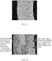
- mechanical or electro-polish smoothing of external surfaces may reduce roughness, as shown in FIG. 3 , but they may not enable surface connected defects to be eliminated in HIP processing.
- encapsulation is required to bridge the surface defects to enable successful HIP processing.
- U.S. Patents 2,654,701 and 3,993,238 disclose zincate plating for aluminum, but they do not disclose diffusing the zinc into the substrate followed by subsequent stripping to enhance surface finish and enable successful encapsulation.
- a method for improving the surface of an aluminum alloy article includes manufacturing the aluminum alloy article using an additive manufacturing technique, wherein the article as-manufactured includes one or more of cracks, roughness, or porosity at a surface of the article; coating the surface of the aluminum alloy article with a diffusion element, the diffusion element being capable of diffusing at least 0.2 mils into the article; heating the aluminum alloy article coated with the diffusion element to cause the diffusion element to diffuse the at least 0.2 mils into the article, thereby forming a diffusion layer of at least 0.2 mils in thickness comprising both aluminum alloy and diffusion element; and removing the diffusion layer from the aluminum alloy article, whereby upon the removing, a resulting improved surface of the article comprises fewer or smaller cracks, reduced roughness, or reduced porosity.
- aluminum alloy refers to any alloy wherein aluminum is the single greatest constituent thereof, as measured on a weight percentage basis.
- aluminum consists of a majority of the alloy, as measured on a weight percentage basis.
- cast alloys like 201 from the difficult to cast 200 series, or 355, 356, or 357 from the 300 series may be employed.
- Wrought alloys like 6061 from the weldable 6000 series or 7075 from the high-strength 7000 series may be utilized.
- non-conventional aluminum alloys include those known as "rapidly solidified powder aluminum alloys", such as 7090 and 7091.
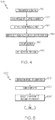
- FIG. 4 is a flow diagram illustrating steps in a method 100 for surface improvement of additively manufactured articles produced with aluminum alloys in accordance with an exemplary embodiment of the present disclosure.
- the method 100 includes a first step 110 of forming, using an additive manufacturing process, an article of manufacture having at least one surface.
- the article of manufacture has both interior and exterior surfaces.
- Additive manufacturing processes can be used to produce complex geometries in a single operation with no tooling. Additive manufacturing technology allows for the article to be produced at a net-shape or near-net shape without the application of the heating, casting, or forging processes commonly used in the prior art.
- the term additive manufacturing refers to any process wherein thin successive layers of material are laid down atop one another to form an article.
- FIG. 5 is a flowchart illustrating a method 200 for manufacturing the article using additive manufacturing techniques.
- a model such as a design model
- the model may be defined in any suitable manner.
- the model may be designed with computer aided design (CAD) software and may include three-dimensional ("3D") numeric coordinates of the entire configuration of the component including both external and internal surfaces.
- the model may include a number of successive two-dimensional ("2D") cross-sectional slices that together form the 3D component.
- step 220 of the method 200 the article is formed according to the model of step 210.
- the entire component is formed using a rapid prototyping or additive layer manufacturing process.
- additive layer manufacturing processes include: selective laser sintering in which a laser is used to sinter a powder media in precisely controlled locations; laser wire deposition in which a wire feedstock is melted by a laser and then deposited and solidified in precise locations to build the product; electron beam melting; laser engineered net shaping; and direct metal deposition.
- additive manufacturing techniques provide flexibility in free-form fabrication without geometric constraints, fast material processing time, and innovative joining techniques.
- direct metal laser fusion DMLF is used to produce the article in step 220.
- DMLF is a commercially-available, laser-based rapid prototyping and tooling process by which complex parts may be directly produced by precision melting and solidification of metal powder into successive layers of larger structures, each layer corresponding to a cross-sectional layer of the 3D component.
- step 220 is performed with DMLF techniques to form the article.
- FIG. 6 is a schematic view of a DMLF system 300 for manufacturing the article in accordance with an exemplary embodiment.
- the system 300 includes a fabrication device 310, a powder delivery device 330, a scanner 340, and a laser 360 that function to manufacture the article 350 (e.g., the article) with build material 370.
- the fabrication device 310 includes a build container 312 with a fabrication support 314 on which the article 350 is formed and supported.
- the fabrication support 314 is movable within the build container 312 in a vertical direction and is adjusted in such a way to define a working plane 316.
- the delivery device 330 includes a powder chamber 332 with a delivery support 334 that supports the build material 370 and is also movable in the vertical direction.
- the delivery device 330 further includes a roller or wiper 336 that transfers build material 370 from the delivery device 330 to the fabrication device 310.
- a base block 340 may be installed on the fabrication support 314.
- the fabrication support 314 is lowered and the delivery support 334 is raised.
- the roller or wiper 336 scrapes or otherwise pushes a portion of the build material 370 from the delivery device 330 to form the working plane 316 in the fabrication device 310.
- the laser 360 emits a laser beam 362, which is directed by the scanner 340 onto the build material 370 in the working plane 316 to selectively fuse the build material 370 into a cross-sectional layer of the article 350 according to the design.
- the speed, position, and other operating parameters of the laser beam 362 are controlled to selectively fuse the powder of the build material 370 into larger structures by rapidly melting the powder particles that may melt or diffuse into the solid structure below, and subsequently, cool and re-solidify.
- each layer of build material 370 may include unfused and fused build material 370 that respectively corresponds to the cross-sectional passages and walls that form the article 350.
- the laser beam 362 is relatively low power to selectively fuse the individual layer of build material 370.
- the laser beam 362 may have a power of approximately 50 to 500 Watts, although any suitable power may be provided.
- the fabrication support 314 Upon completion of a respective layer, the fabrication support 314 is lowered and the delivery support 334 is raised. Typically, the fabrication support 314, and thus the article 350, does not move in a horizontal plane during this step.
- the roller or wiper 336 again pushes a portion of the build material 370 from the delivery device 330 to form an additional layer of build material 370 on the working plane 316 of the fabrication device 310.
- the laser beam 362 is movably supported relative to the article 350 and is again controlled to selectively form another cross-sectional layer.
- the article 350 is positioned in a bed of build material 370 as the successive layers are formed such that the unfused and fused material supports subsequent layers. This process is continued according to the modeled design as successive cross-sectional layers are formed into the completed desired portion, e.g., the component of step 220.
- the delivery of build material 370 and movement of the article 350 in the vertical direction are relatively constant and only the movement of the laser beam 362 is selectively controlled to provide a simpler and more precise implementation.
- the localized fusing of the build material 370 enables more precise placement of fused material to reduce or eliminate the occurrence of over-deposition of material and excessive energy or heat, which may otherwise result in cracking or distortion.
- the unused and unfused build material 370 may be reused, thereby further reducing scrap.
- the build material 370 is provided as an aluminum alloy in powder form. As we noted initially above, non-limiting examples of such aluminum alloys include 201, 355, 356, 357, 6061, and 7075. In general, the powder build material 370 may be selected based on one or more of strength, durability, and useful life, particularly at high temperatures, although it should be appreciated that the powder build material 370 may also be selected based on the intended function of the article being formed.
- the powdered form of the alloy is produced by combining the various constituents (metals and other elements) of the alloy into a mixture, melting the mixture, and atomizing the melted mixture to form a powder, a process which is well-known in the art.
- the article may be given a stress relief treatment, and then is removed from the additive manufacturing system (e.g., from the DMLF system 300).
- the component formed in step 220 may undergo finishing treatments. Finishing treatments may include, for example, polishing, peening, and/or the application of coatings. If necessary, the component may be machined to final specifications.
- the article, produced using additive manufacturing techniques has a layer-by-layer fused microstructure that exhibits anisotropic mechanical and physical properties. It should be noted that these "finishing treatments" of optional step 230, if present, are performed separately from and in addition to the plating, diffusing, stripping, and HIP procedures as are described in greater detail below in connection with the surface improvement processes of the present disclosure.
- method 100 continues with the diffusion of an element (or elements) into the surface of the AM aluminum article, followed by selectively removing the diffusion layer without detrimental attack of the aluminum substrate.
- the rough surface of article 350 is rendered smoother as has been demonstrated in FIG. 7 , which is prophetic. This described operation can be performed repeatedly at appropriate steps in the overall manufacturing sequence, and the diffusion cycle can be sequenced with the component heat treatment cycle.
- FIG. 4 illustrates a step 120, performed after step 110, where a diffusion element is coated onto the aluminum alloy article of manufacture, namely onto its surfaces, including both internal and external surfaces if present.
- a diffusion element is coated onto the aluminum alloy article of manufacture, namely onto its surfaces, including both internal and external surfaces if present.
- One particular embodiment uses zinc as the diffusion element and plating as the coating process, and starts with a conventional zincate plating process for aluminum alloys, widely used as starting point or bond coat for various other plating processes.
- the zincate plating process refers to the alkaline solutions used in a dipping (immersion) process to plate aluminum with zinc. This immersion process is electroless (i.e., not electroplating) and involves the displacement of zinc from zincate by aluminum: ⁇ 3 Zn(OH) 4 2- + 2 Al ⁇ 3 Zn + 2 Al(OH) 4 - + 4 OH-
- tin, silver, gold, copper, nickel or other elements may be electroless coated or electro-plated onto the aluminum alloy instead of zinc; a combination of several different elements or platings may be advantageous depending on the specific application and embodiment.
- the coating material is ideally metallic and capable of subsequent diffusion into the article 350 to form a diffusion coating.
- plating or electroless plating should not be considered the only suitable coating technique. Rather, other coating processes such as spray-based processes, deposition-based processes, non-aqueous plating, molten salt baths, pack plating, and others may be used as well.
- the diffusion element may be applied to an internal surface of the article 350 to ensure that the coating material layer spans the surface-connected porosity and any cracks within.
- Some coatings may be more advantageous for their ability to encapsulate by forming a more continuous layer better suited for subsequent HIP (to improve the internal structure), and not necessarily form a diffusion layer.
- a particular purpose of diffusion coating is to enable subsequent removal to enhance the surface smoothness and metallurgy. While possible that one coating will do both, that is not necessary with proper sequencing. In some situations, it may be advantageous to perform diffusion coating and removal to improve exterior surfaces followed by encapsulation and HIP to improve both interior and exterior surfaces. Instead of removing an encapsulating coating of gold, nickel, etc., leaving such coatings in place may be beneficial to corrosion resistance, etc.
- method 100 continues with a step 130 of heat treating the article 350 and the coating material layer to diffuse the diffusion element and to form the diffusion coating on the article 350.
- the diffusion coating comprises a surface additive layer and a diffusion zone or layer below the surface additive layer.
- the surface additive layer is the coating material layer depleted in one or more elements after diffusing into the parent metal of the material substrate.
- Diffusion heat treating may be performed at elevated temperatures of between about 350° C to about 475° C (662-887° F) for about two hours to about twenty hours. Slow ramping through the melting point of the coating element or eutectics formed during diffusion may be desirable to overcome objectionable melting of this "sacrificial in-process layer".
- the diffusion heat treatment may occur at a temperature and/or for a time period (duration) outside of the aforementioned ranges. After diffusion heat treating, the article 350 may be cooled.
- a primary diffusion zone occurs to some degree between the coating material layer and the substrate as a result of the concentration gradients of the constituents.
- further inter-diffusion occurs as a result of solid-state diffusion across a coating bond line.
- the coating bond line is the demarcation between the applied coating material layer and the substrate.
- the coating bond line is the "edge" of the article 350.
- a thickness of the diffusion layer of about 0.2 to about 3 mils is optimal, and corresponds to how much of the upper portion of the substrate of the first intermediate article will be removed in subsequently described steps. Diffusion time and temperature may be controlled to achieve the desired thickness. If significant surface roughness and surface-connected defects exist, a thicker diffusion coating may be necessary. Internal passage surface diffusion layers may be thinner than diffusion layers on external surfaces and steps can be taken to selectively reduce the thickness of the diffusion layer on the external surfaces to arrive at a more even diffusion coating overall to better hold dimensions following removal of the diffusion coating, as hereinafter described.
- the diffusion element for example, zincate solution
- vacuum impregnation may be employed.
- method 100 continues with a step 140 of removing the diffusion coating (also referred to herein as "stripping") to improve the surface of the article 350.
- the layers of the diffusion coating are substantially removed in their entirety to the coating diffusion boundary thereby forming the improved surface.
- the diffusion layer includes the upper portion of the substrate, the upper portion of the substrate will also be removed.
- the diffusion coating and removal steps function to reduce surface roughness, resulting in the article 350 having enhanced surfaces.
- the coating diffusion boundary should be sufficiently defined or sharp such that removal of the diffusion coating yields a substrate surface composition close to that of the original substrate.
- the diffusion coating may be removed by any known diffusion coating removal technique, including mechanical, chemical, electro-chemical, or any suitable combination thereof.
- the cooled component may be flushed inside and out in a chemical solvent such as ferric chloride, nitric acid, etc.
- the chemical solvent is selected for its ability to remove the diffusion coating, without affecting the integrity of the aluminum alloy article 350.
- the coating removal chemical compositions and concentrations may be modified to optimize the amount of diffusion coating removed and/or the removal time while maintaining the integrity of the substrate.
- the dimensions of the original model for the component may be modified to accommodate removal of the upper portion of the original substrate above the coating diffusion boundary to allow the finished component to meet finished component dimensions.
- the stripping process can be dependent on the particular aluminum alloy, and electrochemical stripping may be used.
- the diffusion layer is removed by forming an anodic aluminum oxide (anodize) coating on the diffusion layer and then removing the combined diffusion/anodize coating chemically.
- forming of the diffusion coating applying and diffusion heat treating steps
- removal thereof hereinafter collectively a "forming and removing cycle”
- forming and removing cycle may optionally be repeated as many times as necessary until the at least one surface of the article is sufficiently enhanced, the sufficiency thereof known to one skilled in the art.
- the term "enhanced” or the like refers to a reduction in surface roughness and/or improvement in metallurgical quality. The improvement in metallurgical quality results from removing surfaces lacking sufficient metallurgical surface integrity caused by inadequately metallurgically diffusion bonded faying surfaces of the surface-connected cracks.
- An encapsulation layer functions to effectively convert the surface porosity and cracks into internal porosity and cracks. Any suitable encapsulation process may be performed that bridges and covers the porosity and cracks in at least one surface of the article.
- the encapsulation layer may have a thickness of approximately 10-100 ⁇ m, although any suitable thickness may be provided. Such encapsulation layer may be subsequently removed or maintained to function as an oxidation protection layer.
- the encapsulation layer may be a metal or alloy that is compatible with the substrate material and may be formed, for example, by a plating process or a coating process.
- the encapsulation layer may be formed for example, by electroless plating or electroplating processes. In further embodiments, the encapsulation layer may be formed by processes including cobalt plating, sol-gel chemical deposition techniques, or low pressure plasma sprays.
- a suitable material for the encapsulation layer is one which when applied or when heated to the HIP temperature is relatively ductile and free of gaps or cracks and which spans the surface-connected porosity and cracks within, for example, internal passages of the aluminum alloy article 350.
- the method 100 may continue with a HIP processing step 160.
- HIP hot isostatic pressing
- the article 350 is subjected to elevated temperatures and pressures over time.
- HIP processing reduces or substantially eliminates internal void defects, such as porosity or cracks.
- the HIP process may be performed at any temperature, pressure, and time that are suitable for diffusion bonding and forming a compacted solid having minor or acceptable levels of porosity, but substantially free of cracks.
- the HIP process may be performed at a processing temperature in a range of about 480° C to about 530° C and may be performed at a pressure in a range of about 1 ksi to about 25 ksi for a time period of about 1 to about 10 hours.
- the HIP processing temperature, pressure, and time may be higher or lower to form a compacted article having negligible cracks and porosity.
- the consolidated article 350 may comprise the finished component.
- the disclosed are methods for surface improvement of additively manufactured articles produced with aluminum alloys.
- the methods diffuse an element into the surface of the aluminum alloy article, and then strip the diffusion layer to create an enhanced surface.
Abstract
Description
- The present disclosure generally relates to additive manufacturing technologies. More particularly, the present disclosure relates to surface improvement of additively manufactured articles produced with aluminum alloys.
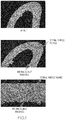
- Additive manufacturing (AM) processes, such as Direct Laser Metal Fusion (DMLF), have recently come to prominence as a cost-effective alternative to traditional manufacturing techniques. However, external and internal (e.g., hollow or cored) surfaces of articles formed by AM can exhibit surface roughness associated with the application of successive layers or the unintended clinging of powder particles to the free edges, as shown in
FIG 1 . Internal defects and surface connected defects, like those shown inFIG. 2 , may render a component unusable. - Prevention of this roughness condition may not be critical if the surface can be subsequently improved in a cost-effective manner. To the extent that such mechanical surface roughness is non-conforming with the engineering design intent or for cosmetic reasons, a means of smoothing the surface (or controlled excess stock removal) is desired, especially those surfaces which are inaccessible to hand-finishing or machine-finishing methods. Additionally, justification for required surface improvement, encapsulation, and subsequent hot isostatic press (HIP) processing extends to various metallurgical reasons including 1) smoothing undesirable surface roughness, 2) smoothing roughness to enable subsequent encapsulation of surface connected porosity and defects for HIP processing to eliminate internal and surface defects in the AM component, 3) removal of metallurgical surface defects such as micro cracking, and 4) being able to predicatively remove excess stock or non-conforming layers without creating metallurgical issues.
-
U.S. Patent 8,506,836 discloses surface finish and encapsulation technologies for nickel-based alloys, but to date no such technology has ever been developed for aluminum alloys. For aluminum alloys, mechanical or electro-polish smoothing of external surfaces may reduce roughness, as shown inFIG. 3 , but they may not enable surface connected defects to be eliminated in HIP processing. Thus, encapsulation is required to bridge the surface defects to enable successful HIP processing.U.S. Patents 2,654,701 and3,993,238 disclose zincate plating for aluminum, but they do not disclose diffusing the zinc into the substrate followed by subsequent stripping to enhance surface finish and enable successful encapsulation. - Accordingly, there remains a need in the art for surface improvement of additively manufactured articles produced with aluminum alloys. Furthermore, other desirable features and characteristics of the disclosure will become apparent from the subsequent detailed description and the appended claims, taken in conjunction with the accompanying drawings and this background of the disclosure.
- The present disclosure relates to surface improvement of additively manufactured articles produced with aluminum alloys. In one exemplary embodiment, a method for improving the surface of an aluminum alloy article includes manufacturing the aluminum alloy article using an additive manufacturing technique, wherein the article as-manufactured includes one or more of cracks, roughness, or porosity at a surface of the article; coating the surface of the aluminum alloy article with a diffusion element, the diffusion element being capable of diffusing at least 0.2 mils into the article; heating the aluminum alloy article coated with the diffusion element to cause the diffusion element to diffuse the at least 0.2 mils into the article, thereby forming a diffusion layer of at least 0.2 mils in thickness comprising both aluminum alloy and diffusion element; and removing the diffusion layer from the aluminum alloy article, whereby upon the removing, a resulting improved surface of the article comprises fewer or smaller cracks, reduced roughness, or reduced porosity.
- This summary is provided to describe select concepts in a simplified form that are further described in the Detailed Description. This summary is not intended to identify key or essential features of the claimed subject matter, nor is it intended to be used as an aid in determining the scope of the claimed subject matter.
- The present disclosure will hereinafter be described in conjunction with the following drawing figures, wherein like numerals denote like elements, and wherein:
-
FIG. 1 is an image of an article of manufacture made with additive manufacturing techniques, which exhibits surface roughness that would render it unsuitable for subsequent HIP processing; -
FIG. 2 is an image of an article of manufacture made with additive manufacturing techniques, which exhibits surface connected defects and internal defects that can be improved via encapsulation and HIP processing; -
FIG. 3 is an image of an article of manufacture made with additive manufacturing techniques, which exhibits an external surface that has been smoothed via electro-chemical means, yet which still exhibits an internal surface having roughness that would render it unsuitable for subsequent HIP processing; -
FIG. 4 is a flow diagram illustrating steps in a method for surface improvement of additively manufactured articles produced with aluminum alloys in accordance with an exemplary embodiment of the present disclosure; -
FIG. 5 is a flowchart illustrating a method for manufacturing the article using additive manufacturing techniques in accordance with an exemplary embodiment; -
FIG. 6 , which is a schematic view of an AM system for manufacturing the article in accordance with an exemplary embodiment; and -
FIG. 7 illustrates an article of manufacture having its surfaces smoothed using techniques in accordance with embodiments of the present disclosure. - The following detailed description is merely exemplary in nature and is not intended to limit the invention or the application and uses of the invention. As used herein, the word "exemplary" means "serving as an example, instance, or illustration." Thus, any embodiment described herein as "exemplary" is not necessarily to be construed as preferred or advantageous over other embodiments. All of the embodiments described herein are exemplary embodiments provided to enable persons skilled in the art to make or use the invention and not to limit the scope of the invention which is defined by the claims. Furthermore, there is no intention to be bound by any expressed or implied theory presented in the preceding technical field, background, brief summary, or the following detailed description.
- As used herein, the term "aluminum alloy" refers to any alloy wherein aluminum is the single greatest constituent thereof, as measured on a weight percentage basis. One example of this is the class of alloys where aluminum consists of a majority of the alloy, as measured on a weight percentage basis. To give some non-limiting examples of aluminum alloys, the following cast and wrought alloys may be utilized. Cast alloys like 201 from the difficult to cast 200 series, or 355, 356, or 357 from the 300 series may be employed. Wrought alloys like 6061 from the weldable 6000 series or 7075 from the high-strength 7000 series may be utilized. Other alloys may also be employed as are well-known to those having ordinary skill in the art, such as the utilization of aluminum alloy 8009 in additive manufacturing applications. Conventional cast or wrought aluminum alloys may be modified and optimized for additive manufacturing. The rapid solidification rates at which these alloys are deposited, layer by layer, allow for the creation of unique microstructures using various additive elements that could not be realized using ordinary cast/wrought alloy techniques. For purposes of this disclosure, this newer class of aluminum alloys will be referred to as "non-conventional" aluminum alloys. An exemplary, a class of non-conventional alloys includes those known as "rapidly solidified powder aluminum alloys", such as 7090 and 7091.
-
FIG. 4 is a flow diagram illustrating steps in amethod 100 for surface improvement of additively manufactured articles produced with aluminum alloys in accordance with an exemplary embodiment of the present disclosure. Themethod 100 includes afirst step 110 of forming, using an additive manufacturing process, an article of manufacture having at least one surface. In some examples, the article of manufacture has both interior and exterior surfaces. Additive manufacturing processes can be used to produce complex geometries in a single operation with no tooling. Additive manufacturing technology allows for the article to be produced at a net-shape or near-net shape without the application of the heating, casting, or forging processes commonly used in the prior art. Thus, as used herein, the term additive manufacturing refers to any process wherein thin successive layers of material are laid down atop one another to form an article. -
FIG. 5 is a flowchart illustrating amethod 200 for manufacturing the article using additive manufacturing techniques. In afirst step 210, a model, such as a design model, of the article may be defined in any suitable manner. For example, the model may be designed with computer aided design (CAD) software and may include three-dimensional ("3D") numeric coordinates of the entire configuration of the component including both external and internal surfaces. In one exemplary embodiment, the model may include a number of successive two-dimensional ("2D") cross-sectional slices that together form the 3D component. - In
step 220 of themethod 200, the article is formed according to the model ofstep 210. In one exemplary embodiment, the entire component is formed using a rapid prototyping or additive layer manufacturing process. Some examples of additive layer manufacturing processes include: selective laser sintering in which a laser is used to sinter a powder media in precisely controlled locations; laser wire deposition in which a wire feedstock is melted by a laser and then deposited and solidified in precise locations to build the product; electron beam melting; laser engineered net shaping; and direct metal deposition. In general, additive manufacturing techniques provide flexibility in free-form fabrication without geometric constraints, fast material processing time, and innovative joining techniques. In one particular exemplary embodiment, direct metal laser fusion (DMLF) is used to produce the article instep 220. DMLF is a commercially-available, laser-based rapid prototyping and tooling process by which complex parts may be directly produced by precision melting and solidification of metal powder into successive layers of larger structures, each layer corresponding to a cross-sectional layer of the 3D component. - As such, in one exemplary embodiment,
step 220 is performed with DMLF techniques to form the article. However, prior to a discussion of the subsequent method steps, reference is made toFIG. 6 , which is a schematic view of aDMLF system 300 for manufacturing the article in accordance with an exemplary embodiment. - Referring to
FIG. 6 , thesystem 300 includes afabrication device 310, apowder delivery device 330, ascanner 340, and alaser 360 that function to manufacture the article 350 (e.g., the article) withbuild material 370. Thefabrication device 310 includes abuild container 312 with afabrication support 314 on which thearticle 350 is formed and supported. Thefabrication support 314 is movable within thebuild container 312 in a vertical direction and is adjusted in such a way to define a workingplane 316. Thedelivery device 330 includes apowder chamber 332 with adelivery support 334 that supports thebuild material 370 and is also movable in the vertical direction. Thedelivery device 330 further includes a roller orwiper 336 that transfersbuild material 370 from thedelivery device 330 to thefabrication device 310. - During operation, a
base block 340 may be installed on thefabrication support 314. Thefabrication support 314 is lowered and thedelivery support 334 is raised. The roller orwiper 336 scrapes or otherwise pushes a portion of thebuild material 370 from thedelivery device 330 to form the workingplane 316 in thefabrication device 310. Thelaser 360 emits alaser beam 362, which is directed by thescanner 340 onto thebuild material 370 in the workingplane 316 to selectively fuse thebuild material 370 into a cross-sectional layer of thearticle 350 according to the design. More specifically, the speed, position, and other operating parameters of thelaser beam 362 are controlled to selectively fuse the powder of thebuild material 370 into larger structures by rapidly melting the powder particles that may melt or diffuse into the solid structure below, and subsequently, cool and re-solidify. As such, based on the control of thelaser beam 362, each layer ofbuild material 370 may include unfused and fusedbuild material 370 that respectively corresponds to the cross-sectional passages and walls that form thearticle 350. In general, thelaser beam 362 is relatively low power to selectively fuse the individual layer ofbuild material 370. As an example, thelaser beam 362 may have a power of approximately 50 to 500 Watts, although any suitable power may be provided. - Upon completion of a respective layer, the
fabrication support 314 is lowered and thedelivery support 334 is raised. Typically, thefabrication support 314, and thus thearticle 350, does not move in a horizontal plane during this step. The roller orwiper 336 again pushes a portion of thebuild material 370 from thedelivery device 330 to form an additional layer ofbuild material 370 on the workingplane 316 of thefabrication device 310. Thelaser beam 362 is movably supported relative to thearticle 350 and is again controlled to selectively form another cross-sectional layer. As such, thearticle 350 is positioned in a bed ofbuild material 370 as the successive layers are formed such that the unfused and fused material supports subsequent layers. This process is continued according to the modeled design as successive cross-sectional layers are formed into the completed desired portion, e.g., the component ofstep 220. - The delivery of
build material 370 and movement of thearticle 350 in the vertical direction are relatively constant and only the movement of thelaser beam 362 is selectively controlled to provide a simpler and more precise implementation. The localized fusing of thebuild material 370 enables more precise placement of fused material to reduce or eliminate the occurrence of over-deposition of material and excessive energy or heat, which may otherwise result in cracking or distortion. The unused andunfused build material 370 may be reused, thereby further reducing scrap. - Any suitable laser and laser parameters may be used, including considerations with respect to power, laser beam spot size, and scanning velocity. The
build material 370 is provided as an aluminum alloy in powder form. As we noted initially above, non-limiting examples of such aluminum alloys include 201, 355, 356, 357, 6061, and 7075. In general, thepowder build material 370 may be selected based on one or more of strength, durability, and useful life, particularly at high temperatures, although it should be appreciated that thepowder build material 370 may also be selected based on the intended function of the article being formed. The powdered form of the alloy is produced by combining the various constituents (metals and other elements) of the alloy into a mixture, melting the mixture, and atomizing the melted mixture to form a powder, a process which is well-known in the art. - Returning to
FIG. 5 , at the completion ofstep 220, the article may be given a stress relief treatment, and then is removed from the additive manufacturing system (e.g., from the DMLF system 300). Inoptional step 230, the component formed instep 220 may undergo finishing treatments. Finishing treatments may include, for example, polishing, peening, and/or the application of coatings. If necessary, the component may be machined to final specifications. The article, produced using additive manufacturing techniques, has a layer-by-layer fused microstructure that exhibits anisotropic mechanical and physical properties. It should be noted that these "finishing treatments" ofoptional step 230, if present, are performed separately from and in addition to the plating, diffusing, stripping, and HIP procedures as are described in greater detail below in connection with the surface improvement processes of the present disclosure. - Returning to
FIG. 4 , after thearticle 350 has been formed with the aluminum alloy using the additive manufacturing process as described above with regard to step 110 ofmethod 100, it should be expected that thearticle 350 will exhibit surface roughness, as illustrated in detail inFIGS. 1-3 . This roughness would prevent the use and/or successful application of beneficial HIP processing techniques to improve thearticle 350. Thus, in accordance with embodiments of thepresent disclosure method 100 continues with the diffusion of an element (or elements) into the surface of the AM aluminum article, followed by selectively removing the diffusion layer without detrimental attack of the aluminum substrate. In the course of doing so, the rough surface ofarticle 350 is rendered smoother as has been demonstrated inFIG. 7 , which is prophetic. This described operation can be performed repeatedly at appropriate steps in the overall manufacturing sequence, and the diffusion cycle can be sequenced with the component heat treatment cycle. - Thus,
FIG. 4 illustrates astep 120, performed afterstep 110, where a diffusion element is coated onto the aluminum alloy article of manufacture, namely onto its surfaces, including both internal and external surfaces if present. One particular embodiment uses zinc as the diffusion element and plating as the coating process, and starts with a conventional zincate plating process for aluminum alloys, widely used as starting point or bond coat for various other plating processes. In the prior art, such coatings are done after all heat treating is completed. For example, the zincate plating process refers to the alkaline solutions used in a dipping (immersion) process to plate aluminum with zinc. This immersion process is electroless (i.e., not electroplating) and involves the displacement of zinc from zincate by aluminum:
→ 3 Zn(OH)4 2- + 2 Al → 3 Zn + 2 Al(OH)4- + 4 OH-
- Alternatively, tin, silver, gold, copper, nickel or other elements may be electroless coated or electro-plated onto the aluminum alloy instead of zinc; a combination of several different elements or platings may be advantageous depending on the specific application and embodiment. The coating material is ideally metallic and capable of subsequent diffusion into the
article 350 to form a diffusion coating. Moreover, plating or electroless plating should not be considered the only suitable coating technique. Rather, other coating processes such as spray-based processes, deposition-based processes, non-aqueous plating, molten salt baths, pack plating, and others may be used as well. The diffusion element may be applied to an internal surface of thearticle 350 to ensure that the coating material layer spans the surface-connected porosity and any cracks within. Some coatings may be more advantageous for their ability to encapsulate by forming a more continuous layer better suited for subsequent HIP (to improve the internal structure), and not necessarily form a diffusion layer. A particular purpose of diffusion coating is to enable subsequent removal to enhance the surface smoothness and metallurgy. While possible that one coating will do both, that is not necessary with proper sequencing. In some situations, it may be advantageous to perform diffusion coating and removal to improve exterior surfaces followed by encapsulation and HIP to improve both interior and exterior surfaces. Instead of removing an encapsulating coating of gold, nickel, etc., leaving such coatings in place may be beneficial to corrosion resistance, etc. - Once the
article 350 has been coated with the diffusion element,method 100 continues with astep 130 of heat treating thearticle 350 and the coating material layer to diffuse the diffusion element and to form the diffusion coating on thearticle 350. The diffusion coating comprises a surface additive layer and a diffusion zone or layer below the surface additive layer. The surface additive layer is the coating material layer depleted in one or more elements after diffusing into the parent metal of the material substrate. - Diffusion heat treating may be performed at elevated temperatures of between about 350° C to about 475° C (662-887° F) for about two hours to about twenty hours. Slow ramping through the melting point of the coating element or eutectics formed during diffusion may be desirable to overcome objectionable melting of this "sacrificial in-process layer". In other embodiments, the diffusion heat treatment may occur at a temperature and/or for a time period (duration) outside of the aforementioned ranges. After diffusion heat treating, the
article 350 may be cooled. - During the
coating step 120, if performed at a sufficiently elevated temperature, a primary diffusion zone occurs to some degree between the coating material layer and the substrate as a result of the concentration gradients of the constituents. At elevated temperatures of the diffusionheat treating step 130, further inter-diffusion occurs as a result of solid-state diffusion across a coating bond line. The coating bond line is the demarcation between the applied coating material layer and the substrate. The coating bond line is the "edge" of thearticle 350. - A thickness of the diffusion layer of about 0.2 to about 3 mils is optimal, and corresponds to how much of the upper portion of the substrate of the first intermediate article will be removed in subsequently described steps. Diffusion time and temperature may be controlled to achieve the desired thickness. If significant surface roughness and surface-connected defects exist, a thicker diffusion coating may be necessary. Internal passage surface diffusion layers may be thinner than diffusion layers on external surfaces and steps can be taken to selectively reduce the thickness of the diffusion layer on the external surfaces to arrive at a more even diffusion coating overall to better hold dimensions following removal of the diffusion coating, as hereinafter described. To reach internal or hollow portions of the article, the diffusion element (for example, zincate solution) may be flowed through the article. To reach "dead-end" passages, vacuum impregnation may be employed.
- Still referring to
FIG. 4 , according to exemplary embodiments,method 100 continues with astep 140 of removing the diffusion coating (also referred to herein as "stripping") to improve the surface of thearticle 350. The layers of the diffusion coating are substantially removed in their entirety to the coating diffusion boundary thereby forming the improved surface. As the diffusion layer includes the upper portion of the substrate, the upper portion of the substrate will also be removed. The diffusion coating and removal steps function to reduce surface roughness, resulting in thearticle 350 having enhanced surfaces. The coating diffusion boundary should be sufficiently defined or sharp such that removal of the diffusion coating yields a substrate surface composition close to that of the original substrate. - The diffusion coating may be removed by any known diffusion coating removal technique, including mechanical, chemical, electro-chemical, or any suitable combination thereof. For example, the cooled component may be flushed inside and out in a chemical solvent such as ferric chloride, nitric acid, etc. The chemical solvent is selected for its ability to remove the diffusion coating, without affecting the integrity of the
aluminum alloy article 350. The coating removal chemical compositions and concentrations may be modified to optimize the amount of diffusion coating removed and/or the removal time while maintaining the integrity of the substrate. The dimensions of the original model for the component may be modified to accommodate removal of the upper portion of the original substrate above the coating diffusion boundary to allow the finished component to meet finished component dimensions. The stripping process can be dependent on the particular aluminum alloy, and electrochemical stripping may be used. In another embodiment for stripping, the diffusion layer is removed by forming an anodic aluminum oxide (anodize) coating on the diffusion layer and then removing the combined diffusion/anodize coating chemically. - If, after performing steps 120-140, there is residual surface roughness or surfaces with inadequate diffusion bonded faying surfaces ("diffusion bonding failures"), forming of the diffusion coating (applying and diffusion heat treating steps) and removal thereof (hereinafter collectively a "forming and removing cycle") may optionally be repeated as many times as necessary until the at least one surface of the article is sufficiently enhanced, the sufficiency thereof known to one skilled in the art. As noted above, the term "enhanced" or the like refers to a reduction in surface roughness and/or improvement in metallurgical quality. The improvement in metallurgical quality results from removing surfaces lacking sufficient metallurgical surface integrity caused by inadequately metallurgically diffusion bonded faying surfaces of the surface-connected cracks.
- After the one or more forming and removing cycles are performed, the
method 100 may continue with anencapsulation step 150. An encapsulation layer functions to effectively convert the surface porosity and cracks into internal porosity and cracks. Any suitable encapsulation process may be performed that bridges and covers the porosity and cracks in at least one surface of the article. For example, the encapsulation layer may have a thickness of approximately 10-100 µm, although any suitable thickness may be provided. Such encapsulation layer may be subsequently removed or maintained to function as an oxidation protection layer. The encapsulation layer may be a metal or alloy that is compatible with the substrate material and may be formed, for example, by a plating process or a coating process. In various exemplary embodiments, the encapsulation layer may be formed for example, by electroless plating or electroplating processes. In further embodiments, the encapsulation layer may be formed by processes including cobalt plating, sol-gel chemical deposition techniques, or low pressure plasma sprays. A suitable material for the encapsulation layer is one which when applied or when heated to the HIP temperature is relatively ductile and free of gaps or cracks and which spans the surface-connected porosity and cracks within, for example, internal passages of thealuminum alloy article 350. - After encapsulation, the
method 100 may continue with aHIP processing step 160. In the hot isostatic pressing (HIP) process, thearticle 350 is subjected to elevated temperatures and pressures over time. HIP processing reduces or substantially eliminates internal void defects, such as porosity or cracks. The HIP process may be performed at any temperature, pressure, and time that are suitable for diffusion bonding and forming a compacted solid having minor or acceptable levels of porosity, but substantially free of cracks. For example, the HIP process may be performed at a processing temperature in a range of about 480° C to about 530° C and may be performed at a pressure in a range of about 1 ksi to about 25 ksi for a time period of about 1 to about 10 hours. In other embodiments, the HIP processing temperature, pressure, and time may be higher or lower to form a compacted article having negligible cracks and porosity. Theconsolidated article 350 may comprise the finished component. - Accordingly, the disclosed are methods for surface improvement of additively manufactured articles produced with aluminum alloys. The methods diffuse an element into the surface of the aluminum alloy article, and then strip the diffusion layer to create an enhanced surface.
- In this document, relational terms such as first and second, and the like may be used solely to distinguish one entity or action from another entity or action without necessarily requiring or implying any actual such relationship or order between such entities or actions. Numerical ordinals such as "first," "second," "third," etc. simply denote different singles of a plurality and do not imply any order or sequence unless specifically defined by the claim language. The sequence of the text in any of the claims does not imply that process steps must be performed in a temporal or logical order according to such sequence unless it is specifically defined by the language of the claim. The process steps may be interchanged in any order without departing from the scope of the invention as long as such an interchange does not contradict the claim language and is not logically nonsensical.
- Furthermore, depending on the context, words such as "connect" or "coupled to" used in describing a relationship between different elements do not imply that a direct physical connection must be made between these elements. For example, two elements may be connected to each other physically, electronically, logically, or in any other manner, through one or more additional elements.
- While at least one exemplary embodiment has been presented in the foregoing detailed description of the invention, it should be appreciated that a vast number of variations exist. It should also be appreciated that the exemplary embodiment or exemplary embodiments are only examples, and are not intended to limit the scope, applicability, or configuration of the invention in any way. Rather, the foregoing detailed description will provide those skilled in the art with a convenient road map for implementing an exemplary embodiment of the invention. It being understood that various changes may be made in the function and arrangement of elements described in an exemplary embodiment without departing from the scope of the invention as set forth in the appended claims.
Claims (14)
- A method for improving the surface of an aluminum alloy article comprising:manufacturing the aluminum alloy article using an additive manufacturing technique, wherein the article as-manufactured comprises one or more of cracks, roughness, or porosity at a surface of the article;coating the surface of the aluminum alloy article with an encapsulating element, which may or may not also be a diffusion element, to facilitate HIP response;coating the surface of the aluminum alloy article with a diffusion element, the diffusion element being capable of diffusing at least 0.2 mils into the article;heating the aluminum alloy article coated with the diffusion element to cause the diffusion element to diffuse the at least 0.2 mils into the article, thereby forming a diffusion layer of at least 0.2 mils in thickness comprising both aluminum alloy and diffusion element;removing the diffusion layer from the aluminum alloy article, whereby upon the removing, a resulting improved surface of the article comprises fewer or smaller cracks, reduced roughness, or reduced porosity.
- The method of claim 1, wherein the aluminum alloy article comprises an aluminum alloy selected from the group consisting of: cast alloys, wrought alloys, derivatives of said cast or wrought alloys having slightly modified composition for improved additive manufacturing, and non-conventional alloys, such as those known as rapidly solidified aluminum powders.
- The method of claim 1, wherein the additive manufacturing technique is selected from the group consisting of: direct metal laser sintering, direct metal laser fusion, electron beam melting, and selective laser sintering.
- The method of claim 1, wherein the diffusion element comprises zinc.
- The method of claim 1, wherein the diffusion element comprises tin.
- The method of claim 1, wherein the diffusion and/or encapsulating element is selected from the group consisting of: electroless silver, gold, copper, and nickel.
- The method of claim 1, wherein coating the surface comprises an electroless plating process or wherein coating the surface comprises an electrolytic plating process where feasible.
- The method of claim 7, wherein coating the surface comprises a zincate plating process.
- The method of claim 1, wherein the diffusion element diffuses at least 1 mil into the article.
- The method of claim 1, further comprising repeating the steps of coating, heating, and removing an additional one or more times.
- The method of claim 11, wherein coating with the encapsulating occurs after the removing step.
- The method of claim 1, further comprising hot isostatic pressing the article.
- The method of claim 1, wherein hot isostatic pressing occurs after the removing step.
- The method of claim 1, wherein the aluminum alloy article is a component of a gas turbine engine.
Applications Claiming Priority (1)
| Application Number | Priority Date | Filing Date | Title |
|---|---|---|---|
| US14/933,154 US10105798B2 (en) | 2015-11-05 | 2015-11-05 | Surface improvement of additively manufactured articles produced with aluminum alloys |
Publications (2)
| Publication Number | Publication Date |
|---|---|
| EP3165305A1 true EP3165305A1 (en) | 2017-05-10 |
| EP3165305B1 EP3165305B1 (en) | 2019-04-24 |
Family
ID=57256063
Family Applications (1)
| Application Number | Title | Priority Date | Filing Date |
|---|---|---|---|
| EP16195390.6A Active EP3165305B1 (en) | 2015-11-05 | 2016-10-24 | Surface improvement of additively manufactured articles produced with aluminum alloys |
Country Status (2)
| Country | Link |
|---|---|
| US (3) | US10105798B2 (en) |
| EP (1) | EP3165305B1 (en) |
Cited By (6)
| Publication number | Priority date | Publication date | Assignee | Title |
|---|---|---|---|---|
| EP3228406A1 (en) * | 2016-04-04 | 2017-10-11 | Rolls-Royce plc | Method of manufacture of a component |
| GB2556429A (en) * | 2016-09-28 | 2018-05-30 | Hamilton Sundstrand Corp | Adjusting porosity in powder metal articles |
| EP3418423A1 (en) * | 2017-06-23 | 2018-12-26 | Hamilton Sundstrand Corporation | Method for smoothing surface roughness of components |
| EP3459657A1 (en) * | 2017-09-25 | 2019-03-27 | Hamilton Sundstrand Corporation | Additive manufacturing limited |
| WO2019192633A1 (en) * | 2018-04-06 | 2019-10-10 | Hermle Maschinenbau Gmbh | Method for producing a component, capsule for hot isostatic pressing and component arrangement |
| EP3670694A1 (en) * | 2018-12-20 | 2020-06-24 | Delavan, Inc. | Additively manufactured article and method of coating same |
Families Citing this family (11)
| Publication number | Priority date | Publication date | Assignee | Title |
|---|---|---|---|---|
| EP3397400B1 (en) * | 2015-12-28 | 2023-06-14 | Matheson Tri-Gas, Inc. | Use of reactive fluids in additive manufacturing and the products made therefrom |
| EP3459653A1 (en) * | 2017-09-20 | 2019-03-27 | Siemens Aktiengesellschaft | Method for manufacturing a component and component |
| US20190134899A1 (en) * | 2017-11-06 | 2019-05-09 | 3D Systems, Inc. | Three dimensional printer with pressure compensation for induced stresses |
| CN110193602B (en) * | 2018-02-27 | 2022-04-22 | 西门子公司 | Method for improving inner surface quality of 3D printing piece |
| FR3083479B1 (en) * | 2018-07-09 | 2021-08-13 | C Tec Constellium Tech Center | METHOD OF MANUFACTURING AN ALUMINUM ALLOY PART |
| US11426818B2 (en) | 2018-08-10 | 2022-08-30 | The Research Foundation for the State University | Additive manufacturing processes and additively manufactured products |
| US10759116B2 (en) | 2018-09-14 | 2020-09-01 | Intrepid Automation | Additive manufactured parts with smooth surface finishes |
| WO2020122992A1 (en) * | 2018-12-12 | 2020-06-18 | Arconic Inc. | Methods for producing metallic parts |
| US11242769B2 (en) | 2018-12-17 | 2022-02-08 | Raytheon Technologies Corporation | Additively controlled surface roughness for designed performance |
| US20220048109A1 (en) * | 2020-08-17 | 2022-02-17 | Honeywell International Inc. | Lightweight stiffened panels made using additive manufacturing techniques |
| CZ2021388A3 (en) * | 2021-08-19 | 2023-03-01 | Výzkumný A Zkušební Ústav Plzeň S.R.O. | A method of manufacturing a component with a surface coating |
Citations (4)
| Publication number | Priority date | Publication date | Assignee | Title |
|---|---|---|---|---|
| US2654701A (en) | 1950-06-08 | 1953-10-06 | Edwin R Calderon | Plating aluminum |
| US3993238A (en) | 1974-01-04 | 1976-11-23 | Fulmer Research Institute Limited | Bonding of aluminium alloys |
| US20130071562A1 (en) * | 2011-09-16 | 2013-03-21 | Honeywell International Inc. | Methods for manufacturing components from articles formed by additive-manufacturing processes |
| US20140199175A1 (en) * | 2013-01-14 | 2014-07-17 | Honeywell International Inc. | Gas turbine engine components and methods for their manufacture using additive manufacturing techniques |
Family Cites Families (5)
| Publication number | Priority date | Publication date | Assignee | Title |
|---|---|---|---|---|
| US9175568B2 (en) * | 2010-06-22 | 2015-11-03 | Honeywell International Inc. | Methods for manufacturing turbine components |
| US9085980B2 (en) | 2011-03-04 | 2015-07-21 | Honeywell International Inc. | Methods for repairing turbine components |
| ES2586820T3 (en) * | 2011-09-13 | 2016-10-19 | Monnaie Royale Canadienne/Royal Canadian Mint | Aluminum galvanized |
| US9289826B2 (en) | 2012-09-17 | 2016-03-22 | Honeywell International Inc. | Turbine stator airfoil assemblies and methods for their manufacture |
| US20140169971A1 (en) * | 2012-12-18 | 2014-06-19 | Hamilton Sundstrand Corporation | Additively manufactured impeller |
-
2015
- 2015-11-05 US US14/933,154 patent/US10105798B2/en active Active
-
2016
- 2016-10-24 EP EP16195390.6A patent/EP3165305B1/en active Active
-
2018
- 2018-08-09 US US16/059,620 patent/US10940566B2/en active Active
- 2018-08-09 US US16/059,595 patent/US10933497B2/en active Active
Patent Citations (5)
| Publication number | Priority date | Publication date | Assignee | Title |
|---|---|---|---|---|
| US2654701A (en) | 1950-06-08 | 1953-10-06 | Edwin R Calderon | Plating aluminum |
| US3993238A (en) | 1974-01-04 | 1976-11-23 | Fulmer Research Institute Limited | Bonding of aluminium alloys |
| US20130071562A1 (en) * | 2011-09-16 | 2013-03-21 | Honeywell International Inc. | Methods for manufacturing components from articles formed by additive-manufacturing processes |
| US8506836B2 (en) | 2011-09-16 | 2013-08-13 | Honeywell International Inc. | Methods for manufacturing components from articles formed by additive-manufacturing processes |
| US20140199175A1 (en) * | 2013-01-14 | 2014-07-17 | Honeywell International Inc. | Gas turbine engine components and methods for their manufacture using additive manufacturing techniques |
Cited By (8)
| Publication number | Priority date | Publication date | Assignee | Title |
|---|---|---|---|---|
| EP3228406A1 (en) * | 2016-04-04 | 2017-10-11 | Rolls-Royce plc | Method of manufacture of a component |
| GB2556429A (en) * | 2016-09-28 | 2018-05-30 | Hamilton Sundstrand Corp | Adjusting porosity in powder metal articles |
| GB2556429B (en) * | 2016-09-28 | 2020-08-19 | Hamilton Sundstrand Corp | Adjusting porosity in powder metal articles |
| EP3418423A1 (en) * | 2017-06-23 | 2018-12-26 | Hamilton Sundstrand Corporation | Method for smoothing surface roughness of components |
| EP3459657A1 (en) * | 2017-09-25 | 2019-03-27 | Hamilton Sundstrand Corporation | Additive manufacturing limited |
| US11123819B2 (en) | 2017-09-25 | 2021-09-21 | Hamilton Sundstrand Corporation | Additive manufacturing method |
| WO2019192633A1 (en) * | 2018-04-06 | 2019-10-10 | Hermle Maschinenbau Gmbh | Method for producing a component, capsule for hot isostatic pressing and component arrangement |
| EP3670694A1 (en) * | 2018-12-20 | 2020-06-24 | Delavan, Inc. | Additively manufactured article and method of coating same |
Also Published As
| Publication number | Publication date |
|---|---|
| US20170129060A1 (en) | 2017-05-11 |
| US10933497B2 (en) | 2021-03-02 |
| US20180345424A1 (en) | 2018-12-06 |
| US10105798B2 (en) | 2018-10-23 |
| EP3165305B1 (en) | 2019-04-24 |
| US10940566B2 (en) | 2021-03-09 |
| US20180345423A1 (en) | 2018-12-06 |
Similar Documents
| Publication | Publication Date | Title |
|---|---|---|
| US10933497B2 (en) | Surface improvement of additively manufactured articles produced with aluminum alloys | |
| EP3034639B1 (en) | Nickel-based superalloys and additive manufacturing processes using nickel-based superalloys | |
| EP3072611A2 (en) | Net-shape or near-net shape powder metal components and methods for producing the same | |
| EP2754515B1 (en) | Methods for the manufacture of gas turbine engine components using additive manufacturing techniques | |
| AU2013223879B2 (en) | Processing of metal or alloy objects | |
| US9039917B2 (en) | Methods for manufacturing components from articles formed by additive-manufacturing processes | |
| CN106413946B (en) | Method for manufacturing a metal or metal matrix composite part by an operation of additive manufacturing followed by forging of the part | |
| US20150144496A1 (en) | Methods and systems for manufacturing components from articles formed by additive-manufacturing processes | |
| US20120217226A1 (en) | Method and device for producing a component of a turbomachine | |
| US11193216B2 (en) | Methods and systems for electrochemical machining of articles formed by additive manufacturing | |
| EP3427869A1 (en) | Additive manufacturing methods and related components | |
| JP2004050225A (en) | Method for producing metal-made formed material | |
| US20240058862A1 (en) | Build materials having a powder mixture comprising graphene, methods of producing articles therefrom, and articles produced therewith | |
| Mocanu et al. | Defects in additive manufacturing and their influence on structural integrity | |
| US20220097139A1 (en) | Method for the production of parts made from metal or metal matrix composite and resulting from additive manufacturing followed by an operation involving the forging of said parts | |
| CA3048456A1 (en) | Manufactured metal objects with hollow channels and method for fabrication thereof |
Legal Events
| Date | Code | Title | Description |
|---|---|---|---|
| PUAI | Public reference made under article 153(3) epc to a published international application that has entered the european phase |
Free format text: ORIGINAL CODE: 0009012 |
|
| STAA | Information on the status of an ep patent application or granted ep patent |
Free format text: STATUS: REQUEST FOR EXAMINATION WAS MADE |
|
| 17P | Request for examination filed |
Effective date: 20161024 |
|
| AK | Designated contracting states |
Kind code of ref document: A1 Designated state(s): AL AT BE BG CH CY CZ DE DK EE ES FI FR GB GR HR HU IE IS IT LI LT LU LV MC MK MT NL NO PL PT RO RS SE SI SK SM TR |
|
| AX | Request for extension of the european patent |
Extension state: BA ME |
|
| GRAP | Despatch of communication of intention to grant a patent |
Free format text: ORIGINAL CODE: EPIDOSNIGR1 |
|
| STAA | Information on the status of an ep patent application or granted ep patent |
Free format text: STATUS: GRANT OF PATENT IS INTENDED |
|
| RIC1 | Information provided on ipc code assigned before grant |
Ipc: B22F 3/26 20060101ALI20181108BHEP Ipc: B22F 5/00 20060101ALI20181108BHEP Ipc: B22F 3/15 20060101ALI20181108BHEP Ipc: C23C 10/60 20060101ALI20181108BHEP Ipc: F01D 5/28 20060101ALI20181108BHEP Ipc: B22F 3/24 20060101ALI20181108BHEP Ipc: B33Y 10/00 20150101ALI20181108BHEP Ipc: C22C 1/04 20060101ALI20181108BHEP Ipc: B22F 3/105 20060101AFI20181108BHEP Ipc: C22C 21/00 20060101ALI20181108BHEP Ipc: C23C 10/28 20060101ALI20181108BHEP |
|
| INTG | Intention to grant announced |
Effective date: 20181207 |
|
| GRAS | Grant fee paid |
Free format text: ORIGINAL CODE: EPIDOSNIGR3 |
|
| GRAA | (expected) grant |
Free format text: ORIGINAL CODE: 0009210 |
|
| STAA | Information on the status of an ep patent application or granted ep patent |
Free format text: STATUS: THE PATENT HAS BEEN GRANTED |
|
| AK | Designated contracting states |
Kind code of ref document: B1 Designated state(s): AL AT BE BG CH CY CZ DE DK EE ES FI FR GB GR HR HU IE IS IT LI LT LU LV MC MK MT NL NO PL PT RO RS SE SI SK SM TR |
|
| REG | Reference to a national code |
Ref country code: GB Ref legal event code: FG4D |
|
| REG | Reference to a national code |
Ref country code: CH Ref legal event code: EP |
|
| REG | Reference to a national code |
Ref country code: AT Ref legal event code: REF Ref document number: 1123540 Country of ref document: AT Kind code of ref document: T Effective date: 20190515 Ref country code: IE Ref legal event code: FG4D |
|
| REG | Reference to a national code |
Ref country code: DE Ref legal event code: R096 Ref document number: 602016012784 Country of ref document: DE |
|
| REG | Reference to a national code |
Ref country code: NL Ref legal event code: MP Effective date: 20190424 |
|
| REG | Reference to a national code |
Ref country code: LT Ref legal event code: MG4D |
|
| PG25 | Lapsed in a contracting state [announced via postgrant information from national office to epo] |
Ref country code: NL Free format text: LAPSE BECAUSE OF FAILURE TO SUBMIT A TRANSLATION OF THE DESCRIPTION OR TO PAY THE FEE WITHIN THE PRESCRIBED TIME-LIMIT Effective date: 20190424 |
|
| PG25 | Lapsed in a contracting state [announced via postgrant information from national office to epo] |
Ref country code: HR Free format text: LAPSE BECAUSE OF FAILURE TO SUBMIT A TRANSLATION OF THE DESCRIPTION OR TO PAY THE FEE WITHIN THE PRESCRIBED TIME-LIMIT Effective date: 20190424 Ref country code: LT Free format text: LAPSE BECAUSE OF FAILURE TO SUBMIT A TRANSLATION OF THE DESCRIPTION OR TO PAY THE FEE WITHIN THE PRESCRIBED TIME-LIMIT Effective date: 20190424 Ref country code: PT Free format text: LAPSE BECAUSE OF FAILURE TO SUBMIT A TRANSLATION OF THE DESCRIPTION OR TO PAY THE FEE WITHIN THE PRESCRIBED TIME-LIMIT Effective date: 20190824 Ref country code: FI Free format text: LAPSE BECAUSE OF FAILURE TO SUBMIT A TRANSLATION OF THE DESCRIPTION OR TO PAY THE FEE WITHIN THE PRESCRIBED TIME-LIMIT Effective date: 20190424 Ref country code: AL Free format text: LAPSE BECAUSE OF FAILURE TO SUBMIT A TRANSLATION OF THE DESCRIPTION OR TO PAY THE FEE WITHIN THE PRESCRIBED TIME-LIMIT Effective date: 20190424 Ref country code: SE Free format text: LAPSE BECAUSE OF FAILURE TO SUBMIT A TRANSLATION OF THE DESCRIPTION OR TO PAY THE FEE WITHIN THE PRESCRIBED TIME-LIMIT Effective date: 20190424 Ref country code: NO Free format text: LAPSE BECAUSE OF FAILURE TO SUBMIT A TRANSLATION OF THE DESCRIPTION OR TO PAY THE FEE WITHIN THE PRESCRIBED TIME-LIMIT Effective date: 20190724 Ref country code: ES Free format text: LAPSE BECAUSE OF FAILURE TO SUBMIT A TRANSLATION OF THE DESCRIPTION OR TO PAY THE FEE WITHIN THE PRESCRIBED TIME-LIMIT Effective date: 20190424 |
|
| PG25 | Lapsed in a contracting state [announced via postgrant information from national office to epo] |
Ref country code: GR Free format text: LAPSE BECAUSE OF FAILURE TO SUBMIT A TRANSLATION OF THE DESCRIPTION OR TO PAY THE FEE WITHIN THE PRESCRIBED TIME-LIMIT Effective date: 20190725 Ref country code: RS Free format text: LAPSE BECAUSE OF FAILURE TO SUBMIT A TRANSLATION OF THE DESCRIPTION OR TO PAY THE FEE WITHIN THE PRESCRIBED TIME-LIMIT Effective date: 20190424 Ref country code: BG Free format text: LAPSE BECAUSE OF FAILURE TO SUBMIT A TRANSLATION OF THE DESCRIPTION OR TO PAY THE FEE WITHIN THE PRESCRIBED TIME-LIMIT Effective date: 20190724 Ref country code: LV Free format text: LAPSE BECAUSE OF FAILURE TO SUBMIT A TRANSLATION OF THE DESCRIPTION OR TO PAY THE FEE WITHIN THE PRESCRIBED TIME-LIMIT Effective date: 20190424 Ref country code: PL Free format text: LAPSE BECAUSE OF FAILURE TO SUBMIT A TRANSLATION OF THE DESCRIPTION OR TO PAY THE FEE WITHIN THE PRESCRIBED TIME-LIMIT Effective date: 20190424 |
|
| REG | Reference to a national code |
Ref country code: AT Ref legal event code: MK05 Ref document number: 1123540 Country of ref document: AT Kind code of ref document: T Effective date: 20190424 |
|
| PG25 | Lapsed in a contracting state [announced via postgrant information from national office to epo] |
Ref country code: IS Free format text: LAPSE BECAUSE OF FAILURE TO SUBMIT A TRANSLATION OF THE DESCRIPTION OR TO PAY THE FEE WITHIN THE PRESCRIBED TIME-LIMIT Effective date: 20190824 |
|
| REG | Reference to a national code |
Ref country code: DE Ref legal event code: R097 Ref document number: 602016012784 Country of ref document: DE |
|
| PG25 | Lapsed in a contracting state [announced via postgrant information from national office to epo] |
Ref country code: AT Free format text: LAPSE BECAUSE OF FAILURE TO SUBMIT A TRANSLATION OF THE DESCRIPTION OR TO PAY THE FEE WITHIN THE PRESCRIBED TIME-LIMIT Effective date: 20190424 Ref country code: EE Free format text: LAPSE BECAUSE OF FAILURE TO SUBMIT A TRANSLATION OF THE DESCRIPTION OR TO PAY THE FEE WITHIN THE PRESCRIBED TIME-LIMIT Effective date: 20190424 Ref country code: DK Free format text: LAPSE BECAUSE OF FAILURE TO SUBMIT A TRANSLATION OF THE DESCRIPTION OR TO PAY THE FEE WITHIN THE PRESCRIBED TIME-LIMIT Effective date: 20190424 Ref country code: SK Free format text: LAPSE BECAUSE OF FAILURE TO SUBMIT A TRANSLATION OF THE DESCRIPTION OR TO PAY THE FEE WITHIN THE PRESCRIBED TIME-LIMIT Effective date: 20190424 Ref country code: RO Free format text: LAPSE BECAUSE OF FAILURE TO SUBMIT A TRANSLATION OF THE DESCRIPTION OR TO PAY THE FEE WITHIN THE PRESCRIBED TIME-LIMIT Effective date: 20190424 Ref country code: CZ Free format text: LAPSE BECAUSE OF FAILURE TO SUBMIT A TRANSLATION OF THE DESCRIPTION OR TO PAY THE FEE WITHIN THE PRESCRIBED TIME-LIMIT Effective date: 20190424 |
|
| PG25 | Lapsed in a contracting state [announced via postgrant information from national office to epo] |
Ref country code: SM Free format text: LAPSE BECAUSE OF FAILURE TO SUBMIT A TRANSLATION OF THE DESCRIPTION OR TO PAY THE FEE WITHIN THE PRESCRIBED TIME-LIMIT Effective date: 20190424 Ref country code: IT Free format text: LAPSE BECAUSE OF FAILURE TO SUBMIT A TRANSLATION OF THE DESCRIPTION OR TO PAY THE FEE WITHIN THE PRESCRIBED TIME-LIMIT Effective date: 20190424 |
|
| PLBE | No opposition filed within time limit |
Free format text: ORIGINAL CODE: 0009261 |
|
| STAA | Information on the status of an ep patent application or granted ep patent |
Free format text: STATUS: NO OPPOSITION FILED WITHIN TIME LIMIT |
|
| PG25 | Lapsed in a contracting state [announced via postgrant information from national office to epo] |
Ref country code: TR Free format text: LAPSE BECAUSE OF FAILURE TO SUBMIT A TRANSLATION OF THE DESCRIPTION OR TO PAY THE FEE WITHIN THE PRESCRIBED TIME-LIMIT Effective date: 20190424 |
|
| 26N | No opposition filed |
Effective date: 20200127 |
|
| PG25 | Lapsed in a contracting state [announced via postgrant information from national office to epo] |
Ref country code: SI Free format text: LAPSE BECAUSE OF FAILURE TO SUBMIT A TRANSLATION OF THE DESCRIPTION OR TO PAY THE FEE WITHIN THE PRESCRIBED TIME-LIMIT Effective date: 20190424 Ref country code: MC Free format text: LAPSE BECAUSE OF FAILURE TO SUBMIT A TRANSLATION OF THE DESCRIPTION OR TO PAY THE FEE WITHIN THE PRESCRIBED TIME-LIMIT Effective date: 20190424 |
|
| REG | Reference to a national code |
Ref country code: CH Ref legal event code: PL |
|
| PG25 | Lapsed in a contracting state [announced via postgrant information from national office to epo] |
Ref country code: LI Free format text: LAPSE BECAUSE OF NON-PAYMENT OF DUE FEES Effective date: 20191031 Ref country code: CH Free format text: LAPSE BECAUSE OF NON-PAYMENT OF DUE FEES Effective date: 20191031 Ref country code: LU Free format text: LAPSE BECAUSE OF NON-PAYMENT OF DUE FEES Effective date: 20191024 |
|
| REG | Reference to a national code |
Ref country code: BE Ref legal event code: MM Effective date: 20191031 |
|
| PG25 | Lapsed in a contracting state [announced via postgrant information from national office to epo] |
Ref country code: BE Free format text: LAPSE BECAUSE OF NON-PAYMENT OF DUE FEES Effective date: 20191031 |
|
| PG25 | Lapsed in a contracting state [announced via postgrant information from national office to epo] |
Ref country code: FR Free format text: LAPSE BECAUSE OF NON-PAYMENT OF DUE FEES Effective date: 20191031 Ref country code: IE Free format text: LAPSE BECAUSE OF NON-PAYMENT OF DUE FEES Effective date: 20191024 |
|
| PG25 | Lapsed in a contracting state [announced via postgrant information from national office to epo] |
Ref country code: CY Free format text: LAPSE BECAUSE OF FAILURE TO SUBMIT A TRANSLATION OF THE DESCRIPTION OR TO PAY THE FEE WITHIN THE PRESCRIBED TIME-LIMIT Effective date: 20190424 |
|
| GBPC | Gb: european patent ceased through non-payment of renewal fee |
Effective date: 20201024 |
|
| PG25 | Lapsed in a contracting state [announced via postgrant information from national office to epo] |
Ref country code: HU Free format text: LAPSE BECAUSE OF FAILURE TO SUBMIT A TRANSLATION OF THE DESCRIPTION OR TO PAY THE FEE WITHIN THE PRESCRIBED TIME-LIMIT; INVALID AB INITIO Effective date: 20161024 Ref country code: MT Free format text: LAPSE BECAUSE OF FAILURE TO SUBMIT A TRANSLATION OF THE DESCRIPTION OR TO PAY THE FEE WITHIN THE PRESCRIBED TIME-LIMIT Effective date: 20190424 |
|
| PG25 | Lapsed in a contracting state [announced via postgrant information from national office to epo] |
Ref country code: GB Free format text: LAPSE BECAUSE OF NON-PAYMENT OF DUE FEES Effective date: 20201024 |
|
| PG25 | Lapsed in a contracting state [announced via postgrant information from national office to epo] |
Ref country code: MK Free format text: LAPSE BECAUSE OF FAILURE TO SUBMIT A TRANSLATION OF THE DESCRIPTION OR TO PAY THE FEE WITHIN THE PRESCRIBED TIME-LIMIT Effective date: 20190424 |
|
| P01 | Opt-out of the competence of the unified patent court (upc) registered |
Effective date: 20230525 |
|
| PGFP | Annual fee paid to national office [announced via postgrant information from national office to epo] |
Ref country code: DE Payment date: 20231027 Year of fee payment: 8 |