EP3151389A2 - Rotary electric machine - Google Patents
Rotary electric machine Download PDFInfo
- Publication number
- EP3151389A2 EP3151389A2 EP16191445.2A EP16191445A EP3151389A2 EP 3151389 A2 EP3151389 A2 EP 3151389A2 EP 16191445 A EP16191445 A EP 16191445A EP 3151389 A2 EP3151389 A2 EP 3151389A2
- Authority
- EP
- European Patent Office
- Prior art keywords
- bus bar
- phase
- windings
- crossover wire
- protrusion
- Prior art date
- Legal status (The legal status is an assumption and is not a legal conclusion. Google has not performed a legal analysis and makes no representation as to the accuracy of the status listed.)
- Granted
Links
- 238000004804 winding Methods 0.000 claims abstract description 240
- 230000007935 neutral effect Effects 0.000 claims description 75
- 239000012212 insulator Substances 0.000 claims description 45
- 230000007423 decrease Effects 0.000 description 29
- 238000009413 insulation Methods 0.000 description 26
- 238000010276 construction Methods 0.000 description 19
- 238000003466 welding Methods 0.000 description 12
- 238000004519 manufacturing process Methods 0.000 description 10
- 239000011347 resin Substances 0.000 description 5
- 229920005989 resin Polymers 0.000 description 5
- 238000009751 slip forming Methods 0.000 description 3
- 238000010586 diagram Methods 0.000 description 2
- 238000000034 method Methods 0.000 description 2
- 238000005304 joining Methods 0.000 description 1
- 230000002093 peripheral effect Effects 0.000 description 1
- 239000011800 void material Substances 0.000 description 1
Images


Classifications
-
- H—ELECTRICITY
- H02—GENERATION; CONVERSION OR DISTRIBUTION OF ELECTRIC POWER
- H02K—DYNAMO-ELECTRIC MACHINES
- H02K3/00—Details of windings
- H02K3/46—Fastening of windings on the stator or rotor structure
- H02K3/52—Fastening salient pole windings or connections thereto
- H02K3/521—Fastening salient pole windings or connections thereto applicable to stators only
- H02K3/522—Fastening salient pole windings or connections thereto applicable to stators only for generally annular cores with salient poles
-
- H—ELECTRICITY
- H02—GENERATION; CONVERSION OR DISTRIBUTION OF ELECTRIC POWER
- H02K—DYNAMO-ELECTRIC MACHINES
- H02K3/00—Details of windings
- H02K3/04—Windings characterised by the conductor shape, form or construction, e.g. with bar conductors
- H02K3/28—Layout of windings or of connections between windings
-
- H—ELECTRICITY
- H02—GENERATION; CONVERSION OR DISTRIBUTION OF ELECTRIC POWER
- H02K—DYNAMO-ELECTRIC MACHINES
- H02K1/00—Details of the magnetic circuit
- H02K1/06—Details of the magnetic circuit characterised by the shape, form or construction
- H02K1/12—Stationary parts of the magnetic circuit
- H02K1/14—Stator cores with salient poles
- H02K1/146—Stator cores with salient poles consisting of a generally annular yoke with salient poles
-
- H—ELECTRICITY
- H02—GENERATION; CONVERSION OR DISTRIBUTION OF ELECTRIC POWER
- H02K—DYNAMO-ELECTRIC MACHINES
- H02K1/00—Details of the magnetic circuit
- H02K1/06—Details of the magnetic circuit characterised by the shape, form or construction
- H02K1/22—Rotating parts of the magnetic circuit
- H02K1/27—Rotor cores with permanent magnets
- H02K1/2706—Inner rotors
-
- H—ELECTRICITY
- H02—GENERATION; CONVERSION OR DISTRIBUTION OF ELECTRIC POWER
- H02K—DYNAMO-ELECTRIC MACHINES
- H02K3/00—Details of windings
- H02K3/04—Windings characterised by the conductor shape, form or construction, e.g. with bar conductors
- H02K3/18—Windings for salient poles
-
- H—ELECTRICITY
- H02—GENERATION; CONVERSION OR DISTRIBUTION OF ELECTRIC POWER
- H02K—DYNAMO-ELECTRIC MACHINES
- H02K2203/00—Specific aspects not provided for in the other groups of this subclass relating to the windings
- H02K2203/06—Machines characterised by the wiring leads, i.e. conducting wires for connecting the winding terminations
-
- H—ELECTRICITY
- H02—GENERATION; CONVERSION OR DISTRIBUTION OF ELECTRIC POWER
- H02K—DYNAMO-ELECTRIC MACHINES
- H02K2203/00—Specific aspects not provided for in the other groups of this subclass relating to the windings
- H02K2203/09—Machines characterised by wiring elements other than wires, e.g. bus rings, for connecting the winding terminations
Definitions
- This disclosure generally relates to a rotary electric machine.
- a known rotary electric machine including plural bus bars is disclosed, for example, in JP2015-97450A which is hereinafter referred to as Reference 1.
- a known rotary electric machine including concentrated winding coils is disclosed, for example, in JP2013-223322A which is hereinafter referred to as Reference 2.
- the rotary electric machine disclosed in Reference 1 includes a stator where plural stator pieces are annularly disposed in a circumferential direction relative to an axis of the stator and a rotor disposed coaxially with the stator and facing the stator.
- the stator pieces are constituted by plural split cores including projecting teeth at which phase coils (windings) are wound respectively, the phase coils corresponding to W-phase coils, V-phase coils and U-phase coils.
- the stator includes the plural bus bars, specifically, a W-phase bus bar, a V-phase bus bar, a U-phase bus bar and a common bus bar, which supply an electric power to the corresponding phase coils and which are connected to the corresponding stator pieces for the respective phases so as to maintain an annular arrangement of the split cores.
- Each of the W-phase bus bar, the V-phase bus bar, the U-phase bus bar and the common bus bar is formed in an annular plate.
- the W-phase bus bar, the V-phase bus bar and the U-phase bus bar are disposed at positions corresponding to the W-phase coils, the V-phase coils and the U-phase coils, respectively.
- the rotary electric machine disclosed in Reference 2 includes a stator core including twelve teeth.
- the concentrated winding coils are constituted as three-phase alternating current windings in a state where the four concentrated winding coils are connected in parallel to one another for each phase.
- the concentrated winding coil wound at each of the teeth includes a coil terminal at each of a winding start portion and a winding end portion. That is, the two coil terminals are provided at each of the teeth.
- the twenty-four coil terminals in total are provided at the rotary electric machine.
- the rotary electric machine includes three bus bars each of which includes four coil connection terminals and one bus bar for a neutral point connection including twelve coil connection terminals. In the rotary electric machine disclosed in Reference 2, the coil terminals of the concentrated winding coils and the coil connection terminals of the bus bars are connected by welding to thereby achieve a Y-connection of the concentrated winding coils.
- the bus bar in a case where each of the bus bars is assembled on the stator, the bus bar may be assembled in a wrong phase (wrong rotation direction position), which may lead to a connection failure between the bus bar and the phase coils.
- the coil terminals terminal members
- the two terminal members are necessary for each of the concentrated winding coils wound at the teeth.
- the number of welding for connecting the concentrated winding coils and the terminal members is required for the number of the terminal members. As a result, the number of welding (number of manufacturing processes) may be relatively large.
- a rotary electric machine includes a rotor core fixed at a rotation axis, a stator core arranged facing the rotor core and including a plurality of teeth, a plurality of windings wound at the plurality of teeth of the stator core, a plurality of winding connection terminals connected to respective ends of the plurality of windings, a plurality of bus bars connected to the plurality of winding connection terminals, each of the plurality of bus bars being formed in either an arc form or an annular form, and a bus bar holder holding the plurality of bus bars in a laminated state and including a holder engagement portion engaging with a bus bar engagement portion which is provided at least at one of the plurality of bus bars.
- the bus bar engagement portion engages with the holder engagement portion so that each of the bus bars is assembled on the bus bar holder at a predetermined phase (at a predetermined rotation direction position).
- each of the bus bars is restrained from being assembled in a wrong phase.
- possibility of connection failure between the bus bars and the windings may decrease.
- the holder engagement portion includes a plurality of protrusions which include different heights from one another in a rotation axis direction of the rotor core. At least one of the plurality of protrusions is configured to be inhibited from protruding in the rotation axis direction by engaging with the bus bar engagement portion provided at least at one of the plurality of bus bars.
- any one of the bus bars where the bus bar engagement portion is not provided at a portion corresponding to the position of the holder engagement portion which is inhibited from protruding in the axial direction because of the engagement with the bus bar engagement portion of any other of the bus bars may be placed upon any other of the bus bars. That is, any one of the bus bars where the bus bar engagement portion is provided so as to engage with the holder engagement portion serving as a predetermined holder engagement portion which is inhibited from protruding in the axial direction because of the engagement with the aforementioned bus bar engagement portion, and any other of the bus bars where the bus bar engagement portion is not provided for the engagement with the aforementioned predetermined base engagement portion are assembled in the mentioned order.
- the bus bars are restrained from being assembled in a wrong order and possibility of connection failure between the bus bars and the windings may decrease.
- the plurality of protrusions includes a first protrusion, a second protrusion and a third protrusion
- the plurality of bus bars including a first phase bus bar which includes a first recess, a second phase bus bar which includes a second recess and a third phase bus bar which includes a third recess.
- the first protrusion is inhibited from protruding from the first phase bus bar in a state where the first protrusion and the first recess engage with each other
- the second protrusion is inhibited from protruding from the second phase bus bar in a state where the second protrusion and the second recess engage with each other
- the third protrusion is inhibited from protruding from the third phase bus bar in a state where the third protrusion and the third recess engage with each other.
- the numbers of protrusions protruding from the first phase bus bar, the second phase bus bar and the third phase bus bar in a case where the first phase bus bar, the second phase bus bar and the third phase bus bar are assembled respectively are different from one another.
- the first to third phase bus bars are restrained from being assembled in the wrong order and possibility of connection failure between the first to third phase bus bars and the windings may decrease.
- a height of the third protrusion in the rotation axis direction is greater than a height of the second protrusion in the rotation axis direction while the height of the second protrusion in the rotation axis direction is greater than a height of the first protrusion in the rotation axis direction.
- the first phase bus bar, the second phase bus bar and the third phase bus bar are configured to be placed in order from a lower side in the rotation axis direction at an upper portion of the bus bar holder.
- the first phase bus bar, the second phase bus bar and the third phase bus bar may interfere with at least one of the plural protrusions in a case where the first phase bus bar, the second phase bus bar and the third phase bus bar are assembled in the wrong order.
- the first to third phase bus bars are placed in the aforementioned order, the first to third phase bus bars are restrained from being assembled in the wrong order and possibility of connection failure between the first to third phase bus bars and the windings may decrease.
- the first recess includes a plurality of first recesses and the second recess includes a plurality of second recesses.
- Number of the plurality of first recesses is greater than number of the plurality of second recesses, and the number of the plurality of second recesses is greater than number of the third recess.
- the first phase bus bar, the second phase bus bar and the third phase bus bar are sequentially placed in the mentioned order from the lower side in the axial direction, the number of protrusions protruding from the first phase bus bar, the second phase bus bar and the third phase bus bar decreases and the number of recesses decreases. Consequently, the first to third phase bus bars are restrained from being assembled in the wrong phase (wrong rotation direction position). In addition, the first to third phase bus bars are restrained from being assembled in the wrong order.
- the bus bar holder includes a phase bus bar non-engagement protrusion which is inhibited from engaging with any one of the first phase bus bar, the second phase bus bar and the third phase bus bar.
- Each of the first phase bus bar, the second phase bus bar and the third phase bus bar is formed in an arc form.
- a height of the phase bus bar non-engagement protrusion in the rotation axis direction is specified to be greater than a height of a lower end surface of at least one of the first phase bus bar, the second phase bus bar and the third phase bus bar in the axial direction.
- the phase bus bar non-engagement protrusion protrudes from a surface of the aforementioned one of the first to third phase bus bars.
- at least one of the first to third phase bus bars is restrained from being assembled in the wrong phase (wrong rotation direction position).
- the bus bar engagement portion is not provided at a portion corresponding to a portion where the phase bus bar non-engagement protrusion protrudes from the surface of at least one of the first to third phase bus bars
- assembly of the aforementioned one of the first to third phase bus bars where the bus bar engagement portion is not provided may be impossible.
- the first to third phase bus bars are therefore restrained from being assembled in the wrong order.
- a rotary electric machine includes a rotor core, a stator core arranged facing the rotor core and including a plurality of teeth, a plurality of windings in which a three-phase voltage is induced and which is connected in a Y-connection, the plurality of windings being wound in a concentrated manner at the plurality of teeth of the stator core, a crossover wire portion connecting a winding start portion of one of the plurality of windings and a winding end portion of another one of the plurality of windings, and a terminal member connected to the crossover wire portion.
- the winding start portion of one of the windings and the winding end portion of another one of the windings may be connected to the common terminal member so that the single power terminal may be provided for the single winding (tooth). Accordingly, as compared to a case where two terminal members are provided for the single winding, the number of terminal members may decrease by half. In addition, because of decrease of the number of terminal members by half, the number of welding for connecting the windings to the terminal members may decrease by half. As a result, the number of terminal members decreases by half and the number of manufacturing processes may decrease.
- the rotary electric machine further includes an insulator provided to cover the plurality of teeth to insulate between the stator core and the plurality of windings.
- the terminal member includes a power connection terminal.
- the crossover wire portion includes a common phase crossover wire portion which is connected to the power connection terminal to connect between two windings in the plurality of windings, the two windings serving as same phase windings.
- the insulator includes a crossover wire arrangement portion at an outer circumferential side of the stator core when viewed in an axial direction so that the common phase crossover wire portion is arranged at the crossover wire arrangement portion.
- the common phase crossover wire portion is disposed at the crossover wire arrangement portion so as to connect the aforementioned two windings.
- the crossover wire arrangement portion is provided at the insulator, so that an exclusive member for arranging the common phase crossover wire portion is not necessary, which restrains the increase of the number of components.
- the crossover wire arrangement portion includes a flange portion which is provided at an outer circumferential portion of the insulator and which is disposed at a lower side in the axial direction than the terminal member.
- the common phase crossover wire portion includes a first common phase crossover wire portion disposed from the flange portion to the power connection terminal for one phase of the three-phase voltage.
- the insulator includes a first restriction portion arranged at a height position between the flange portion and the power connection terminal to restrict a height position of the first common phase crossover wire portion.
- a height position of the first common phase crossover wire portion may be restricted to a predetermined height position by the first restriction portion.
- the common phase crossover wire portion includes a second common phase crossover wire portion connected to the power connection terminal for the other phase of the three-phase voltage disposed from one of the teeth to the flange portion.
- the insulator includes a second restriction portion restricting a height position of the second common phase crossover wire portion in a state where the first common phase crossover wire portion and the second common phase crossover wire portion are separated from each other in a radial direction of the rotor core.
- first common phase crossover wire portion and the second common phase crossover wire portion in which different phase voltages are induced are arranged separating from each other.
- interference or short-circuit may be restrained from occurring between the first common phase crossover wire portion and the second common phase crossover wire portion.
- the plurality of windings includes four windings serving as same phase windings.
- the crossover wire portion includes two common phase crossover wire portions each of which connects between the two windings in the four windings serving as the same phase windings.
- the power connection terminal includes two power connection terminals provided corresponding to the two common phase crossover wire portions.
- the rotary electric machine further includes a bus bar connected to the two power connection terminals and to an external terminal.
- the number of welding for connecting the power connection terminals to the bus bars may decrease by half as compared to a case where the two terminal members are provided for the single winding. As a result, the number of manufacturing processes may decrease.
- the terminal member includes a neutral point connection terminal.
- the crossover wire portion is configured to connect the winding start portion of one of the plurality of windings and the winding end portion of another one of the plurality of windings, one of the plurality of windings and another one of the plurality of windings serving as different phase windings from each other, the one of the plurality of windings being wound at one of the teeth adjacent to another one of the teeth at which the another one of the plurality of windings is wound, the crossover wire portion being connected to the neutral point connection terminal.
- the winding start portion of one of the windings and the winding end portion of another one of the windings are connected to the common neutral point connection terminal.
- the neutral point connection terminal is provided at either the winding start portion or the winding end portion of each of the windings, the number of neutral point connection terminals may decrease by half.
- the crossover wire portion and the windings are obtained by a continuous wire.
- the crossover wire portion may be continuously formed to the aforementioned winding wound at each of the teeth.
- a first embodiment is explained with reference to the attached drawings.
- a motor 100 according to the first embodiment is explained with reference to Figs. 1 to 10 .
- the motor 100 serving as an example of a rotary electric machine is constituted as a brushless motor.
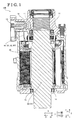
- the motor 100 includes a casing 10, a stator core 20 and a rotor core 30.
- the rotor core 30 is disposed at an inner side (i.e., a radially inner side) of the stator core 20 in an annular form so as to face the stator core 20.
- a circumferential direction corresponds to a circumferential direction of the rotor core 30 or the stator core 20.
- a radial direction corresponds to a radial direction of the rotor core 30.
- an axial direction corresponds to a rotation axis direction of the rotor core 30.
- the casing 10 is provided to cover an outer peripheral surface of the stator core 20.
- the casing 10 includes bearings 11 and 12 so as to support a rotation axis of the rotor core 30 by the bearings 11 and 12.
- Three external connection terminals 13 each of which serves as an external terminal are provided at the casing 10.
- the external connection terminals 13 are supplied or applied with three-phase voltages, specifically, a U-phase voltage, a V-phase voltage and a W-phase voltage, respectively. In Fig. 1 , one of the external connection terminals 13 is only illustrated.
- the three external connection terminals 13 are arranged along a direction in parallel to a Y-axis direction.
- plural (for example, twelve) teeth 22 are provided at the stator core 20 so as to protrude from a back yoke 21 towards a radially inner side.
- slots 23 are provided at the stator core 20 in a manner where each of the slots 23 is disposed between the adjacent teeth 22.
- Windings 50 (see Fig. 3 ) are wound at the teeth 22 (slots 23) in a concentrated manner (i.e., the windings 50 serve as concentrated windings) via an insulator 40 (see Figs. 4 and 5 ).
- the twelve teeth 22 are assigned with different numbers 1 to 12.
- Plural (for example, eight) permanent magnets 31 are embedded in the rotor core 30 at substantially equal angular intervals in the circumferential direction.
- Each of the permanent magnets 31 includes a substantially rectangular cross section when viewed in the axial direction.
- the motor 100 is configured as an 8-pole 12-slot motor accordingly.
- the windings 50 include plural (for example, four) U-phase windings 51 a, 51 b, 51 c and 51 d serving as the same phase windings connected in parallel to one another, plural (for example, four) V-phase windings 52a, 52b, 52c and 52d serving as the same phase windings connected in parallel to one another, and plural (for example, four) W-phase windings 53a, 53b, 53c and 53d serving as the same phase windings connected in parallel to one another.
- First ends of the U-phase windings 51 a, 51 b, 51 c and 51 d, first ends of the V-phase windings 52a, 52b, 52c and 52d, and first ends of the W-phase windings 53a, 53b, 53c and 53d are applied or induced with corresponding voltages, i.e., the U-phase voltage, the V-phase voltage and the W-phase voltage, respectively.
- Second ends of the U-phase windings 51 a, 51 b, 51 c and 51 d, second ends of the V-phase windings 52a, 52b, 52c and 52d, and second ends of the W-phase windings 53a, 53b, 53c and 53d are connected to a neutral point (N).
- the windings 50 are connected in a three-phase and four-parallel Y connection (star connection).
- the U-phase windings 51 a, 51 b, 51 c and 51 d, the V-phase windings 52a, 52b, 52c and 52d, and the W-phase windings 53a, 53b, 53c and 53d are simply described as the windings 50 in a case where the windings 51 a to 51 d, 52a to 52d and 53a to 53d are not specifically distinguished from one another.
- the motor 100 includes power bus bars 81, 82 and 83.
- the power bus bars 81 to 83 are connected to power terminals 101 (i.e., power terminals 101 a, 101 b, 101 c, 101 d, 101 e and 101f).
- the power bus bar 82 is connected to the U-phase power terminals 101 a and 101 b.
- the power bus bar 83 is connected to the V-phase power terminals 101c and 101d.
- the power bus bar 81 is connected to the W-phase power terminals 101 e and 101f.
- the power bus bars 81 to 83 are connected to the respective external connection terminals 13 (see Fig. 1 ).
- the motor 100 includes a neutral point bus bar 84.
- the neutral point bus bar 84 is connected to all neutral point terminals 102 (i.e., neutral point terminals 102a, 102b, 102c, 102d, 102e and 102f). Accordingly, the motor 100 is connected in the three-phase and four-parallel Y connection.
- the power bus bar 82 serves as an example of a first phase bus bar.
- the power bus bar 81 serves as an example of a second phase bus bar.
- the power bus bar 83 serves as an example of a third phase bus bar.
- the neutral point bus bar 84 serves as an example of a common bus bar.
- Each of the power terminal 101 and the neutral point terminal 102 serves as an example of a winding connection terminal.
- the power terminals 101 and the neutral point terminals 102 are connected to respective ends of the windings 50.
- the insulator 40 is provided to cover the plural teeth 22 of the stator core 20.
- the insulator 40 is configured to insulate between the stator core 20 and the plural windings 50.
- the motor 100 includes a base portion 90 which is arranged at an axially upper side of the insulator 40 and which includes an annular configuration, and three insulation members 74 disposed between the power bus bars 81 to 83, respectively, in the axial direction.
- the base portion 90 serves as an example of a bus bar holder.
- the base portion 90 is made of resin, for example, including insulation properties.
- the base portion 90 is arranged at the axially upper side of a position at which the teeth 22 of the stator core 20 are provided and at the upper side of the insulator 40 at which the windings 50 are wound.
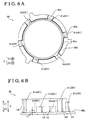
- Each of the power bus bars 81 to 83 is formed in a thin plate and an arc form.
- the neutral point bus bar 84 is formed in a thin plate and an annular form.
- the insulation members 74 are made of resin, for example, and are arranged between the neutral point bus bar 84, the power bus bars 81, 82 and 83, respectively, in the axial direction so as to insulate therebetween.
- the base portion 90, the neutral point bus bar 84, one of the three insulation members 74, the power bus bar 82, another one of the three insulation members 74, the power bus bar 81, still another one of the three insulation members 74 and the power bus bar 83 are assembled in the mentioned order from a lower side in the axial direction (i.e., assembled in an arrow Z1 direction).
- base engagement portions 91 (specifically, base engagement portions 91 a, 91 b, 91 c, 91 d, 91 e and 91 f) each of which is in a protruding form are provided at the base portion 90.
- the power bus bars 81 to 83 include bus bar engagement portions 73b (specifically, bus bar engagement portions 731 b, 732b and 733b) each of which is in a recess form.
- the insulation members 74 include insulation engagement portions 74a each of which is in a recess form.
- the base engagement portions 91 are configured to engage with the bus bar engagement portions 73b of the power bus bars 81 to 83 and the insulation engagement portions 74a of the insulation members 74. As a result, positions of the neutral point bus bar 84 and the power bus bars 81 to 83 in the circumferential direction are restricted.
- the base engagement portion 91 serves as an example of a holder engagement portion.
- the motor 100 (rotary electric machine) includes the power bus bars 81 to 83 each of which is in an arc form and which are connected to the plural power terminals 101, and the neutral point bus bar 84 in an annular form connected to the plural neutral point terminals 102.
- the base portion 90 includes the base engagement portions 91 holding the power bus bars 81 to 83 and the neutral point bus bar 84 as in a laminated manner and engaging with the bus bar engagement portions 73b provided at least at one of the power bus bars 81, 82, 83 and the neutral point bus bar 84.
- the power bus bar 81 includes the two bus bar engagement portions 731 b.
- the power bus bar 82 includes the three bus bar engagement portions 732b.
- the power bus bar 83 includes the single bus bar engagement portion 733b.
- the neutral point bus bar 84 includes the six bus bar engagement portions 73b.
- the base portion 90 includes the six base engagement portions 91 which engage with the bus bar engagement portions 73b provided at least at one of the power bus bars 81 to 83 and the neutral point bus bar 84.
- the six base engagement portions 91 engage with the six bus bar engagement portions 73b of the neutral point bus bar 84.
- the base portion 90 includes six groove portions 90a.
- the base engagement portions 91 (specifically, the base engagement portions 91 a, 91 b, 91 c, 91 d, 91e and 91f) are provided at upper portions of the respective groove portions 90a.
- members other than the base portion 90, the insulation members 74, the power bus bars 81 to 83 and the neutral point bus bar 84 are omitted.
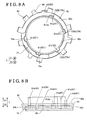
- the plural base engagement portions 91 include different heights from one another in the axial direction. At least one of the plural base engagement portions 91 engages with the bus bar engagement portion 73b of at least one of the plural bus bars 81 to 83 and 84 so as not to protrude in the axial direction.
- the base engagement portion 91f serving as one of the plural base engagement portions 91 protrudes by a height h1 from a surface 90b (i.e., a lower end surface) of the base portion 90.
- Each of the base engagement portions 91 a and 91 d protrudes by a height h2 which is higher than the height h1 (for example, three times higher than the height h1) from the surface 90b.
- the base engagement portion 91 b protrudes by a height h3 which is higher than the height h2 (for example, five times higher than the height h1) from the surface 90b.
- Each of the base engagement portions 91 c and 91 e protrudes by a height h4 which is higher than the height h3 (for example, seventh times higher than the height h1) from the surface 90b so as to be coplanar with an upper end surface 90c (see Fig. 6A ) of the base portion 90.
- the neutral point bus bar 84 includes the six bus bar engagement portions 73b which engage with the six base engagement portions 91 in a case where the neutral point bus bar 84 is placed onto the base portion 90.
- the plural base engagement portions 91 include the base engagement portions 91 a, 91b and 91 c.
- the power bus bars 81 to 83 include the bus bar engagement portions 731 b, 732b and 733b.
- the base engagement portion 91 a engages with the bus bar engagement portion 732b
- the base engagement portion 91 a is inhibited from protruding from the power bus bar 82 as illustrated in Fig. 8B .
- the base engagement portion 91 b engages with the bus bar engagement portion 731 b
- the base engagement portion 91 b is inhibited from protruding from the power bus bar 81 as illustrated in Fig. 9B .
- the base engagement portion 91 c In a state where the base engagement portion 91 c engages with the bus bar engagement portion 733b, the base engagement portion 91 c is inhibited from protruding from the power bus bar 83 as illustrated in Fig. 10B .
- the base engagement portions 91 a, 91 b and 91 c serve as examples of a first protrusion, a second protrusion and a third protrusion, respectively.
- the bus bar engagement portions 731 b, 732b and 733b serves as examples of a second recess, a first recess and a third recess, respectively.
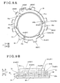
- the power bus bar 82 includes the three recessed bus bar engagement portions 732b (73b) which engage with the base engagement portions 91 a, 91 b and 91 c of the base portion 90.
- the base engagement portions 91 d and 91 e of the base portion 90 are configured not to engage with the power bus bar 82.
- an upper end surface 82a of the power bus bar 82 and an upper surface 910a of the base engagement portion 91 a are coplanar with each other.
- the base engagement portion 91 a is inhibited from protruding from the upper end surface 82a of the power bus bar 82.
- the height of the base engagement portion 91 a in the axial direction is substantially equal to the height of the base engagement portion 91 d in the axial direction.
- Each of the base engagement portions 91 d and 91 e serves as an example of a phase bus bar non-engagement protrusion.
- the bus bar terminals 85 and the power supply terminals 86 are omitted.
- the power bus bar 81 includes the two recessed bus bar engagement portions 731 b (73b) which engage with the base engagement portions 91 b and 91 c of the base portion 90.
- the base engagement portion 91 e of the base portion 90 is configured not to engage with the power bus bar 81.
- the power bus bar 81 covers a portion of the base engagement portion 91 d.
- an upper end surface 81 a of the power bus bar 81 and an upper end surface 910b of the base engagement portion 91 b are coplanar with each other.
- the base engagement portion 91 b is inhibited from protruding from the upper end surface 81 a of the power bus bar 81.
- the bus bar terminals 85 and the power supply terminals 86 are omitted.
- the power bus bar 83 includes the single recessed bus bar engagement portion 733b (73b) which engages with the base engagement portion 91 c of the base portion 90.
- the base engagement portion 91 e of the base portion 90 is configured not to engage with the power bus bar 83.
- an upper end surface 83a of the power bus bar 83 and an upper end surface 910c of the base engagement portion 91 c are coplanar with each other.
- the base engagement portion 91 c is inhibited from protruding from the upper end surface 83a of the power bus bar 83.
- the height of the base engagement portion 91 c in the axial direction is substantially equal to the height of the base engagement portion 91 e in the axial direction.
- an axial height (height in the axial direction) of the base engagement portion 91 c is greater than an axial height (height in the axial direction) of the base engagement portion 91 b, and the axial height of the base engagement portion 91 b is greater than an axial height (height in the axial direction) of the base engagement portion 91 a.
- the power bus bars 82, 81 and 83 are placed in order (in the mentioned order) at an upper portion of the base portion 90 from the lower side in the axial direction.
- the base engagement portions 91 a, 91b and 91 c include the heights h2, h3 and h4, respectively, from the surface 90b of the base portion 90.
- the height h2 is the smallest and the height h4 is the largest.
- the height h3 is specified between the height h2 and the height h4.
- the number of the bus bar engagement portions 732b is greater than the number of the bus bar engagement portions 731 b while the number of the bus bar engagement portions 731 b is greater than the number of the bus bar engagement portion 733b.
- the power bus bar 82 includes the three bus bar engagement portions 732b.
- the power bus bar 81 includes the two bus bar engagement portions 731 b.
- the power bus bar 83 includes the single bus bar engagement portion 733b.
- the axial height of each of the base engagement portions 91 d and 91 e is specified to be greater than an axial height of a lower end surface of at least one of the power bus bars 81 to 83. Specifically, as illustrated in Fig. 8B , the axial height of each of the base engagement portions 91 d and 91 e is greater than an axial height of a lower end surface 82b of the power bus bar 82.
- the base portion 90 includes the base engagement portions 91 a, 91 b and 91 c engaging with the power bus bars 81 to 83 and includes the base engagement portions 91 d and 91 e not engaging with the power bus bars 81 to 83.
- the neutral point bus bar 84 includes the predetermined number of the bus bar engagement portions 73b which are configured to engage with both the base engagement portions 91 a, 91 b, 91 c, and the base engagement portions 91 d, 91 e. Specifically, each of the base engagement portions 91 d and 91 e is inhibited from engaging with the power bus bars 81 to 83.
- the base engagement portions 91 a, 91b and 91 c serve as examples of phase bus bar engagement protrusions.
- the number of the bus bar engagement portions 73b provided at the neutral point bus bar 84 is greater than the number of the bus bar engagement portions 73b provided at each of the power bus bars 81 to 83.
- the neutral point bus bar 84 includes the six bus bar engagement portions 73b while the power bus bars 81 to 83 include the two, three and one bus bar engagement portions 73b respectively.
- the axial height of the base engagement portion 91 d is specified to be greater than the axial height of the lower end surface 82b of the power bus bar 82 and is specified to be equal to or smaller than an axial height of the upper end surface 82a of the power bus bar 82.
- the axial height of the base engagement portion 91 d is substantially the same as the axial height of the upper end surface 82a of the power bus bar 82.
- the bus bar terminals 85 and the power supply terminals 86 are omitted.
- the axial height of the base engagement portion 91 e is specified to be greater than an axial height of a lower end surface 83b of the power bus bar 83.
- the axial height of the base engagement portion 91 e is substantially the same as an axial height of the upper end surface 83a of the power bus bar 83.
- the bus bar terminals 85 and the power supply terminals 86 are omitted.
- the thin plate of each of the bus bars 81 to 83 is bent to the axially upper side so as to obtain the two bus bar terminals 85.
- the two bus bar terminals 85 of each of the bus bars 81 to 83 are provided to make contact with radially inner side surfaces of the corresponding power terminals 101.
- the two bus bar terminals 85 are configured to join by welding to the corresponding power terminals 101.
- the bus bar terminals 85 are configured to join to the U-phase power terminals 101 a and 101 b.
- the power supply terminal 86 connected to the external connection terminal 13 is provided at each of the power bus bars 81 to 83.
- Each of the power bus bars 81 to 83 is therefore configured to transmit an electric power from the external connection terminal 13 to the windings 50.
- the thin plate of the neutral point bus bar 84 is bent to the axially upper side so as to obtain the six bus bar terminals 85.
- the six bus bar terminals 85 are configured to join by welding to the respective neutral point terminals 102.
- the bus bar engagement portions 73b engage with the base engagement portions 91 so that the power bus bars 81 to 83 are assembled on the base portion 90 at a predetermined phase (at a predetermined rotation direction position).
- a predetermined phase at a predetermined rotation direction position.
- each of the power bus bars 81 to 83 is restrained from being assembled in a wrong phase.
- possibility of connection failure between the power bus bars 81 to 83 and the windings 50 may decrease.
- bus bars 81 to 84 where the bus bar engagement portion 73b is not provided at a portion corresponding to the position of the base engagement portion 91 which is inhibited from protruding in the axial direction because of the engagement with the bus bar engagement portion 73b of any other of the bus bars 81 to 84 may be placed upon any other of the bus bars 81 to 84.
- any one of the bus bars 81 to 84 where the bus bar engagement portion 73b is provided so as to engage with the base engagement portion 91 serving as a predetermined base engagement portion which is inhibited from protruding in the axial direction because of the engagement with the aforementioned bus bar engagement portion 73b, and any other of the bus bars 81 to 84 where the bus bar engagement portion 73b is not provided for the engagement with the aforementioned predetermined base engagement portion are assembled in the mentioned order.
- the bus bars 81 to 84 are restrained from being assembled in a wrong order and possibility of connection failure between the power bus bars 81 to 83 and the windings 50 may decrease.
- the bus bars 81 to 84 are restrained from being assembled in the wrong order and possibility of connection failure between the power bus bars 81 to 83 and the windings 50 may decrease.
- the power bus bars 82, 81 and 83 may interfere with at least one of the plural base engagement portions 91 in a case where the power bus bars 82, 81 and 83 are assembled in the wrong order.
- the bus bars 81 to 84 are restrained from being assembled in the wrong order and possibility of connection failure between the power bus bars 81 to 83 and the windings 50 may decrease.
- the power bus bars 82, 81 and 83 are sequentially assembled or placed in the mentioned order from the lower side in the axial direction, the number of the base engagement portions 91 protruding from the upper end surfaces of the respective power bus bars 82, 81 and 83 decreases and the number of the bus bar engagement portions 73b decreases. Consequently, the power bus bars 81 to 83 are restrained from being assembled in the wrong phase (wrong rotation direction position). In addition, the power bus bars 81 to 83 are restrained from being assembled in the wrong order.
- the base engagement portion 91 d or 91 e protrudes from the surface of the aforementioned one of the power bus bars 82, 81 and 83.
- at least one of the power bus bars 82, 81 and 83 is restrained from being assembled in the wrong phase (wrong rotation direction position).
- the bus bar engagement portion 73b is not provided at a portion corresponding to a portion where the base engagement portion 91 d or 91 e protrudes from the surface of at least one of the power bus bars 82, 81 and 83, assembly of the aforementioned one of the power bus bars 82, 81 and 83 where the bus bar engagement portion 73b is not provided may be impossible.
- the power bus bars 81 to 83 are therefore restrained from being assembled in the wrong order.
- the first embodiment is not limited to have the aforementioned construction and may be appropriately modified or changed.
- the windings 50 are connected in the Y-connection as an example.
- the windings may be connected in a delta-connection, for example.
- the two bus bar terminals 85 are provided at each of the power bus bars 81 to 83.
- three or more than three bus bar terminals may be provided at each of the power bus bars.
- the number of the base engagement portions 91 of the base portion 90 is six.
- the number of base engagement portions of the base portion may be eight, for example.
- the power bus bar 82 serves as the U-phase bus bar.
- the power bus bar 83 serves as the V-phase bus bar while the power bus bar 81 serves as the W-phase bus bar.
- the power bus bar 81 may serve as the V-phase bus bar or the U-phase bus bar, for example.
- the following construction may be also obtainable in the motor 100 serving as the rotary electric machine according to the first embodiment.
- plural bus bars include a common bus bar in an annular form and a phase bus bar in an arc form.
- a bus bar holder includes a phase bus bar engagement protrusion which engages with the phase bus bar and a phase bus bar non-engagement protrusion which is inhibited from engaging with the phase bus bar.
- the common bus bar in the annular form includes a predetermined number of bus bar engagement portions, the bus bar engagement portions of the common bus bar being configured to engage with both the phase bus bar engagement protrusion and the phase bus bar non-engagement protrusion.
- the common bus bar engages with both the phase bus bar engagement protrusion and the phase bus bar non-engagement protrusion.
- the common bus bar may be assembled before the phase bus bar is assembled.
- the plural bus bars include the common bus bar in the annular form and the phase bus bar in the arc form.
- the number of the bus bar engagement portions provided at the common bus bar is specified to be greater than the number of bus bar engagement portions provided at the phase bus bar.
- the number of the bus bar engagement portions provided at the common bus bar is specified to be greater than the number of the bus bar engagement portions provided at the phase bus bar, possibility of incapable assembly of the common bus bar on the bus bar holder caused by non-engagement between the bus bar engagement portion of the common bus bar and a holder engagement portion provided at the bus bar holder may be restrained.
- a first phase bus bar, a second phase bus bar and a third phase bus bar are assembled in the mentioned order from the lower side in the axial direction onto the bus bar holder.
- An axial height of the phase bus bar non-engagement protrusion is specified to be greater than an axial height of a lower end surface of the first phase bus bar and specified to be equal to or smaller than an axial height of an upper end surface of the first phase bus bar in a state where a first protrusion, a second protrusion and a third protrusion provided at the bus bar holder engage with a first recess, a second recess, and a third recess provided at the first phase bus bar, the second phase bus bar and the third phase bus bar, respectively.
- the phase bus bar non-engagement protrusion protrudes from the lower end surface of the first phase bus bar in a state where the first phase bus bar is assembled.
- the second phase bus bar and the third phase bus bar are unable to be assembled before the first phase bus bar is assembled.
- the phase bus bars are restrained from being assembled in a wrong order.
- the first phase bus bar is restrained from being assembled in the wrong phase. That is, an end portion of the first phase bus bar interferes with the phase bus bar non-engagement protrusion, which may restrain the first phase bus bar from being wrongly assembled.
- the first phase bus bar, the second phase bus bar and the third phase bus bar are assembled in the mentioned order from the lower side in the axial direction onto the bus bar holder.
- the axial height of the phase bus bar non-engagement protrusion is specified to be greater than the axial height of the lower end surface of the third phase bus bar in a state where the first protrusion, the second protrusion and the third protrusion provided at the bus bar holder engage with the first recess, the second recess, and the third recess provided at the first phase bus bar, the second phase bus bar and the third phase bus bar, respectively.
- the phase bus bar non-engagement protrusion protrudes from the lower end surface of the third phase bus bar in a state where the third phase bus bar is assembled.
- the movement of each of the first to third phase bus bars in the circumferential direction may be restricted by the phase bus bar non-engagement protrusion.
- Each of the first to third phase bus bars is restrained from being assembled in the wrong phase. That is, the end portion of each of the first to third phase bus bars interferes with the phase bus bar non-engagement protrusion, which may restrain the first to third phase bus bars from being assembled in the wrong phase.
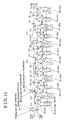
- the windings 50 include common phase crossover wire portions 61 and different phase crossover wire portions 62.
- Each of the common phase crossover wire portions 61 and the different phase crossover wire portions 62 connects each winding start portion 54 (i.e., 54A, 54B, 54C, 54D, 54E, 54F, 54G, 54H, 54I, 54J, 54K or 54L) of one of the windings 50 and each winding end portion 55 (i.e., 55A, 55B, 55C, 55D, 55E, 55F, 55G, 55H, 55I, 55J, 55K or 55L) of another one of the windings 50.
- Each of the common phase crossover wire portions 61 serves as an example of a crossover wire portion.
- Each of the different phase crossover wire portions 62 serves as an example of the crossover wire portion.
- the common phase crossover wire portions 61 are connected to power terminals 71 serving as examples of terminal members and power connection terminals.
- the different phase crossover wire portions 62 are connected to neutral point terminals 72 serving as examples of the terminal members and neutral point connection terminals.
- Each of the power terminal 71 and the neutral point terminal 72 also serves as an example of the winding connection terminal.
- the power terminals 71 and the neutral point terminals 72 are connected to respective ends of the windings 50.
- each of the common phase crossover wire portions 61 is configured to connect between the two windings 50 in the four windings 50, the two windings serving as the same phase windings.
- Two of the common phase crossover wire portions 61 are provided for each phase of the three-phase voltage. That is, the common phase crossover wire portions 61 include two U-phase crossover wire portions 61 a, 61 b, two V-phase crossover wire portions 61 c, 61 d, and two W-phase crossover wire portions 61 e, 61f.
- the U-phase crossover wire portion 61 a is configured to connect the winding start portion 54A of the U-phase winding 51 a serving as one of the U-phase windings and the winding end portion 55J of the U-phase winding 51 d serving as another one of the U-phase winding.
- each of the other common phase crossover wire portions 61 (61 b to 61f) is configured to connect the winding start portion 54 (54B to 54L) of one of the windings 50 and the winding end portion 55 (55B to 55L) of another one of the windings 50, one of the windings 50 and another one of the windings 50 serving as the same phase windings.
- the two power terminals 71 are provided for each phase of the three-phase voltage so as to conform to the number of the common phase crossover wire portions 61.
- the power terminals 71 include U-phase power terminals 71 a, 71 b, V-phase power terminals 71 c, 71 d, and W-phase power terminals 71 e, 71 f.
- the U-phase crossover wire portions 61 a and 61 b are connected to the U-phase power terminals 71 a and 71 b, respectively.
- the V-phase crossover wire portions 61 c and 61 d are connected to the V-phase power terminals 71 c and 71 d, respectively.
- the W-phase crossover wire portions 61 e and 61f are connected to the W-phase power terminals 71 e and 71f, respectively.
- each of the different phase crossover wire portions 62 is configured to connect the winding start portion 54 of one of the windings 50 and the winding end portion 55 of another one of the windings 50 wound at the tooth 22 adjacent to the tooth 22 at which the aforementioned one of the windings 50 is wound, the aforementioned one of the windings 50 and another one of the windings 50 serving as the different phase windings from each other.
- the different phase crossover wire portions 62 include different phase crossover wire portions 62a, 62b, 62c, 62d, 62e and 62f.
- the different phase crossover wire portion 62a is configured to connect the winding start portion 54B of the V-phase winding 52a and the winding end portion 55A of the U-phase winding 51 a serving as the different phase winding from the V-phase winding 52a, the U-phase winding 51 a being wound at the tooth 22 with no. 1 adjacent to the tooth 22 with no. 2 at which the V-phase winding 52a is wound.
- each of the different phase crossover wire portions 62b, 62c, 62d, 62e and 62f is configured to connect the winding start portion 54 of the winding 50 for one of the three phases and the winding end portion 55 of the winding 50 for another one of the three phases wound at the tooth 22 adjacent to the tooth 22 at which the winding 50 for the aforementioned one of the three phases is wound.
- the neutral point terminals 72 include neutral point terminals 72a, 72b, 72c, 72d, 72e and 72f.
- the different phase crossover wire portions 62a to 62f are connected to the neutral point terminals 72a to 72f, respectively.
- the common phase crossover wire portions 61, the different phase crossover wire portions 62 and the windings 50 are obtained by a first wire 63 and a second wire 64 which are continuously provided and each of which serves as a continuous wire.
- the teeth 22 with nos. 1, 2, 5, 6, 9 and 10 constitute a first teeth group 22a.
- the first wire 63 is continuously wound at the first teeth group 22a so as to obtain the common phase crossover wire portions 61, the different phase crossover wire portions 62 and the windings 50.
- the teeth 22 with nos. 3, 4, 7, 8, 11 and 12 constitute a second teeth group 22b.
- the second wire 64 is continuously wound at the second teeth group 22b to obtain the common phase crossover wire portions 61, the different phase crossover wire portions 62 and the windings 50.
- the first wire 63 is configured to start its winding (wiring) at the U-phase power terminal 71 a upon forming the common phase crossover wire portions 61, the different phase crossover wire portions 62 and the windings 50, and thereafter to finish the winding at the U-phase power terminal 71 a.
- the second wire 64 is configured to start its winding (wiring) at the W-phase power terminal 71 e upon forming the common phase crossover wire portions 61, the different phase crossover wire portions 62 and the windings 50, and thereafter to finish the winding at the W-phase power terminal 71 e.
- the motor 100 includes the power bus bars 81, 82 and 83 each of which serves as the bus bar.
- the power bus bar 81 is connected to the U-phase power terminals 71 a and 71 b.
- the power bus bar 82 is connected to the V-phase power terminals 71 c and 71 d.
- the power bus bar 83 is connected to the W-phase power terminals 71e and 71f.
- the power bus bars 81 to 83 are also connected to the respective external connection terminals 13 (see Fig. 1 ).
- the motor 100 also includes the neutral point bus bar 84 which is connected to all the neutral point terminals 72 (specifically, neutral point terminals 72a, 72b, 72c, 72d, 72e and 72f). As a result, a three-phase and four-parallel Y connection is obtained in the motor 100.
- the insulator 40 is provided to cover the plural teeth 22 of the stator core 20 and is configured to insulate between the stator core 20 and the plural windings 50.
- the insulator 40 is made of resin including insulation properties.
- the insulator 40 includes a configuration conforming to a surface configuration of the stator core 20.
- the insulator 40 includes a void at an inside at which the stator core 20 is arranged.
- the insulator 40 includes an opening portion 40a at an axially lower side (i.e., in an arrow Z2 direction).
- the insulator 40 is configured to be mounted to the stator core 20 from the axially upper side.
- the insulator 40 includes an annular configuration when viewed in the axial direction.
- the insulator 40 is configured so that the rotor core 30 (see Fig. 2 ) is arranged at an inner portion of the annular configuration.
- the insulator 40 includes a teeth cover portion 41 covering the teeth 22.
- the windings 50 are wound at the teeth 22 via the teeth cover portion 41.
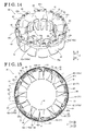
- the insulator 40 includes crossover wire arrangement portions 42 at which the common phase crossover wire portions 61 are arranged at the outer circumferential side of the stator core 20 when viewed in the axial direction (when viewed in the arrow Z1 direction).
- each of the crossover wire arrangement portions 42 is provided at an outer circumferential portion of the insulator 40.
- the crossover wire arrangement portion 42 includes a flange portion 42a disposed at a lower wide in the axial direction (i.e., in the arrow Z2 direction) than the power terminal 71 and the neutral point terminal 72.
- the common phase crossover wire portion 61 is arranged along the flange portion 42a.
- the flange portion 42a is disposed at the axially upper side (i.e., in the arrow Z1 direction) of the back yoke 21 of the stator core 20. That is, the flange portion 42a is arranged at the outer circumferential side of the teeth 22 and at the inner side than an outer circumference of the back yoke 21.
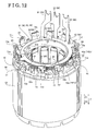
- the insulator 40 includes terminal attachment portions 43 at which the power terminals 71 and the neutral point terminals 72 are configured to be attached.
- the twelve terminal attachment portions 43 are provided at substantially equal angular intervals in the circumferential direction at the outer circumferential portion of the insulator 40 and between the adjacent teeth 22 respectively.
- the terminal attachment portions 43 include respective openings at the axially upper side so that the power terminals 71 and the neutral point terminals 72 are mounted from the axially upper side to the terminal attachment portions 43 as illustrated in Fig. 12 .
- the flange portions 42a are arranged at the axially lower side (arrow Z2 side) than the power terminals 71 and the neutral point terminals 72.
- Respective portions of the power terminals 71 and the neutral point terminals 72 are bent to the axially upper side (arrow Z1 direction) to obtain wire joint portions 73 each of which is in a hook form.
- the wire joint portion 73 is connected to the common phase crossover wire portion 61 or the different phase crossover wire portion 62 by fusing welding. Therefore, the power terminal 71 and the common phase crossover wire portion 61 are joined at the wire joint portion 73 while the neutral point terminal 72 and the different phase crossover wire portion 62 are joined at the wire joint portion 73.
- the winding 50 is configured to be connected to the power terminal 71 or the neutral point terminal 72 in a state where the winding start portion 54 of one of the windings 50 and the winding end portion 55 of another one of the windings 50 are connected to each other.
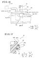
- the insulator 40 includes a crossover wire restriction portion 44 serving as an example of a first restriction portion and a second restriction portion which restricts a wiring position between the common phase crossover wire portions 61 for different phases of the three-phase voltage.
- the common phase crossover wire portions 61 include a first common phase crossover wire portion 65 (for example, the U-phase crossover wire portion 61 b, the V-phase crossover wire portion 61 d or the W-phase crossover wire portion 61 e) which is disposed from the flange portion 42a to the power terminal 71 (power terminal 71 b, 71 d or 71 e) for one of the phases of the three-phase voltage.
- the crossover wire restriction portion 44 includes a first hook portion 44a serving as an example of the first restriction portion arranged at a height position (i.e., height position in a direction parallel to a Z-axis direction) between the flange portion 42a and the power terminal 71 to restrict a height position of the first common phase crossover wire portion 65.
- the first hook portion 44a is disposed between the two flange portions 42a, i.e., a first flange portion 142a and a second flange portion 242a, in the circumferential direction. As illustrated in Fig. 17 , the first hook portion 44a is formed in a U-shape (hook shape) opening to the axially lower side (Z2 direction) and radially outer side (arrow A1 side).
- the first common phase crossover wire portion 65 is arranged over an upper surface of the first flange portion 142a, the axially lower side of the first hook portion 44a and the axially upper side of the wire joint portion 73 in the hook form of the power terminal 71 so that the height position of the first common phase crossover wire portion 65 is restricted.
- the hook portion 44a is in contact with the first common phase crossover wire portion 65 as illustrated in Fig. 17 so that not only the height position but also a position in the radial direction (i.e., arrow A1 and A2 directions) of the first common phase crossover wire portion 65 is restricted.
- the common phase crossover wire portions 61 also include a second common phase crossover wire portion 66 (for example, the U-phase crossover wire portion 61 a, the V-phase crossover wire portion 61 c or the W-phase crossover wire portion 61f) connected to the power terminal 71 (power terminal 71 a, 71 c or 71 f) for another one of the phases of the three-phase voltage and disposed from one of the teeth 22 (see Fig. 13 ) to the second flange portion 242a.
- the crossover wire restriction portion 44 includes a restriction portion 44b restricting a height position of the second common phase crossover wire portion 66 in a state where the first common phase crossover wire portion 65 and the second common phase crossover wire portion 66 are separated from each other in the radial direction.
- the restriction portion 44b includes a protruding portion 44c protruding to the axially upper side (Z1 side) from the first hook portion 44a and to one side in the circumferential direction (i.e., towards the first flange portion 142a).
- the second common phase crossover wire portion 66 disposed to the radially outer side from one of the teeth 22 is arranged along a circumferential one side surface 144b of the restriction portion 44b at the axially lower side of the protruding portion 44c. As illustrated in Fig.
- the second common phase crossover wire portion 66 is arranged, making contact with an axially upper side of an upper surface 144a of the first hook portion 44a and extending along a radially outer surface 244b of the restriction portion 44b.
- the second common phase crossover wire portion 66 is disposed at the radially outer side than the first common phase crossover wire portion 65 and at the height position at the axially upper side than the first common phase crossover wire portion 65.
- the second common phase crossover wire portion 66 is disposed at the second flange portion 242a accordingly.
- the crossover wire arrangement portion 42 includes a guide portion 42b at which the common phase crossover wire portion 61 disposed from the power terminal 71 to one of the teeth 22 is arranged.
- the guide portion 42b is provided so as to protrude to the axially upper side from the flange portion 42a.
- the common phase crossover wire portion 61 is disposed from the wire joint portion 73 of the power terminal 71 to one of the teeth 22 via the guide portion 42b, i.e., while making contact with a surface of the guide portion 42b.
- the motor 100 includes a base portion 93 which is arranged at the axially upper side of the insulator 40 and which includes an annular configuration, and three insulation members 94 disposed between the power bus bars 81 to 83, respectively, in the axial direction.
- the base portion 93 serves as an example of the bus bar holder.
- the base portion 93 is made of resin, for example, including insulation properties.
- the base portion 93 is arranged at the axially upper side of the position at which the teeth 22 of the stator core 20 are provided and at the upper side of the insulator 40 at which the windings 50 are wound.
- Each of the power bus bars 81 to 83 is formed in a thin plate and an arc form.
- the neutral point bus bar 84 is formed in a thin plate and an annular form.
- the insulation members 94 are made of resin, for example, and are arranged between the neutral point bus bar 84, the power bus bars 81, 82 and 83, respectively, in the axial direction so as to insulate therebetween.
- the base portion 93, the neutral point bus bar 84, the insulation member 94, the power bus bar 82, the insulation member 94, the power bus bar 81, the insulation member 94 and the power bus bar 83 are assembled in the mentioned order from a lower side in the axial direction.
- the base portion 93 includes base engagement portions 93a each of which is in a protruding form.
- the base engagement portions 93a are configured to engage with bus bar engagement portions 93b, each of which is in a recess form, provided at the power bus bars 81 to 83 and with the insulation engagement portions 94a, each of which is in a recess form, provided at the insulation members 94. Consequently, positions of the neutral point bus bar 84, the power bus bars 81 to 83 in the circumferential direction are restricted.
- the base engagement portion 93a serves as an example of the holder engagement portion.
- Each of the power bus bars 81 to 83 formed in a thin plate is bent to the axially upper side to obtain the two bus bar terminals 85.
- the two bus bar terminals 85 are provided to make contact with radially inner side surfaces of the corresponding power terminals 71.
- the two bus bar terminals 85 are configured to join by welding to the corresponding power terminals 71.
- the bus bar terminals 85 are configured to join to the U-phase power terminals 71 a and 71 b.
- the power supply terminal 86 connected to the external connection terminal 13 is provided at each of the power bus bars 81 to 83.
- Each of the power bus bars 81 to 83 is therefore configured to transmit an electric power from the external connection terminal 13 to the windings 50.
- the neutral point bus bar 84 formed in a thin plate is bent to the axially upper side so as to obtain the six bus bar terminals 85.
- the six bus bar terminals 85 are configured to join by welding to the respective neutral point terminals 72.
- the winding start portion 54 of one of the windings 50 and the winding end portion 55 of another one of the windings 50 may be connected to the common power terminal 71 (or the neutral point terminal 72) so that the number of the power terminals 71 (or the neutral point terminals 72) for the single winding 50 (specifically, winding 50 wound at each of the teeth 22) is one. Accordingly, as compared to a case where the two terminal members (the terminal members corresponding to the power terminal and the neutral point terminal) are provided for the single winding, the number of the power terminals 71 and the neutral point terminals 72 may decrease by half.
- the number of welding for connecting the windings 50 to the power terminals 71 and the neutral point terminals 72 may decrease by half.
- the number of the power terminals 71 and the neutral point terminals 72 decreases by half and the number of manufacturing processes of the motor 100 may decrease.
- the common phase crossover wire portion 61 is disposed at the crossover wire arrangement portion 42 so as to connect the aforementioned two windings 50.
- the crossover wire arrangement portion 42 is provided at the insulator 40, so that an exclusive member for arranging the common phase crossover wire portion 61 is not necessary, which restrains the increase of the number of components.
- the height position of the first common phase crossover wire portion 65 may be restricted to a predetermined height position by the first hook portion 44a.
- the first common phase crossover wire portion 65 and the second common phase crossover wire portion 66 in which different phase voltages are induced are arranged separating from each other.
- interference or short-circuit may be restrained from occurring between the first common phase crossover wire portion 65 and the second common phase crossover wire portion 66.
- the number of welding for connecting the power terminals 71 to the power bus bars 81 to 83 may decrease by half as compared to a case where the two power terminals 71 are provided for the single winding 50. As a result, the number of manufacturing processes may decrease.
- the winding start portion 54 of one of the windings 50 and the winding end portion 55 of another one of the windings 50 are connected to the common neutral point terminal 72.
- the neutral point terminal 72 is provided at either the winding start portion 54 or the winding end portion 55 of each of the windings 50, the number of the neutral point terminals 72 may decrease by half.
- the common phase crossover wire portion 61 and the different phase crossover wire portion 62 are continuously formed to the winding 50 after the winding 50 is wound at each of the teeth 22.
- the common phase crossover wire portion 61 and the different phase crossover wire portion 62 are obtained by connection of separate wires from one another, the number of components and the number of manufacturing processes are restrained from increasing.
- the crossover wire arrangement portion 42 and the power terminal 71 may be easily connected to each other.
- the terminal attachment portion 43 is provided at the insulator 40, an exclusive member for mounting the power terminal 71 (or the neutral point terminal 72) to the motor 100 is not necessary, which restrains the number of components from increasing.
- all the windings 50, the common phase crossover wire portions 61 and the different phase crossover wire portions 62 are obtainable by the two wires corresponding to the first wire 63 and the second wire 64. That is, all the windings 50, the common phase crossover wire portions 61 and the different phase crossover wire portions 62 are obtainable by two times of wiring (winding) process.
- the common phase crossover wire portions 61 and the different phase crossover wire portions 62 are obtained by three or more than three wires, for example, the number of manufacturing processes may be effectively restrained.
- the second embodiment is not limited to have the aforementioned construction and may be appropriately modified or changed.
- the motor 100 is constructed as an 8-pole 12-slot motor.
- the motor 100 may be constructed to include the number of poles other than eight and to include the number of slots other than twelve.
- the insulator 40 is provided at the motor 100.
- the insulator 40 may not be provided at the motor 100.
- the windings 50 may be directly wound at the stator core 20.
- the crossover wire arrangement portion 42 is integrally provided at the insulator 40.
- the crossover wire arrangement portion 42 may be provided as a separate member from the insulator 40.
- the windings 50, the common phase crossover wire portions 61 and the different phase crossover wire portions 62 are obtained by the continuously formed first wire 63 (or the second wire 64).
- the windings 50, the common phase crossover wire portions 61 and the different phase crossover wire portions 62 may be obtained by separate wires from one another.
- the power bus bar 81 serves as the U-phase bus bar. Then, the power bus bar 82 serves as the V-phase bus bar while the power bus bar 83 serves as the W-phase bus bar. Alternatively, the power bus bar 81 may serve as the V-phase bus bar or the W-phase bus bar, for example.
- the following construction may be also obtainable in the motor 100 serving as the rotary electric machine according to the second embodiment.
- the insulator may include the terminal attachment portion which is provided in the vicinity of the crossover wire arrangement portion and at which the terminal member is attachable.
- the crossover wire arrangement portion and the terminal member may be easily connected.
- the terminal attachment portion is provided at the insulator, an exclusive member for attaching the terminal member at the motor is not necessary, which restrains the number of components from increasing.
- the plural teeth are constituted by the first teeth group including the teeth and the second teeth group including the teeth other than those of the first teeth group.
- the wire may include the first wire wound at the first teeth group to obtain the windings and the crossover wire portions and the second wire wound at the second teeth group to obtain the windings and the crossover wire portions.
- all the windings wound at the plural teeth and the crossover wire portions are achieved by the two wires, i.e., the first wire and the second wire, so that all the windings and the crossover wire portions may be obtained by two times of wiring (winding) process. Therefore, as compared to a case where the windings and the crossover wire portions are obtained by three or more than three wires, the increase of the number of manufacturing processes may be effectively restrained.
Abstract
Description
- This disclosure generally relates to a rotary electric machine.
- A known rotary electric machine including plural bus bars is disclosed, for example, in
JP2015-97450A Reference 1. In addition, a known rotary electric machine including concentrated winding coils is disclosed, for example, inJP2013-223322A Reference 2. - The rotary electric machine disclosed in
Reference 1 includes a stator where plural stator pieces are annularly disposed in a circumferential direction relative to an axis of the stator and a rotor disposed coaxially with the stator and facing the stator. The stator pieces are constituted by plural split cores including projecting teeth at which phase coils (windings) are wound respectively, the phase coils corresponding to W-phase coils, V-phase coils and U-phase coils. The stator includes the plural bus bars, specifically, a W-phase bus bar, a V-phase bus bar, a U-phase bus bar and a common bus bar, which supply an electric power to the corresponding phase coils and which are connected to the corresponding stator pieces for the respective phases so as to maintain an annular arrangement of the split cores. Each of the W-phase bus bar, the V-phase bus bar, the U-phase bus bar and the common bus bar is formed in an annular plate. The W-phase bus bar, the V-phase bus bar and the U-phase bus bar are disposed at positions corresponding to the W-phase coils, the V-phase coils and the U-phase coils, respectively. - The rotary electric machine disclosed in
Reference 2 includes a stator core including twelve teeth. The concentrated winding coils are constituted as three-phase alternating current windings in a state where the four concentrated winding coils are connected in parallel to one another for each phase. The concentrated winding coil wound at each of the teeth includes a coil terminal at each of a winding start portion and a winding end portion. That is, the two coil terminals are provided at each of the teeth. As a result, the twenty-four coil terminals in total are provided at the rotary electric machine. In addition, the rotary electric machine includes three bus bars each of which includes four coil connection terminals and one bus bar for a neutral point connection including twelve coil connection terminals. In the rotary electric machine disclosed inReference 2, the coil terminals of the concentrated winding coils and the coil connection terminals of the bus bars are connected by welding to thereby achieve a Y-connection of the concentrated winding coils. - According to the rotary electric machine disclosed in
Reference 1, in a case where each of the bus bars is assembled on the stator, the bus bar may be assembled in a wrong phase (wrong rotation direction position), which may lead to a connection failure between the bus bar and the phase coils. According to the rotary electric machine disclosed inReference 2, the coil terminals (terminal members) are provided at the winding start portion and the winding end portion of each of the concentrated winding coils wound at the teeth. Thus, the two terminal members are necessary for each of the concentrated winding coils wound at the teeth. In a case of assembling the rotary electric machine, the number of welding for connecting the concentrated winding coils and the terminal members is required for the number of the terminal members. As a result, the number of welding (number of manufacturing processes) may be relatively large. - A need thus exists for a rotary electric machine which restrains each bus bar from being assembled in a wrong phase, i.e., at a wrong rotation direction position, and which decreases possibility of connection failure between each bus bar and phase coils. In addition, a need thus exists for the rotary electric machine where the number of terminal members is reduced and the number of manufacturing processes is reduced.
- According to a first aspect of this disclosure, a rotary electric machine includes a rotor core fixed at a rotation axis, a stator core arranged facing the rotor core and including a plurality of teeth, a plurality of windings wound at the plurality of teeth of the stator core, a plurality of winding connection terminals connected to respective ends of the plurality of windings, a plurality of bus bars connected to the plurality of winding connection terminals, each of the plurality of bus bars being formed in either an arc form or an annular form, and a bus bar holder holding the plurality of bus bars in a laminated state and including a holder engagement portion engaging with a bus bar engagement portion which is provided at least at one of the plurality of bus bars.
- According to the aforementioned first aspect, the bus bar engagement portion engages with the holder engagement portion so that each of the bus bars is assembled on the bus bar holder at a predetermined phase (at a predetermined rotation direction position). Thus, each of the bus bars is restrained from being assembled in a wrong phase. In addition, possibility of connection failure between the bus bars and the windings may decrease.
- In certain embodiments, the holder engagement portion includes a plurality of protrusions which include different heights from one another in a rotation axis direction of the rotor core. At least one of the plurality of protrusions is configured to be inhibited from protruding in the rotation axis direction by engaging with the bus bar engagement portion provided at least at one of the plurality of bus bars.
- Accordingly, any one of the bus bars where the bus bar engagement portion is not provided at a portion corresponding to the position of the holder engagement portion which is inhibited from protruding in the axial direction because of the engagement with the bus bar engagement portion of any other of the bus bars may be placed upon any other of the bus bars. That is, any one of the bus bars where the bus bar engagement portion is provided so as to engage with the holder engagement portion serving as a predetermined holder engagement portion which is inhibited from protruding in the axial direction because of the engagement with the aforementioned bus bar engagement portion, and any other of the bus bars where the bus bar engagement portion is not provided for the engagement with the aforementioned predetermined base engagement portion are assembled in the mentioned order. Thus, the bus bars are restrained from being assembled in a wrong order and possibility of connection failure between the bus bars and the windings may decrease.
- In certain embodiments, the plurality of protrusions includes a first protrusion, a second protrusion and a third protrusion, the plurality of bus bars including a first phase bus bar which includes a first recess, a second phase bus bar which includes a second recess and a third phase bus bar which includes a third recess. The first protrusion is inhibited from protruding from the first phase bus bar in a state where the first protrusion and the first recess engage with each other, the second protrusion is inhibited from protruding from the second phase bus bar in a state where the second protrusion and the second recess engage with each other, the third protrusion is inhibited from protruding from the third phase bus bar in a state where the third protrusion and the third recess engage with each other.
- Accordingly, the numbers of protrusions protruding from the first phase bus bar, the second phase bus bar and the third phase bus bar in a case where the first phase bus bar, the second phase bus bar and the third phase bus bar are assembled respectively are different from one another. Thus, the first to third phase bus bars are restrained from being assembled in the wrong order and possibility of connection failure between the first to third phase bus bars and the windings may decrease.
- In certain embodiments, a height of the third protrusion in the rotation axis direction is greater than a height of the second protrusion in the rotation axis direction while the height of the second protrusion in the rotation axis direction is greater than a height of the first protrusion in the rotation axis direction. The first phase bus bar, the second phase bus bar and the third phase bus bar are configured to be placed in order from a lower side in the rotation axis direction at an upper portion of the bus bar holder.
- Because of the plural protrusions including different heights from one another, the first phase bus bar, the second phase bus bar and the third phase bus bar may interfere with at least one of the plural protrusions in a case where the first phase bus bar, the second phase bus bar and the third phase bus bar are assembled in the wrong order. Thus, by the construction where the first to third phase bus bars are placed in the aforementioned order, the first to third phase bus bars are restrained from being assembled in the wrong order and possibility of connection failure between the first to third phase bus bars and the windings may decrease.
- In certain embodiments, the first recess includes a plurality of first recesses and the second recess includes a plurality of second recesses. Number of the plurality of first recesses is greater than number of the plurality of second recesses, and the number of the plurality of second recesses is greater than number of the third recess.
- Accordingly, while the first phase bus bar, the second phase bus bar and the third phase bus bar are sequentially placed in the mentioned order from the lower side in the axial direction, the number of protrusions protruding from the first phase bus bar, the second phase bus bar and the third phase bus bar decreases and the number of recesses decreases. Consequently, the first to third phase bus bars are restrained from being assembled in the wrong phase (wrong rotation direction position). In addition, the first to third phase bus bars are restrained from being assembled in the wrong order.
- In certain embodiments, the bus bar holder includes a phase bus bar non-engagement protrusion which is inhibited from engaging with any one of the first phase bus bar, the second phase bus bar and the third phase bus bar. Each of the first phase bus bar, the second phase bus bar and the third phase bus bar is formed in an arc form. In a state where the first protrusion, the second protrusion and the third protrusion engage with the first recess portion, the second recess portion and the third recess portion, respectively, a height of the phase bus bar non-engagement protrusion in the rotation axis direction is specified to be greater than a height of a lower end surface of at least one of the first phase bus bar, the second phase bus bar and the third phase bus bar in the axial direction.
- Accordingly, in a case where at least one of the first to third phase bus bars is assembled or mounted, the phase bus bar non-engagement protrusion protrudes from a surface of the aforementioned one of the first to third phase bus bars. Thus, at least one of the first to third phase bus bars is restrained from being assembled in the wrong phase (wrong rotation direction position). In addition, in a case where the bus bar engagement portion is not provided at a portion corresponding to a portion where the phase bus bar non-engagement protrusion protrudes from the surface of at least one of the first to third phase bus bars, assembly of the aforementioned one of the first to third phase bus bars where the bus bar engagement portion is not provided may be impossible. The first to third phase bus bars are therefore restrained from being assembled in the wrong order.
- According to a second aspect of the disclosure, a rotary electric machine includes a rotor core, a stator core arranged facing the rotor core and including a plurality of teeth, a plurality of windings in which a three-phase voltage is induced and which is connected in a Y-connection, the plurality of windings being wound in a concentrated manner at the plurality of teeth of the stator core, a crossover wire portion connecting a winding start portion of one of the plurality of windings and a winding end portion of another one of the plurality of windings, and a terminal member connected to the crossover wire portion.
- According to the second aspect, because of the crossover wire portion, the winding start portion of one of the windings and the winding end portion of another one of the windings may be connected to the common terminal member so that the single power terminal may be provided for the single winding (tooth). Accordingly, as compared to a case where two terminal members are provided for the single winding, the number of terminal members may decrease by half. In addition, because of decrease of the number of terminal members by half, the number of welding for connecting the windings to the terminal members may decrease by half. As a result, the number of terminal members decreases by half and the number of manufacturing processes may decrease.
- In certain embodiments, the rotary electric machine further includes an insulator provided to cover the plurality of teeth to insulate between the stator core and the plurality of windings. The terminal member includes a power connection terminal. The crossover wire portion includes a common phase crossover wire portion which is connected to the power connection terminal to connect between two windings in the plurality of windings, the two windings serving as same phase windings. The insulator includes a crossover wire arrangement portion at an outer circumferential side of the stator core when viewed in an axial direction so that the common phase crossover wire portion is arranged at the crossover wire arrangement portion.
- Accordingly, even in a case where the two windings serving as the same phase windings are wound at the teeth which are away from each other, the common phase crossover wire portion is disposed at the crossover wire arrangement portion so as to connect the aforementioned two windings. The crossover wire arrangement portion is provided at the insulator, so that an exclusive member for arranging the common phase crossover wire portion is not necessary, which restrains the increase of the number of components.
- In certain embodiments, the crossover wire arrangement portion includes a flange portion which is provided at an outer circumferential portion of the insulator and which is disposed at a lower side in the axial direction than the terminal member. The common phase crossover wire portion includes a first common phase crossover wire portion disposed from the flange portion to the power connection terminal for one phase of the three-phase voltage. The insulator includes a first restriction portion arranged at a height position between the flange portion and the power connection terminal to restrict a height position of the first common phase crossover wire portion.
- Accordingly, even in a case where a height position of the crossover wire arrangement portion and a height position of the terminal member are different from each other, a height position of the first common phase crossover wire portion may be restricted to a predetermined height position by the first restriction portion.
- In certain embodiments, the common phase crossover wire portion includes a second common phase crossover wire portion connected to the power connection terminal for the other phase of the three-phase voltage disposed from one of the teeth to the flange portion. The insulator includes a second restriction portion restricting a height position of the second common phase crossover wire portion in a state where the first common phase crossover wire portion and the second common phase crossover wire portion are separated from each other in a radial direction of the rotor core.
- Accordingly, the first common phase crossover wire portion and the second common phase crossover wire portion in which different phase voltages are induced are arranged separating from each other. Thus, interference or short-circuit may be restrained from occurring between the first common phase crossover wire portion and the second common phase crossover wire portion.
- In certain embodiments, the plurality of windings includes four windings serving as same phase windings. The crossover wire portion includes two common phase crossover wire portions each of which connects between the two windings in the four windings serving as the same phase windings. The power connection terminal includes two power connection terminals provided corresponding to the two common phase crossover wire portions. The rotary electric machine further includes a bus bar connected to the two power connection terminals and to an external terminal.
- Accordingly, the number of welding for connecting the power connection terminals to the bus bars may decrease by half as compared to a case where the two terminal members are provided for the single winding. As a result, the number of manufacturing processes may decrease.
- In certain embodiments, the terminal member includes a neutral point connection terminal. The crossover wire portion is configured to connect the winding start portion of one of the plurality of windings and the winding end portion of another one of the plurality of windings, one of the plurality of windings and another one of the plurality of windings serving as different phase windings from each other, the one of the plurality of windings being wound at one of the teeth adjacent to another one of the teeth at which the another one of the plurality of windings is wound, the crossover wire portion being connected to the neutral point connection terminal.
- Accordingly, the winding start portion of one of the windings and the winding end portion of another one of the windings are connected to the common neutral point connection terminal. Thus, as compared to a case where the neutral point connection terminal is provided at either the winding start portion or the winding end portion of each of the windings, the number of neutral point connection terminals may decrease by half.
- In certain embodiments, the crossover wire portion and the windings are obtained by a continuous wire.
- Accordingly, after the winding is wound at each of the teeth, the crossover wire portion may be continuously formed to the aforementioned winding wound at each of the teeth. Thus, being different from a case where the winding and the crossover wire portion are obtained by connection of separate wires from one another, the number of components and the number of manufacturing processes are restrained from increasing.
- The foregoing and additional features and characteristics of this disclosure will become more apparent from the following detailed description considered with the reference to the accompanying drawings, wherein:
-
Fig. 1 is a cross-sectional view of a motor serving as a rotary electric machine according to first and second embodiments disclosed here; -
Fig. 2 is a plan view of a stator core and a rotor core of the motor when viewed in an axial direction according to the first and second embodiments; -
Fig. 3 is a circuit diagram for explaining a winding connection of the motor according to the first and second embodiments; -
Fig. 4 is a perspective view for explaining an inside of the motor according to the first embodiment; -
Fig. 5 is an exploded perspective view of the motor according to the first embodiment; -
Figs. 6A and 6B are a plan view and a side view for explaining the inside of the motor before a neutral point bus bar is mounted according to the first embodiment; -
Figs 7A and 7B are a plan view and a side view for explaining the inside of the motor after the neutral point bus bar is mounted according to the first embodiment; -
Figs. 8A and 8B are a plan view and a side view for explaining the inside of the motor after a power bus bar is mounted according to the first embodiment; -
Figs. 9A and 9B are a plan view and a side view for explaining the inside of the motor after another power bus bar is mounted according to the first embodiment; -
Figs. 10A and 10B are a plan view and a side view for explaining the inside of the motor after still another power bus bar is mounted according to the first embodiment; -
Fig. 11 is a development connection diagram when viewed from a radially inner side of the motor according to the second embodiment disclosed here; -
Fig. 12 is a perspective view for explaining the inside of the motor according to the second embodiment; -
Fig. 13 is a perspective view for explaining a crossover wire portion and a crossover wire arrangement portion of the motor according to the second embodiment; -
Fig. 14 is a perspective view of an insulator of the motor when viewed in the axial direction according to the second embodiment; -
Fig. 15 a plan view of the insulator of the motor when viewed in the axial direction according to the second embodiment; -
Fig. 16 is a side view illustrating a construction of a crossover wire restriction portion of the motor according to the second embodiment; -
Fig. 17 is a cross-sectional view taken along a line XVII-XVII inFig. 16 ; and -
Fig. 18 is an exploded perspective view of the motor according to the second embodiment. - A first embodiment is explained with reference to the attached drawings. A
motor 100 according to the first embodiment is explained with reference toFigs. 1 to 10 . - As illustrated in
Fig. 1 , themotor 100 serving as an example of a rotary electric machine is constituted as a brushless motor. Themotor 100 includes acasing 10, astator core 20 and arotor core 30. Therotor core 30 is disposed at an inner side (i.e., a radially inner side) of thestator core 20 in an annular form so as to face thestator core 20. In the disclosure, a circumferential direction corresponds to a circumferential direction of therotor core 30 or thestator core 20. In addition, a radial direction corresponds to a radial direction of therotor core 30. Further, an axial direction corresponds to a rotation axis direction of therotor core 30. - The
casing 10 is provided to cover an outer peripheral surface of thestator core 20. Thecasing 10 includesbearings rotor core 30 by thebearings external connection terminals 13 each of which serves as an external terminal are provided at thecasing 10. Theexternal connection terminals 13 are supplied or applied with three-phase voltages, specifically, a U-phase voltage, a V-phase voltage and a W-phase voltage, respectively. InFig. 1 , one of theexternal connection terminals 13 is only illustrated. The threeexternal connection terminals 13 are arranged along a direction in parallel to a Y-axis direction. - As illustrated in
Fig. 2 , plural (for example, twelve)teeth 22 are provided at thestator core 20 so as to protrude from aback yoke 21 towards a radially inner side. In addition,slots 23 are provided at thestator core 20 in a manner where each of theslots 23 is disposed between theadjacent teeth 22. Windings 50 (seeFig. 3 ) are wound at the teeth 22 (slots 23) in a concentrated manner (i.e., thewindings 50 serve as concentrated windings) via an insulator 40 (seeFigs. 4 and5 ). InFig. 2 , for easy explanation, the twelveteeth 22 are assigned withdifferent numbers 1 to 12. - Plural (for example, eight)
permanent magnets 31 are embedded in therotor core 30 at substantially equal angular intervals in the circumferential direction. Each of thepermanent magnets 31 includes a substantially rectangular cross section when viewed in the axial direction. Themotor 100 is configured as an 8-pole 12-slot motor accordingly. - As illustrated in
Fig. 3 , thewindings 50 include plural (for example, four)U-phase windings phase windings phase windings U-phase windings phase windings phase windings U-phase windings phase windings phase windings windings 50 are connected in a three-phase and four-parallel Y connection (star connection). In the following, theU-phase windings phase windings phase windings windings 50 in a case where thewindings 51 a to 51 d, 52a to 52d and 53a to 53d are not specifically distinguished from one another. - As illustrated in
Fig. 4 , themotor 100 includes power bus bars 81, 82 and 83. The power bus bars 81 to 83 are connected to power terminals 101 (i.e.,power terminals power bus bar 82 is connected to theU-phase power terminals power bus bar 83 is connected to the V-phase power terminals power bus bar 81 is connected to the W-phase power terminals Fig. 1 ). Themotor 100 includes a neutralpoint bus bar 84. The neutralpoint bus bar 84 is connected to all neutral point terminals 102 (i.e.,neutral point terminals motor 100 is connected in the three-phase and four-parallel Y connection. Thepower bus bar 82 serves as an example of a first phase bus bar. Thepower bus bar 81 serves as an example of a second phase bus bar. Thepower bus bar 83 serves as an example of a third phase bus bar. The neutralpoint bus bar 84 serves as an example of a common bus bar. Each of thepower terminal 101 and theneutral point terminal 102 serves as an example of a winding connection terminal. Thepower terminals 101 and theneutral point terminals 102 are connected to respective ends of thewindings 50. - As illustrated in
Fig. 5 , theinsulator 40 is provided to cover theplural teeth 22 of thestator core 20. Theinsulator 40 is configured to insulate between thestator core 20 and theplural windings 50. - As illustrated in
Fig. 5 , themotor 100 includes abase portion 90 which is arranged at an axially upper side of theinsulator 40 and which includes an annular configuration, and threeinsulation members 74 disposed between the power bus bars 81 to 83, respectively, in the axial direction. Thebase portion 90 serves as an example of a bus bar holder. - Specifically, the
base portion 90 is made of resin, for example, including insulation properties. Thebase portion 90 is arranged at the axially upper side of a position at which theteeth 22 of thestator core 20 are provided and at the upper side of theinsulator 40 at which thewindings 50 are wound. - Each of the power bus bars 81 to 83 is formed in a thin plate and an arc form. The neutral
point bus bar 84 is formed in a thin plate and an annular form. - The
insulation members 74 are made of resin, for example, and are arranged between the neutralpoint bus bar 84, the power bus bars 81, 82 and 83, respectively, in the axial direction so as to insulate therebetween. Thebase portion 90, the neutralpoint bus bar 84, one of the threeinsulation members 74, thepower bus bar 82, another one of the threeinsulation members 74, thepower bus bar 81, still another one of the threeinsulation members 74 and thepower bus bar 83 are assembled in the mentioned order from a lower side in the axial direction (i.e., assembled in an arrow Z1 direction). - As illustrated in
Fig. 6A , base engagement portions 91 (specifically,base engagement portions base portion 90. The power bus bars 81 to 83 include busbar engagement portions 73b (specifically, busbar engagement portions insulation members 74 includeinsulation engagement portions 74a each of which is in a recess form. Thebase engagement portions 91 are configured to engage with the busbar engagement portions 73b of the power bus bars 81 to 83 and theinsulation engagement portions 74a of theinsulation members 74. As a result, positions of the neutralpoint bus bar 84 and the power bus bars 81 to 83 in the circumferential direction are restricted. Thebase engagement portion 91 serves as an example of a holder engagement portion. - The motor 100 (rotary electric machine) includes the power bus bars 81 to 83 each of which is in an arc form and which are connected to the
plural power terminals 101, and the neutralpoint bus bar 84 in an annular form connected to the pluralneutral point terminals 102. In addition, thebase portion 90 includes thebase engagement portions 91 holding the power bus bars 81 to 83 and the neutralpoint bus bar 84 as in a laminated manner and engaging with the busbar engagement portions 73b provided at least at one of the power bus bars 81, 82, 83 and the neutralpoint bus bar 84. Specifically, as illustrated inFig. 5 , thepower bus bar 81 includes the two busbar engagement portions 731 b. Thepower bus bar 82 includes the three busbar engagement portions 732b. Thepower bus bar 83 includes the single busbar engagement portion 733b. The neutralpoint bus bar 84 includes the six busbar engagement portions 73b. As illustrated inFig. 6A , thebase portion 90 includes the sixbase engagement portions 91 which engage with the busbar engagement portions 73b provided at least at one of the power bus bars 81 to 83 and the neutralpoint bus bar 84. For example, as illustrated inFig. 7A , the sixbase engagement portions 91 engage with the six busbar engagement portions 73b of the neutralpoint bus bar 84. - As illustrated in
Fig. 6A , thebase portion 90 includes sixgroove portions 90a. The base engagement portions 91 (specifically, thebase engagement portions respective groove portions 90a. InFigs. 6 to 10 , members other than thebase portion 90, theinsulation members 74, the power bus bars 81 to 83 and the neutralpoint bus bar 84 are omitted. - As illustrated in
Fig. 6B , the pluralbase engagement portions 91 include different heights from one another in the axial direction. At least one of the pluralbase engagement portions 91 engages with the busbar engagement portion 73b of at least one of the plural bus bars 81 to 83 and 84 so as not to protrude in the axial direction. Specifically, thebase engagement portion 91f serving as one of the pluralbase engagement portions 91 protrudes by a height h1 from asurface 90b (i.e., a lower end surface) of thebase portion 90. Each of thebase engagement portions surface 90b. Thebase engagement portion 91 b protrudes by a height h3 which is higher than the height h2 (for example, five times higher than the height h1) from thesurface 90b. Each of thebase engagement portions surface 90b so as to be coplanar with anupper end surface 90c (seeFig. 6A ) of thebase portion 90. As illustrated inFig. 7A , the neutralpoint bus bar 84 includes the six busbar engagement portions 73b which engage with the sixbase engagement portions 91 in a case where the neutralpoint bus bar 84 is placed onto thebase portion 90. As illustrated inFig. 7B , in a case where the neutralpoint bus bar 84 is placed onto thebase portion 90, anupper end surface 84a of the neutralpoint bus bar 84 and anupper end surface 910f of thebase engagement portion 91f are coplanar with each other. In the same manner, in a case where any one of the power bus bars 81 to 83 is placed or mounted onto thebase portion 90, an upper end surface of any one of the power bus bars 81 to 83 is coplanar with an upper end surface of any one of thebase engagement portions Figs. 6B and7B ,bus bar terminals 85 andpower supply terminals 86 are omitted. - In the embodiment, the plural
base engagement portions 91 include thebase engagement portions bar engagement portions base engagement portion 91 a engages with the busbar engagement portion 732b, thebase engagement portion 91 a is inhibited from protruding from thepower bus bar 82 as illustrated inFig. 8B . In a state where thebase engagement portion 91 b engages with the busbar engagement portion 731 b, thebase engagement portion 91 b is inhibited from protruding from thepower bus bar 81 as illustrated inFig. 9B . In a state where thebase engagement portion 91 c engages with the busbar engagement portion 733b, thebase engagement portion 91 c is inhibited from protruding from thepower bus bar 83 as illustrated inFig. 10B . Thebase engagement portions bar engagement portions - Specifically, as illustrated in
Fig. 8A , thepower bus bar 82 includes the three recessed busbar engagement portions 732b (73b) which engage with thebase engagement portions base portion 90. Thebase engagement portions base portion 90 are configured not to engage with thepower bus bar 82. As illustrated inFig. 8B , in a case where theinsulation member 74 is mounted or assembled upon the neutralpoint bus bar 84 and further thepower bus bar 82 is mounted upon theinsulation member 74, anupper end surface 82a of thepower bus bar 82 and anupper surface 910a of thebase engagement portion 91 a are coplanar with each other. Thebase engagement portion 91 a is inhibited from protruding from theupper end surface 82a of thepower bus bar 82. The height of thebase engagement portion 91 a in the axial direction is substantially equal to the height of thebase engagement portion 91 d in the axial direction. Each of thebase engagement portions Fig. 8B , thebus bar terminals 85 and thepower supply terminals 86 are omitted. - Next, as illustrated in
Fig. 9A , thepower bus bar 81 includes the two recessed busbar engagement portions 731 b (73b) which engage with thebase engagement portions base portion 90. Thebase engagement portion 91 e of thebase portion 90 is configured not to engage with thepower bus bar 81. Thepower bus bar 81 covers a portion of thebase engagement portion 91 d. As illustrated inFig. 9B , in a case where theinsulation member 74 is mounted upon thepower bus bar 82 and further thepower bus bar 81 is mounted upon theinsulation member 74, an upper end surface 81 a of thepower bus bar 81 and anupper end surface 910b of thebase engagement portion 91 b are coplanar with each other. Thebase engagement portion 91 b is inhibited from protruding from the upper end surface 81 a of thepower bus bar 81. InFig. 9B , thebus bar terminals 85 and thepower supply terminals 86 are omitted. - Next, as illustrated in
Fig. 10A , thepower bus bar 83 includes the single recessed busbar engagement portion 733b (73b) which engages with thebase engagement portion 91 c of thebase portion 90. Thebase engagement portion 91 e of thebase portion 90 is configured not to engage with thepower bus bar 83. As illustrated inFig. 10B , in a case where theinsulation member 74 is mounted upon thepower bus bar 81 and further thepower bus bar 83 is mounted upon theinsulation member 74, anupper end surface 83a of thepower bus bar 83 and anupper end surface 910c of thebase engagement portion 91 c are coplanar with each other. Thebase engagement portion 91 c is inhibited from protruding from theupper end surface 83a of thepower bus bar 83. The height of thebase engagement portion 91 c in the axial direction is substantially equal to the height of thebase engagement portion 91 e in the axial direction. - As illustrated in
Fig. 6B , an axial height (height in the axial direction) of thebase engagement portion 91 c is greater than an axial height (height in the axial direction) of thebase engagement portion 91 b, and the axial height of thebase engagement portion 91 b is greater than an axial height (height in the axial direction) of thebase engagement portion 91 a. In addition, the power bus bars 82, 81 and 83 are placed in order (in the mentioned order) at an upper portion of thebase portion 90 from the lower side in the axial direction. Specifically, thebase engagement portions surface 90b of thebase portion 90. The height h2 is the smallest and the height h4 is the largest. The height h3 is specified between the height h2 and the height h4. - In the embodiment, the number of the bus
bar engagement portions 732b is greater than the number of the busbar engagement portions 731 b while the number of the busbar engagement portions 731 b is greater than the number of the busbar engagement portion 733b. Specifically, as illustrated inFigs. 8 to 10 , thepower bus bar 82 includes the three busbar engagement portions 732b. Thepower bus bar 81 includes the two busbar engagement portions 731 b. Thepower bus bar 83 includes the single busbar engagement portion 733b. - In the embodiment, in a state where the
base engagement portion 91 a engages with the busbar engagement portion 732b, thebase engagement portion 91 b engages with the busbar engagement portion 731 b, and thebase engagement portion 91 c engages with the busbar engagement portion 733b, the axial height of each of thebase engagement portions Fig. 8B , the axial height of each of thebase engagement portions lower end surface 82b of thepower bus bar 82. - In the embodiment, as illustrated in
Figs. 8 to 10 , thebase portion 90 includes thebase engagement portions base engagement portions point bus bar 84 includes the predetermined number of the busbar engagement portions 73b which are configured to engage with both thebase engagement portions base engagement portions base engagement portions base engagement portions - In the embodiment, the number of the bus
bar engagement portions 73b provided at the neutralpoint bus bar 84 is greater than the number of the busbar engagement portions 73b provided at each of the power bus bars 81 to 83. Specifically, the neutralpoint bus bar 84 includes the six busbar engagement portions 73b while the power bus bars 81 to 83 include the two, three and one busbar engagement portions 73b respectively. - In the embodiment, as illustrated in
Fig. 8B , in a state where thebase engagement portions bar engagement portions base engagement portion 91 d is specified to be greater than the axial height of thelower end surface 82b of thepower bus bar 82 and is specified to be equal to or smaller than an axial height of theupper end surface 82a of thepower bus bar 82. Specifically, the axial height of thebase engagement portion 91 d is substantially the same as the axial height of theupper end surface 82a of thepower bus bar 82. InFig. 8B , thebus bar terminals 85 and thepower supply terminals 86 are omitted. - In the present embodiment, as illustrated in
Fig. 10B , in a state where thebase engagement portions bar engagement portions base engagement portion 91 e is specified to be greater than an axial height of alower end surface 83b of thepower bus bar 83. Specifically, the axial height of thebase engagement portion 91 e is substantially the same as an axial height of theupper end surface 83a of thepower bus bar 83. InFig. 10B , thebus bar terminals 85 and thepower supply terminals 86 are omitted. - As illustrated in
Fig. 4 , the thin plate of each of the bus bars 81 to 83 is bent to the axially upper side so as to obtain the twobus bar terminals 85. The twobus bar terminals 85 of each of the bus bars 81 to 83 are provided to make contact with radially inner side surfaces of thecorresponding power terminals 101. The twobus bar terminals 85 are configured to join by welding to thecorresponding power terminals 101. For example, thebus bar terminals 85 are configured to join to theU-phase power terminals - As illustrated in
Figs. 4 and5 , thepower supply terminal 86 connected to the external connection terminal 13 (seeFig. 1 ) is provided at each of the power bus bars 81 to 83. Each of the power bus bars 81 to 83 is therefore configured to transmit an electric power from theexternal connection terminal 13 to thewindings 50. - The thin plate of the neutral
point bus bar 84 is bent to the axially upper side so as to obtain the sixbus bar terminals 85. The sixbus bar terminals 85 are configured to join by welding to the respectiveneutral point terminals 102. - According to the first embodiment, the bus
bar engagement portions 73b engage with thebase engagement portions 91 so that the power bus bars 81 to 83 are assembled on thebase portion 90 at a predetermined phase (at a predetermined rotation direction position). Thus, each of the power bus bars 81 to 83 is restrained from being assembled in a wrong phase. In addition, possibility of connection failure between the power bus bars 81 to 83 and thewindings 50 may decrease. - Any one of the bus bars 81 to 84 where the bus
bar engagement portion 73b is not provided at a portion corresponding to the position of thebase engagement portion 91 which is inhibited from protruding in the axial direction because of the engagement with the busbar engagement portion 73b of any other of the bus bars 81 to 84 may be placed upon any other of the bus bars 81 to 84. That is, any one of the bus bars 81 to 84 where the busbar engagement portion 73b is provided so as to engage with thebase engagement portion 91 serving as a predetermined base engagement portion which is inhibited from protruding in the axial direction because of the engagement with the aforementioned busbar engagement portion 73b, and any other of the bus bars 81 to 84 where the busbar engagement portion 73b is not provided for the engagement with the aforementioned predetermined base engagement portion are assembled in the mentioned order. Thus, the bus bars 81 to 84 are restrained from being assembled in a wrong order and possibility of connection failure between the power bus bars 81 to 83 and thewindings 50 may decrease. - In the first embodiment, the number of the
base engagement portions 91 protruding from theupper end surface 82a of thepower bus bar 82 in a case where thepower bus bar 82 is assembled, the number of thebase engagement portions 91 protruding from the upper end surface 81 a of thepower bus bar 81 in a case where thepower bus bar 81 is assembled, and the number of thebase engagement portions 91 protruding from theupper end surface 83a of thepower bus bar 83 in a case where thepower bus bar 83 is assembled are different from one another. Thus, the bus bars 81 to 84 are restrained from being assembled in the wrong order and possibility of connection failure between the power bus bars 81 to 83 and thewindings 50 may decrease. - In the first embodiment, because of the plural
base engagement portions 91 including the different heights from one another, the power bus bars 82, 81 and 83 may interfere with at least one of the pluralbase engagement portions 91 in a case where the power bus bars 82, 81 and 83 are assembled in the wrong order. Thus, the bus bars 81 to 84 are restrained from being assembled in the wrong order and possibility of connection failure between the power bus bars 81 to 83 and thewindings 50 may decrease. - In the first embodiment, while the power bus bars 82, 81 and 83 are sequentially assembled or placed in the mentioned order from the lower side in the axial direction, the number of the
base engagement portions 91 protruding from the upper end surfaces of the respective power bus bars 82, 81 and 83 decreases and the number of the busbar engagement portions 73b decreases. Consequently, the power bus bars 81 to 83 are restrained from being assembled in the wrong phase (wrong rotation direction position). In addition, the power bus bars 81 to 83 are restrained from being assembled in the wrong order. - Because of the aforementioned construction, in a case where at least one of the power bus bars 82, 81 and 83 is assembled or mounted, the
base engagement portion bar engagement portion 73b is not provided at a portion corresponding to a portion where thebase engagement portion bar engagement portion 73b is not provided may be impossible. The power bus bars 81 to 83 are therefore restrained from being assembled in the wrong order. - The first embodiment is not limited to have the aforementioned construction and may be appropriately modified or changed.
- For example, in the first embodiment, the
windings 50 are connected in the Y-connection as an example. Alternatively, the windings may be connected in a delta-connection, for example. - In addition, in the first embodiment, the two
bus bar terminals 85 are provided at each of the power bus bars 81 to 83. Alternatively, three or more than three bus bar terminals may be provided at each of the power bus bars. - Further, in the first embodiment, the number of the
base engagement portions 91 of thebase portion 90 is six. Alternatively, the number of base engagement portions of the base portion may be eight, for example. - Furthermore, in the first embodiment, the
power bus bar 82 serves as the U-phase bus bar. Then, thepower bus bar 83 serves as the V-phase bus bar while thepower bus bar 81 serves as the W-phase bus bar. Alternatively, thepower bus bar 81 may serve as the V-phase bus bar or the U-phase bus bar, for example. - The following construction may be also obtainable in the
motor 100 serving as the rotary electric machine according to the first embodiment. - In the rotary electric machine, plural bus bars include a common bus bar in an annular form and a phase bus bar in an arc form. A bus bar holder includes a phase bus bar engagement protrusion which engages with the phase bus bar and a phase bus bar non-engagement protrusion which is inhibited from engaging with the phase bus bar. The common bus bar in the annular form includes a predetermined number of bus bar engagement portions, the bus bar engagement portions of the common bus bar being configured to engage with both the phase bus bar engagement protrusion and the phase bus bar non-engagement protrusion.
- According to the aforementioned construction, the common bus bar engages with both the phase bus bar engagement protrusion and the phase bus bar non-engagement protrusion. Thus, the common bus bar may be assembled before the phase bus bar is assembled.
- In addition, in the rotary electric machine, the plural bus bars include the common bus bar in the annular form and the phase bus bar in the arc form. The number of the bus bar engagement portions provided at the common bus bar is specified to be greater than the number of bus bar engagement portions provided at the phase bus bar.
- According to the aforementioned construction, because the number of the bus bar engagement portions provided at the common bus bar is specified to be greater than the number of the bus bar engagement portions provided at the phase bus bar, possibility of incapable assembly of the common bus bar on the bus bar holder caused by non-engagement between the bus bar engagement portion of the common bus bar and a holder engagement portion provided at the bus bar holder may be restrained.
- Further, in the rotary electric machine, a first phase bus bar, a second phase bus bar and a third phase bus bar are assembled in the mentioned order from the lower side in the axial direction onto the bus bar holder. An axial height of the phase bus bar non-engagement protrusion is specified to be greater than an axial height of a lower end surface of the first phase bus bar and specified to be equal to or smaller than an axial height of an upper end surface of the first phase bus bar in a state where a first protrusion, a second protrusion and a third protrusion provided at the bus bar holder engage with a first recess, a second recess, and a third recess provided at the first phase bus bar, the second phase bus bar and the third phase bus bar, respectively.
- According to the aforementioned construction, the phase bus bar non-engagement protrusion protrudes from the lower end surface of the first phase bus bar in a state where the first phase bus bar is assembled. Thus, the second phase bus bar and the third phase bus bar are unable to be assembled before the first phase bus bar is assembled. The phase bus bars are restrained from being assembled in a wrong order. In addition, because the movement of the first phase bus bar in the circumferential direction is restricted by the phase bus bar non-engagement protrusion, the first phase bus bar is restrained from being assembled in the wrong phase. That is, an end portion of the first phase bus bar interferes with the phase bus bar non-engagement protrusion, which may restrain the first phase bus bar from being wrongly assembled.
- Furthermore, in the rotary electric machine, the first phase bus bar, the second phase bus bar and the third phase bus bar are assembled in the mentioned order from the lower side in the axial direction onto the bus bar holder. The axial height of the phase bus bar non-engagement protrusion is specified to be greater than the axial height of the lower end surface of the third phase bus bar in a state where the first protrusion, the second protrusion and the third protrusion provided at the bus bar holder engage with the first recess, the second recess, and the third recess provided at the first phase bus bar, the second phase bus bar and the third phase bus bar, respectively.
- According to the aforementioned construction, the phase bus bar non-engagement protrusion protrudes from the lower end surface of the third phase bus bar in a state where the third phase bus bar is assembled. Thus, the movement of each of the first to third phase bus bars in the circumferential direction may be restricted by the phase bus bar non-engagement protrusion. Each of the first to third phase bus bars is restrained from being assembled in the wrong phase. That is, the end portion of each of the first to third phase bus bars interferes with the phase bus bar non-engagement protrusion, which may restrain the first to third phase bus bars from being assembled in the wrong phase.
- Next, a second embodiment is explained below. A construction of the
motor 100 according to the second embodiment is explained with reference toFigs. 1 to 3 ,11 to 18 . - According to the second embodiment, as illustrated in
Fig. 11 , thewindings 50 include common phasecrossover wire portions 61 and different phasecrossover wire portions 62. Each of the common phasecrossover wire portions 61 and the different phasecrossover wire portions 62 connects each winding start portion 54 (i.e., 54A, 54B, 54C, 54D, 54E, 54F, 54G, 54H, 54I, 54J, 54K or 54L) of one of thewindings 50 and each winding end portion 55 (i.e., 55A, 55B, 55C, 55D, 55E, 55F, 55G, 55H, 55I, 55J, 55K or 55L) of another one of thewindings 50. Each of the common phasecrossover wire portions 61 serves as an example of a crossover wire portion. Each of the different phasecrossover wire portions 62 serves as an example of the crossover wire portion. The common phasecrossover wire portions 61 are connected topower terminals 71 serving as examples of terminal members and power connection terminals. The different phasecrossover wire portions 62 are connected toneutral point terminals 72 serving as examples of the terminal members and neutral point connection terminals. Each of thepower terminal 71 and theneutral point terminal 72 also serves as an example of the winding connection terminal. Thepower terminals 71 and theneutral point terminals 72 are connected to respective ends of thewindings 50. - Specifically, each of the common phase
crossover wire portions 61 is configured to connect between the twowindings 50 in the fourwindings 50, the two windings serving as the same phase windings. Two of the common phasecrossover wire portions 61 are provided for each phase of the three-phase voltage. That is, the common phasecrossover wire portions 61 include two U-phasecrossover wire portions crossover wire portions crossover wire portions crossover wire portion 61 a is configured to connect the windingstart portion 54A of the U-phase winding 51 a serving as one of the U-phase windings and the windingend portion 55J of the U-phase winding 51 d serving as another one of the U-phase winding. In the same way as the U-phasecrossover wire portion 61a, each of the other common phase crossover wire portions 61 (61 b to 61f) is configured to connect the winding start portion 54 (54B to 54L) of one of thewindings 50 and the winding end portion 55 (55B to 55L) of another one of thewindings 50, one of thewindings 50 and another one of thewindings 50 serving as the same phase windings. - In the second embodiment, the two
power terminals 71 are provided for each phase of the three-phase voltage so as to conform to the number of the common phasecrossover wire portions 61. Specifically, thepower terminals 71 includeU-phase power terminals phase power terminals phase power terminals crossover wire portions U-phase power terminals crossover wire portions phase power terminals crossover wire portions phase power terminals - In the second embodiment, each of the different phase
crossover wire portions 62 is configured to connect the windingstart portion 54 of one of thewindings 50 and the windingend portion 55 of another one of thewindings 50 wound at thetooth 22 adjacent to thetooth 22 at which the aforementioned one of thewindings 50 is wound, the aforementioned one of thewindings 50 and another one of thewindings 50 serving as the different phase windings from each other. - The different phase
crossover wire portions 62 include different phasecrossover wire portions crossover wire portion 62a is configured to connect the windingstart portion 54B of the V-phase winding 52a and the windingend portion 55A of the U-phase winding 51 a serving as the different phase winding from the V-phase winding 52a, the U-phase winding 51 a being wound at thetooth 22 with no. 1 adjacent to thetooth 22 with no. 2 at which the V-phase winding 52a is wound. In the same way as the different phasecrossover wire portion 62a, each of the different phasecrossover wire portions start portion 54 of the winding 50 for one of the three phases and the windingend portion 55 of the winding 50 for another one of the three phases wound at thetooth 22 adjacent to thetooth 22 at which the winding 50 for the aforementioned one of the three phases is wound. - The
neutral point terminals 72 includeneutral point terminals crossover wire portions 62a to 62f are connected to theneutral point terminals 72a to 72f, respectively. - As illustrated in
Fig. 11 , the common phasecrossover wire portions 61, the different phasecrossover wire portions 62 and thewindings 50 are obtained by a first wire 63 and a second wire 64 which are continuously provided and each of which serves as a continuous wire. Specifically, theteeth 22 with nos. 1, 2, 5, 6, 9 and 10 constitute afirst teeth group 22a. The first wire 63 is continuously wound at thefirst teeth group 22a so as to obtain the common phasecrossover wire portions 61, the different phasecrossover wire portions 62 and thewindings 50. In addition, theteeth 22 with nos. 3, 4, 7, 8, 11 and 12 constitute asecond teeth group 22b. The second wire 64 is continuously wound at thesecond teeth group 22b to obtain the common phasecrossover wire portions 61, the different phasecrossover wire portions 62 and thewindings 50. - The first wire 63 is configured to start its winding (wiring) at the
U-phase power terminal 71 a upon forming the common phasecrossover wire portions 61, the different phasecrossover wire portions 62 and thewindings 50, and thereafter to finish the winding at theU-phase power terminal 71 a. The second wire 64 is configured to start its winding (wiring) at the W-phase power terminal 71 e upon forming the common phasecrossover wire portions 61, the different phasecrossover wire portions 62 and thewindings 50, and thereafter to finish the winding at the W-phase power terminal 71 e. - As illustrated in
Fig. 12 , themotor 100 includes the power bus bars 81, 82 and 83 each of which serves as the bus bar. Thepower bus bar 81 is connected to theU-phase power terminals power bus bar 82 is connected to the V-phase power terminals power bus bar 83 is connected to the W-phase power terminals Fig. 1 ). Themotor 100 also includes the neutralpoint bus bar 84 which is connected to all the neutral point terminals 72 (specifically,neutral point terminals motor 100. - As illustrated in
Fig. 13 , theinsulator 40 is provided to cover theplural teeth 22 of thestator core 20 and is configured to insulate between thestator core 20 and theplural windings 50. - Specifically, the
insulator 40 is made of resin including insulation properties. Theinsulator 40 includes a configuration conforming to a surface configuration of thestator core 20. Theinsulator 40 includes a void at an inside at which thestator core 20 is arranged. As illustrated inFig. 14 , theinsulator 40 includes anopening portion 40a at an axially lower side (i.e., in an arrow Z2 direction). Theinsulator 40 is configured to be mounted to thestator core 20 from the axially upper side. - As illustrated in
Fig. 15 , theinsulator 40 includes an annular configuration when viewed in the axial direction. Theinsulator 40 is configured so that the rotor core 30 (seeFig. 2 ) is arranged at an inner portion of the annular configuration. - The
insulator 40 includes ateeth cover portion 41 covering theteeth 22. Thewindings 50 are wound at theteeth 22 via the teeth coverportion 41. - In the second embodiment, as illustrated in
Fig. 15 , theinsulator 40 includes crossoverwire arrangement portions 42 at which the common phasecrossover wire portions 61 are arranged at the outer circumferential side of thestator core 20 when viewed in the axial direction (when viewed in the arrow Z1 direction). - Specifically, as illustrated in
Fig. 13 , each of the crossoverwire arrangement portions 42 is provided at an outer circumferential portion of theinsulator 40. The crossoverwire arrangement portion 42 includes aflange portion 42a disposed at a lower wide in the axial direction (i.e., in the arrow Z2 direction) than thepower terminal 71 and theneutral point terminal 72. The common phasecrossover wire portion 61 is arranged along theflange portion 42a. Theflange portion 42a is disposed at the axially upper side (i.e., in the arrow Z1 direction) of theback yoke 21 of thestator core 20. That is, theflange portion 42a is arranged at the outer circumferential side of theteeth 22 and at the inner side than an outer circumference of theback yoke 21. - As illustrated in
Fig. 14 , theinsulator 40 includesterminal attachment portions 43 at which thepower terminals 71 and theneutral point terminals 72 are configured to be attached. Specifically, the twelveterminal attachment portions 43 are provided at substantially equal angular intervals in the circumferential direction at the outer circumferential portion of theinsulator 40 and between theadjacent teeth 22 respectively. Theterminal attachment portions 43 include respective openings at the axially upper side so that thepower terminals 71 and theneutral point terminals 72 are mounted from the axially upper side to theterminal attachment portions 43 as illustrated inFig. 12 . Thus, theflange portions 42a are arranged at the axially lower side (arrow Z2 side) than thepower terminals 71 and theneutral point terminals 72. - Respective portions of the
power terminals 71 and theneutral point terminals 72 are bent to the axially upper side (arrow Z1 direction) to obtain wirejoint portions 73 each of which is in a hook form. In a state where the common phasecrossover wire portion 61 or the different phasecrossover wire portion 62 is disposed at the wirejoint portion 73, the wirejoint portion 73 is connected to the common phasecrossover wire portion 61 or the different phasecrossover wire portion 62 by fusing welding. Therefore, thepower terminal 71 and the common phasecrossover wire portion 61 are joined at the wirejoint portion 73 while theneutral point terminal 72 and the different phasecrossover wire portion 62 are joined at the wirejoint portion 73. Because of the joining at the wirejoint portion 73, the winding 50 is configured to be connected to thepower terminal 71 or theneutral point terminal 72 in a state where the windingstart portion 54 of one of thewindings 50 and the windingend portion 55 of another one of thewindings 50 are connected to each other. - As illustrated in
Fig. 16 , theinsulator 40 includes a crossoverwire restriction portion 44 serving as an example of a first restriction portion and a second restriction portion which restricts a wiring position between the common phasecrossover wire portions 61 for different phases of the three-phase voltage. Specifically, the common phasecrossover wire portions 61 include a first common phase crossover wire portion 65 (for example, the U-phasecrossover wire portion 61 b, the V-phasecrossover wire portion 61 d or the W-phasecrossover wire portion 61 e) which is disposed from theflange portion 42a to the power terminal 71 (power terminal wire restriction portion 44 includes afirst hook portion 44a serving as an example of the first restriction portion arranged at a height position (i.e., height position in a direction parallel to a Z-axis direction) between theflange portion 42a and thepower terminal 71 to restrict a height position of the first common phasecrossover wire portion 65. - Specifically, the
first hook portion 44a is disposed between the twoflange portions 42a, i.e., afirst flange portion 142a and asecond flange portion 242a, in the circumferential direction. As illustrated inFig. 17 , thefirst hook portion 44a is formed in a U-shape (hook shape) opening to the axially lower side (Z2 direction) and radially outer side (arrow A1 side). - As illustrated in
Fig. 16 , the first common phasecrossover wire portion 65 is arranged over an upper surface of thefirst flange portion 142a, the axially lower side of thefirst hook portion 44a and the axially upper side of the wirejoint portion 73 in the hook form of thepower terminal 71 so that the height position of the first common phasecrossover wire portion 65 is restricted. Thehook portion 44a is in contact with the first common phasecrossover wire portion 65 as illustrated inFig. 17 so that not only the height position but also a position in the radial direction (i.e., arrow A1 and A2 directions) of the first common phasecrossover wire portion 65 is restricted. - The common phase
crossover wire portions 61 also include a second common phase crossover wire portion 66 (for example, the U-phasecrossover wire portion 61 a, the V-phasecrossover wire portion 61 c or the W-phasecrossover wire portion 61f) connected to the power terminal 71 (power terminal Fig. 13 ) to thesecond flange portion 242a. The crossoverwire restriction portion 44 includes arestriction portion 44b restricting a height position of the second common phasecrossover wire portion 66 in a state where the first common phasecrossover wire portion 65 and the second common phasecrossover wire portion 66 are separated from each other in the radial direction. - Specifically, the
restriction portion 44b includes a protrudingportion 44c protruding to the axially upper side (Z1 side) from thefirst hook portion 44a and to one side in the circumferential direction (i.e., towards thefirst flange portion 142a). The second common phasecrossover wire portion 66 disposed to the radially outer side from one of theteeth 22 is arranged along a circumferential one side surface 144b of therestriction portion 44b at the axially lower side of the protrudingportion 44c. As illustrated inFig. 17 , the second common phasecrossover wire portion 66 is arranged, making contact with an axially upper side of anupper surface 144a of thefirst hook portion 44a and extending along a radiallyouter surface 244b of therestriction portion 44b. As a result, the second common phasecrossover wire portion 66 is disposed at the radially outer side than the first common phasecrossover wire portion 65 and at the height position at the axially upper side than the first common phasecrossover wire portion 65. As illustrated inFig. 16 , the second common phasecrossover wire portion 66 is disposed at thesecond flange portion 242a accordingly. - As illustrated in
Fig. 13 , the crossoverwire arrangement portion 42 includes aguide portion 42b at which the common phasecrossover wire portion 61 disposed from thepower terminal 71 to one of theteeth 22 is arranged. Theguide portion 42b is provided so as to protrude to the axially upper side from theflange portion 42a. The common phasecrossover wire portion 61 is disposed from the wirejoint portion 73 of thepower terminal 71 to one of theteeth 22 via theguide portion 42b, i.e., while making contact with a surface of theguide portion 42b. - As illustrated in
Fig. 18 , themotor 100 includes abase portion 93 which is arranged at the axially upper side of theinsulator 40 and which includes an annular configuration, and threeinsulation members 94 disposed between the power bus bars 81 to 83, respectively, in the axial direction. Thebase portion 93 serves as an example of the bus bar holder. - Specifically, the
base portion 93 is made of resin, for example, including insulation properties. Thebase portion 93 is arranged at the axially upper side of the position at which theteeth 22 of thestator core 20 are provided and at the upper side of theinsulator 40 at which thewindings 50 are wound. - Each of the power bus bars 81 to 83 is formed in a thin plate and an arc form. The neutral
point bus bar 84 is formed in a thin plate and an annular form. - The
insulation members 94 are made of resin, for example, and are arranged between the neutralpoint bus bar 84, the power bus bars 81, 82 and 83, respectively, in the axial direction so as to insulate therebetween. Thebase portion 93, the neutralpoint bus bar 84, theinsulation member 94, thepower bus bar 82, theinsulation member 94, thepower bus bar 81, theinsulation member 94 and thepower bus bar 83 are assembled in the mentioned order from a lower side in the axial direction. - The
base portion 93 includesbase engagement portions 93a each of which is in a protruding form. Thebase engagement portions 93a are configured to engage with busbar engagement portions 93b, each of which is in a recess form, provided at the power bus bars 81 to 83 and with theinsulation engagement portions 94a, each of which is in a recess form, provided at theinsulation members 94. Consequently, positions of the neutralpoint bus bar 84, the power bus bars 81 to 83 in the circumferential direction are restricted. Thebase engagement portion 93a serves as an example of the holder engagement portion. - Each of the power bus bars 81 to 83 formed in a thin plate is bent to the axially upper side to obtain the two
bus bar terminals 85. As illustrated inFig. 12 , the twobus bar terminals 85 are provided to make contact with radially inner side surfaces of thecorresponding power terminals 71. The twobus bar terminals 85 are configured to join by welding to thecorresponding power terminals 71. For example, thebus bar terminals 85 are configured to join to theU-phase power terminals - As illustrated in
Fig. 18 , thepower supply terminal 86 connected to the external connection terminal 13 (seeFig. 1 ) is provided at each of the power bus bars 81 to 83. Each of the power bus bars 81 to 83 is therefore configured to transmit an electric power from theexternal connection terminal 13 to thewindings 50. - The neutral
point bus bar 84 formed in a thin plate is bent to the axially upper side so as to obtain the sixbus bar terminals 85. The sixbus bar terminals 85 are configured to join by welding to the respectiveneutral point terminals 72. - According to the second embodiment, the winding
start portion 54 of one of thewindings 50 and the windingend portion 55 of another one of thewindings 50 may be connected to the common power terminal 71 (or the neutral point terminal 72) so that the number of the power terminals 71 (or the neutral point terminals 72) for the single winding 50 (specifically, winding 50 wound at each of the teeth 22) is one. Accordingly, as compared to a case where the two terminal members (the terminal members corresponding to the power terminal and the neutral point terminal) are provided for the single winding, the number of thepower terminals 71 and theneutral point terminals 72 may decrease by half. In addition, because of the decrease of the number of thepower terminals 71 and theneutral point terminals 72 by half, the number of welding for connecting thewindings 50 to thepower terminals 71 and theneutral point terminals 72 may decrease by half. As a result, the number of thepower terminals 71 and theneutral point terminals 72 decreases by half and the number of manufacturing processes of themotor 100 may decrease. - In the second embodiment, even in a case where the two
windings 50 for the common phase are wound at theteeth 22 which are away from each other, the common phasecrossover wire portion 61 is disposed at the crossoverwire arrangement portion 42 so as to connect the aforementioned twowindings 50. The crossoverwire arrangement portion 42 is provided at theinsulator 40, so that an exclusive member for arranging the common phasecrossover wire portion 61 is not necessary, which restrains the increase of the number of components. - In the second embodiment, even in a case where the height position of the crossover
wire arrangement portion 42 and the height position of thepower terminal 71 are different from each other, the height position of the first common phasecrossover wire portion 65 may be restricted to a predetermined height position by thefirst hook portion 44a. - In the second embodiment, the first common phase
crossover wire portion 65 and the second common phasecrossover wire portion 66 in which different phase voltages are induced are arranged separating from each other. Thus, interference or short-circuit may be restrained from occurring between the first common phasecrossover wire portion 65 and the second common phasecrossover wire portion 66. - In the second embodiment, the number of welding for connecting the
power terminals 71 to the power bus bars 81 to 83 may decrease by half as compared to a case where the twopower terminals 71 are provided for the single winding 50. As a result, the number of manufacturing processes may decrease. - In the second embodiment, the winding
start portion 54 of one of thewindings 50 and the windingend portion 55 of another one of thewindings 50 are connected to the commonneutral point terminal 72. Thus, as compared to a case where theneutral point terminal 72 is provided at either the windingstart portion 54 or the windingend portion 55 of each of thewindings 50, the number of theneutral point terminals 72 may decrease by half. - In the second embodiment, the common phase
crossover wire portion 61 and the different phasecrossover wire portion 62 are continuously formed to the winding 50 after the winding 50 is wound at each of theteeth 22. Thus, being different from a case where the winding 50, the common phasecrossover wire portion 61 and the different phasecrossover wire portion 62 are obtained by connection of separate wires from one another, the number of components and the number of manufacturing processes are restrained from increasing. - In the second embodiment, being different from a case where the power terminal 71 (or the neutral point terminal 72) is arranged away from the crossover
wire arrangement portion 42, the crossoverwire arrangement portion 42 and thepower terminal 71 may be easily connected to each other. In addition, because theterminal attachment portion 43 is provided at theinsulator 40, an exclusive member for mounting the power terminal 71 (or the neutral point terminal 72) to themotor 100 is not necessary, which restrains the number of components from increasing. - In the second embodiment, all the
windings 50, the common phasecrossover wire portions 61 and the different phasecrossover wire portions 62 are obtainable by the two wires corresponding to the first wire 63 and the second wire 64. That is, all thewindings 50, the common phasecrossover wire portions 61 and the different phasecrossover wire portions 62 are obtainable by two times of wiring (winding) process. Thus, as compared to a case where thewindings 50, the common phasecrossover wire portions 61 and the different phasecrossover wire portions 62 are obtained by three or more than three wires, for example, the number of manufacturing processes may be effectively restrained. - The second embodiment is not limited to have the aforementioned construction and may be appropriately modified or changed.
- For example, in the second embodiment, the
motor 100 is constructed as an 8-pole 12-slot motor. Alternatively, themotor 100 may be constructed to include the number of poles other than eight and to include the number of slots other than twelve. - In the second embodiment, the
insulator 40 is provided at themotor 100. Alternatively, theinsulator 40 may not be provided at themotor 100. Then, thewindings 50 may be directly wound at thestator core 20. - In the second embodiment, the crossover
wire arrangement portion 42 is integrally provided at theinsulator 40. Alternatively, the crossoverwire arrangement portion 42 may be provided as a separate member from theinsulator 40. - In the second embodiment, the
windings 50, the common phasecrossover wire portions 61 and the different phasecrossover wire portions 62 are obtained by the continuously formed first wire 63 (or the second wire 64). Alternatively, thewindings 50, the common phasecrossover wire portions 61 and the different phasecrossover wire portions 62 may be obtained by separate wires from one another. - In the second embodiment, the
power bus bar 81 serves as the U-phase bus bar. Then, thepower bus bar 82 serves as the V-phase bus bar while thepower bus bar 83 serves as the W-phase bus bar. Alternatively, thepower bus bar 81 may serve as the V-phase bus bar or the W-phase bus bar, for example. - The following construction may be also obtainable in the
motor 100 serving as the rotary electric machine according to the second embodiment. - In the rotary electric machine including the aforementioned insulator, the insulator may include the terminal attachment portion which is provided in the vicinity of the crossover wire arrangement portion and at which the terminal member is attachable.
- According to the aforementioned construction, being different from a case where the terminal member is arranged apart from the crossover wire arrangement portion, the crossover wire arrangement portion and the terminal member may be easily connected. In addition, because the terminal attachment portion is provided at the insulator, an exclusive member for attaching the terminal member at the motor is not necessary, which restrains the number of components from increasing.
- In addition, in the rotary electric machine where the aforementioned crossover wire portions and the windings are obtained by the continuous wire, the plural teeth are constituted by the first teeth group including the teeth and the second teeth group including the teeth other than those of the first teeth group. The wire may include the first wire wound at the first teeth group to obtain the windings and the crossover wire portions and the second wire wound at the second teeth group to obtain the windings and the crossover wire portions.
- According to the aforementioned construction, all the windings wound at the plural teeth and the crossover wire portions are achieved by the two wires, i.e., the first wire and the second wire, so that all the windings and the crossover wire portions may be obtained by two times of wiring (winding) process. Therefore, as compared to a case where the windings and the crossover wire portions are obtained by three or more than three wires, the increase of the number of manufacturing processes may be effectively restrained.
Claims (13)
- A rotary electric machine (100) comprising:a rotor core (30) fixed at a rotation axis;a stator core (20) arranged facing the rotor core (30) and including a plurality of teeth (22);a plurality of windings (50) wound at the plurality of teeth (22) of the stator core (20);a plurality of winding connection terminals (101, 102, 71, 72) connected to respective ends of the plurality of windings (50);a plurality of bus bars (81, 82, 83, 84) connected to the plurality of winding connection terminals (101, 102, 71, 72), each of the plurality of bus bars (81-84) being formed in either an arc form or an annular form; anda bus bar holder (90, 93) holding the plurality of bus bars (81-84) in a laminated state and including a holder engagement portion (91, 93a) engaging with a bus bar engagement portion (73b, 93b) which is provided at least at one of the plurality of bus bars (81-84).
- The rotary electric machine (100) according to claim 1, wherein the holder engagement portion (91) includes a plurality of protrusions which include different heights from one another in a rotation axis direction of the rotor core (30),
at least one of the plurality of protrusions (91) is configured to be inhibited from protruding in the rotation axis direction by engaging with the bus bar engagement portion (73b) provided at least at one of the plurality of bus bars (81-84). - The rotary electric machine (100) according to claim 2, wherein the plurality of protrusions (91) includes a first protrusion (91 a), a second protrusion (91 b) and a third protrusion (91 c), the plurality of bus bars (81-84) including a first phase bus bar (82) which includes a first recess (732b), a second phase bus bar (81) which includes a second recess (731 b) and a third phase bus bar (83) which includes a third recess (733b),
the first protrusion (91 a) is inhibited from protruding from the first phase bus bar (82) in a state where the first protrusion (91 a) and the first recess (732b) engage with each other, the second protrusion (91 b) is inhibited from protruding from the second phase bus bar (81) in a state where the second protrusion (91 b) and the second recess (731 b) engage with each other, the third protrusion (91 c) is inhibited from protruding from the third phase bus bar (83) in a state where the third protrusion (91 c) and the third recess (733b) engage with each other. - The rotary electric machine (100) according to claim 3, wherein a height of the third protrusion (91 c) in the rotation axis direction is greater than a height of the second protrusion (91 b) in the rotation axis direction while the height of the second protrusion (91 b) in the rotation axis direction is greater than a height of the first protrusion (91 a) in the rotation axis direction,
the first phase bus bar (82), the second phase bus bar (81) and the third phase bus bar (83) are configured to be placed in order from a lower side in the rotation axis direction at an upper portion of the bus bar holder (90). - The rotary electric machine (100) according to claim 3 or 4, wherein the first recess (732b) includes a plurality of first recesses and the second recess (731 b) includes a plurality of second recesses,
number of the plurality of first recesses (732b) is greater than number of the plurality of second recesses (731 b), and the number of the plurality of second recesses (731 b) is greater than number of the third recess (733b). - The rotary electric machine (100) according to any one of claims 3 through 5, wherein the bus bar holder (90) includes a phase bus bar non-engagement protrusion (91 d, 91 e) which is inhibited from engaging with any one of the first phase bus bar (82), the second phase bus bar (81) and the third phase bus bar (83),
each of the first phase bus bar (82), the second phase bus bar (81) and the third phase bus bar (83) is formed in an arc form,
in a state where the first protrusion (91 a), the second protrusion (91 b) and the third protrusion (91 c) engage with the first recess portion (732b), the second recess portion (731 b) and the third recess portion (733b), respectively, a height of the phase bus bar non-engagement protrusion (91 d, 91 e) in the rotation axis direction is specified to be greater than a height of a lower end surface (82b, 83b) of at least one of the first phase bus bar (82), the second phase bus bar (81) and the third phase bus bar (83) in the axial direction. - A rotary electric machine (100) comprising,
a rotor core (30);
a stator core (20) arranged facing the rotor core (30) and including a plurality of teeth (22);
a plurality of windings (50) in which a three-phase voltage is induced and which is connected in a Y-connection, the plurality of windings (50) being wound in a concentrated manner at the plurality of teeth (22) of the stator core (20);
a crossover wire portion (61, 62) connecting a winding start portion (54) of one of the plurality of windings (50) and a winding end portion (55) of another one of the plurality of windings (50); and
a terminal member (71, 72) connected to the crossover wire portion (61, 62). - The rotary electric machine (100) according to claim 7, further comprising an insulator (40) provided to cover the plurality of teeth (22) to insulate between the stator core (20) and the plurality of windings (50), wherein
the terminal member (71, 72) includes a power connection terminal (71),
the crossover wire portion (61, 62) includes a common phase crossover wire portion (61) which is connected to the power connection terminal (71) to connect between two windings in the plurality of windings (50), the two windings serving as same phase windings,
the insulator (40) includes a crossover wire arrangement portion (42) at an outer circumferential side of the stator core (20) when viewed in an axial direction so that the common phase crossover wire portion (61) is arranged at the crossover wire arrangement portion (42). - The rotary electric machine (100) according to claim 8, wherein the crossover wire arrangement portion (42) includes a flange portion (42a) which is provided at an outer circumferential portion of the insulator (40) and which is disposed at a lower side in the axial direction than the terminal member (71, 72),
the common phase crossover wire portion (61) includes a first common phase crossover wire portion (65) disposed from the flange portion (42a) to the power connection terminal (71) for one phase of the three-phase voltage,
the insulator (40) includes a first restriction portion (44) arranged at a height position between the flange portion (42a) and the power connection terminal (71) to restrict a height position of the first common phase crossover wire portion (65). - The rotary electric machine (100) according to claim 9, wherein the common phase crossover wire portion (61) includes a second common phase crossover wire portion (66) connected to the power connection terminal (71) for the other phase of the three-phase voltage disposed from one of the teeth (22) to the flange portion (42a),
the insulator (40) includes a second restriction portion (44) restricting a height position of the second common phase crossover wire portion (66) in a state where the first common phase crossover wire portion (65) and the second common phase crossover wire portion (66) are separated from each other in a radial direction of the rotor core (30). - The rotary electric machine (100) according to any one of claims 8 to 10, wherein the plurality of windings (50) includes four windings serving as same phase windings,
the crossover wire portion (61, 62) includes two common phase crossover wire portions (61) each of which connects between the two windings in the four windings serving as the same phase windings,
the power connection terminal (71) includes two power connection terminals (71) provided corresponding to the two common phase crossover wire portions (61),
the rotary electric machine (100) further comprising a bus bar (81-84) connected to the two power connection terminals (71) and to an external terminal (13). - The rotary electric machine (100) according to any one of claims 7 to 11, wherein the terminal member (71, 72) includes a neutral point connection terminal (72),
the crossover wire portion (62) is configured to connect the winding start portion (54) of one of the plurality of windings (50) and the winding end portion (55) of another one of the plurality of windings (50), the one of the plurality of windings (50) and the another one of the plurality of windings (50) serving as different phase windings from each other, the one of the plurality of windings (50) being wound at one of the teeth (22) adjacent to another one of the teeth (22) at which the another one of the plurality of windings (50) is wound, the crossover wire portion (62) being connected to the neutral point connection terminal (72). - The rotary electric machine (100) according to any one of claims 7 to 12, wherein the crossover wire portion (61, 62) and the windings (50) are obtained by a continuous wire (63, 64).
Applications Claiming Priority (2)
| Application Number | Priority Date | Filing Date | Title |
|---|---|---|---|
| JP2015194949A JP6638295B2 (en) | 2015-09-30 | 2015-09-30 | Rotating electric machine |
| JP2015192868A JP6589520B2 (en) | 2015-09-30 | 2015-09-30 | Rotating electric machine |
Publications (3)
| Publication Number | Publication Date |
|---|---|
| EP3151389A2 true EP3151389A2 (en) | 2017-04-05 |
| EP3151389A3 EP3151389A3 (en) | 2017-05-24 |
| EP3151389B1 EP3151389B1 (en) | 2019-11-27 |
Family
ID=57042752
Family Applications (1)
| Application Number | Title | Priority Date | Filing Date |
|---|---|---|---|
| EP16191445.2A Active EP3151389B1 (en) | 2015-09-30 | 2016-09-29 | Rotary electric machine |
Country Status (2)
| Country | Link |
|---|---|
| US (1) | US10536046B2 (en) |
| EP (1) | EP3151389B1 (en) |
Cited By (4)
| Publication number | Priority date | Publication date | Assignee | Title |
|---|---|---|---|---|
| EP3528370A1 (en) * | 2018-02-16 | 2019-08-21 | Bühler Motor GmbH | Stator with coil wiring |
| EP3637594A1 (en) * | 2018-10-10 | 2020-04-15 | Continental Automotive GmbH | Electric motor stator |
| EP3641105A1 (en) * | 2018-10-18 | 2020-04-22 | Bühler Motor GmbH | Dc motor and method for the production thereof |
| FR3127650A1 (en) * | 2021-09-30 | 2023-03-31 | Valeo Systèmes D’Essuyage | Stator for three-phase electric motor and associated electric motor |
Families Citing this family (13)
| Publication number | Priority date | Publication date | Assignee | Title |
|---|---|---|---|---|
| FR3018964B1 (en) * | 2014-03-24 | 2016-03-04 | Valeo Equip Electr Moteur | INTERCONNECTION ELEMENT FOR CONNECTING STATOR COILS |
| TWI573372B (en) * | 2015-07-08 | 2017-03-01 | Motor stator structure | |
| DE102016200115A1 (en) * | 2016-01-08 | 2017-07-13 | Zf Friedrichshafen Ag | Stator of an electrical machine with a connection device for stator coils and electrical machine with such a stator |
| CN109586464B (en) * | 2017-09-29 | 2021-11-12 | 比亚迪股份有限公司 | Stator module, motor and vehicle |
| FR3074376B1 (en) * | 2017-11-29 | 2020-12-18 | Valeo Equip Electr Moteur | ELECTRIC PHASE CONNECTOR FOR ROTATING ELECTRIC MACHINE STATOR |
| KR102527781B1 (en) | 2018-01-05 | 2023-05-02 | 엘지이노텍 주식회사 | Motor |
| JP6728280B2 (en) * | 2018-07-24 | 2020-07-22 | 本田技研工業株式会社 | Rotating electric machine stator |
| JP7218653B2 (en) * | 2019-03-28 | 2023-02-07 | 株式会社デンソー | Rotating electric machine and its stator |
| DE102019111340A1 (en) * | 2019-05-02 | 2020-11-05 | Schaeffler Technologies AG & Co. KG | Stator and method of manufacturing a stator |
| DE102019210146B4 (en) * | 2019-07-10 | 2021-04-29 | Bühler Motor GmbH | Method for manufacturing a stator of an electric motor |
| KR102171455B1 (en) * | 2019-07-15 | 2020-10-29 | 엘지전자 주식회사 | Motor |
| US11949295B2 (en) * | 2020-04-21 | 2024-04-02 | Milwaukee Electric Tool Corporation | Power tool printed circuit board including embedded busbars |
| JP2022127368A (en) * | 2021-02-19 | 2022-08-31 | 日本電産株式会社 | Manufacturing method for bus bar unit, bus bar unit, and motor |
Citations (2)
| Publication number | Priority date | Publication date | Assignee | Title |
|---|---|---|---|---|
| JP2013223322A (en) | 2012-04-16 | 2013-10-28 | Mitsubishi Electric Corp | Rotary electric machine and manufacturing method for the same |
| JP2015097450A (en) | 2013-11-15 | 2015-05-21 | アイシン精機株式会社 | Rotary electric machine |
Family Cites Families (12)
| Publication number | Priority date | Publication date | Assignee | Title |
|---|---|---|---|---|
| JP3017085B2 (en) | 1995-11-02 | 2000-03-06 | 三菱電機株式会社 | Rotating electric machine and method of manufacturing the same |
| DE10213743A1 (en) | 2002-03-26 | 2003-10-09 | Ebm Werke Gmbh & Co Kg | Stator for electric motors with winding connection arrangement |
| DE102004050374B4 (en) * | 2004-10-15 | 2010-11-11 | Minebea Co., Ltd. | Electric machine, in particular DC motor |
| JP4654103B2 (en) * | 2005-10-05 | 2011-03-16 | 矢崎総業株式会社 | Power distribution member |
| US20140183993A1 (en) * | 2011-09-22 | 2014-07-03 | Akira Takasaki | Stator of rotary electric machine |
| US20140014390A1 (en) * | 2012-07-11 | 2014-01-16 | Remy Technologies, Llc | Buss bar assembly having axially stacked buss bar plates |
| US20140028127A1 (en) * | 2012-07-25 | 2014-01-30 | Bradley Duane Chamberlin | Buss bar assembly having alignment and retention feature |
| US20140113472A1 (en) * | 2012-10-18 | 2014-04-24 | Bradley D. Chamberlin | Buss bar assembly |
| EP2784911A1 (en) * | 2013-03-27 | 2014-10-01 | Maxon Motor AG | Stator for a high temperature electric motor and electric motor |
| JP6267907B2 (en) | 2013-09-26 | 2018-01-24 | 株式会社ミツバ | Busbar unit and brushless motor |
| DE102015225088A1 (en) * | 2014-12-26 | 2016-06-30 | Nidec Corporation | Engine and method of making same |
| US11088588B2 (en) * | 2015-08-10 | 2021-08-10 | Nidec Corporation | Motor with an upper bearing including a washer, a lower bearing, and bearing holding portions |
-
2016
- 2016-08-24 US US15/245,484 patent/US10536046B2/en active Active
- 2016-09-29 EP EP16191445.2A patent/EP3151389B1/en active Active
Patent Citations (2)
| Publication number | Priority date | Publication date | Assignee | Title |
|---|---|---|---|---|
| JP2013223322A (en) | 2012-04-16 | 2013-10-28 | Mitsubishi Electric Corp | Rotary electric machine and manufacturing method for the same |
| JP2015097450A (en) | 2013-11-15 | 2015-05-21 | アイシン精機株式会社 | Rotary electric machine |
Cited By (6)
| Publication number | Priority date | Publication date | Assignee | Title |
|---|---|---|---|---|
| EP3528370A1 (en) * | 2018-02-16 | 2019-08-21 | Bühler Motor GmbH | Stator with coil wiring |
| EP3637594A1 (en) * | 2018-10-10 | 2020-04-15 | Continental Automotive GmbH | Electric motor stator |
| WO2020074513A1 (en) * | 2018-10-10 | 2020-04-16 | Vitesco Technologies GmbH | Electric motor stator |
| EP3641105A1 (en) * | 2018-10-18 | 2020-04-22 | Bühler Motor GmbH | Dc motor and method for the production thereof |
| FR3127650A1 (en) * | 2021-09-30 | 2023-03-31 | Valeo Systèmes D’Essuyage | Stator for three-phase electric motor and associated electric motor |
| WO2023052612A1 (en) * | 2021-09-30 | 2023-04-06 | Valeo Systèmes d'Essuyage | Stator for a three-phase electric motor and associated electric motor |
Also Published As
| Publication number | Publication date |
|---|---|
| US10536046B2 (en) | 2020-01-14 |
| EP3151389A3 (en) | 2017-05-24 |
| EP3151389B1 (en) | 2019-11-27 |
| US20170093239A1 (en) | 2017-03-30 |
Similar Documents
| Publication | Publication Date | Title |
|---|---|---|
| EP3151389B1 (en) | Rotary electric machine | |
| JP4465395B2 (en) | Rotating electrical power collection and distribution ring | |
| US7545063B2 (en) | Wire-connection structure of motor | |
| EP1876685B1 (en) | Motor stator structure | |
| JP6409424B2 (en) | Armature and rotating machine | |
| JP6638295B2 (en) | Rotating electric machine | |
| JP6058164B2 (en) | Rotating electric machine | |
| US9748813B2 (en) | Bobbin and rotary electric machine | |
| EP3193428B1 (en) | Stator | |
| JP6046987B2 (en) | Stator, brushless motor, and stator manufacturing method | |
| JP5502115B2 (en) | Stator, brushless motor, and stator manufacturing method | |
| US9627935B2 (en) | Multi-gap rotating electric machine having phase coils formed of substantially U-shaped electric conductor segments | |
| JP2010154701A (en) | Terminal for rotating electrical machine | |
| JP2009261094A (en) | Power collection/distribution structure of rotary electric machine | |
| JP2017184520A (en) | Stator of rotary electric machine | |
| JP6040680B2 (en) | Multi-phase stator coil connection structure | |
| JP2012105372A (en) | Outer rotor type electric motor | |
| JP4465396B2 (en) | Distribution connection structure for rotating electrical machine and method for manufacturing distribution connection structure for rotating electrical machine | |
| EP2940836B1 (en) | Rotating machine | |
| JP6589520B2 (en) | Rotating electric machine | |
| US9673676B2 (en) | Single rotor type motor and manufacturng method thereof | |
| US7868495B2 (en) | Electric motor core member | |
| US8044549B2 (en) | Spool assembly for an electric machine | |
| JP5111887B2 (en) | Rotating electric machine stator | |
| JP6200854B2 (en) | Rotating electric machine stator |
Legal Events
| Date | Code | Title | Description |
|---|---|---|---|
| PUAI | Public reference made under article 153(3) epc to a published international application that has entered the european phase |
Free format text: ORIGINAL CODE: 0009012 |
|
| STAA | Information on the status of an ep patent application or granted ep patent |
Free format text: STATUS: THE APPLICATION HAS BEEN PUBLISHED |
|
| AK | Designated contracting states |
Kind code of ref document: A2 Designated state(s): AL AT BE BG CH CY CZ DE DK EE ES FI FR GB GR HR HU IE IS IT LI LT LU LV MC MK MT NL NO PL PT RO RS SE SI SK SM TR |
|
| AX | Request for extension of the european patent |
Extension state: BA ME |
|
| PUAL | Search report despatched |
Free format text: ORIGINAL CODE: 0009013 |
|
| AK | Designated contracting states |
Kind code of ref document: A3 Designated state(s): AL AT BE BG CH CY CZ DE DK EE ES FI FR GB GR HR HU IE IS IT LI LT LU LV MC MK MT NL NO PL PT RO RS SE SI SK SM TR |
|
| AX | Request for extension of the european patent |
Extension state: BA ME |
|
| RIC1 | Information provided on ipc code assigned before grant |
Ipc: H02K 3/52 20060101AFI20170420BHEP |
|
| STAA | Information on the status of an ep patent application or granted ep patent |
Free format text: STATUS: REQUEST FOR EXAMINATION WAS MADE |
|
| 17P | Request for examination filed |
Effective date: 20171121 |
|
| RBV | Designated contracting states (corrected) |
Designated state(s): AL AT BE BG CH CY CZ DE DK EE ES FI FR GB GR HR HU IE IS IT LI LT LU LV MC MK MT NL NO PL PT RO RS SE SI SK SM TR |
|
| GRAP | Despatch of communication of intention to grant a patent |
Free format text: ORIGINAL CODE: EPIDOSNIGR1 |
|
| STAA | Information on the status of an ep patent application or granted ep patent |
Free format text: STATUS: GRANT OF PATENT IS INTENDED |
|
| RIC1 | Information provided on ipc code assigned before grant |
Ipc: H02K 3/52 20060101AFI20190607BHEP |
|
| INTG | Intention to grant announced |
Effective date: 20190701 |
|
| GRAS | Grant fee paid |
Free format text: ORIGINAL CODE: EPIDOSNIGR3 |
|
| GRAA | (expected) grant |
Free format text: ORIGINAL CODE: 0009210 |
|
| STAA | Information on the status of an ep patent application or granted ep patent |
Free format text: STATUS: THE PATENT HAS BEEN GRANTED |
|
| AK | Designated contracting states |
Kind code of ref document: B1 Designated state(s): AL AT BE BG CH CY CZ DE DK EE ES FI FR GB GR HR HU IE IS IT LI LT LU LV MC MK MT NL NO PL PT RO RS SE SI SK SM TR |
|
| REG | Reference to a national code |
Ref country code: GB Ref legal event code: FG4D |
|
| REG | Reference to a national code |
Ref country code: CH Ref legal event code: EP |
|
| REG | Reference to a national code |
Ref country code: AT Ref legal event code: REF Ref document number: 1207837 Country of ref document: AT Kind code of ref document: T Effective date: 20191215 |
|
| REG | Reference to a national code |
Ref country code: DE Ref legal event code: R096 Ref document number: 602016024978 Country of ref document: DE |
|
| REG | Reference to a national code |
Ref country code: IE Ref legal event code: FG4D |
|
| REG | Reference to a national code |
Ref country code: NL Ref legal event code: MP Effective date: 20191127 |
|
| REG | Reference to a national code |
Ref country code: LT Ref legal event code: MG4D |
|
| PG25 | Lapsed in a contracting state [announced via postgrant information from national office to epo] |
Ref country code: GR Free format text: LAPSE BECAUSE OF FAILURE TO SUBMIT A TRANSLATION OF THE DESCRIPTION OR TO PAY THE FEE WITHIN THE PRESCRIBED TIME-LIMIT Effective date: 20200228 Ref country code: SE Free format text: LAPSE BECAUSE OF FAILURE TO SUBMIT A TRANSLATION OF THE DESCRIPTION OR TO PAY THE FEE WITHIN THE PRESCRIBED TIME-LIMIT Effective date: 20191127 Ref country code: NO Free format text: LAPSE BECAUSE OF FAILURE TO SUBMIT A TRANSLATION OF THE DESCRIPTION OR TO PAY THE FEE WITHIN THE PRESCRIBED TIME-LIMIT Effective date: 20200227 Ref country code: LV Free format text: LAPSE BECAUSE OF FAILURE TO SUBMIT A TRANSLATION OF THE DESCRIPTION OR TO PAY THE FEE WITHIN THE PRESCRIBED TIME-LIMIT Effective date: 20191127 Ref country code: NL Free format text: LAPSE BECAUSE OF FAILURE TO SUBMIT A TRANSLATION OF THE DESCRIPTION OR TO PAY THE FEE WITHIN THE PRESCRIBED TIME-LIMIT Effective date: 20191127 Ref country code: BG Free format text: LAPSE BECAUSE OF FAILURE TO SUBMIT A TRANSLATION OF THE DESCRIPTION OR TO PAY THE FEE WITHIN THE PRESCRIBED TIME-LIMIT Effective date: 20200227 Ref country code: LT Free format text: LAPSE BECAUSE OF FAILURE TO SUBMIT A TRANSLATION OF THE DESCRIPTION OR TO PAY THE FEE WITHIN THE PRESCRIBED TIME-LIMIT Effective date: 20191127 Ref country code: FI Free format text: LAPSE BECAUSE OF FAILURE TO SUBMIT A TRANSLATION OF THE DESCRIPTION OR TO PAY THE FEE WITHIN THE PRESCRIBED TIME-LIMIT Effective date: 20191127 |
|
| PG25 | Lapsed in a contracting state [announced via postgrant information from national office to epo] |
Ref country code: HR Free format text: LAPSE BECAUSE OF FAILURE TO SUBMIT A TRANSLATION OF THE DESCRIPTION OR TO PAY THE FEE WITHIN THE PRESCRIBED TIME-LIMIT Effective date: 20191127 Ref country code: RS Free format text: LAPSE BECAUSE OF FAILURE TO SUBMIT A TRANSLATION OF THE DESCRIPTION OR TO PAY THE FEE WITHIN THE PRESCRIBED TIME-LIMIT Effective date: 20191127 Ref country code: IS Free format text: LAPSE BECAUSE OF FAILURE TO SUBMIT A TRANSLATION OF THE DESCRIPTION OR TO PAY THE FEE WITHIN THE PRESCRIBED TIME-LIMIT Effective date: 20200327 |
|
| PG25 | Lapsed in a contracting state [announced via postgrant information from national office to epo] |
Ref country code: AL Free format text: LAPSE BECAUSE OF FAILURE TO SUBMIT A TRANSLATION OF THE DESCRIPTION OR TO PAY THE FEE WITHIN THE PRESCRIBED TIME-LIMIT Effective date: 20191127 |
|
| PG25 | Lapsed in a contracting state [announced via postgrant information from national office to epo] |
Ref country code: EE Free format text: LAPSE BECAUSE OF FAILURE TO SUBMIT A TRANSLATION OF THE DESCRIPTION OR TO PAY THE FEE WITHIN THE PRESCRIBED TIME-LIMIT Effective date: 20191127 Ref country code: PT Free format text: LAPSE BECAUSE OF FAILURE TO SUBMIT A TRANSLATION OF THE DESCRIPTION OR TO PAY THE FEE WITHIN THE PRESCRIBED TIME-LIMIT Effective date: 20200419 Ref country code: DK Free format text: LAPSE BECAUSE OF FAILURE TO SUBMIT A TRANSLATION OF THE DESCRIPTION OR TO PAY THE FEE WITHIN THE PRESCRIBED TIME-LIMIT Effective date: 20191127 Ref country code: CZ Free format text: LAPSE BECAUSE OF FAILURE TO SUBMIT A TRANSLATION OF THE DESCRIPTION OR TO PAY THE FEE WITHIN THE PRESCRIBED TIME-LIMIT Effective date: 20191127 Ref country code: RO Free format text: LAPSE BECAUSE OF FAILURE TO SUBMIT A TRANSLATION OF THE DESCRIPTION OR TO PAY THE FEE WITHIN THE PRESCRIBED TIME-LIMIT Effective date: 20191127 Ref country code: ES Free format text: LAPSE BECAUSE OF FAILURE TO SUBMIT A TRANSLATION OF THE DESCRIPTION OR TO PAY THE FEE WITHIN THE PRESCRIBED TIME-LIMIT Effective date: 20191127 |
|
| REG | Reference to a national code |
Ref country code: DE Ref legal event code: R097 Ref document number: 602016024978 Country of ref document: DE |
|
| PG25 | Lapsed in a contracting state [announced via postgrant information from national office to epo] |
Ref country code: SM Free format text: LAPSE BECAUSE OF FAILURE TO SUBMIT A TRANSLATION OF THE DESCRIPTION OR TO PAY THE FEE WITHIN THE PRESCRIBED TIME-LIMIT Effective date: 20191127 Ref country code: SK Free format text: LAPSE BECAUSE OF FAILURE TO SUBMIT A TRANSLATION OF THE DESCRIPTION OR TO PAY THE FEE WITHIN THE PRESCRIBED TIME-LIMIT Effective date: 20191127 |
|
| REG | Reference to a national code |
Ref country code: AT Ref legal event code: MK05 Ref document number: 1207837 Country of ref document: AT Kind code of ref document: T Effective date: 20191127 |
|
| PLBE | No opposition filed within time limit |
Free format text: ORIGINAL CODE: 0009261 |
|
| STAA | Information on the status of an ep patent application or granted ep patent |
Free format text: STATUS: NO OPPOSITION FILED WITHIN TIME LIMIT |
|
| 26N | No opposition filed |
Effective date: 20200828 |
|
| PG25 | Lapsed in a contracting state [announced via postgrant information from national office to epo] |
Ref country code: AT Free format text: LAPSE BECAUSE OF FAILURE TO SUBMIT A TRANSLATION OF THE DESCRIPTION OR TO PAY THE FEE WITHIN THE PRESCRIBED TIME-LIMIT Effective date: 20191127 Ref country code: PL Free format text: LAPSE BECAUSE OF FAILURE TO SUBMIT A TRANSLATION OF THE DESCRIPTION OR TO PAY THE FEE WITHIN THE PRESCRIBED TIME-LIMIT Effective date: 20191127 Ref country code: SI Free format text: LAPSE BECAUSE OF FAILURE TO SUBMIT A TRANSLATION OF THE DESCRIPTION OR TO PAY THE FEE WITHIN THE PRESCRIBED TIME-LIMIT Effective date: 20191127 |
|
| PG25 | Lapsed in a contracting state [announced via postgrant information from national office to epo] |
Ref country code: IT Free format text: LAPSE BECAUSE OF FAILURE TO SUBMIT A TRANSLATION OF THE DESCRIPTION OR TO PAY THE FEE WITHIN THE PRESCRIBED TIME-LIMIT Effective date: 20191127 |
|
| PG25 | Lapsed in a contracting state [announced via postgrant information from national office to epo] |
Ref country code: MC Free format text: LAPSE BECAUSE OF FAILURE TO SUBMIT A TRANSLATION OF THE DESCRIPTION OR TO PAY THE FEE WITHIN THE PRESCRIBED TIME-LIMIT Effective date: 20191127 |
|
| REG | Reference to a national code |
Ref country code: CH Ref legal event code: PL |
|
| GBPC | Gb: european patent ceased through non-payment of renewal fee |
Effective date: 20200929 |
|
| REG | Reference to a national code |
Ref country code: BE Ref legal event code: MM Effective date: 20200930 |
|
| PG25 | Lapsed in a contracting state [announced via postgrant information from national office to epo] |
Ref country code: LU Free format text: LAPSE BECAUSE OF NON-PAYMENT OF DUE FEES Effective date: 20200929 |
|
| PG25 | Lapsed in a contracting state [announced via postgrant information from national office to epo] |
Ref country code: LI Free format text: LAPSE BECAUSE OF NON-PAYMENT OF DUE FEES Effective date: 20200930 Ref country code: CH Free format text: LAPSE BECAUSE OF NON-PAYMENT OF DUE FEES Effective date: 20200930 Ref country code: BE Free format text: LAPSE BECAUSE OF NON-PAYMENT OF DUE FEES Effective date: 20200930 Ref country code: IE Free format text: LAPSE BECAUSE OF NON-PAYMENT OF DUE FEES Effective date: 20200929 Ref country code: GB Free format text: LAPSE BECAUSE OF NON-PAYMENT OF DUE FEES Effective date: 20200929 |
|
| PG25 | Lapsed in a contracting state [announced via postgrant information from national office to epo] |
Ref country code: TR Free format text: LAPSE BECAUSE OF FAILURE TO SUBMIT A TRANSLATION OF THE DESCRIPTION OR TO PAY THE FEE WITHIN THE PRESCRIBED TIME-LIMIT Effective date: 20191127 Ref country code: MT Free format text: LAPSE BECAUSE OF FAILURE TO SUBMIT A TRANSLATION OF THE DESCRIPTION OR TO PAY THE FEE WITHIN THE PRESCRIBED TIME-LIMIT Effective date: 20191127 Ref country code: CY Free format text: LAPSE BECAUSE OF FAILURE TO SUBMIT A TRANSLATION OF THE DESCRIPTION OR TO PAY THE FEE WITHIN THE PRESCRIBED TIME-LIMIT Effective date: 20191127 |
|
| PG25 | Lapsed in a contracting state [announced via postgrant information from national office to epo] |
Ref country code: MK Free format text: LAPSE BECAUSE OF FAILURE TO SUBMIT A TRANSLATION OF THE DESCRIPTION OR TO PAY THE FEE WITHIN THE PRESCRIBED TIME-LIMIT Effective date: 20191127 |
|
| PGFP | Annual fee paid to national office [announced via postgrant information from national office to epo] |
Ref country code: FR Payment date: 20230808 Year of fee payment: 8 Ref country code: DE Payment date: 20230802 Year of fee payment: 8 |